CAPACITANCE
Benchmark Companies IncPO Box 473768Aurora CO 80047
DEFINED
The device used in electronics for storing this charge is called the capacitor.
Capacitance is the measure of how much electrical charge a device can store.
Capacitance is measured in Farads (F)
DEFINED
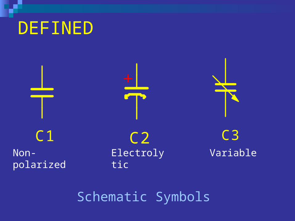
C1 C2 C350%
Schematic Symbols
Non-polarized Electrolytic Variable
CAPACITOR CODE
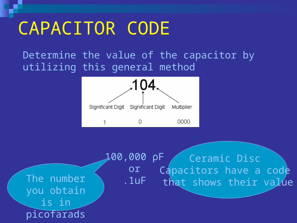
Ceramic Disc Capacitors have a code
that shows their value
100,000 ρFor
.1uFThe number you obtain is in picofarads.
Determine the value of the capacitor by utilizing this general method
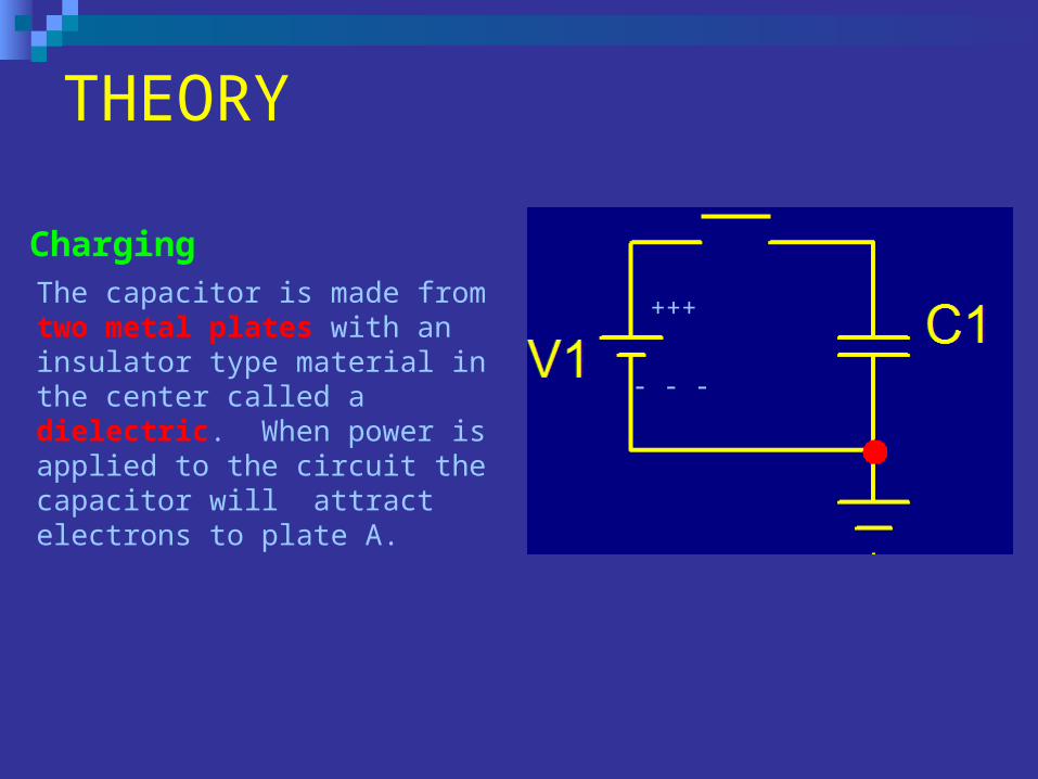
THEORY
+++
- - -
The capacitor is made from two metal plates with an insulator type material in the center called a dielectric. When power is applied to the circuit the capacitor will attract electrons to plate A.
Charging
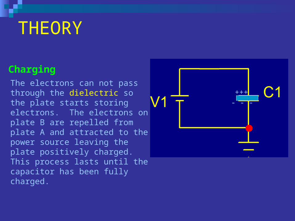
THEORY
+++
- - -
The electrons can not pass through the dielectric so the plate starts storing electrons. The electrons on plate B are repelled from plate A and attracted to the power source leaving the plate positively charged. This process lasts until the capacitor has been fully charged.
Charging
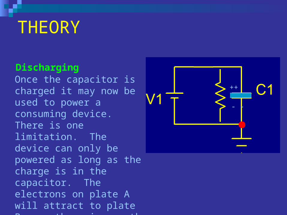
THEORY
Once the capacitor is charged it may now be used to power a consuming device. There is one limitation. The device can only be powered as long as the charge is in the capacitor. The electrons on plate A will attract to plate B once there is a path for them to flow. Once all the electrons have been neutralized, the capacitor has lost all of its charge.
Discharging
+++
- - -
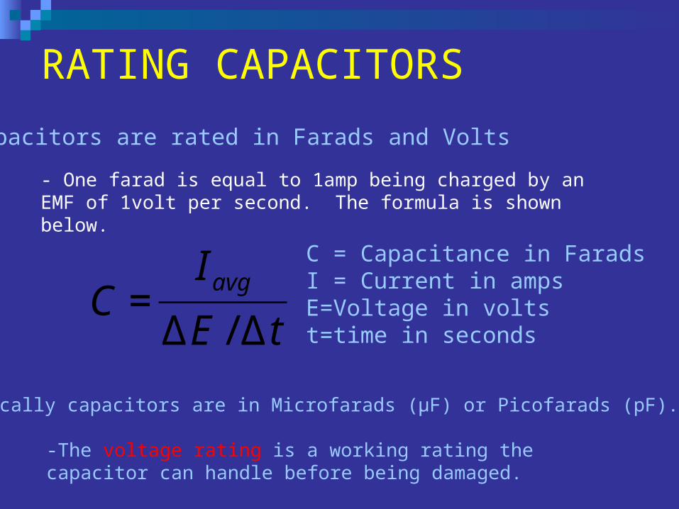
RATING CAPACITORS
Capacitors are rated in Farads and Volts
- One farad is equal to 1amp being charged by an EMF of 1volt per second. The formula is shown below.
tE
IC
avg
Δ/Δ=
C = Capacitance in FaradsI = Current in ampsE=Voltage in voltst=time in seconds
-Typically capacitors are in Microfarads (µF) or Picofarads (pF).
-The voltage rating is a working rating the capacitor can handle before being damaged.
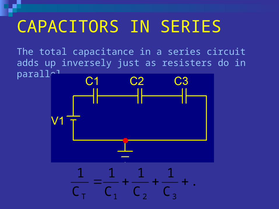
CAPACITORS IN SERIESThe total capacitance in a series circuit adds up inversely just as resisters do in parallel.
...C
1
C
1
C
1
C
1
321T
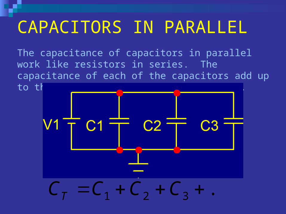
CAPACITORS IN PARALLELThe capacitance of capacitors in parallel work like resistors in series. The capacitance of each of the capacitors add up to the total capacitance of the circuit.
...321 CCCCT
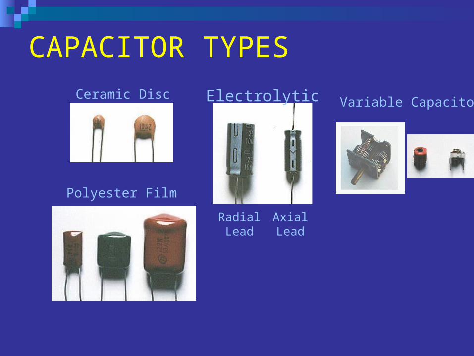
CAPACITOR TYPES
Ceramic Disc Electrolytic
RadialLead
AxialLead
Variable Capacitor
Polyester Film
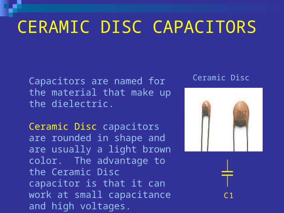
CERAMIC DISC CAPACITORS
Ceramic DiscCapacitors are named for the material that make up the dielectric.
Ceramic Disc capacitors are rounded in shape and are usually a light brown color. The advantage to the Ceramic Disc capacitor is that it can work at small capacitance and high voltages. C1
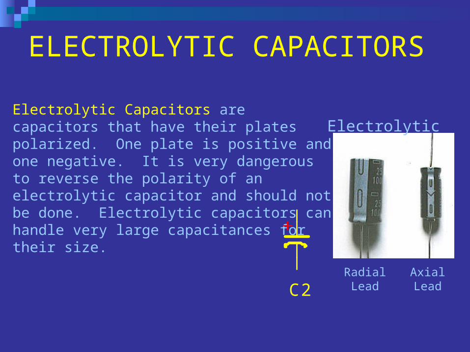
ELECTROLYTIC CAPACITORS
Electrolytic
RadialLead
AxialLead
Electrolytic Capacitors are capacitors that have their plates polarized. One plate is positive and one negative. It is very dangerous to reverse the polarity of an electrolytic capacitor and should not be done. Electrolytic capacitors can handle very large capacitances for their size.
C2
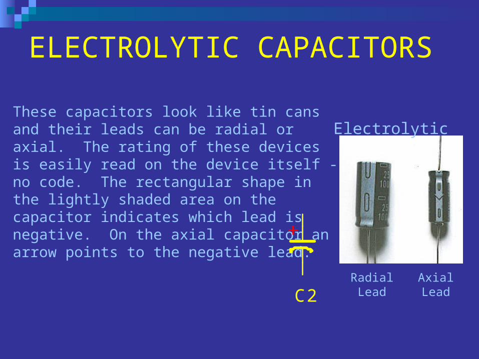
ELECTROLYTIC CAPACITORS
Electrolytic
RadialLead
AxialLead
These capacitors look like tin cans and their leads can be radial or axial. The rating of these devices is easily read on the device itself - no code. The rectangular shape in the lightly shaded area on the capacitor indicates which lead is negative. On the axial capacitor an arrow points to the negative lead.
C2
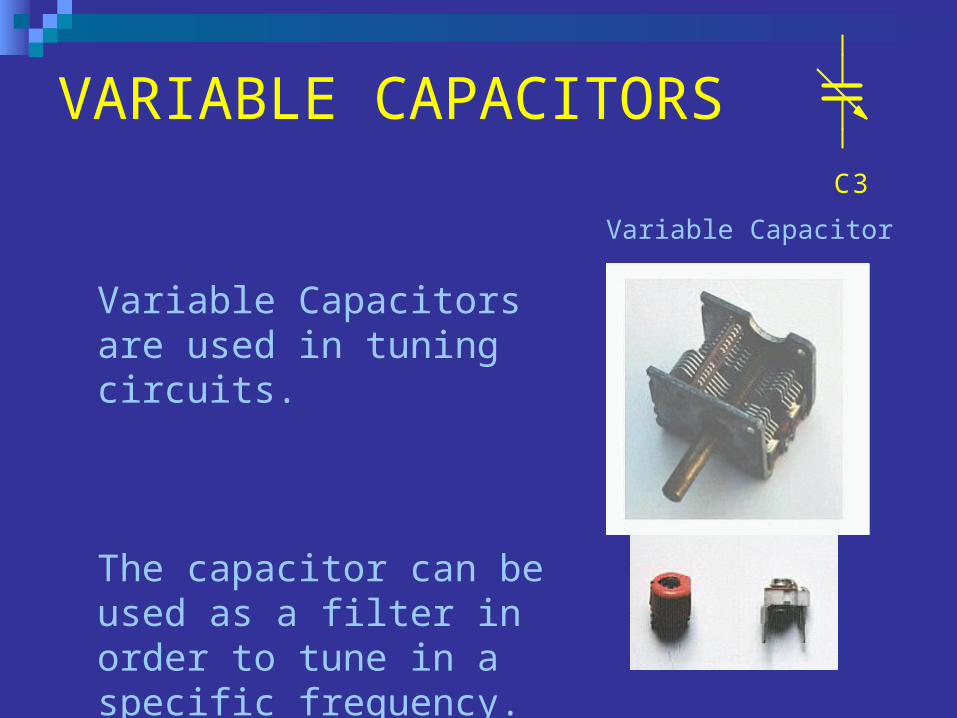
VARIABLE CAPACITORS
Variable Capacitor
Variable Capacitors are used in tuning circuits.
The capacitor can be used as a filter in order to tune in a specific frequency.
C350%
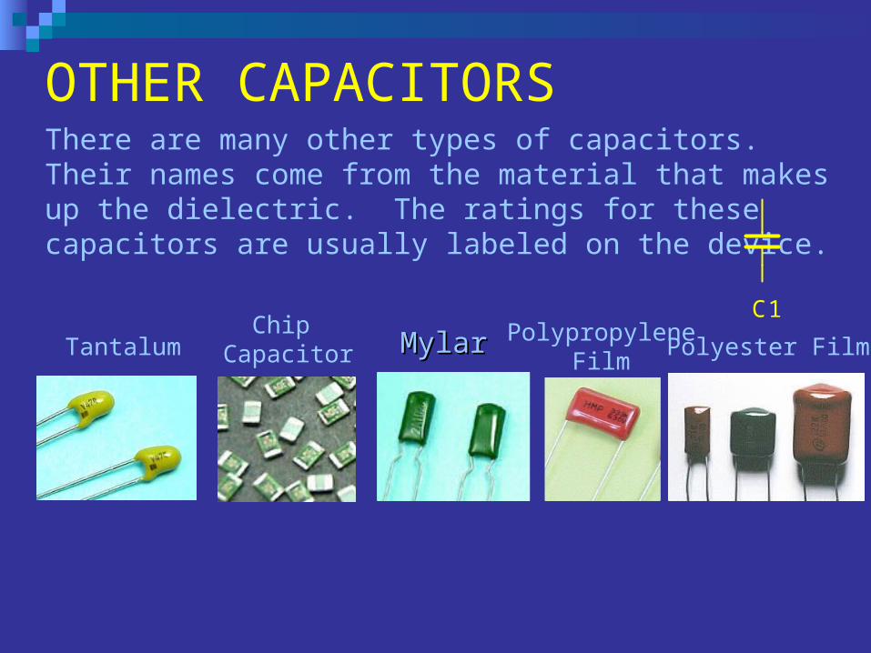
OTHER CAPACITORS
Polyester Film
There are many other types of capacitors. Their names come from the material that makes up the dielectric. The ratings for these capacitors are usually labeled on the device.
MylarMylar PolypropyleneFilm
Chip CapacitorTantalum
C1
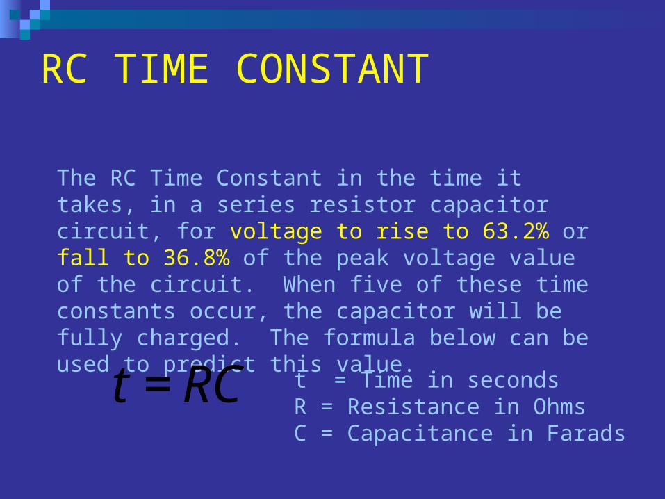
RC TIME CONSTANT
The RC Time Constant in the time it takes, in a series resistor capacitor circuit, for voltage to rise to 63.2% or fall to 36.8% of the peak voltage value of the circuit. When five of these time constants occur, the capacitor will be fully charged. The formula below can be used to predict this value.
RCt= t = Time in secondsR = Resistance in OhmsC = Capacitance in Farads
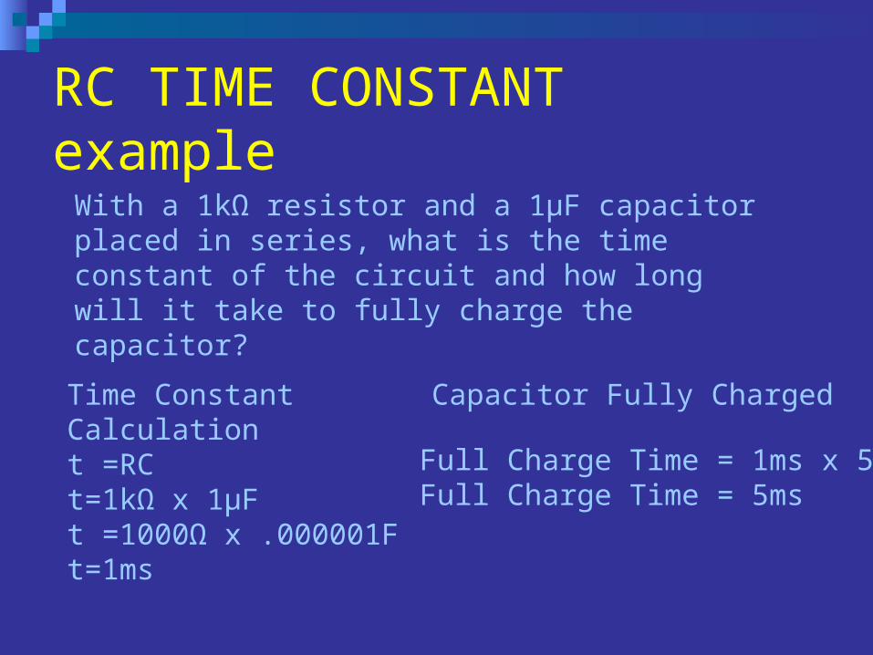
RC TIME CONSTANT example
With a 1kΩ resistor and a 1μF capacitor placed in series, what is the time constant of the circuit and how long will it take to fully charge the capacitor?
Full Charge Time = 1ms x 5Full Charge Time = 5ms
Capacitor Fully ChargedTime Constant Calculationt =RCt=1kΩ x 1μFt =1000Ω x .000001Ft=1ms
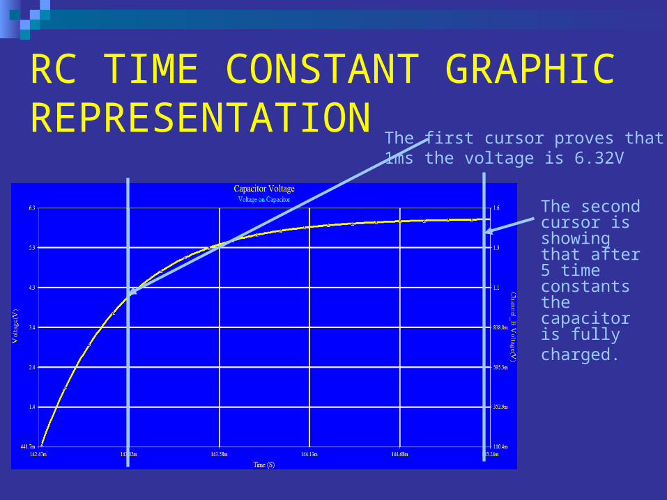
The first cursor proves that at 1ms the voltage is 6.32V
The second cursor is showing that after 5 time constants the capacitor is fully charged.
RC TIME CONSTANT GRAPHIC REPRESENTATION
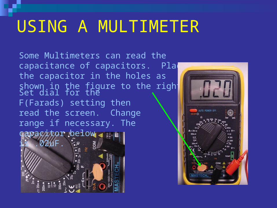
USING A MULTIMETER
Some Multimeters can read the capacitance of capacitors. Place the capacitor in the holes as shown in the figure to the right.
Set dial for the F(Farads) setting then read the screen. Change range if necessary. The capacitor below is .02uF.

End of Presentation


