
Sk national accelerator laboratory TJX~230 0323
CAPACITOR BANKS FOR BOOSTER RESONANT POWER SUPPLY
Jan Ryk
April 14, 1970
Preliminary studies regarding the capacitor banks for
the Booster Resonant Power Supply were started in 1968, The
goals set for the capacitors were the following.
1.
2.
3.
Low losses
Low stray capacitance to ground
Low variation of capacitance as a function of temperature
4.
5.
6,
7.
High degree of reliability
Easy replacement of faulted units
Possibility of mounting the capacitors in the magnet support girder
Low cost
The following information was obtained from different
capacitor manufacturers,
1. McGraw Edison Company (Line material industries)
a. The typical variation of capacitance as a function
of temperature between 20' and 50' C is 23i%, see
Figure 1,
TM-230 -2- 0323
b,
C,
Capacitor cans will usually not rupture if the
energy dumped into a faulted can does not exceed
5 kJ,
The typical capacitance from the terminals of a
capacitor to the can is 2000 pica farads. This
stray capacitance is constant to within 10% for
a given design,
2. Sangamo Electric
a,
b.
c.
d.
Typical variation of capacitance as a function
of temperature over the temperature range of
20' to 50' C is 2*%, see Figure 2.
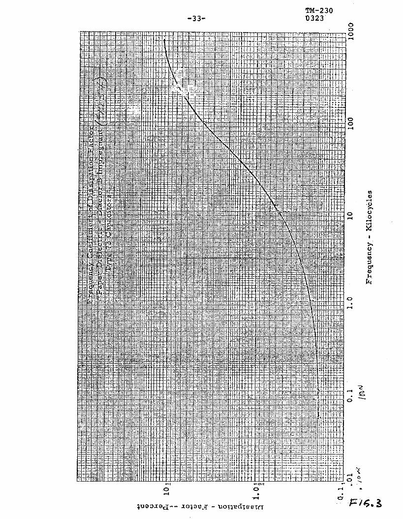
Dissipation factor expected for 15 Hz operation
is .6%1 see Figure 3.
Sangamo suggests to restrict the energy in a
capacitor bank to 15 kJ based on consideration
of rupture strength of standard fuses and capac-
itor cans.
Oil impregnated multilayer kraft paper is
usually used for dielectric. The winding of
individual capacitor packs is done in a temper-
ature, humidity, and dust controlled environment,

-3- TM-230 0323
3. Maxwell Laboratories
a, Typical dissipation factor expected at 15 Hz
operation is .25%, see Figure 4.
b, Typical dissipation factor dependence on temper-
ature is shown in Figure 5.
C, Typical impregnants used are:
. Aroclor, k = 6
II Silicone oil, k = 4, AC/AT < - 1% over 200 - 50' C, practically doubles the cost of the capacitors
. Silicat ester, k = 4, similar to silicone oil, both silicone oil and silicat ester requires 50% more volume for the same capacitance, due to the low k.
. Mylar, AC = +20% over 20° to 50° C, cost :: 2 times that of aroclor capacitors; losses; 2 times those for aroclor capacitors.
d. Water-cooled capacitors: volume 20% higher than
air-cooled capacitor due to cooling coil, cost
is 35% higher, cooling efficiency 30 to 40%.
e, Paper-film capacitors, using kraft paper and
polyprolene film. Losses about 25% of those of
paper capacitors, cost is twice as high, volume
about 30% larger,

TM-230 -4- 0323
f, Film capacitors: losses about 10% lower than
for the paper dielectric, volume about 6 times
larger, cost about 4 times higher,
Prototype Work
Based on the information received from the different
manufacturers and guided by the goals set for the capacitor
bank,. we came to the following requirements for the Booster
capacitor banks.
1.
2,
3.
The dissipation factor at the expected operating
temperature of 50 o C should not exceed .3%.
In order to further limit the losses, no internal
discharge resistors should be used.
The stray capacitance to ground should be minimized
by mounting the capacitor units in an insulated
structure, using single bushing capacitors, The
total capacitance appears now between the single
bushing and the can. With the can connected to the
structure, the stray capacitance to ground is now
determined by the insulation distance to ground
which can be large,
4. Use paper impregnated with aroclor as the dielectric.

TM-230 -5- 0323
This is the lowest cost and the most compact unit.
Aroclor is nonflammable and, therefore, good for
indoor use, A test report prepared by Underwriters
Laboratory regarding monsanto aroclor 1248 and 1242
is attached,
5. Can rupture is unlikely to occur since the maximum
stored energy in a Booster capacitor bank is 6 kJ.
In spite of this, the individual capacitor cans will
be fused to definitely prevent can rupture. Fuses
will be indicating type, Prevention of can rupture
will prevent burning of the paper dielectric which
can cause toxic fumes, as indicated in the report
mentioned under Item 4. Capacitor can rupture curves
and fuse clearing curves are attached (see Figures
6 & 7).
6. The capacitors will be assembled in modular structures
designed to fit in the magnet support structure.
Individual capacitor mounting and capacitor module
mounting will be such that individual units or modules
may be removed easily and fuse replacement can be
achieved easily.
7. Air-cooled capacitors will be used, because of the
following advantages over water-cooled units.

-6- TM-230 0323
a, Smaller volume
b, Lower cost
C. Elimination of extra cooling equipment
Furthermore, the maximum dissipation for air*cooled
capacitors is 1040 watts over a total area of 3700
square inches or .28 watts/sq in. The water-cooled
units could not be fitted in the available space in
the magnet support girder.
In order to evaluate manufacturing capabilities and
designs, we decided to obtain a prototype capacitor bank based
on our specifications from three different manufacturers. The
three different designs were evaluated by means of tests at
the manufacturers' plants and tests at NAL.
Final Capacitor Banks
The final capacitor banks decided upon have the following
design parameters.
Total capacitance per bank
Number of modules
Number of capacitor units per bank
Operating voltage
Operating frequency
8300 ~.IF + 301_1F
3
17 + 1 trimmer
815 V rms
15 Hz
TM-230 0323
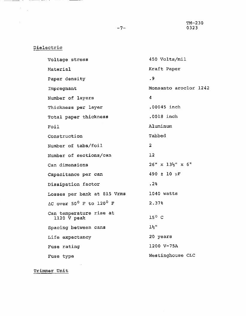
Dielectric -,
Voltage stress
Material
Paper density
Impregnant
Number of layers
Thickness per layer
Total paper thickness
Foil
Construction
Number of tabs/foil
Number of sections/can
Can dimensions
Capacitance per can
Dissipation factor
Losses per bank at 815 Vrms
AC over 50' F to 120' F
Can temperature 1120 V peak
Spacing between
Life expectancy
Fuse rating
Fuse type
Trimmer Unit
rise at
cans
450 Volts/mil
Kraft Paper
.9
Monsanto aroclor 1242
4
,00045 inch
.0018 inch
Aluminum
Tabbed
2
12
26" x 13%'" x 6'"
490 9 10 I-IF
.2%
1040 watts
2.37%
150 c
1% cs
20 years
1200 V-75A
Westinghouse CLC
TM-230 -8- 0323
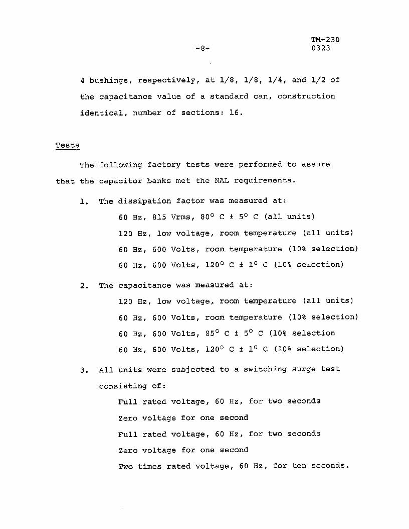
4 bushings, respectively, at l/8, l/8, l/4, and l/2 of
the capacitance value of a standard can, construction
identical, number of sections: 16.
Tests
The following factory tests were performed to assure
that the capacitor banks met the NAL requirements.
1. The dissipation factor was measured at:
60 Hz, 815 Vrms, 80° C i: 5O C (all units)
120 Hz, low voltage, room temperature (all units)
60 Hz, 600 Volts, room temperature (10% selection)
60 Hz, 600 Volts, 120° C + lo C (10% selection)
2. The capacitance was measured at:
120 Hz, low voltage, room temperature (all units)
60 Hz, 600 Volts, room temperature (10% selection)
60 Hz, 600 Volts, 85' C f 5' C (10% selection
60 Hz, 600 Volts, 120° C !: lo C (10% selection)
3. All units were subjected to a switching surge test
consisting of:
Full rated voltage, 60 Hz, for two seconds
Zero voltage for one second
Full rated voltage, 60 Hz, for two seconds
Zero voltage for one second
Two times rated voltage, 60 Hz, for ten seconds.

TM-230 -gn 0323
The capacitance and dissipation factor were measured
with a low voltage, 120 Hz bridge before and after
the switching surge test,
4. One unit, after it had passed all of the above tests,
was charged up by means of a dc power supply until
destruction, The unit failed at 7 kV, which corres-
ponds with a stored energy of l/2 x 490 x low6 x
(7000)2 = 12,000 Joules. The can bulged but did not
rupture.
5. A small quantity of the aroclor impregnated paper
dielectric in open air was burned by means of an
open flame, The paper burns readily, the aroclor
caused black smoke with irritating fumes. (Also
see the Underwriters' Laboratories test report on
aroclor.)
In addition to the factory tests, one complete capacitor
bank was operated at NAL under normal 10 GeV operating con-
ditions, The capacitor bank was mounted in a typical magnet
support structure, p laced in the Booster Prototype tunnel.
The can temperatures were recorded under these conditions.
The maximum can temperature rise was 15O C. The time necessary
to reach a stable temperature was 4% hours.

-lO- TM-230 0323
Conclusions
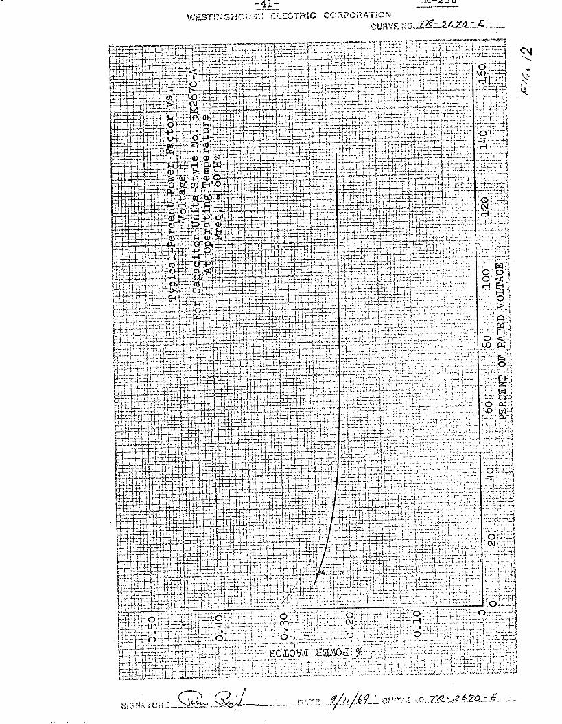
Typical performance curves of the capacitors are shown
in Figures 8 through 12. All units were fabricated from one
shipment of paper. The temperature and humidity during wind-
ing of the capacitors was controlled. The result was small
capacitance tolerance between individual cans.
The units that passed the stringent factory tests may
be considered very reliable. If we assume that one unit is
representative, we may conclude from factory test No. 4 that
can rupture under fault condition in the Booster system is
very unlikely since the maximum energy in a capacitor bank
at 10 GeV operation is 6 kJ and the test can did not rupture
under failure at 12 kJ.
Under these conditions we do not expect the capacitors
to form a fire hazard. The aroclor impregnant is non-flammable
at normal temperatures. As long as no can rupture occurs, the
paper will not burn.
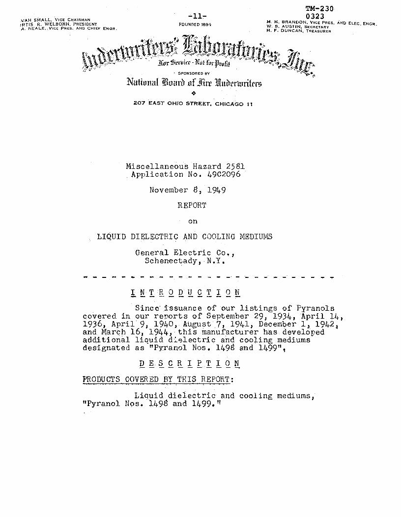
&JAI+ SMALL. VICE CHAIT~MAN iftrls R. WELBORN, P~~ES~DENT A. NEALE..VICE PRES. AND CHIEF ENOR.
-117 FOUNDED 1894
TM-230 0323
M. M. BRANDON. VICE PRES. i.ND ELEC. ENGR W. S. AUSTIN. SECRETARY H. F. DUNCAN. TREASURER
- SPONSORED BY
207 EAST OHIO STREET. CHICAGO 11
Miscellaneous Hazard 2581 Application No. 49C2096
November @ , 1949
REPORT
on
LIQUID DIELECTRIC AND CiK)LING XEDIUI\riS
General Electric Co,, Schenectady, N.Y.
INT Ra DU CT I ON c----------.--y Sincc'issuance of our listings of Pyranols
covered in our re?orts of September 29, 1934, 'April 14, 1936, April. 9, 1940E August 7, 1941, December 1, 1942, and March 16, 1944, this manufacturer has developed additional liquid dielectric and cooling mediums designated as "PyranolNos. 1498 and 1499",
DESCRIPTION ----------- PRODUCTS COVER$:D RY THIS REPORT: .,
Liquid dielectric and cooling mediums, llPyranol Nos, 1498 and 1499."

-12A TM-230 0323
MI42581 November 8, 191‘9
GENERAL CHARACTh% AND USE: c- The products which are the subject of this
report are chlorinated aromatic hydrocarbons. They are intended for use as dielectric and cooling mediums in electrical apparatus, They are not intended to renlace oil as a -dielectric and cooling medium unless eqkipment is designed for either oil or these products,
MARXIYG;
Vyranol Nos. lb% and 1499,"

TM-230 13- 0323
MH25dl November R, 1949
THE INVESTIGATION --- ---L--c-----~ The object of this investigation'was to
determine the fire and explosion hazard of the products,
In planning the'investigation consideration.was given to the-General Nature of the products, their Fire and Toxic Hazard, Corrosive Action! Stability, and Uniformity, The method of investigation of each of these phases is given below.
Information as to the general nature of the products Was obtained by means of Identification Tests,
In the study of fire and toxic hazards, the product was investigated as to flammability, explosive- ness of the vapors when mixed with air, products of decomoosition, arid decomnosition temnerature, The tests*included Flash Point Tests, Fire Tests, Ignition Temperature Tests, Tests for Zxplosiveness of Vap0r.s in Air, Explosive Range Tests, Decomposition Temperature Tests, and Analytical Tests of Decomposition Froducts,
Corrosion Tests on metals commonly used in electrical apparatus were conducted. In view of-the similarity of the products, corrosion tests were conducted on only one of the two products submitted?
Information bearing on the stability of the products was obtained frbm Decomposition Temperature Tests, Corrosion Tests, and consideration of the chemical propertiesof'the nroducts..
The process for manufacturing the products is subject to definite control, and a detailed investigation of factory process was not t;herelfore considered necessary.

TM-230 -14- ,0323
MI%!581 November 8, 1949
EXAMINATION AND TEST RECORD C_I-m.-.--l-- --- ---- -----a DESCRIFTION OF SAMPLES
The manufacturer furn,ished 5-gal samples of the products, Pyranol Nos. 1498 and 1499.
IDENTIFICATION TESTS: -CCL---.----S--.-.--- NETHODS
Snecific' Gra --The determined-
stiecific gravity was cnometer?
Test for Chlorine - A few drops of .the pro duct together w~?-%i& plze of metallic sodium are heated in jl test tube over a bunsen-burner, After the reaction is completed, the test tube is broken in water; the resulting solution is filtered; and nitric acid and silver. nitrate solution, are added,, The formation of a white precipitate indicates the presence.of chemically combined-chlorine. ,
Distillation Test r A 100-g .sample was distilled using the m~?%d~~~~~f the American Society for Testing ?4aterials,:
RESULTS
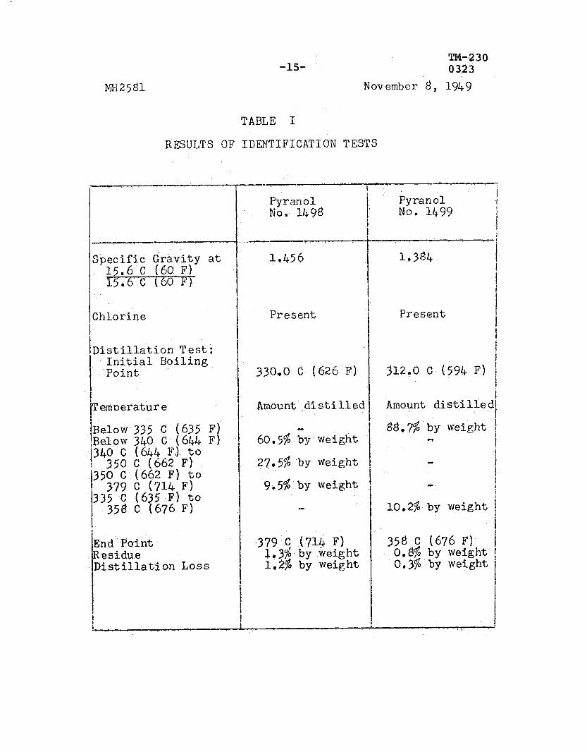
The results of the identification tests are recorded in Table I.
MH2y31
-15- TM-2 30 032.3
November d, 1949
TABLE; I
RESULTS OF IGENTIFICATION TESTS
Pyranol No. 1499
1,384
Chlorine Present I I f
I i
Distillation Test: I
/ Initial Boiling Point 330,O c (626 F) i %+O C (594 F) f
i I I i TemDerature Amount'.distilled Amount distilled
I
60.5% iy weight 88.7% by weight 1
- i
350 C (662 F) to 27.5% by weight i
379 C (714 F) 9,5% by weight 1 c i
335 C (635 F) to .k i
t 358 (3 (676 F) 10,2$ by weight 1 1 I
,379 C (71i F) ' 358 C (676 F) I
1.3% by weight 0,s by weight i
1;2$ by weight 0.35 by weight f
I I I

-16-
m12y31
TM-230 0323
November 8, 1947
FLASH POIET TESTS: .-de METHOD
The flash noint was determined with the Pensky- Martens closed tester using,the method (D93-46) of the American Society for Testing Materials.
RESULTS
,The results of the flash point tests are as 'allows:
1498 1499
FIRE TESTS:
Flash Point ---- (2)
196,l c'(385 F) 17697 C (350 F)
The fire tests were made with.the Cleveland open cupi using the method (D92-46) of the American Societv for Testing Materials,
RESULTS
The -samnle Nos, 14.98. and 1499 gave negative' (3)
results -in the fire tests, (4)
(2) In this connection, see Note 4,
(3) Intermittent flashes were obtained but the product ,did not continue to burn: The sample 'was heated to boiling point; the test was then discontinued.
(4) In view of the neFative results obtained,in the Fire Tests, it is clear that the flash point test cannot be depended'unon to give a true measure of the fire hazard of these.productst It was therefore necessary to conduct Tests for Explosiveness of Vapors in Air. See Page 9,

-17- TM-230 0323
November g, 1949
IGNITION TEMFZRATURE TESTS: -.--7 METHOD
The apparatus consists essentially of a combustion chamber surrounded by a solder bath, which is heated at a constant temperature during the test by a bunsen burner, The temperature of the solder bath is measured by means of a calibrated thermocouple provided with a quartz tube to grotect the hot junction.
The combustion chamber consists of a quartz flask of conical form with flat bottom 4-l/2 in, (11,4 cm) in height, 2-J/8 in, (6.0 cm j in diameter at bottom, and l-1/8 in. (2.8 cm) in diameter at top. It is of about 160-cc capacity*(rated capacity 125 cc) having a ratio of surface area to volume of about LL
Measured test samples in the liquid phase are introduced into the heated combustion chamber by mean5 of a.micro pipette,' Different amounts of the sample are admitted to the chamber in successive tests in order to.deternine the minimum temperature at which the vapor of the liquid in any proportion with air will ignite? The‘residual vapors or gases in the combustion chamber are comnletely displaced by a. stream of air in the interval between tests,

TM-230 0323 -18-
NH2581 November g, 1949
RESULTS
The results of the ignition temperature tests are tabulated below:
Sample .-N&* (5)
Ignition_~emn~rature .c
1498 672 C (1243 .F). 1499 652 C (1206 F)
.-7 c --.--,--.A . ..-.. -I*----c-----m-
The main value of the ignition test is to determipe the minimum temperature required to produce .ignition under the most favorable conditions in the absence of a flame or spark including ratio of vapor to air and ratio of heated.surface to volume of vapor-air mixture. Under less favorable conditions as when the liquid isapplied to a hot plate a higher temperature for ignition is required? .A limitation of the ignition test in a small v.essel is that it does not show whether flame propagation 'for any material. distance till occur, After determining the 'ignition temperature therefore it is necessary to.obtain additional data having a bearing on flame propagation. These data are given by Tests for Explosiveness of Vapors in Air,

-19-
MHiStll
TM-230 0323
November 8, 1949
TESTS FOR EXPLOSIVENESS OF VAPORS IN AIR: -,w--- METHOD
The apparatus consists of a cylindrical-steel vessel 6 in. in diameter (internal) and 26 in. long0 It is provided'with a small mica window and,an outlet to the atmosphere, The apparatus is heated externally by gas burners, Openings are provided half way between the ends ofthe vessel to admit electrode terminals con- nected to an induction coil, The electrode terminals are spaced to give a spark gap of l/l+in.
An iron-constantan thermocouple connected to a notentiometer is used for rough measurements of the temnerature of the vapor inside of the vessel.
Samnles.ranginE in volume from 20 to- 80 cc were introduced into the cylinder which had previously been heated to a predetermined temperature. The ,out- 'let of the cvlinder was closed with a loose asbestos PlW 7 Spark&Were passed,bettveen the electrode ter- minals at .i.nte'rvals of one-half minute,
Residual gases and vapors were displaced from the cylinder by a stream-of air in the interval between tests?
3.ESULTS
Sample No, 1498 - No propagati --c--- occurred at temperatures up to 14.8 C ( propagation with weak pressure effects push asbestos plug from outlet of cyli at 150 C (302 F). Moderate nre,ssure'S plug-thrown about 3 or 4 ft horizontal of.cyJinder) wer.e obtained at temperat above 150 C (302 F).
on of flame 29Ei.4.F). Flame
(sufficient to .nder) occurred effects (asbesto ly from outlet ur es smewhat
S
Samole No. 1499 - No propag,stion of flame occurred at temperatusesyp to.141 C (285.8 F). Flame propagation with weak pressure effects (sufficient to.push asbestos plug from the outlet of cylinder) occurred at 144 C (291,2 F) Moderate pressure effects (asbestos plug thrown about 3 or 4 ft horizontally from outlet of cylinder) were obtained 3-t temperatures someWhat above 144 C (291.2 J+

-2O- TM-230 0323
MH2@1
EXPLOSIVE RANGE TESTS: _I-
November 6, 1949
The apparatus consists essentially of a plass . . chamber equipped with a spark gap and a stirrer. The chamber is cylindrical with the lower end hemispherical and is approximately 3 in, in .diameter by'8 in? in height; it has a net volume of 863 cc, The' apparatus is provided with a glass lid supporting the stirrer and the leads to the spark gap near the bottom of the chamber. An opening in the -lid is provided for introduction of the sample. The-glass' chamber is immersed,in a,molten solder bath to a depth of 6 in.
In, conducting tests the solder bath was main-r tained at a constant temperature of 400 C (752 F), a measured quantity of the liquid to be tested was placed in the apparatus, and the vapors stirred. Sparks were then.passed at the spark gap while observa? tions were made for flame travel and pressure-effects? Following the testy -the vapors were displaced by a slow stream of compressed air in preparation for the next test,
RESULTS
The results of the explosive range tests of .Samnles Nos,&.yE! and 1499 in air at 400 C (752 F)
are'shown in Table II.
METHOD
The apparatus described in connection with Ignition Temperature T.ests was used in these testso, The vapors evolved on introducing samples into the heated chamber were tested with moist blue litmus paper., a change in the color of the paper.from blue to red indicating decomposition .of the product, The minimum temperature at which litmus paper showed an appreciable change in color within a short time (3 min) was considered to be the decomposition temperature,
RESULTS
The results of the decomposition temperature tests are recorded in the following table. -
Sample Nor, Deconpositi..n Temperature --- 305 c I581 F) 309 c (588 F)

-21- TM-330 November 6, 194.932:
__c__--q - --.. i
--e _ _ ._._ - .-..-- --_ I C-.
In 4’
cb A
_,-__- ___.- 4- -I.------ . .--_ - -_

TM-230 -22- 0323
November 8, 1949
@JALVTICAL TESTS OF DECOMPOSITION PROXJCTS:
METHOD
The cylinder previously described under Tests for Explosiveness of Vapors in Air was also used for exposing vapor-air mixtures to hot iron surfaces. Connections for withdrawing samples of the decomposition products for analysis were inserted in the outlet pipe,, The cylinder was externally heated to a tem- perature of 600 C (1112 F) by gas burners?
Samples of,the product in the liquid phase were introduced into the heated cylinder at a uniform rate. Samples of the decomposition products were withdrawn from the .outl.et pi,pe and hydrochloric acid, free chlorine, phosgene, carbog dioxide, oxygen, carbon monoxide I gases absorbed by fuming sulphuric acid and methane and other paraffin hydrocarbon gases, were determined using the following methods,'
Tests for free chlorine were made by liberation of iodine from aqueous potassium iodide solution and subsequent titration with sodium thiosulphate solution using starch solution as an indicator, A measured sample was drawn by a calibrated aspirator bottle through a train consisting of two spiral form bubbling toweri: containing pottassium iodide solution,
Phosgene was determined by absorption in aqueous aniline solution. Phosgene reacts quantita- tively with aniline to form diphenylurea, one molecule of phosgene'being equivalent to one molecule of diphenylurea,
A measured sample was drawn through a train of three bubbling towers containing freshly prepared aqueous aniline solution saturated with diphenylurea? Free chlorine interferes with the determination and was removed by granulated antimony contained in a tube through which the sample passed before it entered the bubbling towers, 'The precipitate of diphenylurea was separated from the" aniline solution by filtration, washed with cold water, dissolved in ethyl alcohol, recrystallized, dried, and weighed? I'

-23- TM-230 0323
lW2581 November 8, 1949
Samrsles of the 'decomposition products were also collected in evacuated glass sampling tubes, In these samnlcs hydrochloric acid was determined by solution in water and titration with standard alkali solution; carbon dioxide, carbo'n monoxide, oxygen, gases absorbed by fuming sulphuric acid, hydrogen, and paraffin hydrocarbon gases,, were determined with the Rurrell form of @as analysis apparatus after treating the'sample with silver nitrate solution to remove hydrochlorfc acid.
RSSULTS
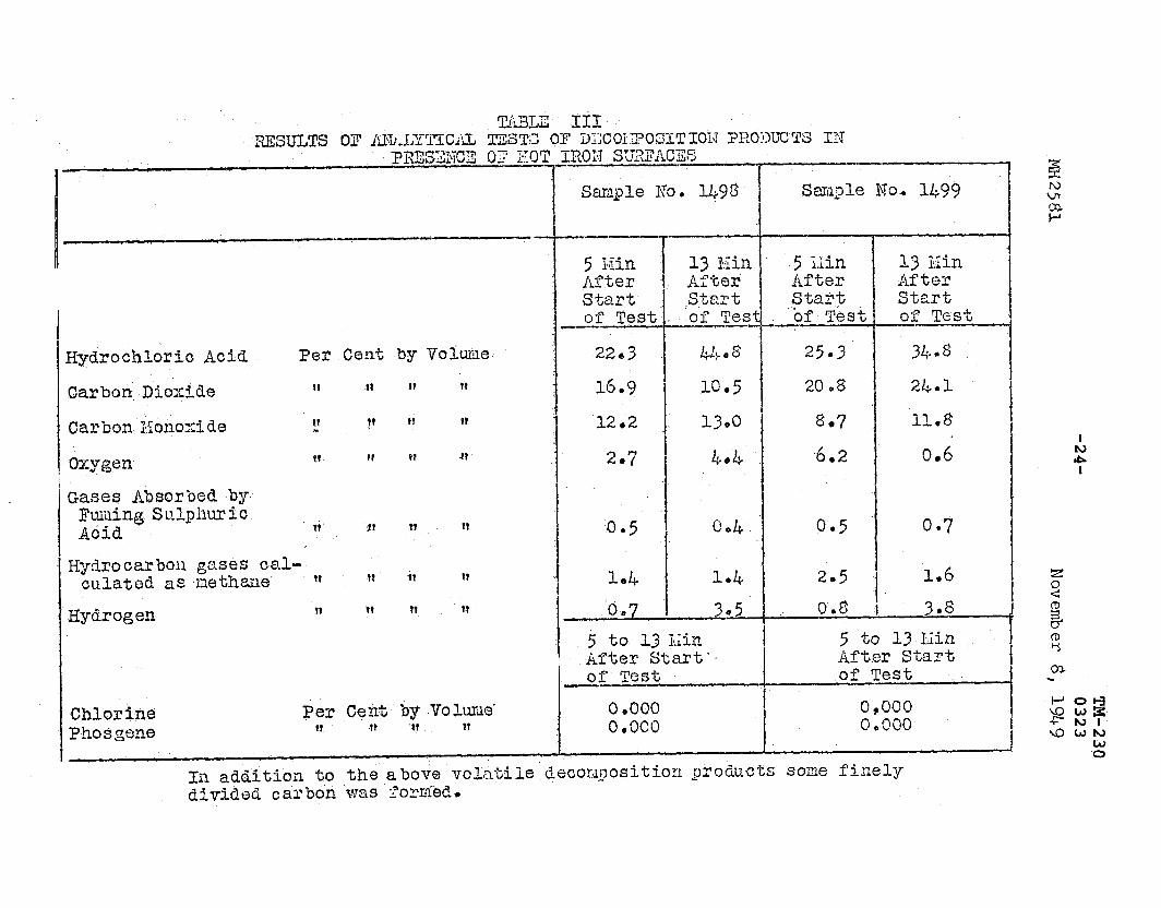
The ,l;esults of analytical tests of the de- composition croducts in the presence of 'hot iron. surfaces are.shown in Table III,
CORROSIoN TESTS* --• METHOD
The metals used in the corrosion,tests were, copper, yellow brass, iron;tin-lead.solder, and .' copper.and iron c-oupledt Test specimens, 3/4 in, wide and 6 in, long were cut.from sheets of the metals? The‘snecimens were buffed,measured, cleansed With soap and water, washed with ethyl alcohol and' ethyl ether, dried, and weighed.
Each specimen .W~S immersed for half its length in a sample of the product con%aine-d in a glass tube provided with a cork sto'L)perP The tubeswere he&ted to'a temperature oI f 90 C in an electrically-heated oven controlled by a thermostat,‘
The samples were-examined visually at weekly intervals during the test for evidences of corrosion, At the conclusion’of the test, the spec’imens were cleansed, dried, weighed and the change .'in tieight per souare centimeter of surface ar.ea calculated,
RESULTS
When heated in,glaSs tubes contaiiing Sample No, 1498 at 90 C fooP 1465 hours;the sr>ecimen.s showed little visible evidence of corrosion exe&t for a slight discoloration of the surfaces above the liquid, T‘h,e change in Weight of the specimens was very small (less than I,0 mg per sq cm),
5 ISin 13 Ein After After start start bf Test of Test
Hydrochloric Acid Per Cent by Vohile. 22s3 44.2 25.3 I 31j.8
Carbon,Dcoxide II -91 IF -1t 16.9 10.5 20.8 2b.l L
Carbon Xonoxide ?? ., ?’ fl PI 12.2 1300 se7 11,8
Oxygen tt It tt tt 2.7 4.16 .6.2 0.d
Gases m0rbea by Fuiiiing Sulphur ic i Acid 11. 3 n tt 1 '0.5 c;*4 0.5 0.7
jTQJdrocarboll gases Cal- culated as,nethme tt t? il I?
.I 1*4 1.4 205 1.6
Hydrogen ?? tf T? ‘?? I .'0,7 'I 305 1 ,' 0.8 I 3.8 1 1
1 5 to 13 Kin 1 5 to 13 Ui.n After Start’. After Start of Test of Test -
-Chlorine Per Cent by -Volumes 0 .ooo 0,000 Phosgene I? -1t ‘1? 9? o.oco 0,000
I In addition -to the above volatile’decoIx?osition products Some finely aivj.a& carbon was Zortied.

-25- TM-230 0323
MH2581 November 8, I.949
RECORD IN SERVICE c----I-- y--..---- The type of material represented by Pyranols
Nos. 1498 and 1.499 has been in commercial service in increasing amounts during the past several years* The value of these liquids as dielectric and cooling mediums has been demonstrated.
TFE.SUBHITTOR -4, ----r--w- The manufacturer, the.General Electric Company,
Schenectady, New York, is excerienced ,in th'e manufacture of electrical apparatus and related products, many of their products being listed by Underwriters1 Laboratories, Inch
'fhe products will be placed under Reexamination $ervicki
-26- TM-230 0323
Ml42531 November 8, 1949
These products are chlorinated aromatic hydra? carbons.
The results of the Identification Tests conducted indicate that the products are essentially hydrocarbons containing combined chlorine,
FIRE AND TOXIC HAZARD: -v--- These products are nonflammable at ordinary tempera-
twe 3 . They- are capable oL P forming moderately combustible . .._. and explosive mixtures with air under laboratory test-
conditions at higher temperatures, beginning: at a tempera-
ture level of ,150 C (302 F), in case- of‘Pyrano1 fqo; 1498
dnd 1LL. C (291,2 F) in the case of Fyranol No+ 1499, but
under practical conditions formation of combustible or
explosive mixtures is reparded as extremely unlikely, The
fire hazard is very small,
It will be noted'that the flash points of the products are comparatively high, and that a so-called "fire point" was not obtained. While intermittent flashes occurred in this test, the products did not continue to burn. The flash point and so-called "fire point‘" tests, partic'ularly the latter, in the case of chlorinated hydrocarbons are of limited value as a measure of fire hazard but are-useful for purpases of identification. The practical significance of the above tests in the case of the products in question is that their fire hazard is of a low order.
As shown by the results'of Tests for Explosiveness of Vapors in Air, vagors of Pyranol No, 1498 failed to -ignite or explode in tests at 148 C (298,4 F) but weak combustion occurred in tests at lT.Q.C_._(jOZ F)+- Vapors of Pyranol

TM-230 -27- 0323
MH256'1 November 8, 1949
No. 1499 failed to ignite or explode in tests at 141 C (285,8 F) but weak combustion occurred in tests at 14-l+ C (291,2 F), Moderate explosions were obtained in tests at temperatures somewhat above these minimum values. At a temberature of 400 C (752 F) the lower limits of flammability (upward propagation) of the vapors of Pyranol Nos..~---lr4gb-and.1499 v&r%' found to be 1-1 per.cent and 1.3 per cent by volume in air respectively and the corresponding upper limits of flammability (upward propagation) were found to be joy per cent by volume. It will be noted that these are comparatively narrow exnlosive ranges
The minimum ignition temperatures of the productS Were found t.c, be 672 C(l243 F),-and 652 C (1206 F) for Pyranol Nos. 1498 and 1499 'respectively as recorded in the results of Ignition Temperature Te.sts,
The pases produced by burning or decomposition of the products by heat are nonflammable or nonexplosive alone or .mixed with air, In previous tests of similar products the gases formed by burning or decornpqsition were' similar irrespective of whe ther formed by hot surfaces or electric arcs.
The gases or fumes produced by decomposition of the products include hydrochloric acid and carbon monoxidet- This will ordinarily constitute a toxic .hazard only where the conditions are such as to cause confinement of the fumes as in a closed room in which combustion or decomposition of the products is maintained by fire;highly heated surfaces, or electric arcs.
It is to.be noted in this connection that oils in common use at present as the dielectric medium for electrical ap.paratus are readily combustible and when burning under conditions of restricted air supply form. carbon'monoxide in dangerous concentrations.
The resulting concentration of hydrochloric acid in air when failure of a transformer or other electrical apparatus containing these products occurs will depend largely upon the conditions. It will constitute a toxic hazard only where the conditions are such as to cause a high concentration of the fumes as in a closed room, In ordinary use, the small quantities of gases evolved will be vented to some safe location.

TM-230 -28- 0323
MH2581 November 8, 19&9
The exceedingly unpleasant and irritating fumes from the decomDosition of these products even in concentrations of a very low order act not only to give warning of their presence but to prevent dangerous exposure of persons. While carbon monoxide is odorless and toxic its formation from these products .is,alyays accombanied by the simultaneous Xforma,tion of hydro- chloric acid gas which gives adequate warning of ,its presence as brought out above..
It will-be noted that combustion and decomposition of the products was maintained by heated surfaces (600 C, 1112 F) in carrying out the analytical tests,of the decomposition products, As shown by the results of the Decomnosition Temperature Tests,.the products were not appreciabiy'decomposed at temperatures below 305 C (581 F),
The products do not corrode the metals commonly
used in electrical apparatus,
No corrosion occurred in the tests conducted on representative metals and+alloys as recorded under Corrosion Tests..
It will be noted from the results of Analytical Tests of Decomposition Products that appreciable amounts of hydrogen chloride are formed on combustion.or de- composit?.on of the products in the presenc'e of hot metal surfaces,
STABILITY_:
The products are reasonably stable and'in use
are unlikely-to undergo deoompositlon resulting in an
increase in fire hazard,
In the Decomposition Temperature,Tests. the products did not undergo appreciable decomposition at t,emperatures below 305 C (561 F). Considerations of the chemical structure and,properties of the.products also indicate that they are reasonably stable,

MHZ581
TM-230 -290 0323
November 8, 1949
UNIFO?.MITY: W.--P- Considering the general process of manufacture,
it appears to be practicable to maintain a high standard
of uniformity on a commercial scale,

-3o- TM-230 0323
R EC OMMEN D AT I ON --------1-1---
TO THE ELECTRICAL AND FIRE COUNCILS OF UNDERV\RITERSk LABORATORIES, INC.
We recommend promulgation of the following notice to subscribers and the action indicated thereby:
Guide No, 80 IO, November 8, 1949. File &%2581,
General Electric Copt Mfr.,, 1 River Rd., Schenectady, N,Y,
Dielectric Mediums.
Synthetic liquids intended for use as dielectric and cooling mediums in electrical apparatus, particularly transformers, cables, and capacitors.
Nonflammable and nonexplosive at ordinary temperatures. I4arking: t'Pyranol Nos. 1498 and 1499,"
Listed by Report - Further infornlation is contained in a reoort dated November 8, 1949, copy of which may be obtained either from the manufacturer or from Underwriters' Laboratories, Inc.' (These products are not intended to replace oil as a dielectric and cooling medium unless equipment is designed for either-oil or t,hese products,)
See description of Reexamination Service on guide card,
Tests bv: Report by: C, C, Ciogston J? F. McArdle R, L, Donohue
c, CJ CLOGSTOP Physical Chemi&
Chemical Engineer
The foregoing Recommendation has been acceptea l.w!7-49 UNDERWRITERS' LARORATORIE-S, INC?
w. 3; Austin Secretary


-j... j.--;--;-+ j i ! : : i 1 j / 1 : I > f
-'~-,--.i ---..,-.- ?--‘.~--i-T-r--;--i--'--^l.--r-
; 1 i -....-.A-- i_ 1 1
-.i--,-i. 1 i f
.- __A.._ ‘L-!- : I / I
TM-230 -33- 0323
0

-34 TM-230 0323

TM-230 -35- 0323
.a. ’ !,“!!!’ I I I II
1 ZObJE ‘2 I 1 III .2-WITABLE FOd LOCATlONS--
tfdk+ICH HAVE. BEEN CHOSEN AFTER CAREFUL CONSDERATI
SP
TO POSSIBLE CONSEQUENCE -ASSOCIATED WITH VIOLENT& . ;, Z RUPTURE OF CA@= - I
.06 I I I --
*For times shorter than 1 cycle use asymmetrical rms amperes.
Fig. 6-3
CURRENT-VERSUS-TIME FOR A CAPACITOR UNIT TO RUPTURE DUE TO GAS PRESSURE CAUSED BY INTERNAL ARCING FOR 100 KVAR UNITS

-36- TM-230 0323
I--
IO0 So 00 10
00
SO
40 .-I.-:- .+-;
: / ’ / 1 !- +.LI 1 r-1
j ~$--+- ’ I i I i I i I I I L I -- ifti
I.4 “.yI CURRENT IN AMPERES
Total Clearing TIME.CURRENT CHARACTERISTIC CURVES
1 ,,..Qp.fz.CL$ Capacitor Fuses
I &A Dated
1 Vohs a-c at p-f., Starting at 2SC with no inilial load


_._ ..-._*


-4o- TM-230
d


