Download - Catálogo Industrias Arruti SA


COMPOSICIONES TIPICAS DE CADENASTYPICAL INSULATOR STRING DRAWINGSSCHEMAS TYPYQUES DE MONTAGE DES CHAINES
ENGANCHES A TORRETOWER ATTACHMENTSACCROCHAGE AU PYLÔNE
HERRAJES DE CADENASTRING HARDWAREMATERIEL DE CHAINE
YUGOSYUGOSPALONNIERS
PROTECCIONESSTRING PROTECTIONSPROTECTIONS DU CHAINE
GRAPAS DE SUSPENSION Y DE AMARRE PARA CONDUCTORES DE ALUMINIOCONTRAPESOS Y VARILLAS DE PROTECCIÓNSUSPENSION AND STRAIN CLAMPS FOR ALUMINIUM CONDUCTORSCOUNTERWEIGHTS AND ARMOUR RODSPINCES DE SUSPENSION ET D'ANCRAGE POUR CONDUCTEURS D'ALUMINIUMCONTREPOIDS ET ARMOR RODS
12345
INDICEINDEX
INDEX
0
6789
1011
ACCESORIOS PARA CABLE DE TIERRAACCESSORIES FOR EARTHWIREACCESSOIRES POUR CABLE DE GARDE
CONEXIONESCONNECTORSRACCORDS
COMPRESIÓNCOMPRESSIONCOMPRESSION
ACCESORIOS PARA CONDUCTORESCONDUCTOR ACCESSORIESPIECES DE CABLE
ACCESORIOS PARA CABLES DE FIBRA OPTICAFIBRE OPTIC CABLE ACCESSORIESPIECES DE CABLE A FIBRES OPTIQUES
POLEAS DE TENDIDO Y RODILLOSSTRINGING BLOCKS AND UNDERGROUND ROLLERSPOULIES DE POSE DE CABLES ET ROLEAUX SOUTERRAINS

TYPICAL INSULATOR STRING DRAWINGS
COMPOSICIONES TIPICAS DE CADENAS
SCHEMAS TYPYQUES DE MONTAGE DES CHAINES

CADENA DE SUSPENSION SENCILLASINGLE SUSPENSION STRING / CHAINES SIMPLE DE SUSPENSION
•0-1•
INDUSTRIAS ARRUTI, S.A. SPAIN • Internet: http://www.arruti.com

INDUSTRIAS ARRUTI, S.A. SPAIN • Internet: http://www.arruti.com
•0-2•
CADENA DE SUSPENSION SENCILLA PARA CONDUCTOR DOBLESINGLE SUSPENSION STRING FOR TWIN BUNDLECHAINE SIMPLE DE SUSPENSION POUR DOUBLE CONDUCTEUR
CADENA DE SUSPENSION DOBLE PARA CONDUCTOR SENCILLODOUBLE SUSPENSION STRING FOR SINGLE CONDUCTORCHAINE DOUBLE DE SUSPENSION POUR SIMPLE CONDUCTEUR

CADENA DE SUSPENSION DOBLE PARA CONDUCTOR DUPLEXDOUBLE SUSPENSION STRING FOR TWIN BUNDLECHAINE DOUBLE DE SUSPENSION POUR DOUBLE CONDUCTEUR
INDUSTRIAS ARRUTI, S.A. SPAIN • Internet: http://www.arruti.com
•0-3•

INDUSTRIAS ARRUTI, S.A. SPAIN • Internet: http://www.arruti.com
•0-4•
CADENA DE SUSPENSION DOBLE EN “V” PARA CONDUCTOR DUPLEX“V” DOUBLE SUSPENSION STRING FOR TWIN BUNDLECHAINE DOUBLE DE SUSPENSION EN “V” POUR DOUBLE CONDUCTEUR
CADENA DE SUSPENSION DOBLE EN “V” PARA CONDUCTOR TRIPLE“V” DOUBLE SUSPENSION STRING FOR TRIPLE BUNDLECHAINE DOUBLE DE SUSPENSION EN “V” POUR TRIPLE CONDUCTEUR

CADENAS DE AMARRE SENCILLOSINGLE TENSION STRINGS / CHAINES SIMPLES D'ANCRAGE
INDUSTRIAS ARRUTI, S.A. SPAIN • Internet: http://www.arruti.com
•0-5•

INDUSTRIAS ARRUTI, S.A. SPAIN • Internet: http://www.arruti.com
•0-6•
CADENAS DE AMARRE SENCILLA PARA CONDUCTOR DOBLESINGLE TENSION STRING FOR TWIN BUNDLE / CHAINE SIMPLE D'ANCRAGE POUR DOUBLE CONDUCTEUR
CADENAS DE AMARRE DOBLE PARA CONDUCTOR SENCILLODOUBLE TENSION STRING FOR SINGLE CONDUCTORCHAINE DOUBLE D'ANCRAGE POUR SIMPLE CONDUCTEUR

CADENA DE AMARRE DOBLE PARA CONDUCTOR DUPLEXDOUBLE TENSION STRING FOR TWIN BUNDLE / CHAINE DOUBLE D'ANCRAGE POUR DOUBLE CONDUCTEUR
INDUSTRIAS ARRUTI, S.A. SPAIN • Internet: http://www.arruti.com
•0-7•

CADENA DE SUSPENSION PARA CABLE DE TIERRAEARTHWIRE SUSPENSION STRING / CHAINE DE SUSPENSION POUR CABLE DE GARDE
INDUSTRIAS ARRUTI, S.A. SPAIN • Internet: http://www.arruti.com
•0-8•

CADENA DE AMARRE PARA CABLE DE TIERRAEARTHWIRE TENSION STRING / CHAINE D'ANCRAGE POUR CABLE DE GARDE
INDUSTRIAS ARRUTI, S.A. SPAIN • Internet: http://www.arruti.com
•0-9•

CADENAS DE AMARRE PARA CABLE DE TIERRAEARTHWIRE TENSION STRINGS / CHAINES D'ANCRAGE POUR CABLE DE GARDE
INDUSTRIAS ARRUTI, S.A. SPAIN • Internet: http://www.arruti.com
•0-10•

ENGANCHES A TORRE
ACCROCHAGE AU PYLÔNE
TOWER ATTACHMENTS

GRILLETES RECTOSSTRAIGHT SHACKLES / MANILLES DROITS
Utilización / Usage / UtilisationNormalmente se utilizan como primera pieza de enganche de la cadena a la torre.These parts are normally used as first element of the string for attachment to the tower.Ils sont utilisés d’habitude comme première pièce d’ancrage de la chaîne directement au pylône.
Materiales / Material / MatièreCuerpo: acero forjado galvanizado en caliente. Tornillos y bulones: acero galvanizado en caliente. Pasadores: aceroinoxidable o latón.Body: Forged steel hot dip galvanized. Bolt, nut and clevis pin: steel hot dip galvanized. Cotter pin: stainless steel orbrass.
Corps: acier forgé galvanisé à chaud. Boulon, écrou et axe: acier galvanisé à chaud. Goupille: acier inoxydable oulaiton.
INDUSTRIAS ARRUTI, S.A. SPAIN • Internet: http://www.arruti.com
•1-1•
ReferenciaCode
RéférenceFig
mmCarga de roturaUltimate strength
Charge de rupture(daN)
PesoWeightPoids(Kg)A C D E L
GN-11 1 20 12 16 12 60 10.000 0,350GN-11T 2 20 12 M-16 12 60 10.000 0,400GN-16 1 24 16 16 18 68 13.500 0,500GN-16T 2 24 16 M-16 18 68 13.500 0,550GN-16-L 1 22 16 16 18 90 13.500 0,550GN-16T-L 2 22 16 M-16 18 90 13.500 0,600GN-20 2 25 19 M-18 21 94 21.000 1,000GN-20/M-20 2 25 19 M-20 21 94 22.000 1,100GN-24 2 25 19 M-22 21 94 24.000 1,200GN-36 2 30 26 M-24 27 108 36.000 1,700GN-50 2 30 30 M-33 30 115 50.000 3,500
A
ØD
LE
C
A
LE
D
C
Fig. 1 Fig. 2

GRILLETES REVIRADOSTWISTED SHACKLES / MANILLES CHANTOURNES
Utilización / Usage / UtilisationNormalmente se utilizan como primera pieza de enganche de la cadena a la torre.These parts are normally used as first element of the string for attachment to the tower.Ils sont utilisés d’habitude comme première pièce d’ancrage de la chaîne directement au pylône.
Materiales / Material / MatièreCuerpo: acero forjado galvanizado en caliente. Tornillos y bulones: acero galvanizado en caliente. Pasadores: aceroinoxidable o latón.Body: Forged steel hot dip galvanized. Bolt, nut and clevis pin: steel hot dip galvanized. Cotter pin: stainless steel orbrass.
Corps: acier forgé galvanisé à chaud. Boulon, écrou et axe: acier galvanisé à chaud. Goupille: acier inoxydable oulaiton.
•1-2•
A
ØD
LC
A
D
LC
Fig. 1 Fig. 2
ReferenciaCode
RéférenceFig
mmCarga de roturaUltimate strength
Charge de rupture(daN)
PesoWeightPoids(Kg)A C D L
GR-16 1 24 16 16 90 12.500 0,650GR-16T 2 24 16 M-16 90 12.500 0,700
INDUSTRIAS ARRUTI, S.A. SPAIN • Internet: http://www.arruti.com

Utilización / Usage / UtilisationSe utilizan como primera pieza de enganche de la cadena a la torre.U- Bolts are used to attach the string to the tower.Il est employé comme première pièce d’ancrage au pylône
Materiales / Material / MatièreAcero galvanizado en caliente.Steel hot dip galvanized.Acier galvanisé à chaud.
Esta tabla contiene tipos de fabricación normal. Bajo pedido se podrá fabricar cualquier otra referencia.This table shows the most standard types; any other is available under request.Cette table contient les types de fabrication normale. On peut fabriquer d’autres références sur commande.
ESTRIBOSU-BOLTS / ETRIERS
TORNILLOS DE CANCAMOEYE BOLTS / OEILLETS BOULON
Utilización / Usage / UtilisationSe utilizan para fijar la cadena en postes de madera u hormigón.U- Bolts are used to attach the string to wood and concrete poles.Il est employé pour la fixation de la chaîne au pylône de bois ou béton
Bajo pedido se podrán suministrar estas referencias con otras longitudes.Eye bolts with different length are available under request.Sur commandé on peut fournir ces références avec la longer souhaité
ReferenciaCode
Référence
mmCarga de roturaUltimate strength
Charge de rupture(daN)
PesoWeightPoids(Kg)L R
TC-16-40 1 40 40 5.000 0,350TC-16-100 1 100 50 5.000 0,450TC-16-160 1 160 50 5.000 0,550TC-16-250 1 250 160 5.000 0,650TC-16-340 1 340 160 5.000 0,800TC-16-400 1 400 180 5.000 0,900C-15 2 ---- ---- 5.000 0,240
Fig.
Materiales / Material / MatièreAcero galvanizado en caliente.Steel hot dip galvanized.Acier galvanisé à chaud.
•1-3•
Ø35 Ø35Ø16
Ø63 31 L
R
M-16
35M-16Ø
35
Ø63
Fig. 1 Fig. 2
A
M
RL
ReferenciaCode
Référence
mmCarga de roturaUltimate strength
Charge de rupture(daN)
PesoWeightPoids(Kg)A ML
E-12x 40x 90 40 79 M-12 52 8.000 0,250E-14x70x120 70 107 M-14 70 8.000 0,400E-16x70x130 70 115 M-16 75 12.000 0,570E-18x70x130 70 114 M-18 80 16.000 0,730E-18x90x150 90 150 M-18 95 16.000 0,900
R
INDUSTRIAS ARRUTI, S.A. SPAIN • Internet: http://www.arruti.com
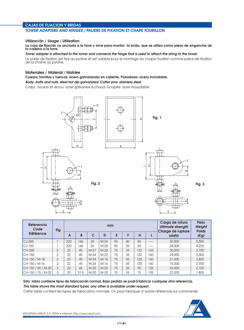
CAJAS DE FIJACION Y BRIDASTOWER ADAPTERS AND HINGES / PALIERS DE FIXATION ET CHAPE TOURILLON
Utilización / Usage / UtilisationLa caja de fijación va anclada a la torre y sirve para montar la brida, que se utiliza como pieza de enganche dela cadena a la torre.Tower adapter is attached to the tower and connects the hinge that is used to attach the string to the tower.Le palier de fixation est fixé au pylône et est valable pour le montage du chape tourillon comme pièce de fixationde la chaîne au pylône.
Materiales / Material / MatièreCuerpo, tornillos y tuercas: acero galvanizado en caliente. Pasadores: acero inoxidable.Body, bolts and nuts: steel hot dip galvanized. Cotter pins: stainless steel.Corps, boulon et écrou: acier galvanisé à chaud. Goupille: acier inoxydable.
•1-4•
FØC
E
D
H B
A Fig. 1
L H
B
F
C
D
E
A
F
B
HL
C
DA
E
Fig. 2 Fig. 3
INDUSTRIAS ARRUTI, S.A. SPAIN • Internet: http://www.arruti.com
ReferenciaCode
RéférenceFig
mmCarga de roturaUltimate strength
Charge de rupture(daN)
PesoWeightPoids(Kg)A B C D E F H L
CJ-300 1 220 146 30 M-24 90 40 50 ---- 30.000 5,500CJ-150 1 220 146 26 M-20 90 35 50 ---- 24.000 4,250CH-300 2 22 45 M-27 M-22 75 35 120 165 30.000 3,750CH-150 2 22 45 M-24 M-22 75 35 120 160 24.000 3,000CH-150 / M-18 2 22 45 M-24 M-18 75 35 120 160 21.000 2,800CH-150 / M-16 2 22 45 M-24 M-16 75 35 120 160 15.000 2,750CH-150 / 90 / M-20 3 22 45 M-20 M-20 75 35 90 125 22.000 2,100CH-150 / 75 / M-20 3 22 37,5 M-20 M-20 75 35 75 105 22.000 1,800
Esta tabla contiene tipos de fabricación normal. Bajo pedido se podrá fabricar cualquier otra referencia.This table shows the most standard types; any other is available under request.Cette table contient les types de fabrication normale. On peut fabriquer d’autres références sur commande.

HERRAJES DE CADENA
STRING HARDWARE
MATERIEL DE CHAINE

HORQUILLASCLEVIS EYES / CHAPES
Utilización / Usage / UtilisationSe utilizan normalmente para conectar los herrajes finales de la cadena de aisladores con las grapas de amarre ysuspensión.Clevis eyes are normally used to connect the end hardware of the insulator string to the tension and suspensionclamps.Les chapes sont utilisées d’habitude pour connecter les accessoires de la fin de la chaîne d’isolateurs avec les pincesd’ancrage et suspension.
Materiales / Material / MatièreCuerpo: acero forjado galvanizado en caliente. Tornillería: acero galvanizado en caliente. Pasadores: acero inoxidableo latón.Body: Forged steel hot dip galvanized. Bolts and nuts: steel hot dip galvanized. Cotter pin: stainless steel or brass.Corps: acier forgé galvanisé à chaud. Boulon et écrou: acier galvanisé à chaud. Goupille: acier inoxydable ou laiton.
Se añadirá la cota E al final de la referencia. Ejemplo: Si se necesita una cota “F” de 22 mm.:HP-16/22.Width E must be added to code as a suffix. For instance: HP-16/22 for F=22Ajouter la cote E sélectionnée à la fin de la référence. Par exemple: HP-16/22 pour F=22
•2-1•
INDUSTRIAS ARRUTI, S.A. SPAIN • Internet: http://www.arruti.com
LB
D
A
E
ØC
ReferenciaCode
Référence
mmCarga de roturaUltimate strength
Charge de rupture(daN)
PesoWeightPoids
(Kg max)A DC LB E max.
HP-16 / E 25 38 17,5 M-16 45 90 13.500 1,100HP-20 / E 25 38 20,5 M-18 45 90 18.000 1,150HP-20-21 / E 25 38 23,5 M-22 45 90 21.000 1,250
LB
D
A
ØC
E
ReferenciaCode
Référence
mmCarga de roturaUltimate strength
Charge de rupture(daN)
PesoWeightPoids
(Kg max)A DC LB E max.
HR-16 / E 25 34 17,5 M-16 45 80 13.500 1,000HR-20 / E 25 34 20,5 M-18 45 80 18.000 1,100HR-20-21 / E 26 34 23,5 M-22 45 80 21.000 1,200HR-24 / E 30 45 23,5 M-22 22 100 24.000 1,600HR-24-30 / E 30 45 26 M-24 22 100 30.000 1,700
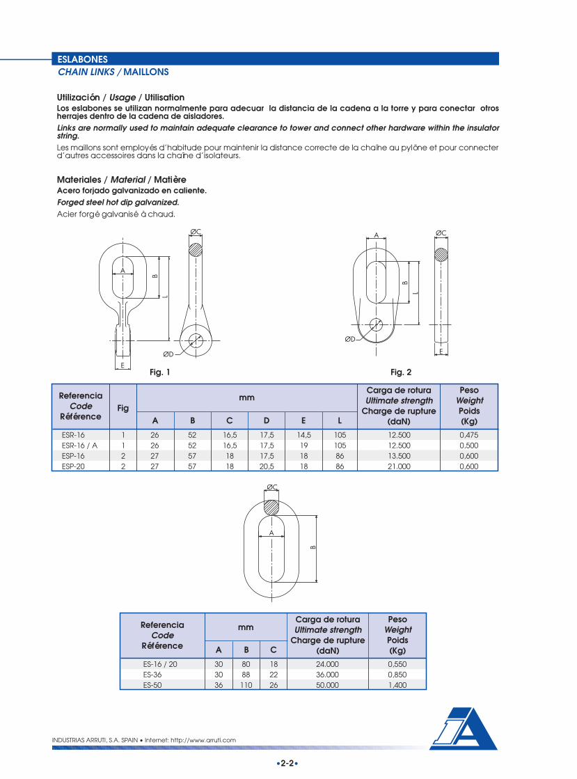
ESLABONESCHAIN LINKS / MAILLONS
Utilización / Usage / UtilisationLos eslabones se utilizan normalmente para adecuar la distancia de la cadena a la torre y para conectar otrosherrajes dentro de la cadena de aisladores.Links are normally used to maintain adequate clearance to tower and connect other hardware within the insulatorstring.Les maillons sont employés d’habitude pour maintenir la distance correcte de la chaîne au pylône et pour connecterd’autres accessoires dans la chaîne d’isolateurs.
Materiales / Material / MatièreAcero forjado galvanizado en caliente.Forged steel hot dip galvanized.Acier forgé galvanisé à chaud.
Fig. 1
•2-2•
INDUSTRIAS ARRUTI, S.A. SPAIN • Internet: http://www.arruti.com
ReferenciaCode
Référence
mmCarga de roturaUltimate strength
Charge de rupture(daN)
PesoWeightPoids(Kg)B CA
ES-16 / 20 30 80 18 24.000 0,550ES-36 30 88 22 36.000 0,850ES-50 36 110 26 50.000 1,400
LB
A
E
ØC
ØD
LB
A ØC
E
ØD
Fig. 2
B
A
ØC
ReferenciaCode
RéférenceFig
mmCarga de roturaUltimate strength
Charge de rupture(daN)
PesoWeightPoids(Kg)A B C E LD
ESR-16 1 26 52 16,5 17,5 14,5 105 12.500 0,475ESR-16 / A 1 26 52 16,5 17,5 19 105 12.500 0,500ESP-16 2 27 57 18 17,5 18 86 13.500 0,600ESP-20 2 27 57 18 20,5 18 86 21.000 0,600

ENLACES PLANOSDOUBLE EYE LINK / CONNECTEUR DROITE
Utilización / Usage / UtilisationLos enlaces se utilizan normalmente para mantener una distancia adecuada de la cadena a la torre y para conectarotros herrajes dentro de la cadena de aisladores.Links are normally used to maintain adequate clearance to tower and connect other hardware within the insulatorstring.On emploie les connecteurs pour maintenir la distance correcte de la chaîne au pylône et pour connecter d’autresaccessoires dans la chaîne d’isolateurs.
Materiales / Material / MatièreAcero galvanizado en caliente.Steel hot dip galvanized.Acier galvanisé à chaud.
ReferenciaCode
RéférenceFig
mmCarga de roturaUltimate strength
Charge de rupture(daN)
PesoWeightPoids(Kg)A C E L
ENP-16 1 30 17,5 18 100 12.000 1,200ENP-20 1 30 20,5 20 100 16.000 1,300ENP-24 1 35 24 22 100 24.000 1,700ENP-16-P 2 30 17,5 18 150 12.000 1,900ENP-20-P 2 30 20,5 20 150 16.000 2,100ENP-24-P 2 35 24 22 150 24.000 2,550
ReferenciaCode
Référence
mmCarga de roturaUltimate strength
Charge de rupture(daN)
PesoWeightPoids(Kg)A EC L
LD-150 50 24 19 100 24.000 0,700LD-150 / 20,5 45 20,5 19 100 21.000 0,700LD-150 / 17,5 45 17,5 19 100 15.000 0,700
INDUSTRIAS ARRUTI, S.A. SPAIN • Internet: http://www.arruti.com
•2-3•
L
E
Ø14
A
50
ØCLE
A
ØC
LE
AØ
ØC
Fig. 2Fig. 1

Utilización / Usage / UtilisationLas anillas bola se utilizan para conectar las cadenas de aisladores tipo caperuza-vástago. Las dimensiones delvástago están de acuerdo a la norma CEI-120, aunque bajo pedido se pueden fabricar según la norma ANSI C.29.2.Ball eyes are intended to connect ball and socket type insulator strings. Ball dimensions are in accordance to IEC-120 standard, although they may be manufactured according to ANSI C.29.2 under request.On emploie des œillets á rotule pour connecter les chaînes d’isolateurs type rotule et logement de rotule. Lesdimensions du tige sont d’accord au norme CEI-120, bien que sur commande on puisse fabriquer selon norme ANSIC.29.2
Materiales / Material / MatièreAcero forjado galvanizado en caliente.Forged steel hot dip galvanized.Acier forgé galvanisé à chaud.
(1) Añadir el valor del diámetro B / Add diameter B value / Ajouter valeur du diamètre B
ANILLAS BOLABALL EYES / OEILLETS A ROTULE
•2-4•
INDUSTRIAS ARRUTI, S.A. SPAIN • Internet: http://www.arruti.com
L
B
ØC
A
CØA
ØB
L
ØC
L
ØB
Fig. 1 Fig. 2 Fig. 3
ReferenciaCode
RéférenceFig
mmCarga de roturaUltimate strength
Charge de rupture(daN)
PesoWeightPoids(Kg)A B LC
Norma C.E.I.I.E.C. StandardNorme C.E.I.
OB-11 1 11 -- 20 11 53 5.000 0,110OB-16 1 16 -- 27 16 73 12.500 0,320AB-11 2 11 19,5 43,5 12 77 5.000 0,170AB-16 2 16 26 52 17 96 12.500 0,440OB-100 / B (1) 3 16 54 B 19 70 12.500 0,400

ANILLAS BOLA DE PROTECCIONBALL EYES FOR ARCING HORNS / OEILLETS A ROTULE POUR PROTECTIONS
Utilización / Usage / UtilisationEstas anillas bola se utilizan para conectar las cadenas de aisladores tipo caperuza-vástago y están preparadas paraacoplar protecciones. Las dimensiones del vástago están de acuerdo a la norma CEI-120, aunque bajo pedido sepueden fabricar según la norma ANSI C.29.2.These ball eyes are intended to connect ball and socket type insulator strings, and designed to be used with arcinghorns. Ball dimensions are in accordance to IEC-120 standard, although may be manufactured according to ANSIC.29.2 under request.Ces œillets sont utilisés pour connecter les chaînes d’isolateurs type rotule et logement de rotule et sont préparespour la fixation des protections. Les dimensions du tige sont d’accord au norme CEI-120, bien que sur commande onpuisse fabriquer selon norme ANSI C.29.2.
Materiales / Material / MatièreAcero forjado galvanizado en caliente.Forged steel hot dip galvanized.Acier forgé galvanisé à chaud.
INDUSTRIAS ARRUTI, S.A. SPAIN • Internet: http://www.arruti.com
Ejemplo de una anilla bola con descargadores en una cadena de suspensión.Example of a ball eje with arcing horns in a suspension string.Exemple de l'ceillet long avec protections fixes dans une chaîne de suspension.
•2-5•
ØC
BL
A
50
Ø14
F
ReferenciaCode
Référence
mmCarga de roturaUltimate strength
Charge de rupture(daN)
PesoWeightPoids(Kg)A B L FC
Norma C.E.I.I.E.C. StandardNorme C.E.I.
AB-16 P 16 30 80 16 160 47 12.500 0,750AB-20 P 20 30 80 20 170 57 18.000 1,150AB-20-P / 21 20 30 80 20 170 57 21.000 1,150AB-24-P 24 30 80 22 195 75 24.000 1,510AB-24-P / 30 24 30 80 22 195 75 30.000 1,510

HORQUILLAS BOLA EN VBALL CLEVISES TYPE V / CHAPES EN V A ROTULE
Utilización / Usage / UtilisationEstas horquillas bola se utilizan para conectar las cadenas de aisladores tipo caperuza-vástago con los herrajesasociados. Pueden ser fijadas directamente a la torre debido al doble movimiento que proporciona el tornillo curvo.El modelo largo está preparado para acoplar protecciones. Las dimensiones del vástago están de acuerdo a lanorma CEI-120, aunque bajo pedido se pueden fabricar según la norma ANSI C.29.2.These ball clevises are used to connect ball and socket type insulator strings to associated fittings. They also may beattached directly to the tower since the curve shape of the bolt provides to the string movement in two directions. Thelongest type it is designed to be used with arcing horns. Ball dimensions are in accordance to IEC-120 standard,although may be manufactured according to ANSI C.29.2 under request.Les chapes á rotule sont utilisés pour connecter les chaînes d’isolateurs type rotule et logement de rotule avec lesaccessoires associes. Ils peuvent être fixes directement au pylône á cause du double articulation donnée par leboulon courbe. Le model longe est préparé pour la fixation des protections. Les dimensions du tige sont d’accordau norme CEI-120, bien que sur commande on puisse fabriquer selon norme ANSI C.29.2
Materiales / Material / MatièreCuerpo: acero forjado galvanizado en caliente. Tornillería: acero galvanizado en caliente. Pasadores: acero inoxidableo latón.
Body: Forged steel hot dip galvanized. Bolts and nuts: steel hot dip galvanized. Cotter pin: stainless steel or brass.Corps: acier forgé galvanisé à chaud. Boulon et écrou: acier galvanisé à chaud. Goupille: acier inoxydable ou laiton.
INDUSTRIAS ARRUTI, S.A. SPAIN • Internet: http://www.arruti.com
•2-6•
LB D
ReferenciaCode
Référence
mmCarga de roturaUltimate strength
Charge de rupture(daN)
PesoWeightPoids(Kg)B D L
Norma C.E.I.I.E.C. StandardNorme C.E.I.
HB-11 11 32 M-12 64 5.000 0,310HB-16 16 35 M-16 75 12.500 0,660HB-16/18 16 35 M-18 75 12.500 0,700
ReferenciaCode
Référence
mmCarga de roturaUltimate strength
Charge de rupture(daN)
PesoWeightPoids(Kg)DB L
Norma C.E.I.I.E.C. StandardNorme C.E.I. F
HB-16-P 16 50 M-18 55 130 12.500 0,950
SECCION A-A
A ALB
F
D
22

HORQUILLAS BOLA PARALELASBALL CLEVISES / CHAPES A ROTULE
Utilización / Usage / UtilisationEstas horquillas bola se utilizan para conectar las cadenas de aisladores tipo caperuza-vástago con los yugos oherrajes asociados. El modelo largo está preparado para acoplar protecciones. Las dimensiones del vástago estánde acuerdo a la norma CEI-120, aunque bajo pedido se pueden fabricar según la norma ANSI C.29.2. These ball clevises are used to connect ball and socket type insulator strings to yoke plates or associated fittings. Thelongest type it is designed to be used with arcing horns. Ball dimensions are in accordance to IEC-120 standard,although may be manufactured according to ANSI C.29.2 under request.On emploie les chapes a rotule pour connecter les chaînes d’isolateurs type rotule et logement de rotule avec lesaccessoires associes. Le model longe est préparé pour la fixation des protections. Les dimensions du tige sont d’accordau norme CEI-120, bien que sur commande on puisse fabriquer selon norme ANSI C.29.2.
Materiales / Material / MatièreCuerpo: acero forjado galvanizado en caliente. Tornillería: acero galvanizado en caliente. Pasadores: acero inoxidableo latón.Body: Forged steel hot dip galvanized. Bolts and nuts: steel hot dip galvanized. Cotter pin: stainless steel or brass.Corps: acier forgé galvanisé à chaud. Boulon et écrou: acier galvanisé à chaud. Goupille: acier inoxydable ou laiton.
ReferenciaCode
Référence
mmCarga de roturaUltimate strength
Charge de rupture(daN)
PesoWeightPoids(Kg)A B L
Norma C.E.I.I.E.C. StandardNorme C.E.I.
HBP-16 16 26 35 M-16 72 12.500 0,510HBP-20 20 26 43 M-18 91 18.000 0,950HBP-20 / 21 20 26 43 M-22 91 21.000 1,100HBP-24 24 30 54 M-22 115 24.000 1,500HBP-24 / 30 24 30 54 M-24 115 30.000 1,600
D
ReferenciaCode
Référence
mmCarga de roturaUltimate strength
Charge de rupture(daN)
PesoWeightPoids(Kg)BA L
Norma C.E.I.I.E.C. StandardNorme C.E.I. F
HBP-16-P 16 26 50 M-16 55 135 12.500 0,900
D
•2-7•
A
LB
D
SECCION A-A
A
D
BL
F
A A
22
INDUSTRIAS ARRUTI, S.A. SPAIN • Internet: http://www.arruti.com

•2-8•
INDUSTRIAS ARRUTI, S.A. SPAIN • Internet: http://www.arruti.com
BOLAS DOBLESTWIN BALL PINS / ROTULES DOUBLES
Materiales / Material / MatièreAcero forjado galvanizado en caliente o acero inoxidable.Forged steel hot dip galvanized or stainless steel.Acier forgé galvanisé à chaud ou acier inoxydable.
ReferenciaCode
Référence
mmCarga de roturaUltimate strength
Charge de rupture(daN)
PesoWeightPoids(Kg)CB L
Norma C.E.I.I.E.C. StandardNorme C.E.I.
BB-11 11 31 11 47 5.000 0,100BB-16 16 36 16,6 62 12.500 0,175BB-20 20 45 20,5 83 18.000 0,300
GANCHOS BOLABALL HOOKS / CROCHETS
Materiales / Material / MatièreAcero forjado galvanizado en caliente.Forged steel hot dip galvanized.Acier forgé galvanisé à chaud.
B
L
ØC
Utilización / Usage / UtilisationLos ganchos bola se utilizan para conectar las cadenas de aisladores tipo caperuza-vástago directamente a la torre.Las dimensiones del vástago están de acuerdo a la norma CEI-120, aunque bajo pedido se pueden fabricar segúnla norma ANSI C.29.2.Ball hook is used as the first element for the attachment of the ball and socket type insulator strings. Ball dimensionsare in accordance to IEC-120 standard, although may be manufactured according to ANSI C.29.2 under request.On emploie des crochets pour connecter les chaînes d’isolateurs type rotule et logement de rotule directement aupylône. Les dimensions du tige sont d’accord au norme CEI-120, bien que sur commande on puisse fabriquer selonnorme ANSI C.29.2
ReferenciaCode
Référence
mmCarga de roturaUltimate strength
Charge de rupture(daN)
PesoWeightPoids(Kg)CA L
Norma C.E.I.I.E.C. StandardNorme C.E.I.
GB-16 16 22 25 25 75 12.500 0,700
B
LC
A
Ø B

Materiales / Material / MatièreCuerpo: acero galvanizado en caliente.Pasador: acero inoxidable o latón.Body: steel hot dip galvanized.Security cotter pin: stainless steel or brass.Corps: acier galvanisé à chaud.Goupille: acier inoxydable ou laiton.
Materiales / Material / MatièreCuerpo: fundición nodular galvanizado en caliente.Pasador: acero inoxidable o latón.Body: Nodular graphite cast iron, hot dip galvanized.Security cotter pin: stainless steel or brass.Corps: fonte à graphite sphéroïdal, galvanisé à chaud.Goupille: acier inoxydable ou laiton.
Utilización / Usage / UtilisationLas rótulas se utilizan para conectar las cadenas de aisladores tipo caperuza-vástago con las grapas de amarre ysuspensión. Las dimensiones del alojamiento están de acuerdo a la norma CEI-120, aunque bajo pedido se puedenfabricar según la norma ANSI C.29.2.Ball sockets are used to connect ball and socket type insulator strings to suspension and tension clamps. Socketdimensions are in accordance to IEC-120 standard, although may be manufactured according to ANSI C.29.2 underrequest.On emploie le ball socket pour connecter les chaînes d’isolateurs type rotule et logement de rotule avec les pincesd’ancrage et suspension. Les dimensions du tige sont d’accord au norme CEI-120, bien que sur commande on puissefabriquer selon norme ANSI C.29.2
Materiales / Material / MatièreCuerpo: acero forjado galvanizado en caliente.Pasador: acero inoxidable o latón.Body: Forged steel hot dip galvanized.Security cotter pin: stainless steel or brass.Corps: acier forgé galvanisé à chaud.Goupille: acier inoxydable ou laiton.
(1) Añadir la anchura de pastilla (cota E) deseada / Width E must be added to code / Ajouter la cote E sélectionnéeà la fin de la référence.
ROTULASSOCKET EYE / BALL SOCKETS A TENON
ReferenciaCode
RéférenceFig
mmCarga de roturaUltimate strength
Charge de rupture(daN)
PesoWeightPoids(Kg)A B LE
Norma C.E.I.I.E.C. StandardNorme C.E.I.
BS-11 1 11 24 36 13 52 4.000 0,220RF-16 2 16 24 40 16 62 8.000 0,600
ØD
L
E
A BL
E
A BL
E
Fig. 1
Fig. 2
INDUSTRIAS ARRUTI, S.A. SPAIN • Internet: http://www.arruti.com
•2-9•
ReferenciaCode
Référence
mmCarga de roturaUltimate strength
Charge de rupture(daN)
PesoWeightPoids(Kg)D E L
Norma C.E.I.I.E.C. StandardNorme C.E.I.
R-11 11 17,5 16 42 5.000 0,220R-16 16 17,5 16 50 12.500 0,500R-16 / M-18 16 20,5 16 50 12.500 0,500(1) R-16 / E 16 17,5 Max 45 50 12.500 0,650 Max
ROTULAS OVALESOVAL SOCKET EYE / BALL SOCKETS A OEIL OVALE

ROTULAS DE PROTECCIONSOCKET EYE / BALL SOCKETS A TENON
Utilización / Usage / UtilisationEstas rótulas se utilizan para conectar las cadenas de aisladores tipo caperuza-vástago con las grapas de amarrey suspensión, estando preparadas para acoplar protecciones. Las dimensiones del alojamiento están de acuerdoa la norma CEI-120, aunque bajo pedido se pueden fabricar según la norma ANSI C.29.2.Ball sockets are used to connect ball and socket type insulator strings to suspension and tension clamps, and designedto be used with arcing horns. Socket dimensions are in accordance to IEC-120 standard, although they may bemanufactured according to ANSI C.29.2 under request.On emploie les ball sockets pour connecter les chaînes d’isolateurs type rotule et logement de rotule avec les pincesd’ancrage et suspension. Le model longe est préparé pour la fixation des protections. Les dimensions du tige sontd’accord au norme CEI-120, bien que sur commande on puisse fabriquer selon norme ANSI C.29.2.
Materiales / Material / MatièreCuerpo: acero forjado galvanizado en caliente. Pasador: acero inoxidable o latón.Body: Forged steel hot dip galvanized. Security cotter pin: stainless steel or brass.Corps: acier forgé galvanisé à chaud. Goupille: acier inoxydable ou laiton.
ReferenciaCode
RéférenceFig
mmCarga de roturaUltimate strength
Charge de rupture(daN)
PesoWeightPoids(Kg)D LF
Norma C.E.I.I.E.C. StandardNorme C.E.I.
R-11-P 1 11 17,5 16 ---- 115 5.000 0,400R-16-P 2 16 17,5 16 67 140 12.500 0,900
Ejemplo de una rótula con descargadores tipo cuadradillo.Example of a ball socket with square hub arcing horns.Exemple du ball socket long avec protections type carré.
INDUSTRIAS ARRUTI, S.A. SPAIN • Internet: http://www.arruti.com
•2-10•
L
16
EØD
E
A A
ØD
L
F SECCION A-A
22
Fig. 1 Fig. 2
E

ROTULAS DE PROTECCIONSOCKET EYE / BALL SOCKETS A TENON
Utilización / Usage / UtilisationEstas rótulas se utilizan para conectar las cadenas de aisladores tipo caperuza-vástago con las grapas de amarre ysuspensión, estando preparadas para acoplar protecciones. Las dimensiones del alojamiento están de acuerdo ala norma CEI-120, aunque bajo pedido se pueden fabricar según la norma ANSI C.29.2.Ball sockets are used to connect ball and socket type insulator strings to suspension and tension clamps, and designedto be used with arcing horns. Socket dimensions are in accordance to IEC-120 standard, although they may bemanufactured according to ANSI C.29.2 under request.On emploie les ball sockets pour connecter les chaînes d’isolateurs type rotule et logement de rotule avec les pincesd’ancrage et suspension et sont prépares pour la fixation des protections. Les dimensions du tige sont d’accord aunorme CEI-120, bien que sur commande on puisse fabriquer selon norme ANSI C.29.2
Materiales / Material / MatièreCuerpo: acero forjado galvanizado en caliente. Pasador: acero inoxidable o latón.Body: Forged steel hot dip galvanized. Security cotter pin: stainless steel or brass.Corps: acier forgé galvanisé à chaud. Goupille: acier inoxydable ou laiton.
ReferenciaCode
Référence
mmCarga de roturaUltimate strength
Charge de rupture(daN)
PesoWeightPoids(Kg)ED L
Norma C.E.I.I.E.C. StandardNorme C.E.I. F
(1) R-16-P / E 16 17,5 Max 45 50 110 12.500 1,100 MaxR-20-P 20 20,5 22 50 105 18.000 1,550R-20-P / 21 20 23,5 22 50 105 21.000 1,600R-24-P 24 23,5 22 55 115 24.000 2,100R-24-P / 30 24 26 22 55 115 30.000 2,100
(1) Añadir la anchura de pastilla (cota E) deseada / Width E must be added to code as suffix / Ajouter la cote Esélectionnée à la fin de la référence.
Ejemplo de una rótula con descargadores colocados.Example of a ball socket with arcing horns.Exemple du ball socket long avec protections .
E
ØD
50 F
L
Ø14
INDUSTRIAS ARRUTI, S.A. SPAIN • Internet: http://www.arruti.com
•2-11•

ROTULAS HORQUILLACLEVIS SOCKET / BALL SOCKETS A CHAPE
Utilización / Usage / UtilisationLas rótulas horquilla se utilizan para conectar las cadenas de aisladores tipo caperuza-vástago con los yugos u otrosherrajes asociados. Las dimensiones del alojamiento están de acuerdo a la norma CEI-120, aunque bajo pedido sepueden fabricar según la norma ANSI C.29.2.Clevis sockets are used to connect ball and socket type insulator strings to yoke plates or associated hardware.Socket dimensions are in accordance to IEC-120 standard, although they may be manufactured according to ANSIC.29.2 under request.On utilise le ball socket a chape pour connecter les chaînes d’isolateurs type rotule et logement de rotule avec lespalonniers et d’autres accessoires associés. Les dimensions du tige sont d’accord au norme CEI-120, bien que surcommande on puisse fabriquer selon norme ANSI C.29.2
Materiales / Material / MatièreCuerpo: acero forjado galvanizado en caliente. Tornillería: acero galvanizado en caliente. Pasadores: acero inoxidableo latón.Body: Forged steel hot dip galvanized. Bolts and nuts: steel hot dip galvanized. Cotter pin: stainless steel or brass.Corps: acier forgé galvanisé à chaud. Boulon et écrou: acier galvanisé à chaud. Goupille: acier inoxydable ou laiton.
ReferenciaCode
Référence
mmCarga de roturaUltimate strength
Charge de rupture(daN)
PesoWeightPoids(Kg)BA L
Norma C.E.I.I.E.C. StandardNorme C.E.I. D
RH-16-AE 16 24 35 M-16 60 12.500 1,100RH-20-AE 20 26 45 M-18 70 18.000 1,700RH-20-AE / 21 20 26 45 M-22 70 21.000 1,750
ReferenciaCode
Référence
mmCarga de roturaUltimate strength
Charge de rupture(daN)
PesoWeightPoids(Kg)BA L
Norma C.E.I.I.E.C. StandardNorme C.E.I. D
RH-16 16 24 30 M-16 50 12.500 0,780RH-24 24 30 45 M-22 80 24.000 2,500RH-24 / 30 24 30 45 M-24 80 30.000 2,550
Pasador ocultoHidden cotter pinGoupille cachée
INDUSTRIAS ARRUTI, S.A. SPAIN • Internet: http://www.arruti.com
•2-12•
A
D
B
L
A
B
L
D

ROTULA GUARDACABOSSOCKET THIMBLE / COSSE COEUR BALL SOCKET
Utilización / Usage / UtilisationEste tipo de rótula se utiliza en conjunción con las retenciones preformadas para conductores de fase. Las dimensionesdel alojamiento están de acuerdo a la norma CEI-120.Socket thimble is used in conjunction with preformed dead ends for phase conductors. Socket dimensions are inaccordance to IEC-120 standard.On utilise le cosse coeur ball socket pour connecter les ancrages spirales pour conducteus de faiscesu. Les dimensionsdu tige sont d'accord au norme CEI-120.
Materiales / Material / MatièreCuerpo: fundición nodular galvanizada en caliente. Pasador de seguridad: acero inoxidable o latón.Body: nodular graphite cast iron, hot dip galvanized. Security cotter pin: stainless steel or brass.Corps: fonte á graphite sphéroïdal galvanisé à chaud. Goupille: acier inoxydable ou laiton.
INDUSTRIAS ARRUTI, S.A. SPAIN • Internet: http://www.arruti.com
•2-13•
D
A B
C
ReferenciaCode
Référence
mmCarga de roturaUltimate strength
Charge de rupture(daN)
PesoWeightPoids(Kg)BA D
Norma C.E.I.I.E.C. StandardNorme C.E.I. C
RG-16 16 58 22 30 50 12.500 0,850
Instalación en la retención preformadaInstallation with a preformed dead endAssemblage en l'ancrage spiral

ALARGADERAS HORQUILLACLEVIS EYE EXTENSION LINKS / RALLONGES A CHAPE-TENON
Utilización / Usage / UtilisationEstos accesorios se utilizan para alargar la cadena y, de este modo, adecuar la distancia de la cadena a la torre .Extension links are normally used to extend string and maintain adequate clearance to tower.Ces accessoires sont utilisés pour allonger la chaîne et comme ça, accommoder la distance de la chaîne au pylône.
Materiales / Material / MatièreCuerpo: acero galvanizado en caliente. Tornillos y bulones: acero galvanizado en caliente. Pasadores: acero inoxidableo latón.Body: steel hot dip galvanized. Bolt, nut and clevis pin: steel hot dip galvanized. Cotter pin: stainless steel or brass.Corps: acier galvanisé à chaud. Boulon, écrou et axe: acier galvanisé à chaud. Goupille: acier inoxydable ou laiton.
ReferenciaCode
Référence
mmCarga de roturaUltimate strength
Charge de rupture(daN)
PesoWeightPoids(Kg)EA LFB C D G
AL-75 18 26 17,5 16 12 22 40 95 7.000 0,550AL-140 18 26 17,5 16 12 22 40 140 7.000 0,750
ReferenciaCode
Référence
mmCarga de roturaUltimate strength
Charge de rupture(daN)D
Fig.
GEA B C F L
(1) AL-70 / L 1 18 26 17,5 16 12 22 40 L 7.000(1) AL-12 / L 2 18 26 20 M-16 16 22 40 L 12.000
(1) – La longitud L será definida por el cliente / Length L according to customer requirements / Longer L selon lesbesoins du client
B
ØD
AG
E
ØC
F L F
LF F
GA
B
ØD
Ø18ØC
E
B
D
AG
FLF
ØC
E
Fig. 1
Fig. 2
INDUSTRIAS ARRUTI, S.A. SPAIN • Internet: http://www.arruti.com
•2-14•

ALARGADERAS HORQUILLACLEVIS EYE EXTENSION LINKS / RALLONGES A CHAPE-TENON
Utilización / Usage / UtilisationEstos accesorios se utilizan para alargar la cadena y, de este modo, adecuar la distancia de la cadena a la torre.Extension links are normally used to extend string and maintain adequate clearance to tower.Ces accessoires sont utilisés pour allonger la chaîne et comme ça, accommoder la distance de la chaîne au pylône.
Materiales / Material / MatièreCuerpo: acero galvanizado en caliente. Tornillería: acero galvanizado en caliente. Pasadores: acero inoxidable.Body: steel hot dip galvanized. Bolts and nuts: steel hot dip galvanized. Cotter pin: stainless steel.Corps: acier galvanisé à chaud. Boulons et écrous: acier galvanisé à chaud. Goupille: acier inoxydable.
ReferenciaCode
Référence
mmCarga de roturaUltimate strength
Charge de rupture(daN)
PesoWeightPoids(Kg)EA LFB C D G
PR-150 22 45 24 M-22 20 35 70 300 15.000 4,100PR-150 / M-18 22 45 20,5 M-18 20 35 70 300 15.000 4,000PR-150 / M-16 22 45 17,5 M-16 20 35 70 300 15.000 4,000(1) PR-150 / L / D 22 45 C D 20 35 70 L 15.000 ------
(1) – Las cotas C, D y L según necesidades del cliente / Dimensions C, D and L according to customer requirements Dimensions C, D et L selon les besoins du client
Materiales / Material / MatièreCuerpo: acero forjado galvanizado en caliente. Tornillería: acero galvanizado en caliente. Pasadores: acero inoxidable.Body: forged steel hot dip galvanized. Bolts and nuts: steel hot dip galvanized. Cotter pin: stainless steel.Corps: acier forge galvanisée à chaud. Boulons et écrous: acier galvanisé à chaud. Goupille: acier inoxydable.
ReferenciaCode
Référence
mmCarga de roturaUltimate strength
Charge de rupture(daN)
PesoWeightPoids(Kg)EA LB C D
A-12 26 45 17,5 M-16 22 270 13.500 1,600A-18 26 45 20,5 M-18 22 270 18.000 1,650A-25 26 45 23,5 M-22 22 270 25.000 1,700
INDUSTRIAS ARRUTI, S.A. SPAIN • Internet: http://www.arruti.com
•2-15•
B
D
E A
FF L
ØC
G
ØC
E
L
D
A
B

Utilización / Usage / UtilisationEstos accesorios se utilizan para alargar la cadena y, de este modo, adecuar la distancia de la cadena a la torre.Extension links are normally used to extend string and maintain adequate clearance to tower.Ces accessoires sont utilisés pour allonger la chaîne et comme ça, accommoder la distance de la chaîne au pylône.
Materiales / Material / MatièreCuerpo: acero galvanizado en caliente. Tornillería: acero galvanizado en caliente. Pasadores: acero inoxidable.Body: steel hot dip galvanized. Bolts and nuts: steel hot dip galvanized. Cotter pin: stainless steel.Corps: acier galvanisé à chaud. Boulons et écrous: acier galvanisé à chaud. Goupille: acier inoxydable.
La longitud L según las necesidades del cliente / Length L according to customer requirementsLonger L selon les besoins du client
La longitud L según las necesidades del cliente / Length L according to customer requirementsLonger L selon les besoins du client
TIRANTES Y ALARGADERAS DOBLESSINGLE AND DOUBLE EXTENSION LINKS / RALLONGEST ET JUMELLES
ReferenciaCode
Référence
mmCarga de roturaUltimate strength
Charge de rupture(daN)
PesoWeightPoids
(kg / m)A CB E
TA-1 / L 45 21 17,5 15 12.500 5,500TA-2 / L 50 25 20,5 20 21.000 8,100TA-3 / L 60 30 24 20 24.000 9,900TA-4 / L 60 40 27 25 36.000 12,500
ReferenciaCode
Référence
mmCarga de roturaUltimate strength
Charge de rupture(daN)
PesoWeightPoids
(kg / m)A CB D E
ALD-1 / L 20 21 45 M-16 8 12.500 6,250ALD-2 / L 22 25 50 M-18 10 21.000 8,500ALD-3 / L 24 30 60 M-22 10 24.000 10,500ALD-4 / L 28 40 60 M-24 14 36.000 15,000
•2-16•
INDUSTRIAS ARRUTI, S.A. SPAIN • Internet: http://www.arruti.com
ØC ØC
EA
BLB
D D
B L B
CA
E
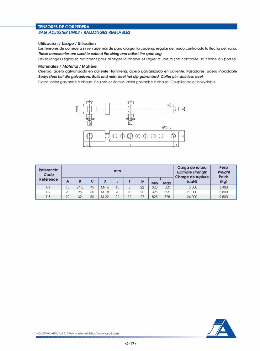
TENSORES DE CORREDERASAG ADJUSTER LINKS / RALLONGES REGLABLES
Utilización / Usage / UtilisationLos tensores de corredera sirven además de para alargar la cadena, regular de modo controlado la flecha del vano.These accessories are used to extend the string and adjust the span sag.Les rallonges réglables marchent pour allonger la chaîne et régler d’une façon contrôlée la flèche du portée.
Materiales / Material / MatièreCuerpo: acero galvanizado en caliente. Tornillería: acero galvanizado en caliente. Pasadores: acero inoxidableBody: steel hot dip galvanized. Bolts and nuts: steel hot dip galvanized. Cotter pin: stainless steel.Corps: acier galvanisé à chaud. Boulons et écrous: acier galvanisé à chaud. Goupille: acier inoxydable.
ReferenciaCode
Référence
mmCarga de roturaUltimate strength
Charge de rupture(daN)
PesoWeightPoids(Kg)B C D E F G LA Min Max
T-1 15 24,5 45 M-16 15 8 22 320 500 13.500 3,400T-2 20 25 50 M-18 20 10 25 395 625 21.000 5,800T-3 22 32 50 M-22 22 12 27 525 875 24.000 9,500
INDUSTRIAS ARRUTI, S.A. SPAIN • Internet: http://www.arruti.com
•2-17•
DD
G L B
C
ØD
E
F
A mi
n

TENSORES DE ROSCATURNBUCKLES / TENDEURS D'ANCRAGE
Utilización / Usage / UtilisationLos tensores de rosca sirven además de para alargar la cadena, regular de modo controlado la flecha del vano. Sonespecialmente utilizados en los finales de línea.These accessories are used especially in tower ends to extend the string and adjust the span sag.Les tendeurs d’ancrage marchent pour allonger la chaîne et régler d’une façon contrôlée la flèche du portée. Il sontutilisés d’habitude á la fin du ligne.
Materiales / Material / MatièreCuerpo: acero forjado galvanizado en caliente. Tornillería: acero galvanizado en caliente. Pasadores: acero inoxidable.Body: forged steel hot dip galvanized. Bolts and nuts: steel hot dip galvanized. Cotter pin: stainless steel.Corps: acier forge galvanisée à chaud. Boulons et écrous: acier galvanisé à chaud. Goupille: acier inoxydable.
ReferenciaCode
Référence
mmCarga de roturaUltimate strength
Charge de rupture(daN)
PesoWeightPoids(Kg)A B C D E L
Fig.
Min MaxTR-16 / OO 1 ------ ------ 18 ------ 24 590 910 12.500 4,000TR-16 / OH 2 17 25 18 M-16 24 610 920 12.500 4,200TR-16 / HH 3 17 25 ------ M-16 ------ 620 940 12.500 4,300
INDUSTRIAS ARRUTI, S.A. SPAIN • Internet: http://www.arruti.com
•2-18•
LB
D
A
M-1
8
ØC
ØEL
M-1
8
D
A
M-1
8
LB
ØC
ØE
Fig. 1
Fig. 2
Fig. 3

TENSORES DE ROSCATURNBUCKLES / TENDEURS D'ANCRAGE
Utilización / Usage / UtilisationLos tensores de rosca sirven además de para alargar la cadena, regular de modo controlado la flecha del vano. Sonespecialmente utilizados en los finales de línea.These accessories are used especially in tower ends to extend the string and adjust the span sag.Les tendeurs d’ancrage marchent pour allonger la chaîne et régler d’une façon contrôlée la flèche de la portée. Ilssont utilisés d’habitude á la fin du ligne.
Materiales / Material / MatièreCuerpo: acero forjado galvanizado en caliente. Tornillería: acero galvanizado en caliente. Pasadores: acero inoxidable.Body: forged steel hot dip galvanized. Bolts and nuts: steel hot dip galvanized. Cotter pin: stainless steel.Corps: acier forge galvanisée à chaud. Boulons et écrous: acier galvanisé à chaud. Goupille: acier inoxydable.
ReferenciaCode
Référence
mmCarga de roturaUltimate strength
Charge de rupture(daN)
PesoWeightPoids(Kg)A B C D E
LFig.
Min MaxTR-20 / AA 1 ------ ------ 18 ------ 23 55 685 1.015 16.500 4,700TR-20 / AH 2 24 45 18 M-18 23 55 665 995 16.500 4,800TR-20 / HH 3 24 45 ------ M-18 ------ ------ 665 995 16.500 4,800
F
INDUSTRIAS ARRUTI, S.A. SPAIN • Internet: http://www.arruti.com
•2-19•
M-2
2
L
F
E
ØC
M-2
2
D
A
BL
F
E
ØC
D
A
B
M-2
2
L
Fig. 1
Fig. 2
Fig. 3

YUGOS
PALONNIERS
YUGOS

Utilización / Usage / UtilisationEstos yugos son utilizados para formar configuraciones con doble cadena de aisladores y conductor sencillo o biencadena de aisladores simple y doble conductor. Van provistos de taladros para alojar las protecciones.Triangular yokes may be used to make two different string configurations: double insulator string – single conductoror single insulator string – twin conductor bundle. Holes for protection attachment are provided.Les palonniers sont employés pour former configurations avec chaînes doubles d’isolateurs et conducteur simple ouchaînes simples d’isolateurs et conducteur double.
Materiales / Material / MatièreAcero galvanizado en caliente.Steel hot dip galvanized.Acier galvanisé à chaud.
Esta tabla contiene tipos de fabricación normal. Bajo pedido se podrá fabricar cualquier otra referencia.This table shows the standard types; any other model is available under request.Cette table contient les types de fabrication normale. On peut fabriquer d’autres références sur commande.
YUGOS TRIANGULARESTRIANGULAR YOKE PLATES / PALONNIERS TRIANGULAIRES
ReferenciaCode
Référence
mmCarga de roturaUltimate strength
Charge de rupture(daN)
PesoWeightPoids(Kg)A C D E GB F
Y-16/330-14 90 330 17,5 17,5 16 25 25 14.000 4,200Y-16/400-14 90 400 17,5 17,5 16 25 25 14.000 5,000Y-16/450-14 90 450 17,5 17,5 16 25 25 14.000 5,600Y-16/330-21 90 330 17,5 20,5 18 30 25 21.000 4,800Y-16/400-21 90 400 17,5 20,5 18 30 25 21.000 5,800Y-16/450-21 90 450 17,5 20,5 18 30 25 21.000 6,500Y-16/330-22 90 330 17,5 22 18 30 25 22.000 4,800Y-16/400-22 90 400 17,5 22 18 30 25 22.000 5,800Y-16/450-22 90 450 17,5 22 18 30 25 22.000 6,500Y-16/330-25 90 330 17,5 23,5 22 35 25 25.000 6,100Y-16/400-25 90 400 17,5 23,5 22 35 25 25.000 7,300Y-16/450-25 90 450 17,5 23,5 22 35 25 25.000 8,100Y-20/400-21 90 400 20,5 20,5 22 30 30 21.000 7,900Y-20/450-21 90 450 20,5 20,5 22 30 30 21.000 8,600Y-20/400-25 90 400 20,5 23,5 22 45 30 25.000 8,400Y-20/450-25 90 450 20,5 23,5 22 45 30 25.000 9,300Y-20/400-36 90 400 20,5 27 22 60 30 36.000 9,000Y-20/450-36 90 450 20,5 27 22 60 30 36.000 10,000Y-24/400-36 100 400 23,5 27 22 60 35 36.000 10,000Y-24/450-36 100 450 23,5 27 22 60 35 36.000 11,200Y-24/400-50 100 400 23,5 35 26 60 35 50.000 11,900Y-24/450-50 100 450 23,5 35 26 60 35 50.000 13,200
•3-1•
INDUSTRIAS ARRUTI, S.A. SPAIN • Internet: http://www.arruti.com
50Ø14 A
ØD
ØC
E
B
20
G
F

YUGOS TRIANGULARES ANTICORONACORONA FREE YOKE PLATES / PALONNIERS TYPE ANTI-EFFLUVE
Utilización / Usage / UtilisationEstos yugos son utilizados para formar configuraciones con doble cadena de aisladores y conductor sencillo o biencadena de aisladores simple y doble conductor. Su forma especial está pensada para evitar el efecto corona. Vanprovistos de taladros para alojar las protecciones.Triangular yokes may be used to make two different string configurations: double insulator string – single conductoror single insulator string – twin conductor bundle. Its shape it is especially design to reduce the corona effect in thestring. Holes for protection attachment are provided.Les palonniers sont employés pour former configurations avec chaînes doubles d’isolateurs et conducteur simple ouchaînes simples d’isolateurs et conducteur double. Ce dessin est anti effluve.
Materiales / Material / MatièreAcero galvanizado en caliente.Steel hot dip galvanized.Acier galvanisé à chaud.
Esta tabla contiene tipos de fabricación normal. Bajo pedido se podrá fabricar cualquier otra referencia.This table shows the standard types; any other model is available under request.
Cette table contient les types de fabrication normale. On peut fabriquer d’autres références sur commande.
ReferenciaCode
Référence
mmCarga de roturaUltimate strength
Charge de rupture(daN)
PesoWeightPoids(Kg)A D E G JC H
YF-16/400-14 110 400 17,5 17,5 18 25 25 17,5 60 14.000 5,600YF-16/400-21 110 400 17,5 20,5 18 30 25 17,5 60 21.000 5,600YF-16/400-25 110 400 17,5 23,5 22 35 25 17,5 60 25.000 6,800YF-20/400-21 110 400 20,5 20,5 22 30 30 20,5 60 21.000 6,800YF-20/400-25 110 400 20,5 23,5 22 45 30 20,5 60 25.000 6,800YF-20/400-36 110 400 20,5 27 22 60 30 20,5 60 36.000 6,800YF-24/400-36 120 400 23,5 27 22 60 35 23,5 60 36.000 8,500
B F
INDUSTRIAS ARRUTI, S.A. SPAIN • Internet: http://www.arruti.com
F
ØDE
ØH
50
Ø14
J
20
G
B
ØC
A
•3-2•

ENLACES TRIANGULARESTRIANGULAR YOKE PLATES / TRIANGLE DE DOUBLEMENT
Utilización / Usage / UtilisationEstos yugos están pensados para aplicaciones especiales con distancias entre centros menores de 250 mm. Bajopedido pueden ir provistos de taladros para alojar las protecciones.These kind of triangular yokes are designed for applications where spacing is less than 250 mm. Holes for protectionattachment are provided under request.Le dessin des palonniers est propre pour distances plus petites que 250 mm. Sur commande, ils peuvent être équipésdes trous pour la fixation des protections.
Materiales / Material / MatièreAcero galvanizado en caliente.Steel hot dip galvanized.Acier galvanisé à chaud.
ReferenciaCode
Référence
mmCarga de roturaUltimate strength
Charge de rupture(daN)
PesoWeightPoids(Kg)A D E GCB F
ET-16 70 100 17,5 20,5 18 25 25 12.000 1,600ET-20 70 100 20,5 20,5 20 30 30 18.000 2,100ET-24 70 100 26 26 20 35 35 24.000 2,400ET-16-A 90 120 17,5 20,5 18 25 25 12.000 2,400ET-20-A 90 120 20,5 20,5 20 30 30 18.000 3,000ET-24-A 90 120 26 26 20 35 35 24.000 3,700ET-20-V 90 180 20,5 20,5 20 30 30 18.000 3,600ET-24-V 90 180 20,5 23,5 20 30 30 24.000 3,600YVS-16 100 200 17,5 17,5 16 25 25 14.000 3,000YVS-16/100 100 100 17,5 17,5 16 25 25 14.000 1,800
Esta tabla contiene tipos de fabricación normal. Bajo pedido se podrá fabricar cualquier otra referencia.This table shows the standard types; any other model is available under request.Cette table contient les types de fabrication normale. On peut fabriquer d’autres références sur commande.
INDUSTRIAS ARRUTI, S.A. SPAIN • Internet: http://www.arruti.com
•3-3•
G
F
ØDE
ØC
AB

YUGOS SEPARADORESRECTANGULAR YOKES / PALONNIERS RECTANGULAIRES
Utilización / Usage / UtilisationEstos yugos son utilizados para formar configuraciones con doble cadena de aisladores y conductor dúplex. Vanprovistos de taladros para alojar las protecciones.These rectangular yokes are used with a double insulator string and twin conductor bundle. Holes for protectionattachment are provided.Les palonniers sont employés pour former configurations avec chaînes doubles d’isolateurs et conducteur double.Ils peuvent être équipés des trous pour la fixation des protections.
Materiales / Material / MatièreAcero galvanizado en caliente.Steel hot dip galvanized.Acier galvanisé à chaud.
ReferenciaCode
Référence
mmCarga de roturaUltimate strength
Charge de rupture(daN)
PesoWeightPoids(Kg)A D E GCB F
YL-1 55 330 17,5 17,5 16 25 25 50 28.000 2,900YL-1 / 1 55 330 17,5 20,5 16 30 25 50 28.000 3,000YL-2 55 400 17,5 17,5 16 25 25 50 28.000 3,300YL-2 / 1 55 400 17,5 20,5 16 30 25 50 28.000 3,400YL-2 / 450 55 450 17,5 17,5 16 25 25 50 28.000 3,700YL-3 75 400 20,5 20,5 22 30 30 60 36.000 6,400YL-3 / 450 75 450 20,5 20,5 22 30 30 60 36.000 7,000YL-4 65 400 23,5 23,5 22 35 35 60 48.000 6,400YL-4 / 450 65 450 23,5 23,5 22 35 35 60 48.000 6,900
H
Esta tabla contiene tipos de fabricación normal. Bajo pedido se podrá fabricar cualquier otra referencia.This table shows the standard types; any other model is available under request.Cette table contient les types de fabrication normale. On peut fabriquer d’autres références sur commande.
INDUSTRIAS ARRUTI, S.A. SPAIN • Internet: http://www.arruti.com
•3-4•
B
50
Ø14 ØD
ØC
AF
GE
Ø23,5
H

YUGOS PARA SUSPENSION EN "V""V" SUSPENSION YOKE PLATES / PALONNIERS TYPE SUSPENSION "V"
Utilización / Usage / UtilisationEstos yugos son utilizados para formar configuraciones con doble cadena de aisladores en “V” y conductor dúplexen suspensión. Van provistos de taladros para alojar las protecciones.These yokes are used with a double “V” insulator string and twin conductor bundle in suspension arrangements. Holesfor protection attachment are provided.Ces palonniers sont employés pour former configurations avec chaînes doubles d’isolateurs en “V” et conducteurdouble. Ils sont équipés des trous pour la fixation des protections.
Materiales / Material / MatièreAcero galvanizado en caliente.Steel hot dip galvanized.Acier galvanisé à chaud.
ReferenciaCode
Référence
mmCarga de roturaUltimate strength
Charge de rupture(daN)
PesoWeightPoids(Kg)A D E GCB F
YVD-16 / 400 120 400 17,5 17,5 18 25 25 28.000 7,500YVD-16 / 450 120 450 17,5 17,5 18 25 25 28.000 8,500YVD-20 / 400 120 400 17,5 20,5 22 30 25 36.000 9,500YVD-20 / 450 120 450 17,5 20,5 22 30 25 36.000 10,800YVD-24 / 400 120 400 17,5 23,5 22 45 30 48.000 11,000YVD-24 / 450 120 450 17,5 23,5 22 45 30 48.000 11,500
Esta tabla contiene tipos de fabricación normal. Bajo pedido se podrá fabricar cualquier otra referencia.This table shows the standard types; any other model is available under request.Cette table contient les types de fabrication normale. On peut fabriquer d’autres références sur commande.
B
F
G
35
50
ØD ØD
Ø14
45° ØC
A
E
INDUSTRIAS ARRUTI, S.A. SPAIN • Internet: http://www.arruti.com
•3-5•

YUGOS DOBLES TRIANGULARESTRIANGULAR YOKE PLATES / PALONNIERS A TRIPLE CHAPE
Utilización / Usage / UtilisationEstos yugos, de utilización similar a los anteriormente presentados, están pensados para trabajar con herrajes deltipo pastilla.These kind of triangular yokes, for the same use of the previous models, are intended to work with tongue type fittings.Ces palonniers, qui s’assemblent aux derniers, ont été dessines pour accoupler accessoires a tenon.
Materiales / Material / MatièreCuerpo: acero galvanizado en caliente. Tornillos y bulones: acero galvanizado en caliente. Pasadores: acero inoxidableo latón.Body: steel hot dip galvanized. Bolt, nut and clevis pin: steel hot dip galvanized. Cotter pin: stainless steel or brass.Corps: acier galvanisé à chaud. Boulon, écrou et axe: acier galvanisé à chaud. Goupille: acier inoxydable ou laiton.
ReferenciaCode
Référence
mmCarga de roturaUltimate strength
Charge de rupture(daN)
PesoWeightPoids(Kg)A D ECB
YD 85 270 18 16 6 9.000 2,700YD-300 85 300 18 16 6 12.500 3,000
ReferenciaCode
Référence
mmCarga de roturaUltimate strength
Charge de rupture(daN)
PesoWeightPoids(Kg)A D E GCB F
BT-150 70 400 22 M-22 10 35 25 24.000 7,200BT-150 / 400/ M-16 70 400 22 M-16 10 35 25 15.000 6,600BT-150 / 330/ M-16 70 330 22 M-16 10 35 25 15.000 5,600
Esta tabla contiene tipos de fabricación normal. Bajo pedido se podrá fabricar cualquier otra referencia.This table shows the standard types; any other model is available under request.Cette table contient les types de fabrication normale. On peut fabriquer d’autres références sur commande.
INDUSTRIAS ARRUTI, S.A. SPAIN • Internet: http://www.arruti.com
•3-6•
B
AØ
D
C
E
F
Ø14
A
70
B
G
D
CE

Utilización / Usage / UtilisationEstos yugos son utilizados para formar configuraciones con doble cadena de aisladores y conductor dúplex, estandopensados para trabajar con herrajes del tipo pastilla.These rectangular yokes are used with a double insulator string and twin conductor bundle and they are intended towork with tongue type fittings.Ces palonniers rectangulaires sont employés pour former configurations avec chaînes doubles d’isolateurs etconducteur double et ont été dessines pour accoupler accessoires a tenon.
Materiales / Material / MatièreCuerpo: acero galvanizado en caliente. Tornillos: acero galvanizado en caliente. Pasadores: acero inoxidable.Body: steel hot dip galvanized. Bolts and nuts: steel hot dip galvanized. Cotter pin: stainless steel.Corps: acier galvanisé à chaud. Boulon et écrou: acier galvanisé à chaud. Goupille: acier inoxydable.
Esta tabla contiene tipos de fabricación normal. Bajo pedido se podrá fabricar cualquier otra referencia.This table shows the standard types; any other model is available under request.Cette table contient les types de fabrication normale. On peut fabriquer d’autres références sur commande.
YUGOS SEPARADORES DOBLESRECTANGULAR YOKE PLATES / PALONNIERS A QUADRUPLE CHAPE
ReferenciaCode
Référence
mmCarga de roturaUltimate strength
Charge de rupture(daN)
PesoWeightPoids(Kg)A D ECB F
BR4-150 / 400 70 400 22 M-22 10 25 36.000 9,700BR4-150 / 400 / M16 70 400 22 M-16 10 25 28.000 9,000BR4-150 / 330 / M16 70 330 22 M-16 10 25 28.000 7,700
INDUSTRIAS ARRUTI, S.A. SPAIN • Internet: http://www.arruti.com
•3-7•
D
B
70
Ø14
F
AC
E

Utilización / Usage / UtilisationEstos yugos se utilizan en la formación de cadenas de amarre para conductor triple. Van provistos de taladros paraalojar las protecciones.These yokes are used to anchor triple conductor bundles in tension arrangements. Holes for protection attachmentare provided.On emploie ces palonniers dans la formation des chaînes d’ancrage pour conducteur triple. Ils sont équipés de troupour la fixation des protections.
Materiales / Material / MatièreAcero galvanizado en caliente.Steel hot dip galvanized.Acier galvanisé à chaud.
Esta tabla contiene tipos de fabricación normal. Bajo pedido se podrá fabricar cualquier otra referencia.This table shows the standard types; any other is available under request.Cette table contient les types de fabrication normale. On peut fabriquer d’autres références sur commande.
YUGOS TRIPLES DE AMARREYOKES FOR TRIPLE STRAIN BUNDLE / PALONNIERS POUR FAISCEAUX TRIPLE
ReferenciaCode
Référence
mmCarga de roturaUltimate strength
Charge de rupture(daN)
PesoWeightPoids(Kg)A F GCB JD E H
YTA-3-16-36 / 400 400 230 17,5 27 18 25 25 50 125 36.000 16,000YTA-3-20-36 / 400 400 230 20,5 27 18 30 30 50 125 36.000 16,000YTA-3-24-50 / 400 400 230 23,5 35 22 35 35 60 125 50.000 19,000
A
E
E
A
J
H
ØD
B
ØC
F
Ø 1 4 50
ØC
G
INDUSTRIAS ARRUTI, S.A. SPAIN • Internet: http://www.arruti.com
•3-8•

YUGOS TRIPLES DE SUSPENSIONYOKES FOR TRIPLE SUSPENSION BUNDLE / PALONNIERS POUR FAISCEAUX TRIPLE
Utilización / Usage / UtilisationEstos yugos se utilizan en la formación de suspensiones con cadenas de aisladores sencilla o doble para conductortriple. Van provistos de taladros para alojar las protecciones.These yokes are used to suspend single or double insulator strings with triple conductor bundles. Holes for protectionattachment are provided.On emploie ces palonniers dans la formation de suspensions avec chaînes d’isolateurs simples ou doubles pourconducteur triple. Ils sont équipés de trou pour la fixation des protections.
Materiales / Material / MatièreAcero galvanizado en caliente.Steel hot dip galvanized.Acier galvanisé à chaud.
ReferenciaCode
Référence
mmCarga de roturaUltimate strength
Charge de rupture(daN)
PesoWeightPoids(Kg)E FBA C D H
Fig.G
YTS-3-16-14 / 400 1 400 60 17,5 17,5 18 25 30 50 14.000 11,000YTS-3-20-21 / 400 1 400 60 20,5 17,5 20 25 35 50 21.000 12,000YTS-3-24-25 / 400 1 400 60 23,5 17,5 22 25 45 50 25.000 13,500YTSD-3-16-28 / 400 2 400 60 17,5 17,5 18 25 25 50 28.000 12,500YTSD-3-20-42 / 400 2 400 60 20,5 17,5 20 25 30 50 42.000 14,000YTSD-3-24-48 / 400 2 400 60 23,5 17,5 22 25 35 50 48.000 15,000
Esta tabla contiene tipos de fabricación normal. Bajo pedido se podrá fabricar cualquier otra referencia.This table shows the standard types; any other is available under request.Cette table contient les types de fabrication normale. On peut fabriquer d’autres références sur commande.
A
ØC
ØD
GH
50
Ø14 B
Ø25
ØD
F
E
A
ØD
F
A
Ø25
Ø 1 4
GH
ØC
Ø D
GB
F
5 0
Ø25
A
E
Ø D
F
INDUSTRIAS ARRUTI, S.A. SPAIN • Internet: http://www.arruti.com
•3-9•
Fig. 1 Fig. 2

Utilización / Usage / UtilisationEstos yugos se utilizan en la formación de suspensiones con cadenas de aisladores en “V” para conductor triple. Vanprovistos de taladros para alojar las protecciones.These yokes are used to suspend “V” insulator strings with triple conductor bundles. Holes for protection attachmentare provided.Les palonniers sont employés pour fomer suspensions avec chaînes d'isolateurs en “V” pour conducteur triple . Ils sontéquipés de trou pour la fixation des protections.
Materiales / Material / MatièreAcero galvanizado en caliente.Steel hot dip galvanized.Acier galvanisé à chaud.
Esta tabla contiene tipos de fabricación normal. Bajo pedido se podrá fabricar cualquier otra referencia.This table shows the standard types; any other is available under request.Cette table contient les types de fabrication normale. On peut fabriquer d’autres références sur commande.
YUGOS TRIPLES DE SUSPENSIONYOKES FOR TRIPLE SUSPENSION BUNDLE / PALONNIERS POUR FAISCEAUX TRIPLE
ReferenciaCode
Référence
mmPeso
WeightPoids(Kg)A F GCB JD E H
YTSV-3-16-28 / 400 400 60 17,5 17,5 18 25 25 50 200 28.000 11,000YTSV-3-20-42 / 400 400 60 20,5 17,5 20 25 30 50 200 42.000 12,000YTSV-3-24-48 / 400 400 60 23,5 17,5 22 25 35 50 200 48.000 13,000
Carga de roturaUltimate strength
Charge de rupture(daN)
A
J
Ø C
ØDBHG
5 0Ø 1 4
Ø D
F
Ø 2 5
E
ØD
F
A
INDUSTRIAS ARRUTI, S.A. SPAIN • Internet: http://www.arruti.com
•3-10•
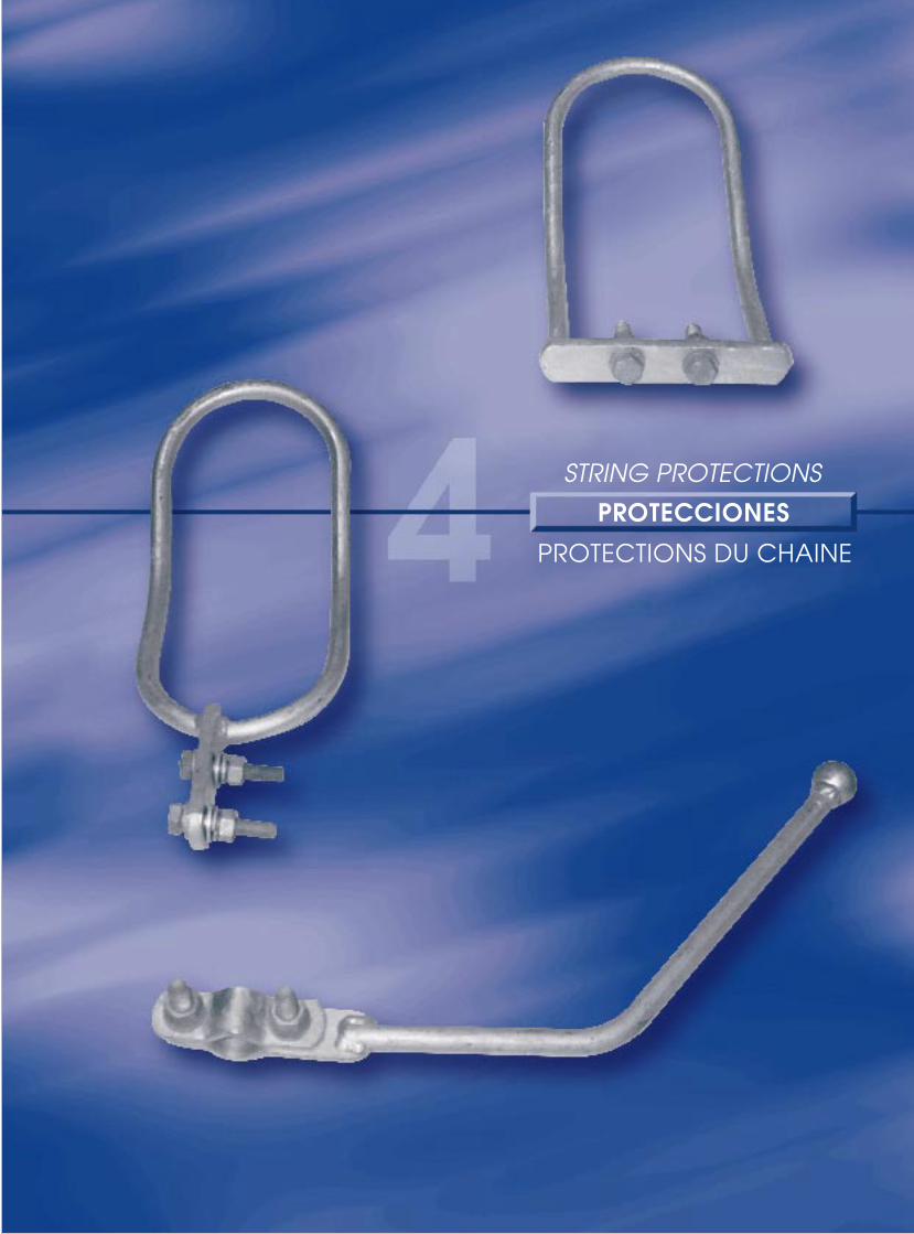
PROTECCIONES
PROTECTIONS DU CHAINE
STRING PROTECTIONS

INTRODUCCIONINTRODUCTION / INTRODUCTION
INDUSTRIAS ARRUTI, S.A. SPAIN • Internet: http://www.arruti.com
•4-1•
Las soluciones de las protecciones contra el arco de potencia y el efecto corona en las cadenas de aisladores sonmuy variadas. Ello da lugar a la existencia de un gran número de piezas en el mercado. Básicamente están diseñadaspara:• Reducir al máximo el efecto corona y los niveles de radio interferencia, asegurando la repartición del gradiente
de potencial a lo largo de la cadena.• Soportar sin daños graves los arcos de potencia que se generan en las cadenas de aisladores.Por esta última razón, se fabrican de acero galvanizado en caliente, en general de redondos macizos, salvo en lasraquetas de 400 kV en las que emplea tubo.Las dimensiones son las normales de stock, por lo que si se precisan otras distintas con el fin de conseguir determinadasdistancias espinterométricas, será necesario emplear piezas especiales que se suministrarán bajo pedido
Many and varied are the solutions for protections against power flashovers and RIV corona levels on insulator stringsto be found on the market. They are basically designed for:
• Reduce to the maximum RIV and corona levels, ensuring an equal potential gradient along insulators.• Withstand without severe damages power arcs in insulator strings.For this later reason, they are totally made of hot dip galvanised steel, generally of solid bars, except for the 400 kVracquets where tube is used.Dimensions are the standard in stock. For expressed horn gap, it is necessary special protections, also available underrequest.
Las solutions des protections contre l’arc de puissance et l’effet couronne aux chaînes d’isolateurs sont très différents.Ce pour ça qu’il existe un grand nombre de pièces dans le marché. Fondamentalement ils sont dessinés pour :• Réduire au maximum l’effet couronne et les niveaux de radio interférence, qui assure la répartition du potentiel
le long de la chaîne.• Supporter sans damages graves les arcs électriques que se produisent aux chaînes d’isolateurs.Pour cette dernière raison, ils sont fabriqués en acier galvanisé en chaud, en général en acier de section circulaire,sauf les raquettes de 400 kV dans lesquelles on emploie tube.Les dimensions sont les normales de stock,. Si on a besoin d’autres mesures a fin de obtenir des distances déterminésentre les protections, il sera nécessaire employer des pièces spéciaux qui seront fournis sur commande.
Ejemplo de aplicación de las protecciones.Example of protection application.Exemple d'application des protections.

DESCARGADORESARCING HORNS / CORNES
•4-2•
Fig. 1
INDUSTRIAS ARRUTI, S.A. SPAIN • Internet: http://www.arruti.com
Materiales / Material / MatièreCuerpo: acero galvanizado en caliente. Tornillería: acero galvanizado en caliente.Body: steel hot dip galvanized. Bolts and nuts: steel hot dip galvanized.Corps: acier galvanisé à chaud. Boulons et écrous: acier galvanisé à chaud.
ReferenciaCode
Référence
mmTensiónVoltageTension
(kV)
PesoWeightPoids(Kg)
Fig.DL B
D-30 / 10 1 300 100 16 ---- ≤ 66 0,700D-30 / 18 1 300 180 16 ---- ≤ 66 0,800D-35 / 11 1 350 110 16 ---- 132 0,750D-35 / 19 1 350 195 16 ---- 132 0,850D-37 / 11 2 375 110 16 30 220 0,900D-37 / 19 2 375 195 16 30 220 1,000D-37 / 19 / 20 2 375 195 20 35 400 1,500
H
Fig. 2
30
50
5L
H
ØD
EJE DE LACADENASTRING AXIS
M-12
EJE DE LACADENASTRING AXIS
305
LH
ØD
ØB
M-1250

DESCARGADORESARCING HORNS / CORNES
•4-3•
Fig. 1
INDUSTRIAS ARRUTI, S.A. SPAIN • Internet: http://www.arruti.com
Materiales / Material / MatièreCuerpo: acero galvanizado en caliente. Tornillería: acero galvanizado en caliente.Body: steel hot dip galvanized. Bolts and nuts: steel hot dip galvanized.Corps: acier galvanisé à chaud. Boulons et écrous: acier galvanisé à chaud.
Fig. 2
H
L
Ø D60
30
EJE DE LACADENASTRING AXIS
22
H
L
ØD
ØB
60
30
EJE DE LACADENASTRING AXIS
22
ReferenciaCode
Référence
mmTensiónVoltageTension
(kV)
PesoWeightPoids(Kg)
Fig.DL BH
DC-30 / 10 1 300 100 16 ---- ≤ 66 0,800DC-30 / 18 1 300 180 16 ---- ≤ 66 0,900DC-35 / 11 1 350 110 16 ---- 132 0,900DC-35 / 19 1 350 195 16 ---- 132 0,950DC-37 / 11 2 375 110 16 30 220 1,100DC-37 / 19 2 375 195 16 30 220 1,150

Fig. 1
LH
ØD
50710
30
L
H
ØD
50710
30
ØB
EJE DE LA CADENASTRING AXIS
M-12 M-12
EJE DE LA CADENASTRING AXIS
Fig. 2
DESCARGADORESARCING HORNS / CORNES
•4-4•
INDUSTRIAS ARRUTI, S.A. SPAIN • Internet: http://www.arruti.com
Materiales / Material / MatièreCuerpo: acero galvanizado en caliente. Tornillería: acero galvanizado en caliente.Body: steel hot dip galvanized. Bolts and nuts: steel hot dip galvanized.Corps: acier galvanisé à chaud. Boulons et écrous: acier galvanisé à chaud.
ReferenciaCode
Référence
mmTensiónVoltageTension
(kV)
PesoWeightPoids(Kg)
Fig.DH BL
DI-30 / 10 1 300 100 16 ---- ≤ 66 0,850DI-30 / 13 1 300 130 16 ---- ≤ 66 0,900DI-30 / 18 1 300 180 16 ---- ≤ 66 0,950DI-30 / 22 1 300 220 16 ---- ≤ 66 1,000DI-35 / 11 1 350 110 16 ---- 132 0,900DI-35 / 13 1 350 130 16 ---- 132 0,950DI-35 / 19 1 350 195 16 ---- 132 1,000DI-35 / 24 1 350 240 16 ---- 132 1,100DI-37 / 11 2 375 110 16 30 220 1,050DI-37 / 13 2 375 130 16 30 220 1,100DI-37 / 19 2 375 195 16 30 220 1,150DI-37 / 24 2 375 240 16 30 220 1,200DI-37 / 19 / 20 2 375 195 20 35 400 1,350DI-37 / 24 / 20 2 375 240 20 35 400 1,800

DESCARGADORES REGULABLESADJUSTABLE ARCING HORNS / CORNES REGLABLES
•4-5•
INDUSTRIAS ARRUTI, S.A. SPAIN • Internet: http://www.arruti.com
Materiales / Material / MatièreCuerpo: acero galvanizado en caliente. Tornillería: acero galvanizado en caliente.Body: steel hot dip galvanized. Bolts and nuts: steel hot dip galvanized.Corps: acier galvanisé à chaud. Boulons et écrous: acier galvanisé à chaud.
Las dimensiones de estos descargadores dependen de las características geométricas y eléctricas de la cadena.Consultar con el Departamento Técnico.Dimensions of these adjustable arcing horns depend on the geometry and electrical characteristics of the string.Contact with our Technical Department.Les dimensions de ces cornes réglables dépendent des caractéristiques géométriques et électriques de la chaîne.Consulter avec le Département Technique.
90 50
45
H
L
R
Ø14
ØB
M
ØD
22
30
50
60
EJE DE LA CADENASTRING AXIS

DESCARGADORES REGULARESADJUSTABLE ARCING HORNS / CORNES REGLABLES
•4-6•
INDUSTRIAS ARRUTI, S.A. SPAIN • Internet: http://www.arruti.com
Materiales / Material / MatièreCuerpo: acero galvanizado en caliente. Tornillería: acero galvanizado en caliente.Body: steel hot dip galvanized. Bolts and nuts: steel hot dip galvanized.Corps: acier galvanisé à chaud. Boulons et écrous: acier galvanisé à chaud.
Las dimensiones de estos descargadores dependen de las características geométricas y eléctricas de la cadena.Consultar con el Departamento Técnico.Dimensions of these adjustable arcing horns depend on the geometry and electrical characteristics of the string.Contact with our Technical Department.Les dimensions de ces cornes réglables dépendent des caractéristiques géométriques et électriques de la chaîne.Consulter avec le Département Technique.
70
45
16
L
H
Ø25
Ø25
70
16
45
Ø25
L
H
Tipo / TypeHDR-25
Tipo / TypeHDF-25

RAQUETASRACQUETS / RAQUETTES
•4-7•
INDUSTRIAS ARRUTI, S.A. SPAIN • Internet: http://www.arruti.com
Materiales / Material / MatièreCuerpo: acero galvanizado en caliente. Tornillería: acero galvanizado en caliente.Body: steel hot dip galvanized. Bolts and nuts: steel hot dip galvanized.Corps: acier galvanisé à chaud. Boulons et écrous: acier galvanisé à chaud.
ReferenciaCode
Référence
mmTensiónVoltageTension
(kV)
PesoWeightPoids(Kg)H DL
R-30 / 10 300 100 16 ≤ 66 1,600R-30 / 16 300 160 16 ≤ 66 1,750R-30 / 22 300 220 16 ≤ 66 1,900R-35 / 16 350 160 16 132 1,900R-35 / 22 350 220 16 132 2,000R-37 / 22 375 220 20 220 3,000
10
140
50
H
ØD
L
M-12
EJE DE LA CADENASTRING AXIS

RAQUETASRACQUETS / RAQUETTES
•4-8•
INDUSTRIAS ARRUTI, S.A. SPAIN • Internet: http://www.arruti.com
Materiales / Material / MatièreCuerpo: acero galvanizado en caliente. Tornillería: acero galvanizado en caliente.Body: steel hot dip galvanized. Bolts and nuts: steel hot dip galvanized.Corps: acier galvanisé à chaud. Boulons et écrous: acier galvanisé à chaud.
ReferenciaCode
Référence
TensiónVoltageTension
(kV)
PesoWeightPoids(Kg)
Fig.
RA-37 / 16 1 220 - 400 3,300RA-50 /28 2 220 - 400 7,250
Fig. 1
Fig. 2
30190
50
375
160 360
M12
10
EJE DE LA CADENASTRING AXIS
Ø20
EJE DE LA CADENASTRING AXIS
575
10
250
60
50
280
50X3
500
M12

RAQUETASRACQUETS / RAQUETTES
•4-9•
INDUSTRIAS ARRUTI, S.A. SPAIN • Internet: http://www.arruti.com
Materiales / Material / MatièreCuerpo: acero galvanizado en caliente. Tornillería: acero galvanizado en caliente.Body: steel hot dip galvanized. Bolts and nuts: steel hot dip galvanized.Corps: acier galvanisé à chaud. Boulons et écrous: acier galvanisé à chaud.
ReferenciaCode
Référence
mmTensiónVoltageTension
(kV)
PesoWeightPoids(Kg)
Fig.DL AH
RI-30 / 10 1 300 100 16 156 ≤ 66 1,500RI-30 / 16 1 300 160 16 156 ≤ 66 1,700RI-35 / 10 1 350 100 16 156 132 1,700RI-35 / 16 1 350 160 16 156 132 1,800RI-37 / 16 1 375 160 20 164 220 2,500RI-37 / 22 1 375 220 20 164 220 2,800RI-37 / 16 / 30 1 375 160 20 300 220 - 400 3,100RIC-30 / 10 2 300 100 16 156 ≤ 66 1,500RIC-30 / 16 2 300 160 16 156 ≤ 66 1,700RIC-35 / 10 2 350 100 16 156 132 1,700RIC-35 / 16 2 350 160 16 156 132 1,800RIC-37 / 16 2 375 160 20 164 220 2,500RIC-37 / 22 2 375 220 20 164 220 2,800RIC-37 / 16 / 30 2 375 160 20 300 220 - 400 3,100
EJE DE LACADENASTRING AXIS
H A
30
8
50
10
ØD
M12
L
L
30
60
H A
ØD
10
M12
22
Fig. 1 Fig. 2

RAQUETA TIPO ANILLOTYPE RING RACQUETS / RAQUETTES TYPE ANNEAUX
•4-10•
INDUSTRIAS ARRUTI, S.A. SPAIN • Internet: http://www.arruti.com
Materiales / Material / MatièreCuerpo: acero galvanizado en caliente. Tornillería: acero galvanizado en caliente.Body: steel hot dip galvanized. Bolts and nuts: steel hot dip galvanized.Corps: acier galvanisé à chaud. Boulons et écrous: acier galvanisé à chaud.
Las dimensiones de estas raquetas de anillo dependen de las características geométricas y eléctricas de la cadena.Consultar con el Departamento Técnico.
Dimensions of these racquets depend on the geometry and electrical characteristics of the string. Contact with ourTechnical Department.
Les dimensions de ces raquettes dépendent des caractéristiques géométriques et électriques de la chaîne. Consulteravec le Département Technique.
ØD
ød
H
L
A
M12

AROS EQUIPOTENCIALESGRADING RINGS / ANNEAUX
•4-11•
INDUSTRIAS ARRUTI, S.A. SPAIN • Internet: http://www.arruti.com
Materiales / Material / MatièreCuerpo: acero galvanizado en caliente. Tornillería: acero galvanizado en caliente.Body: steel hot dip galvanized. Bolts and nuts: steel hot dip galvanized.Corps: acier galvanisé à chaud. Boulons et écrous: acier galvanisé à chaud.
Las dimensiones de estos aros dependen de las características geométricas y eléctricas de la cadena. Consultar conel Departamento Técnico.
Dimensions of these grading rings depend on the geometry and electrical characteristics of the string. Contact with ourTechnical Department.
Les dimensions de ces raquettes dépendent des caractéristiques géométriques et électriques de la chaîne. Consulteravec le Département Technique.
50
ØDH
ødM12

GRAPAS DE SUSPENSION Y DE AMARRE PARACONDUCTORES DE ALUMINIO
CONTRAPESOS Y VARILLAS DE PROTECCIÓN
PINCES DE SUSPENSION ET D'ANCRAGEPOUR CONDUCTEURS D'ALUMINIUM
CONTREPOIDS ET ARMOR RODS
SUSPENSION AND STRAIN CLAMPS FORALUMINIUM CONDUCTORS
COUNTERWEIGHTS AND ARMOUR RODS

GRAPAS DE SUSPENSIÓN PARA CONDUCTORES DE ALUMINIOSUSPENSION CLAMPS FOR ALUMINIUM CONDUCTORSPINCES DE SUSPENSION POUR CONDUCTEUR D'ALUMINIUM
INDUSTRIAS ARRUTI, S.A. SPAIN • Internet: http://www.arruti.com
•5-1•
Utilización / Usage / UtilisationEstas grapas son utilizadas para suspender conductores de aluminio, aleación de aluminio y aluminio-acero. A lahora de la instalación, es importante respetar el par de apriete recomendado, que está estudiado para garantizarun deslizamiento superior al 20% de la carga de rotura del conductor y minimizar los esfuerzos de compresión sobreel conductor a unos límites aceptables.These clamps are used for the suspension of aluminium, aluminium alloy and aluminium steel reinforced conductors.During installation, recommended torque must be respected, since in this way, a slipping force higher than 20% ofconductor breaking strength is guaranteed, and compression stresses on the conductor are minimised to acceptablevalues.Ils sont utilisés pour suspendre conducteurs d’aluminium, alliage d’aluminium et aluminium - acier. Quand il arrive lemoment de l’installation, il est important respecter le couple de serrage recommandé, qui a été étudié pour garantirun glissement supérieur au 20% de la charge rupture du conducteur et minimiser les efforts de compression sur leconducteur dans des limites acceptables.
Materiales / Material / MatièreCuerpo: aleación de aluminio. Tornillos y bulones: acero galvanizado en caliente. Pasadores: acero inoxidable o latón.Body: aluminium alloy. Bolt, nut and clevis pin: steel hot dip galvanized. Cotter pin: stainless steel or brass.Corps: alliage d’aluminium. Boulon, écrou et axe: acier galvanisé à chaud. Goupille: acier inoxydable ou laiton.
Estas grapas pueden suministrarse con estribos de acero inoxidable. Para ello añadir el sufijo I a la referencia. Porejemplo: GS-2-I.These clamps may be supplied with stainless steel U-Bolts under request. Letter I must be added to code. For instance:GS-2-I.Ces pinces peuvent être fournies avec étriers en acier inoxydable. Ajouter la lettre I sélectionnée. Par exemple: GS-2-I.
B
A
ØD
CL
A
B
L
D
C
Fig. 1 Fig. 2
GS-1 1 5 12 19 42 M-10 16 140 2 2,5 2.500 0,500GS-1T 2 5 12 19 42 M-10 M-16 140 2 2,5 2.500 0,500GS-2 1 12 17 19 50 M-12 16 170 2 2,5 6.000 0,850GS-2T 2 12 17 19 50 M-12 M-16 170 2 2,5 6.000 0,850GS-3 1 17 23 27 54 M-12 16 190 2 3 7.500 1,100GS-3T 2 17 23 26 54 M-12 M-16 190 2 3 7.500 1,100GS-4T 2 23 28 30 51 M-12 M-16 205 2 3,5 9.000 1,300GS-5T 2 25 37 39 62 M-14 M-16 225 2 4 10.000 2,000
ReferenciaCode
RéférenceFig
mmCarga de roturaUltimate strength
Charge derupture(daN)
PesoWeightPoids(Kg)A C L NºMin. Max. B D
Ø ConductorConductor Ø
Ø Conducteur
EstribosU-boltsEtriers
Par de aprieteTightening Torque
Couple de Serrage(kg.m)

GRAPA DE SUSPENSIÓN ANTIEFLUVIOSCORONA FREE SUSPENSION CLAMPS / PINCES DE SUSPENSION ANTI-EFFLUVES
•5-2•
INDUSTRIAS ARRUTI, S.A. SPAIN • Internet: http://www.arruti.com
Utilización / Usage / UtilisationEstas grapas son utilizadas para suspender conductores de aluminio, aleación de aluminio y aluminio-acero en líneasde muy alta tensión. Su diseño está pensado para minimizar el efecto corona y las radio interferencias en base aaristas redondeadas y estribos ocultos en el interior del cuerpo de la grapa. A la hora de la instalación, es importanterespetar el par de apriete recomendado, que está estudiado para garantizar un deslizamiento superior al 20% dela carga de rotura del conductor y minimizar los esfuerzos de compresión sobre el conductor a unos límites aceptables.
These clamps are used to suspend aluminium, aluminium alloy and aluminium steel reinforced conductors in extra-high voltage lines. They are designed to reduce corona and RIV, improving outer shape and locating U-bolts insidethe clamp body. During installation, recommended torque must be respected, since in this way, a slipping force higherthan 20% of conductor breaking strength is guaranteed, and compression stresses on the conductor are minimisedto acceptable values.
Ils sont utilisés pour suspendre conducteurs d’aluminium, alliage d’aluminium et aluminium – acier au lignes de trèshaute tension. Le dessin a été étudie pour optimiser les performances électriques (Le niveau de perturbation radioet effet couronne) sur la base des formes extérieures arrondies et des étriers occultes dans l’intérieur de la pince.Quand il arrive le moment de l’installation, il est important respecter le couple de serrage recommandé, qui a étéétudié pour garantir un glissement supérieur au 20% de la charge rupture du conducteur et minimiser les efforts decompression sur le conducteur dans des limites acceptables.
Materiales / Material / MatièreCuerpo: aleación de aluminio. Tornillería: acero galvanizado en caliente. Pasadores: acero inoxidable.
Body: aluminium alloy. Bolt, nut and U-bolts: steel hot dip galvanized. Cotter pin: stainless steel.
Corps: alliage d’aluminium. Boulon, écrou et etriers: acier galvanisé à chaud. Goupille: acier inoxydable ou laiton.
L
C
B
A
D
GS-4-AE 17 28,5 30 66 M-12 M-16 275 2 5 8.500 2,100GS-5-AE 26 35 40 70 M-14 M-16 300 2 5 10.000 2,900GS-6-AE 35 47 48 76 M-14 M-16 330 2 5 12.000 3,410
ReferenciaCode
Référence
mm
Carga de roturaUltimate strength
Charge derupture(daN)
PesoWeightPoids(Kg)A C L NºMin. Max. B D
Ø ConductorConductor Ø
Ø Conducteur
EstribosU-boltsEtriers
Par de aprieteTightening Torque
Couple de Serrage(kg.m)

VARILLAS DE PROTECCIÓNARMOUR RODS / ARMOR RODS
•5-3•
INDUSTRIAS ARRUTI, S.A. SPAIN • Internet: http://www.arruti.com
Utilización / Usage / UtilisationLas varillas de protección tienen como función principal evitar daños (tanto estáticos como dinámicos), por compresión,flexión, abrasión y por arcos eléctricos, al cable sobre el cual van instaladas. Además son capaces de reparar dañosproducidos en las capas exteriores del conductor. Son utilizadas conjuntamente con las grapas de suspensión paraconductores de aluminio, aleación de aluminio y aluminio-acero.The main function of armour rods is to protect conductor strands against bending, compression, abrasion and arcpower damages. They also provide restorative repair to conductor damaged in outer layers. They are used inconjunction with suspension clamps for aluminium, aluminium alloy and aluminium steel reinforced conductors.Les armor rods sont utilisés pour éviter des damages sur le câble (statiques et dynamiques) pour compression, flexion,abrasion et pour des arcs électriques,. Ensuite ils sont capables de réparer les damages produits aux couches extérieuresdu conducteur. Ils sont utilises avec les pinces de suspension pour conducteurs d’aluminium, alliage d’aluminium etaluminium – acier.
Materiales / Material / MatièreAleación de aluminio / Aluminium alloy / Alliage d’aluminium.
Bajo pedido se podrán suministrar varillas para otros diámetros de conductor.Armour rods for other conductor size are available under request.On peut fabriquer armor rods pour autres diamètres de conducteur sur commande.
L
ød
ProductoProductProduit
VPAL-066-069 6,61 6,90 3,71 1.070 7 Verde / Green / Vert 0,240VPAL-069-074 6,91 7,40 3,71 1.070 8 Amarillo / Yellow / Jaune 0,270VPAL-078-083 7,81 8,30 3,45 1.120 9 Rojo / Red / Rouge 0,280VPAL-083-088 8,31 8,80 3,71 1.170 9 Azul / Blue / Bleu 0,330VPAL-088-093 8,81 9,30 3,71 1.220 9 Verde / Green / Vert 0,350VPAL-093-099 9,31 9,90 3,71 1.270 9 Negro / Black / Noir 0,390VPAL-099-105 9,91 10,50 4,24 1.320 9 Amarillo / Yellow / Jaune 0,490VPAL-105-111 10,51 11,10 3,71 1.320 10 Rojo / Red / Rouge 0,420VPAL-111-124 11,11 12,45 4,24 1.370 10 Azul / Blue / Bleu 0,565VPAL-124-132 12,46 13,25 4,24 1.420 11 Verde / Green / Vert 0,645VPAL-132-140 13,26 14,00 4,24 1.470 11 Rojo / Red / Rouge 0,670VPAL-140-148 14,01 14,85 4,62 1.520 11 Amarillo / Yellow / Jaune 0,820VPAL-148-154 14,86 15,40 4,62 1.570 12 Azul / Blue / Bleu 0,925VPAL-154-166 15,41 16,65 4,62 1.630 12 Blanco / White / Blanc 0,960VPAL-166-172 16,66 17,25 4,62 1.680 13 Negro / Black / Noir 1,075VPAL-172-178 17,26 17,85 5,18 1.730 12 Azul / Blue / Bleu 1,285VPAL-178-188 17,86 18,80 5,18 1.830 12 Rojo / Red / Rouge 1,360VPAL-188-199 18,81 19,90 5,18 1.830 13 Verde / Green / Vert 1,470VPAL-199-215 19,91 21,50 6,35 1.930 11 Rojo / Red / Rouge 1,975VPAL-215-230 21,51 23,00 6,35 1.980 12 Azul / Blue / Bleu 2,200VPAL-230-236 23,01 23,60 6,35 2.030 13 Negro / Black / Noir 2,450VPAL-236-248 23,61 24,80 6,35 2.240 13 Rojo / Red / Rouge 2,700VPAL-248-258 24,81 25,80 7,87 2.340 11 Amarillo / Yellow / Jaune 3,680VPAL-258-263 25,81 26,30 7,87 2.390 12 Negro / Black / Noir 4,010VPAL-263-279 26,31 27,90 7,87 2.440 12 Verde / Green / Vert 4,180VPAL-279-289 27,91 28,95 7,87 2.540 12 Verde / Green / Vert 4,350VPAL-289-307 28,96 30,70 7,87 2.540 13 Rojo / Red / Rouge 4,720VPAL-307-337 30,71 33,70 9,27 2.540 12 Negro / Black / Noir 6,050VPAL-337-353 33,71 35,30 9,27 2.540 13 Verde / Green / Vert 6,550
ReferenciaCode
Référence
Color de identificaciónIdentification colour
Coleur d'identification
PesoWeightPoids(Kg)
Min. Max.
Varillas (Nº)Rods (Nº)Fils (Nbre)
LongitudLength
Longueur(mm)
Ø VarillasRods ØØ Fils(mm)
Ø ConductorConductor Ø
Ø Conducteur(mm)

GRAPA DE SUSPENSIÓN ARMADA PARA CONDUCTORES DE ALUMINIOARMOUR GRIP SUSPENSION CLAMPS FOR ALUMINIUM CONDUCTORSPINCES DE SUSPENSION AGS PREFORME POUR CONDUCTEURS D'ALUMINIUM
•5-4•
INDUSTRIAS ARRUTI, S.A. SPAIN • Internet: http://www.arruti.com
Utilización / Usage / UtilisationEste tipo de grapa de suspensión está diseñada para ofrecer una protección extra al conductor. Las varillas deprotección suministradas con la grapa, tienen la propiedad de evitar los daños en el cable (tanto estáticos comodinámicos), por compresión, flexión, abrasión y por arcos eléctricos. En el interior de la grapa se coloca un manguitode neopreno que minimiza los esfuerzos en el punto de enclavamiento. Además, el conjunto tiene propiedadesamortiguadoras de las vibraciones eólicas.This kind of clamp is intended to provide extra protection to the conductor. The armour rods supplied with the AGSsystem protect conductor/strands against bending, compression, abrasion and arc power damages. The conductoris also protected in the point of clamping by a neoprene insert that minimise stresses at that point. The AGS system,provide to the suspension string damping properties against aeolian vibrations.Cette pince de suspension a été dessinée pour offrir une protection extra au conducteur. Les armor rods fournis avecla pince, ont la fonction de éviter des damages sur le câble (statiques et dynamiques) pour compression, flexion,abrasion et pour des arcs électriques. Dans l’intérieur de la pince on place une pièce de Néoprène qui minimise lesefforts au point d’enclavement. La pince a des proprettes pour l’amortissement des vibrations éoliennes.
Materiales / Material / MatièreCuerpo: aleación de aluminio. Brida: acero inoxidable. Tornillería: acero galvanizado en caliente. Pasadores: aceroinoxidable. Manguito: neopreno. Varillas de protección: aleación de aluminioBody: aluminium alloy. Hinge: stainless steel Bolts and nuts: steel hot dip galvanized. Cotter pin: stainless steel Insert:neoprene. Armour rods: aluminium alloy.Corps: alliage d’aluminium. Bride : acier inoxydable. Boulon et écrou: acier galvanisé à chaud. Goupille: acierinoxydable. Insert : Néoprène. Armor rods: alliage d’aluminium.
C
B
A
M16
L
E
ØD
202020202020202020202020202020
252525252525252525252525252525
656565656565656565656565656565
3,713,713,713,453,713,713,713,713,713,714,244,244,244,244,24
660660660660660660660750750900
1.0001.0001.0001.0001.000
6,266,767,267,768,268,769,269,76
10,2610,7611,2611,7612,2612,7613,26
6,757,257,758,258,759,259,75
10,2510,7511,2511,7512,2512,7513,2513,75
7889999
1010101010111111
ReferenciaCode
Référence
mmCarga de roturaUltimate strength
Charge derupture(daN)
PesoWeightPoids(Kg)Min
VarillasRodsFilsNºMaxA B C E Ø D L
Ø Conductor
GAS-1 / 6,5GAS-1 / 7GAS-1 / 7,5GAS-1 / 8GAS-1 / 8,5GAS-1 / 9GAS-1 / 9,5GAS-1 / 10GAS-1 / 10,5GAS-1 / 11GAS-2 / 11,5GAS-2 / 12GAS-2 / 12,5GAS-2 / 13GAS-2 / 13,5
565656565656565656565656565656
0,7500,7650.7650.7650,7850,7900,8000,8300,8300,8901,0501,0501,1001,1001,100
5.0005.0005.0005.0005.0005.0005.0005.0005.0005.0005.0005.0005.0005.0005.000
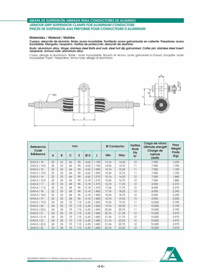
GRAPA DE SUSPENSIÓN ARMADA PARA CONDUCTORES DE ALUMINIOARMOUR GRIP SUSPENSION CLAMPS FOR ALUMINIUM CONDUCTORSPINCES DE SUSPENSION AGS PREFORME POUR CONDUCTEURS D'ALUMINIUM
•5-5•
INDUSTRIAS ARRUTI, S.A. SPAIN • Internet: http://www.arruti.com
Materiales / Material / MatièreCuerpo: aleación de aluminio. Brida: acero inoxidable. Tornillería: acero galvanizado en caliente. Pasadores: aceroinoxidable. Manguito: neopreno. Varillas de protección: aleación de aluminioBody: aluminium alloy. Hinge: stainless steel Bolts and nuts: steel hot dip galvanized. Cotter pin: stainless steel Insert:neoprene. Armour rods: aluminium alloy.Corps: alliage d’aluminium. Bride : acier inoxydable. Boulon et écrou: acier galvanisé à chaud. Goupille: acierinoxydable. Insert : Néoprène. Armor rods: alliage d’aluminium.
C
B
A
M16
L
E
ØD
22222222222222222222222424242424242424
33333333333333333333333535353535353535
9090909090909696969696
115115115115115115115115
4,624,624,624,624,625,185,185,185,185,185,186,356,356,356,356,356,356,356,35
1.1501.1501.2001.2001.2701.2701.3701.3701.4001.4001.5001.6501.6501.6501.6801.6801.6801.6801.680
13,7614,2614,7615,2615,7616,2616,7617,2617,7618.2618,7619,2619,7620,2620,7621,2621,7621,2622,76
14,2514,7515,2515,7516,2516,7517,2517,7518,2518,7519,2519,7520,2520,7521,2521,7522,2522,7523,25
10111111121212121212131111111212121212
7.5007.5007.5007.5007.5007.5008.5008.5008.5008.5008.500
10.00010.00010.00010.00010.00010.00010.00010.000
66666666666668686868687070707070707070
1,6901,7501,7501,7501,8801,8802,3702,3702,3902,3902,5503,7903,7903,7903,9703,9703,9703,9703,970
ReferenciaCode
Référence
mmCarga de roturaUltimate strength
Charge derupture(daN)
PesoWeightPoids(Kg)Min
VarillasRodsFilsNºMaxA B C E Ø D L
Ø Conductor
GAS-3 / 14GAS-3 / 14,5GAS-3 / 15GAS-3 / 15,5GAS-3 / 16GAS-3 / 16,5GAS-4 / 17GAS-4 / 17,5GAS-4 / 18GAS-4 / 18,5GAS-4 / 19GAS-5 / 19,5GAS-5 / 20GAS-5 / 20,5GAS-5 / 21GAS-5 / 21,5GAS-5 / 22GAS-5 / 22,5GAS-5 / 23

GRAPA DE SUSPENSIÓN ARMADA PARA CONDUCTORES DE ALUMINIOARMOUR GRIP SUSPENSION CLAMPS FOR ALUMINIUM CONDUCTORSPINCES DE SUSPENSION AGS PREFORME POUR CONDUCTEURS D'ALUMINIUM
•5-6•
INDUSTRIAS ARRUTI, S.A. SPAIN • Internet: http://www.arruti.com
Materiales / Material / MatièreCuerpo: aleación de aluminio. Brida: acero inoxidable. Tornillería: acero galvanizado en caliente. Pasadores: aceroinoxidable. Manguito: neopreno. Varillas de protección: aleación de aluminioBody: aluminium alloy. Hinge: stainless steel Bolts and nuts: steel hot dip galvanized. Cotter pin: stainless steel Insert:neoprene. Armour rods: aluminium alloy.Corps: alliage d’aluminium. Bride : acier inoxydable. Boulon et écrou: acier galvanisé à chaud. Goupille: acierinoxydable. Insert : Néoprène. Armor rods: alliage d’aluminium.
C
B
A
M16
L
E
ØD
Estas tablas contienen los tipos de fabricación normal. Bajo pedido se podrán fabricar grapas para otros diámetros.This table shows the most standard clamps; clamps for any other size are availabe under request.Cette table contient les pinces de fabricacition normale. On peut fabriquer pinces pour outre diamètres sur commande.
ReferenciaCode
Référence
mmCarga de roturaUltimate strength
Charge derupture(daN)
PesoWeightPoids(Kg)Min
VarillasRodsFilsNºMaxA B C E Ø D L
Ø Conductor
GAS-6 / 23,5GAS-6 / 24GAS-6 / 24,5GAS-6 / 25GAS-6 / 25,5GAS-7 / 26GAS-7 / 27GAS-7 / 28GAS-7 / 29GAS-7 / 30GAS-8 / 31GAS-8 / 32GAS-8 / 33GAS-8 / 34GAS-8 / 35GAS-8 / 36GAS-8 / 37
23,2623,7624,2624,7625,2625,7626,5127,5128,5129,5130,5131,5132,5133,5134,5135,5136,51
23,7524,2524,7525,2525,7526,5027,5028,5029,5030,5031,5032,5033,5034,5035,5036,5037,50
2424242424242424242424242424242424
3535353535353535353535353535353535
115115115115115140140140140140140140140140140140140
6,356,356,356,356,357,877,877,877,877,877,879,279,279,279,279,279,27
1.9301.9301.9301.9301.9302.0802.0802.0802.0802.0802.0802.0802.0802.0802.0802.0802.080
1213131313121212121311121212121313
12.00012.00012.00012.00012.00012.00012.00012.00012.00012.00012.00012.00012.00012.00012.00012.00012.000
7070707070808080808080808080808080
5,1005,3005,3005,3005,3006,9506,9506,9506,9507,3008,2508,7008,7008,7008,7009.1009,100

ENGANCHES DE CONTRAPESOSCOUNTERWEIGHT FITTINGS / ACCESOIRES POUR CONTREPOIDS
•5-7•
INDUSTRIAS ARRUTI, S.A. SPAIN • Internet: http://www.arruti.com
Utilización / Usage / UtilisationEste conjunto de herrajes sirve para poder colgar los contrapesos de la grapa de suspensión.This fitting set is used to hold down the counterweights below the suspension clamp.Ces accessoires sont utilisés pour pouvoir suspendre les contrepoids sur la pince de suspension.
Materiales / Material / MatièreCuerpo: acero galvanizado en caliente. Tornillería: acero galvanizado en caliente. Pasadores: acero inoxidable o latón.Body: steel hot dip galvanised. Bolt and nut: steel hot dip galvanized. Cotter pin: stainless steel or brass.Corps: acier galvanisé à chaud. Boulon et écrou: acier galvanisé à chaud. Goupille: acier inoxydable ou laiton.
B
A
B
A
M-1
6
25
34
34
25
M-1
6
A
M-1
6
25
34
B
Fig. 2Fig. 1
Fig. 3
ECP-1 1 GS-1 180 138 2,200ECP-2 1 GS-2 180 130 2,200ECP-3 2 GS-3 220 166 2,500ECP-4 2 GS-4 220 169 2,500ECP-5 2 GS-5 220 158 2,500ECP-4A 2 GS-4-AE 220 154 2,500ECP-5A 2 GS-5-AE 220 150 2,500ECP-6A 2 GS-6-AE 220 144 2,500ECP-1/2S 3 GAS-1, GAS-2 220 164 2,500ECP-3S 3 GAS-3 220 154 2,500ECP-4S 3 GAS-4 220 152 2,500ECP-5/6S 3 GAS-5, GAS-6 280 210 2,700ECP-7/8S 3 GAS-7, GAS-8 280 200 2,700
mmReferenciaCode
Référence
PesoWeightPoids(Kg)A B
Fig.GrapaClampPince

CONTRAPESOS CILINDRICOSCYLINDRICAL COUNTERWEIGHTS / CONTREPOIDS CYLINDRIQUE
•5-8•
INDUSTRIAS ARRUTI, S.A. SPAIN • Internet: http://www.arruti.com
Utilización / Usage / UtilisationLos contrapesos cilíndricos son utilizados para contrapesar las cadenas de suspensión. Estos elementos se cuelgande la grapa de suspensión mediante un enganche de contrapeso (mirar en este catálogo el modelo de enganchemás adecuado para la grapa a utilizar).Cylindrical counterweights are used to add weight to a suspension string. They are suspended below the suspensionclamp by a hold down system (select in this catalogue the more adequate type of hold down system for the clamp).Les contrepoids cylindriques sont utilisés pour contre - balancer les chaînes de suspension. Ces éléments sont pendusde la pince de suspension avec un crochet de contrepoids (regarder à ce catalogue le model de crochet plusvalable pour la pince a utiliser).
Materiales / Material / MatièreCuerpo: fundición de hierro galvanizada. Tornillo de ojo y tuerca: acero galvanizado en caliente. Pasadores: aceroinoxidable o latón.Body: iron casting hot dip galvanised. Eye bolt and nut: steel hot dip galvanized. Cotter pin: stainless steel or brass.Corps: Fonte galvanisée à chaud. Boulon et écrou: acier galvanisé à chaud. Goupille: acier inoxydable ou laiton.
CPC-5
CPC-10
Ø35
2550
50
190
A
B
M-16
Bajo pedido se podrán suministrar estos contrapesos con más peso.Counterweights with any other weight are available under request.Sur commandé on peut fournir ces contrepoids avec les poids souhaités.
ReferenciaCode
Référence
CáncamoEye Bolt
Ceillet Bolt
mm
A B
PesoWeightPoids(Kg)
Nº de ContrapesosCounterweight (No)
CPC-5(5 kg)
CPC-10(10 kg)
CPC-5 5 1 0 TC-16-160 210 160CPC-5 / 2 10 2 0 TC-16-160 210 160CPC-10 10 0 1 TC-16-160 210 160CPC-15 15 1 1 TC-16-160 210 160CPC-10 / 2 20 0 2 TC-16-250 300 250CPC-25 25 1 2 TC-16-250 300 250CPC-10 / 3 30 0 1 TC-16-250 300 250CPC-35 35 1 3 TC-16-250 300 250CPC-10 / 4 40 0 4 TC-16-250 300 250CPC-45 45 1 4 TC-16-340 390 340CPC-10 / 5 50 0 5 TC-16-340 390 340CPC-55 55 1 5 TC-16-340 390 340CPC-10 / 6 60 0 6 TC-16-340 390 340

CONTRAPESOS RECTANGULARESRECTANGULAR COUNTERWEIGHTS / CONTREPOIDS RECTANGULAIRE
•5-9•
INDUSTRIAS ARRUTI, S.A. SPAIN • Internet: http://www.arruti.com
Utilización / Usage / UtilisationLos contrapesos rectangulares son utilizados para contrapesar las cadenas de suspensión. Estos elementos se cuelgande la grapa de suspensión mediante un enganche de contrapeso (mirar en este catálogo el modelo de enganchemás adecuado para la grapa a utilizar). El incremento de peso es de 20 kg.Rectangular counterweights are used to add weight to a suspension string. They are suspended below the suspensionclamp by a hold down system (select in this catalogue the more adequate type of hold down system for the clamp).Weight increment: 20 kg.Les contrepoids rectangulaires sont utilisés pour contre - balancer les chaînes de suspension. Ces éléments sont pendusde la pince de suspension avec un crochet de contrepoids (regarder à ce catalogue le model de crochet plusvalable pour la pince a utiliser). L’accroissement de poids est de 20 kg.
Materiales / Material / MatièreCuerpo: fundición de hierro galvanizada. Tirante y tornillería: acero galvanizado en caliente. Pasadores: aceroinoxidable o latón.Body: iron casting hot dip galvanised. Extension link, bolt and nut: steel hot dip galvanized. Cotter pin: stainless steelor brass.Corps: Fonte de fer galvanisée à chaud. Rallonge, boulon et écrou: acier galvanisé à chaud. Goupille: acier inoxydableou laiton.
21
Ø17,5
45
15
38
400
200
A
Bajo pedido se podrán suministrar estos contrapesos con más peso.Counterweights with any other weight are available under request.Sur commandé on peut fournir ces contrepoids avec les poids souhaités.
Elementos (Nº)Elements (Nº)Pièces (Nbre)
Amm
PesoWeightPoids(Kg)
ReferenciaCode
Référence
Ref. tiranteExtension link
Rallonge
1 CPR-20 /1 TA-1 / 200 200 202 CPR-20 / 2 TA-1 / 200 200 403 CPR-20 / 3 TA-1 / 200 200 604 CPR-20 / 4 TA-1 / 300 300 805 CPR-20 / 5 TA-1 / 300 300 1006 CPR-20 / 6 TA-1 / 300 300 1207 CPR-20 / 7 TA-1 / 400 400 1408 CPR-20 / 8 TA-1 / 400 400 1609 CPR-20 / 9 TA-1 / 500 500 180
10 CPR-20 / 10 TA-1 / 500 500 20011 CPR-20 / 11 TA-1 / 600 600 22012 CPR-20 / 12 TA-1 / 600 600 24013 CPR-20 / 13 TA-1 / 600 600 26014 CPR-20 / 14 TA-1 / 700 700 28015 CPR-20 / 15 TA-1 / 700 700 300

CONTRAPESOS PARA LINEA DUPLEXCOUNTERWEIGHTS FOR TWIN BUNDLE / CONTREPOIDS POUR LIGNE DOUBLE
INDUSTRIAS ARRUTI, S.A. SPAIN • Internet: http://www.arruti.com
Utilización / Usage / UtilisationEste tipo de contrapesos rectangulares son utilizados para contrapesar las cadenas de suspensión provistas de dobleconductor. Estos elementos se cuelgan de la grapa de suspensión mediante un enganche de contrapeso (mirar eneste catálogo el modelo de enganche más adecuado para la grapa a utilizar). El incremento de peso es de 30 kg.This kind of rectangular counterweights are used to add weight to a suspension string for twin bundle. They aresuspended below the suspension clamp by a hold down system (select in this catalogue the more adequate typeof hold down system for the clamp). Weight increment: 30 kg.Ce type de contrepoids rectangulaires est utilisé pour contre - balancer les chaînes de suspension avec doubleconducteur. Ces éléments sont pendus de la pince de suspension avec un crochet de contrepoids (regarder à cecatalogue le model de crochet plus valable pour la pince a utiliser). L’accroissement de poids est de 30 kg.
Materiales / Material / MatièreCuerpo: fundición de hierro galvanizada. Tirante y tornillería: acero galvanizado en caliente. Pasadores: acero inoxidableo latón.Body: iron casting hot dip galvanised. Extension link, bolt and nut: steel hot dip galvanized. Cotter pin: stainless steelor brass.Corps: Fonte de fer galvanisée à chaud. Rallonge, boulon et écrou: acier galvanisé à chaud. Goupille: acier inoxydableou laiton.
Bajo pedido se podrán suministrar estos contrapesos con diferente distancia entre conductores y con más peso.Counterweights with any other conductor distance and weight are available under request.Sur commandé on peut fournir ces contrepoids avec une autre distance entre conducteurs et un poids plus grand.
•5-10•
A
15
400 260
52526
034
45
21 Ø17,5
Elementos (Nº)Elements (Nº)Pièces (Nbre)
Amm
PesoWeightPoids(Kg)
ReferenciaCode
Référence
Ref. tiranteExtension link
Rallonge
1 CPR-30 /1V TA-1 / 200 200 302 CPR-30 / 2V TA-1 / 200 200 603 CPR-30 / 3V TA-1 / 200 200 904 CPR-30 / 4V TA-1 / 300 300 1205 CPR-30 / 5V TA-1 / 300 300 1506 CPR-30 / 6V TA-1 / 300 300 1807 CPR-30 / 7V TA-1 / 400 400 2108 CPR-30 / 8V TA-1 / 400 400 2409 CPR-30 / 9V TA-1 / 500 500 270
10 CPR-30 / 10V TA-1 / 500 500 300

GRAPAS DE AMARRE PARA CONDUCTORES DE ALUMINIOSTRAIN CLAMPS FOR ALUMINIUM CONDUCTORSPINCES D'ANCRAGE POUR CONDUCTEURS D'ALUMINIUM
•5-11•
INDUSTRIAS ARRUTI, S.A. SPAIN • Internet: http://www.arruti.com
Utilización / Usage / UtilisationEstas grapas son utilizadas para amarrar conductores de aluminio, aleación de aluminio y aluminio-acero. A la horade la instalación, es importante respetar el par de apriete recomendado, que está estudiado para garantizar undeslizamiento superior al 95% de la carga de rotura del conductor y minimizar los esfuerzos de compresión sobre elconductor a unos límites aceptables.These clamps are used to fix aluminium, aluminium alloy and aluminium steel reinforced conductors. During installation,recommended torque must be respected, since in this way, a slipping force higher than 95% of conductor breakingstrength is guaranteed, and compression stresses on the conductor are minimised to acceptable values.Les pinces d’ancrage sont utilisées pour attacher conducteurs d’aluminium, alliage d’aluminium et aluminium – acier.Au moment de l’installation il est important de respecter le couple de serrage recommandé, qui a été étudié pourgarantir un glissement supérieur au 95% de la charge rupture du conducteur et minimiser les efforts de compressionsur le conducteur dans des limites acceptables.
Materiales / Material / MatièreCuerpo: aleación de aluminio. Tornillos y bulones: acero galvanizado en caliente. Pasadores: acero inoxidable o latón.Body: aluminium alloy. Bolt, nut and clevis pin: steel hot dip galvanized. Cotter pin: stainless steel or brass.Corps: alliage d’aluminium. Boulon, écrou et axe: acier galvanisé à chaud. Goupille: acier inoxydable ou laiton.
Estas grapas pueden suministrarse con estribos de acero inoxidable. Para ello añadir el sufijo I a la referencia. Por ejemplo: GA-2-I.These clamps may be supplied with stainless steel U-Bolts under request. Letter I must be added to code. For instance: GA-2-I.Ces pinces peuvent être fournies avec étriers en acier inoxydable. Ajouter la lettre I sélectionnée. Par exemple: GA-2-I.
A
D
B
C
A
DL
GA-1-P 1 6 10 19 80 M-10 16 120 2 2,5 2.500 0,400GA-1 1 6 10 19 125 M-12 16 155 2 3,5 4.000 0,700GA-1T 2 6 10 19 125 M-12 M-16 155 2 3,5 4.000 0,700GA-2 1 10 16 20 145 M-12 16 245 3 4,5 6.500 1,300GA-2T 2 10 16 20 145 M-12 M-16 245 3 4,5 6.500 1,300GA-2-L 1 9 18 19 203 M-12 16 280 3 4,5 6.500 1,400GA-2-LT 2 9 18 19 203 M-12 M-16 280 3 4,5 6.500 1,400GA-3 1 16 20 22 194 M-12 16 345 4 5 8.500 2,000GA-3T 2 16 20 22 194 M-12 M-16 345 4 5 8.500 2,000GA-4T 2 20 31 39 245 M-14 M-16 460 5 8 13.500 4,300
ReferenciaCode
Référence
mmCarga de roturaUltimate strength
Charge de rupture(daN)
PesoWeightPoids(Kg)
Fig.
A B D NºMax. LMin. C
EstribosU-boltsEtriers
Ø ConductorConductor Ø
Ø Conducteur
Par de aprieteTightening Torque
Couple de Serrage(kg.m)
Fig. 1
Fig. 2

CONTRAPESOS PARA BUCLESJUMPER COUNTERWEIGHTS / CONTREPOIDS POUR CHAINE D'ANCRAGE
INDUSTRIAS ARRUTI, S.A. SPAIN • Internet: http://www.arruti.com
Utilización / Usage / UtilisationLos contrapesos de bucle son utilizados para contrapesar las cadenas de amarre y los puentes flojos. Estos elementosse montan directamente en el conductor.Jumper counterweights are used to add weight to the tension string and jumpers. These elements are attached directlyto the conductor.Les contrepoids pour chaîne d’ancrage sont employés pour contre – balancer les chaînes d’ancrage et les bretelles.Le montage de ces accessoires est fait directement sur le conducteur.
Materiales / Material / MatièreCuerpo: fundición de hierro galvanizada. Tornillería: acero galvanizado en caliente.Body: iron casting hot dip galvanised. Bolt and nut: steel hot dip galvanized.Corps: Fonte de fer galvanisée à chaud. Boulon et écrou: acier galvanisé à chaud.
•5-12•
M-12
A
B
C
CPB – 7 14 22 160 84 90 3 7,000CPB-10 / 1 14 22 160 110 90 3 10,000CPB – 10 22 30 160 110 90 3 10,000
mmReferenciaCode
Référence
Par de aprieteTightening Torque
Couple de Serrage(kg.m)
PesoWeightPoids(kg)Mín. AMáx. B C
Ø ConductorConductor Ø
Ø Conducteur

ACCESORIOS PARA CABLE DE TIERRA
ACCESSOIRES POUR CABLE DE GARDE
ACCESSORIES FOR EARTHWIRE
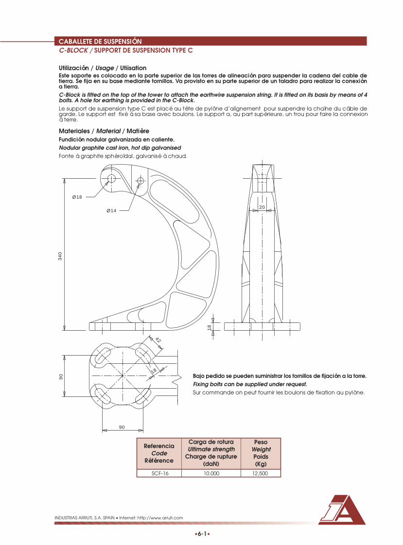
CABALLETE DE SUSPENSIÓNC-BLOCK / SUPPORT DE SUSPENSION TYPE C
INDUSTRIAS ARRUTI, S.A. SPAIN • Internet: http://www.arruti.com
•6-1•
Utilización / Usage / UtiisationEste soporte es colocado en la parte superior de las torres de alineación para suspender la cadena del cable detierra. Se fija en su base mediante tornillos. Va provisto en su parte superior de un taladro para realizar la conexióna tierra.C-Block is fitted on the top of the tower to attach the earthwire suspension string. It is fitted on its basis by means of 4bolts. A hole for earthing is provided in the C-Block.Le support de suspension type C est placé au tète de pylône d’alignement pour suspendre la chaîne du câble degarde. Le support est fixé à sa base avec boulons. Le support a, au part supérieure, un trou pour faire la connexioná terre.
Materiales / Material / MatièreFundición nodular galvanizada en caliente.Nodular graphite cast iron, hot dip galvanisedFonte à graphite sphéroïdal, galvanisé à chaud.
Bajo pedido se pueden suministrar los tornillos de fijación a la torre.Fixing bolts can be supplied under request.Sur commande on peut fournir les boulons de fixation au pylône.
1820
340
Ø14
42
18
90
Ø18
90
SCF-16 10.000 12,500
ReferenciaCode
Référence
Carga de roturaUltimate strength
Charge de rupture(daN)
PesoWeightPoids(Kg)

GRAPAS DE SUSPENSIÓN PARA CABLES DE ACEROSUSPENSION CLAMPS FOR STEEL CABLES / PINCES DE SUSPENSION POUR CABLE D'ACIER
•6-2•
INDUSTRIAS ARRUTI, S.A. SPAIN • Internet: http://www.arruti.com
Utilización / Usage / UtilisationEstas grapas son utilizadas para suspender cables de tierra de acero galvanizado y acero recubierto de aluminio.También son adecuados para cables de cobre. A la hora de la instalación, es importante respetar el par de aprieterecomendado, que está estudiado para garantizar un deslizamiento superior al 20% de la carga de rotura del cabley minimizar los esfuerzos de compresión sobre el cable a unos límites aceptables.These clamps are used for the suspension of galvanized steel and aluminium covered steel earthwires. They are alsorecommended for copper conductors. During installation, recommended torque must be respected, since in this way,a slipping force higher than 20% of cable breaking strength is guaranteed, and compression stresses on the cableare minimised to acceptable values.Ces pinces sont employées pour suspendre des câbles de garde d’acier galvanisé et acier recouvert d’aluminium.Aussi on l’emploi pour câble de cuivre. Quand il arrive le moment de l’installation, il est important respecter le couplede serrage recommandé, qui a été étudié pour garantir un glissement supérieur au 20% de la charge rupture duconducteur et minimiser les efforts de compression sur le conducteur dans des limites acceptables.
Materiales / Material / MatièreCuerpo: acero forjado galvanizada en caliente. Tornillería: acero galvanizado en caliente. Pasador: acero inoxidable.Body: forged steel, hot dip galvanised. Bolt, nut and U-bolts: steel hot dip galvanized. Cotter pin: stainless steel.Corps: acier forge, galvanisé à chaud. Boulon, écrou et étriers: acier galvanisé à chaud. Goupille: acier inoxydable.
D
C
L
B
A
ReferenciaCode
Référence
mmCarga de roturaUltimate strength
Charge derupture(daN)
PesoWeightPoids(Kg)
Max. A B C D L NºMin.
EstribosU-boltsEtriers
Par de aprieteTightening Torque
Couple de Serrage(kg.m)
GS-AC-12 5 12 16 45 M-12 M-16 170 2 5 8.000 1,500
Ø ConductorConductor Ø
Ø Conducteur
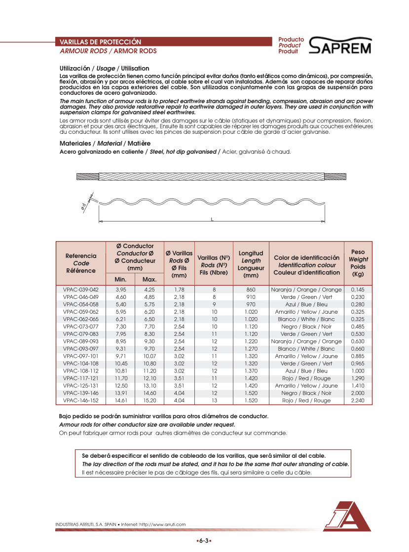
VARILLAS DE PROTECCIÓNARMOUR RODS / ARMOR RODS
•6-3•
INDUSTRIAS ARRUTI, S.A. SPAIN • Internet: http://www.arruti.com
Utilización / Usage / UtilisationLas varillas de protección tienen como función principal evitar daños (tanto estáticos como dinámicos), por compresión,flexión, abrasión y por arcos eléctricos, al cable sobre el cual van instaladas. Además son capaces de reparar dañosproducidos en las capas exteriores del cable. Son utilizadas conjuntamente con las grapas de suspensión paraconductores de acero galvanizado.The main function of armour rods is to protect earthwire strands against bending, compression, abrasion and arc powerdamages. They also provide restorative repair to earthwire damaged in outer layers. They are used in conjunction withsuspension clamps for galvanised steel earthwires.Les armor rods sont utilisés pour éviter des damages sur le câble (statiques et dynamiques) pour compression, flexion,abrasion et pour des arcs électriques,. Ensuite ils sont capables de réparer les damages produits aux couches extérieuresdu conducteur. Ils sont utilises avec les pinces de suspension pour câble de garde d’acier galvanise.
Materiales / Material / MatièreAcero galvanizado en caliente / Steel, hot dip galvanised / Acier, galvanisé à chaud.
Bajo pedido se podrán suministrar varillas para otros diámetros de conductor.Armour rods for other conductor size are available under request.On peut fabriquer armor rods pour autres diamètres de conducteur sur commande.
Se deberá especificar el sentido de cableado de las varillas, que será similar al del cable.The lay direction of the rods must be stated, and it has to be the same that outer stranding of cable.Il est nécessaire préciser le pas de câblage des fils, qui sera similaire a celle du câble.
VPAC-039-042 3,95 4,25 1,78 8 860 Naranja / Orange / Orange 0,145VPAC-046-049 4,60 4,85 2,18 8 910 Verde / Green / Vert 0,230VPAC-054-058 5,40 5,75 2,18 9 970 Azul / Blue / Bleu 0,280VPAC-059-062 5,95 6,20 2,18 10 1.020 Amarillo / Yellow / Jaune 0,325VPAC-062-065 6,21 6,50 2,18 10 1.020 Blanco / White / Blanc 0,325VPAC-073-077 7,30 7,70 2,54 10 1.120 Negro / Black / Noir 0,485VPAC-079-083 7,95 8,30 2,54 11 1.120 Verde / Green / Vert 0,530VPAC-089-093 8,95 9,30 2,54 12 1.220 Naranja / Orange / Orange 0,630VPAC-093-097 9,31 9,70 2,54 12 1.270 Blanco / White / Blanc 0,660VPAC-097-101 9,71 10,07 3,02 11 1.320 Amarillo / Yellow / Jaune 0,885VPAC-104-108 10,45 10,80 3,02 12 1.320 Verde / Green / Vert 0,965VPAC-108-112 10,81 11,20 3,02 12 1.370 Azul / Blue / Bleu 1,000VPAC-117-121 11,70 12,10 3,51 11 1.420 Rojo / Red / Rouge 1,290VPAC-125-131 12,50 13,10 3,51 12 1.420 Amarillo / Yellow / Jaune 1,410VPAC-139-146 13,91 14,60 4,04 12 1.520 Negro / Black / Noir 2,000VPAC-146-152 14,61 15,20 4,04 13 1.520 Rojo / Red / Rouge 2,240
ReferenciaCode
Référence
Color de identificaciónIdentification colour
Couleur d'identification
PesoWeightPoids(Kg)
Min. Max.
Varillas (Nº)Rods (Nº)Fils (Nbre)
LongitudLength
Longueur(mm)
Ø VarillasRods ØØ Fils(mm)
Ø ConductorConductor Ø
Ø Conducteur(mm)
L
ød
ProductoProductProduit

VARILLAS DE PROTECCIÓNARMOUR RODS / ARMOR RODS
•6-4•
INDUSTRIAS ARRUTI, S.A. SPAIN • Internet: http://www.arruti.com
Utilización / Usage / UtilisationLas varillas de protección tienen como función principal evitar daños (tanto estáticos como dinámicos), por compresión,flexión, abrasión y por arcos eléctricos, al cable sobre el cual van instaladas. Además son capaces de reparardaños producidos en las capas exteriores del cable. Son utilizadas conjuntamente con las grapas de suspensiónpara conductores de acero recubierto de aluminio.The main function of armour rods is to protect earthwire strands against bending, compression, abrasion and arcpower damages. They also provide restorative repair to earthwire damaged in outer layers. They are used in conjunctionwith suspension clamps for aluminium clad steel earthwires.Les armor rods sont utilisés pour éviter des damages sur le câble (statiques et dynamiques) pour compression, flexion,abrasion et pour des arcs électriques,. Ensuite ils sont capables de réparer les damages produits aux couchesextérieures du conducteur. Ils sont utilises avec les pinces de suspension pour câble d’acier recouvert d’aluminium.
Materiales / Material / MatièreAcero recubierto de aluminio / Aluminium clad steel / Acier recouvert d’aluminium.
Bajo pedido se podrán suministrar varillas para otros diámetros de conductor.Armour rods for other conductor size are available under request.On peut fabriquer armor rods pour autres diamètres de conducteur sur commande.
Se deberá especificar el sentido de cableado de las varillas, que será similar al del cable.The lay direction of the rods must be stated, and it has to be the same that outer stranding of cable.Il est nécessaire préciser le pas de câblage des fils, qui sera similaire a celle du câble.
VPAW-080-084 8,00 8,44 2,91 10 1.220 Verde / Green / Vert 0,585VPAW-O84-089 8,45 8,94 2,91 10 1.270 Azul / Blue / Bleu 0,610VPAW-O89-094 8,95 9,44 3,26 10 1.270 Rojo / Red / Rouge 0,770VPAW-094-099 9,45 9,94 3,26 10 1.270 Verde / Green / Vert 0,770VPAW-099-103 9,95 10,34 3,26 11 1.320 Amarillo / Yellow / Jaune 0,880VPAW-103-108 10,35 10,80 3,26 11 1.370 Rojo / Red / Rouge 0,920VPAW-108-114 10,81 11,44 3,26 12 1.420 Azul / Blue / Bleu 1,050VPAW-114-121 11,45 12,10 3,66 11 1.420 Negro / Black / Noir 1,200VPAW-121-128 12,11 12,80 3,66 12 1.420 Verde / Green / Vert 1,310VPAW-128-137 12,81 13,70 4,12 11 1.470 Amarillo / Yellow / Jaune 1,570VPAW-137-146 13,71 14,60 4,12 12 1.470 Rojo / Red / Rouge 1,700VPAW-146-155 14,61 15,50 4,62 12 1.520 Azul / Blue / Bleu 2,220VPAW-155-165 15,51 16,50 4,62 12 1.570 Verde / Green / Vert 2,300
ReferenciaCode
Référence
Color de identificaciónIdentification colour
Couleur d'identification
PesoWeightPoids(Kg)
Min. Max.
Varillas (Nº)Rods (Nº)Fils (Nbre)
LongitudLength
Longueur(mm)
Ø VarillasRods ØØ Fils(mm)
Ø ConductorConductor Ø
Ø Conducteur(mm)
L
ød
ProductoProductProduit

GRAPA DE SUSPENSIÓN ARMADA PARA CABLES DE TIERRA DE ACERO GALVANIZADOARMOUR GRIP SUSPENSION CLAMPS FOR GALVANISED STEEL EARTHWIREPINCES DE SUSPENSION AGS PREFORME POUR CABLE DE GARDE EN ACIER GALVANISE
•6-5•
INDUSTRIAS ARRUTI, S.A. SPAIN • Internet: http://www.arruti.com
Utilización / Usage / UtilisationEste tipo de grapa de suspensión está diseñada para ofrecer una protección extra al conductor. Las varillas deprotección suministradas con la grapa (fabricadas de material compatible con el cable), tienen la propiedad deevitar los daños en el cable (tanto estáticos como dinámicos), por compresión, flexión, abrasión y por arcos eléctricos.En el interior de la grapa se coloca un manguito de neopreno que minimiza los esfuerzos en el punto de enclavamiento.Además, el conjunto tiene propiedades amortiguadoras de las vibraciones eólicas.This kind of clamp is intended to provide extra protection to the conductor. The armour rods supplied with the AGSsystem (manufactured with material compatible with the cable), protect conductor/strands against bending,compression, abrasion and arc power damages. The conductor is also protected in the point of clamping by aneoprene insert that minimise stresses at that point. The AGS system, provide to the suspension string damping propertiesagainst aeolian vibration.Ce type de pince est dessiné pour offrir une protection extra au câble de garde. Les armor rods, fournis avec lespinces (fabriqués avec du matériel compatible avec le câble), ont la proprette d’éviter des damages sur le câble(statiques et dynamiques) pour compression, flexion, abrasion et pour des arcs électriques. Dans l’intérieur de la pinceon place une pièce de Néoprène qui minimise les efforts au point d’enclavement. La pince a des proprettes pourl’amortissement des vibrations éoliennes.
Materiales / Material / MatièreCuerpo: aleación de aluminio. Brida: acero inoxidable. Tornillería: acero galvanizado en caliente. Pasador: aceroinoxidable. Manguito: neopreno. Varillas de protección: acero galvanizado.Body: aluminium alloy. Hinge: stainless steel Bolts and nuts: steel hot dip galvanized. Cotter pin: stainless steel. Insert:neoprene. Armour rods: galvanised steel.Corps: alliage d’aluminium. Bride : acier inoxydable. Boulon et écrou: acier galvanisé à chaud. Goupille: acierinoxydable. Insert: Néoprène. Armor rods: acier galvanise.
Bajo pedido se podrán fabricar grapas para otras medidas de cable.Clamps for other cable size under request.Sur commande on peut fabriquer pinces pour autres dimensions de câble.
C
B
A
M16
L
E
ØD
1,2701,3601,4851,6001,6001,7701,890
GAS-1 / 9-ACGAS-1 / 9,5-ACGAS-1 / 1 0-ACGAS-1 / 10,5-ACGAS-1 / 11-ACGAS-1 / 11,5-ACGAS-1 / 12-AC
ReferenciaCode
Référence
mmCarga de roturaUltimate strength
Charge derupture(daN)
PesoWeightPoids(Kg)B E LMin. Max. C Ø D
Ø ConductorConductor Ø
Ø Conducteur
VarillasRodsFilsNºA
8,709,269,76
10,2610,7611,2611,76
9,259,75
10,2510,7511,2511,7512,25
22222222222222
30303030303030
56565656565656
65656565656565
3,023,023,023,023,023,513,51
1.1001.2501.3201.3701.3701.4201.420
10101112121011
5.0005.0005.0005.0005.0005.0005.000

GRAPA DE SUSPENSION ARMADA PARA CABLES DE TIERRA DE ACERO RECUBIERTO DE ALUMINIOARMOUR GRIP SUSPENSION CLAMPS FOR ALUMINIUM COVERED STEEL EARTHWIREPINCES DE SUSPENSION AGS PREFORME POUR CABLE DE GARDE RECOUVERT D'ALUMINIUM
•6-6•
INDUSTRIAS ARRUTI, S.A. SPAIN • Internet: http://www.arruti.com
Utilización / Usage / UtilisationEste tipo de grapa de suspensión está diseñada para ofrecer una protección extra al conductor. Las varillas deprotección suministradas con la grapa (fabricadas de material compatible con el cable), tienen la propiedad deevitar los daños en el cable (tanto estáticos como dinámicos), por compresión, flexión, abrasión y por arcos eléctricos.En el interior de la grapa se coloca un manguito de neopreno que minimiza los esfuerzos en el punto de enclavamiento.Además, el conjunto tiene propiedades amortiguadoras de las vibraciones eólicas.This kind of clamp is intended to provide extra protection to the conductor. The armour rods supplied with the AGSsystem (manufactured with material compatible with the cable), protect conductor/strands against bending,compression, abrasion and arc power damages. The conductor is also protected in the point of clamping by aneoprene insert that minimise stresses at that point. The AGS system, provide to the suspension string damping propertiesagainst aeolian vibration.Ce type de pince est dessiné pour offrir une protection extra au câble de garde. Les armor rods, fournis avec lespinces (fabriqués avec du matériel compatible avec le câble), ont la proprette d’éviter des damages sur le câble(statiques et dynamiques) pour compression, flexion, abrasion et pour des arcs électriques. Dans l’intérieur de la pinceon place une pièce de Néoprène qui minimise les efforts au point d’enclavement. La pince a des proprettes pourl’amortissement des vibrations éoliennes.
Materiales / Material / MatièreCuerpo: aleación de aluminio. Brida: acero inoxidable. Tornillería: acero galvanizado en caliente. Pasador: aceroinoxidable. Manguito: neopreno. Varillas de protección: acero recubierto de aluminio.Body: aluminium alloy. Hinge: stainless steel Bolts and nuts: steel hot dip galvanized. Cotter pin: stainless steel. Insert:neoprene. Armour rods: aluminium covered steel.Corps: alliage d’aluminium. Bride : acier inoxydable. Boulon et écrou: acier galvanisé à chaud. Goupille: acierinoxydable. Insert: Néoprène. Armor rods: acier recouvert d'aluminium.
Bajo pedido se podrán fabricar grapas para otras medidas de cable.Clamps for other cable size under request.Sur commande on peut fabriquer pinces pour autres dimensions de câble.
C
B
A
M16
L
E
ØD
1,2001,2001,3701,3701,6501,6501,800
GAS-1 / 9-AWGAS-1 / 9,5-AWGAS-1 / 1 0-AWGAS-1 / 10,5-AWGAS-1 / 11-AWGAS-1 / 11,5-AWGAS-1 / 12-AW
ReferenciaCode
Référence
mmCarga de roturaUltimate strength
Charge derupture(daN)
PesoWeightPoids(Kg)B E LMin. Max. C Ø D
Ø ConductorConductor Ø
Ø Conducteur
VarillasRodsFilsNºA
8,709,269,76
10,2610,7611,2611,76
9,259,75
10,2510,7511,2511,7512,25
22222222222222
30303030303030
56565656565656
65656565656565
3,263,263,263,263,263,263,66
1.1001.1001.2701.2701.4201.4201.420
99
1010121211
5.0005.0005.0005.0005.0005.0005.000
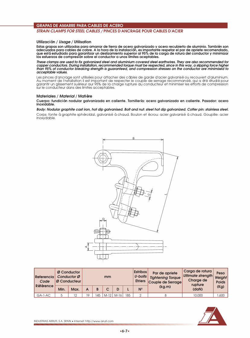
GRAPAS DE AMARRE PARA CABLES DE ACEROSTRAIN CLAMPS FOR STEEL CABLES / PINCES D'ANCRAGE POUR CABLES D'ACIER
•6-7•
INDUSTRIAS ARRUTI, S.A. SPAIN • Internet: http://www.arruti.com
Utilización / Usage / UtilisationEstas grapas son utilizadas para amarrar de tierra de acero galvanizado y acero recubierto de aluminio. También sonadecuados para cables de cobre. A la hora de la instalación, es importante respetar el par de apriete recomendado,que está estudiado para garantizar un deslizamiento superior al 95% de la carga de rotura del conductor y minimizarlos esfuerzos de compresión sobre el conductor a unos límites aceptables.These clamps are used to fix galvanized steel and aluminium covered steel earthwires. They are also recommended forcopper conductors. During installation, recommended torque must be respected, since in this way, a slipping force higherthan 95% of conductor breaking strength is guaranteed, and compression stresses on the conductor are minimised toacceptable values.Les pinces d'ancrage sont utilisées pour attacher des câbles de garde d'acier galvanisé ou recouvert d'aluminium.Au moment de I'nstallation il est important de respecter le couple de serrage recommandé, qui a été étudié pourgarantir un glissement suérieur aur 95% de la charge rupture du conducteur et minimiser les efforts de compressionsur le conducteur dans des limites acceptables.
Materiales / Material / MatièreCuerpo: fundición nodular galvanizada en caliente. Tornillería: acero galvanizado en caliente. Pasador: aceroinoxidable.Body: Nodular graphite cast iron, hot dip galvanised. Bolt and nut: steel hot dip galvanized. Cotter pin: stainless steel.Corps: fonte à graphite sphéroïdal, galvanisé à chaud. Boulon et écrou: acier galvanisé à chaud. Goupille: acierinoxydable.
LC
B
A
D
ReferenciaCode
Référence
mmCarga de roturaUltimate strength
Charge derupture(daN)
PesoWeightPoids(Kg)
Max. A B C D L NºMin.
EstribosU-boltsEtriers
Par de aprieteTightening Torque
Couple de Serrage(kg.m)
GA-1-AC 5 12 19 145 M-12 M-16 185 2 8 10.000 1,600
Ø ConductorConductor Ø
Ø Conducteur

GRAPAS DE COMPRESION PARA CABLES DE ACEROCOMPRESSION CLAMPS FOR STEEL CABLES / MANCHON D'ANCRAGE POUR CABLES D'ACIER
•6-8•
INDUSTRIAS ARRUTI, S.A. SPAIN • Internet: http://www.arruti.com
Utilización / Usage / UtilisationEstas grapas son utilizadas para el amarre de cables de tierra de acero galvanizado y acero recubierto de aluminio.La fijación del cable se consigue mediante compresión con una matriz hexagonal del tamaño adecuado (mirartabla). Es importante utilizar la matriz adecuada y respetar las zonas de compresión señaladas en la grapa, paragarantizar el correcto funcionamiento del conjunto.These clamps are used to fix galvanized steel and aluminium covered steel earthwires. Cable fixation is achieved bycompression with a hexagon die of the right size. It is very important to use the adequate die for the clamp and respectthe compression areas marked on the clamp, for assuring perfect performance of the system.Les pinces d’ancrage sont utilisées pour attacher des câbles de garde d’acier galvanisé ou recouvert d’aluminium.La fixation du câble est obtenue vers la compression d’une matrice hexagonale de la mesure appropriée (regardertable). Il est important utiliser la matrice appropriée et respecter les zones de compression marques dans la pince,pour garantir la fonctionnement correcte du conjoint.
Materiales / Material / MatièreAcero inoxidable forjado en caliente.Forged stainless steel.Acier inoxydable forge.
35120
28
C20
16 AØ
B
L
EC
ReferenciaCode
mmPeso
WeightPoids(Kg)CA LB
GAC-6 5,75 – 6,24 13 6,50 95 250 11 0,800GAC-6,5 6,25 – 6,74 13 7,00 95 250 11 0,800GAC-7 6,75 – 7,24 16 7,50 95 250 13,5 0,850GAC-7,5 7,25 – 7,74 16 8,00 95 250 13,5 0,850GAC-8 7,75 – 8,24 16 8,50 95 250 13,5 0,850GAC-8,5 8,25 – 8,74 19 9,00 140 295 16 0,950GAC-9 8,75 – 9,24 19 9,50 140 295 16 0,950GAC-9,5 9,25 – 9,74 22,5 10,00 140 295 19 1,050GAC-10 9,75 – 10,24 22,5 10,50 140 295 19 1,050GAC-10,5 10,25 – 10,74 22,5 11,00 140 295 19 1,050GAC-11 10,75 – 11,24 22,5 11,50 140 295 19 1,050GAC-11,5 11,25 – 11,74 26 12,00 140 295 22 1,100GAC-12 11,75 – 12,24 26 12,50 140 295 22 1,100
mm
Ø CableCable ØØ Câble
MatrizDie
Matrice
EC (mm)
Bajo pedido se podrán fabricar grapas para otras medidas de cable.Clamps for other cable size under request.Sur commande on peut fabriquer pinces pour autres dimensions de câble.

EMPALMES DE COMPRESION PARA CABLES DE ACEROMIDSPAN COMPRESSION JOINTS FOR STEEL CABLES / MANCHON DE JONCTION POUR CABLES D'ACIER
•6-9•
INDUSTRIAS ARRUTI, S.A. SPAIN • Internet: http://www.arruti.com
Utilización / Usage / UtilisationEstos empalmes se utilizan para empalmar cables de tierra de acero galvanizado y acero recubierto de aluminio,garantizando el 100% de la carga de rotura del cable. La fijación del cable se consigue mediante compresión conuna matriz hexagonal del tamaño adecuado (mirar tabla). Es importante utilizar la matriz adecuada y respetar laszonas de compresión señaladas en la grapa, para garantizar el correcto funcionamiento del conjunto.These joints are intended to joint galvanized steel and aluminium covered steel earthwires. Cable fixation is achieved bycompression with a hexagon die of the right size. It is very important to use the adequate die for the clamp and respectthe compression areas marked on the clamp, for assuring perfect performance of the system.Les manchons sont employés pour la jonction des câbles de garde d’acier galvanisé et acier recouvert d’aluminium,et garantie le 100% de la charge rupture du câble. La fixation du câble est obtenue vers la compression d’une matricehexagonale de la mesure appropriée (regarder table). Il est important utiliser la matrice appropriée et respecter leszones de compression marques dans la pince, pour garantir la fonctionnement correcte du conjoint.
Materiales / Material / MatièreAcero inoxidable.Stainless steel.Acier inoxydable.
L A
EC
ØB
Bajo pedido se podrán fabricar empalmes para otras medidas de cable.Joints for other cable size under request.Sur commande on peut fabriquer manchons de jonction pour autres dimensions de câble.
ReferenciaCode
Référence
mmPeso
WeightPoids(Kg)A LB
ECAC-6 5,75 – 6,24 13 6,50 200 11 0,150ECAC-6,5 6,25 – 6,74 13 7,00 200 11 0,150ECAC-7 6,75 – 7,24 16 7,50 225 13,5 0,250ECAC-7,5 7,25 – 7,74 16 8,00 225 13,5 0,250ECAC-8 7,75 – 8,24 16 8,50 225 13,5 0,250ECAC-8,5 8,25 – 8,74 19 9,00 245 16 0,400ECAC-9 8,75 – 9,24 19 9,50 245 16 0,400ECAC-9,5 9,25 – 9,74 22,5 10,00 265 19 0,650ECAC-10 9,75 – 10,24 22,5 10,50 265 19 0,650ECAC-10,5 10,25 – 10,74 22,5 11,00 265 19 0,650ECAC-11 10,75 – 11,24 22,5 11,50 265 19 0,650ECAC-11,5 11,25 – 11,74 26 12,00 275 22 0,900ECAC-12 11,75 – 12,24 26 12,50 275 22 0,900
mm
Ø CableCable ØØ Câble
MatrizDie
Matrice
EC (mm)

GUARDACABOSTHIMBLE / COSSE COEUR
•6-10•
INDUSTRIAS ARRUTI, S.A. SPAIN • Internet: http://www.arruti.com
Utilización / Usage / UtilisationLos guardacabos se utilizan para proteger las retenciones preformadas, debido a que su superficie curva y lisa repartelos esfuerzos mecánicos en la retención.Thimbles are use in conjunction with preformed dead ends, providing a smooth internal contour and avoiding stressconcentrations.Les cosses cœur sont employés pour protéger les ancrages spirales, étant donné que sa superficie courbe et platerepart les efforts mécaniques dans l’ancrage spiral.
Materiales / Material / MatièreCuerpo: fundición nodular galvanizada en caliente. Tornillería: acero galvanizado en caliente. Pasador: latón ó aceroinoxidable.Body: Nodular graphite cast iron, hot dip galvanised. Bolt and nut: steel hot dip galvanized. Cotter pin: bras or stainless steel.Corps: fonte à graphite sphéroïdal, galvanisé à chaud. Boulon et écrou: acier galvanisé à chaud. Goupille: laiton ouacier inoxydable.
58
22
M-1
6
48
100
Materiales / Material / MatièreAcero galvanizado en caliente. / Steel hot dip galvanised. / Acier galvanisé à chaud.
A
L
B
C
G-16 12.500 0,800
ReferenciaCode
Référence
Carga de roturaUltimate strength
Charge de rupture(daN)
PesoWeightPoids(Kg)
ReferenciaCode
Référence
mmPeso
WeightPoids(Kg)B CA
GC 15 25 52 102 0,125GC-1 12 16 30 67 0,050
L

RETENCIONES PREFORMADAS PARA CABLES DE TIERRAPREFORMED DEAD END FOR EARTHWIRESANCRAGES SPIRALES POUR CABLES DE GARDE
•6-11•
INDUSTRIAS ARRUTI, S.A. SPAIN • Internet: http://www.arruti.com
Utilización / Usage / UtilisationLas retenciones preformadas tienen como función amarrar los cables de tierra al apoyo. Están fabricadas con varillashelicoidales del mismo material que el cable para el cual va destinado y su principal ventaja es la sencillez demontaje; dicho montaje se efectuará con un guardacabos adecuado que proteja el lazo de la retención. Estosaccesorios garantizan una carga de rotura no inferior al 95% de la carga nominal del cable.Preformed dead ends are intended to hold earthwires to the tower. These products are manufactured with helical rodsmade of material compatible with the cable to which they are installed, and the main advantage of its use is the fastand easy application. Preformed dead ends must be used in conjunction with an adequate thimble for protection ofthe loop. Once the accessory is installed a slipping force higher than 95% of conductor breaking strength is guaranteed.Les ancrages spiraux sont employés pour l’ancrage des câbles de garde au pylône. Elles sont fabriquées avec desfils hélicoïdaux du même matériel que celle du câble pour lequel elles sont destinées et sa principale avantage estla facilité du montage; cet montage sera réalisé avec un cosse cœur approprie pour la protection du nœud de laspiral. Ces accessoires garantissent une charge rupture pas inférieur au 95% du charge nominal du câble.
Materiales / Material / MatièreAcero recubierto de aluminio. / Aluminium clad steel. / Acier recouvert d’aluminium.
L
Ød
Ø D
Bajo pedido se podrán suministrar retenciones para otros diámetros de conductor.Dead ends for other conductor size are available under request.On peut fabriquer ancrages pour autres diamètres de conducteur sur commande.
Se deberá especificar el sentido de cableado de la retención, que será similar al del cable.The lay direction of the dead ends must be stated, and it has to be the same that outer stranding of cable.Il est nécessaire préciser le pas de câblage des ancrages, qui sera similaire a celle du câble.
RAAW-074-078 7,40 7,80 2,59 680 5 50 Negro / Black / Noir 4.500RAAW-085-089 8,51 8,94 2,91 780 5 60 Azul / Blue / Bleu 5.500RAAW-089-093 8,95 9,30 2,59 780 6 60 Naranja / Orange / Orange 7.500RAAW-093-097 9,31 9,70 2,59 780 6 60 Blanco / White / Blanc 7.500RAAW-097-101 9,71 10,07 3,26 800 5 60 Verde / Green / Vert 6.500RAAW-108-112 10,81 11,20 3,26 870 6 60 Azul / Blue / Bleu 8.250RAAW-118-125 11,80 12,50 3,66 940 5 60 Negro / Black / Noir 10.000
ReferenciaCode
Référence
Color de identificaciónIdentification colour
Couleur d'identification
Carga de roturaUltimate strength
Charge de rupture(daN)
Min. Max.
Varillas (Nº)Rods (Nº)Fils (Nbre)
LongitudLength
Longueur(mm)
Ø VarillasRods ØØ Fils(mm)
Ø CableCable ØØ Câble
(mm)Ø D
(mm)
ProductoProductProduit
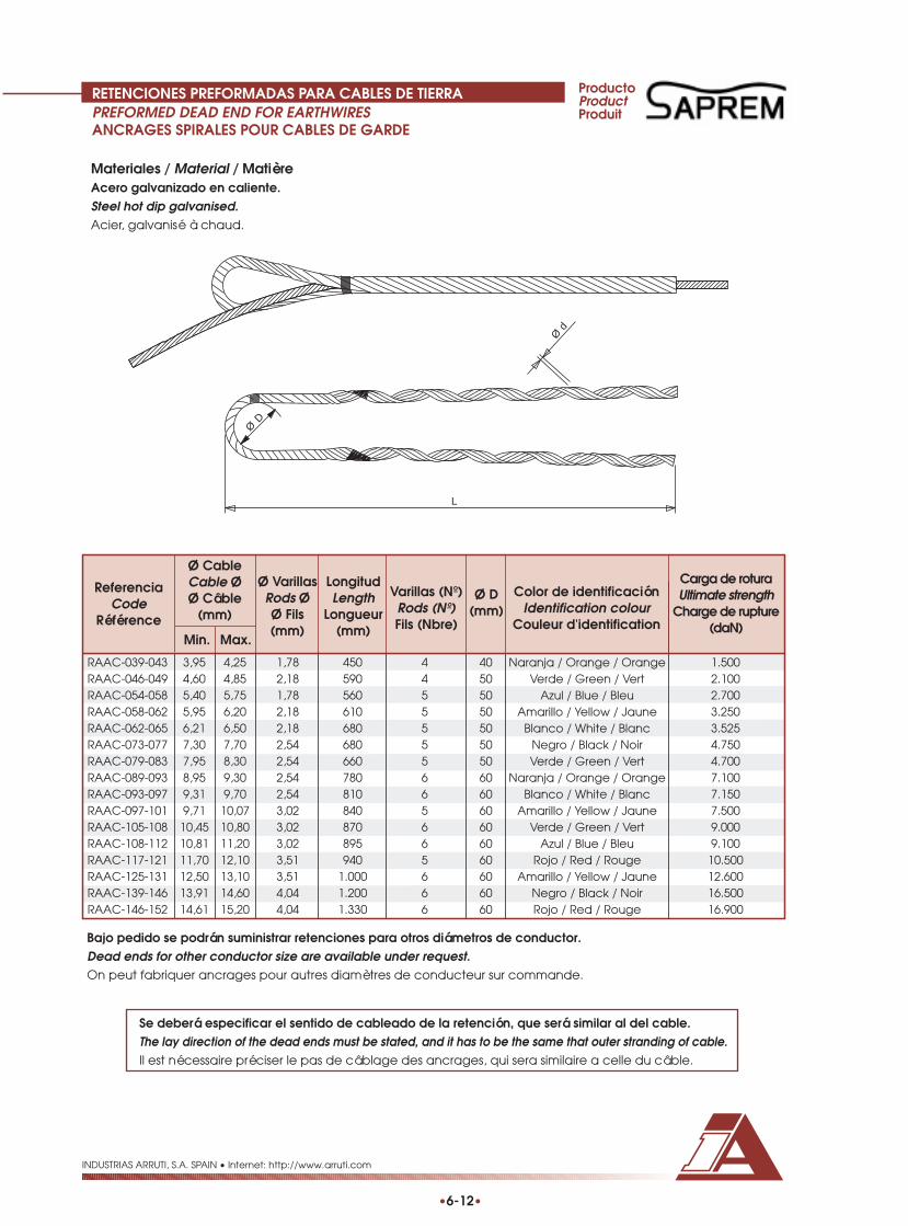
RETENCIONES PREFORMADAS PARA CABLES DE TIERRAPREFORMED DEAD END FOR EARTHWIRESANCRAGES SPIRALES POUR CABLES DE GARDE
•6-12•
INDUSTRIAS ARRUTI, S.A. SPAIN • Internet: http://www.arruti.com
Materiales / Material / MatièreAcero galvanizado en caliente.Steel hot dip galvanised.Acier, galvanisé à chaud.
L
Ød
Ø D
RAAC-039-043 3,95 4,25 1,78 450 4 40 Naranja / Orange / Orange 1.500RAAC-046-049 4,60 4,85 2,18 590 4 50 Verde / Green / Vert 2.100RAAC-054-058 5,40 5,75 1,78 560 5 50 Azul / Blue / Bleu 2.700RAAC-058-062 5,95 6,20 2,18 610 5 50 Amarillo / Yellow / Jaune 3.250RAAC-062-065 6,21 6,50 2,18 680 5 50 Blanco / White / Blanc 3.525RAAC-073-077 7,30 7,70 2,54 680 5 50 Negro / Black / Noir 4.750RAAC-079-083 7,95 8,30 2,54 660 5 50 Verde / Green / Vert 4.700RAAC-089-093 8,95 9,30 2,54 780 6 60 Naranja / Orange / Orange 7.100RAAC-093-097 9,31 9,70 2,54 810 6 60 Blanco / White / Blanc 7.150RAAC-097-101 9,71 10,07 3,02 840 5 60 Amarillo / Yellow / Jaune 7.500RAAC-105-108 10,45 10,80 3,02 870 6 60 Verde / Green / Vert 9.000RAAC-108-112 10,81 11,20 3,02 895 6 60 Azul / Blue / Bleu 9.100RAAC-117-121 11,70 12,10 3,51 940 5 60 Rojo / Red / Rouge 10.500RAAC-125-131 12,50 13,10 3,51 1.000 6 60 Amarillo / Yellow / Jaune 12.600RAAC-139-146 13,91 14,60 4,04 1.200 6 60 Negro / Black / Noir 16.500RAAC-146-152 14,61 15,20 4,04 1.330 6 60 Rojo / Red / Rouge 16.900
ReferenciaCode
Référence
Color de identificaciónIdentification colour
Couleur d'identification
Carga de roturaUltimate strength
Charge de rupture(daN)
Min. Max.
Varillas (Nº)Rods (Nº)Fils (Nbre)
LongitudLength
Longueur(mm)
Ø VarillasRods ØØ Fils(mm)
Ø CableCable ØØ Câble
(mm)Ø D
(mm)
ProductoProductProduit
Bajo pedido se podrán suministrar retenciones para otros diámetros de conductor.Dead ends for other conductor size are available under request.On peut fabriquer ancrages pour autres diamètres de conducteur sur commande.
Se deberá especificar el sentido de cableado de la retención, que será similar al del cable.The lay direction of the dead ends must be stated, and it has to be the same that outer stranding of cable.Il est nécessaire préciser le pas de câblage des ancrages, qui sera similaire a celle du câble.

CONEXIONES
RACCORDS
CONNECTORS

CONEXIONES PARALELAS PARA CONDUCTORES DE ALUMINIOPARALLEL GROOVE CLAMPS FOR ALUMINIUM CONDUCTORS /BLOCS A RAINURES PARALLELES POURCONDUCTEUR D'ALUMINIUM
INDUSTRIAS ARRUTI, S.A. SPAIN • Internet: http://www.arruti.com
•7-1•
Utilización / Usage / UtiisationSe utilizan para derivar o conectar conductores de aluminio. Es importante respetar el par de apriete recomendadopara impedir aflojamiento o daño a los conductores.These clamps are used to connect aluminium conductors. During installation, recommended torque must be respected,in order to avoid conductor damage or slacken.On les emploie pour la dérivation ou connexion des connecteurs d’aluminium. Il est important respecter le coup deserrage recommandé pour éviter que le conducteur soit relâché ou damage.
Materiales / Material / MatièreCuerpo: aleación de aluminio. Tornillería: acero galvanizado en caliente.Body: aluminium alloy. Bolts and nuts: steel hot dip galvanized.Corps: alliage d’aluminium. Boulons et écrous: acier galvanisé à chaud.
ReferenciaCode
Référence
mmPar de apriete
Tightening TorqueCouple de Serrage
(kg.m)
PesoWeightPoids(Kg)B EMin. Max. A C
TornillosBolts
Boulons
ØD ConductorConductor ØD
ØD Conducteur(mm)Fig.
Nº
PC-12,5 / 15 1 12,5 15 67 107 60 M-12 2 5 0,700PC-15 / 18,5 1 15 18,5 67 107 60 M-12 2 5 0,700PC-19 / 22 1 19 22 90 130 70 M-16 2 5 1,250GPC-3 Ø17-20 2 17 20 80 112 40 M-12 3 3 0,950GPC-3 Ø20-23 2 20 23 80 112 40 M-12 3 3 0,950GPC-3 Ø23-25 2 23 25 80 112 40 M-12 3 3 0,950
Bajo pedido se podrán suministrar grapas para otros diámetros de conductor.Connectors for other conductor size are available under request.Sur commande on peut fabriquer blocs pour autres diamètres de conducteur.
Ø D
A
BCE
A
E
B
CC
Ø D
Fig. 1 Fig. 2

CONEXIONES BASCULANTES PARA CONDUCTORES DE ALUMINIOTAP OFF CONNECTORS FOR ALUMINIUM CONDUCTORSBLOCS A RAINURES PARALLELES POUR CONDUCTEUR D'ALUMINIUM
•7-2•
INDUSTRIAS ARRUTI, S.A. SPAIN • Internet: http://www.arruti.com
Utilización / Usage / UtilisationSe utilizan para derivar o conectar conductores de aluminio de distinto diámetro. Es importante respetar el par deapriete recomendado para impedir aflojamiento o daño a los conductores.These clamps are used to connect aluminium conductors with different size. During installation, recommended torquemust be respected, in order to avoid conductor damage or slacken.On les emploie pour la dérivation ou connexion des connecteurs d’aluminium de diffèrent diamètre . Il est importantrespecter le coup de serrage recommandé pour éviter que le conducteur soit relâché ou damage.
Materiales / Material / MatièreCuerpo: aleación de aluminio. Tornillería: acero galvanizado en caliente.Body: aluminium alloy. Bolts and nuts: steel hot dip galvanized.Corps: alliage d’aluminium. Boulons et écrous: acier galvanisé à chaud.
B
A
E
C
Ø D
ReferenciaCode
Référence
mmPeso
WeightPoids(Kg)
Max. B C E NºMin.
TornillosBolts
Boulons
Par de aprieteTightening Torque
Couple de Serrage(kg.m)
Ø ConductorConductor Ø
Ø Conducteur
A
GPC-8 / 16 8 16 54 60 30 M-10 2 3 0,200GPC-11 / 28 11 28 91 115 52 M-12 2 3 0,800

CONEXIONES DE PUESTA A TIERRA PARA CONDUCTORES DE ALUMINIOEARTHING CONNECTORS FOR ALUMINIUM CONDUCTORSBLOCS DE MISE A LA TERRE POUR CONDUCTEUR D'ALUMINIUM
•7-3•
INDUSTRIAS ARRUTI, S.A. SPAIN • Internet: http://www.arruti.com
Utilización / Usage / UtilisationSe utilizan para derivar y conectar a tierra cables de tierra de aluminio. Es importante respetar el par de aprieterecomendado para impedir aflojamiento o daño a los conductores.These clamps are used to connect to earth aluminium earthwires. During installation, recommended torque must berespected, in order to avoid conductor damage or slacken.On les emploie pour la dérivation ou connexion des câbles de garde d’aluminium. Il est important respecter le coupde serrage recommandé pour éviter que le conducteur soit relâché ou damage.
Materiales / Material / MatièreCuerpo: aleación de aluminio. Tornillería: acero galvanizado en caliente.Body: aluminium alloy. Bolts and nuts: steel hot dip galvanized.Corps: alliage d’aluminium. Boulons et écrous: acier galvanisé à chaud.
GCSAL-8 / 14 1 8 14 52 58 65 M-12 2 0,250GCSAL-14 / 18 1 14 18 67 107 60 M-12 2 0,250GCSAL-18 / 24 1 18 24 60 65 80 M-12 3 0,400GCPSAL-8 / 14 2 8 14 50 70 ---- M-12 3 0,350GCPSAL-14 / 18 2 14 18 50 70 ---- M-12 3 0,350GCPSAL-18 / 24 2 18 24 50 70 ---- M-12 3 0,350
ReferenciaCode
Référence
mmPar de apriete
Tightening TorqueCouple de Serrage
(kg.m)
PesoWeightPoids(Kg)B EMin. Max. A C
ØD ConductorConductor ØD
ØD Conducteur(mm)
Fig.
B
C
Ø D
E
A
Ø D
E
A
B
Fig. 1
Fig. 2

CONEXIONES DE PUESTA A TIERRA PARA CABLES DE ACEROEARTHING CONNECTORS FOR STEEL EARTHWIRESBLOCS DE MISE A LA TERRE POUR CABLES DE GARDE DE ACIER
•7-4•
INDUSTRIAS ARRUTI, S.A. SPAIN • Internet: http://www.arruti.com
Utilización / Usage / UtilisationSe utilizan para derivar y conectar a tierra cables de tierra de acero. Es importante respetar el par de aprieterecomendado para impedir aflojamiento o daño a los conductores.These clamps are used to connect to earth steel earthwires. During installation, recommended torque must berespected, in order to avoid conductor damage or slacken.On les emploie pour la dérivation ou connexion des câbles de garde d’acier. Il est important respecter le coup deserrage recommandé pour éviter que le conducteur soit relâché ou damage.
Materiales / Material / MatièreCuerpo: acero forjado galvanizada en caliente. Torni l lería: acero galvanizado en caliente.Body: forged steel, hot dip galvanised. Bolt and nut: steel hot dip galvanized.Corps: acier forge, galvanisé à chaud. Boulon et écrou: acier galvanisé à chaud.
ReferenciaCode
Référence
mmPar de apriete
Tightening TorqueCouple de Serrage
(kg.m)
PesoWeightPoids(Kg)
B EMin. Max. A C
ØD ConductorConductor ØD
ØD Conducteur(mm)
Fig.
GCS-14 1 9 14 44 40 60 M-12 3 0,300GCS-14 / M-16 1 9 14 44 40 60 M-16 3 0,350GCPS-14 2 6 14 49 40 50 M-12 3 0,300GCPS-14 / M-16 2 6 14 49 40 60 M-16 3 0,350GCP-14 3 6 14 49 60 30 M-12 3 0,450
B
A
C
Ø D
E
B
A
E
Ø D
C
A
BC
ØD
E
Fig. 1 Fig. 2 Fig. 3

8 COMPRESIÓN
COMPRESSION
COMPRESSION

INTRODUCCIÓN
INDUSTRIAS ARRUTI, S.A. SPAIN • Internet: http://www.arruti.com
•8-1•
El uso de piezas tubulares comprimidas hexagonalmente como grapas de amarre y empalmes para conductores,es la solución de máximo rendimiento en la regeneración de las características eléctricas y mecánicas del conductor.Esto es debido a que:
• Se mantienen las características mecánicas del conductor, garantizándose que la carga de rotura del conjuntoserá como mínimo del 95% de la carga de rotura nominal del conductor.
• Se asegura la continuidad eléctrica del conductor a través de los accesorios.
• Los valores de radiointerferencia y efecto corona de estos accesorios son iguales y hasta mejores que los del propio conductor, gracias al acabado de las piezas que componen el conjunto y la propia configuración de
la compresión.
Las piezas tubulares (1) que se comprimen sobre los conductores de aluminio o sus aleaciones, son de aluminio puroó aleación de aluminio, según el tipo de conductor al que van destinadas. Las palas de derivación (2) son de aluminiopuro y están fijadas al tubo mediante soldadura eléctrica automática.
Las derivaciones (3) están también fabricadas en base a aluminio puro, realizándose la unión con las palas de lagrapa mediante 2 ó 4 tornillos de acero galvanizado en caliente (dependiendo del tamaño de la grapa), equipadoscon arandelas de asiento y de bloqueo del tipo grower. Las superficies de contacto entre pala (2) y derivación (3)están mecanizadas a fin de garantizar un contacto eléctrico óptimo. Estas superficies son protegidas contra posiblesdaños antes de su instalación mediante la aplicación de una película plástica fácilmente removible. Las derivaciones,una vez colocadas en su posición normal, presentan un ángulo de salida de 30° sobre la vertical, pudiéndose colocaren sentido contrario, en cuyo caso su posición coincidirá con la vertical. En este caso se deberá solicitar el mecanizadode ambas partes de contacto de la derivación.
Las piezas terminales de enganche (4), comúnmente denominadas émbolos, son de acero forjado galvanizado encaliente, con un alargamiento elevado para facilitar la compresión sobre las almas de acero de los conductores.Estos émbolos pueden suministrarse con enganche tipo anilla o tipo horquilla.
Los empalmes están formados por un elemento tubular (5) similar al utilizado para las grapas de amarre y, si elconductor posee además alma de acero, de un manguito interior (6) de acero galvanizado en caliente para fijardicha parte del conductor.
Todas las piezas de compresión llevan marcado indeleblemente la referencia, el cable para el que van destinados,el anagrama de Industrias Arruti y la distancia entre caras de la matriz hexagonal a utilizar para la compresión. Asímismo llevan grabadas las flechas que delimitan las zonas y el sentido de las compresiones a realizar.
A la hora de la instalación, no es necesario el empleo de productos desoxidantes o de relleno ya que, por la propiacompresión, el óxido de aluminio de los alambres del conductor y del interior de los tubos se rompe, obteniéndoseun contacto eléctrico perfecto. No obstante, bajo pedido se podrá suministrar junto con los accesorios grasa decontacto adecuada.
En las siguientes páginas, se incluyen los tipos de fabricación normal para los conductores más comúnmente utilizados.No obstante bajo pedido se pueden fabricar grapas y empalmes de compresión para cualquier conductor.
30°
4 1
2
3
6 5

INTRODUCTION
INDUSTRIAS ARRUTI, S.A. SPAIN • Internet: http://www.arruti.com
•8-2•
The use of hexagonal compressed tubular parts for conductors is the best technical solution from the mechanical andelectrical point of view. They are basically designed for:
• Maintain the mechanical characteristics of the conductor (the compression assembly guarantee 95% of thebreaking load of the conductor).
• Assure the electrical continuity of conductor across the compression parts.
• Reach and in some cases improve corona and RIV values of the conductor, thanks to the accurate finish of partsand the special configuration that the compression provides to the system.
The tubular parts (1) compressed over the aluminium and aluminium alloy conductors, are made of extruded aluminiumor aluminium alloy, according to the type of conductor for which the clamp is intended. The connections (2) for thejumper terminal are made of pure aluminium and they are fixed to the tube through an automatic process of electricwelding.
The jumper terminal (3) is made of pure aluminium too. It is fixed to the clamp body by means of 2 or 4 hot dipgalvanised bolts (according to the clamp size), together with plain and spring washers. Contact surfaces of the jumperterminal and the clamp body are machine finished in order to improve electrical connection. These surfaces areprotected by a plastic film easily removable when used. The jumper terminal, once is mounted on the clamp, is atan angle of 30° to the vertical. It can also be assembled turned; in this way, the terminal is in vertical position. Whenthis position is needed, it must be pointed out in the request, in order to know what contact surface of the jumperterminal must be machined.
The terminal part of the clamps (4) are made of hot dip galvanised forged steel with high elongation properties, fora better performance when is used for compression of steel core of conductor. Steel terminal can be supplied eyetype and clevis type.
The compression joints are composed of an aluminium extruded tube (5) similar to those used for compression clamps,and, if the conductor is of the ACSR type, a hot dip galvanised steel sleeve for fixing steel core.
All parts of the compression fittings are marked indelibly with the catalogue number, the conductor code, the IndustriasArruti logo and the distance across flats of the die to be used. The compression areas are also marked by mean ofarrows that suggest the direction of the compression.
It is not necessary the use of grease compound when assembling a compression fittings, since during compressionthe aluminium oxide that could be present in the conductor strands or into the aluminium tubes is broken, and aperfect electrical contact is obtained. Nevertheless, upon request, we can deliver an appropriate grease compoundwith the fittings.
In the following pages are featured our compression fittings for the most common used conductors. Compressionfittings for other conductors are available under request.
30°
4 1
2
3
6 5

INTRODUCTION
INDUSTRIAS ARRUTI, S.A. SPAIN • Internet: http://www.arruti.com
•8-3•
L’emploie des pièces tubulaires comprimes de façon hexagonale comme les manchons d’ancrage et manchonsde jonction pour conducteurs, est la solution de maximum rendement dans la génération des caractéristiquesélectriques et mécaniques du conducteur. C’est a cause de:
• Les caractéristiques mécaniques du conducteur se maintiennent, et on garantit que la charge rupture du conjoint sera comme minimum le 95% de la charge rupture nominal du conducteur.
• On assure la continuité électrique du conducteur vers ses accessoires.
• Les valeurs de radio interférence et effet couronne des accessoires sont égales ou meilleures que ces du conducteur, grâce à la finition des pièces du conjoint et la propre configuration de la compression.
Les pièces tubulaires (1) qui se compriment sur les conducteurs d’aluminium ou ses alliages, sont d’aluminium (99%de pureté) ou alliage d’aluminium, selon le type de conducteur dans lequel se placent. Les cosses de dérivation (2)sont d’aluminium (99% de pureté), fixés au tube avec soudure électrique automatique.
Les dérivations (3) sont aussi fabriquées sur la basse d’aluminium (99% de pureté), et on fait la connexion aux plagesdu manchon avec 2 o 4 vis d’acier galvanise en chaud (ca dépend de la dimension du manchon), avec rondellesplates et rondelles frein de type Grower. La surface de contact entre plage (2) et dérivation (3) est mécanisée à finde garantir un contact électrique optimal. Ces surfaces sont protégées contre plausibles damages avant son installationavec l’application d’une pellicule de plastique qui se déplace facilement. Une fois que las dérivations ont été placéesá sa position normale, elles ont un angle de sortie de 30° sur la verticale, et on peut las placer au sens contraire, etcomme ça sa position coïncidera avec la verticale. Dans ce cas, l’usinage des deux parties de contact de la dérivationdoit être demandé.
Les terminaisons d’ancrage (4), sont d’acier forgé galvanise á chaud, avec un allongement haut pour faciliter lacompression sur l’âme d’acier des conducteurs. Ces terminaisons peuvent être fournies avec ancrage á œil ou áchapé.
Les manchons de jonction se composent de un élément tubulaire (5) similaire à celle qui s’emploie pour les manchonsd’ancrage et, si le conducteur a âme d’acier, de un fourreau intérieur (6) d’acier galvanise á chaud pour fixer cettepartie au conducteur.
Dans toutes les pièces de compression on marque de façon indélébile la référence de la pièce, le conducteur ouil va être placé, l’anagramme de Industrias Arruti et la distance entre faces de la matrice hexagonale a utiliser pourla compression. De la même façon on marque les flèches que délimitent les zones et le sens des compressions áréaliser.
A l’heure de l’installation, il n’est pas nécessaire l’emploie des produits désoxydants ou de remplissage étant donneque, pour la compression, l’oxyde d’aluminium des fils du conducteur et de l’intérieur des tubes se casse, obtenantun contact électrique parfait. De toute façon, sur commande on peut fournir avec les accessoires une graisse decontact appropriée.
Dans las prochaines pages, il est inclus les types de fabrication normale pour les conducteurs plus utilisés. Cependant,sur commande on peut fabriquer des manchons de jonction pour quelque conducteur.
30°
4 1
2
3
6 5

A
B
L
C
M-1
2
ØD
E
F
G44
,5
44,5
44,5
30°
2
1
3
AB
GRAPAS DE COMPRESION PARA CONDUCTORES DE ALUMINIO-ACEROCOMPRESSION CLAMPS FOR ALUMINIUM CONDUCTORS STEEL REINFORCED (ACSR)MANCHONS D'ANCRAGE POUR CONDUCTEURS D'ALUMINIUM-ACIER
•8-4•
INDUSTRIAS ARRUTI, S.A. SPAIN • Internet: http://www.arruti.com
Materiales:1 – Cuerpo de la grapa: aluminio 10502 – Embolo: acero forjado galvanizado en caliente3 – Derivación: aluminio 10504- Tornillería: acero galvanizado en caliente. Pasador: acero inoxidable
Material:1- Clamp body: aluminium 10502- Steel terminal: Forged steel hot dip galvanized3- Jumper terminal: aluminium 10504- Bolt and nut pin: steel hot dip galvanized. Cotter pin: stainless steel.
Matière.1- Corps du manchon: aluminium 1050
2- Manchon d’acier : acier forgé galvanisé à chaud.
3- Cosse de dérivation : aluminium 1050
4- Boulon et écrou : acier galvanisé à chaud. Goupille: acier inoxydable.
SerieSeriesSérie
mm.
B EA C
E 30 A 22 60 14 525 1,800 19 45 M-16 500 2,000G 38,5 A 23 55 18 600 3,000 22 45 M-16 570 3,500K 46 B 25 70 20 710 5,200 22 45 M-18 665 5,500L 50,4 B 25 70 20 750 5,800 22 45 M-18 705 6,000N 56 B 25 70 20 770 8,000 22 45 M-18 725 7,500P 60 B 25 70 20 830 8,500 22 45 M-18 785 8,000
ø D(mm)
Tipo PalaPad type
Type plage
De AnillaEye typeCeillet
De HorquillaClevis typeType Chape
L F G LPeso
WeightPoids(Kg)
PesoWeightPoids(Kg)

EMPALMES DE COMPRESION A PLENA TRACCION PARA CONDUCTORES DE ALUMINIO-ACEROFULL TENSION COMPRESSION JOINT FOR ALUMINIUM CONDUCTORS STEEL REINFORCED (ACSR)MANCHONS D’JONCTION A PLEINE TRACTION POUR CONDUCTEURS D’ALUMINIUM-ACIER
•8-5•
INDUSTRIAS ARRUTI, S.A. SPAIN • Internet: http://www.arruti.com
Materiales:1 – Empalme exterior: aluminio 10502 – Manguito interior: acero galvanizado en caliente
Material:1- Outer joint: aluminium 10502- Inner joint: steel hot dip galvanized
Matière.1- Manchon extérieur: aluminium 10502- Manchon intérieur : acier galvanisé à chaud.
EMPALMES DE COMPRESION SIN TRACCION PARA CONDUCTORES DE ALUMINIO-ACERONON TENSION COMPRESSION JOINT FOR ALUMINIUM CONDUCTORS STEEL REINFORCED (ACSR)MANCHONS D’JONCTION SANS TRACTION POUR CONDUCTEURS D’ALUMINIUM-ACIER
E 30 600 1,000G 38,5 750 2,000K 46 850 3,000L 50,4 900 3,500N 56 960 4,500P 60 1.080 5,500
SerieSeriesSérie
ØD(mm)
PesoWeightPoids(kg)
L(mm)
Materiales:1 – Empalme exterior: aluminio 1050
Material:1- Outer joint: aluminium 1050
Matière.1- Manchon extérieur: aluminium 1050
E 30 210 0,300G 38,5 240 0,500L 46 285 0,800K 50,4 305 0,900N 56 345 1,400P 60 380 1,700
SerieSeriesSérie
ØD(mm)
PesoWeightPoids(kg)
L(mm)
L
ØD
1 2
1
L
ØD

•8-6•
INDUSTRIAS ARRUTI, S.A. SPAIN • Internet: http://www.arruti.com
GRAPAS DE COMPRESION FINAL PARA CONDUCTORES DE ALUMINIO-ACEROLINE END COMPRESSION CLAMPS FOR ALUMINIUM CONDUCTORS STEEL REINFORCED (ACSR)MANCHONS D’ANCRAGE FINAL POUR CONDUCTEURS D’ALUMINIUM-ACIER
Materiales:1 – Cuerpo de la grapa: aluminio 10502 – Embolo: acero forjado galvanizado en caliente3- Tornillería: acero galvanizado en caliente. Pasador: acero inoxidable
Material:1- Clamp body: aluminium 10502- Steel terminal: Forged steel hot dip galvanized3- Bolt and nut pin: steel hot dip galvanized. Cotter pin: stainless steel.
Matière.1- Corps du manchon: aluminium 10502- Manchon d’acier : acier forgé galvanisé à chaud.3- Boulon et écrou : acier galvanisé à chaud. Goupille: acier inoxydable.
A
B
L
C
D
E
F
G
12
SerieSeriesSérie
mm.
B EA C
E 30 22 60 14 515 1,200 19 45 M-16 490 1,500G 38,5 23 55 18 590 2,000 22 45 M-16 570 2,500K 46 25 70 20 700 3,500 22 45 M-18 655 3,750L 50,4 25 70 20 735 4,000 22 45 M-18 695 4,250N 56 25 70 20 755 4,750 22 45 M-18 715 5,000P 60 25 70 20 815 5,500 22 45 M-18 775 5,750
ø D(mm)
De AnillaEye typeCeillet
De HorquillaClevis typeType Chape
L F G LPeso
WeightPoids(Kg)
PesoWeightPoids(Kg)

•8-7
•
IND
UST
RIA
S A
RR
UTI
, S.A
. SPA
IN •
Inte
rne
t: h
ttp
://w
ww
.arr
uti.
co
m
DesignaciónCode nameDésignation
ø (mm)
PIGEON 12,75 4,25 99,22 C-99 CH-99 EC-99 EC-99-PF CF-99 CFH-99 E 25,5 1095/15 13,60 5,01 109,70 C-109 CH-109 EC-109 EC-109-PF CF-109 CFH-109 E 25,5 10LA-110 14,00 6,00 116,20 C-110 CH-110 EC-110 EC-110-PF CF-110 CFH-110 E 25,5 11CROCUS-116.2 14,00 6,00 116,24 C-115 CH-115 EC-115 EC-115-PF CF-115 CFH-115 E 25,5 11CANNA-116.2 14,00 6,00 116,24 C-116 CH-116 EC-116 EC-116-PF CF-116 CFH-116 E 25,5 11DOG 14,15 4,71 118,50 C-118 CH-118 EC-118 EC-118-PF CF-118 CFH-118 E 25,5 11PENGUIN 14,31 4,77 125,10 C-125 CH-125 EC-125 EC-125-PF CF-125 CFH-125 E 25,5 11SPARVIERO 14,58 4,86 125,70 C-126 CH-126 EC-126 EC-126-PF CF-126 CFH-126 E 25,5 10GUINEA 14,60 8,76 127,55 C-127 CH-127 EC-127 EC-127-PF CF-127 CFH-127 E 25,5 14,5120/20 15,50 5,70 141,40 C-141 CH-141 EC-141 EC-141-PF CF-141 CFH-141 E 25,5 11LA-145 15,75 6,75 147,10 C-145 CH-145 EC-145 EC-145-PF CF-145 CFH-145 E 25,5 12,5CROCUS-147.1 15,75 6,75 147,11 C-147 CH-147 EC-147 EC-147-PF CF-147 CFH-147 E 25,5 12,5OWL 16,09 5,37 152,71 C-152 CH-152 EC-152 EC-152-PF CF-152 CFH-152 E 25,5 11PARTRIDGE 16,28 6,00 157,16 C-157 CH-157 EC-157 EC-157-PF CF-157 CFH-157 E 25,5 12,5125/30 16,30 6,99 157,70 C-158 CH-158 EC-158 EC-158-PF CF-158 CFH-158 E 25,5 12,5DINGO 16,75 3,35 167,50 C-167 CH-167 EC-167 EC-167-PF CF-167 CFH-167 E 25,5 11150/25 17,10 6,30 173,10 C-173 CH-173 EC-173 EC-173-PF CF-173 CFH-173 E 25,5 13,5OSTRICH 17,28 6,36 176,71 C-176 CH-176 EC-176 EC-176-PF CF-176 CFH-176 E 25,5 13,5MERLIN 17,35 3,47 179,93 C-179 CH-179 EC-179 EC-179-PF CF-179 CFH-179 E 25,5 11LA-180 17,50 7,50 181,60 C-180 CH-180 EC-180 EC-180-PF CF-180 CFH-180 E 25,5 13,5CROCUS-181.6 17,50 7,50 181,62 C-181 CH-181 EC-181 EC-181-PF CF-181 CFH-181 E 25,5 13,5PIPER 17,78 7,62 187,48 C-187 CH-187 EC-187 EC-187-PF CF-187 CFH-187 E 25,5 13,5WOLF 18,13 7,08 194,9 C-195 CH-195 EC-195 EC-195-PF CF-195 CFH-195 E 25,5 14,5LINNET 18,31 6,75 198,26 C-198 CH-198 EC-198 EC-198-PF CF-198 CFH-198 E 25,5 13,5
ConductorConductor
Conducteur
Ext.Overall
Ext.
AceroSteelAcier
SecciónArea
Section(mm2)
De AnillaEye type
Type Ceillet
De HorquillaClevis typeType Chape
Grapa de compresiónCompression clampManchon d'ancrage
EmpalmeJoint
Manchon de jonction
Plena TracciónFull tension
Pleine traction
Sin TracciónNon tensionSans traction
Grapa finalLine end clampAncrage final
De HorquillaClevis typeType Chape
De AnillaEye type
Type Ceillet
SerieSeriesSérie
Alum.AceroSteelAcier
Matriz (mm)Die
Matrice
EC
CONDUCTORES DE ALUMINIO-ACEROALUMINIUM CONDUCTORS STEEL REINFORXED (ASCR) / CONDUCTEURS D'ALUMINIUM-ACIER

•8-8
•
IND
UST
RIA
S A
RR
UTI
, S.A
. SPA
IN •
Inte
rne
t: h
ttp
://w
ww
.arr
uti.
co
m
CONDUCTORES DE ALUMINIO-ACEROALUMINIUM CONDUCTORS STEEL REINFORCED (ACSR) / CONDUCTEURS D’ALUMINIUM-ACIER
DesignaciónCode nameDésignation
ø (mm)
170/40 18,90 8,10 211,90 C-212 CH-212 EC-212 EC-212-PF CF-212 CFH-212 G 34,5 14,5185/30 19,00 6,99 213,60 C-213 CH-213 EC-213 EC-213-PF CF-213 CFH-213 G 34,5 14,5ZIGOLO 19,38 7,14 222,39 C-222 CH-222 EC-222 EC-222-PF CF-222 CFH-222 G 34,5 14,5LYNX 19,53 8,37 226,20 C-226 CH-226 EC-226 EC-226-PF CF-226 CFH-226 G 34,5 14,5CROCUS-228 19,60 8,40 227,82 C-228 CH-228 EC-228 EC-228-PF CF-228 CFH-228 G 34,5 14,5BRANT 19,61 6,54 227,55 C-227 CH-227 EC-227 EC-227-PF CF-227 CFH-227 G 34,5 14,5IBIS 19,88 7,32 234,19 C-234 CH-234 EC-234 EC-234-PF CF-234 CFH-234 G 34,5 14,5210/35 20,30 7,47 243,20 C-243 CH-243 EC-243 EC-243-PF CF-243 CFH-243 G 34,5 14,5LARK 20,44 8,76 248,39 C-248 CH-248 EC-248 EC-248-PF CF-248 CFH-248 G 34,5 16PELICAN 20,70 4,14 255,10 C-255 CH-255 EC-255 EC-255-PF CF-255 CFH-255 G 34,5 11PANTHER 21,00 9,00 261,50 C-260 CH-260 EC-260 EC-260-PF CF-260 CFH-260 G 34,5 16230/30 21,00 6,99 260,70 C-261 CH-261 EC-261 EC-261-PF CF-261 CFH-261 G 34,5 14,5210/50 21,00 9,00 261,60 C-262 CH-262 EC-262 EC-262-PF CF-262 CFH-262 G 34,5 16TOUCAN 21,20 6,24 265,42 C-265 CH-265 EC-265 EC-265-PF CF-265 CFH-265 G 34,5 14,5FLICKER 21,49 7,17 272,97 C-273 CH-273 EC-273 EC-273-PF CF-273 CFH-273 G 34,5 14,5HAWK (LA-280) 21,80 8,04 281,10 C-280 CH-280 EC-280 EC-280-PF CF-280 CFH-280 G 34,5 16240/40 21,90 8,04 282,50 C-282 CH-282 EC-282 EC-282-PF CF-282 CFH-282 G 34,5 16LA-250 22,05 9,45 288,35 C-250 CH-250 EC-250 EC-250-PF CF-250 CFH-250 G 34,5 17,5CROCUS-288 22,05 9,45 288,35 C-288 CH-288 EC-288 EC-288-PF CF-288 CFH-288 G 34,5 17,5265/35 22,40 7,47 297,80 C-297 CH-297 EC-297 EC-297-PF CF-297 CFH-297 G 34,5 16HEN 22,40 9,60 298,07 C-298 CH-298 EC-298 EC-298-PF CF-298 CFH-298 G 34,5 17,5PARAKEET 23,22 7,74 318,58 C-318 CH-318 EC-318 EC-318-PF CF-318 CFH-318 G 34,5 16BEAR 23,45 10,05 325,60 C-326 CH-326 EC-326 EC-326-PF CF-326 CFH-326 G 34,5 19DOVE 23,55 8,67 327,94 C-328 CH-328 EC-328 EC-328-PF CF-328 CFH-328 G 34,5 17,5EAGLE 24,22 10,38 347,81 C-347 CH-347 EC-347 EC-347-PF CF-347 CFH-347 G 34,5 19300/50 24,50 9,00 353,70 C-354 CH-354 EC-354 EC-354-PF CF-354 CFH-354 G 34,5 17,5
ConductorConductor
Conducteur
Ext.Overall
Ext.
AceroSteelAcier
SecciónArea
Section(mm2)
De AnillaEye type
Type Ceillet
De HorquillaClevis typeType Chape
Grapa de compresiónCompression clampManchon d'ancrage
EmpalmeJoint
Manchon de jonction
Plena TracciónFull tension
Pleine traction
Sin TracciónNon tensionSans traction
Grapa finalLine end clampAncrage final
De HorquillaClevis typeType Chape
De AnillaEye type
Type Ceillet
SerieSeriesSérie
Alum.AceroSteelAcier
Matriz (mm)Die
Matrice
EC

•8-9
•
IND
UST
RIA
S A
RR
UTI
, S.A
. SPA
IN •
Inte
rne
t: h
ttp
://w
ww
.arr
uti.
co
m
CONDUCTORES DE ALUMINIO-ACEROALUMINIUM CONDUCTORS STEEL REINFORCED (ACSR) / CONDUCTEURS D’ALUMINIUM-ACIER
DesignaciónCode nameDésignation
ø (mm)
340/30 25,00 6,99 369,10 C-369 CH-369 EC-369 EC-369-PF CF-369 CFH-369 K 39,5 16GROSBEAK 25,15 9,27 374,71 C-374 CH-374 EC-374 EC-374-PF CF-374 CFH-374 K 39,5 17,5GULL (LA-380) 25,38 8,46 381,00 C-380 CH-380 EC-380 EC-380-PF CF-380 CFH-380 K 39,5 16CROW 26,28 8,76 409,55 C-409 CH-409 EC-409 EC-409-PF CF-409 CFH-409 K 39,5 16CROCUS-412 26,40 12,00 411,67 C-411 CH-411 EC-411 EC-411-PF CF-411 CFH-411 K 39,5 19385/35 26,70 7,47 420,10 C-420 CH-420 EC-420 EC-420-PF CF-420 CFH-420 K 39,5 16BISON 27,00 9,00 431,30 C-431 CH-431 EC-431 EC-431-PF CF-431 CFH-431 K 39,5 19380/50 27,00 9,00 431,50 C-432 CH-432 EC-432 EC-432-PF CF-432 CFH-432 K 39,5 19REDWING 27,43 11,75 445,16 C-445 CH-445 EC-445 EC-445-PF CF-445 CFH-445 K 39,5 19CONDOR (LA-455) 27,72 9,24 454,50 C-455 CH-455 EC-455 EC-455-PF CF-455 CFH-455 K 39,5 19DRAKE 28,11 10,35 468,45 C-468 CH-468 EC-468 EC-468-PF CF-468 CFH-468 K 39,5 19ZEBRA 28,62 9,54 484,50 C-480 CH-480 EC-480 EC-480-PF CF-480 CFH-480 K 39,5 19450/40 28,70 8,04 488,20 C-488 CH-488 EC-488 EC-488-PF CF-488 CFH-488 K 39,5 16435/55 28,80 9,60 490,60 C-490 CH-490 EC-490 EC-490-PF CF-490 CFH-490 K 39,5 19MALLARD 28,96 12,40 484,71 C-484 CH-484 EC-484 EC-484-PF CF-484 CFH-484 L 45 22CRANE 29,07 9,69 500,68 C-501 CH-501 EC-501 EC-501-PF CF-501 CFH-501 L 45 19CANARY 29,52 9,84 515,16 C-514 CH-514 EC-514 EC-514-PF CF-514 CFH-514 L 45 19RAIL 29,61 7,41 516,84 C-515 CH-515 EC-515 EC-515-PF CF-515 CFH-515 L 45 16495/35 29,90 7,47 528,20 C-528 CH-528 EC-528 EC-528-PF CF-528 CFH-528 L 45 16CAMEL 30,15 10,05 536,80 C-537 CH-537 EC-537 EC-537-PF CF-537 CFH-537 L 45 22CARDINAL (LA-545) 30,42 10,14 547,30 C-540 CH-540 EC-540 EC-540-PF CF-540 CFH-540 L 45 22490/65 30,60 10,20 553,90 C-554 CH-554 EC-554 EC-554-PF CF-554 CFH-554 L 45 22510/45 30,70 8,61 555,50 C-555 CH-555 EC-555 EC-555-PF CF-555 CFH-555 L 45 19CURLEW 31,68 10,56 591,55 C-590 CH-590 EC-590 EC-590-PF CF-590 CFH-590 L 45 22BLUEJAY 31,98 7,98 602,96 C-603 CH-603 EC-603 EC-603-PF CF-603 CFH-603 L 45 19
ConductorConductor
Conducteur
Ext.Overall
Ext.
AceroSteelAcier
SecciónArea
Section(mm2)
De AnillaEye type
Type Ceillet
De HorquillaClevis typeType Chape
Grapa de compresiónCompression clampManchon d'ancrage
EmpalmeJoint
Manchon de jonction
Plena TracciónFull tension
Pleine traction
Sin TracciónNon tensionSans traction
Grapa finalLine end clampAncrage final
De HorquillaClevis typeType Chape
De AnillaEye type
Type Ceillet
SerieSeriesSérie
Alum.AceroSteelAcier
Matriz (mm)Die
Matrice
EC

•8-1
0•
IND
UST
RIA
S A
RR
UTI
, S.A
. SPA
IN •
Inte
rne
t: h
ttp
://w
ww
.arr
uti.
co
m
CONDUCTORES DE ALUMINIO-ACEROALUMINIUM CONDUCTORS STEEL REINFORCED (ACSR) / CONDUCTEURS D’ALUMINIUM-ACIER
DesignaciónCode nameDésignation
ø (mm)
570/40 32,20 8,04 610,30 C-610 CH-610 EC-610 EC-610-PF CF-610 CFH-610 N 49 17,5560/50 32,20 9,00 611,20 C-611 CH-611 EC-611 EC-611-PF CF-611 CFH-611 N 49 19550/70 32,40 10,08 621,30 C-621 CH-621 EC-621 EC-621-PF CF-621 CFH-621 N 49 22BUNTING 33,12 8,28 645,81 C-646 CH-646 EC-646 EC-646-PF CF-646 CFH-646 N 49 19FINCH (LA-635) 32,85 10,95 536,60 C-635 CH-635 EC-635 EC-635-PF CF-635 CFH-635 N 49 22SCISSORTAIL 33,90 7,38 677,67 C-678 CH-678 EC-678 EC-678-PF CF-678 CFH-678 N 49 17,5GRACKLE 33,97 11,35 680,84 C-680 CH-680 EC-680 EC-680-PF CF-680 CFH-680 N 49 22632/45 34,00 8,61 677,40 C-677 CH-677 EC-677 EC-677-PF CF-677 CFH-677 N 49 19BITTERN 34,17 8,55 689,03 C-689 CH-689 EC-689 EC-689-PF CF-689 CFH-689 N 49 19PHEASANT 35,10 11,70 726,19 C-726 CH-726 EC-726 EC-726-PF CF-726 CFH-726 N 49 22DIPPER 35,16 8,76 731,94 C-732 CH-732 EC-732 EC-732-PF CF-732 CFH-732 N 49 19680/85 36,00 12,00 764,80 C-765 CH-765 EC-765 EC-765-PF CF-765 CFH-765 P 52 26MARTIN 36,17 12,05 771,55 C-771 CH-771 EC-771 EC-771-PF CF-771 CFH-771 P 52 26BOBOLINK 36,24 9,06 775,42 C-775 CH-775 EC-775 EC-775-PF CF-775 CFH-775 P 52 22NUTHATCH 37,20 9,30 818,25 C-818 CH-818 EC-818 EC-818-PF CF-818 CFH-818 P 52 22PLOVER 37,24 12,40 816,97 C-817 CH-817 EC-817 EC-817-PF CF-817 CFH-817 P 52 26LAPWING 38,16 9,54 861,16 C-860 CH-860 EC-860 EC-860-PF CF-860 CFH-860 P 52 22PARROT 38,25 12,75 862,19 C-862 CH-862 EC-862 EC-862-PF CF-862 CFH-862 P 52 26FALCON 39,26 13,10 907,81 C-908 CH-908 EC-908 EC-908-PF CF-908 CFH-908 P 52 26
ConductorConductor
Conducteur
Ext.Overall
Ext.
AceroSteelAcier
SecciónArea
Section(mm2)
De AnillaEye type
Type Ceillet
De HorquillaClevis typeType Chape
Grapa de compresiónCompression clampManchon d'ancrage
EmpalmeJoint
Manchon de jonction
Plena TracciónFull tension
Pleine traction
Sin TracciónNon tensionSans traction
Grapa finalLine end clampAncrage final
De HorquillaClevis typeType Chape
De AnillaEye type
Type Ceillet
SerieSeriesSérie
Alum.AceroSteelAcier
Matriz (mm)Die
Matrice
EC

GRAPAS DE COMPRESION PARA CONDUCTORES HOMOGENEOS DE ALUMINIO Y DE ALEACION DE ALUMINIOCOMPRESSION CLAMPS FOR ALL ALUMINIUM AND ALUMINIUM ALLOY CONDUCTORS (AAC,AAAC AND ACAR)MANCHONS D’ANCRAGE POUR CONDUCTEURS HOMOGENES D’ALUMINIUM ET ALLIAGE D’ALUMINIUM
•8-11•
INDUSTRIAS ARRUTI, S.A. SPAIN • Internet: http://www.arruti.com
Materiales:1 – Cuerpo de la grapa: aluminio 1050 (conductores AAC) y aleación de aluminio 6063 (conductores AAAC y ACAR)2 – Embolo: acero forjado galvanizado en caliente3 – Derivación: aluminio 10504- Tornillería: acero galvanizado en caliente. Pasador: acero inoxidable
Material:1- Clamp body: aluminium 1050 for AAC conductors and aluminium alloy 6063 for AAAC and ACAR conductors2- Steel terminal: Forged steel hot dip galvanized3- Jumper terminal: aluminium 10504- Bolt and nut pin: steel hot dip galvanized. Cotter pin: stainless steel.
Matière.1- Corps du manchon: aluminium 1050 (conducteurs AAC) et alliage d’aluminium 6063 (conducteurs AAAC et ACAR)
2- Manchon d’acier : acier forgé galvanisé à chaud.
3- Cosse de dérivation : aluminium 1050
4- Boulon et écrou : acier galvanisé à chaud. Goupille: acier inoxydable.
A
B
L
C
M-1
2
D
E
F
G
30°
2
3
1AB
44,5
44,5
SerieSeriesSérie
mm.
B EA C
E 30 A 22 60 14 385 1,500 19 45 M-16 360 2,000G 38,5 A 23 55 18 435 2,700 22 45 M-16 405 3,200K 46 B 25 70 20 500 4,500 22 45 M-18 460 5,000L 50,4 B 25 70 20 520 5,000 22 45 M-18 480 5,500N 56 B 25 70 20 435 6,750 22 45 M-18 495 6,500P 60 B 25 70 20 590 7,250 22 45 M-18 545 6,750
ø D(mm)
Tipo PalaPad type
Type plage
De AnillaEye type
CEillet
De HorquillaClevis typeType Chape
L F G LPeso
WeightPoids(Kg)
PesoWeightPoids(Kg)

EMPALMES DE COMPRESION A PLENA TRACCION PARA CONDUCTORES HOMOGENEOS DE ALUMINIOY DE ALEACION DE ALUMINIO
FULL TENSION COMPRESSION JOINT FOR ALL ALUMINIUM AND ALUMINIUM ALLOY CONDUCTORS (AACAAAC AND ACAR)MANCHONS D’JONCTION A PLEINE TRACTION POUR CONDUCTEURS HOMOGENES D’ALUMINIUM ETALLIAGE D’ALUMINIUM
•8-12•
INDUSTRIAS ARRUTI, S.A. SPAIN • Internet: http://www.arruti.com
Materiales:1 – Empalme exterior: aluminio 1050 (conductores AAC)
aleación de aluminio 6063 (conductores AAAC y ACAR)
Material:1- Outer joint: aluminium 1050 for AAC conductors aluminium alloy 6063 for AAAC and ACAR conductors
Matière.1- Manchon extérieur: aluminium 1050 pour (conducteurs AAC)
alliage d’aluminium 6063 (conducteurs AAC et ACAR)
E 30 355 0,500G 38,5 425 0,800K 46 485 1,400L 50,4 505 1,500N 56 535 2,000P 60 605 2,500
SerieSeriesSérie
ØD(mm)
PesoWeightPoids(kg)
L(mm)
1
L
ØD
L
ØD
1
EMPALMES DE COMPRESION SIN TRACCION PARA CONDUCTORES HOMOGENEOS DE ALUMINIOY DE ALEACION DE ALUMINIO
NON TENSION COMPRESSION JOINT FOR ALL ALUMINIUM AND ALUMINIUM ALLOY CONDUCTORS (AACAND AAAC)MANCHONS D’JONCTION SANS TRACTION POUR CONDUCTEURS HOMOGENES D’ALUMINIUM ETALLIAGE D’ALUMINIUM
Materiales:1 – Empalme exterior: aluminio 1050
Material:1- Outer joint: aluminium 1050
Matière.1- Manchon extérieur: aluminium 1050
E 30 210 0,300G 38,5 240 0,500K 46 285 0,800L 50,4 305 0,900N 56 345 1,400P 60 380 1,700
SerieSeriesSérie
ØD(mm)
PesoWeightPoids(kg)
L(mm)

•8-13•
INDUSTRIAS ARRUTI, S.A. SPAIN • Internet: http://www.arruti.com
Materiales:1 – Cuerpo de la grapa: aluminio 1050 (conductores AAC) y aleación de aluminio 6063 (conductores AAAC Y ACAR).2 – Embolo: acero forjado galvanizado en caliente.3- Tornillería: acero galvanizado en caliente. Pasador: acero inoxidable
Material:1- Clamp body: aluminium 1050 for AAC conductors and aluminium alloy 6063 for AAAC and ACAR conductors.2- Steel terminal: Forged steel hot dip galvanized.3- Bolt and nut pin: steel hot dip galvanized. Cotter pin: stainless steel.
Matière.1- Corps du manchon: aluminium 1050 (conducteurs AAC) et alliage d'luminium 6063 (conducteurs AAAC et ACAR).2- Manchon d’acier : acier forgé galvanisé à chaud.3- Boulon et écrou : acier galvanisé à chaud. Goupille: acier inoxydable.
A
B
L
C
ØD
E
F
G
12
SerieSeriesSérie
mm.
B EA C
E 30 22 60 14 375 1,000 19 45 M-16 350 1,200G 38,5 23 55 18 425 1,700 22 45 M-16 395 2,300K 46 25 70 20 490 2,800 22 45 M-18 450 3,000L 50,4 25 70 20 510 3,250 22 45 M-18 470 3,500N 56 25 70 20 525 3,750 22 45 M-18 480 4,000P 60 25 70 20 575 4,000 22 45 M-18 535 4,750
ø D(mm)
De AnillaEye type
CEillet
De HorquillaClevis typeType Chape
L F G LPeso
WeightPoids(Kg)
PesoWeightPoids(Kg)
GRAPAS DE COMPRESION FINAL PARA CONDUCTORES HOMOGENEOS DE ALUMINIO Y DEALEACION DE ALUMINIO
LINE END COMPRESSION CLAMPS FOR ALL ALUMINIUM AND ALUMINIUM ALLOY CONDUCTORS(AAC,AAAC AND ACAR)MANCHONS D’ANCRAGE FINAL POUR CONDUCTEURS HOMOGENES D’ALUMINIUM ET ALLIAGED’ALUMINIUM

•8-1
4•
IND
UST
RIA
S A
RR
UTI
, S.A
. SPA
IN •
Inte
rne
t: h
ttp
://w
ww
.arr
uti.
co
m
DesignaciónCode nameDésignation
AAC-93.3 12,50 93,27 C-93-A CH-93-A EC-93-A EC-93-A-PF CF-93-A CFH-93-A E 25,5AAC-95 12,50 93,27 C-95-A CH-95-A EC-95-A EC-95-A-PF CF-95-A CFH-95-A E 25,5OXLIP 13,26 107,23 C-107-A CH-107-A EC-107-A EC-107-A-PF CF-107-A CFH-107-A E 25,5L-110 14,00 117,00 C-110-A CH-110-A EC-110-A EC-110-A-PF CF-110-A CFH-110-A E 25,5AAC-117 14,00 116,98 C-117-A CH-117-A EC-117-A EC-117-A-PF CF-117-A CFH-117-A E 25,5AAC-120 14,00 117,00 C-120-A CH-120-A EC-120-A EC-120-A-PF CF-120-A CFH-120-A E 25,5DAISY 14,90 135,16 C-135-A CH-135-A EC-135-A EC-135-A-PF CF-135-A CFH-135-A E 25,5AAC-150 15,70 147,10 C-150-A CH-150-A EC-150-A EC-150-A-PF CF-150-A CFH-150-A E 25,5L-145 15,75 148,10 C-145-A CH-145-A EC-145-A EC-145-A-PF CF-145-A CFH-145-A E 25,5AAC-148 15,75 148,01 C-148-A CH-148-A EC-148-A EC-148-A-PF CF-148-A CFH-148-A E 25,5TULIP 16,91 170,45 C-170-A CH-170-A EC-170-A EC-170-A-PF CF-170-A CFH-170-A E 25,5AAC-185 17,50 181,60 C-185-A CH-185-A EC-185-A EC-185-A-PF CF-185-A CFH-185-A E 25,5L-180 17,75 188,10 C-180-A CH-180-A EC-180-A EC-180-A-PF CF-180-A CFH-180-A E 25,5AAC-188 17,75 188,06 C-188-A CH-188-A EC-188-A EC-188-A-PF CF-188-A CFH-188-A E 25,5CANNA 18,36 201,42 C-201-A CH-201-A EC-201-A EC-201-A-PF CF-201-A CFH-201-A E 25,5AAC-228 19,60 227,83 C-228-A CH-228-A EC-228-A EC-228-A-PF CF-228-A CFH-228-A G 34,5COSMOS 20,12 241,68 C-241-A CH-241-A EC-241-A EC-241-A-PF CF-241-A CFH-241-A G 34,5AAC-240 20,20 242,50 C-240-A CH-240-A EC-240-A EC-240-A-PF CF-240-A CFH-240-A G 34,5L-280 21,70 279,30 C-280-A CH-280-A EC-280-A EC-280-A-PF CF-280-A CFH-280-A G 34,5DAHLIA 21,73 282,00 C-282-A CH-282-A EC-282-A EC-282-A-PF CF-282-A CFH-282-A G 34,5AAC-288 22,05 288,34 C-288-A CH-288-A EC-288-A EC-288-A-PF CF-288-A CFH-288-A G 34,5AAC-300 22,50 299,40 C-300-A CH-300-A EC-300-A EC-300-A-PF CF-300-A CFH-300-A G 34,5MEADOWSWEET 22,63 304,00 C-304-A CH-304-A EC-304-A EC-304-A-PF CF-304-A CFH-304-A G 34,5ORCHID 23,31 322,25 C-322-A CH-322-A EC-322-A EC-322-A-PF CF-322-A CFH-322-A G 34,5VERBENA 24,45 354,71 C-354-A CH-354-A EC-354-A EC-354-A-PF CF-354-A CFH-354-A G 34,5VIOLET 24,74 362,58 C-362-A CH-362-A EC-362-A EC-362-A-PF CF-362-A CFH-362-A G 34,5AAC-366 24,85 366,22 C-366-A CH-366-A EC-366-A EC-366-A-PF CF-366-A CFH-366-A G 34,5
ConductorConductor
Conducteur
Ø Ext.Overall Ø
Ø Ext.(mm)
SecciónArea
Section(mm2)
De AnillaEye type
Type Ceillet
De HorquillaClevis typeType Chape
Grapa de compresiónCompression clampManchon d'ancrage
EmpalmeJoint
Manchon de jonction
Plena TracciónFull tension
Pleine traction
Sin TracciónNon tensionSans traction
Grapa finalLine end clampAncrage final
De HorquillaClevis typeType Chape
De AnillaEye type
Type Ceillet
SerieSeriesSérie
AlumimioAluminium
Matriz (mm)Die
Matrice
EC
CONDUCTORES HOMOGENEOS DE ALUMINIOALL ALUMINIUM CONDUCTORS (AAC) / CONDUCTEURS HOMOGENES D’ALUMINIUM

•8-1
5•
IND
UST
RIA
S A
RR
UTI
, S.A
. SPA
IN •
Inte
rne
t: h
ttp
://w
ww
.arr
uti.
co
m
CONDUCTORES HOMOGENEOS DE ALUMINIOALL ALUMINIUM CONDUCTORS (AAC) / CONDUCTEURS HOMOGENES D’ALUMINIUM
DesignaciónCode nameDésignation
PETUNIA 25,32 380,00 C-380-A CH-380-A EC-380-A EC-380-A-PF CF-380-A CFH-380-A K 39,5L-400 25,38 381,00 C-381-A CH-381-A EC-381-A EC-381-A-PF CF-381-A CFH-381-A K 39,5AAC-400 26,00 400,10 C-400-A CH-400-A EC-400-A EC-400-A-PF CF-400-A CFH-400-A K 39,5ARBUTUS 26,06 402,84 C-403-A CH-403-A EC-403-A EC-403-A-PF CF-403-A CFH-403-A K 39,5L-450 27,72 454,50 C-450-A CH-450-A EC-450-A EC-450-A-PF CF-450-A CFH-450-A K 39,5AAC-475 28,35 475,38 C-475-A CH-475-A EC-475-A EC-475-A-PF CF-475-A CFH-475-A K 39,5MAGNOLIA 28,55 483,42 C-483-A CH-483-A EC-483-A EC-483-A-PF CF-483-A CFH-483-A K 39,5AAC-500 29,10 499,80 C-500-A CH-500-A EC-500-A EC-500-A-PF CF-500-A CFH-500-A K 39,5CAMELLIA 29,36 506,71 C-506-A CH-506-A EC-506-A EC-506-A-PF CF-506-A CFH-506-A K 39,5BLUEBELL 29,72 523,68 C-523-A CH-523-A EC-523-A EC-523-A-PF CF-523-A CFH-523-A L 45LARKSPUR 29,76 523,68 C-524-A CH-524-A EC-524-A EC-524-A-PF CF-524-A CFH-524-A L 45L-550 30,42 547,30 C-550-A CH-550-A EC-550-A EC-550-A-PF CF-550-A CFH-550-A L 45MARIGOLD 30,89 563,93 C-564-A CH-564-A EC-564-A EC-564-A-PF CF-564-A CFH-564-A L 45HAWTHORN 31,05 604,26 C-605-A CH-605-A EC-605-A EC-605-A-PF CF-605-A CFH-605-A L 45AAC-604 31,95 603,78 C-604-A CH-604-A EC-604-A EC-604-A-PF CF-604-A CFH-604-A L 45AAC-625 32,60 626,20 C-625-A CH-625-A EC-625-A EC-625-A-PF CF-625-A CFH-625-A N 49L-630 32,85 638,30 C-630-A CH-630-A EC-630-A EC-630-A-PF CF-630-A CFH-630-A N 49NARCISSUS 33,02 644,51 C-644-A CH-644-A EC-644-A EC-644-A-PF CF-644-A CFH-644-A N 49COLUMBINE 34,01 684,84 C-685-A CH-685-A EC-685-A EC-685-A-PF CF-685-A CFH-685-A N 49CARNATION 35,03 725,10 C-725-A CH-725-A EC-725-A EC-725-A-PF CF-725-A CFH-725-A P 52GLADIOULUS 35,09 765,35 C-765-A CH-765-A EC-765-A EC-765-A-PF CF-765-A CFH-765-A P 52COREOPSIS 36,51 805,68 C-805-A CH-805-A EC-805-A EC-805-A-PF CF-805-A CFH-805-A P 52AAC-800 36,80 802,10 C-800-A CH-800-A EC-800-A EC-800-A-PF CF-800-A CFH-800-A P 52JESSAMINE 38,73 886,71 C-886-A CH-886-A EC-886-A EC-886-A-PF CF-886-A CFH-886-A P 52AAC-1000 41,10 999,70 C-1000-A CH-1000-A EC-1000-A EC-1000-A-PF CF-1000-A CFH-1000-A P 52
ConductorConductor
Conducteur
Ø Ext.Overall Ø
Ø Ext.(mm)
SecciónArea
Section(mm2)
De AnillaEye type
Type Ceillet
De HorquillaClevis typeType Chape
Grapa de compresiónCompression clampManchon d'ancrage
EmpalmeJoint
Manchon de jonction
Plena TracciónFull tension
Pleine traction
Sin TracciónNon tensionSans traction
Grapa finalLine end clampAncrage final
De HorquillaClevis typeType Chape
De AnillaEye type
Type Ceillet
SerieSeriesSérie
AlumimioAluminium
Matriz (mm)Die
Matrice
EC

•8-1
6•
IND
UST
RIA
S A
RR
UTI
, S.A
. SPA
IN •
Inte
rne
t: h
ttp
://w
ww
.arr
uti.
co
m
CONDUCTORES HOMOGENEOS DE ALEACION DEALUMINIOALL ALUMINIUM ALLOY CONDUCTORS (AAAC) / CONDUCTEURS HOMOGENES D’ALLIAGE D’ALUMINIUM
DesignaciónCode nameDésignation
ASTER-93-3 12,50 93,27 C-93-AA CH-93-AA EC-93-AA EC-93-AA-PF CF-93-AA CFH-93-AA E 25,5AAAC-95 12,50 93,27 C-95-AA CH-95-AA EC-95-AA EC-95-AA-PF CF-95-AA CFH-95-AA E 25,5AMHERST 12,75 99,22 C-99-AA CH-99-AA EC-99-AA EC-99-AA-PF CF-99-AA CFH-99-AA E 25,5OAK 13,95 118,90 C-119-AA CH-119-AA EC-119-AA EC-119-AA-PF CF-119-AA CFH-119-AA E 25,5D-110 14,00 117,00 C-110-AA CH-110-AA EC-110-AA EC-110-AA-PF CF-110-AA CFH-110-AA E 25,5ASTER-117 14,00 116,98 C-117-AA CH-117-AA EC-117-AA EC-117-AA-PF CF-117-AA CFH-117-AA E 25,5AAAC-120 14,00 117,00 C-120-AA CH-120-AA EC-120-AA EC-120-AA-PF CF-120-AA CFH-120-AA E 25,5ALLIANCE 14,31 125,10 C-125-AA CH-125-AA EC-125-AA EC-125-AA-PF CF-125-AA CFH-125-AA E 25,5AAAC-150 15,70 147,10 C-150-AA CH-150-AA EC-150-AA EC-150-AA-PF CF-150-AA CFH-150-AA E 25,5D-145 15,75 148,10 C-145-AA CH-145-AA EC-145-AA EC-145-AA-PF CF-145-AA CFH-145-AA E 25,5ASTER-148 15,75 148,01 C-148-AA CH-148-AA EC-148-AA EC-148-AA-PF CF-148-AA CFH-148-AA E 25,5MULBERRY 15,90 151,10 C-151-AA CH-151-AA EC-151-AA EC-151-AA-PF CF-151-AA CFH-151-AA E 25,5BUTTE 16,30 158,60 C-158-AA CH-158-AA EC-158-AA EC-158-AA-PF CF-158-AA CFH-158-AA E 25,5AAAC-160 16,35 160,00 C-160-AA CH-160-AA EC-160-AA EC-160-AA-PF CF-160-AA CFH-160-AA E 25,5ASH 17,40 180,70 C-182-AA CH-182-AA EC-182-AA EC-182-AA-PF CF-182-AA CFH-182-AA E 25,5AAAC-185 17,50 181,60 C-185-AA CH-185-AA EC-185-AA EC-185-AA-PF CF-185-AA CFH-185-AA E 25,5ASTER-181-6 17,50 181,62 C-181-AA CH-181-AA EC-181-AA EC-181-AA-PF CF-181-AA CFH-181-AA E 25,5D-180 17,75 188,10 C-180-AA CH-180-AA EC-180-AA EC-180-AA-PF CF-180-AA CFH-180-AA E 25,5CANTON 18,30 199,90 C-200-AA CH-200-AA EC-200-AA EC-200-AA-PF CF-200-AA CFH-200-AA E 25,5ELM 18,80 211,00 C-211-AA CH-211-AA EC-211-AA EC-211-AA-PF CF-211-AA CFH-211-AA E 25,5ASTER-228 19,60 227,83 C-228-AA CH-228-AA EC-228-AA EC-228-AA-PF CF-228-AA CFH-228-AA G 34,5CAIRO 19,88 235,80 C-236-AA CH-236-AA EC-236-AA EC-236-AA-PF CF-236-AA CFH-236-AA G 34,5POPLAR 20,09 239,00 C-239-AA CH-239-AA EC-239-AA EC-239-AA-PF CF-239-AA CFH-239-AA G 34,5AAAC-240 20,20 242,50 C-240-AA CH-240-AA EC-240-AA EC-240-AA-PF CF-240-AA CFH-240-AA G 34,5D-280 21,70 279,30 C-280-AA CH-280-AA EC-280-AA EC-280-AA-PF CF-280-AA CFH-280-AA G 34,5
ConductorConductor
Conducteur
Ø Ext.Overall Ø
Ø Ext.(mm)
SecciónArea
Section(mm2)
De AnillaEye type
Type Ceillet
De HorquillaClevis typeType Chape
Grapa de compresiónCompression clampManchon d'ancrage
EmpalmeJoint
Manchon de jonction
Plena TracciónFull tension
Pleine traction
Sin TracciónNon tensionSans traction
Grapa finalLine end clampAncrage final
De HorquillaClevis typeType Chape
De AnillaEye type
Type Ceillet
SerieSeriesSérie
AlumimioAluminium
Matriz (mm)Die
Matrice
EC

•8-1
7•
IND
UST
RIA
S A
RR
UTI
, S.A
. SPA
IN •
Inte
rne
t: h
ttp
://w
ww
.arr
uti.
co
m
CONDUCTORES HOMOGENEOS DE ALEACION DE ALUMINIOALL ALUMINIUM ALLOY CONDUCTORS (AAAC) / CONDUCTEURS HOMOGENES D’ALLIAGE D’ALUMINIUM
DesignaciónCode nameDésignation
DARIEN 21,79 283,50 C-283-AA CH-283-AA EC-283-AA EC-283-AA-PF CF-283-AA CFH-283-AA G 34,5ASTER-288 22,05 288,34 C-288-AA CH-288-AA EC-288-AA EC-288-AA-PF CF-288-AA CFH-288-AA G 34,5AAAC-300 22,50 299,40 C-300-AA CH-300-AA EC-300-AA EC-300-AA-PF CF-300-AA CFH-300-AA G 34,5SYCAMORE 22,61 303,00 C-303-AA CH-303-AA EC-303-AA EC-303-AA-PF CF-303-AA CFH-303-AA G 34,5ELGIN 23,54 330,60 C-330-AA CH-330-AA EC-330-AA EC-330-AA-PF CF-330-AA CFH-330-AA G 34,5UPAS 24,71 362,10 C-362-AA CH-362-AA EC-362-AA EC-362-AA-PF CF-362-AA CFH-362-AA G 34,5ASTER-366 24,85 366,22 C-366-AA CH-366-AA EC-366-AA EC-366-AA-PF CF-366-AA CFH-366-AA G 34,5FLINT 25,16 375,30 C-375-AA CH-375-AA EC-375-AA EC-375-AA-PF CF-375-AA CFH-375-AA K 39,5D-400 25,38 381,00 C-381-AA CH-381-AA EC-381-AA EC-381-AA-PF CF-381-AA CFH-381-AA K 39,5AAAC-400 26,00 400,10 C-400-AA CH-400-AA EC-400-AA EC-400-AA-PF CF-400-AA CFH-400-AA K 39,5D-450 27,72 454,50 C-450-AA CH-450-AA EC-450-AA EC-450-AA-PF CF-450-AA CFH-450-AA K 39,5GREELEY 28,14 469,80 C-470-AA CH-470-AA EC-470-AA EC-470-AA-PF CF-470-AA CFH-470-AA K 39,5YEW 28,42 479,90 C-480-AA CH-480-AA EC-480-AA EC-480-AA-PF CF-480-AA CFH-480-AA K 39,5AAAC-500 29,10 499,80 C-500-AA CH-500-AA EC-500-AA EC-500-AA-PF CF-500-AA CFH-500-AA K 39,5D-550 30,42 547,30 C-550-AA CH-550-AA EC-550-AA EC-550-AA-PF CF-550-AA CFH-550-AA L 45ASTER-570 31,05 570,22 C-570-AA CH-570-AA EC-570-AA EC-570-AA-PF CF-570-AA CFH-570-AA N 49RUBUS 31,50 586,60 C-586-AA CH-586-AA EC-586-AA EC-586-AA-PF CF-586-AA CFH-586-AA N 49AAAC-625 32,60 626,20 C-625-AA CH-625-AA EC-625-AA EC-625-AA-PF CF-625-AA CFH-625-AA N 49D-630 32,85 638,30 C-630-AA CH-630-AA EC-630-AA EC-630-AA-PF CF-630-AA CFH-630-AA N 49AAAC-800 36,90 802,09 C-800-AA CH-800-AA EC-800-AA EC-800-AA-PF CF-800-AA CFH-800-AA P 52
ConductorConductor
Conducteur
Ø Ext.Overall Ø
Ø Ext.(mm)
SecciónArea
Section(mm2)
De AnillaEye type
Type Ceillet
De HorquillaClevis typeType Chape
Grapa de compresiónCompression clampManchon d'ancrage
EmpalmeJoint
Manchon de jonction
Plena TracciónFull tension
Pleine traction
Sin TracciónNon tensionSans traction
Grapa finalLine end clampAncrage final
De HorquillaClevis typeType Chape
De AnillaEye type
Type Ceillet
SerieSeriesSérie
AlumimioAluminium
Matriz (mm)Die
Matrice
EC

•8-1
8•
IND
UST
RIA
S A
RR
UTI
, S.A
. SPA
IN •
Inte
rne
t: h
ttp
://w
ww
.arr
uti.
co
m
CONDUCTORES DE ALUMINIO REFORZADOS CON ALEACION DE ALUMINIOALUMINIUM CONDUCTORS ALLOY REINFORCED (ACAR) / CONDUCTEURS D’ALUMINIUM REFORCES AVEC ALLIAGE D'ALUMINIUM
DesignaciónCode nameDésignation
195.7 12,74 99,10 C-98-AA CH-98-AA EC-98-AA EC-98-AA-PF CF-98-AA CFH-98-AA E 25,54/0 13,25 107,00 C-107-AA CH-107-AA EC-107-AA EC-107-AA-PF CF-107-AA CFH-107-AA E 25,5246.9 14,31 125,00 C-124-AA CH-124-AA EC-124-AA EC-124-AA-PF CF-124-AA CFH-124-AA E 25,5250 14,56 127,00 C-127-AA CH-127-AA EC-127-AA EC-127-AA-PF CF-127-AA CFH-127-AA E 25,5300 15,96 152,00 C-152-AA CH-152-AA EC-152-AA EC-152-AA-PF CF-152-AA CFH-152-AA E 25,5350 17,24 177,00 C-177-AA CH-177-AA EC-177-AA EC-177-AA-PF CF-177-AA CFH-177-AA E 25,5400 18,44 203,00 C-203-AA CH-203-AA EC-203-AA EC-203-AA-PF CF-203-AA CFH-203-AA E 25,5450 19,55 228,00 C-227-AA CH-227-AA EC-227-AA EC-227-AA-PF CF-227-AA CFH-227-AA G 34,5500 20,60 253,00 C-253-AA CH-253-AA EC-253-AA EC-253-AA-PF CF-253-AA CFH-253-AA G 34,5550 21,66 279,00 C-279-AA CH-279-AA EC-279-AA EC-279-AA-PF CF-279-AA CFH-279-AA G 34,5600 22,58 304,00 C-304-AA CH-304-AA EC-304-AA EC-304-AA-PF CF-304-AA CFH-304-AA G 34,5650 23,57 329,00 C-329-AA CH-329-AA EC-329-AA EC-329-AA-PF CF-329-AA CFH-329-AA G 34,5700 24,46 355,00 C-355-AA CH-355-AA EC-355-AA EC-355-AA-PF CF-355-AA CFH-355-AA G 34,5750 25,32 380,00 C-380-AA CH-380-AA EC-380-AA EC-380-AA-PF CF-380-AA CFH-380-AA K 39,5800 26,15 405,00 C-405-AA CH-405-AA EC-405-AA EC-405-AA-PF CF-405-AA CFH-405-AA K 39,5850 26,95 431,00 C-431-AA CH-431-AA EC-431-AA EC-431-AA-PF CF-431-AA CFH-431-AA K 39,5900 27,75 456,00 C-456-AA CH-456-AA EC-456-AA EC-456-AA-PF CF-456-AA CFH-456-AA K 39,5950 28,50 481,00 C-481-AA CH-481-AA EC-481-AA EC-481-AA-PF CF-481-AA CFH-481-AA K 39,51.000 29,30 507,00 C-507-AA CH-507-AA EC-507-AA EC-507-AA-PF CF-507-AA CFH-507-AA K 39,51.100 30,65 557,00 C-557-AA CH-557-AA EC-557-AA EC-557-AA-PF CF-557-AA CFH-557-AA L 451.200 32,10 608,00 C-608-AA CH-608-AA EC-608-AA EC-608-AA-PF CF-608-AA CFH-608-AA L 451.250 32,70 633,00 C-633-AA CH-633-AA EC-633-AA EC-633-AA-PF CF-633-AA CFH-633-AA N 491.300 33,33 659,00 C-659-AA CH-659-AA EC-659-AA EC-659-AA-PF CF-659-AA CFH-659-AA N 491.400 34,65 709,00 C-709-AA CH-709-AA EC-709-AA EC-709-AA-PF CF-709-AA CFH-709-AA N 491.500 35,85 760,00 C-760-AA CH-760-AA EC-760-AA EC-760-AA-PF CF-760-AA CFH-760-AA P 521.600 37,05 811,00 C-811-AA CH-811-AA EC-811-AA EC-811-AA-PF CF-811-AA CFH-811-AA P 521.700 38,15 861,00 C-861-AA CH-861-AA EC-861-AA EC-861-AA-PF CF-861-AA CFH-861-AA P 521.750 38,75 887,00 C-887-AA CH-887-AA EC-887-AA EC-887-AA-PF CF-887-AA CFH-887-AA P 52
ConductorConductor
Conducteur
Ø Ext.Overall Ø
Ø Ext.(mm)
SecciónArea
Section(mm2)
De AnillaEye type
Type Ceillet
De HorquillaClevis typeType Chape
Grapa de compresiónCompression clampManchon d'ancrage
EmpalmeJoint
Manchon de jonction
Plena TracciónFull tension
Pleine traction
Sin TracciónNon tensionSans traction
Grapa finalLine end clampAncrage final
De HorquillaClevis typeType Chape
De AnillaEye type
Type Ceillet
SerieSeriesSérie
AlumimioAluminium
Matriz (mm)Die
Matrice
EC

GRAPAS DE COMPRESION PARA CONDUCTORES DE ALUMINIO DE DIAMETRO HASTA 12,50 mmCOMPRESSION CLAMPS FOR ALUMINIUM CONDUCTORS WITH OVERALL DIAMETER UP TO 12,5 mmMANCHONS D’ANCRAGE POUR CONDUCTEURS D’ALUMINIUM DE DIAMETRE JUSQUA 12,50 mm
•8-19•
INDUSTRIAS ARRUTI, S.A. SPAIN • Internet: http://www.arruti.com
Materiales:1 - Cuerpo de la grapa: aluminio 10502 - Embolo: acero galvanizado en caliente3 - Derivación: aluminio 10504 - Tornillería: acero galvanizado en caliente.
Pasador: acero inoxidable
Material:1 - Clamp body: aluminium 10502 - Steel terminal: steel hot dip galvanized3 - Jumper terminal: aluminium 10504 - Bolt and nut pin: steel hot dip galvanized.
Cotter pin: stainless steel.
Matière.
1 - Corps du manchon: aluminium 10502 - Manchon d’acier : acier galvanisé à chaud.3 - Cosse de dérivation : aluminium 10504 - Boulon et écrou : acier galvanisé à chaud.
Goupille: acier inoxydable.
Materiales:1 – Empalme exterior: aluminio 1050
Material:1- Outer joint: aluminium 1050
Matière.1- Manchon extérieur: aluminium 1050
L
ØD
EMPALMES DE COMPRESION A PLENA TRACCION PARA CONDUCTORES DE ALUMINIO DEDIAMETRO HASTA 12,50 mm
FULL TENSION COMPRESSION JOINT FOR ALUMINIUM CONDUCTORS WITH OVERALL DIAMETER UPTO 12,50 mmMANCHONS D’JONCTION A PLEINE TRACTION POUR CONDUCTEURS D’ALUMINIUM DE DIAMETREJUSQUA 12,50 mm
2
3
1Ø16
19
40
40
L
ØD
30°
M-1
2
30
B 20,6 270 300 1,000D 25,4 315 315 1,200
SerieSeriesSérie
PesoWeightPoids(kg)
mm
ØD LAAAC ACSR
B 20,6 215 315 0,150 - 0,250D 25,4 260 350 0,250 - 0,350
SerieSeriesSérie
PesoWeightPoids(kg)
mm
ØD LAAAC ACSR

GRAPAS DE COMPRESION PARA CONDUCTORES DE ALUMINIO DE DIAMETRO HASTA 12,50 mmCOMPRESSION CLAMPS FOR ALUMINIUM CONDUCTORS WITH OVERALL DIAMETER UP TO 12,5 mmMANCHONS D’ANCRAGE POUR CONDUCTEURS D’ALUMINIUM DE DIAMETRE JUSQUA 12,50 mm
•8-20•
INDUSTRIAS ARRUTI, S.A. SPAIN • Internet: http://www.arruti.com
DesignaciónCode nameDésignation
AAC-25 6,30 24,25 CH-25-A EC-25-A B 17,5AAAC-25 6,30 24,25 CH-25-AA EC-25-AA B 17,5ACSR SQUIRREL 6,33 24,43 CH-24 EC-24 B 17,5ACSR SWAN 6,36 24,71 CH-25 EC-25 B 17,5AAAC ALTON 6,36 24,71 CH-24-AA EC-24-AA B 17,5AAC GNAT 6,60 26,80 CH-26-A EC-26-A B 17,5AAC L-28 6,75 27,80 CH-28-A EC-28-A B 17,5AAAC D-28 6,75 27,80 CH-28-AA EC-28-AA B 17,5AAC-27.8 6,75 27,83 CH-27-A EC-27-A B 17,5ACSR 25/4.0 6,80 27,80 CH-27 EC-27 B 17,5AAAC ALMOND 7,02 30,10 CH-30-AA EC-30-AA B 17,5ACSR GOPHER 7,08 30,62 CH-29 EC-29 B 17,5ACSR LA-30 7,14 31,10 CH-30 EC-30 B 17,5ACSR SWALLOW 7,14 31,10 CH-31 EC-31 B 17,5AAC IRIS 7,42 33,61 CH-33-A EC-33-A B 17,5AAC-34.4 7,50 34.36 CH-34-A EC-34-A B 17,5ASTER-34.4 7,50 34.36 CH-34-AA EC-34-AA B 17,5AAC-35 7,50 34,36 CH-35-A EC-35-A B 17,5AAAC-35 7,50 34,36 CH-35-AA EC-35-AA B 17,5AAAC CEDAR 7,62 35,50 CH-36-AA EC-36-AA B 17,5ACSR WEASEL 7,77 36,88 CH-37 EC-37 B 17,5AAC MOSQUITO 7,80 37,00 CH-37-A EC-37-A B 17,5ACSR SPARROW 8,01 39,22 CH-39 EC-39 B 17,5AAAC AMES 8,02 39,22 CH-39-AA EC-39-AA B 17,5ACAR-77.5 8,03 39,30 CH-38-AA EC-38-AA B 17,5ACSR 35/6.0 8,10 40,00 CH-40 EC-40 B 17,5AAAC-40 8,10 40,00 CH-41-AA EC-41-AA B 17,5ACSR SPARATE 8,24 42,13 CH-42 EC-42 B 17,5AAC PANSY 8,33 42,39 CH-42-A EC-42-A B 17,5ACSR FOX 8,37 42,77 CH-43 EC-43 B 17,5AAC L-40 8,40 43,10 CH-40-A EC-40-A B 17,5AAC D-40 8,40 43,10 CH-40-AA EC-40-AA B 17,5AAC-43.1 8,40 43,10 CH-43-A EC-43-A B 17,5AAAC FIR 8,85 47,80 CH-48AA EC-48-AA B 17,5ACSR FERRET 9,00 49,48 CH-49 EC-49 B 17,5AAC-50 9,00 49,48 CH-50-A EC-50-A B 17,5AAAC-50 9,00 49,48 CH-50-AA EC-50-AA B 17,5ACSR ROBIN 9,00 49,49 CH-50 EC-50 B 17,5
ConductorConductor
Conducteur
Ø Ext.Overall Ø
Ø Ext.(mm)
SecciónArea
Section(mm2)
De HorquillaClevis typeType Chape
Grapaclamp
Manchond'ancrage
EmpalmeJoint
Manchonde jonction
Plena TracciónFull tension
Pleine traction
SerieSeriesSérie
AlumimioAluminium
Matriz (mm)Die
Matrice
EC

•8-21•
GRAPAS DE COMPRESION PARA CONDUCTORES DE ALUMINIO DE DIAMETRO HASTA 12,50 mmCOMPRESSION CLAMPS FOR ALUMINIUM CONDUCTORS WITH OVERALL DIAMETER UP TO 12,5 mmMANCHONS D’ANCRAGE POUR CONDUCTEURS D’ALUMINIUM DE DIAMETRE JUSQUA 12,50 mm
INDUSTRIAS ARRUTI, S.A. SPAIN • Internet: http://www.arruti.com
DesignaciónCode nameDésignation
AAC ANT 9,30 52,83 CH-53-A EC-53-A B 17,5ACAR 1/0 AWG 9,35 53,50 CH-53-AA EC-53-AA B 17,5AAC-54.6 9,45 54,55 CH-54-A EC-54-A B 17,5ASTER-54.6 9,45 54,55 CH-54-AA EC-54-AA B 17,5ACSR LA-56 9,45 54,60 CH-56 EC-56 B 17,5AAC L-56 9,45 54,60 CH-56-A EC-56-A B 17,5AAAC D-56 9,45 54,60 CH-56-AA EC-56-AA B 17,5ACSR 50/8.0 9,60 56,30 CH-57 EC-57 B 17,5AAAC-HAZEL 9,90 59,90 CH-60-AA EC-60-AA B 17,5ACSR RABBIT 10,05 61,70 CH-61 EC-61 B 17,5ACSR RAVEN 10,11 62,38 CH-62 EC-62 B 17,5AAAC AZUSA 10,11 62,38 CH-62-AA EC-62-AA B 17,5ACAR-123.3 10,11 62,50 CH-61-AA EC-61-AA B 17,5AAAC-63 10,17 63,00 CH-63-AA EC-63-AA B 17,5AAC FLY 10,20 63,55 CH-63-A EC-63-A B 17,5AAC-70 10,50 65,82 CH-70-A EC-70-A B 17,5AAAC-70 10,50 65,82 CH-70-AA EC-70-AA B 17,5AAC ASTER 10,51 67,42 CH-67-A EC-67-A B 17,5ACAR 2/0 AWG 10,52 67,40 CH-67-AA EC-67-AA B 17,5AAC-69.3 10,65 69,28 CH-69-A EC-69-A B 17,5AAAC PINE 10,83 71,70 CH-72-AA EC-72-AA B 17,5ACSR MINK 10,98 73,71 CH-73 EC-73 B 17,5AAC-75.5 11,25 75,54 CH-75-A EC-75-A D 22ASTER-75.5 11,25 75,54 CH-75-AA EC-75-AA D 22AAC L-80 11,25 75,50 CH-80-A EC-80-A D 22AAAC D-80 11,25 75,50 CH-80-AA EC-80-AA D 22ACSR LA-78 11,34 78,60 CH-78 EC-78 D 22ACSR QUAIL 11,34 78,65 CH-79 EC-79 D 22AAAC ANAHEIM 11,35 78,65 CH-79-AA EC-79-AA D 22ACAR 155.4 11,35 78,70 CH-78-AA EC-78-AA D 22AAC EARWING 11,40 78,50 CH-78-A EC-78-A D 22AAAC-80 11,43 80,00 CH-81-AA EC-81-AA D 22AAC GRASSHOPPER 11,70 84,10 CH-84-A EC-84-A D 22ACAR 3/0 AWG 11,80 85,00 CH-85-AA EC-85-AA D 22AAC PHLOX 11,80 85,03 CH-85-A EC-85-A D 22ACSR BEAVER 11,97 87,29 CH-87 EC-87 D 22AAAC WILLOW 12,12 89,80 CH-90-AA EC-90-AA D 22
ConductorConductor
Conducteur
Ø Ext.Overall Ø
Ø Ext.(mm)
SecciónArea
Section(mm2)
De HorquillaClevis typeType Chape
Grapaclamp
Manchond'ancrage
EmpalmeJoint
Manchonde jonction
Plena TracciónFull tension
Pleine traction
SerieSeriesSérie
AlumimioAluminium
Matriz (mm)Die
Matrice
EC

INSTRUCIONES DE MONTAJEINSTRUCTIONS FOR ASSEMBLY / INSTRUCTIONS D'ASSAMBLAJE
•8-22•
INDUSTRIAS ARRUTI, S.A. SPAIN • Internet: http://www.arruti.com
PRECAUCIONES IMPORTANTES A TENER EN CUENTA ANTES DE COMENZAR LA COMPRESION1. Verificar que el conductor no esté dañado2. Limpiar con un cepillo la superficie del conductor si éste lo necesitase.3. Si el conductor está engrasado, se deberá limpiar dicha grasa en las zonas de compresión mediante la utilización de
un disolvente adecuado. Es especialmente importante llevar a cabo una perfecta limpieza de la porción de alma de acero que se va a comprimir.
4. Asegurarse de que la grapa o empalme utilizado es adecuado para el cable a comprimir. La designación del conductorviene grabada en las distintas partes de la grapa o empalme. No utilizar nunca una grapa o empalme de compresióncuyo grabado no coincida con la designación del conductor (fig. 1).
5. Comprobar que el tamaño de la matriz de compresión es el adecuado, tanto para las partes de aluminio como para las de acero. La distancia entre caras después de la compresión viene grabada en la propia pieza (fig. 1).6. Comenzar la compresión en la línea de puntos grabada en la pieza, siguiendo el sentido de las flechas (fig. 2).7. Nunca sobrepasar las zonas delimitadas por las flechas.8. Para asegurar una perfecta compresión, comprobar que las matrices llegan a juntar sus caras cuando se realiza la compresión (fig. 3).9. Las compresiones se deben solapar con la inmediatamente anterior al menos en un 20%.
PRECAUTIONS TO BE TAKEN BEFORE STARTING COMPRESSION
1. Verify that the conductor it is not damaged.2. Brush the conductor surface if it is needed.3. If the conductor is greased, the compression areas must be cleaned with a suitable solvent. It is very important to carry
out a perfect cleaning operation in the portion of the steel core that is going to be compressed.4. Make sure that the compression clamp or joint is suitable for the conductor. The conductor code name is marked indelibly
in all the parts of the clamp or joint. Never use a compression clamp or joint with a marking different from conductor’s (fig. 1).
5. Confirm that the die size is suitable for both aluminium and steel parts. The distance across flats of the hexagon after compression is indelibly marked on the parts (fig. 1).6. Start compression on the dotted line marked on the part, following the direction of the arrows (fig. 2).7. Never exceed the areas delimited by arrows.8. For assuring a perfect compression, be sure that the die faces are in contact when making the compression operation
(fig. 3).9. All compression surfaces made in the parts must overlap the latest by at least 20%.
PRECAUTIONS IMPORTANTS A TENIR SUR COMPTE AVANT DE FAIRE LA COMPRESSION
1. Vérifier que le conducteur n’est pas endommagé.2. Nettoyer avec une brosse la surface du conducteur s’il a besoin3. S’il y a de la graisse sur le conducteur, on devra nettoyer cette graisse des zones de compression avec un dissolvant approprié. Il est très important faire un nettoyage parfait de la partie de l’âme d’acier qu’on va comprimer.4. On doit être sûr que les manchons employés sont les correctes pour le conducteur a comprimer. La désignation du conducteur est marquée aux différentes parties du manchon, N’employer jamais un manchon de jonction dont la marque ne soit pas la même que celle du conducteur.5. Vérifier que la dimension de la matrice de compression est appropriée, aussi pour les parties d’aluminium que d’acier.
La distance entre faces après la compression est marquée dans la pièce.6. Commencer la compression à la ligne de points marquée dans la pièce, en suivant le sens des flèches.7. Ne dépasser jamais les zones délimitées par les flèches.8. Pour assurer une compression parfaite, vérifier que les matrices arrivent á joindre ses faces quand la compression est faite.9. Les compressions doivent être recouvertes avec la dernière au moins au 20%.
OK
OK
CONDUCTOR
EC
Fig. 1
Fig. 2Fig. 3

PROCEDIMIENTO DE COMPRESION PARA GRAPAS DE AMARRE (CONDUCTORES ACSR)COMPRESSION PROCEDURE FOR ANCHOR CLAMPS (ACSR CONDUCTORS)METHODE DE COMPRESSION POUR LES MANCHONS D’ANCRAGE (CONDUCTEURS ACSR)
•8-23•
INDUSTRIAS ARRUTI, S.A. SPAIN • Internet: http://www.arruti.com
1. Introducir el cuerpo de la grapa en el conductor, según la posición del gráfico y pelar el extremo, dejando al descubiertoel alma de acero en una longitud igual a la profundidad de la caña del émbolo más el 25%. Al cortar, se deberá tenerespecial cuidado en no dañar los hilos que componen el alma de acero. Se amararán los extremos pelados con
alambres o bridas, para evitar el aflojamiento de los hilos.
Slide the aluminium body of the clamp along the conductor, following the figure position and uncover the steel core bycutting off the aluminium wires. The length of steel core uncover must be 25% longer than the drilled hole of the steel
terminal. During cutting operation it is very important to take care not to nick the steel core wires. A suitable metallicwire or plastic tape must fasten the extremes of the conductor and steel core, in order to prevent the loosening of thewires.
Introduire le corps du manchon dans le conducteur, selon la position du graphique et couper l’extrême, comme ça onlaisse découvert l’âme d’acier dans une longueur égale à la profondeur du trou de la terminaison d’ancrage plus le25%. Quand on coupe, on devra avoir compte de ne pas endommager les fils qui composent l’âme d’acier. On attachera
les extrêmes nues avec fils de fer ou brides, pour éviter le relâchement des fils.
2. Insertar el émbolo de acero en el alma del conductor hasta hacer tope y comprimir desde la marca de compresión,siguiendo la dirección de las flechas.
Insert the steel terminal into the steel core of the conductor, pushing it completely in, and compress the steel terminal starting from the stamped mark and following the direction of the arrows.
Insérer la terminaison d’ancrage d’acier dans l’âme du conducteur jusqu’au limite et comprimer de la marque decompression, en suivant l’adresse des flèches.

PROCEDIMIENTO DE COMPRESION PARA GRAPAS DE AMARRE (CONDUCTORES ACSR)COMPRESSION PROCEDURE FOR ANCHOR CLAMPS (ACSR CONDUCTORS)METHODE DE COMPRESSION POUR LES MANCHONS D’ANCRAGE (CONDUCTEURS ACSR)
•8-24•
INDUSTRIAS ARRUTI, S.A. SPAIN • Internet: http://www.arruti.com
3. Deslizar el cuerpo de la grapa hasta encajarlo en el émbolo. Se deberá elegir la posición de la anilla del émbolo conrespecto a la pala de derivación simplemente girándolo antes de encajarlo. A continuación comprimir el tubo dealuminio primero sobre el émbolo (paso 1) y después sobre el conductor (paso 2), empezando en las marcas y siguiendo
la dirección de las flechas.
Slip the aluminium clamp body over the steel terminal. Select the right orientation of the terminal in respect to the positionof the lug, simply turning it to the desired position. Compress the aluminium tube first on the steel terminal (step 1) andnext on the conductor (step 2), starting on the stamped mark and following the direction of the arrows.
Glisser le corps du manchon jusqu’à l’emboîter dans la terminaison d’ancrage. On devra choisir la position de la œilde la terminaison d’ancrage par rapport á la cosse de la dérivation simplement avec un tour avant de l’emboîter. Ensuite comprimer le tube d’aluminium en premier lieu sur la terminaison d’ancrage (pas 1) et après sur le conducteur (pas2), on commence aux marques et on suive l’adresse des flèches.
12
4. Introducir el conductor del puente flojo en la derivación hasta hacer tope, y a continuación comprimir desde la marca de compresión siguiendo la dirección de las flechas. Por último montar la derivación en el cuerpo de la grapa mediante
los tornillos suministrados, aplicando un par de apriete de 5 kg.m.
Insert the portion of conductor into the jumper terminal, pushing it completely in, and compress the aluminium jumper terminal starting from the stamped mark and following the direction of the arrows. Assemble the jumper terminal with the clamp body by means of the supplied bolts, applying a recommended torque of 5 kg.m.
Introduire le conducteur de dérivation dans la cosse de dérivation jusqu’au limite et en suite comprimer de la marque de compression, en suivant l’adresse des flèches. En dernier lieu, faire l’assemblage de la cosse de la dérivation et le corps du manchon avec les trous fournis, avec un couple de serrage de 5 kg.m.

PROCEDIMIENTO DE COMPRESION PARA EMPALMES (CONDUCTORES ACSR)COMPRESSION PROCEDURE FOR JOINTS (ACSR CONDUCTORS)METHODE DE COMPRESSION POUR LES MANCHONS DE JONCTION (CONDUCTEURS ACSR)
•8-25•
INDUSTRIAS ARRUTI, S.A. SPAIN • Internet: http://www.arruti.com
1. Introducir el cuerpo de aluminio del empalme por el extremo de uno de los conductores a empalmar, según la posicióndel gráfico y pelar los dos extremos, dejando al descubierto el alma de acero en una longitud igual a la mitad de la
profundidad de la caña del manguito de acero más el 25%. Al cortar, se deberá tener especial cuidado en no dañarlos hilos que componen el alma de acero. Se amarrarán los extremos pelados con alambres o bridas, para evitar elaflojamiento de los hilos.
Slide the aluminium body of the joint along one of the conductors to be jointed, following the figure position and uncoverthe steel core by cutting off the aluminium wires on both conductors. The length of steel core uncover must be 25% longerthan the half-length of the drilled hole of the steel sleeve. During cutting operation it is very important to take care not
to nick the steel core wires. A suitable metallic wire or plastic tape must fasten the extremes of the conductor and steelcore, in order to prevent the loosening of the wires.
Introduire le corps d’aluminium du manchon par l’extrême d’un des conducteurs a relier, selon la position du graphiqueet couper les deux extrêmes, comme ça on laisse découvert l’âme d’acier dans une longueur égale à la moitié de la
profondeur du trou du fourreau d’acier plus le 25%. Quand on coupe, on devra avoir compte de ne pas endommager les fils qui composent l’âme d’acier On attachera les extrêmes nues avec fils de fer ou brides, pour éviter le relâchement des fils.
2. Hacer una marca en las almas de acero a una distancia igual a la longitud de compresión marcada en el manguitode acero. Insertar las almas de los conductores a empalmar en el manguito de acero hasta las marcas hechas en lasalmas. Comprimir el manguito desde la marca de compresión, siguiendo la dirección de las flechas.
Put a reference mark on the steel cores of the conductors, at a distance equal to the length of compression marked onthe steel sleeve. Insert the steel core of the conductors to be jointed into the steel sleeve, up to the reference marks puton the steel cores. Compress the steel sleeve starting from the stamped marks and following the direction of the arrows.
Faire une marque aux âmes d’acier a une distance égale à la longueur de compression marqué dans le fourreau d’acier. Insérer les âmes des conducteurs a relier dans le fourreau d’acier jusqu’aux marques faites á l’âme Comprimer
le fourreau de la marque de compression, en suivant l’adresse des flèches.
3. Desde el centro del manguito de acero, hacer dos marcas de referencia a cada lado de los conductores a unir, cuya longitud será la mitad de la longitud del empalme de aluminio. Deslizar el cuerpo de la grapa sobre el manguito de acero, hasta dejarlo entre las dos marcas hechas en los conductores. De este modo, el manguito de acero quedará en el centro del empalme. A continuación comprimir el tubo de aluminio desde las marcas de compresión, siguiendo la dirección de las flechas.
From the central point of the steel sleeve put two reference marks on each side of the conductors to be jointed, at a distance equal to half the aluminium sleeve length. Slip the aluminium sleeve body over the steel sleeve up to the
reference marks. In that way the steel sleeve is in the centre of the joint. Compress the aluminium starting on the stampedmark and following the direction of the arrows.
Depuis le centre du fourreau d’acier, faire deux marques de référence á chaque côté des conducteurs a joindre, dont sa longueur sera la moitié de la longueur du manchon d’aluminium. Glisser le corps du manchon sur le fourreau d’acier,
jusqu’à lui placer entre les deux marques faites aux conducteurs. Comme ça, le fourreau d’acier sera placé au centredu manchon. En suite comprimer le tube d’aluminium de la marque de compression, en suivant l’adresse des flèches.

PROCEDIMIENTO DE COMPRESION PARA GRAPAS DE AMARRE (CONDUCTORES AAC, AAAC Y ACAR)COMPRESSION PROCEDURE FOR ANCHOR CLAMPS (AAC, AAAC AND ACAR CONDUCTORS)METHODE DE COMPRESSION POUR LES MANCHONS D’ANCRAGE (CONDUCTEUR AAC, AAAC ET ACAR)
•8-26•
INDUSTRIAS ARRUTI, S.A. SPAIN • Internet: http://www.arruti.com
1. Introducir el cuerpo de la grapa en el conductor, según la posición del gráfico (paso 1). Amarrar el extremo con alambreso bridas, para evitar el aflojamiento de los hilos (paso 2). Realizar una marca sobre el conductor de igual longitud quela distancia de compresión L marcada en la grapa (paso 3). Deslizar el cuerpo de la grapa sobre el conductor hasta
que la marca 3 se vea en la boca (paso 4). Insertar el émbolo en el cuerpo de la grapa hasta encajarlo. Se deberáelegir la posición de la anilla del émbolo con respecto a la pala de derivación simplemente girándolo antes de encajarlo
(paso 5).
Slide the aluminium body of the clamp along the conductor, following the figure position (step 1). A suitable metallic wire or plastic tape must fasten the extreme of the conductor, in order to prevent the loosening of the wires (step 2). Put
a reference mark on the conductor, at a distance equal to the length of compression L marked on the clamp body(step 3). Slip the clamp body over the conductor up to the reference mark 3 is reached at the end of the clamp
(step 4). Insert the steel terminal into clamp body. Select the right orientation of the terminal in respect to the position ofthe lug, simply turning it to the desired position (step 5).
Introduire le corps du manchon dans le conducteur, selon la position du graphique (pas 1). Attacher les extrêmes avec fils de fer ou brides, pour éviter le relâchement des fils (pas 2). Faire une marque sur le conducteur d’une longueur égale
à la distance de compression L marqué dans le manchon (pas 3). Glisser le corps du manchon sur le conducteur jusqu’àvoir la marque 3 á la bouche (pas 4). Insérer la terminaison d’ancrage dans le corps du manchon jusqu’au l’emboîter.On devra choisir la position de l’œil de la terminaison d’ancrage par rapport á la cosse de la dérivation simplementavec un tour avant de l’emboîter
13
4
5
2
L L
2. Comprimir el tubo de aluminio primero sobre el émbolo (paso1) y después sobre el conductor (paso 2) , empezando el la marca grabada y siguiendo la dirección de las flechas.
Compress the aluminium tube first on the steel terminal (step 1) and next on the conductor (step 2), starting on thestamped mark and following the direction of the arrows.
Comprimer le tube d’aluminium en premier lieu sur la terminaison d’ancrage (pas 1) et après sur le conducteur (pas 2),on commence aux marques et on suive l’adresse des flèches.
3. Introducir el conductor del puente flojo en la derivación hasta hacer tope, y a continuación comprimir desde la marca de compresión siguiendo la dirección de las flechas. Por último montar la derivación en el cuerpo de la grapa mediante
los tornillos suministrados, aplicando un par de apriete de 5 Kg.m.
Insert the portion of conductor into the jumper terminal, pushing it completely in, and compress the aluminium jumperterminal starting from the stamped mark and following the direction of the arrows. Assemble the jumper terminal withthe clamp body by means of the supplied bolts, applying a recommended torque of 5 Kg.m.
Introduire le conducteur de dérivation dans la dérivation jusqu’au limite et en suite comprimer de la marque de compression, en suivant l’adresse des flèches. En dernier lieu, faire l’assemblage de la dérivation et le corps du manchon
avec les trous fournis, avec un couple de serrage de 5 kg.m.
12

PROCEDIMIENTO DE COMPRESION PARA EMPALMES (CONDUCTORES AAC, AAAC Y ACAR)COMPRESSION PROCEDURE FOR JOINTS (AAC, AAAC AND ACAR CONDUCTORS)METHODE DE COMPRESSION POUR LES MANCHONS DE JONCTION (CONDUCTEURS AAC, AAAC ET ACAR)
•8-27•
INDUSTRIAS ARRUTI, S.A. SPAIN • Internet: http://www.arruti.com
1. Hacer dos marcas de referencia a cada lado de los conductores a unir, cuya longitud será la mitad de la longitud del empalme de aluminio (paso 1). Introducir el cuerpo del empalme por el extremo de uno de los conductores, según
la posición del gráfico (paso 2). Se amarrarán los extremos de los conductores con alambres o bridas, para evitar elaflojamiento de los hilos (paso 3).
Put two reference marks on each side of the conductors to be jointed, at a distance equal to half the aluminium sleevelength (step 1). Slide the aluminium body of the joint along one of the conductors, following the figure position (step 2).A suitable metallic wire or plastic tape must fasten the extremes of the conductors, in order to prevent the loosening ofthe wires (step 3).
Faire deux marques de référence a chaque partie des conducteurs a joindre, dont sa longueur sera la moitié de la longueur du manchon d’aluminium (pas 1). Introduire le corps du manchon de jonction par l’extrême d’un de conducteurs,
selon la position du graphique (pas 2). On attachera les extrêmes des conducteurs avec fils ou brides, pour éviter lerelâchement des fils.
21
L L
3
2. Deslizar el empalme sobre los conductores, hasta dejarlo entre las dos marcas hechas en los conductores. De estemodo, el empalme quedará centrado respecto a los conductores. A continuación comprimir el tubo de aluminio desde
las marcas de compresión, siguiendo la dirección de las flechas.
Slip the aluminium joint over conductors up to the reference marks. In that way the conductors are located in the centreof the joint. Compress the aluminium starting on the stamped mark and following the direction of the arrows.
Glisser le manchon de jonction sur les conducteurs, jusqu’à lui placer entre les marques faites aux conducteurs. Comme ça, le manchon de jonction restera centré par rapport aux conducteurs. En suite comprimer le tube d’aluminium depuis les marques de compression, en suivant l’adresse des flèches.

ACCESORIOS PARA CONDUCTORES
PIECES DE CABLE
CONDUCTOR ACCESSORIES

INDUSTRIAS ARRUTI, S.A. SPAIN • Internet: http://www.arruti.com
•9-1•
Utilización / Usage / UtiisationEstos accesorios se utilizan para mantener la distancia entre sub-conductores de un sub-vano. En el interior de lasmordazas del separador y en contacto con el conductor, existe un inserto de neopreno que lo protege y actúa comoabsorbente de los movimientos de los sub-conductores. Las mordazas se aprietan sobre el conductor por medio deun tornillo. El par de apriete recomendado es de 5 Kg.m.These conductor accessories are used to maintain distance between subconductors into a conductor bundle. Insidethe spacer clamp, there is a neoprene insert that protects the conductor and absorbs the subconductor movementinto the bundle. The spacer clamps are installed tightening a bolt located inside the clamp. Recommended torque:5 Kg.m.Ces accessoires sont employés pour maintenir la distance entre les sous-conducteurs d’une sous-portée. A l’intérieurdes mâchoires de l’entretoise et en contact avec le conducteur, une pièce de Néoprène vient protéger ce dernieret absorber les mouvements des sous-conducteurs. Les mâchoires sont serrées sur le conducteur au moyen d’unboulon. Le couple de serrage recommandé est de 5 Kg.m
Materiales / Material / MatièreCuerpo: aleación de aluminio. Inserto elastomérico: neopreno. Tornillería: acero inoxidable.Body: aluminium alloy. Clamp insert: neoprene. Bolts and washers: stainless steel.Corps: alliage d’aluminium. Bague : néoprène. Boulons et rondelles: acier inoxydable.
Bajo pedido se podrán fabricar separadores para otras distancias entre sub-conductores.Spacers for other sub-conductor distance are available under request.On peut fabriquer entretoises pour autres distances de conducteur sur commande.
40
L
Ø D30
M-12
SEPARADORES SEMI-RIGIDOS PARA HACES DOBLESSEMI-RIGID SPACERS FOR TWIN BUNDLE / ENTRETOISES SEMI-RIGIDE POUR FAISCEAUX DOUBLES
ReferenciaCode
Référence
PesoWeightPoids(Kg)
LongitudLength
LongitudL (mm)
Ø ConductorConductor Ø
Ø ConducteurØ D (mm)
Max.Min.
SP-1 / 14-17 / 330 14 17 330 1,245SP-1 / 14-17 / 400 14 17 400 1,345SP-1 / 14-17 / 450 14 17 450 1,445SP-1 / 17-20 / 330 17 20 330 1,245SP-1 / 17-20 / 400 17 20 400 1,345SP-1 / 17-20 / 450 17 20 450 1,445SP-1 / 20-23 / 330 20 23 330 1,245SP-1 / 20-23 / 400 20 23 400 1,345SP-1 / 20-23 / 450 20 23 450 1,445SP-1 / 23-26 / 330 23 26 330 1,245SP-1 / 23-26 / 400 23 26 400 1,345SP-1 / 23-26 / 450 23 26 450 1,445SP-1 / 26-29 / 330 26 29 330 1,245SP-1 / 26-29 / 400 26 29 400 1,345SP-1 / 26-29 / 450 26 29 450 1,445SP-1 / 29-32 / 330 29 32 330 1,245SP-1 / 29-32 / 400 29 32 400 1,345SP-1 / 29-32 / 450 29 32 450 1,445

AMORTIGUADORES TIPO STOCKBRIDGESTOCKBRIDGE VIBRATION DAMPERSAMORTISSEURS TYPE STOCKBRIDGE
ProductoProductProduit
INDUSTRIAS ARRUTI, S.A. SPAIN • Internet: http://www.arruti.com
•9-2•
El amortiguador Stockbridge de SAPREM.SAPREM's Stockbridge vibration damper.L'amortisseur Stockbridge de SAPREM.
Ensayo de respuesta del amortiguador.Damper characteristic test.Essais d'évaluation d l'efficacite de l'amortisseur.
Ensayo de efectividad del amortiguador.Damper effectiveness evaluation test.Essais d'évaluation de l'efficacité de l'amortisseur.

•9-3•
INDUSTRIAS ARRUTI, S.A. SPAIN • Internet: http://www.arruti.com
La vibración eólica.El viento da lugar a diversos fenómenos de tipo oscilatorio en las líneas a aéreas eléctricas y de telecomunicación.De éstos, el más conocido es la llamada vibración eólica, por ser el más extendido (afecta en mayor o menor medidaa todas las líneas), y porque, siendo de frecuencia relativamente elevada, sin las debidas protecciones da lugar aproblemas de frotamiento-fatiga, incluso roturas, en los propios cables y en los herrajes y apoyos.La vibración eólica se produce por excitación resonante del cable por el viento y por lo tanto su amplitud va a seraquella que produzca el equilibrio entre la energía introducida por el viento y la disipada por el conductor, controladapor el amortiguamiento (autoamortigua-miento) del mismo, que, en un cable trenzado, disminuye con el tense. Estaes la razón por la que la vibración es más intensa -mayores amplitud y margen de frecuencia- en una línea con eltense elevado.
Amortiguadores de vibración¿Cómo proteger una línea? Añadiendo amortiguamiento hasta conseguir reducir la amplitud de vibración y,consiguientemente, la deformación a la salida de la grapa a valores inferiores a límites prefijados (o que la acumulaciónde ciclos de fatiga dé lugar a una vida útil superior a una dada, cálculo realizable, pero con escasa precisión). Esteamortiguamiento exterior se obtiene mediante la colocación de un amortiguador o antivibrador, que es un sencilloaparato que, adosado al cable, vibra con él y al hacerlo así disipa energía de vibración.Para que así sea debe instalarse en un punto del cable que vibre en todo el margen de frecuencias peligrosas ytener suficiente capacidad de disipación en dicho margen. Su adición al cable va a distorsionar la deformada deéste, contribuyendo a disminuir la deformación o, por el contrario, aumentándola si no está bien diseñado yposicionado. Contrariamente al autoamortiguamiento del cable, que es un parámetro distribuido, el amortiguadordisipa una energía determinada en un punto del cable y su efecto se distribuye en todo el vano (el efecto de unamortiguador será mayor en un vano corto que en uno largo).
El amortiguador Stockbridge de SAPREMSegún C.E.I. el amortiguador Stockbridge es un aparato que comprende un cable portador con un peso en cadaextremo y una grapa atornillada que puede fijarse a un conductor o un cable de tierra con la intención de amortiguarla vibración eólica. Desde su aparición en 1925 ha pasado de ser un ingenioso aparato de aplicación empírica aun instrumento tecnológicamente desarrollado en su concepción y metodología de instalación. En efecto, se partede un cable portador optimizado para máxima disipación con una rigidez dada, en cuyos extremos se fijan unasmasas con formas estudiadas para obtener unos momentos de inercia y un centro de gravedad tales que con lavibración de la grapa se exciten modos que ocurran a frecuencias distribuidas convenientemente en el margen defrecuencias de proyecto del amortiguador, o sea, del margen de frecuencias peligrosas de una gama de conductoresde línea. Ocurre que con un amortiguamiento elevado las resonancias se achatan, disminuyendo el nivel yensanchándose, resultando una respuesta de fuerza amplia, uniformizada, y una respuesta de fase de forma similarque fluctúa poco, es decir, una respuesta de máxima disipación de energía que puede adaptarse a las necesidadesde cualquier tamaño de cable y tense.Así puede decirse de los amortiguadores de SAPREM cuyos planos y datos se presentan a continuación. Sonamortiguadores Stockbridge asimétricos de cuatro resonancias de diseño y desarrollo propios. Para ello puso enservicio unos laboratorios que incluyen equipos para medida de respuesta y un vano experimental interior de 40 mútiles, totalmente instrumentado, incluso con medida de atenuación en fibras ópticas, para ensayos vibratorios decables y accesorios. Estas instalaciones se utilizan para desarrollo y control de sus fabricados y también están adisposición de los clientes para ensayos específicos.
Pauta de instalación de los amortiguadoresSaprem no da una tabla de instalación sino que realiza un estudio personalizado de cada caso mediante un softwarede simulación que permite calcular el comportamiento del cable, con o sin varillas de protección, y hasta seisamortiguadores en cada extremo del vano.Como resultado se da un informe en el que se propone la instalación de los amortiguadores necesarios para queen los distintos vanos no se sobrepasen los límites prefijados de deformación en los hilos del conductor tanto en lasalida de la grapa de suspensión o de amarre, como en la del propio amortiguador, cuidando que la amplitud deéste no supere su límite de fatiga.Para realizar un estudio de amortiguamiento de esta naturaleza el cliente debe facilitar los siguientes datos:
a) Identificación de la línea: País, denominación, tensión, etc.b) Características geométricas y mecánicas del cable.
c) Tipos de grapas y varillas.
d) Tense del cable en el vano medio, sin sobrecargas, a la temperatura media del mes más frío del año. Cuandoeste tense no pueda darse directamente, se facilitarán datos que permitan su cálculo, en particular la temperaturacitada o una aproximación lógica de la misma.
e) Vanos mínimo, medio y máximo.
f) Orografía, tipo de terreno y vegetación a lo largo de la línea. Particularidades eólicas.
g) Vanos especiales: Cruces de lagos, ríos, barrancos, vanos de longitud superior a 700 m. Descripción decaracterísticas particulares.
AMORTIGUADORES TIPO STOCKBRIDGE ProductoProductProduit

•9-4•
INDUSTRIAS ARRUTI, S.A. SPAIN • Internet: http://www.arruti.com
STOCKBRIDGE VIBRATION DAMPERS ProductoProductProduit
Aeolian vibrationSeveral oscillatory phenomena are induced by the wind in the electric and telecommunication overhead lines. Aeolianvibration is the most known of them because it is the most frequent (every overhead line is more or less affected), andbecause, being of relatively high frequency, without proper protection, problems of fretting-fatigue and even breakagescould appear in the conductor and/or fittings.Aeolian vibration is induced in the conductor by resonant excitation by the wind. Therefore its amplitude is governedby the balance between the wind power imparted to the conductor and the power dissipated by it, controlled by theconductor damping (selfdamping), that, in a stranded conductor, decreases with the tensile load. This is the reasonwhy vibration is more severe (higher amplitude and frequency range) in a highly tensioned overhead line.
Vibration dampersHow to protect an overhead line? Adding external damping up to achieve a reduction of the vibration amplitude and,therefore, the strain at the exit of the clamps, to values lower than a given limit (or that the accumulation of fatiguecycles results in a higher expected life, feasible calculation, but hardly precise). This external damping is obtainedby positioning of a vibration damper, that is a simple device that placed on the conductor vibrates with it and, in thisway, dissipates vibration energy.For this reason, the damper must be positioned in a location where the conductor is vibrating in the complete rangeof potential dangerous frequencies, and have enough dissipation capacity in such range. The addition of the damperto the conductor produces changes in its vibration modal shape, contributing to the deflection reduction, or otherwiseto its increment if the damper it is not suitably located. Contrary to the selfdamping of the conductor (that is a parameterdistributed along its length), the damper dissipates the power in a particular point of the conductor and its effects isdistributed throughout the span (the effect of a damper is higher in a short span than in a long one).
SAPREM´s Stockbridge damperIEC describes the Stockbridge damper as a system consisting of a messenger cable with two masses at its ends anda clamp that supports them; this clamp is attached to the conductor or earthwire with the purpose of reduction of theaeolian vibration on the conductor. Since its invention in 1925, this device derived from an empirical application toan instrument technologically developed in its conception and installation methods. Sure enough, starting from amessenger cable optimised for maximum dissipation with an appropriate stiffness at which ends are attached massesdesigned with a shape so as to obtain an inertia moment and centre of gravity such that, when vibration is inducedto the clamp, modes at conveniently distributed frequencies within the frequency range of the damper design willbe excited, that is, within the range of dangerous frequencies of a range of overhead line conductors. It happens that,with a high damping the resonance peaks flatten, lowering the levels and widening their frequency coverage, resultingin a wide and uniform frequency response, both in magnitude an phase, e. i., a response of maximum energy dissipationthat could be adapted to the needs of any cable size and tensile load.So can be said of SAPREM’s vibration dampers whose drawings and data follows. They are asymmetrical, Stockbridgetype, dampers with four resonance modes, of his own design and development. With this aim suitable laboratorieswere set up at his premises, with equipment for damper response research and a 40 m inside test span, fully equippedwith specific instruments, even measurement of attenuation in optical fibres, for vibration testing on cables and fittings.These laboratory facilities were primarily intended for the development and performance control of our vibrationdampers but they are also at the entire disposal of customers for specific testing programs.
Guide line for the installation of vibration dampersSAPREM does not provide an installation table for the vibration dampers. Instead a personalized study of each caseis conducted by means of a software that simulates the vibration conditions on the line and predicts the behaviourof the conductor, with or without armour rods, and up to six dampers in each end of the studied span.As a result a report is given with a proposal for the necessary number of dampers and their location for each span insuch a way that, the limit strain in the conductor strands at the exit of the tension or suspension clamp, as well as thatof the damper, never are going to be reach, taking care that the amplitude of the damper does not surpass its fatiguelimit.To carry out a damping study of this kind, there are some parameters that SAPREM requires to the customer:
a) Line identification: country, name, voltage, etc.b) Mechanical and dimensional characteristics of conductor.c) Description of clamps and armour rods, if any.d) Tensile load in the average span, without overload, at the average temperature in the coldest month of the
year. When this tensile is not available, it must be provided enough data for its calculation, specially the abovementioned temperature or a logic approximation to it.
e) Minimum, average and maximum span length.f) Orography, type of terrain and vegetation along the line. Special spans: crossings of lakes, rivers, gully and
steep riverbanks, spans over 700 m. Description of other particular characteristics

•9-5•
INDUSTRIAS ARRUTI, S.A. SPAIN • Internet: http://www.arruti.com
AMORTISSEURS TYPE STOCKBRIDGE ProductoProductProduit
La vibration éolienne.Le vent provoque sur les lignes électriques aériennes et de télécommunication divers phénomènes de type oscillatoire.Le plus connu est la vibration éolienne, du fait que c’est le plus répandu (il affecte toutes les lignes dans une plus oumoins large mesure), mais aussi parce que, sa fréquence étant relativement élevée, en l’absence de protection desproblèmes de frottement - fatigue, voire de ruptures, surviendront dans les conducteurs et leurs accessoires.
La vibration éolienne se produit par excitation résonnante du conducteur à cause du vent et son amplitude seradonc celle qui suscitera un équilibre entre l’énergie introduite par le vent et celle dissipée par le conducteur, contrôléepar l’amortissement (auto-amortissement) de celui-ci, qui, pour les conducteurs câblés, diminue avec la chargemécanique. C’est la raison pour laquelle la vibration éolienne est plus intense – marge de fréquence et amplitudeaccrues- dans une ligne avec charge mécanique élevée.
Amortisseurs de vibrationComment protéger une ligne? En ajoutant un facteur d’amortissement tel qu’il ramène l’amplitude de la vibration,et donc la déformation à la sortie de la pince, jusqu’à des valeurs inférieures aux limites préétablies (ou jusqu’à ceque l’accumulation des cycles de fatigue donne lieu à une durée de vie supérieure à un chiffre donné, calculréalisable, mais sans précision). Cet amortissement extérieur est obtenu par l’installation d’un amortisseur ou anti-vibrateur, un appareil simple qui, adossé au conducteur, vibre avec lui et dissipe l’énergie de vibration.
Pour cela, l’appareil doit être monté en un point du conducteur qui vibre sur toute la marge de fréquences dangereuseset sa capacité de dissipation dans cette marge doit être suffisante. Son adjonction au conducteur va dénaturer ladéformation de celui-ci, en contribuant à diminuer la déformation ou à l’accroître selon qu’il sera ou non, biendessiné et positionné. Contrairement à l’auto-amortissement du conducteur, qui est un paramètre distribué, l’amortisseurdissipe une énergie donnée en un point du conducteur et son effet se répartit sur toute la portée (plus la portée estcourte, plus l’effet d’un amortisseur est élevé).
L’amortisseur Stockbridge de SAPREMSelon C.E.I. l’amortisseur Stockbridge est un appareil comprenant un câble de liaison avec un poids à chaqueextrémité et une pince vissée, qui peut être fixé à un conducteur ou à un câble de garde dans le but d’amortir lavibration éolienne. Depuis son apparition en 1925, il est passé du stade d’ingénieux appareil d’application empiriqueà celui d’instrument de haute technologie, qu’il s’agisse de sa conception ou de la méthodologie d’installation. Eneffet, on part d’un câble porteur optimisé pour une dissipation maximale avec une rigidité donnée, aux extrémitésduquel on fixe des masses dont les formes sont étudiées pour obtenir des moments d’inertie et un centre de gravitétels que, avec la vibration de la pince, on excite des modes à des fréquences distribuées convenablement dans lamarge des fréquences de projet de l’amortisseur, c’est-à-dire dans la marge des fréquences dangereuses d’unegamme de conducteurs de ligne. Avec un amortissement élevé, les pics de résonance s’aplatissent, avec diminutionde niveau et élargissement, le résultat étant une réponse ample, uniformisée, du module de la force et une réponsede phase d’une forme similaire, à faible fluctuation, ce qui implique une réponse de dissipation maximum de l’énergiecapable de s’adapter aux contraintes de n’importe quelle dimension de câble ou de charge mécanique.Comme ça peut dire des amortisseurs SAPREM, dont les plans et les données figurent ci-après. Il s’agit d’amortisseursStockbridge asymétriques à quatre résonances, conçus et mis au point par la Société. Dans ce but ont été construitsdes laboratoires dotés d’équipements de recherche de pointe et d’une travée expérimentale intérieure d’unelongueur utile de 40m, totalement équipée pour procéder en particulier à des mesures de l’atténuation dans les fibresoptiques et à des essais de vibration des conducteurs et accessoires. Ces installations, qui servent au développementet au contrôle de la fabrication, sont également à la disposition de nos clients pour la réalisation d’essais spécifiques.
Norme d’installation des amortisseursSAPREM ne fournit pas de table d’installation mais procède à une étude personnalisée au cas par cas, au moyend’un software de simulation qui permet de calculer le comportement du conducteur, avec ou sans baguettes, eten plaçant jusqu’à six amortisseurs à chaque extrémité de la portée.A l’issue de cette étude, le client reçoit un rapport dans lequel on lui propose l’installation, sur les différentes portées,des amortisseurs nécessaires pour qu’il n’y ait pas dépassement des limites préétablies de déformation sur les fils duconducteur, à la sortie tant de la pince de suspension ou d’ancrage que de l’amortisseur lui-même dont il faut éviterde dépasser la limite de fatigue.Pour la réalisation de ce type d’étude d’amortissement, le client doit fournir les renseignements suivants:
a) Identification de la ligne: Pays, dénomination, tension, etc.
b) Caractéristiques géométriques et mécaniques du conducteur.
c) Types de pinces et armor rods.
d) Charge mécanique du conducteur dans la portée centrale, sans surcharges, à la température moyenne du mois le plus froid de l’année. Quand cette charge mécanique ne pourra pas être précisée directement, on
fournira des renseignements qui en permettent le calcul, en particulier la température en question ou uneapproximation logique de celle-ci.
e) Portées minimum, moyenne et maximum.
f) Orographie, type de terrain et végétation au long de la ligne. Particularités éoliennes.
g) Portées spéciales : franchissement de lacs, rivières ou ravins. Portée d’une longueur supérieure à 700 m.Description des caractéristiques particulières.

•9-6•
INDUSTRIAS ARRUTI, S.A. SPAIN • Internet: http://www.arruti.com
AMORTIGUADORES TIPO STOCKBRIDGE ProductoProductProduitSTOCKBRIDGE VIBRATION DAMPERS / AMORTISSEURS TYPE
STOCKBRIDGEUtilización / Usage / UtilisationConductores de aluminio-acero, aluminio homogéneo y cables de tierra de acero. Para cables de fibra ópticaconsultar el capítulo 10.Aluminium conductor steel reinforced, all aluminium conductors and steel earthwires. For fibre optic cables pleaseconsult chapter 10.Conducteurs d’aluminium et acier, aluminium homogène et câble de garde d’acier. Pour câbles a fibres optiquesconsulter chapitre 10.
Materiales / Material / MatièreGrapa: aleación de aluminio. Contrapesos: acero forjado galvanizado en caliente. Cable portor: acero galvanizadoen caliente Tornillería: acero galvanizado en caliente ó acero inoxidable.Clamp: aluminium alloy. Counterweights: forged steel, hot dip galvanised. Messenger cable: hot dip galvanised steel.Bolts and nuts: hot dip galvanised steel or stainless steel.Mâchoire: alliage d’aluminium. Contrepoids : acier forge galvanisée à chaud. Câble : acier galvanisé. Boulons etécrous: acier galvanise a chaud ou acier inoxydable.
A
B
ReferenciaCode
Référence
Ø ConductorConductor Ø
Ø ConducteurØ D (mm)
Max.Min.
AMG-050913 8 13 53 55 M-10 4 – 4,5 0,500 0,900 1,800AMG-050920 13 20 55 63 M-10 3 – 3,5 0,500 0,900 1,800AMG-091520 13 20 55 63 M-10 3 – 3,5 0,900 1,500 3,000AMG-091526 18,5 26 58 74 M-12 3 – 3,5 0,900 1,500 3,000AMG-152426 18,5 26 58 74 M-12 3 – 3,5 1,500 2,400 4,500AMG-091532 23 32 63 85 M-12 3 – 3,5 0,900 1,500 3,000AMG-152432 23 32 63 85 M-12 3 – 3,5 1,500 2,400 4,500AMG-243532 23 32 63 85 M-12 3 – 3,5 2,400 3,500 6,400AMG-243544 32 44 73 100 M-14 3 – 3,5 2,400 3,500 6,500
mm
BA
TornilloBolt
Boulon
TamañoSize
Dimension
Par de aprieteTightening
TorqueCouple de
Serrage (kg.m)
PesoWeightPoids(kg)
BA
AmortiguadorDamper
Amortisseur
ContrapesosCounterweights
Contrpoids

ACCESORIOS PARA CABLES DE FIBRA OPTICA
PIECES DE CABLE A FIBRES OPTIQUES
FIBRE OPTIC CABLE ACCESSORIES

COMPOSICIONES TIPICAS DE CADENAS PARA CABLES DE FIBRA OPTICATYPICAL STRINGS FOR FIBRE OPTIC CABLESCOMPOSITIONS DE CHAINE TYPIQUES POUR CÂBLES A FIBRES OPTIQUES
INDUSTRIAS ARRUTI, S.A. SPAIN • Internet: http://www.arruti.com
•10-1•
Item
1 Grillete recto Shackle Manille 10-42a Eslabón revirado Twisted chain link Maillon chantourné a œillet 10-42b Eslabón plano Eye chain link Maillon a œillet 10-43 Grapa de suspensión armada Armour grip suspension clamp Pince de suspension préformé 10-94 Grapa de conexión paralela Parallel Groove clamp Bloc de doublement 10-75 Conector de puesta a tierra Earthing connector Bloc de mise a la terre 10-8
Referencia Code Référence Pág.
CADENAS DE SUSPENSION/SUPENSION STRINGS/CHAINES DE SUSPENSION
4
5
1
2a
3
1
2b
34
5

COMPOSICIONES TIPICAS DE CADENAS PARA CABLES DE FIBRA OPTICATYPICAL STRINGS FOR FIBRE OPTIC CABLESCOMPOSITIONS DE CHAINE TYPIQUES POUR CÂBLES A FIBRES OPTIQUES
•10-2•
INDUSTRIAS ARRUTI, S.A. SPAIN • Internet: http://www.arruti.com
Item
1 Grillete recto Shackle Manille 10-42 Tirante Extension link Rallonge 10-53 Guardacabos Thimble Cosse coeur 10-64 Retención preformada Preformed dead end Ancrage préformé 10-125 Conector de puesta a tierra Earthing connector Bloc de mise a la terre 10-8
Referencia Code Référence Pág.
CADENAS DE AMARRE/TENSION STRINGS/CHAINES DE D'ANCRAGE
43211
5
43211
5

COMPOSICIONES TIPICAS DE CADENAS PARA CABLES DE FIBRA OPTICATYPICAL STRINGS FOR FIBRE OPTIC CABLESCOMPOSITIONS DE CHAINE TYPIQUES POUR CÂBLES A FIBRES OPTIQUES
INDUSTRIAS ARRUTI, S.A. SPAIN • Internet: http://www.arruti.com
•10-3•
Item
1 Grillete recto Shackle Manille 10-42 Eslabón revirado Twisted chain link Maillon chantourné a ceillet 10-43 Tensor de corredera Sag adjuster link Rallonge réglable 10-54 Guardacabos Thimble Cosse coeur 10-65 Retención preformada Preformed dead end Ancrage préformé 10-126 Conector de puesta a tierra Earthing connector Bloc de mise a la terre 10-8
Referencia Code Référence Pág.
CADENAS DE AMARRE/TENSION STRINGS/CHAINES D'ANCRAGE
1 2 3 4 5
6
54321
6

INDUSTRIAS ARRUTI, S.A. SPAIN • Internet: http://www.arruti.com
•10-4•
HERRAJES DE ACERO TIPICOS PARA CABLES DE FIBRA OPTICATYPICAL STEEL FITTINGS FOR FIBRE OPTIC CABLESPIECES DE CHAINE TYPIQUES EN ACIER POUR CÂBLES A FIBRES OPTIQUES
GrilleteShackleManille
MaterialMaterialMatière
GN-16T0,550 kg
13.500 daN
Acero galvanizadoGalvanised steelAcier galvanisé
Eslabón planoEye chain link
Maillon a ceillet
MaterialMaterialMatière
ESP-160,600 kg
13.500 daN
Acero galvanizadoGalvanised steelAcier galvanisé
Eslabón reviradoTwister chain link
Maillon chantourné a ceillet
MaterialMaterialMatière
ESR-16/A0,500 kg
12.500 daN
Acero galvanizadoGalvanised steelAcier galvanisé
Eslabón reviradoTwister chain link
Maillon chantourné a ceillet
MaterialMaterialMatière
ESR-160,475 kg
12.500 daN
Acero galvanizadoGalvanised steelAcier galvanisé
24
6818
16
M-1
6
27 18
57
86
Ø17,5
18
26
52
105
Ø17,5
16,5
19
52
26
40
16,5
105
14,5
Ø17,5

•10-5•
HERRAJES DE ACERO TIPICOS PARA CABLES DE FIBRA OPTICATYPICAL STEEL FITTINGS FOR FIBRE OPTIC CABLESPIECES DE CHAINE TYPIQUES EN ACIER POUR CÂBLES A FIBRES OPTIQUES
INDUSTRIAS ARRUTI, S.A. SPAIN • Internet: http://www.arruti.com
TiranteExtension link
Rallonge
MaterialMaterialMatière
TA-1/L5,5 kg/m
12.500 daN
Acero galvanizadoGalvanised steelAcier galvanisé
Tensor de correderaSag adjuster link
Rallonge réglable
MaterialMaterialMatière
T-13.400 kg
13.500 daN
Acero galvanizadoGalvanised steelAcier galvanisé
8
M-16 M-16
15
22 320-500 24,5
Ø17,5
45
15 M
in
Ø 17,5 Ø17,5
21 21
4515
L

•10-6•
HERRAJES DE ACERO TIPICOS PARA CABLES DE FIBRA OPTICATYPICAL STEEL FITTINGS FOR FIBRE OPTIC CABLESPIECES DE CHAINE TYPIQUES EN ACIER POUR CÂBLES A FIBRES OPTIQUES
INDUSTRIAS ARRUTI, S.A. SPAIN • Internet: http://www.arruti.com
GuardacabosThimble
Cosse coeur
MaterialMaterialMatière
G-160,800 kg
12.500 daN
Fundición nodular galvanizadoGalvanised nodular graphite cast ironFonte à graphite sphéroïdal galvanisé
100
58
22
M-1
6
48
18
20
340
Ø14
42
18
90
Ø18
90
CaballeteC-Block
Support de suspension
MaterialMaterialMatière
SCF-1612,500 kg
10.000 daN
Fundición nodular galvanizadaGalvanised nodular graphite cast ironFonte à graphite sphéroïdal galvanisé

•10-7•
CONEXIONES BASCULANTES PARA CABLES DE FIBRA OPTICATAP OFF CONNECTORS FOR FIBRE OPTIC EARTHWIRESBLOCS A RAINURES PARALLELES POUR CÂBLES A FIBRES OPTIQUES
INDUSTRIAS ARRUTI, S.A. SPAIN • Internet: http://www.arruti.com
Materiales / Material / MatièreCuerpo: aleación de aluminio. Tornillería: acero galvanizado en caliente.Body: aluminium alloy. Bolts and nuts: steel hot dip galvanized.Corps: alliage d'alumiinium. Boulons et écrous: acier galvanisé à chaud.
ReferenciaCode
Référence
Par de aprieteTightening Torque
Couple de Serrage(kg.m)
Min. Max.
PesoWeightPoids(kg)
ØD ConductorConductor ØD
ØD ConducteurØD (mm)
mm
A E
TornilloBolt
Boulon
GPC-8 / 16 8 16 54 60 30 M-10 2 3 0,200GPC-11 / 28 11 28 91 115 52 M-12 2 3 0,800
NºCB
B
A
E
C
Ø D

•10-8•
CONEXIONES DE PUESTA A TIERRA PARA CABLES DE FIBRA OPTICAEARTHING CONNECTORS FOR FIBRE OPTIC EARTWIRESBLOCS DE MISE A LA TERRE POUR CÂBLES A FIBRES OPTIQUES
INDUSTRIAS ARRUTI, S.A. SPAIN • Internet: http://www.arruti.com
Materiales / Material / MatièreCuerpo: aleación de aluminio. Tornillería: acero galvanizado en caliente.Body: aluminium alloy. Bolts and nuts: steel hot dip galvanized.Corps: alliage d'alumiinium. Boulons et écrous: acier galvanisé à chaud.
GCSAL-8 / 14 1 8 14 52 58 65 M-12 2 0,250GCSAL-14 / 18 1 14 18 67 107 60 M-12 2 0,250GCSAL-18 / 24 1 18 24 60 65 80 M-12 3 0,400GCPSAL-8 / 14 2 8 14 50 70 ---- M-12 3 0,350GCPSAL-14 / 18 2 14 18 50 70 ---- M-12 3 0,350GCPSAL-18 / 24 2 18 24 50 70 ---- M-12 3 0,350
ReferenciaCode
Référence
Par de aprieteTightening Torque
Couple de Serrage(kg.m)
Min.Max.
PesoWeightPoids(kg)
ØD ConductorConductor ØDØ Conducteur
ØD (mm)
mm
A ECB
Fig.
B
C
Ø D
E
A
Ø D
E
A
B
Fig. 1
Fig. 2

•10-9•
GRAPA DE SUSPENSION ARMADA PARA CABLES DE FIBRA OPTICA OPGWARMOUR GRIP SUSPENSION CLAMPS FOR FIBRE OPTIC EARTHWIRES OPGWPINCES DE SUSPENSION AGS PREFORME POUR CÂBLES A FIBRES OPTIQUES OPGW
INDUSTRIAS ARRUTI, S.A. SPAIN • Internet: http://www.arruti.com
Materiales / Material / MatièreCuerpo: aleación de aluminio. Brida: acero inoxidable. Tornillería: acero galvanizado en caliente. Pasadores: aceroinoxidable. Manguito: neopreno. Varillas de protección: aleación de aluminioBody: aluminium alloy. Hinge: stainless steel Bolts and nuts: steel hot dip galvanized. Cotter pin: stainless steel Insert:neoprene. Armour rods: aluminium alloy.Corps: alliage d’aluminium. Bride : acier inoxydable. Boulon et écrou: acier galvanisé à chaud. Goupille: acier inoxydable.Insert : Néoprène. Armor rods: alliage d’aluminium.
Esta tabla muestra las grapas para cables OPGW. Para cables dieléctricos autosoportados se consultará la longitudde las varillas al Departamento Técnico de Industrias Arruti, pues esta depende de las características del cable, lascondiciones de tendido y la posición de los amortiguadores.This table shows the clamps for OPGW cables. For ADSS cables, consult to Arruti’s Technical Department the length ofarmour rods, since it depends on cable characteristics, installation conditions and position of vibration dampers.Cette table montre les pinces pour câbles OPGW. Pour câbles supportes a fibres optiques on consutera la longueurdes armor rods au Département Technique de Industrias Arruti, parce que ça dépend des caractéristiques du câble,las conditions du portée et la position des amortisseurs.
ReferenciaCode
Référence
mmCarga de roturaUltimate strength
Charge derupture(daN)
PesoWeightPoids(Kg)Min
VarillasRodsFilsNºMax E Ø D L
Ø Conductor
CBA
GAS-3/FO/12 11,70 12,60 22 33 66 90 4,62 1.800 10 7.500 2,000GAS-3/FO/13 12,60 13,25 22 33 66 90 4,62 1.800 10 7.500 2,000GAS-3/FO/13,5 13,26 13,75 22 33 66 90 4,62 1.800 10 7.500 2,000GAS-3/FO/14 13,76 14,25 22 33 66 90 4,62 1.800 10 7.500 2,000GAS-3/FO/14,5 14,26 14,75 22 33 66 90 4,62 1.800 11 7.500 2,100GAS-3/FO/15 14,76 15,25 22 33 66 90 4,62 1.800 11 7.500 2,100GAS-3/FO/15,5 15,26 15,75 22 33 66 90 4,62 1.800 11 7.500 2,100GAS-3/FO/16 15,76 16,25 22 33 66 90 4,62 1.800 12 7.500 2,200GAS-3/FO/16,5 16,26 16,75 22 33 66 90 4,62 1.800 12 7.500 2,200GAS-4/FO/17 16,76 17,25 22 33 68 96 5,18 1.800 12 8.500 2,700GAS-4/FO/17,5 17,26 17,75 22 33 68 96 5,18 1.800 12 8.500 2,700GAS-4/FO/18 17,76 18,25 22 33 68 96 5,18 1.800 12 8.500 2,700GAS-4/FO/18,5 18,26 18,75 22 33 68 96 5,18 1.800 12 8.500 2,700GAS-4/FO/19 18,76 19,25 22 33 68 96 5,18 1.800 13 8.500 2,850
C
B
A
M16
L
E
ØD

•10-10•
GRAPA DE SUSPENSION ARMADA PARA CABLES DE FIBRA OPTICA OPGWARMOUR GRIP SUSPENSION CLAMPS FOR FIBRE OPTIC EARTHWIRES OPGWPINCES DE SUSPENSION AGS PREFORME POUR CÂBLES A FIBRES OPTIQUES OPGW
INDUSTRIAS ARRUTI, S.A. SPAIN • Internet: http://www.arruti.com
Materiales / Material / MatièreCuerpo: aleación de aluminio. Tornillería: acero galvanizado en caliente. Pasadores: acero inoxidable. Manguito:neopreno. Varillas de protección: aleación de aluminioBody: aluminium alloy. Bolts and nuts: steel hot dip galvanized. Cotter pin: stainless steel Insert: neoprene. Armour rods:aluminium alloy.Corps: alliage d’aluminium. Boulon et écrou: acier galvanisé à chaud. Goupille: acier inoxydable. Insert : Néoprène.Armor rods: alliage d’aluminium.
ReferenciaCode
Référence
mmCarga de roturaUltimate strength
Charge derupture(daN)
PesoWeightPoids(Kg)Min
VarillasRodsFilsNºMax E Ø D L
Ø Conductor
CBA
GAS-3B/FO/12 11,70 12,60 20 25 48 89 4,24 1.800 10 8.000 2,700GAS-3B/FO/13 12,60 13,25 20 25 48 89 4,24 1.800 11 8.000 2,750GAS-3B/FO/13,5 13,26 13,75 20 25 48 89 4,24 1.800 11 8.000 2,750GAS-3B/FO/14 13,76 14,25 20 25 48 89 4,24 1.800 11 8.000 2,750GAS-3B/FO/14,5 14,26 14,75 20 25 48 89 4,24 1.800 12 8.000 2,800GAS-3B/FO/15 14,76 15,25 20 25 48 89 4,24 1.800 12 8.000 2,800GAS-3B/FO/15,5 15,26 15,75 20 25 48 89 4,24 1.800 12 8.000 2,800GAS-3B/FO/16 15,76 16,25 20 25 48 89 4,24 1.800 13 8.000 2,900GAS-3B/FO/16,5 16,26 16,75 20 25 48 89 4,24 1.800 13 8.000 2,900GAS-5B/FO/17 16,76 17,25 22 28 58 116 5,18 1.800 12 9.000 3,450GAS-5B/FO/17,5 17,26 17,75 22 28 58 116 5,18 1.800 12 9.000 3,450GAS-5B/FO/18 17,76 18,25 22 28 58 116 5,18 1.800 12 9.000 3,450GAS-5B/FO/18,5 18,26 18,75 22 28 58 116 5,18 1.800 12 9.000 3,450GAS-5B/FO/19 18,76 19,25 22 28 58 116 5,18 1.800 13 9.000 3,600GAS-5B/1/FO/19,5 19,26 19,75 22 28 58 116 6,35 2.000 11 9.000 4,150GAS-5B/1/FO/20 19,76 20,25 22 28 58 116 6,35 2.000 11 9.000 4,150GAS-5B/1/FO/20,5 20,26 20,75 22 28 58 116 6,35 2.000 11 9.000 4,150GAS-5B/1/FO/21 20,76 21,25 22 28 58 116 6,35 2.000 12 9.000 4,300GAS-5B/1/FO/21,5 21,26 21,75 22 28 58 116 6,35 2.000 12 9.000 4,300GAS-5B/1/FO/22 21,76 22,25 22 28 58 116 6,35 2.000 12 9.000 4,300GAS-5B/1/FO/22,5 22,26 22,75 22 28 58 116 6,35 2.000 12 9.000 4,300GAS-5B/1/FO/23 22,76 23,25 22 28 58 116 6,35 2.000 12 9.000 4,300
L
E
C
B
A
M-1
6
ØD

•10-11•
GRAPA DE SUSPENSION ARMADA PARA CABLES DE FIBRA OPTICA OPGWARMOUR GRIP SUSPENSION CLAMPS FOR FIBRE OPTIC EARTHWIRES OPGW/PINCES DE SUSPENSION AGS PREFORME POUR CÂBLES A FIBRES OPTIQUES OPGW
INDUSTRIAS ARRUTI, S.A. SPAIN • Internet: http://www.arruti.com
Materiales / Material / MatièreCuerpo: aleación de aluminio. Tornillería: acero galvanizado en caliente. Pasadores: acero inoxidable. Manguito:neopreno. Varillas de protección: aleación de aluminioBody: aluminium alloy. Bolts and nuts: steel hot dip galvanized. Cotter pin: stainless steel Insert: neoprene. Armour rods:aluminium alloy.Corps: alliage d’aluminium. Boulon et écrou: acier galvanisé à chaud. Goupille: acier inoxydable. Insert : Néoprène.Armor rods: alliage d’aluminium.
ReferenciaCode
Référence
mmCarga de roturaUltimate strength
Charge derupture(daN)
PesoWeightPoids(Kg)Min
VarillasRodsFilsNºMax E Ø D L
Ø Conductor
CBA
GAS-3B/FO/12-TT 11,70 12,60 20 25 48 89 4,24 1.800 10 8.000 2,700GAS-3B/FO/13-TT 12,60 13,25 20 25 48 89 4,24 1.800 11 8.000 2,750GAS-3B/FO/13,5-TT 13,26 13,75 20 25 48 89 4,24 1.800 11 8.000 2,750GAS-3B/FO/14-TT 13,76 14,25 20 25 48 89 4,24 1.800 11 8.000 2,750GAS-3B/FO/14,5-TT 14,26 14,75 20 25 48 89 4,24 1.800 12 8.000 2,800GAS-3B/FO/15-TT 14,76 15,25 20 25 48 89 4,24 1.800 12 8.000 2,800GAS-3B/FO/15,5-TT 15,26 15,75 20 25 48 89 4,24 1.800 12 8.000 2,800GAS-3B/FO/16-TT 15,76 16,25 20 25 48 89 4,24 1.800 13 8.000 2,900GAS-3B/FO/16,5-TT 16,26 16,75 20 25 48 89 4,24 1.800 13 8.000 2,900GAS-5B/FO/17-TT 16,76 17,25 22 28 58 116 5,18 1.800 12 9.000 3,450GAS-5B/FO/17,5-TT 17,26 17,75 22 28 58 116 5,18 1.800 12 9.000 3,450GAS-5B/FO/18-TT 17,76 18,25 22 28 58 116 5,18 1.800 12 9.000 3,450GAS-5B/FO/18,5-TT 18,26 18,75 22 28 58 116 5,18 1.800 12 9.000 3,450GAS-5B/FO/19-TT 18,76 19,25 22 28 58 116 5,18 1.800 13 9.000 3,600GAS-5B/1/FO/19,5-TT 19,26 19,75 22 28 58 116 6,35 2.000 11 9.000 4,150GAS-5B/1/FO/20-TT 19,76 20,25 22 28 58 116 6,35 2.000 11 9.000 4,150GAS-5B/1/FO/20,5-TT 20,26 20,75 22 28 58 116 6,35 2.000 11 9.000 4,150GAS-5B/1/FO/21-TT 20,76 21,25 22 28 58 116 6,35 2.000 12 9.000 4,300GAS-5B/1/FO/21,5-TT 21,26 21,75 22 28 58 116 6,35 2.000 12 9.000 4,300GAS-5B/1/FO/22-TT 21,76 22,25 22 28 58 116 6,35 2.000 12 9.000 4,300GAS-5B/1/FO/22,5-TT 22,26 22,75 22 28 58 116 6,35 2.000 12 9.000 4,300GAS-5B/1/FO/23-TT 22,76 23,25 22 28 58 116 6,35 2.000 12 9.000 4,300
L
E
C
B
A
M-1
6
ØD
M-1
2
Con toma de tierra en el cuerpo.With earthing in clamp body.Avec connexion a terre au corps
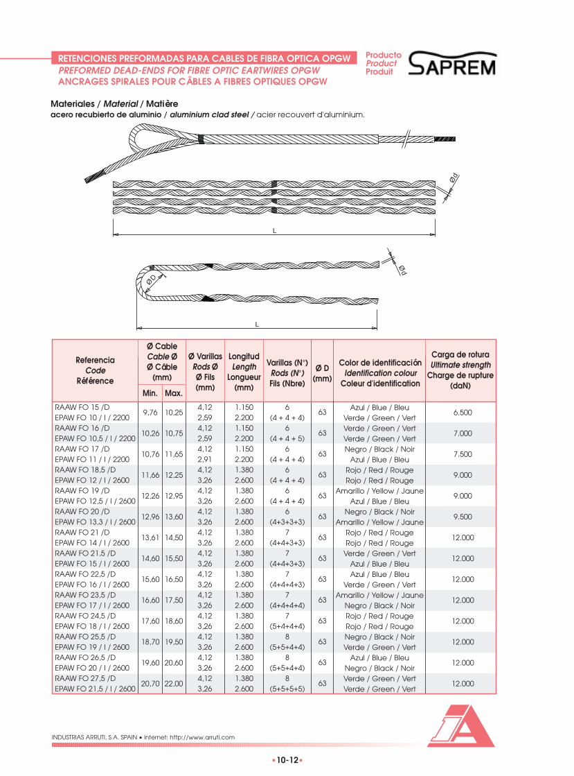
•10-12•
INDUSTRIAS ARRUTI, S.A. SPAIN • Internet: http://www.arruti.com
Materiales / Material / Matièreacero recubierto de aluminio / aluminium clad steel / acier recouvert d'aluminium.
L
L
ØD
Ød
Ød
9,76
10,26
10,76
11,66
12,26
12,96
13,61
14,60
15,60
16,60
17,60
18,70
19,60
20,70
10,25
10,75
11,65
12,25
12,95
13,60
14,50
15,50
16,50
17,50
18,60
19,50
20,60
22,00
4,122,594,122,594,122,914,123,264,123,264,123,264,123,264,123,264,123,264,123,264,123,264,123,264,123,264,123,26
1.1502.2001.1502.2001.1502.2001.3802.6001.3802.6001.3802.6001.3802.6001.3802.6001.3802.6001.3802.6001.3802.6001.3802.6001.3802.6001.3802.600
6(4 + 4 + 4)
6(4 + 4 + 5)
6(4 + 4 + 4)
6(4 + 4 + 4)
6(4 + 4 + 4)
6(4+3+3+3)
7(4+4+3+3)
7(4+4+3+3)
7(4+4+4+3)
7(4+4+4+4)
7(5+4+4+4)
8(5+5+4+4)
8(5+5+4+4)
8(5+5+5+5)
63
63
63
63
63
63
63
63
63
63
63
63
63
63
Azul / Blue / BleuVerde / Green / VertVerde / Green / VertVerde / Green / VertNegro / Black / Noir
Azul / Blue / BleuRojo / Red / RougeRojo / Red / Rouge
Amarillo / Yellow / JauneAzul / Blue / Bleu
Negro / Black / NoirAmarillo / Yellow / Jaune
Rojo / Red / RougeRojo / Red / Rouge
Verde / Green / VertAzul / Blue / BleuAzul / Blue / Bleu
Verde / Green / VertAmarillo / Yellow / Jaune
Negro / Black / NoirRojo / Red / RougeRojo / Red / RougeNegro / Black / NoirVerde / Green / Vert
Azul / Blue / BleuNegro / Black / NoirVerde / Green / VertVerde / Green / Vert
6.500
7.000
7.500
9.000
9.000
9.500
12.000
12.000
12.000
12.000
12.000
12.000
12.000
12.000
RAAW FO 15 /DEPAW FO 10 / I / 2200RAAW FO 16 /DEPAW FO 10,5 / I / 2200RAAW FO 17 /DEPAW FO 11 / I / 2200RAAW FO 18,5 /DEPAW FO 12 / I / 2600RAAW FO 19 /DEPAW FO 12,5 / I / 2600RAAW FO 20 /DEPAW FO 13,3 / I / 2600RAAW FO 21 /DEPAW FO 14 / I / 2600RAAW FO 21,5 /DEPAW FO 15 / I / 2600RAAW FO 22,5 /DEPAW FO 16 / I / 2600RAAW FO 23,5 /DEPAW FO 17 / I / 2600RAAW FO 24,5 /DEPAW FO 18 / I / 2600RAAW FO 25,5 /DEPAW FO 19 / I / 2600RAAW FO 26,5 /DEPAW FO 20 / I / 2600RAAW FO 27,5 /DEPAW FO 21,5 / I / 2600
ReferenciaCode
Référence
Color de identificaciónIdentification colour
Coleur d'identification
Carga de roturaUltimate strength
Charge de rupture(daN)
Min. Max.
Varillas (N°)Rods (N°)Fils (Nbre)
LongitudLength
Longueur(mm)
Ø VarillasRods ØØ Fils(mm)
Ø CableCable ØØ Câble
(mm)Ø D
(mm)
RETENCIONES PREFORMADAS PARA CABLES DE FIBRA OPTICA OPGWPREFORMED DEAD-ENDS FOR FIBRE OPTIC EARTWIRES OPGWANCRAGES SPIRALES POUR CÂBLES A FIBRES OPTIQUES OPGW
ProductoProductProduit

•10-13•
INDUSTRIAS ARRUTI, S.A. SPAIN • Internet: http://www.arruti.com
L
L
ØD
Ød
Ød
RETENCIONES PREFORMADAS PARA CABLES DE FIBRA OPTICA AUTOSOPORTADOSPREFORMED DEAD-ENDS FOR ADSS FIBRE OPTIC CABLESANCRAGES SPIRALES POUR CÂBLE SUPPORTE A FIBRES OPTIQUES
12,70
13,40
14,40
15,50
16,50
17,50
18,50
19,80
13,20
14,20
15,30
16,30
17,30
18,30
19,60
21,00
4,123,454,123,454,123,454,123,714,123,714,123,714,123,714,123,71
1.3802.5001.3802.5001.3802.5001.3802.5001.3802.5001.3802.5001.3802.5001.3802.500
7(4 + 4 + 4)
7(4+3+3+3)
7(4+4+3+3)
7(4+4+3+3)
7(4+4+4+3)
7(4+4+4+3)
7(4+4+4+4)
8(5+4+4+4)
63
63
63
63
63
63
63
63
Negro / Black / NoirAmarillo / Yellow / Jaune
Rojo / Red / RougeRojo / Red / Rouge
Verde / Green / VertAzul / Blue / Bleu
Amarillo / Yellow / JauneVerde / Green / VertRojo / Red / RougeNegro / Black / NoirNegro / Black / NoirRojo / Red / Rouge
Azul / Blue / BleuAmarillo / Yellow / Jaune
Negro / Black / NoirNegro / Black / Noir
10.000
12.000
12.500
13.000
13.500
13.500
13.500
15.000
RAAW FO 20 /DEPAL FO 13 / I / 2500RAAW FO 21 /DEPAL FO 13,6 / I / 2500RAAW FO 21,5 /DEPAL FO 14,6 / I / 2500RAAW FO 23,5 /DEPAL FO 16 / I / 2500RAAW FO 24,5 /DEPAL FO 17 / I / 2500RAAW FO 25,5 /DEPAL FO 18 / I / 2500RAAW FO 26,5 /DEPAL FO 19 / I / 2500RAAW FO 28 /DEPAL FO 20,5 / I / 25000
ReferenciaCode
Référence
Color de identificaciónIdentification colour
Coleur d'identification
Carga de roturaUltimate strength
Charge de rupture(daN)
Min. Max.
Varillas (N°)Rods (N°)Fils (Nbre)
LongitudLength
Longueur(mm)
Ø VarillasRods ØØ Fils(mm)
Ø CableCable ØØ Câble
(mm)Ø D
(mm)
En esta tabla se muestran las medidas para vanos mayores de 200 m. Para vanos inferiores se consultarán las medidasal Departamento Técnico de Industrias Arruti.This table shows the standard accessories for a span length higher than 200 m. For smaller span length, consult to Arruti’sTechnical Department.A cette table on montre las mesures pour portées supérieures a 200 m. Pour portées plus petites on consultera lasmesures au Département Technique de Industrias Arruti.
Materiales / Material / MatièreRetención: acero recubierto de aluminio. Empalme de protección: aleación de aluminio.Dead end: aluminium clad steel. Protection splice: aluminium alloy.Ancrage : acier recouvert d’aluminium. Jonction de protection : alliage d’aluminium.
ProductoProductProduit

•10-14•
INDUSTRIAS ARRUTI, S.A. SPAIN • Internet: http://www.arruti.com
Utilización / Usage / UtilisationEste tipo de soporte se emplea para fijar el cable y facilitar su bajada por la estructura, evitando la concentraciónde esfuerzos. Según el tipo de grapa, pueden acomodar uno o más cables.These clamps are intended for the securing and managing of fibre optic cables within the structure, avoiding stressconcentrations in the cable. Depending on the type of clamp used, they can accommodate single or multiple cables.Ces pinces sont employées pour fixer et faciliter l’installation des câbles sur la hauteur d’un pylône, et éviter desdommages sous les concentrations de contraintes. Selon le type de pince a utiliser, on peut placer un ou plus câbles.
Materiales / Material / MatièreCuerpo: acero forjado galvanizado en caliente. Grapa: aleación de aluminio. Tornillería: acero inoxidable y acerogalvanizado.Body: forged steel, hot dip galvanised. Clamp: aluminium alloy. Bolts and nuts: stainless steel and galvanised steel.Corps: acier forge, galvanisé à chaud. Pince : alliage d’aluminium. Boulons et écrous: acier inoxydable et aciergalvanisé.
90°
Par de aprieteTightenng Torque
Couple de Serrage(3 kg.m)
Par de aprieteTightenng Torque
Couple de Serrage(2 kg.m)
Instalación a 90°90° Alternative positon
Installation a 90°
SOPORTES DE BAJADA PARA CABLES DE FIBRA OPTICADOWNLEAD CLAMPS FOR FIBRE OPTIC CABLESPINCES DE DESCENTE POUR CÂBLES A FIBRES OPTIQUES

•10-15•
INDUSTRIAS ARRUTI, S.A. SPAIN • Internet: http://www.arruti.com
SOPORTES DE BAJADA PARA CABLES DE FIBRA OPTICADOWNLEAD CLAMPS FOR FIBRE OPTIC CABLESPINCES DE DESCENTE POUR CÂBLES A FIBRES OPTIQUES
120
40
45
70
M12
M12
Min 26
120
40
45
70
M12
M12
Min 26
ReferenciaCode
RéférenceMin. Max.
PesoWeightPoids(kg)
Ø Cable
SFO-CD-3 12 24 0,650
ReferenciaCode
RéférenceMin. Max.
PesoWeightPoids(kg)
Ø Cable
SFO-CD-3 12 24 0,750

•10-16•
INDUSTRIAS ARRUTI, S.A. SPAIN • Internet: http://www.arruti.com
SOPORTES DE BAJADA PARA CABLES DE FIBRA OPTICADOWNLEAD CLAMPS FOR FIBRE OPTIC CABLESPINCES DE DESCENTE POUR CÂBLES A FIBRES OPTIQUES
120
40
45
70
M12
M12
Min 26
120
40
45
70
M12
M12
10
Min 26
SFO-CS-3 / 8-14 8 14 0,750SFO-CS-3 / 14-18 14 18 0,750SFO-CS-3 / 18-24 18 24 0,850
ReferenciaCode
RéférenceMin. Max.
PesoWeightPoids(kg)
Ø Cable
SFO-CSD-3 / 8-14 8 14 0,900SFO-CSD-3 / 14-18 14 18 0,900SFO-CSD-3 / 18-24 18 24 1,200
ReferenciaCode
RéférenceMin. Max.
PesoWeightPoids(kg)
Ø Cable

•10-17•
INDUSTRIAS ARRUTI, S.A. SPAIN • Internet: http://www.arruti.com
SOPORTES DE BAJADA PARA CABLES DE FIBRA OPTICADOWNLEAD CLAMPS FOR FIBRE OPTIC CABLESPINCES DE DESCENTE POUR CÂBLES A FIBRES OPTIQUES
ReferenciaCode
RéférenceMin. Max.
PesoWeightPoids(kg)
Ø Cable
SFO-CD-3 / Ø 8 24 0,900
40
M12
M12
Min 26
45
7017
0
Se añadirá el diámetro Ø del cable al final de la referencia.Diameter of cable (Ø) must be added to code as a suffix.Ajouter le diamètre du câble (Ø) à la fin de la référence.

•10-18•
INDUSTRIAS ARRUTI, S.A. SPAIN • Internet: http://www.arruti.com
AMORTIGUADORES TIPO STOCKBRIDGE PARA CABLE OPGWSTOCKBRIDGE VIBRATION DAMPERS FOR OPGW CABLEAMORTISSEURS TYPE STOCKBRIDGE POUR CÂBLE OPGW
ProductoProductProduit
Materiales / Material / MatièreGrapa: aleación de aluminio. Contrapesos: acero forjado galvanizado en caliente. Cable portor: acero galvanizadoen caliente Tornillería: acero galvanizado en caliente ó acero inoxidable.Clamp: aluminium alloy. Counterweights: forged steel, hot dip galvanised. Messenger cable: hot dip galvanised steel.Bolts and nuts: hot dip galvanised steel or stainless steel.Mâchoire: alliage d’aluminium. Contrepoids : acier forge galvanisée à chaud. Câble : acier galvanisé. Boulons et écrous:acier galvanise a chaud ou acier inoxydable.
ReferenciaCode
RéférenceContrapesos
CounterweightsContrepoids
AmortiguadorDamper
AmortisseurMin. Max.
1 2
PesoWeightPoids
Ø Cable(mm) mm
A B
Par de aprieteTightening Torque
Couple de Serrage(kg.m)
TornilloBolt
Boulon
TamañoSize
Dimension
AMG-050913 8 13 53 55 M-10 4 0,500 0,900 1,800AMG-050920 13 20 55 63 M-10 3 0,500 0,900 1,800AMG-091520 13 20 55 63 M-10 3 0,900 1,500 3,000AMG-091526 18,5 26 58 74 M-12 2,5 0,900 1,500 3,000AMG-152426 18,5 26 58 74 M-12 2,5 1,500 2,400 4,500AMG-091532 23 32 63 85 M-12 2,5 0,900 1,500 3,000AMG-152432 23 32 63 85 M-12 2,5 1,500 2,400 4,500AMG-243532 23 32 63 85 M-12 2,5 2,400 3,500 6,400AMG-243544 32 44 73 100 M-14 2,5 2,400 3,500 6,500
A
B
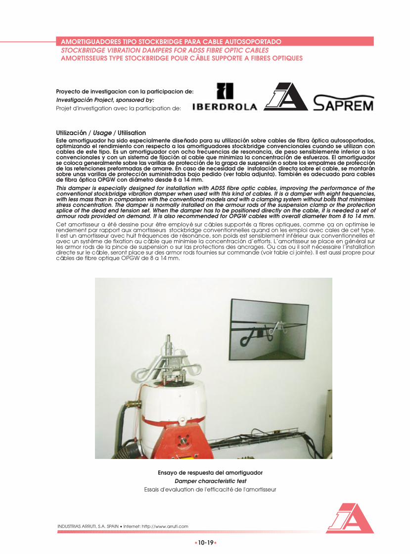
•10-19•
INDUSTRIAS ARRUTI, S.A. SPAIN • Internet: http://www.arruti.com
AMORTIGUADORES TIPO STOCKBRIDGE PARA CABLE AUTOSOPORTADOSTOCKBRIDGE VIBRATION DAMPERS FOR ADSS FIBRE OPTIC CABLESAMORTISSEURS TYPE STOCKBRIDGE POUR CÂBLE SUPPORTE A FIBRES OPTIQUES
Utilización / Usage / UtilisationEste amortiguador ha sido especialmente diseñado para su utilización sobre cables de fibra óptica autosoportados,optimizando el rendimiento con respecto a los amortiguadores stockbridge convencionales cuando se utilizan concables de este tipo. Es un amortiguador con ocho frecuencias de resonancia, de peso sensiblemente inferior a losconvencionales y con un sistema de fijación al cable que minimiza la concentración de esfuerzos. El amortiguadorse coloca generalmente sobre las varillas de protección de la grapa de suspensión o sobre los empalmes de protecciónde las retenciones preformadas de amarre. En caso de necesidad de instalación directa sobre el cable, se montaránsobre unas varillas de protección suministradas bajo pedido (ver tabla adjunta). También es adecuado para cablesde fibra óptica OPGW con diámetro desde 8 a 14 mm.This damper is especially designed for installation with ADSS fibre optic cables, improving the performance of theconventional stockbridge vibration damper when used with this kind of cables. It is a damper with eight frequencies,with less mass than in comparison with the conventional models and with a clamping system without bolts that minimisesstress concentration. The damper is normally installed on the armour rods of the suspension clamp or the protectionsplice of the dead end tension set. When the damper has to be positioned directly on the cable, it is needed a set ofarmour rods provided on demand. It is also recommended for OPGW cables with overall diameter from 8 to 14 mm.Cet amortisseur a été dessine pour être employé sur câbles supportés a fibres optiques, comme ça on optimise lerendement par rapport aux amortisseurs stockbridge conventionnelles quand on les emploi avec cales de cet type.Il est un amortisseur avec huit fréquences de résonance, son poids est sensiblement inférieur aux conventionnelles etavec un système de fixation au câble que minimise la concentración d’efforts. L’amortisseur se place en général surles armor rods de la pince de suspension o sur las protections des ancrages. Ou cas ou il soit nécessaire l’installationdirecte sur le câble, seront place sur des armor rods fournies sur commande (voir table ci jointe). Il est aussi propre pourcâbles de fibre optique OPGW de 8 a 14 mm.
Proyecto de investigacion con la participacion de:Investigación Project, sponsored by:Projet d'investigation avec la participation de:
Ensayo de respuesta del amortiguadorDamper characteristic test
Essais d'evaluation de l'efficacité de l'amortisseur

•10-20•
INDUSTRIAS ARRUTI, S.A. SPAIN • Internet: http://www.arruti.com
AMORTIGUADORES TIPO STOCKBRIDGE PARA CABLE AUTOSOPORTADOSTOCKBRIDGE VIBRATION DAMPERS FOR ADSS FIBRE OPTIC CABLESAMORTISSEURS TYPE STOCKBRIDGE POUR CÂBLE SUPPORTE A FIBRES OPTIQUES
450
320
65
ØD
ød
Materiales / Material / MatièreGrapa: aleación de aluminio. Contrapesos: acero forjado galvanizado en caliente. Cable portor: acero galvanizadoen caliente. Varillas de fijación: acero recubierto de aluminio. Varillas de protección: aleación de aluminio.Clamp: aluminium alloy. Counterweights: forged steel, hot dip galvanised. Messenger cable: hot dip galvanised steel.Fixation rods: aluminium clad steel. Preformed armour rods: aluminium alloy.Mâchoire: alliage d’aluminium. Contrepoids : acier forge galvanisée à chaud. Câble : acier galvanisé. Fils de fixation :acier recouvert d’aluminium. Armor rods : alliage d’aluminium.
ReferenciaCode
Référence
Varillas de protecciónAmour rodsArmor rods
Min. Max.
RangoRangeRang
ØD (mm)
PesoWeightpoids(kg)
AMORFO-160-170 16 17 VSAMAW-160-170 1,000 VPAMAL-100-110 10 11AMORFO-170-180 17 18 VSAMAW-170-180 1,000 VPAMAL-110-120 11 12AMORFO-180-190 18 19 VSAMAW-180-190 1,000 VPAMAL-120-130 12 13AMORFO-190-200 19 20 VSAMAW-190-200 1,000 VPAMAL-130-140 13 14AMORFO-200-210 20 21 VSAMAW-200-210 1,000 VPAMAL-140-150 14 15AMORFO-210-220 21 22 VSAMAW-210-220 1,000 VPAMAL-150-160 15 16AMORFO-220-230 22 23 VSAMAW-220-230 1,000 VPAMAL-160-170 16 17AMORFO-230-240 23 24 VSAMAW-230-240 1,000 VPAMAL-170-180 17 18AMORFO-240-250 24 25 VSAMAW-240-250 1,000 VPAMAL-180-190 18 19AMORFO-250-260 25 26 VSAMAW-250-260 1,000 VPAMAL-190-200 19 20AMORFO-260-270 26 27 VSAMAW-260-270 1,000 VPAMAL-200-210 20 21AMORFO-270-280 27 28 VSAMAW-270-280 1,000 VPAMAL-210-220 21 22
Min. Max.
Varillas de fijaciónFixation rods
Fils de fixation
RangoRangeRang
ød (mm)

POLEAS DE TENDIDO Y RODILLOS
POULIES DE POSE DE CABLES ETROLEAUX SOUTERRAINS
STRINGING BLOCKS ANDUNDERGROUND ROLLERS

INTRODUCCIONINTRODUCTION / INTRODUCTION
INDUSTRIAS ARRUTI, S.A. SPAIN • Internet: http://www.arruti.com
•11-1•
Las poleas y rodillos para el tendido de conductores, están fabricados de aluminio fundido en coquilla con aleacionesde primera fusión, aunando las características de gran calidad y gran resistencia con el mínimo precio.Las poleas se montan sobre rodamientos en los soportes. Los soportes se fabrican basándose en componentes deacero galvanizado, siendo de gran ligereza y fácil extracción del cable.A la hora de seleccionar la polea de tendido adecuada al conductor a tender, se deberá tener en cuenta que eldiámetro en el fondo de la garganta debe ser superior a 20 veces el diámetro del conductor.Estos elementos pueden ser suministrados como un conjunto o separados, es decir, por una parte la polea ó rodilloy por otra el soporte.Las poleas de la serie P cumplen con las más variadas funciones, siendo especialmente recomendadas los modelosP-140 y P-360 para el tendido de cables de tierra por su gran robustez. Bajo pedido, podrán suministrarse con sugarganta recubierta de neopreno.Las poleas de la serie PR son poleas radiales de gran ligereza y van provistas de engrasadores para la lubricaciónde los rodamientos. Este tipo de poleas puede montarse con soporte sencillo o soporte triple para el tendido de variosconductores (ver figura). Las poleas de la serie PR llevan las gargantas recubiertas de neopreno.Los rodillos se utilizan para el tendido de cables subterráneos y junto con los soportes han sido diseñados para podertender con gran sencillez y comodidad, evitando el deterioro de los conductores. Se dispone de conjuntos de rodillospara tramos rectos y para vencer ángulos.
Stringing blocks and underground rollers are manufactured of high quality chill cast aluminium alloy, linking qualityand high resistance features to a minimum weight.Sheaves are mounted on bearings into the frame. These frames are manufactured with components made of galvanisedsteel, being extremely light and permitting easy extraction of conductor.The selection of the necessary sheave size must be done taking into account that the diameter of the sheave into thegorges has to be at least 20 times the conductor diameter.These accessories can be supplied assembled or as spare parts (sheaves and frames).With P series stringing blocks can be performed many different functions. P-140 and P-360 models are highlyrecommended for the stringing of earthwires, due to their high ruggedness. They can be supplied with neoprene linedgorges under request.PR Stringing block series are made with extremely light radial sheaves with nipples for bearing lubrication. These kingof sheaves can be mounted in a single or triple frame (see figure) for the stringing of several conductors. PR Stringingblocks are supplied with neoprene lined gorges.Underground rollers are intended for stringing underground conductors, and in conjunction with the appropriate framethey are designed for an easy and quick operation, avoiding conductor damages. There are two different undergroundroller assemblies: straight and angle type.
Les poulies et rouleaux pour le tirage de conducteurs sont fabriqués en aluminium moulé en coquille avec alliagesde première fusion de grande résistance et qualité.Les poulies se montent sur des roulements aux cadres. On fabrique les cadres en acier galvanise très léger et facilede les enlever du conducteur.A l’heure de sélectionner la poulie plus appropriée pour le conducteur qu’on va tirer, on devra tenir sur compte quele diamètre au fond de la gorge doit être supérieur á 20 fois le diamètre du conducteur.Ces éléments peuvent être fournis en conjoint ou séparés, c’est à dire, d’une part la poulie ou roulement et d’autrepartie le cadre.Les poulies de la série P accomplissent les plus variées fonctions, les modelés P-140 et P-360 ont été étudiés spécialementpour le tirage des câbles de garde étant donné sa dureté. Sur commande on peut les fournir avec gorge garnieen néoprène.Les poulies de la série PR sont de type radial très léger avec graisseur pour la lubrification des roulements. On peutmonter ce type de poulies avec cadre simple ou triple pour le tirage de plusieurs conducteurs (voir figure). Les pouliesde la série PR ont la gorge recouverte en Néoprène.Les roulements sont utilisés pour le tirage des câbles souterrains et avec les cadres ont été dessinés pour pouvoir fairele déroulage facile et commode et éviter endommager les conducteurs. On fabrique des conjoints de roulementspour zones droites et surmonter les angles.
Conjunto de poleas triple.Triple sheave assembly.Conjoint de poulies triples.

POLEAS SERIE PP SERIES STRINGING BLOCKS / POULIES SERIE P
•11-2•
INDUSTRIAS ARRUTI, S.A. SPAIN • Internet: http://www.arruti.com
L
Ø D
Ø C
A
B
E
ReferenciaCode
Référence
mm.
D LACP-140 3 P-140 1 SP-140 2 42 30 90 140 R13 142CP-140-RT 4 P-140-RT 1,5 SP-140-RT 2,5 85 62 48 140 R28 165
PesoWeightPoids(Kg)
PoleaSheavePoulie
PesoWeightPoids(Kg)
SoporteFrameCadre
PesoWeightPoids(Kg) B C E
225
Ø 1
60
Ø 252
58
70
R 20
ReferenciaCode
Référence
CP-252 5,25 P-252 2,75 SP-252 2,5
PesoWeightPoids(Kg)
PoleaSheavePoulie
PesoWeightPoids(Kg)
SoporteFrameCadre
PesoWeightPoids(Kg)

POLEAS SERIE PP SERIES STRINGING BLOCKS / POULIES SERIE P
•11-3•
INDUSTRIAS ARRUTI, S.A. SPAIN • Internet: http://www.arruti.com
225
Ø 300
Ø 2
18
46
60
R 22
ReferenciaCode
Référence
CP-300 5,5 P-300 3 SP-300 2,5
PesoWeightPoids(Kg)
PoleaSheavePoulie
PesoWeightPoids(Kg)
SoporteFrameCadre
PesoWeightPoids(Kg)
280
Ø 2
58
Ø 360
70
85
R 29
ReferenciaCode
Référence
CP-360 10 P-360 7 SP-360 3
PesoWeightPoids(Kg)
PoleaSheavePoulie
PesoWeightPoids(Kg)
SoporteFrameCadre
PesoWeightPoids(Kg)

POLEAS SERIE PP SERIES STRINGING BLOCKS / POULIES SERIE P
•11-4•
INDUSTRIAS ARRUTI, S.A. SPAIN • Internet: http://www.arruti.com
Ø 3
88
350
R 27,5
55
67 Ø 480
ReferenciaCode
Référence
CP-480 11,5 P-480 8 SP-480 3,5
PesoWeightPoids(Kg)
PoleaSheavePoulie
PesoWeightPoids(Kg)
SoporteFrameCadre
PesoWeightPoids(Kg)
R 23
52
67
350
Ø 540
Ø 4
65
ReferenciaCode
Référence
CP-540 12,5 P-540 9 SP-540 3,5
PesoWeightPoids(Kg)
PoleaSheavePoulie
PesoWeightPoids(Kg)
SoporteFrameCadre
PesoWeightPoids(Kg)

POLEAS SERIE PRPR SERIES STRINGING BLOCKS / POULIES SERIES PR
•11-5•
INDUSTRIAS ARRUTI, S.A. SPAIN • Internet: http://www.arruti.com
ReferenciaCode
Référence
CPR-540 14,5 PR-540 9 SPR-540 5,5
PesoWeightPoids(Kg)
PoleaSheavePoulie
PesoWeightPoids(Kg)
SoporteFrameCadre
PesoWeightPoids(Kg)
52
67
426
Ø 540
Ø 4
65
R 23
65
85
Ø 8
00
595
Ø 880
ReferenciaCode
Référence
CPR-880 31 PR-880 24 SPR-880 7
PesoWeightPoids(Kg)
PoleaSheavePoulie
PesoWeightPoids(Kg)
SoporteFrameCadre
PesoWeightPoids(Kg)

RODILLOS SUBTERRANEOSUNDERGROUNG ROLLERS / RELEAUX SOUTERRAINS
•11-6•
INDUSTRIAS ARRUTI, S.A. SPAIN • Internet: http://www.arruti.com
124
Ø12
8
Ø44
RodilloRoller
Rouleaux
EL-1 0,5 SPS-1 7 370 270 120 7,5
SoporteFrameCadre
PesoWeightPoids(Kg)
LongitudLength
Longueur
PesoWeightPoids(Kg)
PesoWeightPoids(Kg)
AnchuraWidth
Largueur
AlturaHeight
Hauteur
mm
RodilloRoller
Rouleaux
EL-1 0,5 SPS-2 8 370 270 220 9
SoporteFrameCadre
PesoWeightPoids(Kg)
LongitudLength
Longueur
PesoWeightPoids(Kg)
PesoWeightPoids(Kg)
AnchuraWidth
Largueur
AlturaHeight
Hauteur
mm

RODILLOS SUBTERRANEOSUNDERGROUNG ROLLERS/ ROLEAUX SOUTERRAINS
•11-7•
INDUSTRIAS ARRUTI, S.A. SPAIN • Internet: http://www.arruti.com
195
Ø18
0
Ø68
RodilloRoller
Rouleaux
EL-3 4 SPS-3 5 310 290 300 9
SoporteFrameCadre
PesoWeightPoids(Kg)
LongitudLength
Longueur
PesoWeightPoids(Kg)
PesoWeightPoids(Kg)
AnchuraWidth
Largueur
AlturaHeight
Hauteur
mm
RodilloRoller
Rouleaux
EL-3 4 SPS-3/3 9,5 630 350 345 21,5
SoporteFrameCadre
PesoWeightPoids(Kg)
LongitudLength
Longueur
PesoWeightPoids(Kg)
PesoWeightPoids(Kg)
AnchuraWidth
Largueur
AlturaHeight
Hauteur
mm

Barrio Ugarte, s/n
48392 MUGICA (VIZCAYA) SPAIN
Internet: http://www.arruti.com
INDUSTRIAS ARRUTI, S.A.
Tel. +34-94-625 20 02Fax +34-94-625 54 91
E-Mail: [email protected]
CERTIFICADONº 936062


