
Cellular Networks and Mobile Compu5ng COMS 6998-‐8, Spring 2012
Instructor: Li Erran Li ([email protected])
hKp://www.cs.columbia.edu/~coms6998-‐8/ 1/30/2012: Cellular Networks: UMTS and LTE
Outline • Wireless communica5ons basics
– Signal propaga5on, fading, interference, cellular principle
• Mul5-‐access techniques and cellular network air-‐interfaces – FDMA, TDMA, CDMA, OFDM
• 3G: UMTS – Architecture: en55es and protocols – Physical layer – RRC state machine
• 4G: LTE – Architecture: en55es and protocols – Physical layer – RRC state machine
Cellular Networks and Mobile Compu5ng (COMS 6998-‐8) 2 1/23/12

Cellular Networks and Mobile Compu5ng (COMS 6998-‐8)
Basic Wireless Communica5on
TransmiKer
Informa5on is embedded in electromagne5c radia5on
Receiver
Lossy signal and interference
Noise
Recover informa5on
3 1/23/12 Courtesy: Harish Vishwanath
Cellular Networks and Mobile Compu5ng (COMS 6998-‐8)
Noise & Interference
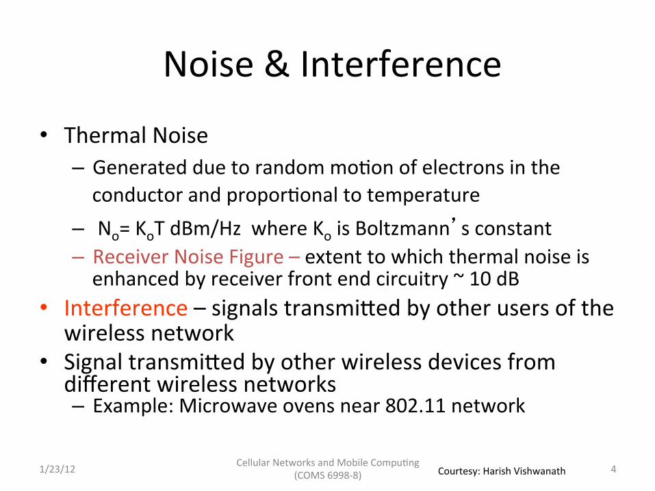
• Thermal Noise – Generated due to random mo5on of electrons in the conductor and propor5onal to temperature
– No= KoT dBm/Hz where Ko is Boltzmann’s constant – Receiver Noise Figure – extent to which thermal noise is enhanced by receiver front end circuitry ~ 10 dB
• Interference – signals transmiKed by other users of the wireless network
• Signal transmiKed by other wireless devices from different wireless networks – Example: Microwave ovens near 802.11 network
4 1/23/12 Courtesy: Harish Vishwanath

Cellular Networks and Mobile Compu5ng (COMS 6998-‐8)
Impact of White Gaussian Noise
-10 -5 0 5 10 15 20 25 30 0
1
2
3
4
5
6
7
8
9
10
SNR (dB)
Cap
acity
(bits
/sec
/Hz)
SNR = Signal Power
Noise Power
Shannon Capacity
C = log (1 + SNR)
5 1/23/12 Courtesy: Harish Vishwanath

Cellular Networks and Mobile Compu5ng (COMS 6998-‐8)
ScaKering of Signals -‐ Mul5path Fading
21( ) ( ) cj f ts t x t e π=
2 ( / )2 ( ) ( / ) cj f t d c js t x t d c e π φ−Δ += − Δ
Reflec5on Diffrac5on Absorp5on
Mul5ple paths with random phases and gains combine construc5vely and destruc5vely to cause significant amplitude varia5ons
6 1/23/12 Courtesy: Harish Vishwanath

Cellular Networks and Mobile Compu5ng (COMS 6998-‐8)
Impact of Mobility
v
21( ) ( ) cj f ts t x t e π=
2 cos( ) ( )
2 ( ) ( )cvj f t t j
s t a x t t eπ θ δ φ
λδ⎛ ⎞+ − +⎜ ⎟⎝ ⎠= −
θ
Doppler Shik =
cos( )vθ
λ
Signal Amplitude
5me
Mul5path Fading
7 1/23/12 Courtesy: Harish Vishwanath

Cellular Networks and Mobile Compu5ng (COMS 6998-‐8)
Flat & Frequency Selec5ve Fading • When the mul5path delay is small compared to symbol dura5on of the signal, fading is flat or frequency non-‐selec5ve
• Happens when signal bandwidth is small
• Urban macro-‐cell delay spread is 10 micro seconds • When signal bandwidth is large different bands have different gains – frequency selec5ve fading
max( ) ( )x t t x tδ− ≈
max
1xB tδ=
1 -‐1 -‐1
1 Symbol
8 1/23/12 Courtesy: Harish Vishwanath

Cellular Networks and Mobile Compu5ng (COMS 6998-‐8)
Typical Pathloss 1.0 10.0 100.0
-‐50
-‐70
-‐90
-‐110
Free space : -‐20 dB/decade
Urban Macro cell -‐40 dB/decade
Shadow fading Log-‐normal with std ~ 8 dB
A decade : transmiKer and receiver distance increase 10 5mes
9 1/23/12 Courtesy: Harish Vishwanath

Cellular Networks and Mobile Compu5ng (COMS 6998-‐8)
Spectrum Reuse
S a
I b
S b
I a
a and b can receive simultaneously on the same frequency band if SINRa and SINRb are above required threshold
This happens if the respec5ve transmiKers are sufficiently far apart
SINRa = S a
I a + N
A B
10 1/23/12 Courtesy: Harish Vishwanath

Cellular Networks and Mobile Compu5ng (COMS 6998-‐8)
The Cellular Principle • Base sta5ons transmit to and receive from mobiles at the assigned spectrum – Mul5ple base sta5ons use the same spectrum (spectral reuse)
• The service area of each base sta5on is called a cell
• The wireless network consists of large number of cells – Example – The network in Northern NJ is about 150 base sta5ons for a given operator
• Cells can be further divided into mul5ple sectors using sectorized antennas
• Each terminal is typically served by the “closest” base sta5on(s)
11 1/23/12 Courtesy: Harish Vishwanath
Cellular Networks and Mobile Compu5ng (COMS 6998-‐8)
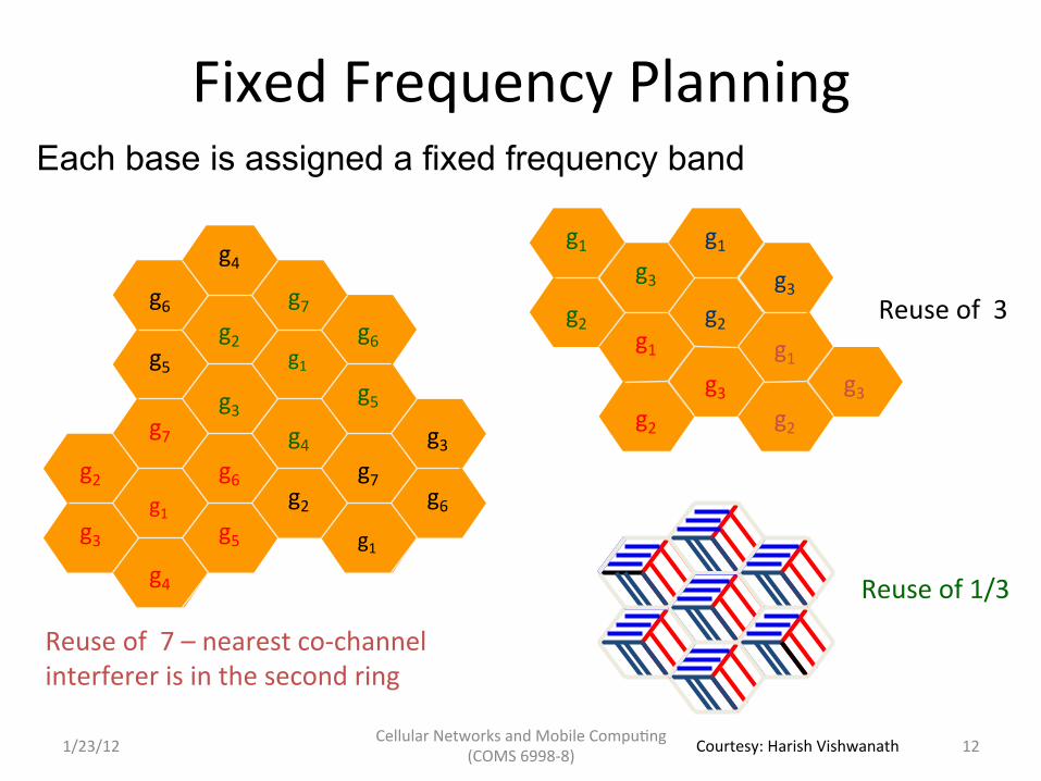
Fixed Frequency Planning Each base is assigned a fixed frequency band
Reuse of 7 – nearest co-‐channel interferer is in the second ring
Reuse of 3
g1
g2
g1
g2 g3
g1
g2 g3
g2 g3
g1
g3
g2
g7
g1 g6
g3
g4
g5
g6
g4
g2 g7
g5
g3
g1
g4
g5
g7 g3
g2
g1
g6
g6
Reuse of 1/3
12 1/23/12 Courtesy: Harish Vishwanath
Cellular Networks and Mobile Compu5ng (COMS 6998-‐8)
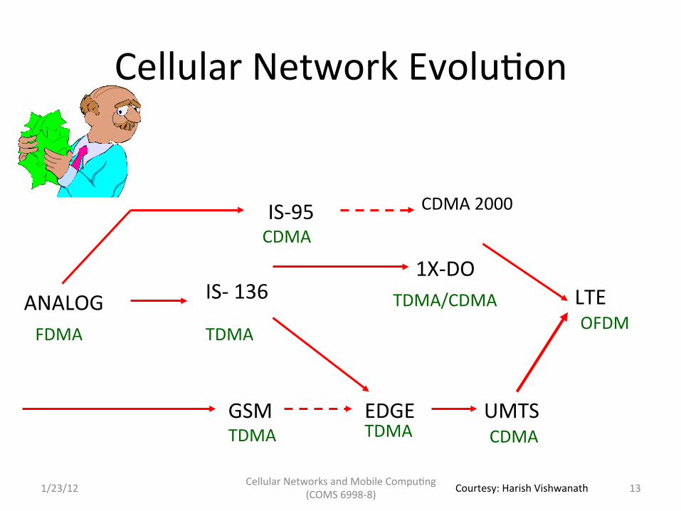
Cellular Network Evolu5on
IS-‐ 136
GSM TDMA
EDGE TDMA
UMTS CDMA
LTE ANALOG FDMA
IS-‐95
TDMA
CDMA
CDMA 2000
1X-‐DO TDMA/CDMA
OFDM
13 1/23/12 Courtesy: Harish Vishwanath
Cellular Networks and Mobile Compu5ng (COMS 6998-‐8)
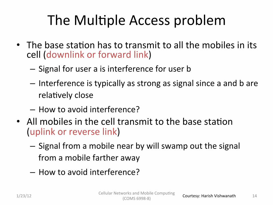
The Mul5ple Access problem • The base sta5on has to transmit to all the mobiles in its cell (downlink or forward link) – Signal for user a is interference for user b – Interference is typically as strong as signal since a and b are rela5vely close
– How to avoid interference? • All mobiles in the cell transmit to the base sta5on (uplink or reverse link) – Signal from a mobile near by will swamp out the signal from a mobile farther away
– How to avoid interference?
14 1/23/12 Courtesy: Harish Vishwanath
Cellular Networks and Mobile Compu5ng (COMS 6998-‐8)
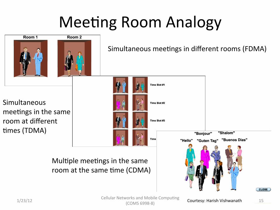
Mee5ng Room Analogy Simultaneous mee5ngs in different rooms (FDMA)
Simultaneous mee5ngs in the same room at different 5mes (TDMA)
Mul5ple mee5ngs in the same room at the same 5me (CDMA)
15 1/23/12 Courtesy: Harish Vishwanath
Cellular Networks and Mobile Compu5ng (COMS 6998-‐8)
Frequency Division Mul5ple Access
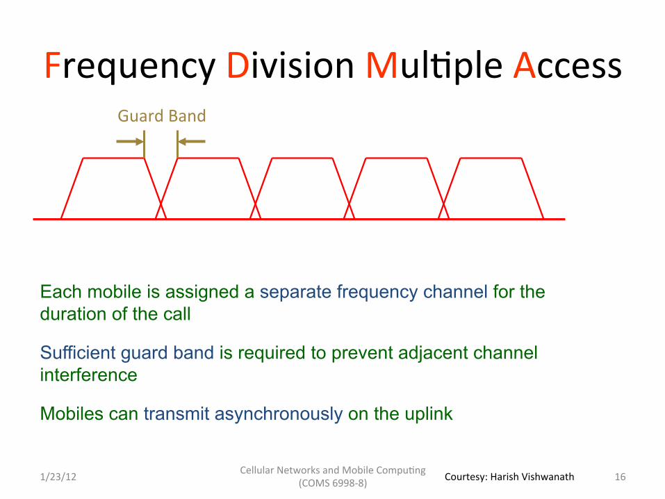
Each mobile is assigned a separate frequency channel for the duration of the call
Sufficient guard band is required to prevent adjacent channel interference
Mobiles can transmit asynchronously on the uplink
Guard Band
16 1/23/12 Courtesy: Harish Vishwanath

Cellular Networks and Mobile Compu5ng (COMS 6998-‐8)
Time Division Mul5ple Access Time is divided into slots and only one mobile transmits during each slot
FRAME j FRAME j + 1 FRAME j+2
SLOT 1 SLOT 2 SLOT 3 SLOT 4 SLOT 5 SLOT 6
Guard time – Signal transmitted by mobiles at different locations do not arrive at the base at the same time
17 1/23/12 Courtesy: Harish Vishwanath

Cellular Networks and Mobile Compu5ng (COMS 6998-‐8)
TDMA Characteris5cs
• Discon5nuous transmission with informa5on to be transmiKed buffered un5l transmission 5me – Possible only with digital technology – Transmission delay
• Synchronous transmission required – Mobiles derive 5ming from the base sta5on signal
• Guard 5me can be reduced if mobiles pre-‐correct for transmission delay – More efficient than FDMA which requires significant guard band
18 1/23/12 Courtesy: Harish Vishwanath
Cellular Networks and Mobile Compu5ng (COMS 6998-‐8)
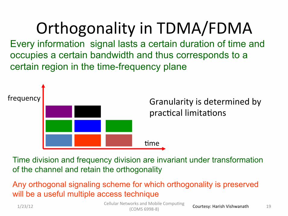
Orthogonality in TDMA/FDMA Every information signal lasts a certain duration of time and occupies a certain bandwidth and thus corresponds to a certain region in the time-frequency plane
Granularity is determined by prac5cal limita5ons
Time division and frequency division are invariant under transformation of the channel and retain the orthogonality
Any orthogonal signaling scheme for which orthogonality is preserved will be a useful multiple access technique
5me
frequency
19 1/23/12 Courtesy: Harish Vishwanath

Cellular Networks and Mobile Compu5ng (COMS 6998-‐8)
Code Division Mul5ple Access
• Use of orthogonal codes to separate different transmissions • Each symbol or bit is transmiKed as a larger number of bits using the user
specific code – Spreading • Spread spectrum technology
– The bandwidth occupied by the signal is much larger than the informa5on transmission rate
– Example: 9.6 Kbps voice is transmiKed over 1.25 MHz of bandwidth, a bandwidth expansion of ~100
20 1/23/12 Courtesy: Harish Vishwanath

Cellular Networks and Mobile Compu5ng (COMS 6998-‐8)
Spread Spectrum systems
frequency
5me
code
5me
Code orthogonality is preserved under linear transformations and hence near orthogonality is preserved under signal propagation
21 1/23/12 Courtesy: Harish Vishwanath

Cellular Networks and Mobile Compu5ng (COMS 6998-‐8)
Orthogonal Walsh Codes 1 1 1 1 1 -‐1 1 -‐1 1 1 -‐1 -‐1 1 -‐1 -‐1 1
Spread factor 4 Walsh Array
chip
TransmiKer Receiver Walsh Code
Informa5on Spreading De-‐spreading
∑bit
22 1/23/12 Courtesy: Harish Vishwanath
Cellular Networks and Mobile Compu5ng (COMS 6998-‐8)
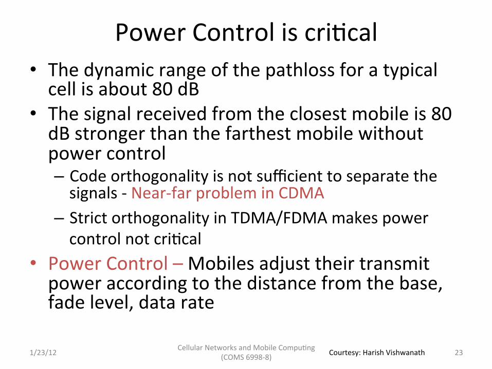
Power Control is cri5cal • The dynamic range of the pathloss for a typical cell is about 80 dB
• The signal received from the closest mobile is 80 dB stronger than the farthest mobile without power control – Code orthogonality is not sufficient to separate the signals -‐ Near-‐far problem in CDMA
– Strict orthogonality in TDMA/FDMA makes power control not cri5cal
• Power Control – Mobiles adjust their transmit power according to the distance from the base, fade level, data rate
23 1/23/12 Courtesy: Harish Vishwanath

Cellular Networks and Mobile Compu5ng (COMS 6998-‐8)
Why CDMA? • Simplified frequency planning
– Universal frequency reuse with spreading gain to mi5gate interference
– Interference averaging allows designing for average interference level instead of for worst case interference
TDMA / FDMA CDMA
24 1/23/12 Courtesy: Harish Vishwanath

Cellular Networks and Mobile Compu5ng (COMS 6998-‐8)
Why CDMA? • Variable rate Vocoder with Power Control
– Advanced data compression technology is used to compress data according to content
– Typical voice ac5vity is 55% -‐ CDMA reduces interference by turning down transmission between talk spurts
– Reduced average transmission power increases capacity through sta5s5cal mul5plexing
– Compensate for fading through power control -‐ transmit more power only under deep fades avoiding big fade margins
25 1/23/12 Courtesy: Harish Vishwanath

Cellular Networks and Mobile Compu5ng (COMS 6998-‐8)
Why CDMA?
• Simple mul5path combining to combat fading Each signal arriving at a different 5me can be recovered separately and combined coherently
The resul5ng diversity gain reduces fading
21( ) ( ) cj f ts t x t e π=
2 ( )2 ( ) ( ) c cj f t T j
cs t x t T e π φ− += − Spreading sequence in is offset by one chip compared to spreading sequence in
( )x t
( )cx t T−
26 1/23/12 Courtesy: Harish Vishwanath

Cellular Networks and Mobile Compu5ng (COMS 6998-‐8)
Why CDMA?
• Sok Handoff -‐ Make-‐before-‐break handoff
Mobile can transmit and receive from multiple base stations because all base stations use the same frequency
Signals from different bases can be received separately and then combined because each base uses a unique spreading code
27 1/23/12 Courtesy: Harish Vishwanath

What is OFDM ?
OFDM invented in Bell Labs by R.W. Chang in ~1964 and patent awarded in 1970
Widely used: Digital audio and Video broadcasting, ADSL, HDSL, Wireless LANs
Orthogonal Frequency Division Multiplexing is block transmission of N symbols in parallel on N orthogonal sub-carriers
Guard Band
Traditional Multi-carrier
Frequency
1 T
Frequency
OFDM
Implemented digitally through FFTs
Cellular Networks and Mobile Compu5ng (COMS 6998-‐8) 1/23/12 28 Courtesy: Harish Vishwanath
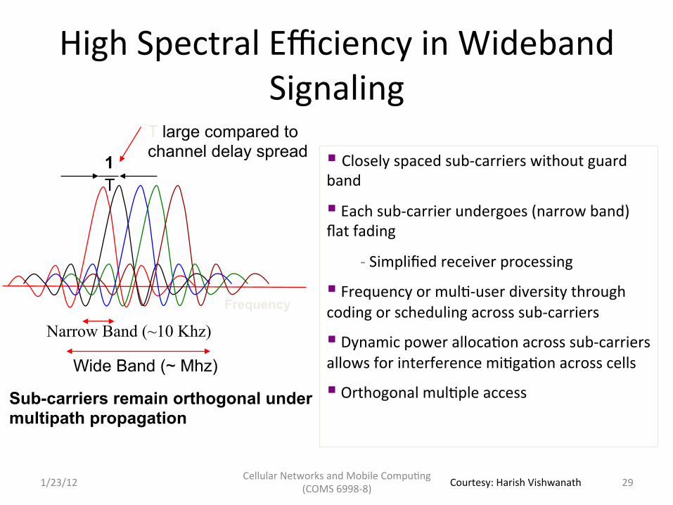
High Spectral Efficiency in Wideband Signaling
§ Closely spaced sub-‐carriers without guard band
§ Each sub-‐carrier undergoes (narrow band) flat fading
-‐ Simplified receiver processing
§ Frequency or mul5-‐user diversity through coding or scheduling across sub-‐carriers
§ Dynamic power alloca5on across sub-‐carriers allows for interference mi5ga5on across cells
§ Orthogonal mul5ple access
Frequency
Narrow Band (~10 Khz)
Wide Band (~ Mhz)
T large compared to channel delay spread
Sub-carriers remain orthogonal under multipath propagation
T 1
Cellular Networks and Mobile Compu5ng (COMS 6998-‐8) 29 1/23/12 Courtesy: Harish Vishwanath
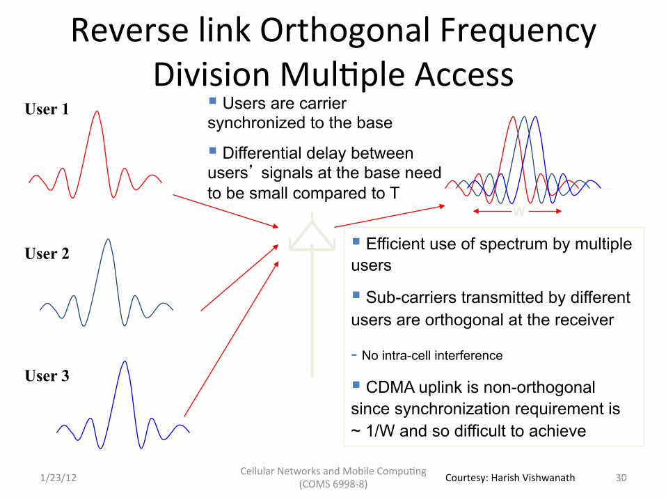
Reverse link Orthogonal Frequency Division Mul5ple Access
User 1
User 2
User 3
§ Efficient use of spectrum by multiple users
§ Sub-carriers transmitted by different users are orthogonal at the receiver
- No intra-cell interference
§ CDMA uplink is non-orthogonal since synchronization requirement is ~ 1/W and so difficult to achieve
§ Users are carrier synchronized to the base
§ Differential delay between users’ signals at the base need to be small compared to T
W
Cellular Networks and Mobile Compu5ng (COMS 6998-‐8) 1/23/12 30 Courtesy: Harish Vishwanath
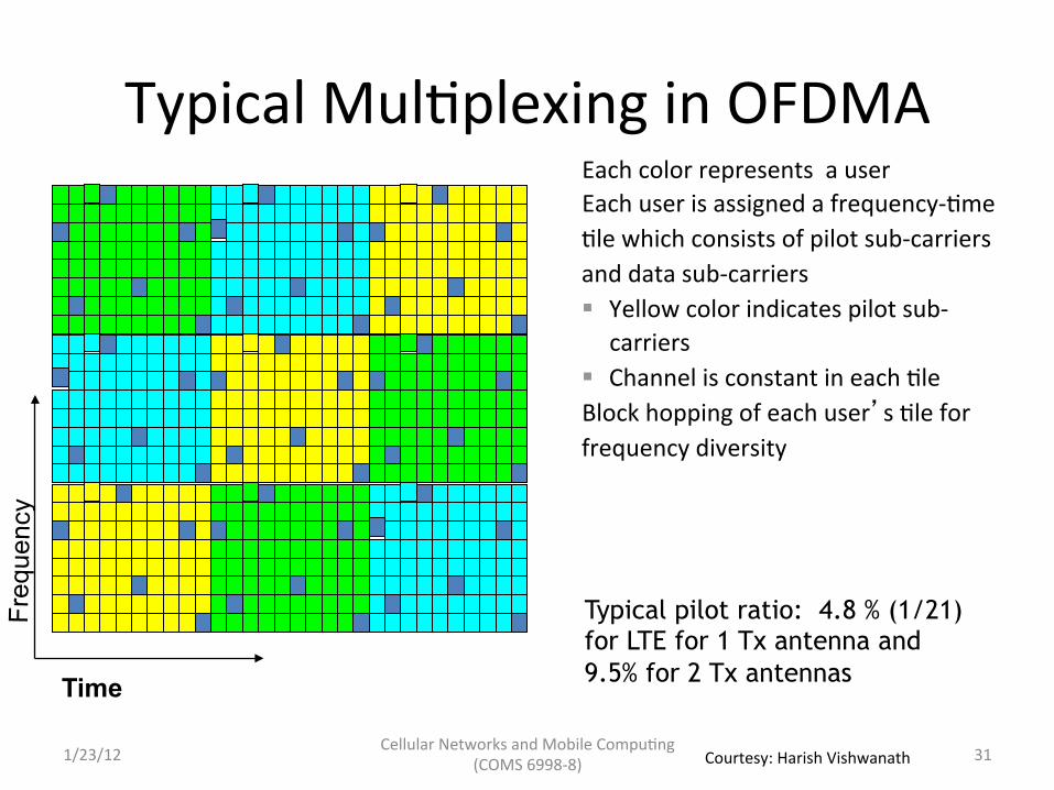
Typical Mul5plexing in OFDMA Each color represents a user Each user is assigned a frequency-‐5me 5le which consists of pilot sub-‐carriers and data sub-‐carriers § Yellow color indicates pilot sub-‐
carriers § Channel is constant in each 5le
Block hopping of each user’s 5le for frequency diversity
Time
Freq
uenc
y
Typical pilot ratio: 4.8 % (1/21) for LTE for 1 Tx antenna and 9.5% for 2 Tx antennas
Cellular Networks and Mobile Compu5ng (COMS 6998-‐8) 1/23/12 31 Courtesy: Harish Vishwanath

Outline • Wireless communica5ons basics
– Signal propaga5on, fading, interference, cellular principle
• Mul5-‐access techniques and cellular network air-‐interfaces – FDMA, TDMA, CDMA, OFDM
• 3G: UMTS – Architecture: en55es and protocols – Physical layer – RRC state machine
• 4G: LTE – Architecture: en55es and protocols – Physical layer – RRC state machine
Cellular Networks and Mobile Compu5ng (COMS 6998-‐8) 32 1/23/12

33
UMTS System Architecture
USIM
ME
Node B
Node B RNC
Node B
Node B RNC
MSC/ VLR GMSC
SGSN GGSN
HLR
UTRAN CN UE
External Networks
Cu
Uu Iu
Iub Iur
Cellular Networks and Mobile Compu5ng (COMS 6998-‐8) 1/23/12
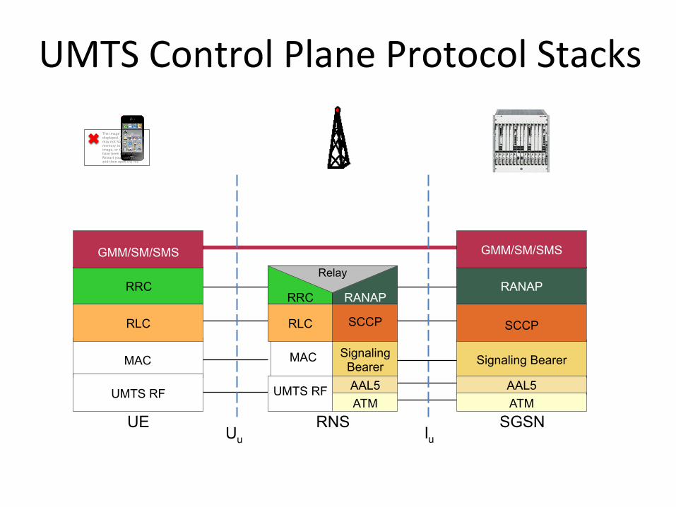
UMTS Control Plane Protocol Stacks
I u U u SGSN
Signaling Bearer SCCP
RANAP
GMM/SM/SMS
AAL5 ATM
UE UMTS RF
MAC
RLC
RRC GMM/SM/SMS
RNS
RRC
Signaling Bearer
The image cannot be displayed. Your computer may not have enough memory to open the image, or the image may have been corrupted. Restart your computer, and then open the file
MAC AAL5 ATM
SCCP RANAP
Relay
UMTS RF
RLC

UMTS User Plane Protocol Stacks
I u U u G n G i ISP
IP
SGSN
GTP-U GTP-U Relay
AAL5 ATM L1
L2 UDP/IP UDP/IP
UTRAN
GTP-U PDCP Relay
UMTS RF
UDP/IP RLC
AAL5 ATM
MAC
UE
IP, PPP, OSP
Appli- cation
PDCP
UMTS RF
RLC
Appli- cation
I P
GTP-U
IP
IP
GGSN L1
L2 IP UDP/IP
IP, PPP, OSP UDP/
TCP
Relay
MAC
36
UTRAN UE UTRAN CN
Node B
Node B RNC
Node B
Node B RNC
Iub Iur
UTRAN
RNS
RNS
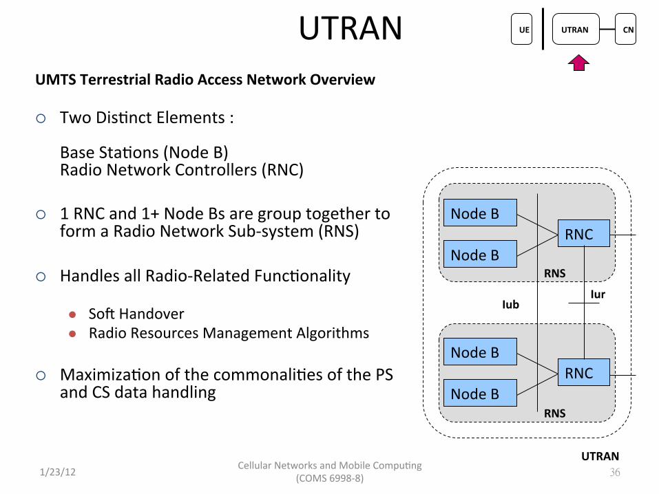
¡ Two Dis5nct Elements :
Base Sta5ons (Node B) Radio Network Controllers (RNC)
¡ 1 RNC and 1+ Node Bs are group together to form a Radio Network Sub-‐system (RNS)
¡ Handles all Radio-‐Related Func5onality l Sok Handover l Radio Resources Management Algorithms
¡ Maximiza5on of the commonali5es of the PS and CS data handling
UMTS Terrestrial Radio Access Network Overview
Cellular Networks and Mobile Compu5ng (COMS 6998-‐8) 1/23/12
37
UTRAN UE UTRAN CN
Node B
Node B RNC
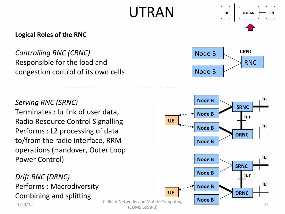
Logical Roles of the RNC
Controlling RNC (CRNC) Responsible for the load and conges5on control of its own cells
CRNC
Node B
Node B SRNC Serving RNC (SRNC)
Terminates : Iu link of user data, Radio Resource Control Signalling Performs : L2 processing of data to/from the radio interface, RRM opera5ons (Handover, Outer Loop Power Control)
Dri2 RNC (DRNC) Performs : Macrodiversity Combining and splitng
Node B
Node B DRNC
Node B
Node B SRNC
Node B
Node B DRNC
UE
UE
Iu
Iu
Iu
Iu
Iur
Iur
Cellular Networks and Mobile Compu5ng (COMS 6998-‐8) 1/23/12

Radio Resources Management
38
• Network Based Func5ons – Admission Control (AC)
• Handles all new incoming traffic. Check whether new connec5on can be admiKed to the system and generates parameters for it.
– Load Control (LC) • Manages situa5on when system load exceeds the threshold and some counter
measures have to be taken to get system back to a feasible load. – Packet Scheduler (PS): at RNC and NodeB (only for HSDPA and HSUPA)
• Handles all non real 5me traffic, (packet data users). It decides when a packet transmission is ini5ated and the bit rate to be used.
• Connec5on Based Func5ons – Handover Control (HC)
• Handles and makes the handover decisions. • Controls the ac5ve set of Base Sta5ons of MS.
– Power Control (PC) • Maintains radio link quality. • Minimize and control the power used in radio interface, thus maximizing the call
capacity.
UE UTRAN CN
Cellular Networks and Mobile Compu5ng (COMS 6998-‐8) 1/23/12

39
Connec5on Based Func5on Power Control ¡ Prevent Excessive Interference
and Near-‐far Effect ¡ Fast Close-‐Loop Power Control
l Feedback loop with 1.5kHz cycle to adjust uplink / downlink power to its minimum
l Even faster than the speed of Rayleigh fading for moderate mobile speeds
¡ Outer Loop Power Control l Adjust the target SIR setpoint in base
sta5on according to the target BER l Commanded by RNC
Fast Power Control If SIR < SIRTARGET, send “power up” command to MS
Outer Loop Power Control If quality < target, increases SIRTARGET
UE UTRAN CN
Cellular Networks and Mobile Compu5ng (COMS 6998-‐8) 1/23/12

40
Connec5on Based Func5on Handover ¡ Soker Handover
l A MS is in the overlapping coverage of 2 sectors of a base staQon
l Concurrent communica5on via 2 air interface channels
l 2 channels are maximally combined with rake receiver
¡ Sok Handover l A MS is in the overlapping coverage of 2
different base staQons l Concurrent communica5on via 2 air interface
channels l Downlink: Maximal combining with rake
receiver l Uplink: Routed to RNC for selec5on
combining, according to a frame reliability indicator by the base sta5on
¡ Hard handover ¡ HSDPA ¡ Inter-‐system and inter-‐frequency
UE UTRAN CN
Cellular Networks and Mobile Compu5ng (COMS 6998-‐8) 1/23/12

41
HSDPA High Speed Downlink Packet Access ¡ Improves System Capacity and User Data Rates in the Downlink Direc5on
to 10Mbps in a 5MHz Channel
¡ Adap5ve Modula5on and Coding (AMC) l Replaces Fast Power Control :
User farer from Base Sta5on u5lizes a coding and modula5on that requires lower Bit Energy to Interference Ra5o, leading to a lower throughput
l Replaces Variable Spreading Factor : Use of more robust coding and fast Hybrid Automa5c Repeat Request (HARQ, retransmit occurs only between UE and BS)
¡ HARQ provides Fast Retransmission with Sok Combining and Incremental Redundancy l Sok Combining : Iden5cal Retransmissions l Incremental Redundancy : Retransmits Parity Bits only
¡ Fast Scheduling Func5on l which is Controlled in the Base Sta5on rather than by the RNC
UE UTRAN CN
Cellular Networks and Mobile Compu5ng (COMS 6998-‐8) 1/23/12
42
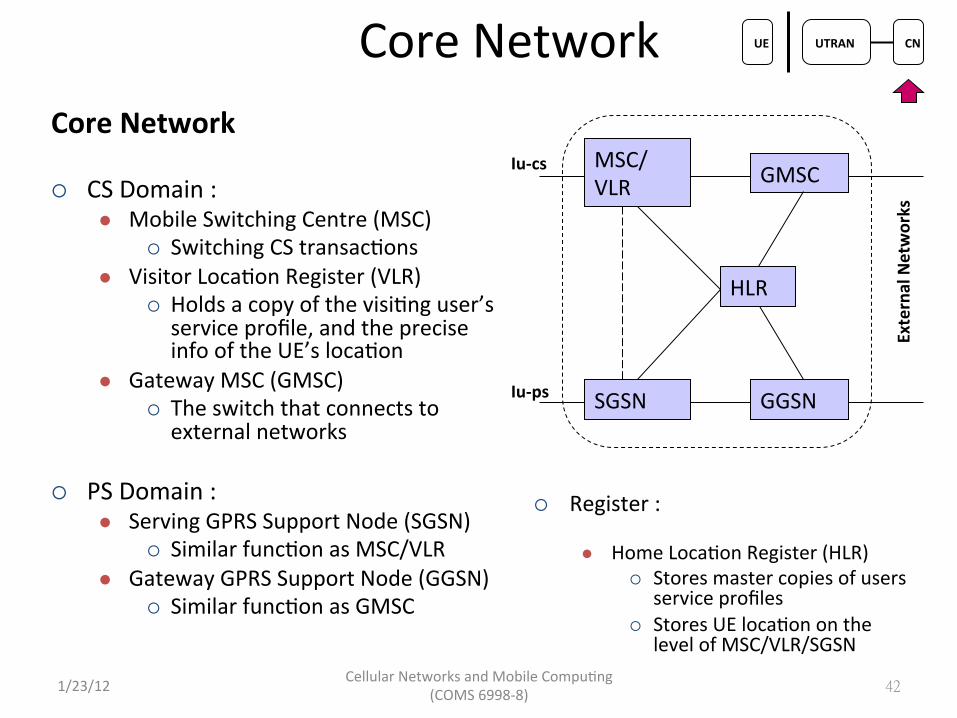
Core Network UE UTRAN CN
MSC/ VLR GMSC
SGSN GGSN
HLR
External Networks
Iu-‐cs
Core Network ¡ CS Domain :
l Mobile Switching Centre (MSC) ¡ Switching CS transac5ons
l Visitor Loca5on Register (VLR) ¡ Holds a copy of the visi5ng user’s service profile, and the precise info of the UE’s loca5on
l Gateway MSC (GMSC) ¡ The switch that connects to external networks
¡ PS Domain : l Serving GPRS Support Node (SGSN)
¡ Similar func5on as MSC/VLR l Gateway GPRS Support Node (GGSN)
¡ Similar func5on as GMSC
¡ Register : l Home Loca5on Register (HLR)
¡ Stores master copies of users service profiles
¡ Stores UE loca5on on the level of MSC/VLR/SGSN
Iu-‐ps
Cellular Networks and Mobile Compu5ng (COMS 6998-‐8) 1/23/12

43
WCDMA Air Interface UE UTRAN CN
Direct Sequence Spread Spectrum
User 1
User N
Spreading
Spreading Received
Despreading
Narrowband
Code Gain
⇒ Frequency Reuse Factor = 1
Wideband
Wideband
⇒ 5 MHz Wideband Signal Allows Mul5path Diversity with Rake Receiver
Wideband
Narrowband
f
f
ff
f
f
t
t
MulQpath Delay Profile
Variable Spreading Factor (VSF)
User 1
Spreading : 256
Wideband f f
User 2
Spreading : 16
Wideband f f⇒ VSF Allows Bandwidth on Demand. Lower Spreading Factor requires Higher SNR, causing Higher Interference in exchange.
Cellular Networks and Mobile Compu5ng (COMS 6998-‐8) 1/23/12
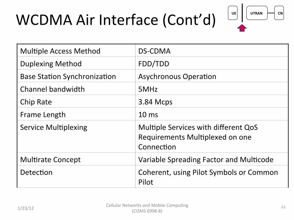
WCDMA Air Interface (Cont’d)
Mul5ple Access Method DS-‐CDMA Duplexing Method FDD/TDD Base Sta5on Synchroniza5on Asychronous Opera5on Channel bandwidth 5MHz Chip Rate 3.84 Mcps Frame Length 10 ms Service Mul5plexing Mul5ple Services with different QoS
Requirements Mul5plexed on one Connec5on
Mul5rate Concept Variable Spreading Factor and Mul5code Detec5on Coherent, using Pilot Symbols or Common
Pilot
44 Cellular Networks and Mobile Compu5ng (COMS 6998-‐8) 1/23/12
UE UTRAN CN

• Channel concepts
Cellular Networks and Mobile Compu5ng (COMS 6998-‐8) 45
UE UTRAN CN
1/23/12
WCDMA Air Interface (Cont’d)

46
WCDMA Air Interface (Cont’d) UE UTRAN CN
Mapping of Transport Channels and Physical Channels
Broadcast Channel (BCH)
Forward Access Channel (FACH)
Paging Channel (PCH) Random Access Channel
(RACH) Dedicated Channel (DCH)
Downlink Shared Channel (DSCH)
Common Packet Channel (CPCH)
Primary Common Control Physical Channel (PCCPCH) Secondary Common Control Physical Channel (SCCPCH) Physical Random Access Channel (PRACH) Dedicated Physical Data Channel (DPDCH) Dedicated Physical Control Channel (DPCCH) Physical Downlink Shared Channel (PDSCH) Physical Common Packet Channel (PCPCH) SynchronizaQon Channel (SCH) Common Pilot Channel (CPICH) AcquisiQon IndicaQon Channel (AICH) Paging IndicaQon Channel (PICH) CPCH Status IndicaQon Channel (CSICH)
Collision DetecQon/Channel Assignment Indicator Channel (CD/CA-‐ICH)
Highly Differentiated Types of Channels enable best combination of Interference Reduction, QoS and Energy Efficiency
Cellular Networks and Mobile Compu5ng (COMS 6998-‐8) 1/23/12

Cellular Networks and Mobile Compu5ng (COMS 6998-‐8) 47
WCDMA Air Interface (Cont’d) UE UTRAN CN
• Code to channel alloca5on
1/23/12

Codes in WCDMA • Channeliza5on Codes (=short code)
– Used for • channel separa5on from the single source in
downlink • separa5on of data and control channels from each
other in the uplink – Same channeliza5on codes in every cell / mobiles
and therefore the addi5onal scrambling code is needed
• Scrambling codes (=long code)
– Very long (38400 chips = 10 ms =1 radio frame), many codes available
– Does not spread the signal – Uplink: to separate different mobiles – Downlink: to separate different cells – The correla5on between two codes (two mobiles/
Node Bs) is low • Not fully orthogonal
48 1/23/12
UE UTRAN CN
Cellular Networks and Mobile Compu5ng (COMS 6998-‐8)
• IDLE: procedures based on recep5on rather than transmission – Recep5on of System Informa5on messages – PLMN selec5on Cell selec5on Registra5on (requires RRC connec5on establishment)
– Recep5on of paging Type 1 messages with a DRX cycle (may trigger RRC connec5on establishment) Cell reselec5on
– Loca5on and rou5ng area updates (requires RRC connec5on establishment)
Cellular Networks and Mobile Compu5ng (COMS 6998-‐8) 49
RRC State Machine �
1/23/12
UE UTRAN CN
• CELL_FACH: need to con5nuously receive (search for UE iden5ty in messages on FACH), data can be sent by RNC any 5me – Can transfer small PS data – UE and network resource required low – Cell re-‐selec5ons when UE mobile – Inter-‐system and inter-‐frequency handoff possible – Can receive paging Type 2 messages without a DRX cycle
Cellular Networks and Mobile Compu5ng (COMS 6998-‐8) 50
RRC State Machine (Cont’d)�
1/23/12
UE UTRAN CN
• CELL_DCH: need to con5nuously receive, and sent whenever there is data – Possible to transfer large quan55es of uplink and downlink data
– Dedicated channels can be used for both CS and PS connec5ons
– HSDPA and HSUPA can be used for PS connec5ons – UE and network resource requirement is rela5vely high – Sok handover possible for dedicated channels and HSUPA Inter-‐system and inter-‐frequency handover possible
– Paging Type 2 messages without a DRX cycle are used for paging purposes
Cellular Networks and Mobile Compu5ng (COMS 6998-‐8) 51 1/23/12
RRC State Machine (Cont’d)� UE UTRAN CN

RRC State Machine (Cont’d)�
• State promo5ons have promoQon delay • State demo5ons incur tail Qmes
Tail Time
Tail Time
Delay: 1.5s
Delay: 2s
Channel � Radio Power �
IDLE � Not allocated �
Almost zero �
CELL_FACH � Shared, Low Speed �
Low�
CELL_DCH � Dedicated, High Speed �
High �
Courtesy: Feng Qian
Cellular Networks and Mobile Compu5ng (COMS 6998-‐8) 1/23/12
UE UTRAN CN

Outline • Wireless communica5ons basics
– Signal propaga5on, fading, interference, cellular principle
• Mul5-‐access techniques and cellular network air-‐interfaces – FDMA, TDMA, CDMA, OFDM
• 3G: UMTS – Architecture: en55es and protocols – Physical layer – RRC state machine
• 4G: LTE – Architecture: en55es and protocols – Physical layer – RRC state machine
Cellular Networks and Mobile Compu5ng (COMS 6998-‐8) 53 1/23/12
Cellular Networks and Mobile Compu5ng (COMS 6998-‐8)
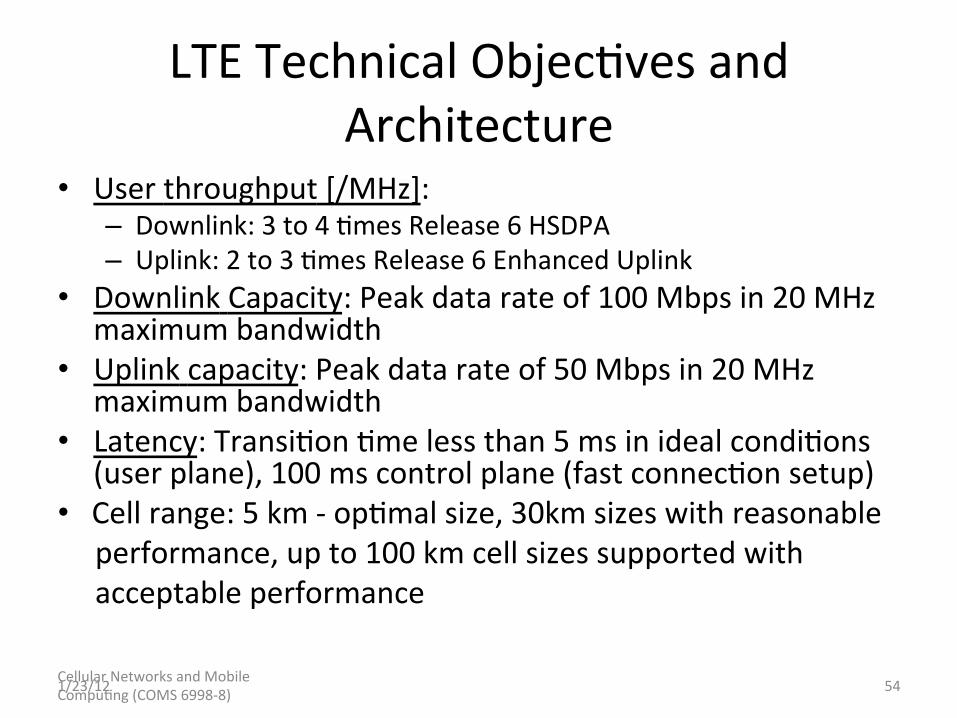
LTE Technical Objec5ves and Architecture
• User throughput [/MHz]: – Downlink: 3 to 4 5mes Release 6 HSDPA – Uplink: 2 to 3 5mes Release 6 Enhanced Uplink
• Downlink Capacity: Peak data rate of 100 Mbps in 20 MHz maximum bandwidth
• Uplink capacity: Peak data rate of 50 Mbps in 20 MHz maximum bandwidth
• Latency: Transi5on 5me less than 5 ms in ideal condi5ons (user plane), 100 ms control plane (fast connec5on setup)
• Cell range: 5 km -‐ op5mal size, 30km sizes with reasonable performance, up to 100 km cell sizes supported with acceptable performance
54 1/23/12

Cellular Networks and Mobile Compu5ng (COMS 6998-‐8)
• Mobility: Op5mised for low speed but suppor5ng 120 km/h – Most data users are less mobile!
• Simplified architecture: Simpler E-‐UTRAN architecture: no RNC, no CS domain, no DCH
• Scalable bandwidth: 1.25MHz to 20MHz: Deployment possible in GSM bands.
LTE Technical Objec5ves and Architecture (Cont’d)
55 1/23/12

LTE Architecture
• En55es and func5onali5es
Cellular Networks and Mobile Compu5ng (COMS 6998-‐8) 56 1/23/12
Mobility anchoring
UE IP address alloca5on Packet filtering
Radio bearer control Inter-‐cell RRM Connec5on mobility Control Radio admission control
NAS security Idle state mobility handling EPS bearer control

LTE Control Plane Protocol Stack
Cellular Networks and Mobile Compu5ng (COMS 6998-‐8) 57 1/23/12

LTE Data Plane Protocol Stack
Cellular Networks and Mobile Compu5ng (COMS 6998-‐8) 58 1/23/12
Cellular Networks and Mobile Compu5ng (COMS 6998-‐8)
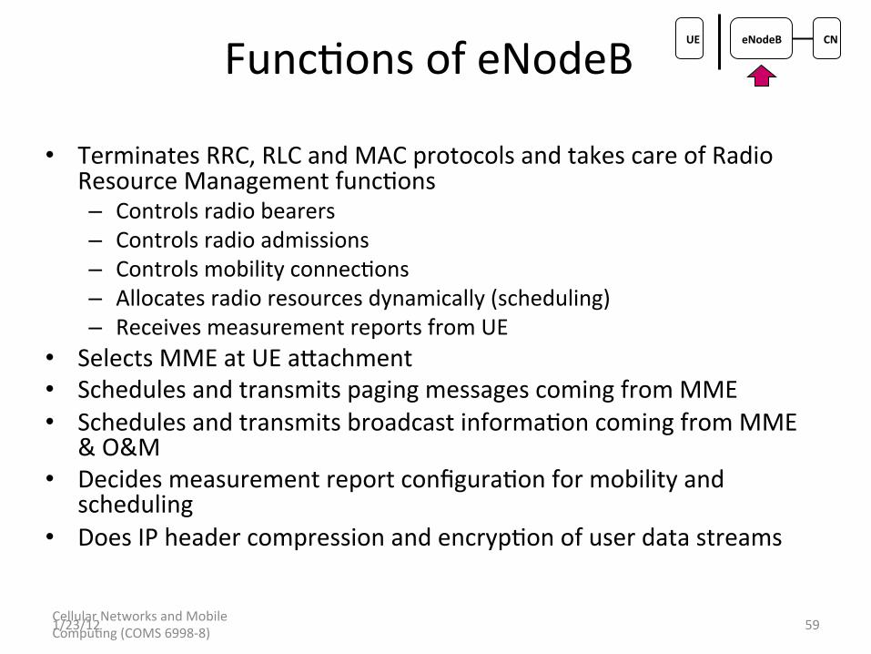
Func5ons of eNodeB
• Terminates RRC, RLC and MAC protocols and takes care of Radio Resource Management func5ons – Controls radio bearers – Controls radio admissions – Controls mobility connec5ons – Allocates radio resources dynamically (scheduling) – Receives measurement reports from UE
• Selects MME at UE aKachment • Schedules and transmits paging messages coming from MME • Schedules and transmits broadcast informa5on coming from MME
& O&M • Decides measurement report configura5on for mobility and
scheduling • Does IP header compression and encryp5on of user data streams
59 1/23/12
UE eNodeB CN

Cellular Networks and Mobile Compu5ng (COMS 6998-‐8)
Func5ons of MME
• Mobility Management En5ty (MME) func5ons – Manages and stores UE context – Generates temporary iden55es and allocates them to UEs
– Checks authoriza5on – Distributes paging messages to eNBs – Takes care of security protocol – Controls idle state mobility – Ciphers & integrity protects NAS signaling
60 1/23/12
UE eNodeB CN

Session Establishment Message Flow
Cellular Networks and Mobile Compu5ng (COMS 6998-‐8) 61 1/23/12
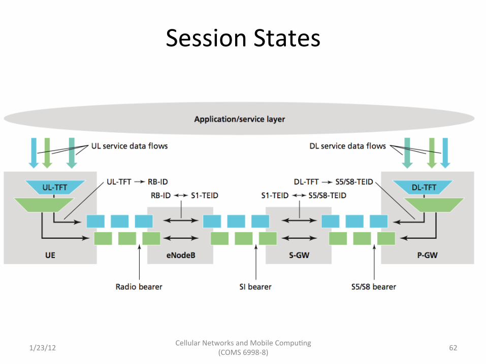
Session States
Cellular Networks and Mobile Compu5ng (COMS 6998-‐8) 62 1/23/12

LTE vs UMTS
GGSN
SGSN
RNC
Node B eNodeB
RNC func5ons moved to eNodeB. • No central radio controller node • OFDM radio, no sok handover • Operator demand to simplify
Mobility Management EnQty MME (not user plane func5ons)
Control plane/user plane split for beKer scalability • MME control plane only • Typically centralized and pooled
PGW SGW
PDN GateWay Serving GateWay
PGW/SGW • Deployed according to traffic demand • Only 2 user plane nodes (non-‐roaming case)
• Func5onal changes compared to the current UMTS Architecture
Cellular Networks and Mobile Compu5ng (COMS 6998-‐8) 63 1/23/12

LTE PHY Basics
• Six bandwidths – 1.4, 3, 5, 10, 15, and 20 MHz
• Two modes – FDD and TDD
• 100 Mbps DL (SISO) and 50 Mbps UL • Transmission technology
– OFDM for mul5path resistance – DL OFDMA for mul5ple access in frequency/5me – UL SC-‐FDMA to deal with PAPR ra5o problem
Cellular Networks and Mobile Compu5ng (COMS 6998-‐8) 64 1/23/12
UE eNodeB CN

Frame Structure Frame Structure Type 1 (FDD)
Frame Structure Type 2 (TDD)
Cellular Networks and Mobile Compu5ng (COMS 6998-‐8) 65 1/23/12
UE eNodeB CN
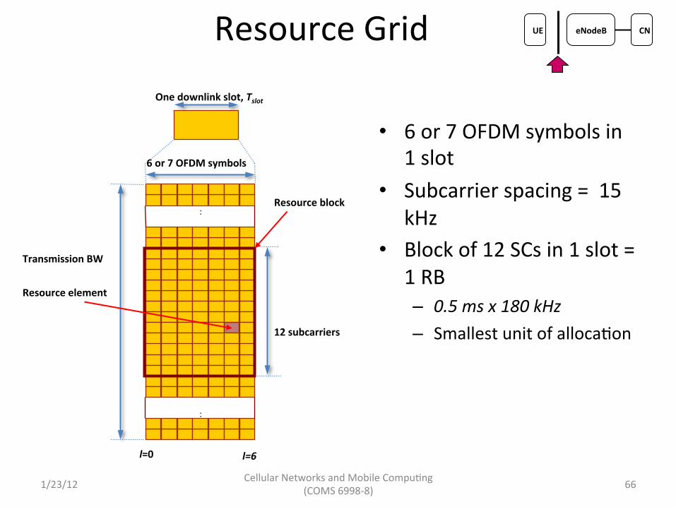
Resource Grid
• 6 or 7 OFDM symbols in 1 slot
• Subcarrier spacing = 15 kHz
• Block of 12 SCs in 1 slot = 1 RB – 0.5 ms x 180 kHz – Smallest unit of alloca5on
6 or 7 OFDM symbols
One downlink slot, Tslot
:
:
Transmission BW
Resource block
Resource element
l=0 l=6
12 subcarriers
Cellular Networks and Mobile Compu5ng (COMS 6998-‐8) 66 1/23/12
UE eNodeB CN
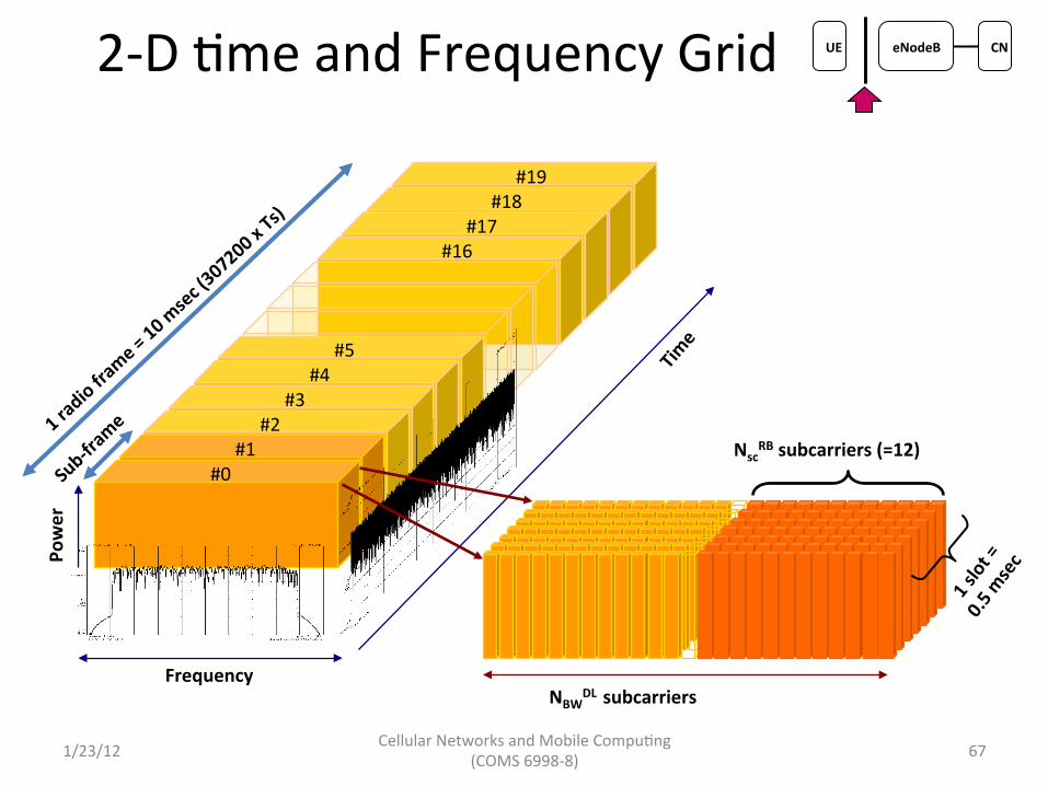
2-‐D 5me and Frequency Grid
Frequency
#0 #1
#2 #3
#4 #5
#19 #18
#17 #16
NBWDL subcarriers
NscRB subcarriers (=12)
Power
Cellular Networks and Mobile Compu5ng (COMS 6998-‐8) 67 1/23/12
UE eNodeB CN

DL PHY Channels and Signals
• Signals: generated in PHY layers – P-‐SS: used for ini5al sync – S-‐SS: frame boundary determina5on – RS: pilots for channel es5ma5on and tracking
• Channels: carry data from higher layers – PBCH: broadcast cell-‐specific info – PDCCH: channel alloca5on and control info – PCFICH: info on size of PDCCH – PHICH: Ack/Nack for UL blocks – PDSCH: Dynamically allocated user data
Cellular Networks and Mobile Compu5ng (COMS 6998-‐8) 68 1/23/12
UE eNodeB CN
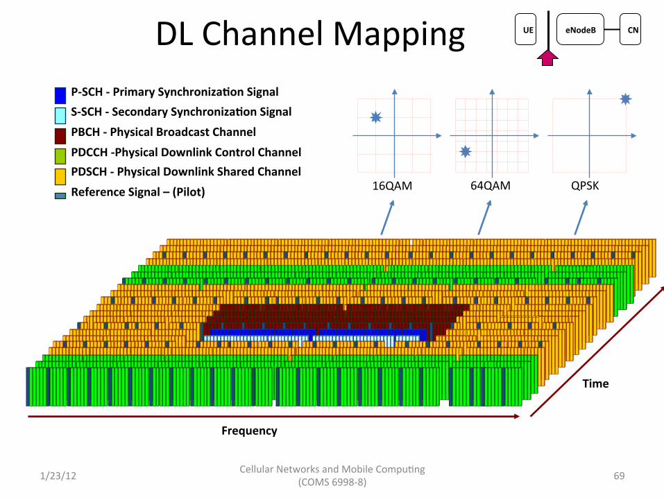
DL Channel Mapping
64QAM 16QAM QPSK
Frequency
Time
P-‐SCH -‐ Primary SynchronizaQon Signal S-‐SCH -‐ Secondary SynchronizaQon Signal PBCH -‐ Physical Broadcast Channel PDCCH -‐Physical Downlink Control Channel PDSCH -‐ Physical Downlink Shared Channel Reference Signal – (Pilot)
Cellular Networks and Mobile Compu5ng (COMS 6998-‐8) 69 1/23/12
UE eNodeB CN

UL PHY Signals and Channels
• Signals: generated in the PHY layer – Demodula5on RS : sync and channel es5ma5on – SRS: Channel quality es5ma5on
• Channels: carry data from higher layers – PUSCH: Uplink data – PUCCH: UL control info – PRACH: Random access for connec5on establishment
Cellular Networks and Mobile Compu5ng (COMS 6998-‐8) 70 1/23/12
UE eNodeB CN

UL Channel Mapping PUSCH DemodulaQon Reference Signal (for PUSCH)
PUCCH DemodulaQon Reference Signal (for PUCCH format 0 or 1, Normal CP)
64QAM 16QAM QPSK
QPSK BPSK
Frequency
Time
Cellular Networks and Mobile Compu5ng (COMS 6998-‐8) 71 1/23/12
UE eNodeB CN

RRC State Machine
• Much simpler than UMTS
Cellular Networks and Mobile Compu5ng (COMS 6998-‐8) 72
Short DRX cycle
Continuous Reception
On Duration
Long DRX cycle
Data transfer Ti expirationTis expiration
Long DRX cycle
Continuous Reception
Short DRX
RRC_CONNECTED RRC_IDLE
Long DRX
DRX
Timer expiration
Data transfer
TtailTis
Ti
1/23/12
UE eNodeB CN

Summary
• Cellular networks are very different from WiFi – Cannot be based on carrier sensing due to large coverage area
– Path must be setup dynamically due to mobility – Need to handle charging func5ons and QoS
• Different physical layer technologies have very different overhead during inac5vity – Dedicated channels prevent others from using the channel
• Frequent RRC state transi5ons in UE can result in high network overhead and UE baKery power consump5on
1/23/12 Cellular Networks and Mobile Compu5ng (COMS 6998-‐8) 73
Ques5ons?


