
5th Year Lec. No. 1 االستاذ أ.د.ضياء جعفر الدباغ
1
Cephalometry
Cephalometry is the analysis and interpretation of standardized
radiographs of the facial bones. In practice, cephalometrics has come to
be associated with a true lateral view ( Fig. 1 ). An antero-posterior
radiograph can also be taken in the cephalostat, but this view is difficult
to interpret and is usually only employed in cases with a skeletal
asymmetry.
Fig.1 A lateral cephalometric radiograph. An aluminium wedge has been positioned to
attenuate the beam thereby enhancing the view of the soft tissues.
INTRODUCTION
Cephalometries had its beginning in craniometry. For many years
anatomists and anthropologists were confined to measuring the
craniofacial dimensions of skulls of dead individuals. This was not
possible in case of living individuals, where the varying thickness of soft
tissues interfered with the accuracy of these measurements. With the
advent of radiography, an alternative method was provided which
enabled the researchers to obtain indirectly but with sufficient accuracy,
and convenience the skeletal measurements of the human skull. The
reproducibility of these radiographs allowed for a longitudinal serial
study of growth of living individuals.

5th Year Lec. No. 1 االستاذ أ.د.ضياء جعفر الدباغ
2
The cephalosatat:
In order to be able to compare the cephalometric radiographs of one
patient taken on different occasions, or those of different individuals,
some standardization is necessary.
To achieve this aim the cephalostat was developed by B. Holly
Broadbent in the period after the First World War ( Fig. 2 ). The
cephalostat consists of an X-ray machine which is at a fixed distance
from a set of ear posts designed to fit into the patient’s external
auditory meatus. Thus the central beam of the machine is directed
towards the ear posts, which also serve to stabilize the patient’s head.
The position of the head in the vertical axis is standardized by ensuring
that the patient’s Frankfort plane (for definition see below) is horizontal.
This can be done by manually positioning the subject or, alternatively, by
placing a mirror some distance away level with the patient’s head and
asking him or her to look into their own eyes. This is termed the natural
head position, and some orthodontists claim that it is more consistent
than a manual approach.
It is normal practice to cone down the area exposed so that the skull
vault is not routinely included in the X-ray beam.
Fig. 2 :Cephalostat
Unfortunately, attempts to standardize the distances from the tube to
the patient (usually between 5 and 6 feet (1.5 to 1.8 m)) and from the
patient to the film (usually around 1 foot (around 30 cm)) have not been
entirely successful as the values in parentheses would suggest.
Some magnification, usually of the order of 7–8 per cent, is inevitable
with a lateral cephalometric film. In order to be able to check the

5th Year Lec. No. 1 االستاذ أ.د.ضياء جعفر الدباغ
3
magnification and thus the comparability of different films, it is helpful if
a scale is included in the view. In order to allow comparisons between
radiographs of the same patient it is essential that the magnification for
a particular cephalostat is standardized.
Indications for cephalometric evaluation:
An increasing awareness of the risks associated with X-rays has led
clinicians to re-evaluate the indications for taking a cephalometric
radiograph
1- An aid to diagnosis
It is possible to carry out successful orthodontic treatment without
taking a cephalometric radiograph, particularly in Class I malocclusions.
However, the information that cephalometric analysis yields is helpful in
assessing the probable aetiology of a malocclusion and in planning
treatment. The benefit to the patient in terms of the additional
information gained must be weighed against the X-ray dosage.
Therefore a lateral cephalometric radiograph is best limited to patients
with a skeletal discrepancy and/or where anteroposterior movement
of the incisors is planned. In a small proportion of patients it may be
helpful to monitor growth to aid the planning and timing of treatment
by taking serial cephalometric radiographs, although again the dosage to
the patient must be justifiable. In addition, a lateral view is often helpful
in the accurate localization of unerupted displaced teeth and other
pathology.
2- A pre-treatment record
A lateral cephalometric radiograph is useful in providing a baseline
record prior to the placement of appliances, particularly where
movement of the upper and lower incisors is planned.
3- Monitoring the progress of treatment
In the management of severe malocclusions, where tooth movement is
occurring in all three planes of space (for example treatments involving
functional appliances, or upper and lower fixed appliances), it may be
helpful to take a lateral cephalometric radiograph during treatment to
monitor incisor inclinations and anchorage requirements.

5th Year Lec. No. 1 االستاذ أ.د.ضياء جعفر الدباغ
4
A lateral cephalometric radiograph may also be useful in monitoring the
movement of unerupted teeth and for assessing upper incisor root
resorption if this is felt to be a potential risk during treatment.
4- Research purposes
A great deal of information has been obtained about growth and
development by longitudinal studies which involved taking serial
cephalometric radiographs from birth to the late teens or beyond.
While the data provided by previous investigations are still used for
reference purposes, it is no longer ethically possible to repeat this type
of study. However, those views taken routinely during the course of
orthodontic diagnosis and treatment can be used to study the effects
of growth and treatment.
Evaluating a cephalometric radiograph
Before starting a tracing it is important to examine the radiograph for
any abnormalities or pathology. For example, a pituitary tumour could
result in an increase in the size of the sella turcica. A lateral
cephalometric view is also helpful in assessing the patency of the airway,
as enlarged adenoids can be easily seen.
A lateral skull radiograph should be hand-traced in a darkened room
with suitable back illumination using a hard pencil and high-quality
tracing paper attached to the radiograph.
The peripheral regions of the radiograph should be masked to highlight
the cranial base and facial complex. Bilateral structures should be
traced independently and then averaged. Alternatively, the landmarks
and tracing can be digitized directly into a computer using specialized
software, which will instantly produce an analysis .
Computer-based cephalometric analysis: The advent of personal
computing has resulted in the development of many commercial and
freely available software packages that allow the digitization and
manipulation of imported cephalometric lateral skull radiographs
(Fig.3). Although landmark identification is still largely under control of
the user, measurement error is significantly reduced because the
software carries it out. However, the main advantage of these

5th Year Lec. No. 1 االستاذ أ.د.ضياء جعفر الدباغ
5
programmes is the versatility they provide, allowing the user to
generate numerous different analyses or even customize their own. In
addition, they can perform superimpositions, undertake prediction
planning for treatment outcome and are extremely useful for planning
orthognathic surgery, with superimposition of profile photographs onto
the cephalometric tracing allowing the prediction of soft tissue
changes associated with surgical jaw movements.
Studies have shown digitizing to be as accurate as tracing a radiograph
by hand and with the increasing use of digital radiographs this now
becoming the norm.
Figure 3: QuickCeph® computer-prediction software for cephalometric
planning
Commonly used cephalometric points and reference lines
The points and reference lines are shown in Fig.(4 ) .
A Point (A): This is the point of deepest concavity on the anterior
profile of the maxilla. It is also called subspinale. This point is taken to
represent the anterior limit of the maxilla and is often tricky to locate
accurately. However, tracing the outline of the root of the upper central
incisor first and shielding all extraneous light often aids identification.
A point is located on alveolar bone and is liable to changes in position
with tooth movement and growth.

5th Year Lec. No. 1 االستاذ أ.د.ضياء جعفر الدباغ
6
Anterior nasal spine (ANS): this is the tip of the anterior process of the
maxilla and is situated at the lower margin of the nasal aperture.
B point (B): the point of deepest concavity on the anterior surface of the
mandibular symphysis. B point is also sited on alveolar bone and can
alter with tooth movement and growth.
Gonion (Go): the most posterior inferior point on the angle of the
mandible. This point can be ‘guesstimated’, or determined more
accurately by bisecting the angle formed by the tangents from the
posterior border of the ramus and the inferior border of the mandible .
Menton (Me): the lowest point on the mandibular symphysis.
Nasion (N): the most anterior point on the frontonasal suture. When
difficulty is experienced locating nasion, the point of deepest concavity
at the intersection of the frontal and nasal bones can be used instead.
Orbitale (Or): the most inferior anterior point on the margin of the orbit.
By definition, the left orbital margin should be used to locate this point.
However, this can be a little tricky to determine radiographically, and so
an average of the two images of left and right is usually taken.
Pogonion (Pog): the most anterior point on the mandibular symphysis.
Porion (Po): the uppermost outermost point on the bony external
auditory meatus. This landmark can be obscured by the ear posts of the
cephalostat, and some advocate tracing these instead. However, this is
not recommended as they do not approximate to the position of the
external auditory meatus. The uppermost surface of the condylar head is
at the same level, and this can be used as a guide where difficulty is
experienced in determining porion.
Posterior nasal spine (PNS): this is the tip of the posterior nasal spine of
the maxilla. This point is often obscured by the developing third molars,
but lies directly below the pterygomaxillary fissure.
Sella (S): the midpoint of the sella turcica.
SN line: this line, connecting the midpoint of sella turcica with nasion, is
taken to represent the cranial base.

5th Year Lec. No. 1 االستاذ أ.د.ضياء جعفر الدباغ
7
Frankfort plane: this is the line joining porion and orbitale. This plane is
difficult to define accurately because of the problems inherent in
determining orbitale and porion.
Mandibular plane: The line joining gonion and menton. This is only one
of several definitions of the mandibular plane, but is probably the most
widely used.
Maxillary plane (Palatal plane): the line joining anterior nasal spine with
posterior nasal spine. Where it is difficult to determine ANS and PNS
accurately, a line parallel to the nasal floor can be used instead.
Functional occlusal plane: a line drawn between the cusp tips of the
permanent molars and premolars (or deciduous molars in mixed
dentition). It can be difficult to decide where to draw this line,
particularly
If there is an increased curve of Spee, or only the first permanent molars
are in occlusion during the transition from mixed to permanent
dentition. The functional plane can change orientation with growth
and/or treatment, and so is not particularly reliable for longitudinal
comparisons.
Fig.4:Commonly used cephalometric points and planes
Assessment of Anteroposterior skeletal pattern
1- Angle ANB: In order to be able to compare the position of the maxilla
and mandible, it is necessary to have a fixed point or plane. The skeletal
pattern is often determined cephalometrically by comparing the

5th Year Lec. No. 1 االستاذ أ.د.ضياء جعفر الدباغ
8
relationship of the maxilla and mandible with the cranial base by means
of angles SNA and SNB. The difference between these two
measurements, angle ANB, is classified broadly as follows:
ANB < 2°= Class III, 2° ≤ ANB ≥ 4°= Class I , ANB > 4°= Class II
If SNA is increased or reduced from the average value, this could be due
to either a discrepancy in the position of the maxilla (as indicated by
point A) or nasion. The following (rather crude) modification is often
used in order to make allowance for this:
Provided the angle between the maxillary plane and the sella–nasion
line is within 5–11°:
• if SNA is increased, for every degree that SNA is greater than 81°,
subtract 0.5° from ANB;
• if SNA is reduced, for every degree that SNA is less than 81°, add
0.5°to ANB.
If the angle between the maxillary plane and the sella–nasion line is not
within 5–11°, this correction is not applicable.
2- Ballard conversion:
This analysis uses the incisors as indicators of the relative position of
the maxilla and mandible. It is easy to confuse a Ballard conversion and
a prognosis tracing (Fig.5), but in the former the aim is to tilt the teeth
to their normal angles (thus eliminating any dento-alveolar
compensation) with the result that the residual overjet will indicate the
relationship of the maxilla to the mandible.
5th Year Lec. No. 1 االستاذ أ.د.ضياء جعفر الدباغ
9
Figure .5: Ballard’s conversion tracing. In the upper tracing, the UI to maxillary plane angle is 124°, whilst
the LI to mandibular plane is 90°. The normal values should be 109° and 93°respectively (the lower ncisor
to mandibular plane value is calculated by subtracting the maxillary–mandibular plane angle (MMPA) from
120°). By adjusting these teeth to their normal values around a fulcrum approximately one-third of the root
length from the apices, it can be seen that the overjet is still increased and therefore the skeletal pattern is class II.
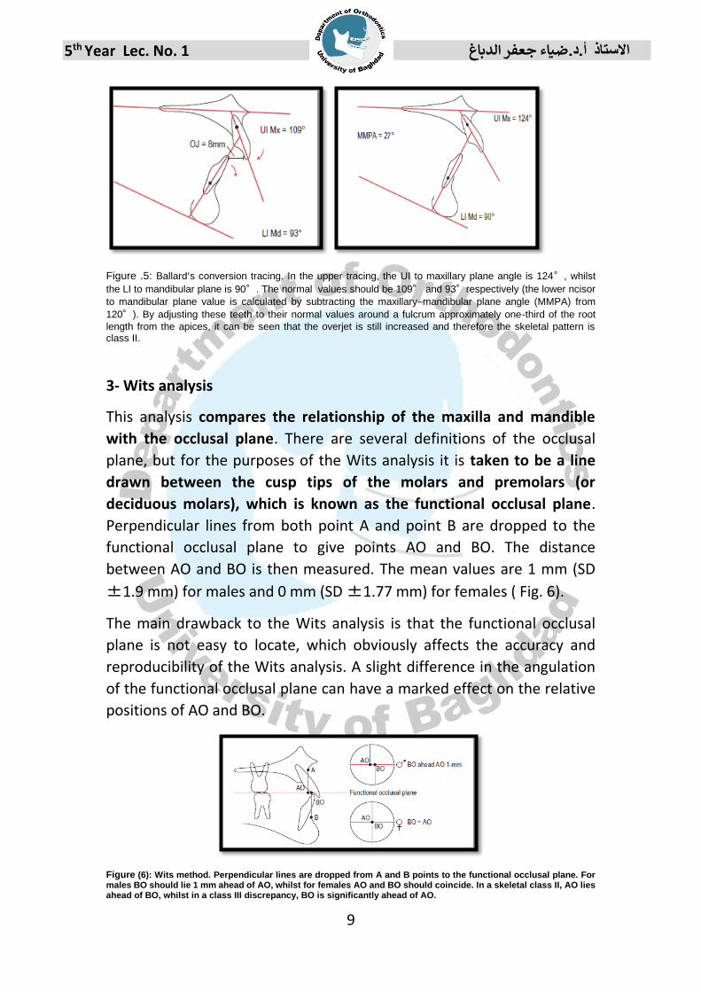
3- Wits analysis
This analysis compares the relationship of the maxilla and mandible
with the occlusal plane. There are several definitions of the occlusal
plane, but for the purposes of the Wits analysis it is taken to be a line
drawn between the cusp tips of the molars and premolars (or
deciduous molars), which is known as the functional occlusal plane.
Perpendicular lines from both point A and point B are dropped to the
functional occlusal plane to give points AO and BO. The distance
between AO and BO is then measured. The mean values are 1 mm (SD
±1.9 mm) for males and 0 mm (SD ±1.77 mm) for females ( Fig. 6).
The main drawback to the Wits analysis is that the functional occlusal
plane is not easy to locate, which obviously affects the accuracy and
reproducibility of the Wits analysis. A slight difference in the angulation
of the functional occlusal plane can have a marked effect on the relative
positions of AO and BO.
Figure (6): Wits method. Perpendicular lines are dropped from A and B points to the functional occlusal plane. For males BO should lie 1 mm ahead of AO, whilst for females AO and BO should coincide. In a skeletal class II, AO lies ahead of BO, whilst in a class III discrepancy, BO is significantly ahead of AO.

5th Year Lec. No. 1 االستاذ أ.د.ضياء جعفر الدباغ
10
Assessing the vertical skeletal relationship The vertical jaw relationship can also be assessed in a number of ways
(Fig.7):
1- Maxillary–mandibular plane angle (MMPA)
The MMPA is a common method for evaluating the vertical jaw
relationship, with horizontal reference planes that are easily located.
The mean value is 27° ± 5°.
2- Frankfort–mandibular plane angle (FMPA)
The FMPA uses the Frankfort plane as a horizontal reference to the
mandibular plane.
This method ignores the maxillary plane, which if affected by a
significant cant can give a misleading value to the vertical jaw
relationship. It is useful to use this measurement in conjunction with the
MMPA plane angle. The mean value is 27° ± 5°.
3- Anterior and posterior face heights
Anterior and posterior face heights are also used as a measure of vertical
facial relationships (Fig.8):
• Total anterior face height (TAFH) extends from nasion to menton, with
both lines constructed perpendicular to the maxillary plane (mean 119
mm in an adult male).
TAFH is further subdivided into: • Upper anterior face height (UAFH); nasion to maxillary plane (mean 54 mm);
• Lower anterior face height (LAFH); maxillary plane to menton (mean 65 mm); and
• Total posterior face height (TPFH) extends from sella to gonion, with both lines
constructed perpendicular to the maxillary plane (mean 79 mm in an adult male).
TPFH is therefore subdivided into:
• Upper posterior face height (UPFH); sella to maxillary plane (mean 46 mm);
• Lower posterior face height (LPFH); maxillary plane to gonion (mean 33 mm);
And • The TPFH should be approximately 65% of the TAFH.
It should be noted that the TPFH (unlike the TAFH) is influenced by a
particularly superior or inferior position of sella and this will affect the
TPFH/TAFH ratio. Referring to the SN–maxillary plane angle can cheque
the relative position of sella within the cranium. The LAFH should be
approximately 55% of the TAFH.

5th Year Lec. No. 1 االستاذ أ.د.ضياء جعفر الدباغ
11
Figure 7: Vertical facial relationships. FMPA, Frankfort–mandibular plane angle; MMPA, maxillary–
mandibular plane angle.
Figure 8: Face heights. LAFH, lower anterior face height; LPFH, lower posterior face height; TAFH, total anterior face height; TPFH, total posterior face height; UAFH, upper anterior face height; UPFH, upper posterior face height Assessing the dental relationship Several methods of assessment are available for positioning the maxillary and mandibular dentition in relation to the jaws and face.
1- Maxillary incisor relationship: The inclination of the most prominent maxillary incisor is constructed using a line through long axis of upper incisor and measured in relation to the
maxillary plane (Fig. 9). The mean value is 109° ± 6°. 2- Mandibular incisor relationship: The inclination of the most
prominent mandibular incisor is constructed using a line through long axis of lower incisor and measured in relation to the
mandibular plane. The mean value is 93° ± 6°; however, mandibular incisor inclination can be influenced by orientation of the mandibular plane. As the mandibular plane becomes steeper, the incisors will tend to retrocline. An alternative method of

5th Year Lec. No. 1 االستاذ أ.د.ضياء جعفر الدباغ
12
evaluating the correct mandibular incisor relationship is to subtract the MMPA from 120.
3- Interincisal angle: The interincisal angle is the angle formed between the most prominent maxillary and mandibular incisors .
The mean value is 135° ± 10°.
Figure 9: Incisor relationships.
A sample of cephalometric tracing
5th Year Lec. No. 1 االستاذ أ.د.ضياء جعفر الدباغ
13
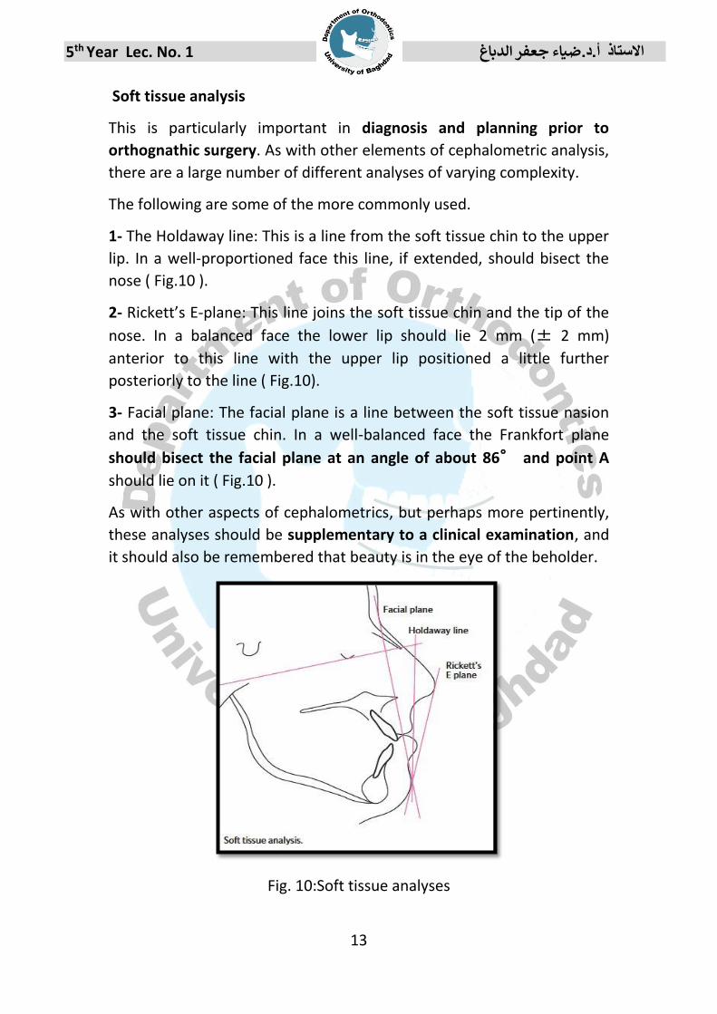
Soft tissue analysis
This is particularly important in diagnosis and planning prior to
orthognathic surgery. As with other elements of cephalometric analysis,
there are a large number of different analyses of varying complexity.
The following are some of the more commonly used.
1- The Holdaway line: This is a line from the soft tissue chin to the upper
lip. In a well-proportioned face this line, if extended, should bisect the
nose ( Fig.10 ).
2- Rickett’s E-plane: This line joins the soft tissue chin and the tip of the
nose. In a balanced face the lower lip should lie 2 mm (± 2 mm)
anterior to this line with the upper lip positioned a little further
posteriorly to the line ( Fig.10).
3- Facial plane: The facial plane is a line between the soft tissue nasion
and the soft tissue chin. In a well-balanced face the Frankfort plane
should bisect the facial plane at an angle of about 86° and point A
should lie on it ( Fig.10 ).
As with other aspects of cephalometrics, but perhaps more pertinently,
these analyses should be supplementary to a clinical examination, and
it should also be remembered that beauty is in the eye of the beholder.
Fig. 10:Soft tissue analyses

5th Year Lec. No. 1 االستاذ أ.د.ضياء جعفر الدباغ
14
Prognosis tracing: Sometimes it is helpful to be able to determine the
type and amount of incisor movement required to correct an increased
or reverse overjet.
Although the skeletal pattern will give an indication, on occasion
compensatory proclination or retroclination (known as dento-alveolar
compensation) of the incisors, can confuse the issue. When planning
treatment in such a case it may be helpful to carry out a prognosis
tracing. This involves ‘moving’ the incisor(s) to mimic the movements
achievable with different treatment approaches to help determine the
best course of action for that patient


