1
Chapter 1: Introduction
This dissertation will describe the mathematical modeling and development of an innovative,three degree-of-freedom robotic manipulator. The new device, which has been named the CarpalWrist, has evolved from the initial stages of invention and concept development, throughtheoretical modeling, design, and prototype fabrication. The work presented in this dissertationis both unique and complete; unique in its creation of a kinematic model of a fundamentally non-traditional robotic wrist structure, and complete in that the model provides the informationneeded for design, development, and application in a wide variety of manipulator tasks at alllevels of performance. Furthermore, while the kinematic and dynamic modeling presented in thisdocument are specific to the new Wrist device, the modeling and analysis techniques haveapplications in other areas of parallel kinematics and robotics. In this respect, while the focusand intent of this report is to fully describe the theoretical modeling of a specific, parallelmanipulator, it will also serve as a fundamental example of analytical treatment techniques forgeneral parallel manipulators.
1.1 Background in Robotics
Flexible automation systems, or robotics, are becoming an increasingly important tool in thisage of competitive, technology-driven production. Many industries are introducing robots intotheir operations to remain competitive and maintain flexibility over shorter product life cycles.Donald Vincent, executive vice president of the Robotics Industries Association pointed to thegrowth in demand of package handling among food and pharmaceutical manufacturers, saying,“the speed of robots are able to justify cost, … The food processing industry is driven by speed,and robots have the speed to do product handling,”(http://www.industr.net/discussions/robotics2.htm). Increasingly, companies are choosing robotsto work with or replace automation equipment for these high-speed tasks when they becomemore complex.
As demands on production, quality, and assembly in manufacturing settings and fullyautonomous capabilities in remote settings are increased, manipulator technology must advanceto meet these needs. Developments in the area of computer control and electrical sensorytechnology have been the most visible, allowing manipulators to become prominent inmanufacturing settings and in replacing humans in service tasks. Meanwhile, R&D in the area ofrobot mechanics, particularly in developing new kinematic structures, has received much lessattention. The vast majority of robotic architectures currently in use were developed in the1970’s. However, advances in robot mechanics with improved manipulator structures are criticalto increasing the bounds on manipulator performance.
Stephen L. Canfield Chapter 1: Introduction 2
1.2 Robot Mechanics
Robot mechanics deals with the many aspects of kinematic and dynamic modeling, hardwaredesign, actuation, and control. Manipulator kinematics is the study of the motion of themanipulator without reference to forces, i.e., the motion resulting from the kinematic constraints.Manipulator dynamics incorporates the kinematic model to relate robot motion to input forces.Other areas of robot mechanics include the following topics: mechanical design of themanipulator components, selecting suitable forms of actuation, meeting the available powersupply, selecting joint and transmission elements, designing tool mounting capabilities, andproviding protection from the operating environment.
1.2.1 Manipulator Kinematics and Dynamics
The fundamental task of a robot is to position and orient a tool in a specified manner. Positionand orientation, taken together will be referred to as pose. The architecture of a roboticmanipulator is selected and designed based on its ability to meet the tool-pose requirements. Themost common manipulator architecture is a serial structure, a structure which consists of a seriesof actuated joints, (rotary and/or linear), forming one path between the tool and ground. To fullyposition and orient a rigid body in space, a six-degree-of-freedom (dof) task, requires a six-degree-of-freedom manipulator. Many tasks require less than six degrees of freedom, however.Therefore such tasks do not require a full six dof manipulator for operation. For example, taskswhich employ an axis-symmetric tool do not require roll orientation. Some tasks require simplepointing orientation, a two-degree-of-freedom task, or spatial point positioning, a three-degree-of-freedom task. In some cases, a two or three dof manipulator will be used as modular sub-components in a larger manipulator system. For example, many six dof serial manipulatorsconsist of two sub-structures; a three dof arm used to position the tool, and a three dof wrist usedto orient the tool.
The mathematical model of each particular manipulator must be developed in order to providethe necessary control of the device. The mathematical model provides a mapping from the inputspace (also called joint space) to the output space (called tool space) of the manipulator. Theinput space consists of a set of coordinates that represent the controlled or actuated joints in themanipulator. The output space consists of a set of coordinates, typically a standardizedcoordinate set such as Cartesian coordinates and Euler angles, that describe the position andorientation (pose) of the tool. This mapping is referred to as kinematic position analysis. Whenthe mapping proceeds from the input space to find the output space coordinates, it is termedforward kinematics. When the mapping proceeds from the output space to input spacecoordinates, it is termed inverse kinematics. For many serial manipulators this mapping isprocedural, following the conventional Denavit-Hartenberg notation (1955) to describe themanipulator through a set of transform equations (Craig, 1989). Parallel manipulators result inhighly non-linear kinematic position mappings. However, the mapping, once known, isperformed as in all manipulators. The inverse kinematics or output to input space mapping is ofmost importance in manipulator control. Here, the output space is known from the desired
Stephen L. Canfield Chapter 1: Introduction 3
manipulator task and the inverse mapping generates the necessary input space parameters forcontrol. To generally locate a rigid tool in space requires six independent parameters. Therefore,a fully general manipulator would be a six-degree-of-freedom (dof) device with sixindependently actuated joints. A manipulator with more than six degrees of freedom couldaccomplish the same task and would be termed redundant. A manipulator may also span only apart of the six degree of freedom space, for example, a three degree-of-freedom manipulator thatprovides orientation only, or conversely a three degree-of-freedom manipulator that providesposition only.
Velocity analysis follows directly from position analysis. As in the position problem, thevelocity or instantaneous kinematics takes the input velocity vector and maps it into the outputvelocity vector through a linear coefficient matrix, referred to as the Jacobian of the manipulator.This analysis is important in defining the size and quality of the available workspace of themanipulator. The available workspace is limited by singularities, and its quality is measuredwith a mathematical definition for dexterity. A manipulator exhibits a “singularity” when it losesone or more output degrees of freedom. Singularities become important when they exist withinthe kinematic workspace (the workspace defined by availability of kinematic position solutions),because they cause difficulties in kinematic control and limit range of applications. In addition tolosing a degree of freedom, the dexterity of the manipulator, (a function of manipulator positionand velocity direction) may show large variations throughout the workspace, demonstrating apoorly dexterous manipulator. Both the singularity and dexterity analyses are derived directlyfrom the system Jacobian.
Finally, a dynamic analysis provides a third mapping between the input actuator torques andthe resulting manipulator position, velocity, and acceleration parameters. In practice, a dynamicanalysis relates the applied input forces to output inertial forces through the equations of motion.Equations of motion can be generated using various approaches. Newton’s Laws and Euler’sRotational Equations, D’Alamberts Principle, and Hamilton’s Principle are common approachesfor dynamic problems (Meirovitch, 1970, Kane, 1972). Further, the coordinate system used todescribe the kinematics can be selected from either canonical forms, such as joint-spacecoordinates, or described using screw-system kinematics. Regardless of the dynamic approach orcoordinate system used for analysis, the results lead to equations of motion which are unique tothe physical device. Selection of approach and coordinates are important in deriving in equationsthat are tractable for manipulation, calculation, and that provide insight to the physical system.
Like the position mapping, the manipulator dynamics can be considered two directional: one amapping which solves the forces required for manipulator motion, called the inverse dynamicsproblem, and one solving for manipulator motion given the input system forces, called the timeresponse or forward dynamics problem. The inverse dynamics are necessary in control, when themanipulator trajectory is given and force requirements from the motors are needed. Thisproblem is also useful in dynamic stress analysis. The time response or forward dynamicsproblem creates a simulation model of the device which can be used in advanced modeling,analysis, and in creating high-level controllers. In both analyses, the results of a dynamic
Stephen L. Canfield Chapter 1: Introduction 4
modeling become important when the manipulator is intended for high-speed operation ormoving a massive payload, resulting in significant inertial loading.
1.3 Robot Architecture
The kinematic architecture of robotic manipulators can be classified as either serial or parallel(or a hybrid of the two). The serial architecture is predominantly used in application for anumber of reasons. In many ways, it resembles the human arm and is therefore an intuitiveconcept. It has advantages such as a large workspace or range of motion. Most importantly, theserial architecture is relatively straightforward to model mathematically. For these reasons, themajority of research into the mechanics of robotics has been in serial devices. However, theserial architecture contains limitations that can only be partially improved through advancedactuation and controls technology. One limitation in particular is the single load-bearing pathconnecting the tool to ground.
An alternative, but much less common architecture for a robotic manipulator is the parallelstructure. The key feature of this architecture is the multiple load-bearing paths that connect thetool to ground. Much like a truss is important in civil structures because of its high rigidity andhigh strength-to-weight ratio, parallel manipulators provide the same advantages in systemswhere accuracy and inertial forces are of primary importance. One common example of aparallel manipulator is the variable-geometry, octahedral truss, a special type of Stewart’splatform, that is used frequently to provide base actuation in motion-capable flight simulators.Primary reasons for a lack of development of parallel-architecture manipulators arecomplications in modeling and analysis and the limited range of motion common to most paralleldevices. Parallel architecture manipulators provide the possibility of improving manipulatorstructures if the necessary kinematics can be developed.
1.4 Robotic Wrists
Most manipulator systems can be considered as two distinct parts, an arm used to position anda wrist used to orient. There are many reasons for using this arm-wrist combination. First, thiscombination tends to decouple robot positioning and orienting functions. Second, thiscombination casts the robot into a form that is guaranteed to have a closed-form kinematicsolution when the wrist motion is spherical (i.e., it provides orientation about a fixed point)(Craig, 1989). Not only does a closed-form position solution allow real-time control of themanipulator, it simplifies the kinematics which aids in motion control activities such as pathplanning and singularity avoidance. Third, this arrangement is conceptually intuitive and isreadily adaptable to a great number of applications, since it approximates the human arm.Fourth, it helps reduce redundancy in the system and, therefore, helps eliminate singularities.
While the arm and the wrist are both necessary and both involve complex design issues, thewrist poses the greatest design complexity to engineers. The wrist must provide orientationabout multiple axes, move about some center position, work in a relatively small envelope, anddo this all while manipulating the entire system payload.
Stephen L. Canfield Chapter 1: Introduction 5
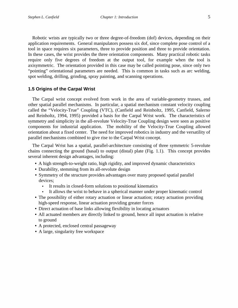
Robotic wrists are typically two or three degree-of-freedom (dof) devices, depending on theirapplication requirements. General manipulators possess six dof, since complete pose control of atool in space requires six parameters, three to provide position and three to provide orientation.In these cases, the wrist provides the three orientation components. Many practical robotic tasksrequire only five degrees of freedom at the output tool, for example when the tool isaxisymmetric. The orientation provided in this case may be called pointing pose, since only two“pointing” orientational parameters are needed. This is common in tasks such as arc welding,spot welding, drilling, grinding, spray painting, and scanning operations.
1.5 Origins of the Carpal Wrist
The Carpal wrist concept evolved from work in the area of variable-geometry trusses, andother spatial parallel mechanisms. In particular, a spatial mechanism constant velocity couplingcalled the “Velocity-True” Coupling (VTC), (Canfield and Reinholtz, 1995, Canfield, Salernoand Reinholtz, 1994, 1995) provided a basis for the Carpal Wrist work. The characteristics ofsymmetry and simplicity in the all-revolute Velocity-True Coupling design were seen as positivecomponents for industrial application. The mobility of the Velocity-True Coupling allowedorientation about a fixed center. The need for improved robotics in industry and the versatility ofparallel mechanisms combined to give rise to the Carpal Wrist concept.
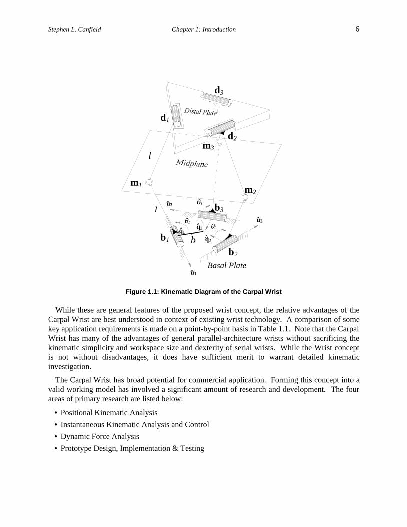
The Carpal Wrist has a spatial, parallel-architecture consisting of three symmetric 5-revolutechains connecting the ground (basal) to output (distal) plate (Fig. 1.1). This concept providesseveral inherent design advantages, including:
• A high strength-to-weight ratio, high rigidity, and improved dynamic characteristics• Durability, stemming from its all-revolute design• Symmetry of the structure provides advantages over many proposed spatial parallel
devices;• It results in closed-form solutions to positional kinematics• It allows the wrist to behave in a spherical manner under proper kinematic control
• The possibility of either rotary actuation or linear actuation; rotary actuation providinghigh-speed response, linear actuation providing greater forces
• Direct actuation of base links allowing flexibility in locating actuators• All actuated members are directly linked to ground, hence all input actuation is relative
to ground• A protected, enclosed central passageway• A large, singularity free workspace
Stephen L. Canfield Chapter 1: Introduction 6
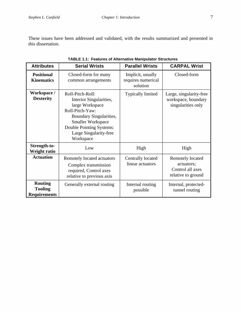
While these are general features of the proposed wrist concept, the relative advantages of theCarpal Wrist are best understood in context of existing wrist technology. A comparison of somekey application requirements is made on a point-by-point basis in Table 1.1. Note that the CarpalWrist has many of the advantages of general parallel-architecture wrists without sacrificing thekinematic simplicity and workspace size and dexterity of serial wrists. While the Wrist conceptis not without disadvantages, it does have sufficient merit to warrant detailed kinematicinvestigation.
The Carpal Wrist has broad potential for commercial application. Forming this concept into avalid working model has involved a significant amount of research and development. The fourareas of primary research are listed below:
• Positional Kinematic Analysis
• Instantaneous Kinematic Analysis and Control
• Dynamic Force Analysis
• Prototype Design, Implementation & Testing
θ1θ2
θ3
û1
û2
û3
m1m2
m3
d3
d1
d2
b1
b2
b3
q2^
q1^ q3^
l
l
b
Basal Plate
Figure 1.1: Kinematic Diagram of the Carpal Wrist
Stephen L. Canfield Chapter 1: Introduction 7
These issues have been addressed and validated, with the results summarized and presented inthis dissertation.
TABLE 1.1: Features of Alternative Manipulator Structures
Attributes Serial Wrists Parallel Wrists CARPAL Wrist
PositionalKinematics
Closed-form for manycommon arrangements
Implicit, usuallyrequires numerical
solution
Closed-form
Workspace /Dexterity
Roll-Pitch-Roll:Interior Singularities,large Workspace
Roll-Pitch-Yaw:Boundary Singularities,Smaller Workspace
Double Pointing Systems:Large Singularity-freeWorkspace
Typically limited Large, singularity-freeworkspace, boundary
singularities only
Strength-to-Weight ratio
Low High High
Actuation Remotely located actuators
Complex transmissionrequired, Control axes
relative to previous axis
Centrally locatedlinear actuators
Remotely locatedactuators;
Control all axesrelative to ground
RoutingTooling
Requirements
Generally external routing Internal routingpossible
Internal, protected-tunnel routing
Stephen L. Canfield Chapter 1: Introduction 8
1.6 Motivation for the New Wrist
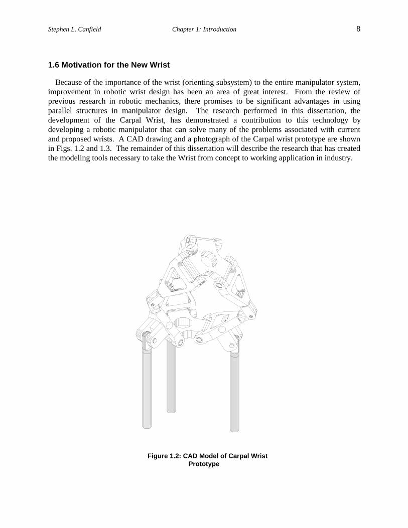
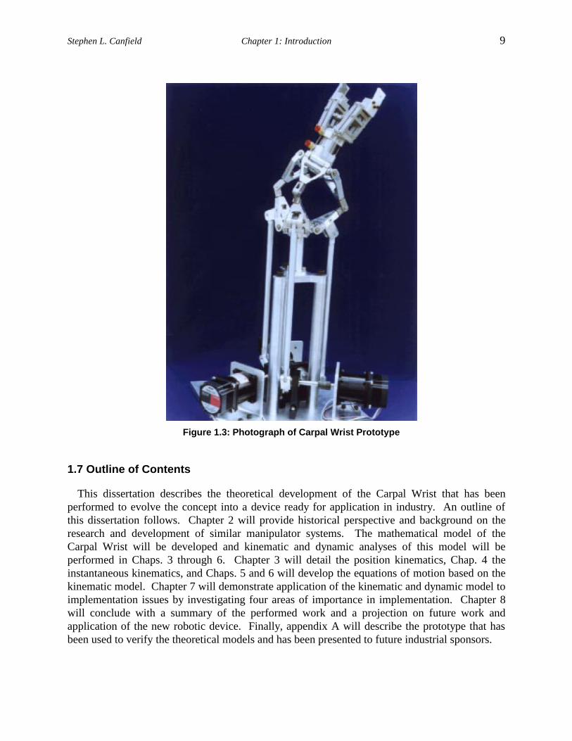
Because of the importance of the wrist (orienting subsystem) to the entire manipulator system,improvement in robotic wrist design has been an area of great interest. From the review ofprevious research in robotic mechanics, there promises to be significant advantages in usingparallel structures in manipulator design. The research performed in this dissertation, thedevelopment of the Carpal Wrist, has demonstrated a contribution to this technology bydeveloping a robotic manipulator that can solve many of the problems associated with currentand proposed wrists. A CAD drawing and a photograph of the Carpal wrist prototype are shownin Figs. 1.2 and 1.3. The remainder of this dissertation will describe the research that has createdthe modeling tools necessary to take the Wrist from concept to working application in industry.
Figure 1.2: CAD Model of Carpal WristPrototype
Stephen L. Canfield Chapter 1: Introduction 9
1.7 Outline of Contents
This dissertation describes the theoretical development of the Carpal Wrist that has beenperformed to evolve the concept into a device ready for application in industry. An outline ofthis dissertation follows. Chapter 2 will provide historical perspective and background on theresearch and development of similar manipulator systems. The mathematical model of theCarpal Wrist will be developed and kinematic and dynamic analyses of this model will beperformed in Chaps. 3 through 6. Chapter 3 will detail the position kinematics, Chap. 4 theinstantaneous kinematics, and Chaps. 5 and 6 will develop the equations of motion based on thekinematic model. Chapter 7 will demonstrate application of the kinematic and dynamic model toimplementation issues by investigating four areas of importance in implementation. Chapter 8will conclude with a summary of the performed work and a projection on future work andapplication of the new robotic device. Finally, appendix A will describe the prototype that hasbeen used to verify the theoretical models and has been presented to future industrial sponsors.
Figure 1.3: Photograph of Carpal Wrist Prototype


