
- 126 -
Chapter 7
Proposed model for building adaptable
Virtual Environments

- 127 -
7. Proposed model for building adaptable Virtual Environments
This chapter presents two contributions, the first contribution is a proposed model for
building adaptable Virtual Environments and the second contribution is the way of manipulating different virtual worlds. Our manipulation technique has been divided into two parts: the first part takes into consideration the viewer´s position in the virtual environment and the second part the navigation of the world. The viewer position is captured by a head-tracker device that allows for the computation of frustums involved in the virtual environment, see chapter 3. The navigation allows doing a tour throughout the virtual world.
Furthermore, in this chapter three virtual environments built with two screens are
described; they are manipulated in different ways. The results obtained in this chapter are published in the journal CiBIyT (Mora, et al., 2009-1) and in the 20th International Conference on Electronics, Communications and Computers. CONIELECOMP 2009 (Mora, et al., 2009-2).
This chapter is organized in the following way:
Section 7.1 describes a general scheme of the project. The work focuses primarily on the
construction of virtual environments that are adaptable to different resources and requirements, meaning they can be constructed with different characteristics, sizes and shapes.
Section 7.2 describes the software used
Section 7.3 presents different configurations using the system characteristics describe in
section 7.1. Section 7.4 describes three ways of manipulating the navigation of our virtual
environments. Section 7.4.1 presents the first virtual environment, which uses a remote control for navigation, Section 7.4.2 presents the second virtual environment, which is manipulated using the viewer position and Section 7.4.3 presents the third virtual environment, which is manipulated hands-free using a head-tracker and time as resources.
Section 7.5 describes the evaluation details of a virtual environment built with two
monitors forming a 90° angle using different manipulation kinds and 3D sound.
Section 7.6 shows the results of the evaluation described in section 7.5 Section 7.7 presents a comparative analysis with the previous work. Finally in section 7.8 there is a chapter summary.

- 128 -
7.1 Project scheme for building Virtual Environments
This section describes the general scheme of the project; this project is devised for the
building of virtual environments, adaptable to different applications and number of resources. This project has a client-server structure, which allows for the use of a set of devices connected via net. In Figure 7.1 the white squares represent the server and the clients. The gray squares represent the virtual worlds and the manipulation kind.
The server manages one or more clients and is responsible for doing a set of tasks. The
server obtains the screen configurations, which refers to their relative position and the angles between them. The server also saves this information (addScreen) and returns the four coordinates of its corners to each screen (calcCoordinates), see section 3.3. The server also updates the viewer position (getInputDevice) through three input devices which include a keyboard, a remote control and a head-tracker. The user can indicate his choice to the server about the virtual world he wants to see (ChooseVirtualWorld). There is a virtual world shown by default. The server indicates to the client(s) what virtual world should be displayed and turns on the 3D sound according to the chosen world (Play3DSound). The navigation is done through a keyboard, a remote control, a head-tracker and files.
Model_View defines the visualization volume (setViewPort) by taking into consideration
the screen orientation and viewer position (offAxisProjection).
Each client reads a configuration file (readConfigFlie) to know the information about its screen. This information includes the real position, the size, the edge size of the screen and information about whether the virtual world is stereoscopic or not. In the construction of stereoscopic environments half of the clients have to display in the right part of the stereoscopic world and the other half of the clients, the left part. The client establishes communication with the server via messages (connectToServer). Then the client sends its screen configuration to the server (screenInformation), and the server returns the information necessary to determine the section of the world that corresponds to the display. The client frequently asks the server for the viewer position (getViewerPosition) as well as the camera position (getCameraPosition) to be able to navigate. The client also receives the choice of the virtual world through the server.

- 129 -
Figure 7.1 General Scheme
Table 7.1 shows the sequence of the system to explain the general scheme.
Table 7.1 System Sequence
Client Server
Reads the screen configuration from a File (readConfigFile), which also indicates if the virtual world should be stereoscopic.
Begins the connection with the server (connectToServer)
Establishes the connection
Sends the screen information (screensInformation)
Computes the physical coordinates (calcCoordinates)
Saves the screen information (addScreen)
Indicates the virtual world to be displayed (user’s choice made through Keyboard or mouse)
Turns on the 3D sound according to the virtual world chosen (see chapter 6)
Asks for the viewer position (getViewerPosition)
Gets the viewer Position from the input-device (getViewerPosition) and sends it to the client
Client readConfigFile
connectToServer
ScreenInformation
getViewerPosition
getCameraPosition
Model_View offAxisFrustum
setViewPort Server calcCoordinates
addScreen
getInputDevice
calcCameraPosition
Choosevirtualworld
Play3DSound
Virtual World
Anaglyphic Museum
Roman Museum
Solar System
Depot
n 1
Manipulation_Kind Keyboard
Remote Control
Head-Tracker
File

- 130 -
Asks for the Camera position (getCameraPosition)
Computes the Camera position (compCameraPosition) and sends it.
7.1.1 Communication model
Figure 7.2 shows the communication model using Client-server. Every client connects to
the server of a local or remote way using the TCP protocol and the port 9923, it allows connecting one or more computers. The clients and the server communicate via messages. Request/response is a message exchange pattern in which a client sends a request message to a server, which receives and processes the request, ultimately returning a message in response.
Figure 7.2 Communication model
The request message can be as follows: -addscreen.- The client sends the screens configuration to the server, containing their
relative position and the angles between them. The server saves this information and returns the four coordinates of its corners to the client.
-getViewerPosition. The client frequently requests the server for the viewer position -getCameraPosition.- The client frequently requests the server for the camera’s position to display the correct image on all screens. There are other request messages, see Figure 7.1.
7.2 Used Software
In this work OpenGL is used for programming the graphic world and OpenAL for
programming the 3D Sound.
OpenGL (Open Graphics Library) was chosen because it is widely used for making graphics and has so many procedures and functions for programming high-quality 3D graphical images.
OpenAL (Open Audio Library) is an audio API, which can be combined perfectly with OpenGL.
These two libraries (OpenGL and OpenAL) are supported by several Operating Systems
including Unix, Linux, Windows and others, unlike DirectX, which runs only on Windows.
Request/response

- 131 -
7.3 Configurations
Figure 7.3 shows three clients locally connected displaying a virtual world. The three
monitors are identical and are being manipulated using a keyboard. The server is not visible in this image.
Figure 7.3 Three clients
Figure 7.4 shows a Wheatstone-type stereoscope, this configuration was built with two
monitors one in front the other, the monitors are displaying a stereo pair. These images are seen from two slightly different positions. The system knows when an environment is stereoscopic via a configuration file; see Table 7.1. Besides, the file indicates if the monitor will have the left image or the right image.
Figure 7.4 Wheatstone-type stereoscope using two laptops
Figure 7.5 shows a Cazes-type stereoscope, this configuration was built with two
monitors, which are displaying a stereo pair. The clients are connected using a wireless network; this environment can be seen using files with a pre-recorded tour.

- 132 -
Figure 7.5 Cazes-type stereoscope using two laptops
7.4 Navigating a Virtual Environment with different Input Devices
In this project first person navigation is applied and three manipulation kinds in virtual
environments are used. Sections 7.4.1, 7.4.2 and 7.4.3 describe different environments and the way they are manipulated.
7.4.1 Manipulating the a Virtual World using a Remote Control
Some computers such as laptops include a remote control for manipulating slides,
programming DVDs, etc. In this work it has been decided to include the use of a remote control for manipulating the navigation of virtual worlds. Generally, the remote control has enough buttons that allow for the manipulation of a virtual world. This device also has the advantage of providing freedom of movement to the viewer. In section 7.1 is explained that the server is responsible for receiving the instructions of the user through input devices, in this case, manipulation is proposed via the remote control.
A simple and interesting environment can be carried out using two screens, two
projectors, one PC, and one remote control. This material is rather common in many Educational Institutions; therefore this environment can be easily constructed without depending on too many resources. See Figure 7.6.

- 133 -
Figure 7.6 virtual environment built with two projections
Figure 7.7 shows the remote control used in this work. It is used sideways so that it can
be operated using both thumbs. This tool allows for manipulation of movement and the rotations of navigation; additionally it has buttons for manipulating viewer position.
Figure 7.7 Remote Control
The left thumb is placed over the white cross and it is used for the movement in the
navigation, while the right thumb is for turning. Although there is no cross for the right thumb, the turning functions are laid out as if there was one. Due to the fact that there are enough buttons, the user is able to have full control over the environment.
7.4.2 Manipulating a Virtual Environment considering of Viewer Position
A common way to manipulate a virtual environment is using a head-tracker to recognize
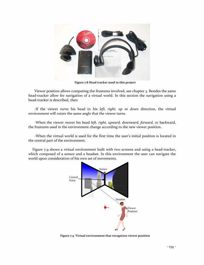
viewer´s position. The head tracker used in this project is shown in Figure 7.8, it is a five-axis game controller that can be manipulated with the head.
Move Right
Move Backward
Move Left
Move Downwards
Move Upward
Move Forward
Go Home
Viewer Position Downwards
Turn Left
Turn Downwards
Turn Right
Viewer Position: Right
Turn Upwards
Viewer Position: Left
Viewer Position: Upwards
- 134 -
Figure 7.8 Head tracker used in this project
Viewer position allows computing the frustums involved, see chapter 3. Besides the same
head-tracker allow for navigation of a virtual world. In this section the navigation using a head-tracker is described, then
-If the viewer turns his head to his left, right, up or down direction, the virtual
environment will rotate the same angle that the viewer turns.
-When the viewer moves his head left, right, upward, downward, forward, or backward, the frustums used in the environment change according to the new viewer position.
-When the virtual world is used for the first time the user’s initial position is located in
the central part of the environment.
Figure 7.9 shows a virtual environment built with two screens and using a head-tracker, which composed of a sensor and a headset. In this environment the user can navigate the world upon consideration of his own set of movements.
Figure 7.9 Virtual environment that recognizes viewer position
Viewer Position
Sensor
Headset
Central Point

- 135 -
With the same idea as in section 7.4.1 we have tried to build a simple environment, although, it is important to remember that our system is able to have any number of screens.
7.4.3 Head-Tracker for hands-free navigation of a Virtual World using the user’s movements in function of time
This environment provides the opportunity for full navigation. This method uses a head-
tracker and the movements are produced in a function of time that the user considers suitable. To begin the system, the viewer needs to complete the following steps:
1) Choose a position where the user navigates the environment. This position can be the
center of the real environment or in front of the monitors when they are used. When the viewer is in the initial position and is looking towards the front, the virtual world remains static.
2) If the viewer keeps turning his head P degrees either left, right, upward or downward
the virtual world will turn to the side where the viewer head is turned as long as the viewer remains with his head turned. When the user returns his head towards the front, the virtual world stops turning.
Figure 7.10 shows a virtual environment and a user using a head-tracker formed of a
sensor and a headset. This environment is built with two non-coplanar screens which form a ninety-degree angle. The head-tracker is able to detect viewer rotations on the x and y axes. The sensor is placed above both screens. An imaginary protractor is drawn on plane xz, this protractor shows the angle around the y axis. If the viewer is viewing the initial point, then the angle registered by our head-tracker is 90o.
Figure 7.10 A virtual environment formed with two projections
<90o >90o
Center of the screens 90o,90o
HeadSet
Sensor

- 136 -
Figure 7.11 shows another imaginary protractor on plane yz, to indicate to us the angle around the x axis. If the viewer has a view height at the center of the screens, the angle registered by our head-tracker is 90o.
Figure 7.11. The environment seen from profile
Therefore, when the viewer turns his head to the left the angle registered on the y axis will be between 0 and 89o, and if he turns his head to the right, the angle registered will be between 91o and 180o.
It is the same situation when the viewer turns his head upwards or downwards, the angles
will be registered between 0o and 180o. Due to the fact that our system allows for unrestricted virtual navigation, when the viewer
moves his head Q centimeters to the left, to the right, upwards, downwards forward or backwards, the environment is programmed to move R steps to the side where the viewer head moves during the time the viewer remains with his head in the adopted position, and stops when the user returns his head to the initial position.
Several trials have been performed to determine the most comfortable head turns. The results are shown in Figure 7.12.
Figure 7.12.1 shows an environment view as seen from above. -The black lines represent the screens (which can be monitors or projections). -The gray point is a sensor. -The black point represents the head-tracker and it is placed in the ideal position for
navigating the environment. In this position the viewer can see virtual environment, displayed through both screens, without problems.
Figure 7.12.2 shows an environment seen by profile. The black line represents both
screens (which can be monitors or projection screens). -The gray point is a sensor. -The black point represents the head-set.
Finally, in both figures can be seen the viewer´s turns which allow rotating the virtual world.
90o,90
o
>90o
<90o
Sensor
HeadSet

- 137 -
1 2
Figure 7.12 1)Environment seen from above. 2)Environment seen by profile
7.5 Evaluating a Virtual Environment built with two monitors forming a 90° angle
This section shows the evaluation of a virtual environment built with two screens forming
a 90 degrees angle between them, this configuration was presented in section 6.3. In this configuration three manipulation kinds are presented. This evaluation also includes the use of keyboard and predefined files for manipulating a virtual world. Each user watched four virtual worlds using sound and the same virtual worlds without sound. The trial duration for every user was 20 minutes. The following input devices were used: Head-tracker, keyboard and remote control. In the trials some topics were focused on the multi-screen display, the manipulation and the sound, see Table 7.2.
Table 7.2 topics for discussion on evaluating a multi-screen virtual environment
Display of multi-screen
Manipulation
3D Sound
Continuity
Ease of use
Improvement of the interaction using sound
Coherence
Practical
Coincidence between sound sources and objects
The screen frames can be considered as simple obstacles in the virtual world.
Coherence between manipulating and results
Improvement of the object location using 3D sound
3D produces feedback
3D sound provides extra information
115o
50o
Sensor
Head Set
Rotate upward
There is no rotation around x axis
Rotate Downward
50o
120o
Sensor
Rotate to the left
Rotate to the right
There is
no rotation around axis y

- 138 -
7.6 Results of evaluating a Virtual Environment built with two monitors
A multi-screen virtual environment was tested by 20 users. The results of the evaluation
are shown in this section. The evaluations are separated in three modules: the first module evaluates the displaying. The second module evaluates sound. Finally, the manipulation and different input devices are evaluated.
Figure 7.13 shows the results of the displaying module. 95% of the users could see a
continuous virtual worlds, 95% of them appreciated coherence in the virtual world displayed on two screens and 100% of the user evaluated the screen frames as a simple obstacle.
Figure 7.13. Results of the evaluation of displaying of a multi-screen virtual environment
Figure 7.14 shows the results of the sound module. 100% of the users considered an
important improvement on using 3D sound in the different virtual worlds. 95% of the users could perceive that the sound sources were emitted from different 3D objects and notice an improvement in the location of 3D objects when the sound sources were incorporated. All the users considered that the sound can be used as feedback and provides extra information.
Figure 7.14. Results of the evaluation of sound
- 139 -
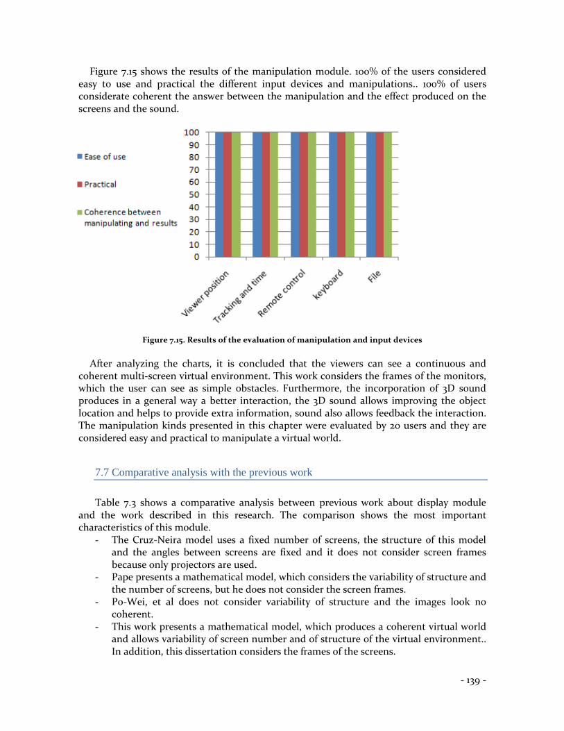
Figure 7.15 shows the results of the manipulation module. 100% of the users considered easy to use and practical the different input devices and manipulations.. 100% of users considerate coherent the answer between the manipulation and the effect produced on the screens and the sound.
Figure 7.15. Results of the evaluation of manipulation and input devices
After analyzing the charts, it is concluded that the viewers can see a continuous and
coherent multi-screen virtual environment. This work considers the frames of the monitors, which the user can see as simple obstacles. Furthermore, the incorporation of 3D sound produces in a general way a better interaction, the 3D sound allows improving the object location and helps to provide extra information, sound also allows feedback the interaction. The manipulation kinds presented in this chapter were evaluated by 20 users and they are considered easy and practical to manipulate a virtual world.
7.7 Comparative analysis with the previous work
Table 7.3 shows a comparative analysis between previous work about display module
and the work described in this research. The comparison shows the most important characteristics of this module.
- The Cruz-Neira model uses a fixed number of screens, the structure of this model and the angles between screens are fixed and it does not consider screen frames because only projectors are used.
- Pape presents a mathematical model, which considers the variability of structure and the number of screens, but he does not consider the screen frames.
- Po-Wei, et al does not consider variability of structure and the images look no coherent.
- This work presents a mathematical model, which produces a coherent virtual world and allows variability of screen number and of structure of the virtual environment.. In addition, this dissertation considers the frames of the screens.

- 140 -
Table 7.3 Comparative analysis between other display models and the proposed of this research
Variability of
number of screens
Coherence between screens
Variability of structure of
the environment
Variability of
angles between screens
Consideration
for screen Frames
Cruz-Neira, et al
No
Yes
No
No
No
Pape, et al.
Yes
Yes
Yes
Yes
No
Po-Wei, et al
No
No
No
No
No
Mora
Yes
Yes
Yes
Yes
Yes
Table 7.4 shows a comparative analysis between previous work about projection module
and the work described in this document. - Jalkanen presents a configuration and shows formulae for calculating the distance
used from a projector to the screen using mirrors, she does not determine the room size where a CAVE will be placed.
- Aguilera presents four configurations for placing a CAVE. He shows four configuration and the physical requirements, which are computed using a system, but he does not specific a mathematical model.
- Our work present four configurations, every configuration with its mathematical proposed for determining the area of the room where a CAVE will be placed. The fourth proposed model allows determining different configurations, and it considers different distances between the projectors and the mirrors, different angles of the mirrors and different rotations among the CAVE walls and the room walls. In addition a system is presented, which allow calculating different configurations and uses the fourth proposed model.
Table 7.4 Comparative analysis between the previous work of the projection module and the
proposed of this research
Number of
configurations
Equations for determining
the room size
Determination
of room size
System
Jalkanen
1
Yes
No
No
Aguilera
4
No
Yes
Yes
Mora
4
Yes
Yes
Yes

- 141 -
Table 7.5 shows a comparative analysis between three stereoscopes and the work described in this document.
- The Cazes-type stereoscope was built using static and small stereo pairs, which did not use sound.
- In this dissertation a proposed model of a Cazes-type digital stereoscope was described. In addition a mathematical description was offered for determining the size of the mirrors. The result is a stereoscope of variable size, which uses two monitors; the stereo pair is a dynamic virtual world, additionally this model use 3D sound.
- The Wheatstone-type stereoscope was built using static and small stereo pairs, and it did not use sound.
- In this research a proposed model of a Wheatstone-type digital stereoscope was described. In addition a mathematical description was presented for determining the dimensions of the stereoscope. The result is a stereoscope of variable size, which uses two monitors or projectors; the stereo pair can be a dynamic virtual world and this stereoscope incorporate 3D sound.
- The Boxed-type stereoscope was built using static and small stereo pairs. - In this work a model of a Boxed-type digital stereoscope was proposed. The result is
a stereoscope, which shows dynamic and small stereo pairs, which use 3D sound.
Table 7.5 Comparative analysis between three stereoscopes and the proposed of this research
Stereoscope
Size
Static/Dynamic
Stereo Pair
Sound
Cazes- type stereoscope
Small
Static
Cards
No
Cazes- type digital stereoscope
Variable
Dynamic
Monitors
Yes
Wheatstone- type stereoscope
Small
Static
Cards
No
Wheatstone- type digital
stereoscope
Variable
Dynamic
Monitors or projectors
Yes
Boxed- type stereoscope
Small
Static
Cards
No
Boxed- type digital stereoscope
Small
Dynamic
Monitor
Yes
Table 7.6 shows a comparative analysis between previous work about sound module and
the work described in this document. - Ying detects collisions between a specific object and the surrounding objects. Ying
designs a system for providing visual feedback, and/or 3D auditory feedback during the manipulation.

- 142 -
- Wu uses one sound source changing its position for evaluating the improvement of the location of sound using dynamic movement of the human head.
- Sodnik evaluates the perception and location of 3D sound in a tabletop augmented reality environment. He uses nine sound sources corresponding to airplanes within a small virtual world.
- Our work presents four different virtual worlds. The first is a depot, which contains three sound sources; the second and the third are art galleries with one sound source respectively (background music); and the fourth is a computing center with nine sound sources with spoken explanation. In all these virtual environments the sound sources are used as feedback to some activities, to locate 3D objects, and as background music.
Table 7.6 Comparative analysis between previous work of sound module and the proposed of this
research
Title
Number sound
sources
Kind of sound
3D sound
Sound is used:
Ying, et al.
No specified
Sounds of a
specific object
Yes
As feedback to some activities
Wu, et al.
1
Sound
Yes
To locate objects
3D
Sodnik, et
al.
Variable
Sound of airplanes
Yes
To locate objects
3D
Mora
9
Spoken
explanation, sounds, music
Yes
As feedback to some activities To locate 3D
objects To background
music
7.8 Summary
This section describes our system, which has a client-server structure, where the server is
responsible of managing one or more clients (screens). Due to its structure, this project allows the construction of different virtual environments. A screen is configured by its position and orientation in the real world, every client sends output information to the screen depending of its position and the navigation of the user, therefore each screen will display a part of a virtual world. This project contains four virtual worlds and the navigation through them is done using a keyboard, a remote control, a head-tracker, or input files.

- 143 -
The kinds of manipulation are discussed in this chapter, and were reviewed using simples virtual environments. The first manipulation was done using a remote control. Currently, many computers include a remote control for manipulating DVDs, moving slides of presentations, etc. In the second manipulation, a head-tracker is used for determining the viewer position and for navigating the virtual world. This manipulation is common in virtual environments; the disadvantage is that when the space is limited, the navigation can also be limited. In the third manipulation, a head-tracker was used and the movements were produced depending of the time that the user maintained his head turned. This manipulation can be useful in limited spaces and is easy to use. Finally, different configurations are shown in section 7.5, these configurations are using the system described in this chapter.
An evaluation of a multi-screen virtual environment using 3D sound and different
manipulations was carried out. The results demonstrate that the viewers can see a continuous and coherent virtual world on multiple screens. In addition, the results also indicate that 3D sound improves the interaction, improves the location of the 3D object and improves the feedback in the virtual environment. Finally, the manipulations used were considered by the users as easy and practical for virtual worlds.


