
THE APPLIANCE IS FOR USE WITHNATURAL GAS OR L.P.G. (Cat II 2H3P TYPE C13 & C33)
NATURAL GAS: 24Ri GC NUMBER 41-311-6518Ri GC NUMBER 41-311-7715Ri GC NUMBER 41-311-7512Ri GC NUMBER 41-311-63
LIQUID PETROLEUM GAS: 24Ri GC NUMBER 41-311-6618Ri GC NUMBER 41-311-7815Ri GC NUMBER 41-311-7612Ri GC NUMBER 41-311-64
GB/IE
CHECKLIST & serviceinterval record is printed at the rear ofthis manual

INSTALLATION &SERVICING INSTRUCTIONS
INSTALLATION & SERVICING INSTRUCTIONS FOR WORCESTER BOSCH GREENSTAR Ri8 716 109 699a (05/05)
1
WORCESTER BOSCH:
TECHNICAL: 08705 266241SERVICE: 08457 256206SPARES: 01905 752571LITERATURE: 01905 752556TRAINING: 01905 752526SALES: 01905 752640WEBSITE: www.worcester-bosch.co.uk
WATER TREATMENT:
FERNOX 01799 550811www.fernox.com
SENTINEL 0151 420 9595www.betzdearborn.com/sentinel
FLUE TERMINAL GUARD:
TOWER FLUE COMPONENTSVALE RISETONBRIDGETN9 1TBTEL: 01732 351680www.tfc-group.co.uk
PLEASE READ THESE INSTRUCTIONS CAREFULLY BEFORE STARTING INSTALLATION.
THESE INSTRUCTIONS ARE APPLICABLE TO THE WORCESTER BOSCH APPLIANCEMODEL(S) STATED ON THE FRONT COVER OF THIS MANUAL ONLY AND MUST NOT BEUSED WITH ANY OTHER MAKE OR MODEL OF APPLIANCE.
THE INSTRUCTIONS APPLY IN THE UK ONLY AND MUST BE FOLLOWED EXCEPT FOR ANYSTATUTORY OBLIGATION.
THIS APPLIANCE MUST BE INSTALLED BY A COMPETENT PERSON. FAILURE TO INSTALLCORRECTLY COULD LEAD TO PROSECUTION.
IF YOU ARE IN ANY DOUBT CONTACT THE WORCESTER BOSCH TECHNICAL HELPLINE.
DISTANCE LEARNING AND TRAINING COURSES ARE AVAILABLE FROM WORCESTERBOSCH.
PLEASE LEAVE THESE INSTRUCTIONS WITH THE COMPLETED BENCHMARK CHECK-LIST (OR A CERTIFICATE CONFIRMING COMPLIANCE WITH IS 813 EIRE ONLY) AND USERGUIDE WITH THE USER OR AT THE GAS METER AFTER INSTALLATION ORSERVICING.
NOTE: THE BENCHMARK CHECKLIST & SERVICE INTERVAL RECORD CAN BE FOUNDAT THE REAR OF THESE INSTRUCTIONS.
ABBREVIATIONS USED IN THIS MANUAL:Ø DiameterNG Natural GasLPG Liquid Petroleum GasCH Central HeatingDHW Domestic Hot WaterIP Ingress ProtectionSEDBUK Seasonal Efficiency of Domestic Boilers in the United Kingdom
CONTACT INFORMATION INSTALLATION & SERVICING INSTRUCTIONS
SYMBOLS USED IN THIS MANUAL:
LIFTING AND CARRYING PRECAUTIONS:• Lift only a manageable weight, or ask for
help. • When lifting the boiler, bend the knees,
and keep the back straight and feet apart. • Do not lift and twist at the same time. • Lift and carry the boiler close to the body• Wear protective clothing and gloves to
protect from any sharp edges
STORE THE APPLIANCE IN A DRYAREA PRIOR TO INSTALLATION.

SAFETY & REGULATIONS
SAFETY PRECAUTIONS & SYMBOLS 3
INSTALLATION REGULATIONS 3
APPLIANCE INFORMATION
GENERAL INFORMATION 4
TECHNICAL DATA 5
LAYOUT & COMPONENTS 6
PRE-INSTALLATION
CLEANING PRIMARY SYSTEMS 7
MAINS SUPPLY 8
WATER SYSTEMS & PIPEWORK 9
CONDENSATE PIPEWORK 10
BOILER LOCATION & CLEARANCES 11-12
PLUMBING MANIFOLD 13
FLUE TERMINAL POSITIONS 14
FLUE OPTIONS 15
INSTALLATION
UNPACKING THE BOILER 16
WALL MOUNTING PLATE / FLUE OPENING 17
OUTER CASE REMOVAL 18
BOILER CONNECTIONS (GAS/WATER) 19
FLUE INSTALLATION 20-22
CONDENSATE CONNECTIONS 23
ELECTRICS 24
POSITION OF WIRED COMPONENTS 25
COMMISSIONING
PRE-COMMISSIONING CHECKS 26
FILLING THE SYSTEM 27
STARTING THE APPLIANCE 28
WATER TREATMENT 29
COMMISSIONING 30
FINISHING COMMISSIONING 31
SERVICING & SPARES
INSPECTION AND SERVICE 32-37
SETTING THE GAS / AIR RATIO 38-39
REPLACEMENT OF PARTS 40-44
SHORT PARTS LIST 45
CONVERSION KITS
GAS. CONVERSION 46
FAULT FINDING & DIAGNOSIS
ELECTRICAL WIRING DIAGRAM 47
FAULT FINDING 48
MAIN FUNCTION 49
BENCHMARK CHECKLIST & SERVICE RECORD SHEET PRINTED AT THE REAR OF THE
MANUAL
CONTENTS
CONTENTSINSTALLATION & SERVICING INSTRUCTIONS FOR WORCESTER BOSCH GREENSTAR Ri8 716 109 699a (05/05)
2
SA
FETY
&R
EG
ULA
TIO
NS
AP
PLI
AN
CE
INFO
RM
ATIO
NP
RE
-IN
STA
LLAT
ION
INS
TALL
ATIO
NC
OM
MIS
SIO
NIN
GS
ER
VIC
ING
& S
PAR
ES
CO
NVE
RS
ION
KIT
SFA
ULT
FIN
DIN
G&
DIA
GR
AM
S

SAFETY PRECAUTIONS& INSTALLATION REGULATIONS
INSTALLATION & SERVICING INSTRUCTIONS FOR WORCESTER BOSCH GREENSTAR Ri8 716 109 699a (05/05)
3
SA
FETY
&R
EG
ULA
TIO
NS
SAFETY PRECAUTIONS INSTALLATION REGULATIONS
IF YOU SMELL GAS:
DON’T SMOKE OR STRIKE MATCHES
DON’T TURN ELECTRICAL SWITCHES ON OR OFF
DO PUT OUT NAKED FLAMES
DO OPEN DOORS AND WINDOWS
DO KEEP PEOPLE AWAY FROM THE AREA AFFECTED
DO TURN OFF THE CONTROL VALVE AT THE METER
DO CALL YOUR GAS COMPANY
A Benchmark Checklist is provided by the manufacturer for the installer to complete including their CORGI registration number to confirm that the boiler has been installed, commissioned and serviced according to the manufacturer’s instructions.
IMPORTANT: The completed Benchmark Checklist will be required in the event of any warranty work and may be required by the local Building Control Inspector.
HEALTH & SAFETY
The appliance contains no asbestos and no substances have been used in theconstruction process that contravene the COSHH Regulations (Control of SubstancesHazardous to Health Regulations 1988).
COMBUSTIBLE AND CORROSIVE MATERIALS
Do not store or use any combustible materials (paper, thinners, paints etc.) inside orwithin the vicinity of the appliance.Chemically aggressive substances, such as halogenated hydrocarbons containingchlorine or fluorine compounds can corrode the appliance and invalidate any warranty.
FITTING & MODIFICATIONS
Fitting the appliance and any controls to the appliance may only be carried out by acompetent engineer in accordance with the current Gas Safety (Installation and Use)Regulations.Flue systems must not be modified in any way other than as described in the fittinginstructions. Any misuse or unauthorised modifications to the appliance, flue orassociated components and systems could invalidate the warranty. The manufactureraccepts no liability arising from any such actions, excluding statutory rights.
SERVICING
Advise the user to have the system serviced annually by a competent, qualifiedengineer (such as British Gas or CORGI registered personnel) using approved spares,to help maintain the economy, safety and reliability of the appliance.IMPORTANT - The service engineer must complete the Service Record on the
Benchmark Checklist after each service.
Current Gas Safety (Installation & Use)Regulations: All gas appliances must be installed by acompetent person in accordance with the aboveregulations. Failure to install appliances correctlycould lead to prosecution.
The appliance must be installed in accordancewith, and comply to, the current: Gas SafetyRegulations, IEE Regulations, BuildingRegulations, Building Standards (Scotland)(Consolidation), Building Regulations (NorthernIreland), local water by-laws, Health & SafetyDocument 635 (The Electricity at WorkRegulations 1989) and any other localrequirements.
British Standards:The relevant British Standards should be followed,including:BS7074:1 : Code of practice for domestic and hotwater supplyBS6891 : Installation of low pressure gaspipework up to 28mm (R1)BS5546 : Installation of gas hot water supplies fordomestic purposesEN:12828 : Central heating for domestic premisesBS5440:1 : Flues and ventilation for gas appli-ances of rated heating not exceeding 70kW (net) :FluesBS5440:2 : Flues and ventilation for gas appli-ances of rated heating not exceeding 70kW (net) :Air SupplyBS7593 : Treatment of water in domestic hotwater central heating systemsBS 6798 : Installation of gas fired boilers of ratedinput up to 70kW (net)Where no specific instruction is given, referenceshould be made to the relevant British Standardcodes of Practice.
L.P.G. Installation:An appliance using L.P.G. must not be installed ina room or internal space below ground level unlessone side of the building is open to the ground.
Timber framed buildings:Where the boiler is to be fitted to a timber framedbuilding the guidelines laid down in BS5440: Part1 and IGE "Gas Installations in Timber FrameBuildings” should be adhered to.
Potable water:All seals, joints and compounds (including flux andsolder) and components used as part of thesecondary domestic water system must beapproved by WRAS.

GENERAL INFORMATION
STANDARD PACKAGE:
A - Wall hung gas fired condensing boiler forcentral heating and indirect domestic hot water
B - Wall plate
C -Hardware literature pack
D - Tail pipes - water
E - Bottom Panel
SPECIFICATIONS:
Pre-wired and pre-plumbed
Galvanised steel inner frame
Digital control system
Automatic ignition
Direct burner ignition electrodes
Built-in frost thermostat
Built-in fault finding diagnostics
Modulating automatic gas valve
Combustion air fan with speed regulator
CH temperature sensor & control
External pump anti-seizure protection
Flue gas temperature limiter
Condensate trap & syphon
600mm
390mm
A
B
C
D
E
270mm
GENERAL INFORMATIONINSTALLATION & SERVICING INSTRUCTIONS FOR WORCESTER BOSCH GREENSTAR Ri8 716 109 699a (05/05)
4
AP
PLI
AN
CE
INFO
RM
ATIO
N

TECHNICAL DATA
Central Heating
Max. rated heat output net 40/30°C KW 12.85 16.06 19.28 25.67 12.85 16.06 19.28 25.67
Max. rated heat output net 50/30°C KW 12.74 15.92 19.11 25.45 24.74 15.92 19.11 25.45
Max. rated heat output net 80/60°C KW 12.0 15.0 18.0 24.0 12.0 15.0 18.0 24.0
Max. rated heat input net KW 12.32 15.40 18.48 24.62 12.32 15.40 18.48 24.62
Max. flow temperature °C 82 82 82 82 82 82 82 82
Max. permissable operating pressure bar 2.5 2.5 2.5 2.5 2.5 2.5 2.5 2.5
Gas flow rate - Max. 10 minutes from lighting
Natural Gas G20 m3/h 1.3 1.63 1.96 2.6 - - - -
Propane Gas (LPG) kg/h - - - - 0.96 1.20 1.44 1.91
Flue
Flue Gas Temp. 80/60°C, rated min. load °C 62/56 66/58 70/60 78/63 62/57 66/59 71/61 79/64
Flue Gas Temp. 40/30°C, rated min. load °C 41/33 44/33 48/34 54/35 43/35 46/36 49/37 55/38
CO2 level at max. rated heat output % 9.8 9.8 9.8 9.8 11.0 11.0 11.0 11.0
CO2 level at min. rated heat output % 9.2 9.2 9.2 9.2 10.5 10.5 10.5 10.5
NOx - class 5 5 4 5 5 5 4 5
Condensate
Max. condensation rate l/h 0.93 1.2 1.5 2.0 0.7 0.9 1.2 1.5
pH value, approx. 4.8 4.8 4.8 4.8 4.8 4.8 4.8 4.8
Electrical
Electrical power supply voltage AC...V 230 230 230 230 230 230 230 230
Frequency Hz 50 50 50 50 50 50 50 50
Max. power consumption W 50 + pump 50 + pump 50 + pump 50 + pump 50 + pump 50 + pump 50 + pump 50 + pump
General Data
SEDBUK band A A A A A A A A
Appliance protection rating IP 20 20 20 20 20 20 20 20
Permissable ambient temperatures °C 0-50 0-50 0-50 0-50 0-50 0-50 0-50 0-50
Nominal capacity of appliance I 1.1 1.1 1.1 1.1 1.1 1.1 1.1 1.1
Noise output level dB(A) 39 42.7 43.7 41 39 42.7 43.7 41
Packaged boiler weight kg 31 31 31 31 31 31 31 31
Total boiler weight kg 27.4 27.4 27.4 27.4 27.4 27.4 27.4 27.4
Lift weight kg 22.6 22.6 22.6 22.6 22.6 22.6 22.6 22.6
SEDBUK % 90.1 90.1 90.1 90.2 91.4 91.4 91.4 92.0
NATURAL GAS L.P.G.DESCRIPTION UNITS 12Ri 15Ri 18Ri 24Ri 12Ri 15Ri 18Ri 24Ri
TECHNICAL DATA INSTALLATION & SERVICING INSTRUCTIONS FOR WORCESTER BOSCH GREENSTAR Ri8 716 109 699a (05/05)
5
AP
PLI
AN
CE
INFO
RM
ATIO
N

LAYOUT & COMPONENTS
The diagram opposite shows the controls in the
servicing position and excludes the outer case,
inner covers and fascia panel.
1 AIR / GAS MANIFOLD
2 FAN
3 AIR / GAS ADJUSTMENT SCREW
4 GAS VALVE
5 INLET PRESSURE TEST POINT
6 BOILER POWER SWITCH
7 FLAME INDICATOR (GREEN)
8 COVER FOR EXTERNAL WIRING
CONNECTIONS
9 POWER AND FAULT INDICATOR (BLUE)
10 BOILER THERMOSTAT AND RESET KNOB
11 FLUE PRESSURE SWITCH
12 FAN PRESSURE TEST POINT
13 MANUAL VENT POINT
14 IGNITION AND FLAME SENSE ELECTRODES
15 OVER-HEAT THERMOSTAT
16 FLAME VIEWING MIRROR
17 SECURING NUT, AIR /
GAS MANIFOLD CLAMP
18 SENSOR - BOILER FLOW
19 FLUE AIR PRESSURE SWITCH
CONNECTION
20 FLUE OVERHEAT THERMOSTAT
21 ACCESS POINT FOR CLEANING HEAT
EXCHANGER
22 REMOVABLE TOP CASE PANEL FOR
SERVICING
23 GAS INLET CONNECTION 22mm
COMPRESSION
24 TRAP / SYPHON
25 TRAP / SYPHON OUTLET
CONNECTION ( 3/4” PLASTIC PIPE)
26 FLOW CONNECTION 22mm
COMPRESSION
27 DRAIN POINT
28 RETURN CONNECTION 22mm
COMPRESSION
29 HEAT EXCHANGER
30 GAS COCK (ACCESS POINT)
31 SILICONE TUBE (USE TO VENT AIR
FROM HEAT EXCHANGER)
LAYOUT & COMPONENTSINSTALLATION & SERVICING INSTRUCTIONS FOR WORCESTER BOSCH GREENSTAR Ri8 716 109 699a (05/05)
6
AP
PLI
AN
CE
INFO
RM
ATIO
N

CLEANING PRIMARY SYSTEMS
BEFORE CLEANING THE SYSTEM:
ENSURE THE SYSTEM AND PIPEWORK ISIN GOOD WORKING ORDER
KEEP THE EXISTING BOILER/CIRCULATING PUMP WHERE POSSIBLEOR USE A POWER FLUSHING MACHINETO AID THE CLEANSING PROCEDUREBEFORE INSTALLING A NEW BOILER.
CLEANING THE PRIMARY SYSTEM:1 Fill the system with cold water and check for
leaks.2 Open all drain cocks and drain the system.3 Close drain cocks and add a suitable
flushing agent at the correct strength for the system condition in accordance with the manufacturer's instructions.
Circulate the flushing agent before the boiler is fired up.
4 Run the boiler/system at normal operating temperature as directed by the manufacturer of the flushing agent.
5 Drain and thoroughly flush the system to remove the flushing agent and debris.
IMPORTANT: All the following Pre-Installation sections must be read and requirements met before starting boiler or flue installation.
CAUTION: ISOLATE THE MAINS SUPPLIES BEFORE STARTING ANY WORK ANDOBSERVE ALL RELEVANT SAFETY PRECAUTIONS.
IMPORTANT: Debris from the system candamage the boiler and reduce efficiency.Failure to comply with the guidelines forthe use of water treatment with theappliance will invalidate the appliancewarranty.
1
2
3
4
5
KEY
Valve
FlushingAgent
CLEANING PRIMARY SYSTEMS INSTALLATION & SERVICING INSTRUCTIONS FOR WORCESTER BOSCH GREENSTAR Ri8 716 109 699a (05/05)
7
PR
E -
INS
TALL
ATIO
N
MAINS SUPPLY
ELECTRIC SUPPLY:• Supply: 230V - 50Hz, 50 watts not including
pump.• Cable: PVC insulated 0.75mm2 (24 x 0.2mm)
temperature rated to 90°C.• External 3A fuse to BS1362.• The appliance must be earthed.• All pipes to the boiler must be cross-bonded.• Mains supply to the boiler and system wiring
centre must be through one common fused double pole isolator situated adjacent to the appliance.
• Wiring must comply with IEE wiring regulationsand any local regulations which may apply to fixed wiring to a stationary appliance.
GAS SUPPLY:• Boilers using NG must be connected to a
governed meter.• LPG boilers must be connected to a
regulator.• Installation and connection of the gas supply
to the boiler must be in accordance with BS6891.
• Under no circumstances should the size of the gas supply pipe be less than that of the appliance inlet connection.
• The meter or regulator and pipework to the meter must be checked, preferably by the gassupplier, to ensure it is in good working order and can meet the gas flow and pressure requirements in addition to the demand from any other appliance being served. This does not include the pipework from the meter to the boiler.
MAINS SUPPLYINSTALLATION & SERVICING INSTRUCTIONS FOR WORCESTER BOSCH GREENSTAR Ri8 716 109 699a (05/05)
8
PR
E -
INS
TALL
ATIO
N

WATER SYSTEMS & PIPEWORK
PLASTIC PIPEWORK & UNDER FLOORHEATING:• Any plastic pipework must have a polymeric
barrier with 600mm (minimum) length of copper or steel pipe connected to the boiler.
• Plastic pipework used for underfloor heating must be correctly controlled with a thermostatic blending valve limiting the temperature of the circuits to approx. 50°C.
CONNECTIONS/VALVES:• All system connections, taps and mixing
valves must be capable of sustaining a pressure up to 3 bar.
• Radiator valves should conform to BS2767:10.
• All other valves should conform to BS1010.• On new installations TRV’s must be used on
all radiators except where a room thermostat is sited. On all installations they should at least be fitted in the sleeping areas. See notebelow on open radiator/bypass
• A drain cock is required at the lowest point on the system.
• An air vent is required at the highest point on the system.
S and Y PLAN SYSTEM:• NB Generally a bypass is not nesessary ona Y plan system as one of the ports is opento flow.A Static Head - Minimum static head 250mmmeasured from the highest point in the heatingsystem (top surface of the appliance or highestpoint in the heating system) to the water level inthe feed and expansion tank.
B Heating Vent (22mm minimum)
C Primary Cold Feed (15mm minimum)
D Diverter Valve and Zone Valves
E Pump
F Automatic Bypass
G Radiator Valve (Flow)
H Lockshield Valve (Return)
• NB A drain cock should be fitted at thelowest point of the heating circuit andbeneath the appliance.
FULLY PUMPED SEALED SYSTEM:• The CH sealed system must be filled using a
WRAS approved filling loop or comply with the diagram opposite for System fill
• Do not use galvanised pipes or radiators.
I Expansion Vessel
J Pressure Guage
K Relief Valve
L Stop Valve Fixed Cylinder Type or sealed systems approved connection
• NB A drain cock should be fitted at thelowest point of the heating circuit andbeneath the appliance.
H
G
WATER SYSTEMS & PIPEWORK INSTALLATION & SERVICING INSTRUCTIONS FOR WORCESTER BOSCH GREENSTAR Ri8 716 109 699a (05/05)
9
PR
E -
INS
TALL
ATIO
NIN
STA
LLAT
ION
CO
MM
ISS
ION
ING

CONDENSATE PIPEWORKINSTALLATION & SERVICING INSTRUCTIONS FOR WORCESTER BOSCH GREENSTAR Ri8 716 109 699a (05/05)
10
PR
E -
INS
TALL
ATIO
N
CONDENSATE PIPEWORK
CONDENSATE PIPEWORK:• The condensate pipe must be a minimum of
22mmØ plastic pipe.• The condensate pipework must fall at
least 50mm per metre towards the outlet and should take the shortest practicable route.
• The pipework must follow one of the options shown opposite into an internal serviceable trap (min. 75mm) such as a sink/washing machine waste or discharge direct into a ventstack (E) 450mm min. above pipe invert, or into a gulley (D) below ground but above the water level.
• Use waterproof pipe insulation in exposedpositions and for external pipework.
1 Internal sink/washing machine drain
2 Internal waste drainage system
3 Soil/vent stack
4 External drainage system
5 External condensate absorption point
A - Condensate from boiler
B - Sink
C - 22mmØ plastic condensate pipe
D - Gulley
E - Internal soil and vent stack
F - Serviceable waste trap (75mm min)
G - 300mm x 100mmØ sealed plastic tube
H - Ground level
J - Drainage holes 50mm from base of tube (12mmØ at 25mm centres) facing away frombuilding
K - Limestone chippings
IMPORTANT: Ensure there are noblockages in the pipe run.

BOILER LOCATION & CLEARANCES INSTALLATION & SERVICING INSTRUCTIONS FOR WORCESTER BOSCH GREENSTAR Ri8 716 109 699a (05/05)
11
PR
E -
INS
TALL
ATIO
NBOILER LOCATION &
CLEARANCES
This boiler is only suitable for installing internallywithin a property at a suitable location onto afixed, rigid non-combustible surface at least thesame size as the boiler and capable of support-ing the boiler weight.
COMPARTMENTS:Follow the requirements of BS6798 andBS5440 Part 2 and note:• Minimum clearances must be maintained• An access door is required to install, service
and maintain the boiler and any ancilliary equipment.
• If fitting the boiler into an airing cupboard use a non-combustible perforated material (maximum hole sizes of 13mm) to separate the boiler from the airing space.
BOILER CLEARANCES:The diagram opposite shows the minimumspace required to install and service the boiler.
If a boiler is installed in a compartment withclearances less than shown in the diagrams Aand B, ventilation is required. Refer to tablesbelow for ventilation requirements.
BOILER CLEARANCES - UNVENTILATED COMPARTMENTS:The diagrams (A and B) opposite show twooptions for the minimum space required toinstall and service the boiler inside an unventi-lated compartment.*This space can be reduced to 50mm for oneside only as long as both the side clearancesadd up to the total of both the sidemeasurements shown or more.
Ri Vent To room or Direct toposition internal space outside
High Minimum free Minimum level area 122 cm2 free area
61 cm2
Low Minimum free Minimum level area 122 cm2 free area
61cm2
SERVICING CLEARANCESVENTED COMPARTMENT
VENTILATION FREE COMPARTMENTSINSTALLATION CLEARANCES
Using 100mm flue kit1080mm
Using 125mm flue kit- 1110mm
A
B

BOILER LOCATION & CLEARANCESINSTALLATION & SERVICING INSTRUCTIONS FOR WORCESTER BOSCH GREENSTAR Ri8 716 109 699a (05/05)
12
PR
E -
INS
TALL
ATIO
N
BATHROOMS:The boiler can be installed outside the shadedareas shown opposite. (Zone 3 according toIEE Wiring Regulations).(See Technical Data for IP ratings.)
BOILER LOCATION &
CLEARANCES
IMPORTANT: any switch or appliancecontrol using mains electricity must not beable to be touched by a person using thebath or shower.
Electrical switches, fused spur and socketout lets must not be situated in thebathroom.
1 1
2 323
1 1
2 3

PLUMBING MANIFOLD
CONNECTIONS:Heating System: 22mm compression fittings*Gas: 22mm
* Use the 22mm copper pipes provided withthe appliance. Use the fittings supplied in the Lit/Hardware pack.
• If the flow and return pipes are to be run behind the appliance it maybe an advantage to connect the pipes before hanging on the wall especially if space is limited.
* *
Return
Flow
Return
Flow
PLUMBING MANIFOLD INSTALLATION & SERVICING INSTRUCTIONS FOR WORCESTER BOSCH GREENSTAR Ri8 716 109 699a (05/05)
13
PR
E -
INS
TALL
ATIO
N

FLUE TERMINAL POSITIONSINSTALLATION & SERVICING INSTRUCTIONS FOR WORCESTER BOSCH GREENSTAR Ri8 716 109 699a (05/05)
14
PR
E -
INS
TALL
ATIO
N
FLUE TERMINAL POSITIONS
• The flue must be fitted and terminated in accordance with the recommendations of BS5440 : Part 1.
• The flue must not cause an obstruction.• Discharge and any noise from the flue outlet
must not cause a nuisance.• Flue gases have a tendency to plume and in
certain weather conditions a white plume of condensation will be discharged from the flueoutlet. This could be a nuisance, for example, near security lighting.
• The air inlet/outlet duct and the terminal of the boiler must not be closer than 25mm to any combustible material. Detailed recommendations on protection of combustible materials are given in BS 5440:1.
• A protective terminal guard must be fitted if the terminal is 2m or less above a surface to which people have access.The guard must be spaced equally (minimum 50mm) around the flue and fixed to the wall with plated screws.See Contact Information (inside front cover).
Minimum dimensions of flue terminal positions for balanced room sealed flues with fanned draught:
DRWG. TERMINAL POSITION DISTANCEREF:
A1 Directly below an opening, air brick, opening windows, etc. 300mm
B1 Above an opening, air brick, opening window, etc. 300 mm
C1 Horizontally to an opening, air brick, opening window, etc. 300 mm
D Below gutters, soil pipes or drain pipes 75mm
E Below eaves 200mm
F2 Below balconies or car port roof (lowest point) 200mm
G From a vertical drain pipe or soil pipe 150mm
H From internal or external corner or to a boundry alongside the terminal 300mm
I Above ground, roof or balcony 300mm
J From a surface or boundry facing the terminal 600mm
K From a terminal facing the terminal 1200mm
L2 From an opening in the car port (e.g. door, window) into the dwelling 1200mm
M Vertically from a terminal on the same wall 1500mm
N Horizontally from a terminal on the same wall 300mm
O From a non combustible vertical structure on the roof
P Above intersection with the roof
1 In addition, the terminal should not be nearer than 150mm (fanned draught) to an openingin the building fabric formed for the purpose of accommodating a built-in element such as a window frame.
2 Not recommended.
See instructions supplied with vertical flue kits.
Care should be taken to ensure terminal sitingdoes not cause a nuisance to adjacent properties.
**
***
****
PR
E -
INS
TALL
ATIO
NFLUE OPTIONS
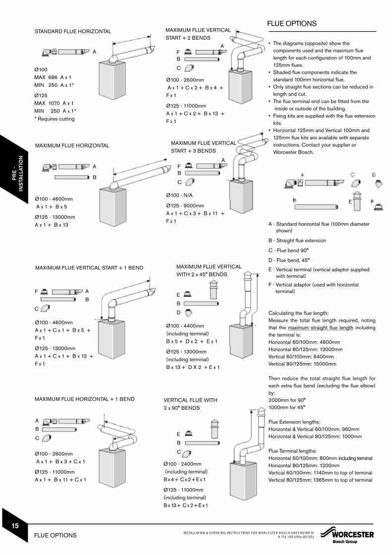
• The diagrams (opposite) show the components used and the maximum flue length for each configuration of 100mm and 125mm flues.
• Shaded flue components indicate the standard 100mm horizontal flue.
• Only straight flue sections can be reduced in length and cut.
• The flue terminal end can be fitted from theinside or outside of the building.
• Fixing kits are supplied with the flue extensionkits.
• Horizontal 125mm and Vertical 100mm and 125mm flue kits are available with separate instructions. Contact your supplier or Worcester Bosch.
A - Standard horizontal flue (100mm diameter shown)
B - Straight flue extension
C - Flue bend 90°
D - Flue bend, 45°
E - Vertical terminal (vertical adaptor supplied with terminal)
F - Vertical adaptor (used with horizontal terminal)
Calculating the flue length:Measure the total flue length required, notingthat the maximum straight flue length includingthe terminal is:Horizontal 60/100mm: 4600mmHorizontal 80/125mm: 13000mmVertical 60/100mm: 6400mmVertical 80/125mm: 15000mm
Then reduce the total straight flue length foreach extra flue bend (excluding the flue elbow)by:2000mm for 90°1000mm for 45°
Flue Extension lengths: Horizontal & Vertical 60/100mm: 960mmHorizontal & Vertical 80/125mm: 1000mm
Flue Terminal lengths:Horizontal 60/100mm: 800mm including terminalHorizontal 80/125mm: 1200mmVertical 60/100mm: 1140mm to top of terminalVertical 80/125mm: 1365mm to top of terminal
STANDARD FLUE HORIZONTAL
Ø100MAX 686 A x 1MIN 250 A x 1*
Ø125MAX 1070 A x 1MIN 250 A x 1** Requires cutting
MAXIMUM FLUE HORIZONTAL
Ø100 - 4600mmA x 1 + B x 5
Ø125 - 13000mmA x 1 + B x 13
MAXIMUM FLUE VERTICAL START + 1 BEND
Ø100 - 4600mmA x 1 + C x 1 + B x 5 +F x 1
Ø125 - 13000mmA x 1 + C x 1 + B x 13 +F x 1
Ø100 - 2600mmA x 1 + B x 3 + C x 1
Ø125 - 11000mmA x 1 + B x 11 + C x 1
MAXIMUM FLUE HORIZONTAL + 1 BEND
MAXIMUM FLUE VERTICAL START + 2 BENDS
Ø100 - 2600mmA x 1 + C x 2 + B x 4 +F x 1
Ø125 - 11000mmA x 1 + C x 2 + B x 13 +F x 1
Ø100 - N/A
Ø125 - 9000mmA x 1 + C x 3 + B x 11 +F x 1
MAXIMUM FLUE VERTICAL WITH 2 x 45° BENDS
Ø100 - 4400mm (including terminal)B x 5 + D x 2 + E x 1
Ø125 - 13000mm(including terminal)B x 13 + D X 2 + E x 1
Ø100 - 2400mm(including terminal)B x 4 + C x 2 + E x 1
Ø125 - 11000mm(including terminal)B x 13 + C x 2 + E x 1
VERTICAL FLUE WITH 2 x 90° BENDS
A
A
B
A
B
F
C
A
B
C
FB
C
A
FB
C
A
E
B
D
E
B
C
MAXIMUM FLUE VERTICAL START + 3 BENDS
FLUE OPTIONS INSTALLATION & SERVICING INSTRUCTIONS FOR WORCESTER BOSCH GREENSTAR Ri8 716 109 699a (05/05)
15

A - Straps
B - Outer carton
C - Base tray
D - Inner wrap and wall template
E - Wall mounting plate
F - Installer pack
G - Base Panel
H - 22mm pipes (2) (system flow and return)
IMPORTANT HANDLING INSTRUCTIONS• It is advised that two people are used to carry
the carton from the van to the point of delivery.• Once the carton has been delivered , the outer
carton is removed first. Care should be taken when releasing the straps. If a sharp impliment is used make sure the outer carton is not peirced and that the impliment is used in such away so that it may not cause personal injury. All sharp objects must be covered or the blade retracted after use and put away in a safe place. The wall mounting plate, the 2 X 22mm pipes and the Lit/Hardware pack are now removed making sure that no damage occurs tothe internal wrap which doubles as the Wall Template. Care should be taken when lifting theboiler from the base and the proper technique for safe lifting of any heavy object should be strictly observed.Additional requirements for roof space installation:
• The boiler should be first unpacked beforeascending ladder to loft space.
• Two sets of steps should be used.• Two people should share the lifting of the
boiler up to the loft hatch, where the boiler isentered into the loft space tilted and slid on its back into the loft.
Once the appl iance is removed from itspackaging check the contents against thepacking list.
Before installing appliance ensure system hasbeen cleaned as explained on page 8.
UNPACKING THE BOILER
LIFTING AND CARRYING PRECAUTIONS:• Lift only a manageable weight, or ask for
help. • When lifting or putting things down, bend
the knees, and keep the back straight and feet apart.
• Do not lift and twist at the same time. • Lift and carry objects close to the body
IIMPORTANT: All the previous Pre-Installation sections must be readand requirements met before starting boiler or flue installation.
E
F
NOTE:Cardboardinner wrap isalso the wall template.
NOTE: Carefully cut along perferated line torelease wall template.
A
B
C
D
C
D
G
H
UNPACKING THE BOILERINSTALLATION & SERVICING INSTRUCTIONS FOR WORCESTER BOSCH GREENSTAR Ri8 716 109 699a (05/05)
16
INS
TALL
ATIO
N

SAFETY:All relevant safety precautions must be undertaken.Protective clothing, footwear, gloves and safetygoggles must be worn as appropriate.
FIXING THE MOUNTING FRAME:• The boiler template shows the relative
positions of the flue and pipes to the boiler. Also clearances around the appliance.
Fix the template to the wall in the desired position ( A ).
Mark the clearance around the boiler and the position of gas and system pipes ( 2 ) and ( 3 ).
Drill 4 holes for the wall mounting plate through the template.
Drill 2 holes for bottom fixing screws. Drill hole for flue duct through the wall.
NOTE: The template has been sized to allow for minimum clearances of 5mm sides, 200mm base and 30mm above a Ø100 flue elbow.
REAR FLUE OUTLET• The drawing ( B ) opposite shows the boiler
template with the flue centre lines of both the 100mm and 125mm flue systems.
Mark centreline of flue to be used ( 1 ).• If a Ø100mm diameter flue is to be used,
a125mm diameter hole is required. However, ifusing the weather sealing collar by pushing it through from inside the property, then a 150mm diameter hole is required to accommodate this.
• The terminal section of the 100mm flue has an inbuilt 3° angle.If extensions are to be added then the completeflue must rise at an angle of 3°.
• The 125mm Ø flue system will require the flue to rise at an angle of 3°.
Drill hole using a core drill or similar.
SIDE OUTLET: Mark from the centre line of the wall template
to the wall which the flue will pass through ( 4 ).
Allow for a rise of 52mm per metre length of flue, to give a 3° angle.
Clear any debris from the site.
CAUTION: Ensure there are no pipes,electric cables, damp proof courses orother hazards before drilling.
X 6
X 6
10mm Ø
WALL MOUNTING PLATE
FLUE OPENING
127mm
WALL MOUNTING PLATE FLUE OPENING INSTALLATION & SERVICING INSTRUCTIONS FOR WORCESTER BOSCH GREENSTAR Ri8 716 109 699a (05/05)
17
INS
TALL
ATIO
NC
OM
MIS
SIO
NIN
G
A
B

1
2
3
4
B
A
OUTER CASE REMOVAL
REMOVING OUTER CASE1. Undo and remove 2 screws (A) securing
boiler casing at the top of the appliance.2. Undo the 2 captive screws (B) securing
boiler casing at the bottom of the appliance.3. Pull case upwards.4. Remove cardboard packing piece from
appliance. With the outer case removed the
appliance is suitable for a 1 man lift (<25kg).
OUTER CASE REMOVALINSTALLATION & SERVICING INSTRUCTIONS FOR WORCESTER BOSCH GREENSTAR Ri8 716 109 699a (05/05)
18
INS
TALL
ATIO
N
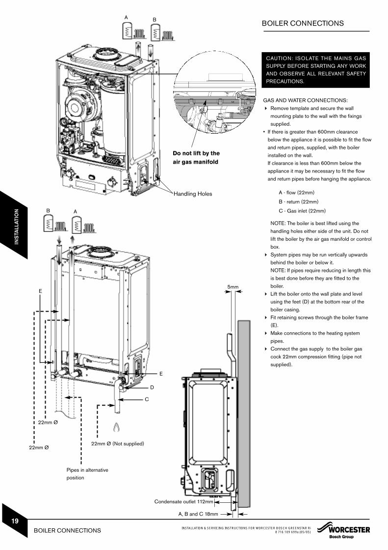
GAS AND WATER CONNECTIONS: Remove template and secure the wall
mounting plate to the wall with the fixings supplied.
• If there is greater than 600mm clearance below the appliance it is possible to fit the flow and return pipes, supplied, with the boiler installed on the wall.If clearance is less than 600mm below the appliance it may be necessary to fit the flow and return pipes before hanging the appliance.
A - flow (22mm)
B - return (22mm)
C - Gas inlet (22mm)
NOTE: The boiler is best lifted using the handling holes either side of the unit. Do not lift the boiler by the air gas manifold or control box.
System pipes may be run vertically upwards behind the boiler or below it.NOTE: If pipes require reducing in length this is best done before they are fitted to the boiler.
Lift the boiler onto the wall plate and level using the feet (D) at the bottom rear of the boiler casing.
Fit retaining screws through the boiler frame (E).
Make connections to the heating system pipes.
Connect the gas supply to the boiler gas cock 22mm compression fitting (pipe not supplied).
BOILER CONNECTIONS
CAUTION: ISOLATE THE MAINS GASSUPPLY BEFORE STARTING ANY WORKAND OBSERVE ALL RELEVANT SAFETYPRECAUTIONS.
22mm Ø
22mm Ø
22mm Ø (Not supplied)
5mm
Pipes in alternativeposition
AB
A B
D
E
C
E
BOILER CONNECTIONS INSTALLATION & SERVICING INSTRUCTIONS FOR WORCESTER BOSCH GREENSTAR Ri8 716 109 699a (05/05)
19
INS
TALL
ATIO
N
Handling Holes
Do not lift by theair gas manifold
Condensate outlet 112mm
A, B and C 18mm

FLUE INSTALLATION
HORIZONTAL FLUE(60/100mm diameter)For vertical flues and 80/125mm horizontal flues,please refer to separate instructions supplie withthe flue kits.NOTE: to ease the assembly of flue components,apply silicone lubricant to sealing surfaces.The instructions for the 60/100mm diameter flueare shown below.
MEASURING THE FLUE (Standard Flue): Measure from the outside wall to the centre
line of the flue turret. Subtract 93mm from the length L to give
the correct dimension to the flue elbow connection.
The terminal section should be cut to this dimension, however it must not be shorter than 250mm.
After cutting the end must be square and free from burrs to prevent damage to the flue seals.
Edge ofcase 195mm
WALL
127mm
(250mm min)
FlueClampTurret
FLUE INSTALLATIONINSTALLATION & SERVICING INSTRUCTIONS FOR WORCESTER BOSCH GREENSTAR Ri8 716 109 699a (05/05)
20
INS
TALL
ATIO
N
93mm
FLUE INSTALLATION INSTALLATION & SERVICING INSTRUCTIONS FOR WORCESTER BOSCH GREENSTAR Ri8 716 109 699a (05/05)
21
INS
TALL
ATIO
NFLUE INSTALLATION
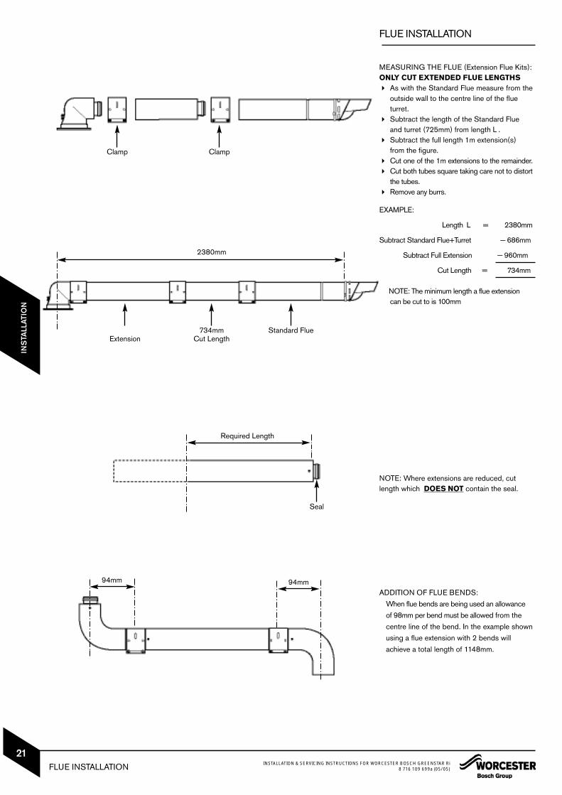
MEASURING THE FLUE (Extension Flue Kits):ONLY CUT EXTENDED FLUE LENGTHS As with the Standard Flue measure from the
outside wall to the centre line of the flue turret.
Subtract the length of the Standard Flue and turret (725mm) from length L .
Subtract the full length 1m extension(s) from the figure.
Cut one of the 1m extensions to the remainder. Cut both tubes square taking care not to distort
the tubes. Remove any burrs.
EXAMPLE:
Length L = 2380mm
Subtract Standard Flue+Turret — 686mm
Subtract Full Extension — 960mm
Cut Length = 734mm
NOTE: The minimum length a flue extension can be cut to is 100mm
NOTE: Where extensions are reduced, cutlength which DOES NOT contain the seal.
ADDITION OF FLUE BENDS:When flue bends are being used an allowance of 98mm per bend must be allowed from the centre line of the bend. In the example shownusing a flue extension with 2 bends will achieve a total length of 1148mm.
Clamp Clamp
Extension734mm
Cut LengthStandard Flue
Seal
2380mm
Required Length
94mm 94mm

A B
C
D
E
A - Standard Flue
B - Internal Wall Seal
C - External Wall Seal
D - Clamping Plate
E - Extension Duct
Flat at back
FLUE INSTALLATION
ASSEMBLING THE FLUE1 Slide inner collar (B) onto terminal (A)2 Additional extensions or bends:
Push fit all extensions/bends/terminal together and secure connections with clamps (D). The slope of the terminal outlet must face downwards.
FITTING THE FLUE3 Fit the terminal (A) through the flue opening
in the wall, exposing the plastic outlet section to the outside and fit the outer flue collar ( C ) over the notches to secure.
4 Assemble elbow to boiler using the three screws (see below).Note: Screws are in boiler not in flue kit.
FITTING THE ELBOW:• Flue elbow should push directly down and
not be twisted into correct position. Remove the 3 inner flue tube retaining
screws. The inner tube will be held in place in the appliance.
Fit turret onto applliance and retain with the three removed screws.NOTE: The clamping plate flat should be at the rear of the appliance.
ADDITIONAL NOTES AND REMINDERS:• Ensure that all cut lengths are square and
free from burrs. • The flue, when assembled, is fully sealed and
components are pushed home.• The flue is set at an angle 3° or 52mm per
1m length.
FLUE INSTALLATIONINSTALLATION & SERVICING INSTRUCTIONS FOR WORCESTER BOSCH GREENSTAR Ri8 716 109 699a (05/05)
22
INS
TALL
ATIO
N
This screw shouldbe fitted last foreasier installation
This screw shouldbe fitted last foreasier installation
Apply siliconegrease toseal
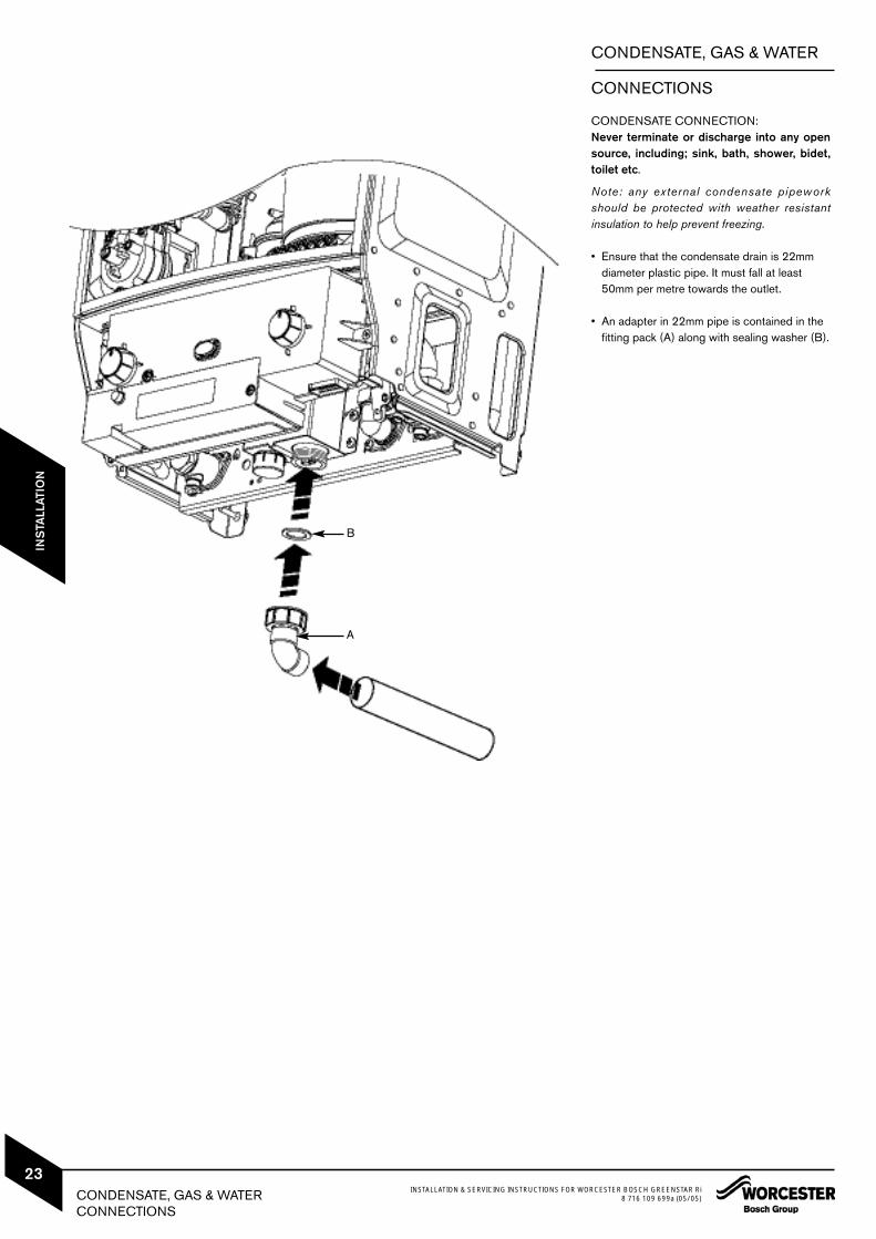
CONDENSATE CONNECTION:Never terminate or discharge into any opensource, including; sink, bath, shower, bidet,toilet etc.
Note: any external condensate pipeworkshould be protected with weather resistantinsulation to help prevent freezing.
• Ensure that the condensate drain is 22mm diameter plastic pipe. It must fall at least 50mm per metre towards the outlet.
• An adapter in 22mm pipe is contained in the fitting pack (A) along with sealing washer (B).
CONDENSATE, GAS & WATER
CONNECTIONS
A
B
CONDENSATE, GAS & WATERCONNECTIONS
INSTALLATION & SERVICING INSTRUCTIONS FOR WORCESTER BOSCH GREENSTAR Ri8 716 109 699a (05/05)
23
INS
TALL
ATIO
N

ELECTRICS
CAUTION: ISOLATE THE MAINS ELECTRICITY SUPPLY BEFORE STARTINGANY WORK AND OBSERVE ALL RELEVANT SAFETY PRECAUTIONS
Note: Mains supply to the boiler and systemwiring centre must be through a commonfused double pole isolator situated adjacentto the appliance. The isolator must have acontact separation of 3mm minimum in allpoles. A switched live signal should be wiredto the boiler from the wiring centre.
Access to electric control panel:1 Remove boiler casing to access control panel.2 Unscrew the three screws (A) in the control
panel and pull off the connections cover (B).3 Unclip cable clamp (C).4 Cut off the tapered cable entry to fit cable
diameter required.5 Turn cable retaining screw (D) anti-clock-wise6 Run cable over the main crossbar and
through the cable clamp (C), ensure there isample cable to reach the connectors.
7 Turn cable clamping screw (D) clockwise to secure cable and replace clamp (C) into control panel.
8 Mains power 230v connection (ST1): Separate wires from cable end and strip to
6mm Connect LIVE wire to terminal (L) Connect NEUTRAL wire to the terminal (N) Connect EARTH wire to the connector (E)
9A External Pump (ST2): Connect NEUTRAL wire to terminal (Np) Connect LIVE wire to terminal (Lp) Connect EARTH wire to earth bracket (E)
9B Boiler Demand Live (from external wiring centre) (ST2):
Connect DEMAND LIVE wire to terminal (LR).
NOTE: THE SYSTEM PUMP MUST BECONNECTED TO THE APPLIANCE CON-TROL FOR THE PUMP OVER-RUN FACILITY.
Refit electric control panel covers: Refit panel (B) and secure with screws. Locate lugs at top edge of panel (A) and
clip in at base.
9A
9B
ELECTRICSINSTALLATION & SERVICING INSTRUCTIONS FOR WORCESTER BOSCH GREENSTAR Ri8 716 109 699a (05/05)
24
INS
TALL
ATIO
N

POSITION OF WIRED
COMPONENTS
POSITION OF WIRED COMPONENTS INSTALLATION & SERVICING INSTRUCTIONS FOR WORCESTER BOSCH GREENSTAR Ri8 716 109 699a (05/05)
25
INS
TALL
ATIO
NC
OM
MIS
SIO
NIN
G
PRE-COMMISSIONING
CHECKS
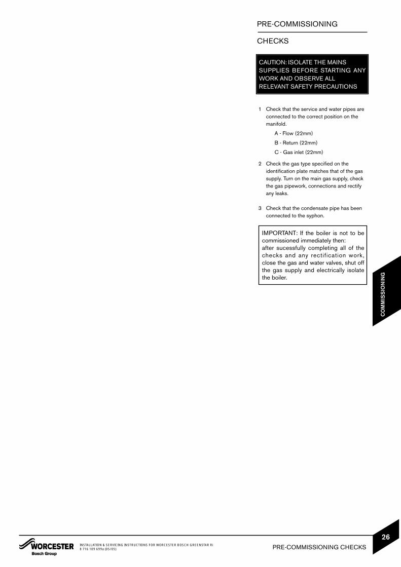
CAUTION: ISOLATE THE MAINS SUPPLIES BEFORE STARTING ANYWORK AND OBSERVE ALL RELEVANT SAFETY PRECAUTIONS
1 Check that the service and water pipes are connected to the correct position on the manifold.
A - Flow (22mm)
B - Return (22mm)
C - Gas inlet (22mm)
2 Check the gas type specified on the identification plate matches that of the gas supply. Turn on the main gas supply, check the gas pipework, connections and rectify any leaks.
3 Check that the condensate pipe has been connected to the syphon.
IMPORTANT: If the boiler is not to becommissioned immediately then:after sucessfully completing all of thechecks and any rectification work,close the gas and water valves, shut offthe gas supply and electrically isolatethe boiler.
PRE-COMMISSIONING CHECKSINSTALLATION & SERVICING INSTRUCTIONS FOR WORCESTER BOSCH GREENSTAR Ri8 716 109 699a (05/05)
26
CO
MM
ISS
ION
ING

FILLING THE SYSTEM
1 Ensure all system and boiler drain points areclosed.
2 If connected to an open vented system turn on the water supply to system header tank and allow to fill the system.
3 For sealed systems fill the system using a WRAS approved filling loop to a pressure of1 bar.
4 Vent (A) any air from the boiler heat exchanger using a suitable container to collect any water. Ensure tube outlet (B) is directed away from the fan or any other electrical component to prevent any water damage. Also place a suitable cover over the fan to prevent any spillage of water onto electrical connections. Ensure the cover is removed after venting.
5 Vent all radiators and primary side of the hotwater cylinder.
GAS SUPPLY Open gas cock on the boiler and purge the
gas supply to the boiler ensuring that the room is well ventilated.
Test for gas supply for soundness as described in BS 6891.
1
4
A
B
FILLING THE SYSTEM INSTALLATION & SERVICING INSTRUCTIONS FOR WORCESTER BOSCH GREENSTAR Ri8 716 109 699a (05/05)
27
CO
MM
ISS
ION
ING

Switching the appliance on/off:1 Turn on mains power supply
Turn on any external controlsSet the thermostatic radiator controls to maximum temperatureSet the clock/programmer to continuouslyON and the room thermostat to maximumtemperature
2 Turn control (A) from 0 (off position) to I (on position) the power on indicator (B) illuminates BLUE.
3 Turn the boiler thermostat control (C) to maximum. The burner on indicator (D) illuminates GREEN.
4 If the boiler fails to light and the boiler goes to flame lock-out the BLUE power indicator (B) will flash twice a second. To reset the lockout turn the boiler thermostat control to minimum, then past minimum where the control will click at reset position, wait 2 seconds then turn to maximum. The boiler will be reset.
STARTING THE APPLIANCE
IMPORTANT: Never run the appliancewhen the appliance/system is empty orpartially filled.
AD
BC
MIN
MAXRESET
CAUTION: DO NOT PRESS POWERINDICATOR (B) TO RESET BOILER.
STARTING THE APPLIANCEINSTALLATION & SERVICING INSTRUCTIONS FOR WORCESTER BOSCH GREENSTAR Ri8 716 109 699a (05/05)
28
CO
MM
ISS
ION
ING

WATER TREATMENT
ENSURE THAT THE SYSTEM HAS BEENCLEANED AS ON PAGE 7 OF THESEINSTRUCTIONS.
FLUSHING (Central Heating):1 Switch off the boiler (A). If connected to an
open vented system turn OFF the water supply to the system header tank
Open all drain cocks (B) and drain the system (C) while the appliance is hot.
2 Close drain cocks (D) and add a suitable flushing agent (E) at the correct strength forthe system condition in accordance with themanufacturer's instructions.
3 Run the boiler/system at normal operatingtemperature (F) for the time stated by the manufacturer of the flushing agent (G).
4 Drain (H) and thoroughly flush the system toremove the flushing agent and debris ( I ).
INHIBITOR (Central Heating):5 Check drain cocks are closed ( J ) and all
radiator valves are open (K) before adding a suitable*inhibitor (or combined inhibitor/anti-freeze if the system is exposed to freezing conditions) to the heating system water (L) inaccordance with the manufacturers instructions.
6 If connected to an open vent system turn onthe water supply to the system header tank and allow to fill the system.If connected to a sealed system fill via a WRAS approved filling loop to between 1 and 2 bar.
7 Vent all radiators; retighten vents when complete (M). Vent any air from the boiler heat exchanger using a suitable container tocollect any water (N).
Ensure tube outlet (0) is directed away from the fan or any other electrical component to prevent damage.
8 Vent all radiators and the primary side of thehot water tank (P).
For sealed systems re-pressurise if necessary.
Turn pressure relief valve anti-clockwise untilthe pressure is 1bar (Q).
Set all controls to maximum (R).
Record the date when the inhibitor was added to the system on the guarantee card.
NOTE: The concentration level of inhibitor inthe system should be checked every 12months or sooner if system content is lost.
The addition of sealing agents to the systemwater is not recommended as this can causeproblems with deposits left in the heatexchanger.
IMPORTANT: Debris from the systemcan damage the boiler and reduceefficiency. Failure to comply with theguidelines for the use of watertreatment with the appliance willinvalidate the appliance warranty.
* compatible with aluminium. The pHvalue of the system water must beless than 8 or the appliance guaranteewill be invalidated.
1
2
3
4
5
7
8
A
B
C
D
E
FG
H
I
J
K
L
M
N
O
P
Q
R
KEYValve
FlushingAgent
Inhibitor
WATER TREATMENT INSTALLATION & SERVICING INSTRUCTIONS FOR WORCESTER BOSCH GREENSTAR Ri8 716 109 699a (05/05)
29
CO
MM
ISS
ION
ING

COMMISSIONING
THE COMBUSTION FOR THE APPLIANCEIS FACTORY SET. NO ADJUSTMENT IS REQUIRED IF THEGAS INLET PRESSURE IS CORRECT.
CHECKING GAS INLET PRESSURE:The inlet pressure to the appliance must be checked using the following proceedure:
SETTING THE BOILER TO MAXIMUM:1 Remove the three screws (A) retaining the
control cover.• Clipped inside the cover is a plastic tool
used to change the position of the mode switch (B).
2 Using the tool set the mode switch to maximum.
• The power indicator will flash and the boiler will stay in this mode for 15 minutes if no further change is made to the switch.
MEASURING THE INLET PRESSURE:3 Slacken the screw in the inlet pressure test
point and connect a manometer. Measure the pressure with the boiler
running at maximum. Check the gas supply working pressure at
the gas valve inlet point is no less than:N.G. 18.5 mbarL.P.G. 37 mbar
Ensure inlet pressure is satisfactory with all other gas appliances working.
The gas rate should be measured at the gasmeter after 10 minutes operation at maximum.See technical data section at the front of this manual.
If pressure is satisfactory turn the mode switch (B) to norm and remove the manometer.
Re-seal the screw in the gas inlet pressure test point.
Replace controls cover. Note: This boiler is designed with differential of20°C across the heating system.
IMPORTANT: Do not continuecommissioning until the correctgas pressure is achieved.
1
A
B
B
2
3
Inlet Test Nipple
NORM
MAX
MIN
COMMISSIONINGINSTALLATION & SERVICING INSTRUCTIONS FOR WORCESTER BOSCH GREENSTAR Ri8 716 109 699a (05/05)
30
CO
MM
ISS
ION
ING

FINISHING COMMISSIONING
The boiler has been factory set, so thereshould be no need to adjust any controls.
1 Install bottom panel.A The cut out in the bottom panel fits easily
over the syphon elbow and outlet, however care should be taken not to disturb any sealed components.
B Hook the lip at the back of the bottom panelover the angled edge at the base of theconnections manifold.
C Gently push up into position. Secure in place with the two screws
supplied (D).
2 Replace outer casing. Replace outer casing making sure that the
securing points are properly located. Replace top two screws (E). Retighten bottom two screws (F).
HANDOVER: Complete the Benchmark checklist.NOTE: The Benchmark Checklist can befound at the rear of these instructions. Set up the controls and show the user how
to operate all the controls shown in the UserGuide.
If the appliance is unused and exposed to freezing conditions; shut off all the mains supplies and drain the system and boiler.
1
E
A
B
C
D
F
FINISHING COMMISSIONING INSTALLATION & SERVICING INSTRUCTIONS FOR WORCESTER BOSCH GREENSTAR Ri8 716 109 699a (05/05)
31
CO
MM
ISS
ION
ING

INSPECTION AND SERVICE
To ensure the continued efficient operation
of the appliance it must be checked at
regular intervals.
The frequency of servicing will depend upon
the particular installation conditions and
usage however, an annual service is
recommended .
The extent of the service required by the
appliance is determined by the operating
condition of the appliance when tested by
fully qualified engineers.
The service interval record sheet at the rear
of these instructions must be completed
after each service.
Inspection1 Check that the terminal and the terminal
guard, if fitted, are clear and undamaged.
2 If the appliance is in a compartment or
cupboard check that the specified service
space around the appliance is clear. Refer to
page 11 for information.
3 Check all the joints and connections in the
system and remake any that show signs of
leakage. Refill and re-pressurise if
applicable as described in Commissioning.
Operate the appliance and take note of any
irregularities.
Refer to Fault Finding for rectification
procedures.
IMPORTANT: Any service workmust be carried out by competentregistered engineers such asBritish Gas or Corgi registered personnel.
CAUTION: TURN OFF THE GAS SUPPLY AND ISOLATE THE MAINSSUPPLIES BEFORE STARTING ANY WORK AND OBSERVE ALLRELEVANT SAFETY PRECAUTIONS.
IMPORTANT: AFTER REPLACEMENT OF ANY COMPONENTS ALWAYSCHECK FOR GAS SOUNDNESS WHERE RELEVANT AND CARRY OUTFUNCTIONAL CHECKS AS DESCRIBED IN COMMISSIONING.ANY O-RING OR GASKET THAT APPEARS DAMAGED MUST BEREPLACED.
1
2
3
INSPECTION AND SERVICEINSTALLATION & SERVICING INSTRUCTIONS FOR WORCESTER BOSCH GREENSTAR Ri8 716 109 699a (05/05)
32
SE
RVI
CIN
G&
SPA
RE
S

INSPECTION AND SERVICE
Component Access
1. Removing outer case1.1a Undo and remove 2 screws (A) securing
boiler casing at the top of the appliance.1.1b Undo but do not remove the 2 screws
(B) securing boiler casing at the bottom of the appliance.
1.2 Pull case forward and remove. It is necessary to remove bottom tray if
action 2 to 2.2 is done, this is retained by two screws at the front and hooks over the bottom frame work of the boiler.
2. Adjusting boiler control to service position
2.1 Remove two screws (D) securing control.2.2 Hang control on two lugs (E) on boiler
framework.
31
A
1.1a 1.1b 1.2
B
2.1
2.2
D
E
INSPECTION AND SERVICE INSTALLATION & SERVICING INSTRUCTIONS FOR WORCESTER BOSCH GREENSTAR Ri8 716 109 699a (05/05)
33
SE
RVI
CIN
G&
SPA
RE
S

INSPECTION AND SERVICE
Primary Heat ExchangerThere is a special accessory kit availble
specifically designed for cleaning the
heat exchanger. If required order
7 716 192 312.
3 Check fan pressure at the test point next to
the fan using an electronic manometer The boiler must be run at maximum output.
Pressure will read negative and be greaterthan:
NG LPG
12kW - 3.6 mbar - 3.9 mbar
15kW - 5.5 mbar - 5.8 mbar
18kW - 7.4 mbar - 8.0 mbar
24kW - 3.1 mbar - 4.1 mbar
Pressures measured below these figures will indicate that the heat exchanger will require cleaning
Setting Boiler to Maximum.1 Remove the three screws (A) retaining the
control cover.
Clipped inside the cover is a plastic tool
used to change the mode switch setting
(B).
2 Using the tool set the mode switch to
maximum.
The power indicator will flash and the boiler
will stay in this mode for 15 minutes if no
further change is made to the switch.
3 Pull cover off and connect manometer to
the fan pressure test point.
Pressure will read negative and be greater
than:
NG LPG
12kW - 3.6 mbar - 3.9 mbar
15kW - 5.5 mbar - 5.8 mbar
18kW - 7.4 mbar - 8.0 mbar
24kW - 3.1 mbar - 4.1 mbar
After measurement replace test point cover
and return mode switch to normal.
Replace controls cover.
1
A
B
B
2
3
INSPECTION AND SERVICEINSTALLATION & SERVICING INSTRUCTIONS FOR WORCESTER BOSCH GREENSTAR Ri8 716 109 699a (05/05)
34
SE
RVI
CIN
G&
SPA
RE
S

INSPECTION AND SERVICE
1
A
B
3
2
C
D
INSPECTION AND SERVICE INSTALLATION & SERVICING INSTRUCTIONS FOR WORCESTER BOSCH GREENSTAR Ri8 716 109 699a (05/05)
35
SE
RVI
CIN
G&
SPA
RE
S
To Clean the Heat Exchanger1 With outer case and base panel removed and
the power isolated from the appliance, remove the cover panel (A) by removing the retaining screw (B).
2 Remove clip (C) from gas valve outlet. Pull gas adjustment assembly (D) free from
the plastic connection on the gas valve. Pull gas adjustment assembly (D) forward to
clear case.
Removing Syphon3.1 Undo plastic nut (E) on the syphon outlet.
Drop condensate tube away from syphon.3.2 Remove two screws (F).3.3 Remove syphon
Syphon The syphon body is transparent so contents
can be examined for any blockage. If necessary flush with clean water.
COMBUSTION TESTING MUST BE CARRIEDOUT BY A COMPETENT PERSON. IT MUSTNOT BE ATTEMPTED UNLESS THE PERSONCARRYING OUT THE COMBUSTION CHECKI S E Q U I P P E D W ITH A C O M B U STI O NANALYSER CONFORMING TO BS 7927 ANDIS COMPETENT IN IT’S USE.
IMPORTANT: IF THE JOINTBETWEEN THE AIR/GAS MANIFOLDAND THE HEAT EXCHANGER ISDISTURBED THE SEALING GASKETMUST BE REPLACED.
F
E

INSPECTION AND SERVICE
Remove electrical connector from fan. Remove electrical connector from fan.4 Undo and remove securing nut (E) from the
top of the heat exchanger.5 Remove stainless steel viewing mirror (F).6 Rotate fan and air/gas manifold assembly (G)
around the top of the heat exchanger until it stops at the lug.
Lift up assembly and remove from boiler.7 Disconnect spark electrode and flame sensor
connections (J). Remove clamping plate (K). Remove spark/flame electrode assembly
from boiler. Remove seal from the top of the heat
exchanger
4
5
E
F
6
G
7
K
J
SE
RVI
CIN
G&
SPA
RE
S
INSPECTION AND SERVICEINSTALLATION & SERVICING INSTRUCTIONS FOR WORCESTER BOSCH GREENSTAR Ri8 716 109 699a (05/05)
36

INSPECTION AND SERVICE
8
L
M
N
0
P
Q
R
INSPECTION AND SERVICE INSTALLATION & SERVICING INSTRUCTIONS FOR WORCESTER BOSCH GREENSTAR Ri8 716 109 699a (05/05)
37
SE
RVI
CIN
G&
SPA
RE
S
8 Remove burner (L). Remove top baffle (M). Remove baffle (N). Remove the two hexagon headed screws (O)
retaining the access cover (P) on the sump. Access the heat exchanger flue ways by
inserting the cleaning brush (7 716 192 312)through the top access hole in the casing (Q).
Clean heat exchanger flue ways (R) using thecleaning brush (7 716 192 312) removing any debris from the access point in the sump.
Clean around sealing surface on sump and replace access cover (P). Using a suitable container to collect water from syphon connection at the base of the boiler flush heat exchanger with water.
Re-assemble ensuring that the lower baffle (N) and the top baffle (M) are refitted correctly.
When re-fitting the burner ensure that it fits centrally within the heat exchanger and location tabs are situated in location holes.
Ensure seal is replaced with new seal and is correctly fitted.
Check the syphon unit for blockage before refitting to boiler.
Reassemble and check combustion as stated in the gas conversion section.NOTE: To show the heat exchanger more clearly it has been shown external to the appliance
THE BAFFLES (N) AND (M) MUSTBE REFITTED INTO THE HEATEXCHANGER AS SHOWN IN 9.FAILURE TO DO SO MAY RESULTIN DAMAGE TO THE BOILER
IMPORTANT: IF THE JOINTBETWEEN THE AIR/GAS MANIFOLDAND THE HEAT EXCHANGER ISDISTURBED THE SEALING GASKETMUST BE REPLACED.
Smalltab

1.1
1.2
A
B
1.1 Remove 3 screws (A) and cover (B) from control box.
Clipped inside the cover is a plastic tool
used to change the mode switch setting.
Re-connect mains electrical supply.
1.2 Using the tool set the mode switch to
maximum.
The power indicator will flash and the boiler
will stay in this mode for 15 minutes if no
further change is made to the switch.
MAX
NORMMIN
THE BOILER IS FACTORY SET. ADJUSTMENTOF AIR / GAS RATIO IS ONLY REQUIRED IFSTATED IN THE SERVICING OR REPLACEMENTPARTS SECTION OF THE MAIN INSTRUCTIONS
SETTING THE GAS / AIR RATIO
ISOLATE MAINS ELECTRICALSUPPLY AND REMOVE OUTERCASE AS SHOWN IN THEINSTALLATION, COMMISSIONING &SERVICING INSTRUCTIONS
SETTING THE GAS / AIR RATIOINSTALLATION & SERVICING INSTRUCTIONS FOR WORCESTER BOSCH GREENSTAR Ri8 716 109 699a (05/05)
38
SE
RVI
CIN
G&
SPA
RE
S

1.4 Remove covers from the air/gas outlet
adjuster and gas valve adjuster. Connect
manometer to inlet pressure point on the
gas valve.
The boiler should be run for 10 minutes before
taking a CO2 measurement and compared
with the figure in the table below.
1.5 If required, use a flat blade screwdriver to
set the CO2 (A) to the figure in the table below.
The CO must also be checked and be below
200ppm (0.002 ratio)
Measure the inlet pressure, it should be no
less than 18.5mb for natural gas and 37mb
for LPG.
1.6 Set the mode switch to minimum
1.7 Measure the CO2, it should now be at the
figure for minimum output. If not adjust (B)
on the gas valve until correct.
Return to maximum and re-check the CO2. If
correct set the mode switch to normal and
isolate mains supply.
Remove manometer and re-seal inlet pressure
point on gas valve.
Re-assemble and refit boiler case.
Re-connect mains electrical supply and
check boiler operation as stated in the
commissioning section of the Installation,
commissioning & Servicing Instructions.
1.4
1.5
1.7
1.6
Inlet Test Nipple
+ –
B
A
+–
Gas type
CO2 settings for Greenstar Ri
Natural gas
LPG
9.8% +/– 0.2
11.0% +/– 0.2
9.2% +/– 0.2
10.5% +/– 0.2
CO2 settingmaximum
CO2 settingminimum
MAX
NORMMIN
SETTING THE GAS / AIR RATIO INSTALLATION & SERVICING INSTRUCTIONS FOR WORCESTER BOSCH GREENSTAR Ri8 716 109 699a (05/05)
39
SETTING THE GAS / AIR RATIO
THE SETTING OF THE GAS RATIO MUST BECARRIED OUT BY A COMPETENT PERSON.SETTING OF THE GAS RATIO MUST NOT BEATTE M PTE D U N LE S S TH E P E R S O NC AR RYI N G O UT TH E C O NVE R S I O N I SEQUIPPED WITH A COMBUSTION ANALYSERC O N F O R M I N G TO B S 7927 AN D I SCOMPETENT IN ITS USE.
Please note: The flue gas test point can beaccessed on the appliance flue elbow by removing cap C
C
SE
RVI
CIN
G&
SPA
RE
S

CAUTION: TURN OFF THE GAS SUPPLY AND ISOLATE THE MAINSSUPPLIES BEFORE STARTING ANY WORK AND OBSERVE ALLRELEVANT SAFETY PRECAUTIONS.
IMPORTANT: AFTER REPLACEMENT OF ANY COMPONENTS ALWAYSCHECK FOR GAS SOUNDNESS WHERE RELEVANT AND CARRY OUTFUNCTIONAL CHECKS AS DESCRIBED IN COMMISSIONING.ANY O-RING OR GASKET THAT APPEARS DAMAGED MUST BEREPLACED.
REPLACEMENT OF PARTS
1. Removing outer case1.1 Undo 4 screws (A) securing boiler casing.1.2 Pull case forward and remove. If it is necessary to remove bottom tray, this
is retained by two screws (B) at the front and hooks over the bottom frame work of the boiler.
2. Primary sensor Remove electrical connection (C) by pulling
upwards. Squeeze retaining clip on plastic moulding (D) and pull sensor (E) upwards until clear of pocket in heat exchanger.
Coat new sensor with heat conductive paste and replace.
3. Overheat thermostat Remove two electrical connectors from
thermostat. Slacken and remove fixing screw and
thermostat. When replacing ensure thermostat sits
correctly on surface of the casing with the left hand side of thermostat siting up against the shoulder (F).
Note: It is essential that the mating surface ofthe thermostat is coated with heat conductive paste.
4. Flue limit thermostat Remove electrical connections. Unscrew thermostat from flue.
The following components can bereplaced with the outer caseremoved:Primary sensorOverheat thermostatFlue limit thermostat
A
1.1a 1.1b 1.2
A
B
REPLACEMENT OF PARTSINSTALLATION & SERVICING INSTRUCTIONS FOR WORCESTER BOSCH GREENSTAR Ri8 716 109 699a (05/05)
40
SE
RVI
CIN
G&
SPA
RE
S
2C
ED
3
4
F

REPLACEMENT OF PARTS
5. Moving boiler control to serviceposition5.1 Remove two screws (A) securing control.5.2 Hang control on two lugs (B) on boiler
framework.
6. Gas valve Isolate gas supply at boiler gas cock.6.1 Remove wire clip from gas valve outlet then
pull gas adjustment assembly free from plastic connector and pull forward clear of case.
6.2 Undo bottom gas connection to gas valve.6.3 Undo two securing screws (C) on the
underside of casing. Pull valve up and forward out of boiler. Disconnect electrical connections. Replace valve with new seals and check for
gas soundness.
7. Gas adjuster Isolate gas supply at boiler gas cock and
repeat step 6.1 above. Twist retaining clip (D) to release then
remove clip and tube. Refit new adjuster and secure with clip.
Note: The valve will require setting, followprocedure “Setting the gas/air ratio”.
8. Syphon8.1 Undo plastic nut (E) on the syphon outlet.
Drop condensate tube away from syphon.8.2 Remove two screws (F) retaining the bracket.8.3 Rotate syphon 90° to the left and remove.
E
The following components requirethe control to be moved in to theservice position and the bottomtray removed:Gas valveSyphonPCB fuseTransformer
5.1 5.2
A
6.2
6.3
6.1
7
8.38.28.1
B
D
F
C
REPLACEMENT OF PARTS INSTALLATION & SERVICING INSTRUCTIONS FOR WORCESTER BOSCH GREENSTAR Ri8 716 109 699a (05/05)
41
SE
RVI
CIN
G&
SPA
RE
S

REPLACEMENT OF PARTS
9. Access to boiler control components Move control to the service position. Remove 3 screws (A) and remove cover
from control.
10. PCB fuse Remove fuse in plastic housing (B) from the
PCB and replace. There is a spare fuse clipped into the cover.
11.Transformer / PCB Disconnect all electrical connections from
the control. Remove 4 screws (C) retaining the rear
panel of the control and remove panel.
IMPORTANT: ENSURE CODE PLUG IS RE-FITTED TO THE NEWCONTROL. IF THIS IS NOT DONETHE BOILER WLL INDICATE ERROR AND WILL NOT FUNCTION.
9
10
11
A
B
C
C
REPLACEMENT OF PARTSINSTALLATION & SERVICING INSTRUCTIONS FOR WORCESTER BOSCH GREENSTAR Ri8 716 109 699a (05/05)
42
SE
RVI
CIN
G&
SPA
RE
S

REPLACEMENT OF PARTS
12. Air / gas manifold and fanassembly Remove electrical connector from fan. Remove wire clip from gas valve outlet then
pull gas adjustment assembly free from plasticconnector and pull clear of case. See 6.1.
12.1 Undo and remove securing nut (A) from thetop of the heat exchanger.
12.2 Remove stainless steel viewing mirror (B).12.3 Rotate fan and air/gas manifold assembly
(shaded) around the top of the heat exchanger until the lug on the air/gas manifold is visible.
Lift up assembly and remove from boiler.
13. Pressure switch13.1 Remove electrical connections (C).13.2 Slacken top retaining screw and remove
bottom screw. (D).13.3 Remove tube (E).13.4 Remove 2 screws (F) retaining pressure
switch to bracket. Refit new pressure switch to bracket.
The following components requirethe air / gas manifold and fanassembly to be removed:Pressure switchFanElectrode assemblyBurnerHeat exchanger
12.1
12.2
13.4
13.313.213.1
A
B
CD
E
F
12.3
IMPORTANT: ENSURE TUBE ISREFITTED TO PRESSURE SWITCH
REPLACEMENT OF PARTS INSTALLATION & SERVICING INSTRUCTIONS FOR WORCESTER BOSCH GREENSTAR Ri8 716 109 699a (05/05)
43
SE
RVI
CIN
G&
SPA
RE
S
IMPORTANT: IF THE JOINTBETWEEN THE AIR/GAS MANIFOLDAND THE HEAT EXCHANGER ISDISTURBED THE SEALING GASKETMUST BE REPLACED.
REPLACEMENT OF PARTS
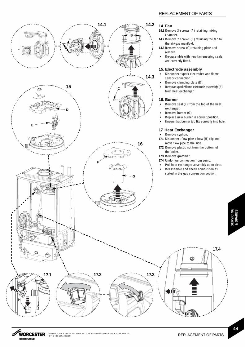
14. Fan14.1 Remove 3 screws (A) retaining mixing
chamber.14.2 Remove 2 screws (B) retaining the fan to
the air/gas manifold.14.3 Remove screw (C) retaining plate and
remove. Re-assemble with new fan ensuring seals
are correctly fitted.
15. Electrode assembly Disconnect spark electrodes and flame
sensor connection. Remove clamping plate (D). Remove spark/flame electrode assembly (E)
from heat exchanger.
16. Burner Remove seal (F) from the top of the heat
exchanger. Remove burner (G). Replace new burner in correct position. Ensure that burner tab fits correctly into hole.
17. Heat Exchanger Remove syphon.17.1 Disconnect flow pipe elbow (H) clip and
move flow pipe to the side.17.2 Remove plastic nut from the bottom of
the boiler.17.3 Remove grommet.17.4 Undo flue connection from sump. Pull heat exchanger assembly up to clear. Reassemble and check combustion as
stated in the gas converstion section.
16
17.4
15
F
G
D
E
14.1 14.2
14.3
17.217.1 17.3
A
B
C
H
REPLACEMENT OF PARTSINSTALLATION & SERVICING INSTRUCTIONS FOR WORCESTER BOSCH GREENSTAR Ri8 716 109 699a (05/05)
44
SE
RVI
CIN
G&
SPA
RE
S

SHORT PARTS LIST
1 FanWHS Part No. 8 717 204 453 0GC No. H26-536
2 Burner12Ri WHS Part No. 8 718 120 616 012Ri GC No. H26-53715Ri WHS Part No. 8 718 120 616 015Ri GC No. H26-53718Ri WHS Part No. 8 718 120 619 018Ri GC No. H26-53824Ri WHS Part No. 8 718 120 619 024Ri GC No. H26-538
3 Gas valve12Ri WHS Part No. 8 716 107 053 012Ri GC No. H26-53915Ri WHS Part No. 8 716 107 053 015Ri GC No. H26-53918Ri WHS Part No. 8 716 107 053 018Ri GC No. H26-53924Ri WHS Part No. 8 716 107 053 024Ri GC No. H26-539
4 Control boardWHS Part No. 8 716 106 399 0GC No. H26-541
5 Control primary temperature sensorWHS Part No. 8 716 106 688 0GC No. H26-542
6 Pressure switchWHS Part No. 8 716 106 633 0GC No. H26-543
7 Overheat thermostat - heat exchangerWHS Part No. 8 707 206 196 0GC No. H26-584
8 Overheat thermostat - flueWHS Part No. 8 722 963 858 0GC No. H08-291
9 FuseWHS Part No. 8 716 156 000 0GC No. E26-716
10 Ignition and flame sense electrodesWHS Part No. 8 718 107 087 0GC No. H26-544
11 Seal - air gas manifold to heat exchangerWHS Part No. 8 716 106 506 0GC No. H26-545
12 Seal - doorWHS Part No. 8 716 106 635 0GC No. H26-546
1
4
7
10
2
5
8
11
3
6
9
12
SHORT PARTS LIST INSTALLATION & SERVICING INSTRUCTIONS FOR WORCESTER BOSCH GREENSTAR Ri8 716 109 699a (05/05)
45
SE
RVI
CIN
G&
SPA
RE
S

GAS CONVERSION
12kW & 15kW conversion
Remove outer casing as described in Servicing & Spares section.
1 Remove 3 screws (A) retaining cover.2 Remove cover (B) from control box.3 Gently pull code plug (C) from control box
and replace with new one from LPG conversion kit.
For code plug numbers see table at the foot ofthe page.
The CO2 level must be reset:See ‘Setting the gas/air ratio’ under Servicing& Spares section. After resetting replace arrowon data label to the LPG position.
Reassemble control box and replace outer case.
18kW & 24kW conversion
Remove outer casing and adjust control toservice position as described in Replacementof Parts section.1 Remove 3 screws (A) retaining cover.2 Remove cover (B) from control box.3 Gently pull code plug from control box and
replace with new one from LPG conversion kit.
For code plug numbers see table at the foot ofthe page.
Replace Gas Adjuster as described in the Replacement of Parts section.RED for LPG BLACK for NATURAL GAS
The CO2 level must be reset:See ‘Setting the gas/air ratio’ under Servicing& Spares section. After resetting replace arrowon data label to the LPG position.
Reassemble control box and replace outer case.
CAUTION: TURN OFF THE GAS SUPPLY AND ISOLATE THE MAINSSUPPLIES BEFORE STARTING ANY WORK AND OBSERVE ALLRELEVANT SAFETY PRECAUTIONS.
9
10
A
B
C
GAS CONVERSIONINSTALLATION & SERVICING INSTRUCTIONS FOR WORCESTER BOSCH GREENSTAR Ri8 716 109 699a (05/05)
46
CO
NVE
RS
ION
KIT
S
THE SETTING OF THE GAS RATIO MUST BECARRIED OUT BY A COMPETENT PERSON.SETTING OF THE GAS RATIO MUST NOT BEATTE M PTE D U N LE S S TH E P E R S O NC AR RYI N G O UT TH E C O NVE R S I O N I SEQUPPED WITH A COMBUSTION ANALYSERC O N F O R M I N G TO B S 7927 AN D I SCOMPETENT IN ITS USE.
Code plugs12kW NG - 03412kW LPG - 03515kW NG - 03615kW LPG - 03718kW NG - 03818kW LPG - 03924kW NG - 04024kW LPG - 041

ELECTRICAL WIRING DIAGRAM
1. ST1, Terminal block, 230VAC mains supply.
1a. Control box earth connection.
2. Fuse F1 (T2A, H250V).
3. Boiler mains supply on/off switch.
4. Spark transformer.
5. Flame indicator.
6. ST2, Terminal block for pump & switched live.
7. Transformer connectors.
8. ST5, Fan 230VAC.
9. ST6, Diagnostic interface.
10. Indicator lamp for power supply.
11. ST7, Code plug.
12. S2, Service mode selector switch
13. ST8, No connection.
14. Temperature control and lockout reset.
15. ST9 connector
16. Flame sense electrode,
Pin 1 = green.
17. Primary NTC sensor,
Pin 4 = red, Pin 5 = red.
18. Solenoid valve 1,
Pin 6 = violet, Pin 7 = violet.19. Solenoid valve 2,
Pin 8 = violet, Pin 9 = violet. 20. Flue overheat sensor,
Pin 11 = orange.21. High limit stat, (wired in series with flue overheatsensor & blocked flue protection sensor).22. Blocked flue protection sensor,
Pin 12 = orange.
710
1112
13
14
22
98
5
3
1a
Mains Supply
4
2
15
1617
21
20
19 18
6
PU
MP
L
PU
MP
N
BO
ILE
R S
WIT
CH
ED
LIV
E
1
ELECTRICAL WIRING DIAGRAM INSTALLATION & SERVICING INSTRUCTIONS FOR WORCESTER BOSCH GREENSTAR Ri8 716 109 699a (05/05)
47
FAU
LT F
IND
ING
& D
IAG
RA
MS
No light
Light on but
boiler not
operating during
demand
*Slow flash
(normally off,
flashes on)
*Slow flash
(normally on,
flashes off)
Fast flash
2 pulses
5 pulses
Ignition lockout
Flue overheat
Heat exchanger overheat
Flue pressure switch
Volatile lockout(sensor, fan or code plug)
Permanent mains supply to boiler.Boiler mains switch on.Fuse F1.Transformer (both coils below 100Ω).Otherwise replace control board (if boiler does not operate correctly).
Boiler demand live at ST2 terminalLR (is there a demand)By pass is openIf either only HW or CH is operating check diverter valve/frost stat/room stat/programmer.Otherwise replace control board.
Gas present and at correct pressure.Combustion CO2 level.Flue conditionIgnition electrodes/cables/connectionsFlame sense electrode/cables/connectionsGas valve (coils 140-190Ω).Otherwise replace control board.
Flue temperature too high.Heat exchanger baffles have been removed and not refitted.
Water pressure/dryAll air ventedPump/cables/connectionsWater leaks/blockagesSafety thermostats/cables/connectionsOtherwise replace control board
Blockage in flue system
Temperature sensor (8000 - 20000Ω).Wiring/connections to sensor.Fan/cable/connections.Code plug fitted.
Service mode switch in min position.
Service mode switch in max position.
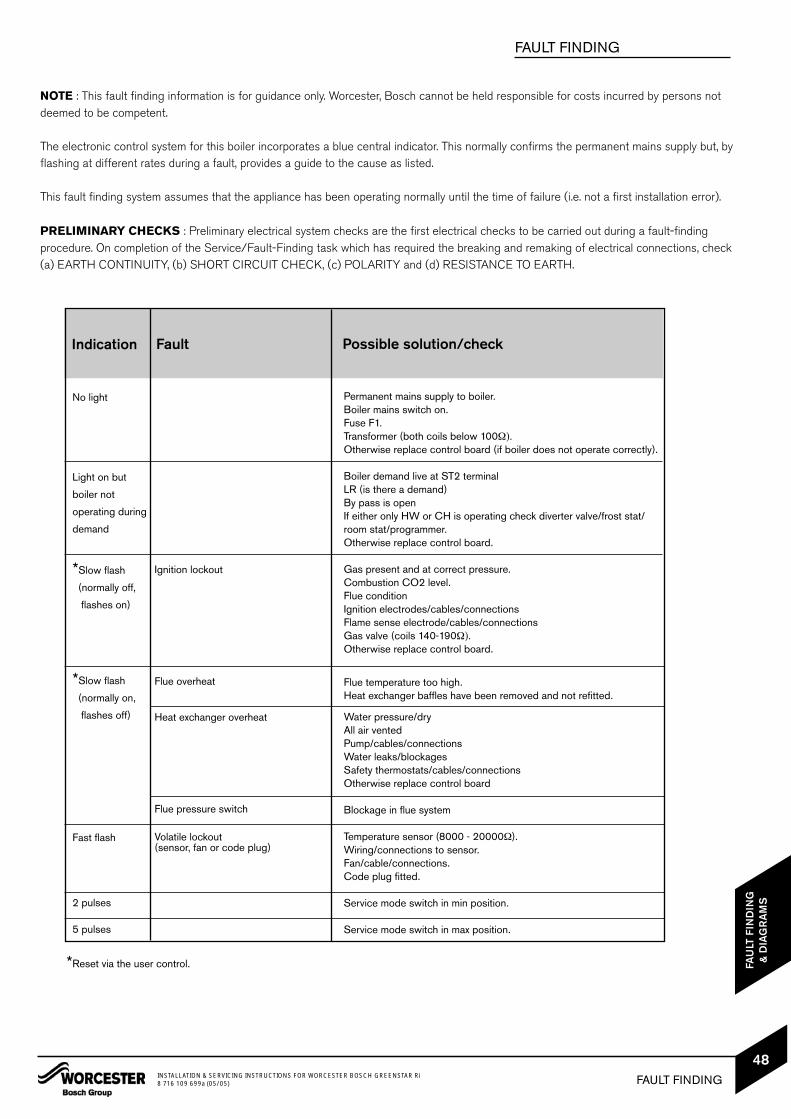
NOTE : This fault finding information is for guidance only. Worcester, Bosch cannot be held responsible for costs incurred by persons notdeemed to be competent.
The electronic control system for this boiler incorporates a blue central indicator. This normally confirms the permanent mains supply but, byflashing at different rates during a fault, provides a guide to the cause as listed.
This fault finding system assumes that the appliance has been operating normally until the time of failure (i.e. not a first installation error).
PRELIMINARY CHECKS : Preliminary electrical system checks are the first electrical checks to be carried out during a fault-findingprocedure. On completion of the Service/Fault-Finding task which has required the breaking and remaking of electrical connections, check (a) EARTH CONTINUITY, (b) SHORT CIRCUIT CHECK, (c) POLARITY and (d) RESISTANCE TO EARTH.
FAULT FINDING
*Reset via the user control.
FAULT FINDINGINSTALLATION & SERVICING INSTRUCTIONS FOR WORCESTER BOSCH GREENSTAR Ri8 716 109 699a (05/05)
48
FAU
LT F
IND
ING
& D
IAG
RA
MS
Indication Fault Possible solution/check

MAIN FUNCTION
NO
YE
SP
ER
MA
NE
NT
MA
IN S
UP
PLY
TO B
OIL
ER
BO
ILE
RD
EM
AN
DFR
OM
SYS
TEM
Fan
tost
art
spee
d.
Pum
p O
N.
Pre
purg
eth
en ig
nitio
nsp
ark
4 s
econ
ds
BLU
ELI
GH
TO
N
BU
RN
ER
LIT?
GR
EE
NFL
AM
ELI
GH
TO
N
Fan
run
10
sec
onds
then
re-
spar
k
5th
atte
mpt
?LO
CK
OU
T
Sta
balis
atio
nth
en f
an lo
w
45
sec
onds
Fan
(& g
as)
mod
ulat
ion
to a
chie
vese
t te
mpe
ratu
re(3
5-8
2°C
)
EN
D O
FB
OIL
ER
DE
MA
ND
Gas
val
veO
FF
Pum
p ru
n 3
min
utes
Fan
run
30
seco
nds
Ove
r te
mpe
ratu
re s
hut-
dow
n if
wat
er te
mpe
ra-
ture
is 5
°C a
bove
set
valu
e.
Fan
over
run
30
sec
onds
3 m
inut
e w
ait
Boi
ler
tem
pera
ture
belo
w 8
°CR
un a
utof
rost
stat
func
tion
PR
OTE
CTI
ON
SYS
TEM
S
Pum
p an
tisei
zeP
ump
run
5 s
econ
dsev
ery
24
hrs
NO
YE
S
MAIN FUNCTION INSTALLATION & SERVICING INSTRUCTIONS FOR WORCESTER BOSCH GREENSTAR Ri8 716 109 699a (05/05)
49
FAU
LT F
IND
ING
& D
IAG
RA
MS

CONTROLS To comply with the Building Regulations, each section must have a tick in one or other of the boxes
TIME & TEMPERATURE CONTROL TO HEATING ROOM T/STAT & PROGRAMMER/TIMER PROGRAMMABLE ROOMSTAT
TIME & TEMPERATURE CONTROL TO HOT WATER CYLINDER T/STAT & PROGRAMMER/TIMER COMBI BOILER
HEATING ZONE VALVES FITTED NOT REQUIRED
HOT WATER ZONE VALVES FITTED NOT REQUIRED
THERMOSTATIC RADIATOR VALVES FITTED
AUTOMATIC BYPASS TO SYSTEM FITTED NOT REQUIRED
FOR ALL BOILERS CONFIRM THE FOLLOWING
THE SYSTEM HAS BEEN FLUSHED IN ACCORDANCE WITH THE BOILER MANUFACTURER’S INSTRUCTIONS?
THE SYSTEM CLEANER USED
THE INHIBITOR USED
FOR THE CENTRAL HEATING MODE, MEASURE & RECORD
GAS RATE ft3/hr
BURNER OPERATING PRESSURE (IF APPLICABLE) mbar
CENTRAL HEATING FLOW TEMPERATURE °C
CENTRAL HEATING RETURN TEMPERATURE °C
FOR COMBINATION BOILERS ONLY
HAS A WATER SCALE REDUCER BEEN FITTED? YES NO
WHAT TYPE OF SCALE REDUCER HAS BEEN FITTED?
FOR THE DOMESTIC HOT WATER MODE, MEASURE & RECORD
GAS RATE ft3/hr
MAXIMUM BURNER OPERATING PRESSURE (IF APPLICABLE) mbar
COLD WATER INLET TEMPERATURE °C
HOT WATER OUTLET TEMPERATURE °C
WATER FLOW RATE lts/min
FOR CONDENSING BOILERS ONLY CONFIRM THE FOLLOWING
THE CONDENSATE DRAIN HAS BEEN INSTALLED IN ACCORDANCE WITH THE MANUFACTURER’S INSTRUCTIONS? YES
FOR ALL INSTALLATIONS CONFIRM THE FOLLOWING
THE HEATING AND HOT WATER SYSTEM COMPLIES WITH CURRENT BUILDING REGULATIONS
THE APPLIANCE AND ASSOCIATED EQUIPMENT HAS BEEN INSTALLED AND COMMISSIONEDIN ACCORDANCE WITH THE MANUFACTURER’S INSTRUCTIONS
IF REQUIRED BY THE MANUFACTURER, HAVE YOU RECORDED A CO/CO2 RATIO READING? N/A YES CO/CO2 RATIO
THE OPERATION OF THE APPLIANCE AND SYSTEM CONTROLS HAVE BEEN DEMONSTRATED TO THE CUSTOMER
THE MANUFACTURER’S LITERATURE HAS BEEN LEFT WITH THE CUSTOMER
m3/hr
m3/hr
COMMISSIONING ENG’S NAME PRINT CORGI ID No.
SIGN DATE
BOILER SERIAL No. NOTIFICATION No.
BENCHMARK No.
GAS BOILER COMMISSIONING CHECKLISTC O L L E C T I V E M A R K
N/A
N/A

SERVICE INTERVAL RECORDIt is recommended that your heating system is serviced regularly
and that you complete the appropriate Service Interval Record Below.
Service Provider. Before completing the appropriate Service Interval Record below, please ensure you have carried out the service
as described in the boiler manufacturer’s instructions. Always use the manufacturer’s specified spare part when replacing all controls
SERVICE 1 DATE
ENGINEER NAME
COMPANY NAME
TEL No.
CORGI ID CARD SERIAL No.
COMMENTS
SIGNATURE
SERVICE 2 DATE
ENGINEER NAME
COMPANY NAME
TEL No.
CORGI ID CARD SERIAL No.
COMMENTS
SIGNATURE
SERVICE 3 DATE
ENGINEER NAME
COMPANY NAME
TEL No.
CORGI ID CARD SERIAL No.
COMMENTS
SIGNATURE
SERVICE 4 DATE
ENGINEER NAME
COMPANY NAME
TEL No.
CORGI ID CARD SERIAL No.
COMMENTS
SIGNATURE
SERVICE 5 DATE
ENGINEER NAME
COMPANY NAME
TEL No.
CORGI ID CARD SERIAL No.
COMMENTS
SIGNATURE
SERVICE 6 DATE
ENGINEER NAME
COMPANY NAME
TEL No.
CORGI ID CARD SERIAL No.
COMMENTS
SIGNATURE
SERVICE 7 DATE
ENGINEER NAME
COMPANY NAME
TEL No.
CORGI ID CARD SERIAL No.
COMMENTS
SIGNATURE
SERVICE 8 DATE
ENGINEER NAME
COMPANY NAME
TEL No.
CORGI ID CARD SERIAL No.
COMMENTS
SIGNATURE
SERVICE 9 DATE
ENGINEER NAME
COMPANY NAME
TEL No.
CORGI ID CARD SERIAL No.
COMMENTS
SIGNATURE
SERVICE 10 DATE
ENGINEER NAME
COMPANY NAME
TEL No.
CORGI ID CARD SERIAL No.
COMMENTS
SIGNATURE

INSTRUCTION MANUALINSTALLATION, COMMISSIONING& SERVICINGEXCELLENCE COMES AS STANDARDWorcester, Bosch Group
Cotswold Way, Warndon, Worcester WR4 9SW.
Tel. 01905 754624 Fax. 01905 754619
Worcester, Bosch Group is a trading name of BBT
Thermotechnology UK Ltd.
www.worcester-bosch.co.uk
8 716 109 699a (05/05)


![CONSOLIDATED CHECKLIST C5 - US EPA · C5C_PART 264 SUBPARTS K-S_2018.DOCX - Revised: 9/4//18 [Printed: 11/20/18] CONSOLIDATED CHECKLIST C5 . Part 3 of 5 parts . Standards for Owners](https://cdn.vdocuments.net/doc/165x107/5f1c5ec7db7bfe0f2d3b0509/consolidated-checklist-c5-us-epa-c5cpart-264-subparts-k-s2018docx-revised.jpg)
![RCRA Revision Checklist 213 | US EPA ARCHIVE DOCUMENTChecklist 213] [Printed: 8/19/08] April 4, 2006- Page 1 of 21 RCRA REVISION CHECKLIST 213 Burden Reduction Initiative 71 FR 16862-16915](https://cdn.vdocuments.net/doc/165x107/60d55d0ad28ca37e1736fa37/rcra-revision-checklist-213-us-epa-archive-document-checklist-213-printed-81908.jpg)