
Cisco Systems, Inc.All contents are Copyright © 1992–2002 Cisco Systems, Inc. All rights reserved. Important Notices and Privacy Statement.
Page 1 of 15
Data Sheet
Cisco 10720 Internet Router
The industry’s first router combining IP, resilient packet ring, and Ethernet technologies optimized forhigh-speed multitenant Internet services.
The high-performance Cisco 10720 Internet Router is a principle building block in the next-generation metro IP
network. The Cisco 10720 Internet Router (Figure 1) enables service providers to offer innovative and differentiated
IP services to their customers at optical speeds. Equipped with Ethernet technology for customer access and the
innovative Dynamic Packet Transport (DPT) technology for metro optical connectivity, the Cisco 10720 allows
service providers to offer IP services closer to the user, enabling them to better control admission to network
resources.
Powered by Cisco IOS® Software and Parallel Express Forwarding (PXF) technology, the Cisco 10720 is a
cost-effective, reliable platform that not only supports the full suite of IP routing protocols such as Intermediate
System-to-Intermediate System (IS-IS), Open Shortest Path First (OSPF) and Border Gateway Protocol (BGP), but
also enables value-added services. Use the Cisco 10720 to efficiently introduce advanced features such as virtual
private networks (VPNs), voice over IP (VoIP), and transparent LAN services (TLS) without compromising on
performance.
With the rapid growth in bandwidth-intensive applications on the Internet, the demand for Internet connectivity has
grown exponentially in the past few years. Service providers are seeking ways to offer Internet access at ever-faster
speeds and to differentiate themselves from competitors by offering value-added services to their customers.
Traditional optical networking products, such as Synchronous Optical Network (SONET) add-drop multiplexers
(ADMs), are only optimized for voice services delivery. To deliver high-speed Internet access, service providers are
required to deploy an overlay IP network, which is complex, bandwidth inefficient, and difficult to manage. The
Cisco 10700 Series can be deployed directly over fiber, enabling service providers to offer IP+Optical access without
the need for a SONET or Synchronous Digital Hierarchy (SDH) optical transport infrastructure, but maintaining
carrier-class SONET/SDH characteristics for management and restoration.
Figure 1
Cisco 10720 Internet Router

Cisco Systems, Inc.All contents are Copyright © 1992–2002 Cisco Systems, Inc. All rights reserved. Important Notices and Privacy Statement.
Page 2 of 15
The Cisco IP+Optical architecture, incorporating Cisco 12000 Series Internet routers in the core and at the provider edge and the Cisco 10720
for metro access (Figure 2), provides a unique solution to service providers. This solution is applicable to both new service providers who are
looking to build networks that deliver data, voice, and video services over IP and traditional service providers who want to optimize and
extend their IP network infrastructures.
Figure 2
Metro IP Architecture
The Cisco 10720 Internet Router is equipped with three types of 24-port or 4 GE+8FE Ethernet access modules and four versions of
optical-reach DPT or POS uplink modules. The uplink module is equipped with two physical OC-48/STM-16 ports. With two rack units,
the Cisco 10720 is suitable for deployment in office buildings and business parks. The flexible Ethernet options support either of these
options. When deployed in multitenant units (MTUs), the Cisco 10720 allows service providers to offer direct Ethernet access using
in-building Category 5 wiring (Figure 3). Alternatively, the Cisco 10720 can aggregate wireless or Long-Reach Ethernet (LRE) implemented
over the existing telephone wiring, using complementary Cisco technologies such as Aironet® wireless devices and Catalyst® switches.
Figure 3
Business-Class Multitenant Ethernet Access
The DPT uplink allows service providers to deploy Cisco 10720 Internet routers in metro architectures directly over fiber. DPT is the
market-leading resilient packet ring (RPR) solution based on the Cisco developed, MAC-layer Spatial Reuse Protocol (SRP). SRP is open and
freely available as IETF Informational RFC 2892. Additionally, Cisco has submitted SRP to the IEEE 802.17 RPR Working Group for
consideration as the industry standard. DPT combines the intelligence of IP routing with the bandwidth efficiencies of optical rings. Designed
primarily for metropolitan area networks (MANs), DPT enables service providers to construct highly reliable, cost-effective optical
infrastructures for scalable Internet service delivery.
Regional Metro IP
Cisco 12000
Cisco10720
Cisco10720
Cisco 12000
Metro IP Access
Metro IP Access
Metro DPT RingOC-48c/STM-16
Cisco10720
Cisco10720

Cisco Systems, Inc.All contents are Copyright © 1992–2002 Cisco Systems, Inc. All rights reserved. Important Notices and Privacy Statement.
Page 3 of 15
Key Benefits
Building Block for Metro Optical Internet
The product’s architecture and on-board DPT optical uplink support allow service providers to offer high-speed IP services at the network
edge. The platform uses Ethernet technology for simple, cost-effective customer access and DPT for metro network connectivity. This allows
service providers to bypass traditional DS1 and DS3 access options. The dual-counter rotating ring technology of DPT is cost effective
because it uses both rings and can be deployed over dark fiber while maintaining the less than 50 ms restoration common in SONET/SDH
systems. For multiservice applications, DPT can also be deployed over traditional SONET/SDH ADMs and wavelength-division multiplexing
(WDM) systems.
Ethernet Customer Connectivity
The various versions of the Ethernet modules available for the Cisco 10720 provide flexible deployment options. The copper (TX) and the
fiber multimode (FX-MM) versions accommodate copper or multimode fiber deployments within MTUs and the FX single mode (SM) allows
for deployment of the Cisco 10720 in a central location covering Ethernet connectivity to buildings located up to 15 km away. Similarly, the
SX and LH versions of pluggable optics for the Gigabit Ethernet ports provide coverage up to 10 km.
High-Performance IP Routing
The Cisco 10720 Internet Router is a fully functional router powered by Cisco IOS Software and the PXF technology. It supports all unicast
and multicast IP routing protocols, advanced buffering and scheduling mechanisms, and the capability to store up to 250,000 routes. It also
supports a forwarding rate of approximately 2 mpps with IP services enabled.
Metro Networking Solutions
The Cisco 10720 Internet Router is designed to ideally support services to the metro with its RPR architecture for optimal fiber connectivity
as well as features such as IP class of service, TLS, VoIP, and VPN services.
Comprehensive IP Class-of-Service Features
The Cisco 10720 Internet Router software is based on industry-leading Cisco IOS Software. IP forwarding as well as the following advanced
IP quality-of-service (QoS) features are performance optimized to ensure highest possible throughput in every port. These features allow
service providers to offer differentiated service (such as gold, silver and bronze) to their customers via the various QoS features that allow
bandwidth control and prioritization of traffic:
• Modular quality-of-service (QoS) command-line interface (CLI) (MQC)—A framework that allows configuration of QoS features:
– Versatile traffic management system (VTMS), the latest scheduling technique for servicing output queues based on traffic classes and
controlling the order and frequency that output queues are serviced based on their configuration
– Committed access rate (CAR) to classify and rate-limit IP flows
– Weighted Random Early Detection (WRED) for Transmission Control Protocol (TCP) congestion avoidance on both the Ethernet and
the OC-48 uplink ports
• Turbo access control lists (ACLs)—Access list processing without affecting performance
Adaptive Network Processing for Future IP Service Enhancements
The Cisco 10720’s central processing engine consists of two sets of PXF network processors—an array of individual, programmable
subprocessors. This architecture not only allows for parallel processing of 32 packets, but it also allows new features to be developed in
microcode and implemented efficiently with a simple software download. Unlike the traditional designs based on application-specific
integrated circuits (ASICs), which require a hardware change for introducing new features, the PXF-based architecture allows for value-added
service features such as IP VPNs and TLS to be developed in short timeframes and implemented in new releases of Cisco IOS Software without
sacrificing performance.

Cisco Systems, Inc.All contents are Copyright © 1992–2002 Cisco Systems, Inc. All rights reserved. Important Notices and Privacy Statement.
Page 4 of 15
Cisco 10720 Internet Router Solutions
Although primarily designed for high-speed Internet services for multitenant and business-park applications in the metro, the Cisco 10720
Internet Router is also suitable for a range of other applications such as: Internet data center applications, intrapoint of presence (POP)
aggregation, and VoIP aggregation.
Figure 4
Multitenant Internet Access
Multitenant Internet Access
Cisco 10720 Internet Routers can be deployed in different buildings within the metro on a DPT ring, providing differentiated services to
various customers within the buildings (Figure 4).
Figure 5
Business Park Internet Access-Option 1
OC-48c/STM-16 DPT2 x 2.5 Gbps
Cisco10720
Cisco10720 Intracity POP
Regional Metro Network
Building 1
Building 2
OC-48c/STM-16 DPT2 X 2.5Gps
Cisco10720
Central Officeor POP
10-15 Km RadiusFX SM Ethernet

Cisco Systems, Inc.All contents are Copyright © 1992–2002 Cisco Systems, Inc. All rights reserved. Important Notices and Privacy Statement.
Page 5 of 15
Business Park Internet Access
The single-mode FX Ethernet option allows deployment of the Cisco 10720 Internet Router in a central building within a business park and
the ability to serve up to 24 different buildings within a 15-km radius (Figure 5).
A second business park deployment application shows the Cisco 10720 coupled with the Cisco ONS 15194 to star wire campus buildings.
The Cisco 10720 Internet Router is used to connect each building to the DPT ring, as shown in Figure 6.
Figure 6
Business Park Internet Access-Option 2
Internet Data Center Figure 7 illustrates redundant load sharing using the Cisco 10720 Internet Router in Web farms.
Figure 7
Internet Data Center
Regional DPT Ring
Cisco10720
Cisco10720
Cisco12000
Central Building
Cisco ONS 15194
OC-48/STM-16Metro Ring
Web Hosting CenterWeb Hosting Center
Cisco 10720Cisco 10720

Cisco Systems, Inc.All contents are Copyright © 1992–2002 Cisco Systems, Inc. All rights reserved. Important Notices and Privacy Statement.
Page 6 of 15
IntraPOP Aggregation The Cisco 10720 can also be deployed within a POP to aggregate access devices as shown in Figure 8.
Figure 8
IntraPOP Aggregation
The support for POS functionality on the OC-48 ports (Figure 9) allows service providers to offer IP Transit/Co-location services.
Figure 9
IP Transit./Co-location Services
DPT OC-48c/STM-16
Cisco 10720Cisco 10720
Backbone
POP
Exchange Point
SP1 SP2 SP3 SP4
Cisco 10720
POP1 POP2
Cisco 12000Cisco 12000
GEGEGEGE
OC-48 POS Link to POP1 OC-48 POS Link to POP2
Cisco Systems, Inc.All contents are Copyright © 1992–2002 Cisco Systems, Inc. All rights reserved. Important Notices and Privacy Statement.
Page 7 of 15
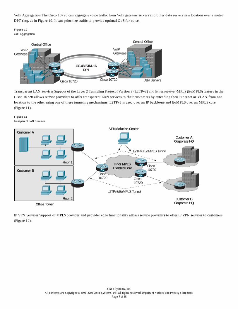
VoIP Aggregation The Cisco 10720 can aggregate voice traffic from VoIP gateway servers and other data servers in a location over a metro
DPT ring, as in Figure 10. It can prioritize traffic to provide optimal QoS for voice.
Figure 10
VoIP Aggregation
Transparent LAN Services Support of the Layer 2 Tunneling Protocol Version 3 (L2TPv3) and Ethernet-over-MPLS (EoMPLS) feature in the
Cisco 10720 allows service providers to offer transparent LAN services to their customers by extending their Ethernet or VLAN from one
location to the other using one of these tunneling mechanisms. L2TPv3 is used over an IP backbone and EoMPLS over an MPLS core
(Figure 11).
Figure 11
Transparent LAN Services
IP VPN Services Support of MPLS provider and provider edge functionality allows service providers to offer IP VPN services to customers
(Figure 12).
OC-48/STM-16DPT
Central OfficeCentral Office
Cisco 10720Cisco 10720 Data Servers
VoIPGateways
VoIPGateways
IP or MPLSEnabled Core
Customer ACustomer A
Corporate HQ
VPN Solution Center
Customer BCorporate HQ
Customer B
Office Tower
Floor 1
Floor 2
Cisco10720
Cisco10720
Cisco10720
L2TPv3/EoMPLS Tunnel
L2TPv3/EoMPLS Tunnel

Cisco Systems, Inc.All contents are Copyright © 1992–2002 Cisco Systems, Inc. All rights reserved. Important Notices and Privacy Statement.
Page 8 of 15
Figure 12
IP VPN over MPLS Backbone
Features at a Glance
Hardware Features
Central Processing Engine
The central processing engine consists of two sets of processors that manage the control plane and data plane traffic. The PXF network
processors manage the data plane and support IP forwarding as well as advanced QoS features. The multiple processors in the PXF process
packets simultaneously at the rate of approximately 2 mpps (Figure 13).
Figure 13
PXF Processing
Redundant Power Supply
The Cisco 10720 Internet Router is equipped with a dual power supply by default. Both AC and DC power supplies are supported as options.
Interface Modules
The Cisco 10720 Internet Router has two dedicated slots for interface modules (modules are not interchangeable or hot swappable):
MPLSEnabled Core
Customer A
Customer A’sCorporate Intranet
VPN Solution Center
Customer B’sCorporate Intranet
Customer B
Office Tower 1
Office Tower 2
Cisco10720
Cisco10720
Cisco10720
CE
CECE
CEProvider Provider Edge
Provider Edge
ProviderEdge
Provider
Input Buffer
Output Buffer
CPU#0
CPU#1
CPU#2
CPU#3
CPU#4
CPU#5
CPU#6
CPU#7
CPU#8
CPU#9
CPU#10
CPU#11
CPU#12
CPU#13
CPU#14
CPU#15
Memory Memory Memory Memory
Feature 1Feature 2
Feature 3Feature 4
Input Buffer
Output Buffer
CPU#0
CPU#1
CPU#2
CPU#3
CPU#4
CPU#5
CPU#6
CPU#7
CPU#8
CPU#9
CPU#10
CPU#11
CPU#12
CPU#13
CPU#14
CPU#15
Memory Memory Memory Memory
Feature 5Feature 6
Feature 7Feature 8
Simultaneous processing of 4 packets

Cisco Systems, Inc.All contents are Copyright © 1992–2002 Cisco Systems, Inc. All rights reserved. Important Notices and Privacy Statement.
Page 9 of 15
• Upper slot is dedicated for a console/auxiliary module or a DPT or POS (Packet Over SONET) uplink module equipped with two physical
ports of OC-48c/STM-16c.
– DPT/POS uplink module—This module provides an aggregate bandwidth of approximately 5 Gbps. The cards are available in four
versions of optics—Short Reach (SR), Intermediate Reach (IR), Long Reach 1 (LR1) (40 km) and Long Reach 2 (LR-2) (80 km) with
two small form-factor OC-48 ports with LC connectors (Figure 14). All uplink modules also have one console port and one auxiliary
port for management purposes, both with RJ-45 connectors.
– Console/auxiliary module—This module has only the console and auxiliary ports and no OC-48c/STM-16c ports. (Figure 15).
Figure 14
OC-48c/STM16c SR, IR, LR1, or LR2
Figure 15
Console/Auxiliary Module
• Lower slot is dedicated for either a 24-port Fast Ethernet module or a combined 4-port Gigabit Ethernet and 8-port Fast Ethernet module
– 24-port Fast Ethernet module—This module is available in TX (100-m reach) as in Figure 15, FX-MM (2-km reach) or FX-SM (15-km
reach) as in Figure 16 and 17. The TX module is equipped with RJ-45 connectors while the FX-SM and FX-MM modules are equipped
with MT-RJ connectors.
– 4-Port Gigabit Ethernet + 8-port Fast Ethernet module—The Gigabit Ethernet ports are equipped with small-form-factor pluggable
(SFP) optics that are available in SX (2-km reach) or LH (10-km reach) optics (Figure 18).
Figure 16
24-Port 10/100 TX
Figure 17
24-Port 100-Mbps FX-SM or FX-MM
Figure 18
4-Port Gigabit Ethernet + 8-Port 10/100 TX

Cisco Systems, Inc.All contents are Copyright © 1992–2002 Cisco Systems, Inc. All rights reserved. Important Notices and Privacy Statement.
Page 10 of 15
Software Features
• SRP features—IPS with less than 50-ms restoration time and SRP Management Information Base (MIB) support
• IP routing protocols including IS—IS, OSPF, and BGP
• Multicast support including protocol-independent multicase (PIM) sparse mode (SM), PIM dense mode (DM), Multiprotocol BGP
• L2VPN—L2TPv3 or EoMPLS for Ethernet based Layer 2 VPN services
• L3VPN—MPLS provider and provider edge functionality
• QoS features—Modular QoS CLI, CAR, WRED, versatile traffic-management system (VTMS) traffic shaping, and access lists
• Ethernet features—10/100 speed autonegotiation, HDX-FDX negotiation and time domain reflectometry (TDR) for 10/100BaseTX, Hot
Standby Routing Protocol (HSRP)/Multiple HSRP
• Security including authentication, authorization, and accounting (AAA); RADIUS authentication; TACACS+, encrypted passwords; and
so on
Management and Administration
• Cisco IOS CLI
• TACACS+ and RADIUS
• Configuration and administration features including Telnet and Cisco Discovery Protocol
• Serial (auxiliary) and console ports for local and remote administration
• Remote software download via Trivial File Transfer Protocol (TFTP) and Remote Copy Protocol (RCP)
• IP over data communication channel (DCC) for remote management of the Cisco ONS 15104 OC-48/STM-16 Optical Regenerator,
where applicable
• 64-MB built-in Flash memory for software and configuration load
• Optical receive power monitoring support on OC-48/STM-16 and GE interface
• Supported MIBs include Simple Network Management Protocol (SNMP), SRP, SONET, Etherlike, and OSPF
• Autoinstall feature support for remote deployments
Specifications
Physical
• Weight: 34 lb (15.3 kg)
• Dimensions (H x W x D): 3.5 x 17.25 x 18.25 in. (8.9 x 43.81 x 46.35 cm)
• Mounting options: 19 in., 23 in., 24 in. EIA; ETSI; front-, mid-, or rear-rack mounting; wall mounting; table mounting
Upper Slot Modules
• Two-port single-mode OC-48c/STM-16c SRP or POS:
– SR 2 km (1.2 miles)
– IR 15 km (9.3 miles)
– LR1 40 km (25 miles)
– LR2 80 km (50 miles)
– Weight: 3.0 lb (1.35kg)
– Dimensions (H x W x D): 0.96 x 13.16 x 8.55 in. (2.44 x 33.43 x 21.71 cm)
– LEDs: Overtemp, cardfail, system status, power, active, carrier, receive packet, SRP wrap, and SRP passthrough
• Console/Auxiliary Module
– Console and Auxiliary ports
– Weight 2.4 lbs (1.09 kg)
– Dimensions (H x W x D): 0.96 x 13.16 x 8.55 in. (2.44 x 33.43 x 21.71 cm)
– LEDs: Overtemp, cardfail, system status, and power

Cisco Systems, Inc.All contents are Copyright © 1992–2002 Cisco Systems, Inc. All rights reserved. Important Notices and Privacy Statement.
Page 11 of 15
Lower slot module
• 24-port 10/100Base-TX access module:
– Weight: 2.8 lb (1.26 kg)
– Dimensions (H x W x D): 1.49 x 13.16 x 8.55 in. (3.78 x 33.42 x 21.71 cm)
– LEDs: Cardfail, power, error (R), link/active (G), and 100 Mbps
– Connectors: RJ-45
• 24-port 100Base-FX access module (FX-SM or FX-MM):
– Weight: 3.2 lb (1.44 kg)
– Dimensions (H x W x D): 1.49 x 13.16 x 8.55 in. (3.78 x 33.42 x 21.71 cm)
– LEDs: error (R), link (G), active, cardfail, power
• 4-Port 1000Base-FX + 8-port 10/100Base-TX access module:
– Weight: 2.8 lb (1.26 kg)
– Dimensions (H x W x D): 1.49 x 13.16 x 8.55 in. (3.78 x 33.42 x 21.71 cm)
– LEDs: Cadfail, power, error (R), link/active (G), and 100Mbps
Environmental
• Temperature:
– Operating: 32 to 104 F (0 to 40 C)
– Nonoperating: -4 to 149 F (-20 to 65 C)
• Relative humidity:
– Operating: 10 to 85 percent noncondensing
– Nonoperating: 5 to 95 percent noncondensing
• Altitude:
– Operating: 0 to 10,000 ft (0 to 3000 m)
– Nonoperating: 0 to 15,000 ft (0 to 4570 m)
• Heat dissipation:
– Max DC: 500W o Max AC: 500W
• Shock:
– Operating (half sine): 21 in. per sec (0.53 m per sec)
– Nonoperating (trapezoidal pulse): 20 G1, 52 in. per sec (1.32 m per sec)
• Acoustic noise: Max 60dBa
• Vibration:
– Operating: 0.35 Grms2 from 3 to 500 Hz
– Nonoperating: 1.0 Grms from 3 to 500 Hz
Safety Compliance
• ACA TS 001
• AS/NZS 3260
• EN/IEC 60825 Laser Safety
• CSA C22.2 No. 950 ~ UL 1950
• IEC60950 second edition with A1-A4
• EN60950 second edition with A1-A4
1. G is a value of acceleration, where 1 G equals 32.17 ft/sec (9.81 m/sec)
2. Grms is the root mean square value of acceleration

Cisco Systems, Inc.All contents are Copyright © 1992–2002 Cisco Systems, Inc. All rights reserved. Important Notices and Privacy Statement.
Page 12 of 15
Immunity Compliance
• EN 300 386/EN 300 386-2
• EN55024
• EN50082-1
Electromagnetic Emissions Certification
• AS/NZS 3548 - Class A
• FCC Part 15 (47CFR15 Subpart B) - Class A
• EN 300 386/EN 300 386-2 - class A/B3
• EN55022 class A/B3
• EN61000-3-2
• EN61000-3-3
• ICES-003 - Class A
• VCCI - Class A
• CISPR 22 -Class A/B3
• BSMI (Taiwan) - Class A4
Immunity Tests
• EN/IEC-61000-4-2: ESD
• EN/IEC-61000-4-3: Radiated immunity
– EN/IEC-61000-4-4: EFT
– EN/IEC 61000-4-5: Surge
– EN/IEC-61000-4-6: Conducted immunity
– EN/IEC-61000-4-11: Voltage dips and sags
Network Equipment Building Systems (NEBS3)
Designed to meet Telcordia (Bellcore) NEBS:
• GR-1089-CORE
• GR-63-CORE
Power
Dual DC power supply:
• Total DC input power: 200 to 300W (measured max)
• Heat dissipation: 500W
• Input voltage: -48/-60VDC nominal
• Maximum input current: 9.0A
• Typical input current: 3.0 to 4.0A
Dual AC power supply:
• Total AC input power: 200 to 300W (measured max)
• Heat dissipation: 500W
• Input voltage: 100 to 240VAC
3. Class B with shielded Ethernet cable (CAT5); Class A with unshielded Ethernet cable (CAT5)
4. Requires the use of shielded (CAT 5) Ethernet cable on the Fast Ethernet TX ports for 10720-FE-TX and 10720-GE-FE-TX; not applicable for 10720-GE-FE-TX-B
Cisco Systems, Inc.All contents are Copyright © 1992–2002 Cisco Systems, Inc. All rights reserved. Important Notices and Privacy Statement.
Page 13 of 15
• Input line frequency: 50/60 Hz
• Input current: 2.5 to 5.0A
Software
Cisco IOS Software Release 12.0(19)SP or 12.0(21)ST or later
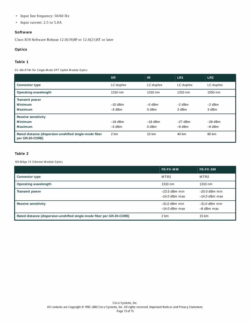
Optics
Table 1
Table 2
OC-48c/STM-16c Single-Mode DPT Uplink Module Optics
SR IR LR1 LR2
Connector type LC duplex LC duplex LC duplex LC duplex
Operating wavelength 1310 nm 1310 nm 1310 nm 1550 nm
Transmit power
Minimum
Maximum
–10 dBm
–3 dBm
–5 dBm
0 dBm
–2 dBm
3 dBm
–2 dBm
3 dBm
Receive sensitivity
Minimum
Maximum
–18 dBm
–3 dBm
–18 dBm
0 dBm
–27 dBm
–9 dBm
–28 dBm
–9 dBm
Rated distance (dispersion-unshifted single-mode fiberper GR-20-CORE)
2 km 15 km 40 km 80 km
100-Mbps FX Ethernet Module Optics
FE-FX-MM FE-FX-SM
Connector type MT-RJ MT-RJ
Operating wavelength 1310 nm 1310 nm
Transmit power –23.5 dBm min
–14.0 dBm max
–20.0 dBm min
–14.0 dBm max
Receive sensitivity –31.0 dBm min
–14.0 dBm max
–31.0 dBm min
–8 dBm max
Rated distance (dispersion-unshifted single-mode fiber per GR-20-CORE) 2 km 15 km

Cisco Systems, Inc.All contents are Copyright © 1992–2002 Cisco Systems, Inc. All rights reserved. Important Notices and Privacy Statement.
Page 14 of 15
Table 3
Table 4
For additional information, please go to: http://www.cisco.com/go/metroip.
1000Mpbs Gigabit Ethernet SFP optics
Feature SFP-SX SFP-LH/LX SFP-ZX
Connector type LC duplex LC duplex LC Duplex
Operating wavelength -TX 850nm VCSEL 1310nm Fabry-Perot Laser 1550 nm
Transmit power
Minimum
Maximum
–9.5 dBm
–4 dBm
–9.5 dBm
–3 dBm
0 dBm
5 dBm
Receiver sensitivity
Minimum
Maximum
–18 dBm
–4 dBm
–19 dBm
–3 dBm
-23 dBm
-3 dBm
Rated distance (50/125um MMF) 500 to 550m — —
Rated distance (62.5/125um MMF) 220 to 275m — —
Rated distance (9/125um SMF) — 10 km 70 km
Ordering Information
Part number Description
CISCO10720-AC-A Cisco 10720 Internet Router with dual AC power supply—Rev A
CISCO10720-DC-A Cisco 10720 Internet Router with dual DC power supply—Rev A
10720-FE-TX 24-port 10/100 Ethernet Access Module—RJ-45 connectors
10720-FE-FX-MM 24-port 100-Mbps Multimode Fiber Ethernet Access Module 2 km—MTRJ connectors
10720-GE-FE-TX 4-Port GE 8-Port 10/100 Ethernet RJ45
10720-GE-FE-TX -B 4-Port GE 8-Port 10/100 Ethernet RJ45-Revision B
10720-GE-SFP-SX GE SFP—Short Reach 550M LC connectors
10720-GE-SFP-LH GE SFP—Intermediate Reach 10KM LC connectors
GLC-ZX-SM GE SFP—Long Reach 70KM LC connectors
10720-SR-LC OC-48c/STM-16c SRP Short Reach (2 km) Uplink Module—LC connectors
10720-IR-LC OC-48c/STM-16c SRP Intermediate Reach (15 km) Uplink Module—LC connectors
10720-LR1-LC OC-48c/STM-16c SRP Long Reach (40 km) Uplink Module—LC connectors
10720-LR2-LC OC-48c/STM-16c SRP Long Reach (80 km) Uplink Module—LC connectors
10720-SR-LC-POS OC-48c/STM-16c POS Short Reach (2 km) Uplink Module—LC connectors
10720-IR-LC-POS OC-48c/STM-16c POS Intermediate Reach (15 km) Uplink Module—LC connectors
10720-LR1-LC-POS OC-48c/STM-16c POS Long Reach (40 km) Uplink Module—LC connectors
10720-LR2-LC-POS OC-48c/STM-16c POS Long Reach (80 km) Uplink Module—LC connectors
10720-CON-AUX Console/Auxiliary Module

Corporate HeadquartersCisco Systems, Inc.170 West Tasman DriveSan Jose, CA 95134-1706USAwww.cisco.comTel: 408 526-4000
800 553-NETS (6387)Fax: 408 526-4100
European HeadquartersCisco Systems International BVHaarlerbergparkHaarlerbergweg 13-191101 CH AmsterdamThe Netherlandswww-europe.cisco.comTel: 31 0 20 357 1000Fax: 31 0 20 357 1100
Americas HeadquartersCisco Systems, Inc.170 West Tasman DriveSan Jose, CA 95134-1706USAwww.cisco.comTel: 408 526-7660Fax: 408 527-0883
Asia Pacific HeadquartersCisco Systems, Inc.Capital Tower168 Robinson Road#22-01 to #29-01Singapore 068912www.cisco.comTel: +65 6317 7777Fax: +65 6317 7799
Cisco Systems has more than 200 offices in the following countries and regions. Addresses, phone numbers, and fax numbers are listed on the
C i s c o W e b s i t e a t w w w . c i s c o . c o m / g o / o f f i c e s
Argentina • Australia • Austria • Belgium • Brazil • Bulgaria • Canada • Chile • China PRC • Colombia • Costa Rica • Croatia
Czech Republic • Denmark • Dubai, UAE • Finland • France • Germany • Greece • Hong Kong SAR • Hungary • India • Indonesia • Ireland
Israel • Italy • Japan • Korea • Luxembourg • Malaysia • Mexico • The Netherlands • New Zealand • Norway • Peru • Philippines • Poland
Portugal • Puerto Rico • Romania • Russia • Saudi Arabia • Scotland • Singapore • Slovakia • Slovenia • South Africa • Spain • Sweden
Switzer land • Taiwan • Thai land • Turkey • Ukraine • United Kingdom • United States • Venezuela • Vietnam • Zimbabwe
All contents are Copyright © 1992–2003 Cisco Systems, Inc. All rights reserved. Aironet, Catalyst, Cisco, Cisco Systems, the Cisco Systems logo, and Cisco IOS are registered trademarks or trademarks of Cisco Systems, Inc.
and/or its affiliates in the U.S. and certain other countries.
All other trademarks mentioned in this document or Web site are the property of their respective owners. The use of the word partner does not imply a partnership relationship between Cisco and any other company.
(0303R) 203082.B/ETMG_05/03


