Engineering Conferences InternationalECI Digital ArchivesCO2 Summit III: Pathways to Carbon Capture,Utilization, and Storage Deployment Proceedings
5-25-2017
CO2 Capture from Industrial Sources by High-temperature SorbentsMatteo C. RomanoPolitecnico di Milano, Italy, [email protected]
Giampaolo ManzoliniPolitecnico di Milano, Italy
Stefano ConsonniPolitecnico di Milano, Italy
Follow this and additional works at: http://dc.engconfintl.org/co2_summit3
Part of the Engineering Commons
This Abstract and Presentation is brought to you for free and open access by the Proceedings at ECI Digital Archives. It has been accepted for inclusionin CO2 Summit III: Pathways to Carbon Capture, Utilization, and Storage Deployment by an authorized administrator of ECI Digital Archives. Formore information, please contact [email protected].
Recommended CitationMatteo C. Romano, Giampaolo Manzolini, and Stefano Consonni, "CO2 Capture from Industrial Sources by High-temperatureSorbents" in "CO2 Summit III: Pathways to Carbon Capture, Utilization, and Storage Deployment", Jen Wilcox (Colorado School ofMines, USA) Holly Krutka (Tri-State Generation and Transmission Association, USA) Simona Liguori (Colorado School of Mines,USA) Niall Mac Dowell (Imperial College, United Kingdom) Eds, ECI Symposium Series, (2017). http://dc.engconfintl.org/co2_summit3/25
CO2 capture from industrial sources by high temperature sorbents
Matteo C. Romano, Giampaolo Manzolini, Stefano Consonni Politecnico di Milano, Department of Energy Group of Energy Conversion Systems (GECoS)
ECI CO2 summit III: CO2 capture, utilization and storage Grand hotel San Michele, Calabria, Italy 22-26 May 2017

SUMMARY
• High temperature sorbent systems for post-
combustion capture • Integration in power plants • Integration in cement plants
• High temperature sorbent systems for pre-combustion capture
• Sorption enhanced reforming for power generation and hydrogen production
• Sorption enhanced WGS in power plants and integrated steel mills
• Sorption enhanced gasification for biofuels production
• Conclusions
2
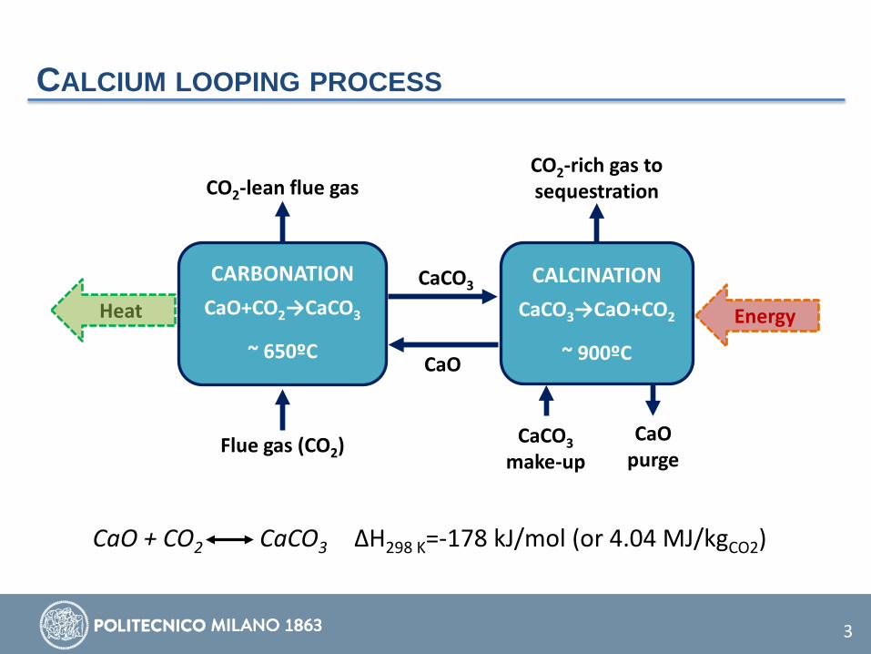
CALCIUM LOOPING PROCESS
CARBONATION
CaO+CO2→CaCO3
~ 650ºC
Energy
Flue gas (CO2)
CO2-lean flue gas
CaCO3
CaO
CO2-rich gas to sequestration
CaCO3 make-up
CaO purge
CALCINATION
CaCO3→CaO+CO2
~ 900ºC
Heat
CaO + CO2 CaCO3 ΔH298 K=-178 kJ/mol (or 4.04 MJ/kgCO2)
3

CALCIUM LOOPING PROCESS
4
• Fast carbonation kinetics at around 650ºC CaO+CO2 CaCO3 • Regeneration in concentrated CO2 atmosphere at >900ºC CaCO3 CaO+CO2
0.0001
0.001
0.01
0.1
1
10
100
600 700 800 900 1000 1100 1200
CO2
parti
al p
ress
ure
(atm
)
Temperature (ºC)
Carbonation
Calcination
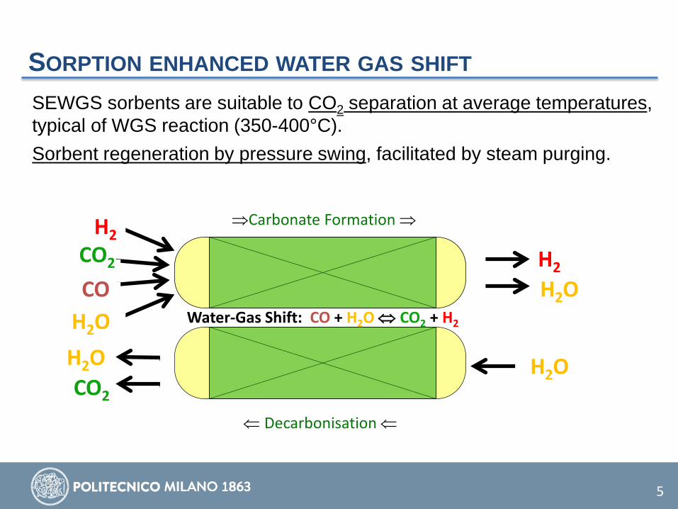
SEWGS sorbents are suitable to CO2 separation at average temperatures, typical of WGS reaction (350-400°C). Sorbent regeneration by pressure swing, facilitated by steam purging.
SORPTION ENHANCED WATER GAS SHIFT
5
H2 H2O
H2O CO
H2 CO2
H2O H2O CO2
Water-Gas Shift: CO + H2O ⇔ CO2 + H2
⇒Carbonate Formation ⇒
⇐ Decarbonisation ⇐
SUMMARY
• High temperature sorbent systems for post-combustion capture • Integration in power plants • Integration in cement plants
• High temperature sorbent systems for pre-combustion capture
• Sorption enhanced reforming for power generation and hydrogen production
• Sorption enhanced WGS in power plants and integrated steel mills
• Sorption enhanced gasification for biofuels production
• Conclusions
6

CAL FOR COAL POWER PLANTS STATE OF THE ART – TRL 6-7 • The technology has been demonstrated at 0.1-2 MW-scale in different lab-scale
and pilot facilities and is technically ready for scale-up. La Pereda (Spain) Darmstad
(Germany) IFK (Germany) La Robla (Spain)
Thermal input 1.7 MWth referred to carbonator
1 MWth referred to calciner
50-230 kWth referred to carbonator 300 kWth referred to the biomass fed to carbonator
Configuration Calciner: CFB Carbonator: CFB
Calciner: CFB Carbonator: CFB
Calciner: CFB Carbonator: FFB* and TFB*
Calciner: CFB Carbonator: CFB
Height Calciner: 15 m Carbonator: 15 m
Calciner: 11.4 m Carbonator: 8.6 m
Calciner: 10 m Carbonator: 10 m (FFB*), 6 m (TFB*)
Calciner: 12 m Carbonator: 12 m
Diameter Calciner: 0.75 m Carbonator: 0.65 m
Calciner: 0.4 m Carbonator: 0.59 m
Calciner: 0.21 m Carbonator: 0.21 m (FFB+), 0.33 m (TFB+)
Calciner: 0.4 m Carbonator: 0.4 m
Flue gas source Integrated with power plant
Flue gas from coal burner
Synthetic flue gas Flue gas generated in carbonator
Calciner operation
Oxy-fired with coal Oxy-fired with coal/propane
Oxy-fired with coal and flue gas recycle
Air-fired with biomass
Project name or website
http://recal-project.eu/ ; http://cao2.eu
http://www.project-scarlet.eu/
http://cal-mod.eu-projects.de/ MenosCO2
Abanades et al., 2015. Emerging CO2 capture systems. Int J Greenh Gas Con, 40, 126-166.
7
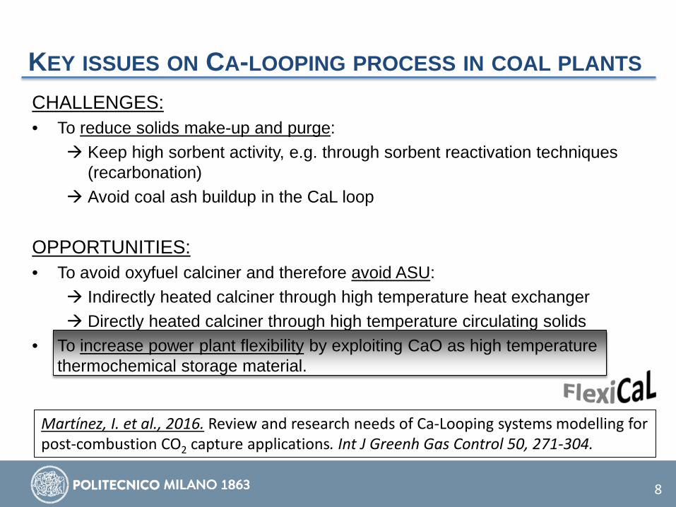
KEY ISSUES ON CA-LOOPING PROCESS IN COAL PLANTS CHALLENGES: • To reduce solids make-up and purge:
Keep high sorbent activity, e.g. through sorbent reactivation techniques (recarbonation)
Avoid coal ash buildup in the CaL loop
OPPORTUNITIES: • To avoid oxyfuel calciner and therefore avoid ASU:
Indirectly heated calciner through high temperature heat exchanger Directly heated calciner through high temperature circulating solids
• To increase power plant flexibility by exploiting CaO as high temperature thermochemical storage material.
8
Martínez, I. et al., 2016. Review and research needs of Ca-Looping systems modelling for post-combustion CO2 capture applications. Int J Greenh Gas Control 50, 271-304.
SUMMARY
• High temperature sorbent systems for post-combustion capture • Integration in power plants • Integration in cement plants
• High temperature sorbent systems for pre-combustion capture
• Sorption enhanced reforming for power generation and hydrogen production
• Sorption enhanced WGS in power plants and integrated steel mills
• Sorption enhanced gasification for biofuels production
• Conclusions
9

CA-LOOPING FOR CEMENT PLANTS Key information on cement plants: • 60% of CO2 emissions derive from CaCO3 calcination and cannot be reduced by
fuel switch, fuel decarbonization or energy efficiency • Modern cement plants are thermally very efficient: waste heat is not enough to
capture high amounts of CO2 by conventional post-combustion amines
CCS
2.5
2.0
1.5
Glob
al C
O2 e
miss
ions
of t
he
cem
ent i
ndus
try
in G
t/a
0.0
2010 2030 2050
44 %
56 %
Source: IEA Cement Roadmap
Increase of energy efficiency Alternative fuels use Reduction of clinker share
Reduction by:
10
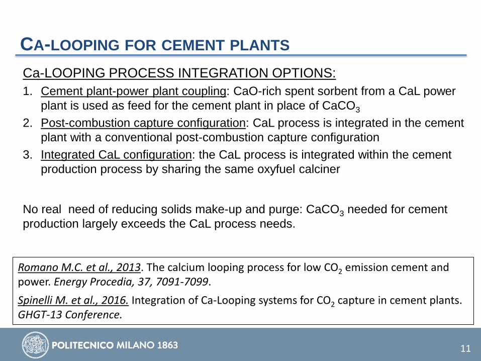
CA-LOOPING FOR CEMENT PLANTS Ca-LOOPING PROCESS INTEGRATION OPTIONS: 1. Cement plant-power plant coupling: CaO-rich spent sorbent from a CaL power
plant is used as feed for the cement plant in place of CaCO3
2. Post-combustion capture configuration: CaL process is integrated in the cement plant with a conventional post-combustion capture configuration
3. Integrated CaL configuration: the CaL process is integrated within the cement production process by sharing the same oxyfuel calciner
11
Romano M.C. et al., 2013. The calcium looping process for low CO2 emission cement and power. Energy Procedia, 37, 7091-7099. Spinelli M. et al., 2016. Integration of Ca-Looping systems for CO2 capture in cement plants. GHGT-13 Conference.
No real need of reducing solids make-up and purge: CaCO3 needed for cement production largely exceeds the CaL process needs.
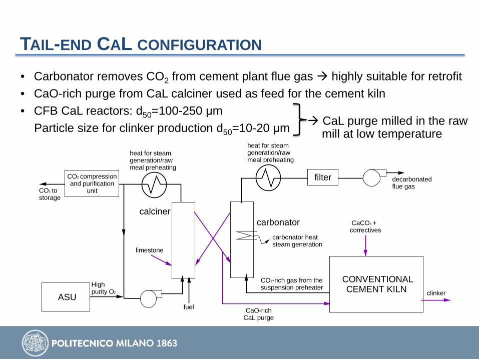
TAIL-END CAL CONFIGURATION
carbonatorcalciner
CaCO3 + correctives
decarbonated flue gasCO2 to
storage
heat for steam generation/raw meal preheating
heat for steam generation/raw meal preheating
High purity O2
fuel
filter
carbonator heat steam generation
CONVENTIONAL CEMENT KILN clinker
CO2-rich gas from the suspension preheater
limestone
CaO-rich CaL purge
ASU
CO2 compression and purification
unit
• Carbonator removes CO2 from cement plant flue gas highly suitable for retrofit • CaO-rich purge from CaL calciner used as feed for the cement kiln • CFB CaL reactors: d50=100-250 μm
Particle size for clinker production d50=10-20 μm CaL purge milled in the raw mill at low temperature

INTEGRATED CAL CONFIGURATION
carbonator
calciner
CO2-rich gas from the kiln
hot clinker
fuel
decarbonated flue gas
heat recovery for steam generation
High purity O2
fuel
filter
clinker coolercooled clinker
cooling air
cooler exhaust airsecondary
airrotary kiln
carbonator heat steam generation
Raw meal preheater 1
Raw meal 1
Raw meal 2
Raw meal preheater 2heat recovery for
steam generation
CaCO3-rich material
precalcined raw meal
ASU
CO2 to storage
CO2 compression and purification
unit
• CaL carbonator highly integrated within the preheating tower, on rotary kiln gas • CaL calciner coincides with the cement kiln pre-calciner • Calcined raw meal as CO2 sorbent in the carbonator • Sorbent has small particle size (d50=10-20 μm) entrained flow reactors

CA-LOOPING FOR CEMENT PLANTS Ca-LOOPING PROCESS INTEGRATION OPTIONS: 1. Cement plant-power plant coupling:
• Excellent expected performance • Easily retrofittable with low cost • Logistic problem: a very large power plant has to be built next to the cement plant
2. Post-combustion capture configuration: • Low uncertainty in the feasibility of the process (very similar to application in
power plants) • Very high CO2 capture expected • Two calciners are present in the system, leading to high fuel consumptions
3. Integrated CaL configuration: • High CO2 capture efficiency without modifying rotary kiln operation (no need of
kiln oxyfiring). • Higher thermal efficiency and lower fuel consumptions expected (compared to
option 2) • New carbonator design and fluid-dynamic regime: fluid-dynamics, heat
management and sorbent performance need verification
14
SUMMARY
• High temperature sorbent systems for post-combustion capture • Integration in power plants • Integration in cement plants
• High temperature sorbent systems for pre-combustion capture
• Sorption enhanced reforming for power generation and hydrogen production
• Sorption enhanced WGS in power plants and integrated steel mills
• Sorption enhanced gasification for biofuels production
• Conclusions
15

HT CAO-BASED SORBENTS FOR NATURAL GAS Process integration strategies based on sorption-enhanced reforming are preferable with natural gas.
CARBONATION Energy
CaCO3
CaO
CALCINATION HT Heat Endoth. Reaction
(SMR)
Chemical energy
HIGH TEMPERATURE HEAT FROM CARBONATION EFFICIENTLY CONVERTED INTO CHEMICAL ENERGY BY STEAM METHANE REFORMING
16
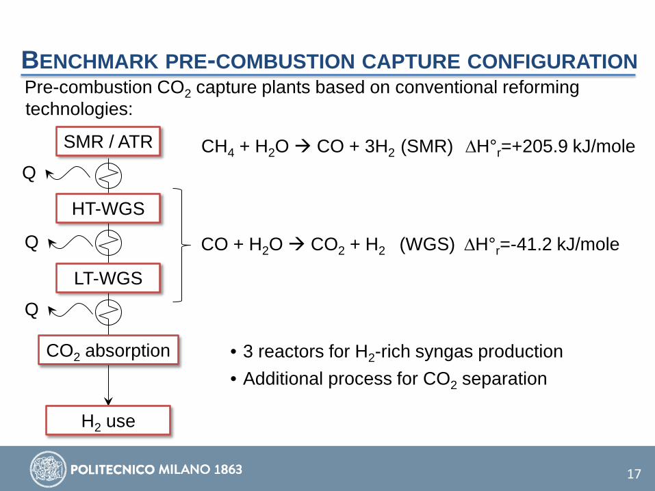
BENCHMARK PRE-COMBUSTION CAPTURE CONFIGURATION Pre-combustion CO2 capture plants based on conventional reforming technologies:
SMR / ATR
HT-WGS
LT-WGS
CO2 absorption
H2 use
CH4 + H2O CO + 3H2 (SMR) ∆H°r=+205.9 kJ/mole
CO + H2O CO2 + H2 (WGS) ∆H°r=-41.2 kJ/mole
• 3 reactors for H2-rich syngas production • Additional process for CO2 separation
Q
Q
Q
17
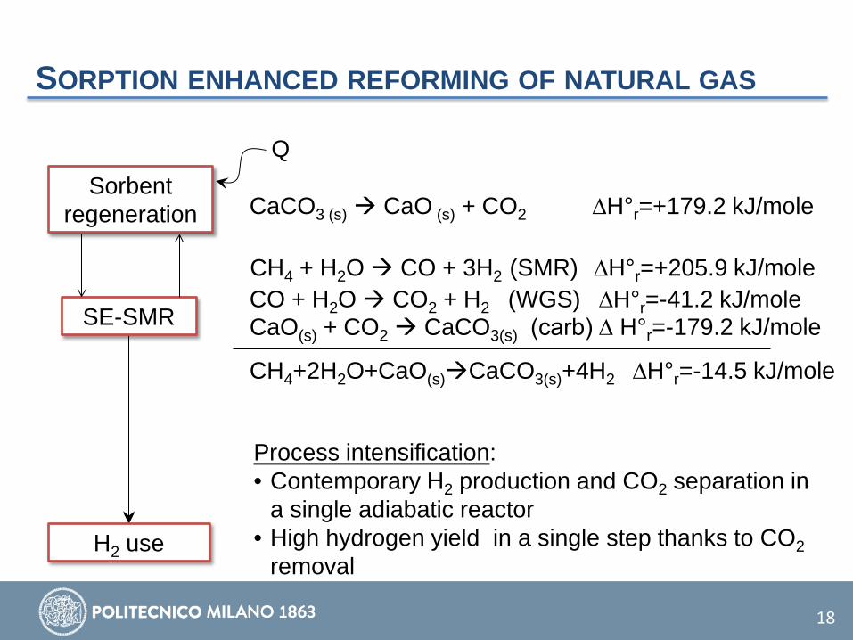
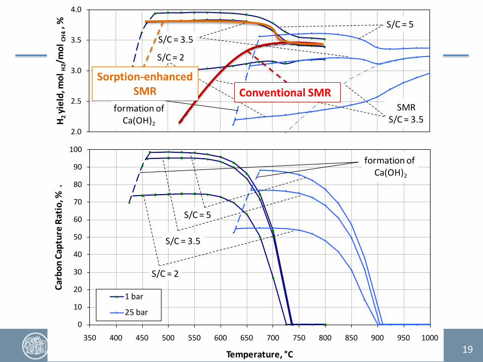
SORPTION ENHANCED REFORMING OF NATURAL GAS
CH4 + H2O CO + 3H2 (SMR) ∆H°r=+205.9 kJ/mole CO + H2O CO2 + H2 (WGS) ∆H°r=-41.2 kJ/mole
SE-SMR CaO(s) + CO2 CaCO3(s) (carb) ∆ H°r=-179.2 kJ/mole
CH4+2H2O+CaO(s)CaCO3(s)+4H2 ∆H°r=-14.5 kJ/mole
Sorbent regeneration CaCO3 (s) CaO (s) + CO2 ∆H°r=+179.2 kJ/mole
Q
H2 use
Process intensification: • Contemporary H2 production and CO2 separation in
a single adiabatic reactor • High hydrogen yield in a single step thanks to CO2
removal
18
0
10
20
30
40
50
60
70
80
90
100
350 400 450 500 550 600 650 700 750 800 850 900 950 1000
Carb
on C
aptu
re R
atio
, % .
Temperature, °C
1 bar
25 bar
S/C = 5
S/C = 3.5
S/C = 2
formation of Ca(OH)2
2.0
2.5
3.0
3.5
4.0
H 2yi
eld,
mol
H2/
mol
CH4
, %
formation of Ca(OH)2
S/C = 2
S/C = 3.5
SMRS/C = 3.5
S/C = 5
Conventional SMR Sorption-enhanced
SMR
19

Sorption enhanced reforming works nicely in the hydrogen production step. Challenges are in the sorbent regeneration step.
• Hydrogen should be produced at high pressure because hydrogen compression is very energy expensive, BUT sorbent regeneration at high pressure requires too high temperatures for the stability of sorbent and catalyst
SORPTION ENHANCED REFORMING OF NATURAL GAS
• Packed beds allow easier pressure swing, BUT heat management with high reaction heat is challenging
• Fluidized beds allow easier heat management (uniform temperatures in reactors), BUT pressure swing is very challenging (especially at high temperatures)
• Hydrogen may be produced in interconnected fluidized beds at low pressure to avoid pressure swing, BUT hydrogen compression is needed for most industrial uses
20
• Regeneration requires temperatures of 850-900°C at atmospheric pressure
SORPTION ENHANCED REFORMING OF NATURAL GAS
High temperature heat has to be provided to the calciner
• Oxyfuel combustion is an option, BUT oxygen production is expensive and may lead to hot spots, causing materials degradation
• Indirect heating of the calciner is another option, BUT very high temperature heat transfer surfaces are needed
In addition to process development, materials development is key challenge of Sorption Enhanced Reforming processes.
21
• Heating by an additional high temperature CLC loop is also an option, BUT an additional CLC material is needed and increased process complexity

SUMMARY
• High temperature sorbent systems for post-combustion capture • Integration in power plants • Integration in cement plants
• High temperature sorbent systems for pre-combustion capture
• Sorption enhanced reforming for power generation and hydrogen production
• Sorption enhanced WGS in power plants and integrated steel mills
• Sorption enhanced gasification for biofuels production
• Conclusions
22
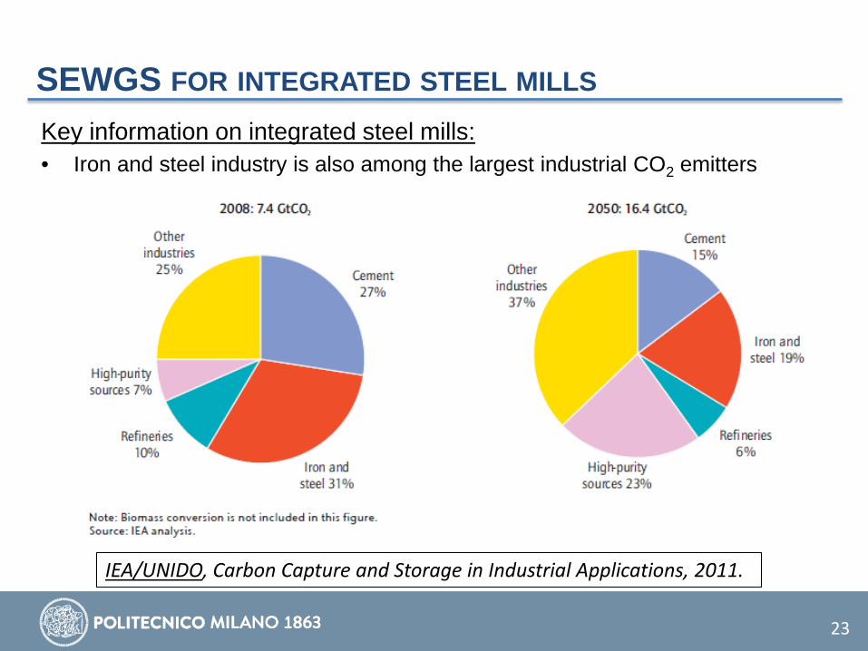
SEWGS FOR INTEGRATED STEEL MILLS Key information on integrated steel mills: • Iron and steel industry is also among the largest industrial CO2 emitters
23
IEA/UNIDO, Carbon Capture and Storage in Industrial Applications, 2011.

SEWGS FOR INTEGRATED STEEL MILLS
How does an integrated steel mill work:
24
Coke produced in coke oven
Iron reduced by coke in a blast furnace producing pig iron
Carbon and impurities removed in BOF by oxygen injection
Excess process gases are burned in a power plant (steam or combined cycle)

SEWGS FOR INTEGRATED STEEL MILLS
CO2 emissions:
25
Power plant: 40-70%
Hot stoves: 15-30%
Coke oven: 15-20%
Sinter plant and lime kiln:
10-25%
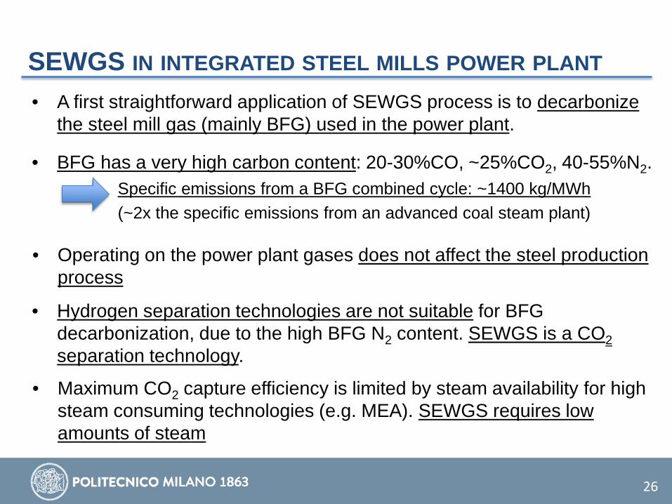
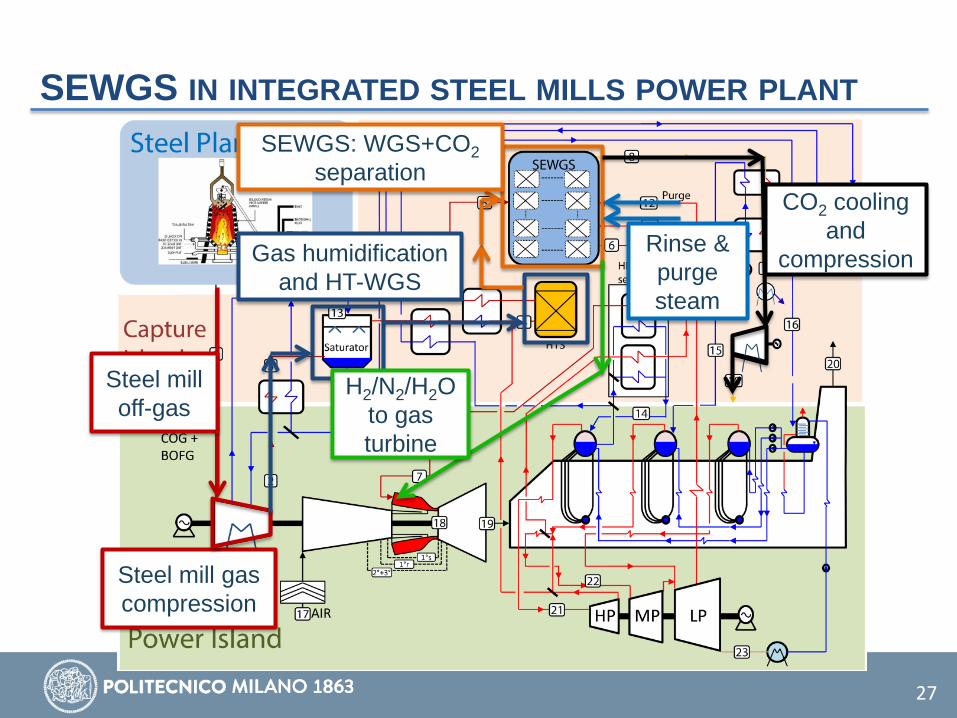
SEWGS IN INTEGRATED STEEL MILLS POWER PLANT
26
• A first straightforward application of SEWGS process is to decarbonize the steel mill gas (mainly BFG) used in the power plant.
• BFG has a very high carbon content: 20-30%CO, ~25%CO2, 40-55%N2. Specific emissions from a BFG combined cycle: ~1400 kg/MWh (~2x the specific emissions from an advanced coal steam plant)
• Operating on the power plant gases does not affect the steel production process
• Hydrogen separation technologies are not suitable for BFG decarbonization, due to the high BFG N2 content. SEWGS is a CO2 separation technology.
• Maximum CO2 capture efficiency is limited by steam availability for high steam consuming technologies (e.g. MEA). SEWGS requires low amounts of steam
SEWGS IN INTEGRATED STEEL MILLS POWER PLANT
27
Steel mill off-gas
Steel mill gas compression
Gas humidification and HT-WGS
SEWGS: WGS+CO2 separation
CO2 cooling and
compression Rinse & purge steam
H2/N2/H2O to gas turbine

SEWGS IN INTEGRATED STEEL MILLS POWER PLANT
28
• With conventional MEA process, maximum CO2 avoidance is limited by steam shortage, while MDEA and SEWGS can achieve ~90% of CO2 capture efficiency
Power balance, MWe Ref, no capt.
Post-comb. MEA capt.
Pre-comb. MDEA capt. SEWGS
Net efficiency, %LHV 52.3 38.6 34.6 37.7 CO2 emission, kg/MWhe 1339 871 147 149 CO2 avoided, % - 35.0 89.3 88.9 SPECCA, MJLHV/kgCO2
- 5.20 2.94 2.24
Gazzani et al., 2015. CO2 capture in integrated steelworks by commercial-ready technologies and sewgs process. Int. J. Greenh. Gas Control, 41, 249-267.
• SEWGS allows achieving much higher efficiency and better SPECCA (specific primary energy consumption for CO2 avoided).
SUMMARY
• High temperature sorbent systems for post-combustion capture • Integration in power plants • Integration in cement plants
• High temperature sorbent systems for pre-combustion capture
• Sorption enhanced reforming for power generation and hydrogen production
• Sorption enhanced WGS in power plants and integrated steel mills
• Sorption enhanced gasification for biofuels production
• Conclusions
29
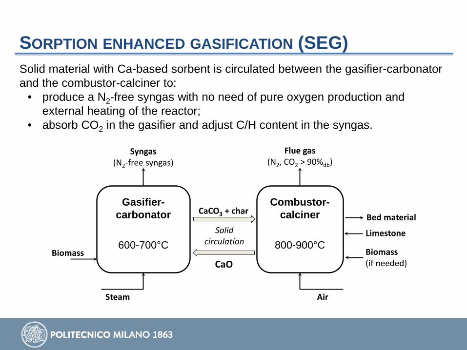
Solid material with Ca-based sorbent is circulated between the gasifier-carbonator and the combustor-calciner to:
• produce a N2-free syngas with no need of pure oxygen production and external heating of the reactor;
• absorb CO2 in the gasifier and adjust C/H content in the syngas.
Gasifier-carbonator
600-700°C
Combustor-calciner
800-900°CBiomass
Steam
Syngas(N2-free syngas)
CaO
CaCO3 + char
Solid circulation
Air
Biomass (if needed)
Flue gas(N2, CO2 > 90%db)
Limestone
Bed material
SORPTION ENHANCED GASIFICATION (SEG)
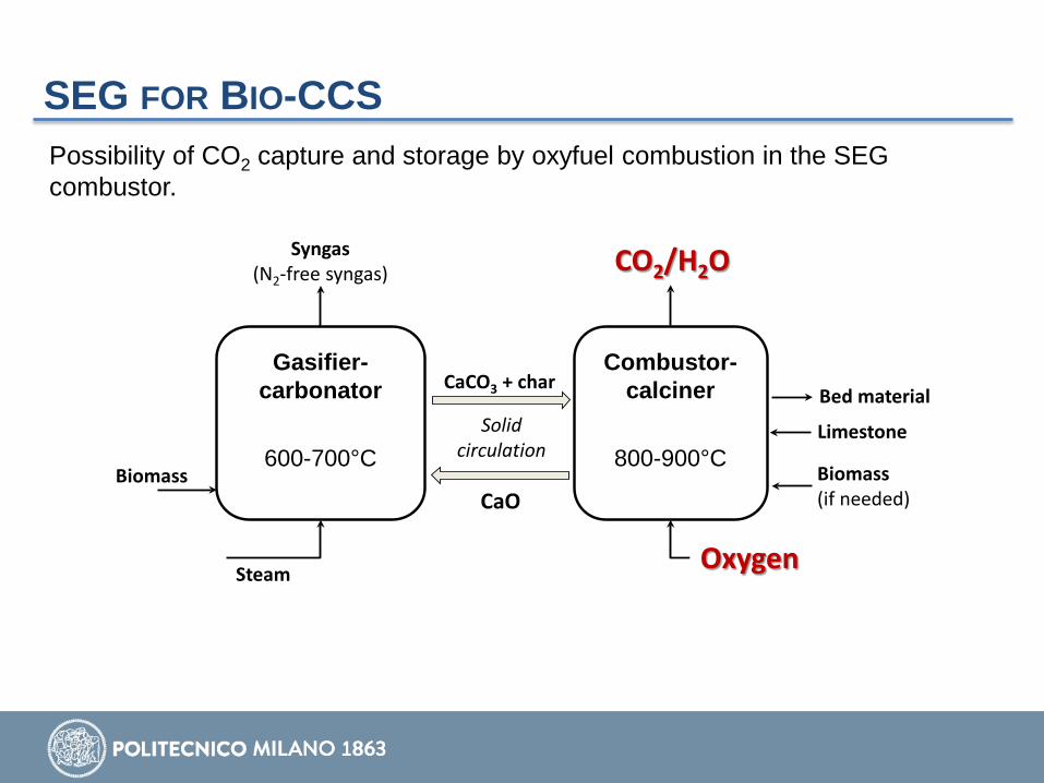
SEG FOR BIO-CCS Possibility of CO2 capture and storage by oxyfuel combustion in the SEG combustor.
Gasifier-carbonator
600-700°C
Combustor-calciner
800-900°CBiomass
Steam
Syngas(N2-free syngas)
CaO
CaCO3 + char
Solid circulation
Air
Biomass (if needed)
Flue gas(N2, CO2 > 90%db)
Limestone
Bed material
Oxygen
CO2/H2O

SORPTION ENHANCED GASIFICATION (SEG)
0,0
0,5
1,0
1,5
2,0
2,5
3,0
3,5
4,0
4,5
0,0
0,5
1,0
1,5
2,0
2,5
3,0
3,5
4,0
4,5
0,0 0,5 1,0 1,5 2,0 2,5 3,0 3,5 4,0 4,5M
=(H 2-
CO2)
/(CO
+CO
2) m
olar
ratio
H 2/CO
mol
ar ra
tio
Ca/C ratio at gasifier inlet
FT (F
e-ca
taly
st)
/MeO
H/DM
E
Met
hane
(act
ive
WGS
cat
alys
t)
FT (Co-catalyst)
Methane (inactive WGS catalyst)
By controlling the SEG process parameters (solid circulation, Ca/C ratio in the gasifier, gasifier temperature, S/C ratio), syngas composition can be adjusted to match with the downstream synthesis process.
Martínez et al., 2016. Energy, 113, 615-630.

SEG + SEDMES PROCESSES FOR BIO-DME
Gasification process
Biomass Tar/PM removal
WGS unit
CO2 separation
H2S separation
MeOH synthesis
DME synthesis
DME MeOH separation
MeOH DME separation
MeOH recycle H2/CO/CO2 recycle
SEG process
Biomass
air Tar/PM removal
H2S separation
SE-DME synthesis
DME DME separation
Optional CO recycle (smaller for given yield)
Biomass to DME by FLEDGED process
Biomass to DME with conventional process
ASU
air
Air (if ind. gas)
O2
Steam
Steam
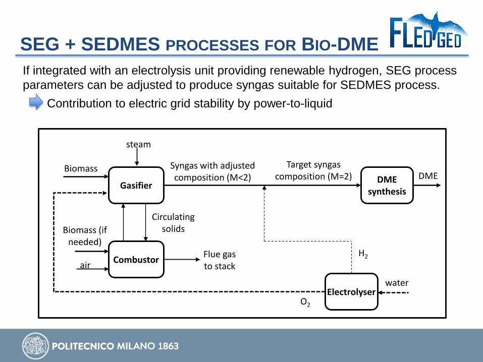
SEG + SEDMES PROCESSES FOR BIO-DME If integrated with an electrolysis unit providing renewable hydrogen, SEG process parameters can be adjusted to produce syngas suitable for SEDMES process. Contribution to electric grid stability by power-to-liquid
Gasifier DME synthesis
Electrolyser
DMESyngas with adjusted composition (M<2)
Biomass
H2
O2
Combustor
Biomass (if needed)
Flue gas to stackair
steam
water
Target syngas composition (M=2)
Circulating solids

CONCLUSIONS
35
• High temperature CO2 sorbent systems are applicable through a wide variety of process integration options
• Promising application of post-combustion Ca-looping processes are power plants with improved flexibility and cement plants. For cement plants, technical demonstration is needed for the highly integrated Ca-looping process (TRL2-3).
• Sorption enhanced reforming with high temperature sorbent systems appears as the preferable option for natural gas plants. A wide variety of possible (still immature: TRL3-4) process integration options exists, to be assessed in conjunction with material development.
• SEWGS process (now at TRL4-5) is ready for demonstration in integrated steel mills (TRL6). This appears as the most promising application for SEWGS that may open further opportunities for application in power plants and hydrogen plants.
• SEG process is not new, but flexible operation to provide electric grid service has to be demonstrated. This represents an opportunity in electric mix with high share of intermittent renewables.


www.stepwise.eu
37
www.ascentproject.eu www.sintef.no/projectweb
/cemcap/
This presentation is part of projects that have received funding from the European Union’s FP7 programme (Ascent, grant agreement No. 608512), Horizon 2020 research and innovation programme (CEMCAP, g.a. No. 641185, STEPWISE, g.a. No.640769, FLEDGED, g.a. No. 727600) and RFCS (FlexiCaL, g.a. 709629).
ACKNOWLEDGMENTS
www.fledged.eu @FledgedProject
www.flexical.eu


