Download - COE 202: Digital Logic Design Sequential Circuits Part 3 KFUPM Courtesy of Dr. Ahmad Almulhem

COE 202: Digital Logic DesignSequential Circuits
Part 3
KFUPM
Courtesy of Dr. Ahmad Almulhem

Objectives
• Design of Synchronous Sequential Circuits• Procedure• Examples
• Important Design Concepts• State Reduction and Assignment
KFUPM

Design of Synchronous Sequential Circuits
• The design of a clocked sequential circuit starts from a set of specifications and ends with a logic diagram (Analysis reversed!)
• Building blocks: flip-flops, combinational logic• Need to choose type and number of flip-flops• Need to design combinational logic together with flip-
flops to produce the required behavior• The combinational part is
• flip-flop input equations• output equations
KFUPM

Design of Synchronous Sequential Circuits
Design Procedure:• Obtain a state diagram from the word description
• State reduction if necessary
• Obtain State Table• State Assignment• Choose type of flip-flops• Use FF’s excitation table to complete the table
• Derive state equations• Obtain the FF input equations and the output equations• Use K-Maps
• Draw the circuit diagram
KFUPM

Step1: Obtaining the State Diagram
•A very important step in the design procedure.
•Requires experience!
Example: Design a circuit that detects a sequence of three consecutive 1’s in a string of bits coming through an input line (serial bit stream)
KFUPM

Step1: Obtaining the State Diagram
•A very important step in the design procedure.
•Requires experience!
Example: Design a circuit that detects a sequence of three consecutive 1’s in a string of bits coming through an input line (serial bit stream)
KFUPM

Step2: Obtaining the State Table
•Assign binary codes for the states
•We choose 2 D-FF
•Next state specifies what should be the input to each FF
Example: Design a circuit that detects a sequence of three consecutive 1’s in a string of bits coming through an input line (serial bit stream)
KFUPM

Step3: Obtaining the State Equations
Using K-Maps
•A(t + 1) = DA = ∑(3,5,7) = A x + B x
•B(t + 1) = DB = ∑(1,5,7) = A x + B’ x
•y = ∑(6,7) = A B
Example: Design a circuit that detects a sequence of three consecutive 1’s in a string of bits coming through an input line (serial bit stream)
KFUPM

Step4: Draw Circuits
Using K-Maps
•A(t + 1) = DA = ∑(3,5,7) = A x + B x
•B(t + 1) = DB = ∑(1,5,7) = A x + B’ x
•y = ∑(6,7) = A B
Example: Design a circuit that detects a sequence of three consecutive 1’s in a string of bits coming through an input line (serial bit stream)
KFUPM

Design with Other types of FF
• In designing with D-FFs, the input equations are obtained from the next state (simple!)
• It is not the case when using JK-FF and T-FF !
• Excitation Table: Lists the required inputs that will cause certain transitions.• Characteristic tables used for analysis, while excitation tables
used for design
KFUPM
+ +
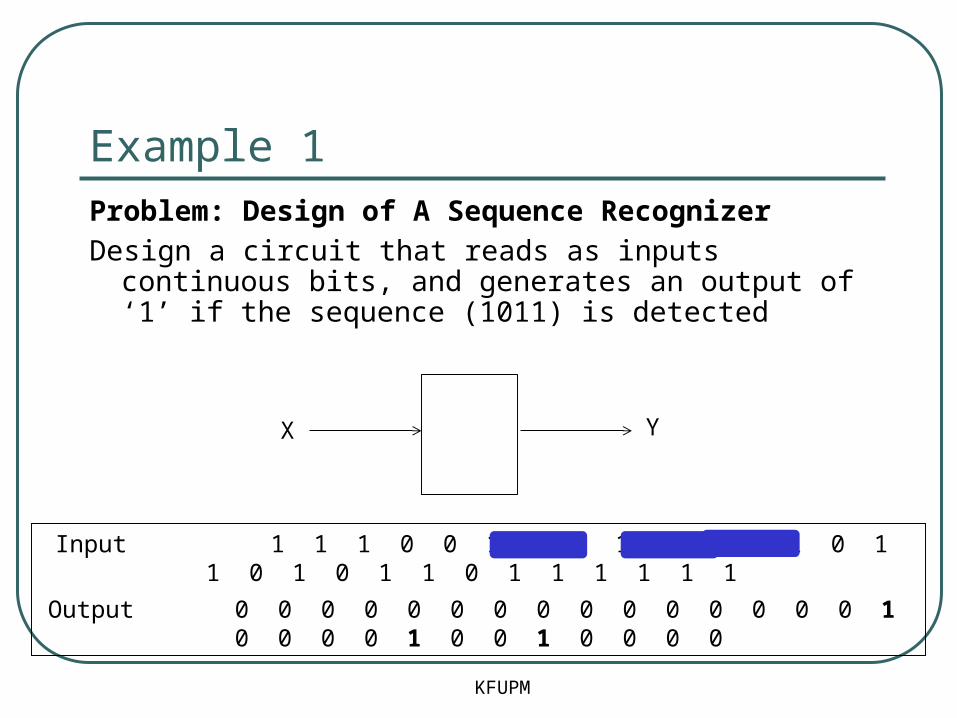
Example 1Problem: Design of A Sequence Recognizer
Design a circuit that reads as inputs continuous bits, and generates an output of ‘1’ if the sequence (1011) is detected
Input 1 1 1 0 0 1 0 0 1 0 0 1 1 0 1 1 0 1 0 1 1 0 1 1 1 1 1 1
Output 0 0 0 0 0 0 0 0 0 0 0 0 0 0 0 1 0 0 0 0 1 0 0 1 0 0 0 0
KFUPM
X Y
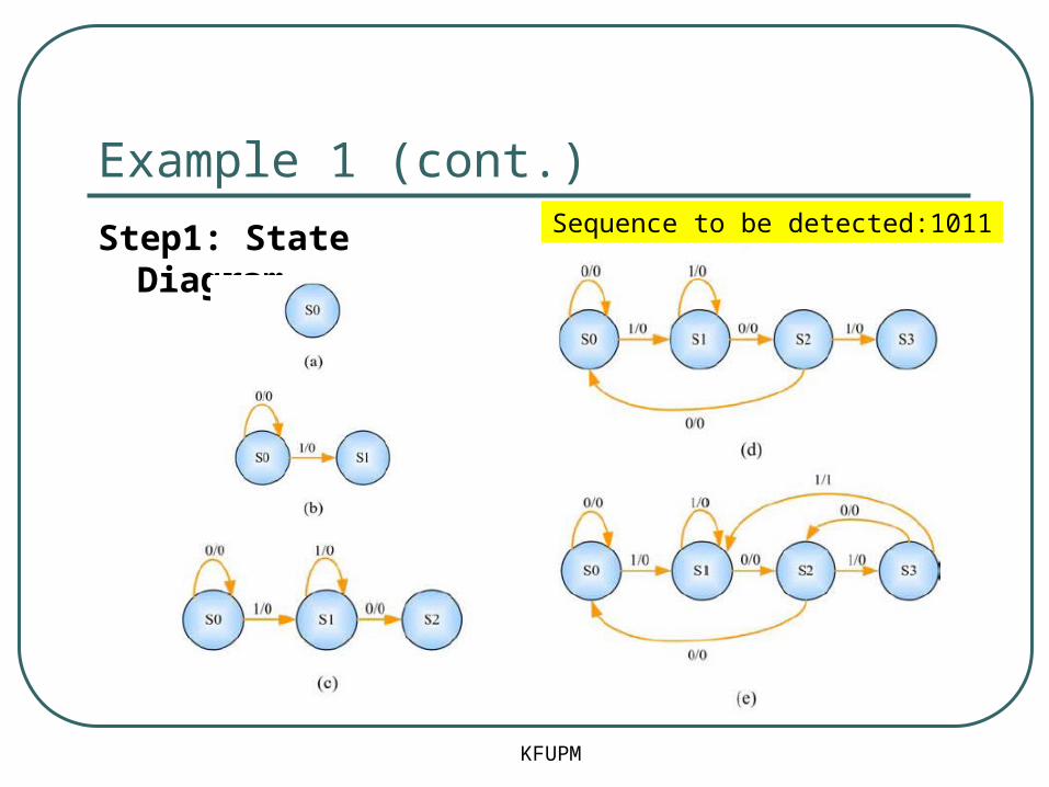
Example 1 (cont.)
Step1: State Diagram
KFUPM
Sequence to be detected:1011

Example 1 (cont.)
KFUPM
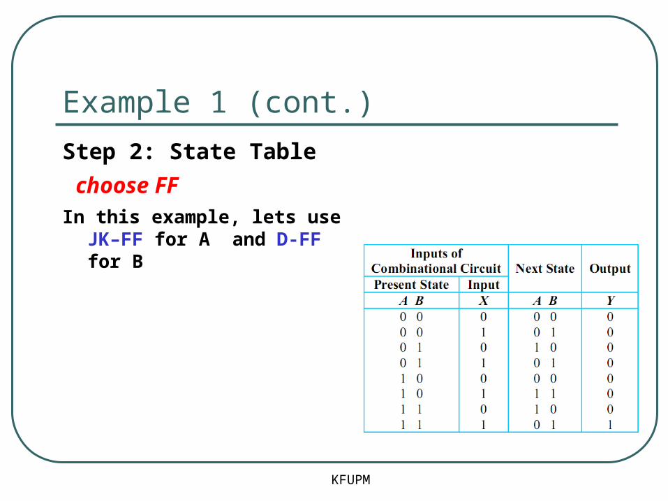
Step 2: State Table
OR

Example 1 (cont.)
KFUPM
Step 2: State Table
state assignment
Q: How many FF?
log2(no. of states)
Example 1 (cont.)
KFUPM
Step 2: State Table
choose FFIn this example, lets use JK–FF
for A and D-FF for B
Example 1 (cont.)
KFUPM
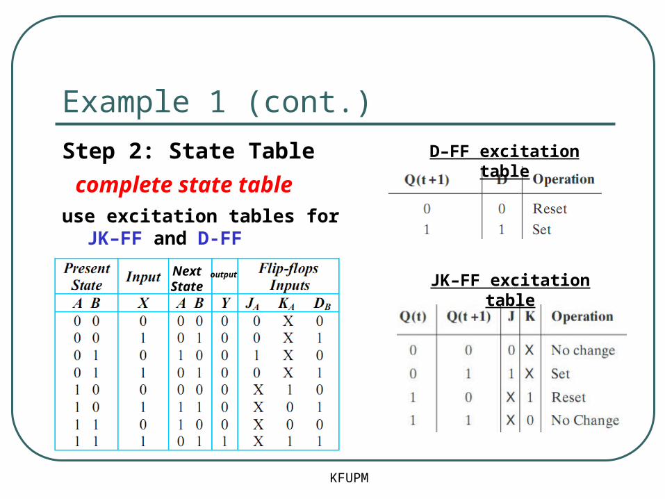
Step 2: State Table
complete state tableuse excitation tables for JK–FF
and D-FF
D–FF excitation table
JK–FF excitation tableNextState
output

Example 1 (cont.)
KFUPM
Step 3: State Equations
use k-map
JA = BX’
KA = BX + B’X’
DB = X
Y = ABX’

Example 1 (cont.)
KFUPM
Step 4: Draw Circuit
JA = BX’
KA = BX + B’X’
DB = X
Y = ABX’

Example 2
KFUPM
Problem: Design of A 3-bit Counter
Design a circuit that counts in binary form as follows 000, 001, 010, … 111, 000, 001, …

Example 2 (cont.)
KFUPM
Step1: State Diagram
- The outputs = the states
- Where is the input?
- What is the type of this sequential circuit?

Example 2 (cont.)
KFUPM
Step2: State Table
No need for state assignment here
Example 2 (cont.)
KFUPM
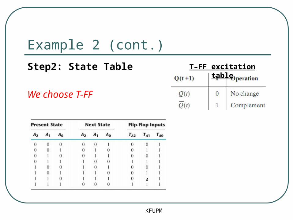
Step2: State Table
We choose T-FF
T–FF excitation table
0
Example 2 (cont.)
KFUPM
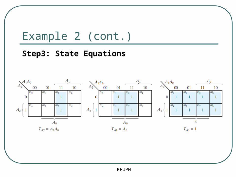
Step3: State Equations
Example 2 (cont.)
KFUPM
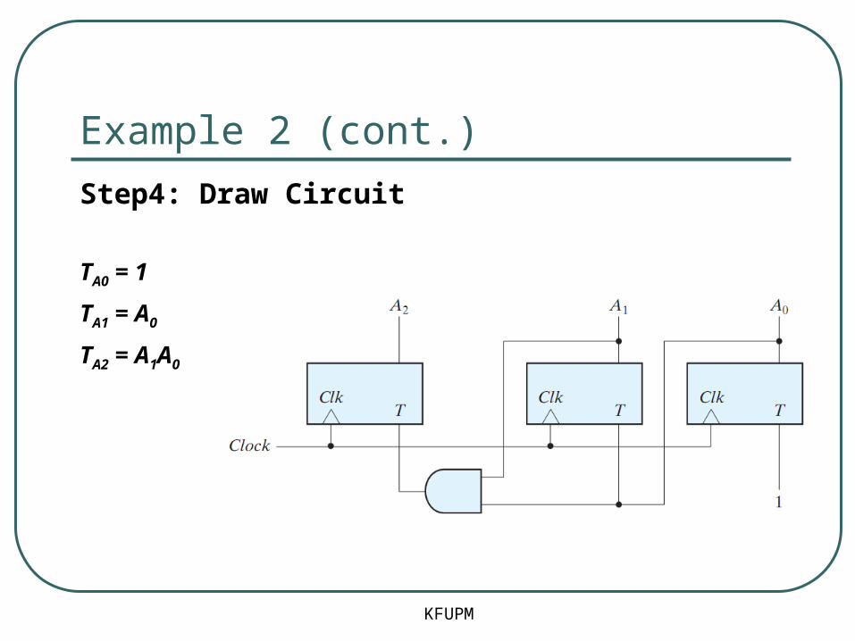
Step4: Draw Circuit
TA0 = 1
TA1 = A0
TA2 = A1A0

Example 3
KFUPM
Problem: Design of A Sequence Recognizer
Design a Moore machine to detect the sequence (111). The circuit has one input (X) and one output (Z).

Example 3 (cont.)
KFUPM
Step1: State Diagram Sequence to be detected:111
S0/0 S1/0 S2/0 S3/1
1
0
1 1
0
0
0 1

Example 3 (cont.)
KFUPM
Step2: State TableUse binary encoding
Use JK-FF and D-FFS0/0 S1/0 S2/0 S3/1
1
0
1 1
0
0
0 1

Example 3 (cont.)
KFUPM
Step4: Draw CircuitFor step3, use k-maps as
usual
JA = XB
KA = X’
DB = X(A+B)
Z = A.B
Example 3 (cont.)
KFUPM
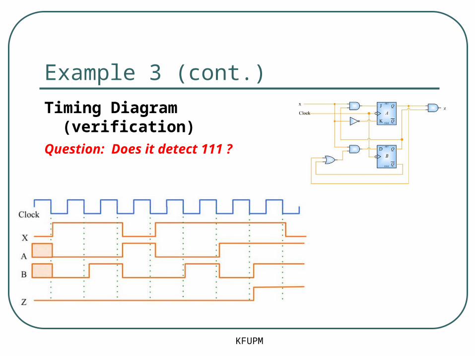
Timing Diagram (verification)Question: Does it detect 111 ?
Example 4
KFUPM
N
S
EW
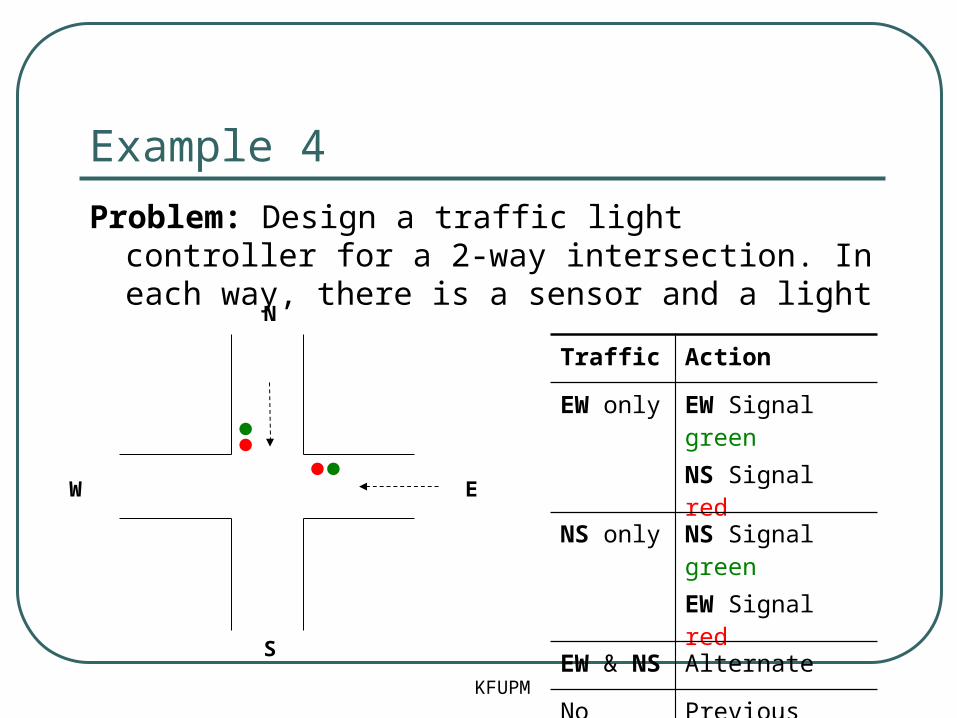
Traffic Action
EW only EW Signal greenNS Signal red
NS only NS Signal greenEW Signal red
EW & NS Alternate
No traffic Previous state
Problem: Design a traffic light controller for a 2-way intersection. In each way, there is a sensor and a light

Example 4 (cont.)
KFUPM
EW / 10NS / 01
INPUTS
• Sensors X1, X0
X0: car coming on NSX1 : car coming on EW
11, 10
00, 01 00, 10
11, 01
OUTPUTS
• Light S1, S0
S0 : NS is greenS1 : EW is green
STATES
• NS: NS is green• EW: EW is green
Step1: State Diagram
Example 4 (cont.)
Exercise: Complete the design using:• D-FF• JK-FF• T-FF
KFUPM

Example 5
Problem: Design Up/Down counter with Enable
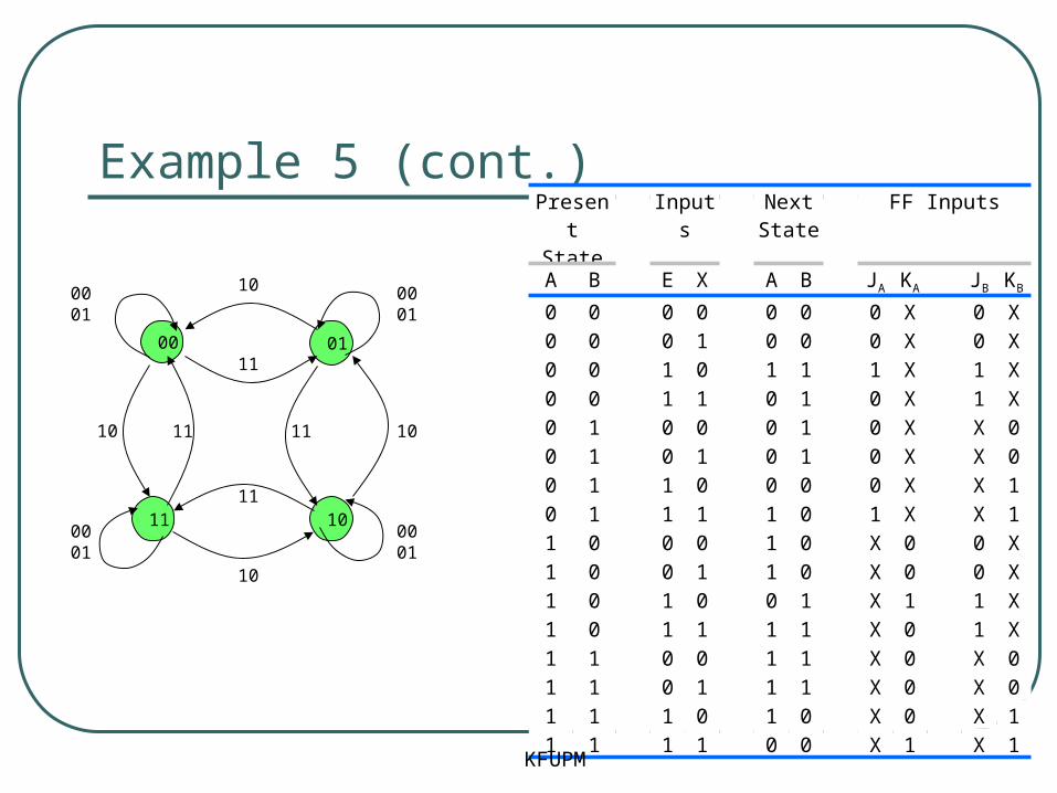
Design a sequential circuit with two JK flip-flops A and B and two inputs X and E. If E = 0, the circuit remains in the same state, regardless of the input X. When E = 1 and X = 1, the circuit goes through the state transitions from 00 to 01 to 10 to 11, back to 00, and then repeats. When E = 1 and X = 0, the circuit goes through the state transitions from 00 to 11 to 10 to 01, back to 00 and then repeats.
KFUPM
Example 5 (cont.)
00 01
1011
0001
10 11 1011
10
11
11
0001
0001
10
0001
Present State
Inputs
Next State
FF Inputs
A B E X A B JA KA JB KB
0 0 0 0 0 0 0 X 0 X0 0 0 1 0 0 0 X 0 X0 0 1 0 1 1 1 X 1 X0 0 1 1 0 1 0 X 1 X0 1 0 0 0 1 0 X X 00 1 0 1 0 1 0 X X 00 1 1 0 0 0 0 X X 10 1 1 1 1 0 1 X X 11 0 0 0 1 0 X 0 0 X1 0 0 1 1 0 X 0 0 X1 0 1 0 0 1 X 1 1 X1 0 1 1 1 1 X 0 1 X1 1 0 0 1 1 X 0 X 01 1 0 1 1 1 X 0 X 01 1 1 0 1 0 X 0 X 11 1 1 1 0 0 X 1 X 1
KFUPM

Example 5 (cont.)
JA = BEX + B’EX’
EXAB
00 01 11 10
00 x x x x
01 x x x x
11 0 0 1 0
10 0 0 0 1KA = BEX + B’EX’
EXAB
00 01 11 10
00 0 0 0 1
01 0 0 1 0
11 x x x x
10 x x x x
JB = E
EXAB
00 01 11 10
00 x x x x
01 0 0 1 1
11 0 0 1 1
10 x x x XKB = E
EXAB
00 01 11 10
00 0 0 1 1
01 x x x x
11 x x x x
10 0 0 1 1
Y
X
JA
C
A
A’KA
E
clock
JB
C
B
B’KB
KFUPM

More Design Examples
• More design examples can be found at• Homework 5• Textbook• Course CD• Google
KFUPM

State Reduction
• Two sequential circuits may exhibits the same input-output behavior, but have a different number of states
• State Reduction: The process of reducing the number of states, while keeping the input-output behavior unchanged.
• It results in less Flip flops• It may increase the combinational logic!
KFUPM

State Reduction (Example)
Is it possible to reduce this FSM?
• How many states?
• How many input/outputs?
Notes:
• we use letters to denote states rather than binary codes
• we only consider input/output sequence and transitions
KFUPM

State Reduction (Example)
KFUPM
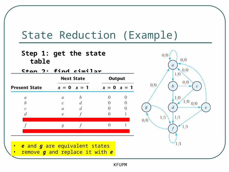
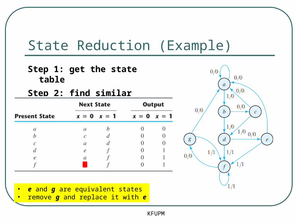
Step 1: get the state table
State Reduction (Example)
KFUPM
Step 1: get the state table
Step 2: find similar states
• e and g are equivalent states• remove g and replace it with e
State Reduction (Example)
KFUPM
Step 1: get the state table
Step 2: find similar states
• e and g are equivalent states• remove g and replace it with e
State Reduction (Example)
KFUPM
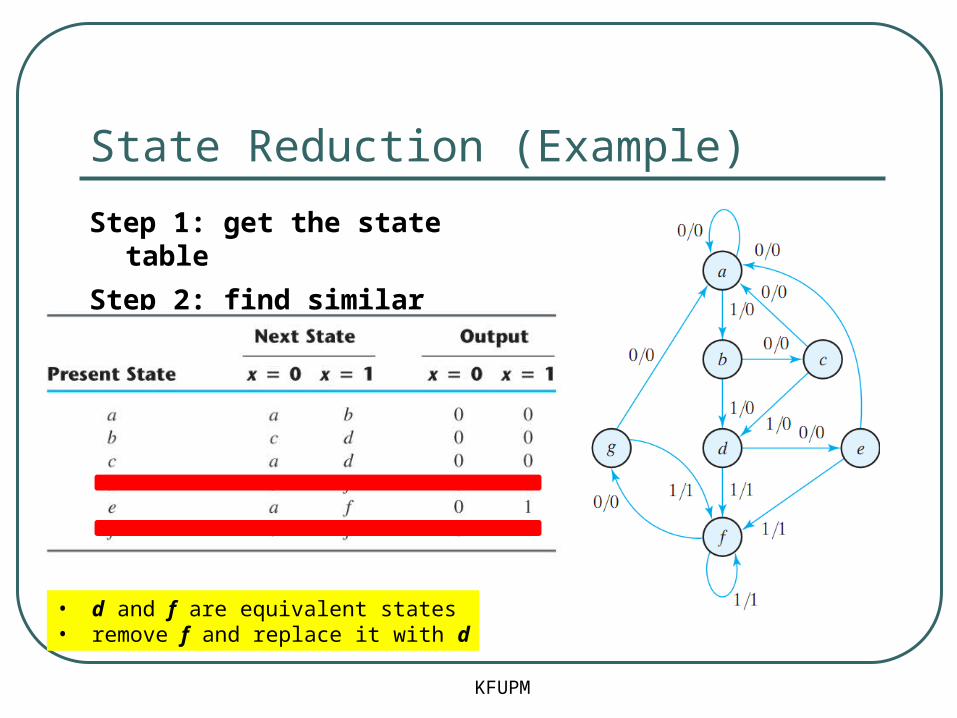
Step 1: get the state table
Step 2: find similar states
• d and f are equivalent states• remove f and replace it with d
State Reduction (Example)
KFUPM
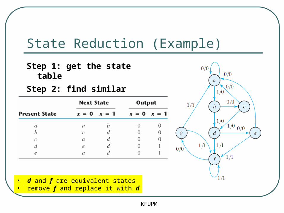
Step 1: get the state table
Step 2: find similar states
• d and f are equivalent states• remove f and replace it with d

State Reduction (Example)
KFUPM
Reduced FSM
Verify sequence:
State a a b c d e f f g f
input 0 1 0 1 0 1 1 0 1
output 0 0 0 0 0 1 1 0 1

State Assignmnet
KFUPM
State Assignment: Assign unique binary codes to the states
• For m states, we need log2 m bits (FF)
Example• Three Possible Assignments:

Summary
• To design a synchronous sequential circuit:• Obtain a state diagram
• State reduction if necessary
• Obtain State Table• State Assignment
• Choose type of flip-flops
• Use FF’s excitation table to complete the table
• Derive state equations• Use K-Maps
• Obtain the FF input equations and the output equations
• Draw the circuit diagram
KFUPM


