
NASA Technical Memorandum 107188
/'/// -- _ /
Combining Acceleration and Displacement
Dependent Modal Frequency Responses
Using an MSC/NASTRAN DMAP Alter
Alan R. Barnett and Timothy W. Widrick
Analex CorporationBrook Park, Ohio
Damian R. Ludwiczak
Lewis Research Center
Cleveland, Ohio
Prepared for the1996 World Users' Conference
sponsored by The MacNeal-Schwendler Corporation
Los Angeles, Califomia, June 3-7, 1996
National Aeronautics and
Space Administration
https://ntrs.nasa.gov/search.jsp?R=19960017265 2018-04-22T06:24:09+00:00Z

Trade names or roanufacna_' names ale used in this report for identificalkmonly. This usage does not constitute an official ez_lo_e_ent, either expressed
o¢ implied, by the National Ae_onaufi_ and Space Administration.

COMBINING ACCELERATION AND DISPLACEMENT
DEPENDENT MODAL FREQUENCY RESPONSES
USING AN MSC/NASTRAN DMAP ALTER
Alan R. Barnett and Timothy W. Widrick
Analex Corporation
3001 Aerospace ParkwayBrook Park, Ohio 44142
Damian R. Ludwiczak
National Aeronautics and Space AdministrationLewis Research Center
Cleveland, Ohio 44135
Abstract
Solving for dynamic responses of free-free launch vehicle / spacecraft systems acted upon by buffeting winds is
commonly performed throughout the aerospace industry. Due to the unpredictable nature of this wind loading event,
these problems are typically solved using frequency response random analysis techniques. To generate dynamic
responses for spacecraft with statically-indeterminate interfaces, spacecraft contractors prefer to develop models whichhave response transformation matrices developed for mode acceleration data recovery. This method transforms
spacecraft boundary accelerations and displacements into internal responses. Unfortunately, standardMSCfNASTRAN modal frequency response solution sequences cannot be used to combine acceleration- and
displacement-dependent responses required for spacecraft mode acceleration data recovery. External user-written
computer codes can be used with MSC/NASTRAN output to perform such combinations, but these methods can be
labor and computer resource intensive. Taking advantage of the analytical and computer resource efficienciesinherent within MSC/NASTRAN, a DMAP Alter has been developed to combine acceleration- and displacement-
dependent modal frequency responses for performing spacecraft mode acceleration data recovery. The Alter has been
used successfully to efficiently solve a common aerospace buffeting wind analysis.

COMBINING ACCELERATION AND DISPLACEMENT
DEPENDENT MODAL FREQUENCY RESPONSES
USING AN MSC/NASTRAN DMAP ALTER
Alan R. Barnett and Timothy W. Widrick
Analex Corporation
3001 Aerospace ParkwayBrook Park, Ohio 44142
Damian R. Ludwiczak
National Aeronautics and Space AdministrationLewis Research Center
Cleveland, Ohio 44135
Abbreviations
Nomenclature
Ma_k_
DMAP Direct Matrix Abstraction a Accelerations
Program B Damping
DOF Degree-of-freedom G Physical transformation
ELV Expendable Launch I IdentityVehicle K Stiffness
FRF Frequency Response M MassFunction P Applied loads
OTM Output Transformation R Physical responses
Matrix u Displacements
RMS Root-mean-square v VelocitiesModal transformation
Set Notation
a a-set (assembled DOIO
A Acceleration-dependent
b b-set (physical boundary DOF)
C Acceleration- & Displacement-
dependent
D Displacement-dependentg g-set (global DOF)
h h-set (system modal DOF)
i Applied loads index
j Output frequency index
Introduction
Solving for dynamic responses of free-free launch vehicle / spacecraft systems acted upon by buffeting winds is
commonly performed throughout the aerospace industry. Due to the unpredictable nature of this wind loading event,
these problems are typically solved using frequency response random analysis techniques. Solving for coupled
system frequency domain responses is commonly performed at the coupled system modal DOF level in order to take
advantage of analytical efficiencies. Modal frequency response analysis is offered in MSC/NASTRAN via Solution
Sequence 71 [1].
Once the coupled system frequency domain responses are solved for, spacecraft responses can be generated. To
generate dynamic responses for spacecraft with statically-indeterminate interfaces, spacecraft contractors prefer to
develop models which have response transformation matrices developed for the mode acceleration method of data
recovery [2]; a method used to transform spacecraft boundary accelerations and displacements into internal responses.
Unfortunately, while standard MSC/NASTRAN Solution Sequence 71 can be used to generate acceleration- or
displacement-dependent responses, it cannot be used to combine acceleration- and displacement-dependent responses
required for spacecraft mode acceleration data recovery.

Onemethodforperformingspacecraftmodeaccelerationdatarecoveryduringfrequencydomainbuffetingwindanalysesistouseexternaluser-writtencomputercodesthatprocessMSC/NASTRANoutput.Unfortunately,thesemethodscanbelaborandcomputerresourceintensive.GiventheanalyticalandcomputerresourceefficienciesinherentwithinMSC/NASTRAN,it isadvantageoustousethecodedirectly.Hence,theobjectiveofthisworkwastodevelopamethodologywithinMSC/NASTRANforperformingspacecraftmodeaccelerationdatarecoveryduringmodalfrequencyresponseanalyses.Tothisend,anMSC/NASTRANDMAPAlterhasbeendevelopedforSolutionSequence71,andit hasbeenusedsuccessfullytoefficientlysolveanELV/spacecraftfrequencydomainbuffetingwind analysis.
The underlying theory of spacecraft mode acceleration data recovery during MSC/NASTRAN modal frequency
response analysis is detailed in the next section. Implementation of the theory within an MSC/NASTRAN DMAP
Alter is then explained in a subsequent section. Lastly, spacecraft mode acceleration data recovery is performed
during an ELV/spacecraft frequency domain buffeting wind analysis to demonstrate the accuracy of using the new
Alter versus using an external user-written computer code.
Theory
Let all physical DOF of a free-free coupled ELV/spacecraft system be defined as g-set DOF. Neglecting damping,
the residual level coupled system equations are
[Mgg] [ag] + [K_] [ug] -- [Pg] (1)
After accounting for DOF defined via multi-point and single-point constraints, the system equations are reduced from
g-set size to a-set size [3]; hence,
[Mj[a a] + [K ][u,] -- [Pa] (2)
To solve the coupled system frequency response equations in modal coordinates, the coupled system mode shapes
are used to transform the coupled system equations from physical space to modal space. As implemented within
MSCfNASTRAN Solution Sequence 71 [3], the coupled system modal frequency response equations for a je output
frequency, c0j, for an it_ applied load are
if. 0 iO)IMp] {ah( j)} + [B_] {v_(coj)} + [K_ {uh( j)} -- {P_(%)} (3)
where system damping has been included via [B_]. The modal applied loads {P_(o_j)} are "unit" loads so that themodal solutions are transfer functions between the actual applied loads and the modal responses. This facilitates
MSC/NASTRAN data recovery operations. Assuming there are "n" number of output frequencies being requested
for each applied load, the modal displacements for an i_ applied load are
(4)
Note that the modal displacements are complex quantities and are commonly referred to as frequency response
functions (FRFs). Next, assuming there are "m" number of loads being applied to the system, the modal
displacement FRFs corresponding to each load are appended to form a matrix of all modal displacement FRFs
Given the system modal displacement FRFs, the boundary displacement FRFs for any component of the system can

then be generated. The component boundary displacement FRFs for a j_ frequency for an it applied load are
{u2(%)} -- [a,.3 {u_(%)} (6)
where [_] is the partition of the coupled system mode shapes corresponding to the component boundary (a-se0DOF. These DOF are generally comprised of both component physical and generalized DOF. Because the problemat hand is set in the frequency domain, solving for acceleration FRFs is simple once displacement FRFs are knowndue to the properties of the Fourier Transform [41. Given the system modal displacement FRFs, component a-setDOF acceleration FRFs for a j'_ frequency for an i_ applied load are
{_(o_)} -- [e,,,] {a_(e_)} -- _ '-o_j[e,,,] {u,,(%)}(7)
Assuming there are "n" number of output frequencies being requested for each applied load, the component a-setDOF displacement FRFs and acceleration FRFs for an i_ applied load are
[ui] --[¢j [u_] (8)
[_] = -[¢_I[u_]["82,.1 (9)
where
[,82,.] =
- 2
2
O) n
(10)
Assuming there are "m" number of loads being applied to the system, the component a-set DOF displacement FRFscorresponding to each load are appended to form a matrix of all component a-set DOF displacement FRFs
[u,] = [¢_ [uhI (11)
Similarly for the component a-set DOF acceleration FRFs,
[a,] = -[¢j [uh]['0_d (12)
where
[_'{.02_, ] =
-["_h.]
['_,.]
["_:d (13)

Given that the component boundary displacement and acceleration FRFs can be solved for, consider the recovery
of component internal response FRFs and other boundary response FRFs. For mode displacement data recovery,
let component internal responses, {R}, be recovered through a transformation, [G], of the component a-set DOF
displacements or accelerations as
{Rdx)} = [GD.]{u.(x)} (14)
{RA(x)} = [Gj {a,(x)} (15)
where "x" refers to either the time or frequency domain. Examples of responses {Ro} include internal displacements
and loads, and examples of responses {RA} include internal accelerations. Substituting for the component a-set DOF
displacement and acceleration FRFs shown by Eqs. (11) and (12), displacement-dependent response or acceleration-
dependent response FRFs for all applied loads are generated as
[R D] = [Om] [¢_] [%] = [_Dh] [Ub] (16)
[R a] = -[GJ [_,] [u h] [,,co2] = _[_] [ub] [,.o)2] (17)
The component displacement-dependent response or acceleration-dependent response FRFs shown by Eqs. (16) and
(17) can be generated within standard MSC/NASTRAN Solution Sequence 71. Once response FRFs are generated,
post-processing operations, including random response RMS calculations, can commence.
Now consider component internal or other boundary responses which are functions of both the component a-set DOF
displacements and accelerations. Sucla is the case when spacecraft loads are recovered using the mode acceleration
data recovery method for a statica/ly-mdetemainate model. In general, let these types of responses be referred to as
"combined responses," and let them be recovered through a transformation
D{Rc(x)} = [GEl{a(x)} + [Gc_]{Ua(X)} (18)
where, as before, "x" refers to either the time or frequency domain. Substituting for the component a-set DOF
displacement and acceleration FRFs shown by Eqs. (11) and (12), combined response FRFs for all applied loads are
generated as
A
[Rc] = -[Gc_] [_] [u h] ["oK,] + [GcD_][¢j [uh]
= -[@_ [_] ["o',.] + [a,_O[ub]
(19)
Unfortunately, responses of the type shown by Eq. (19) cannot be solved for within standard MSC/NASTRAN
Solution Sequence 71.
To enable the solution of Eq. (19) within MSC/NASTRAN Solution Sequence 71 and thus enable spacecraft mode
acceleration data recovery for a model with a statically-indeterminate interface, Eq. (19) is first rewritten as
IRe] = _[@_] [uh] [,.coz ] + [@_] [uh] [,c0-z.,.] [,,co2 ] (20)
where
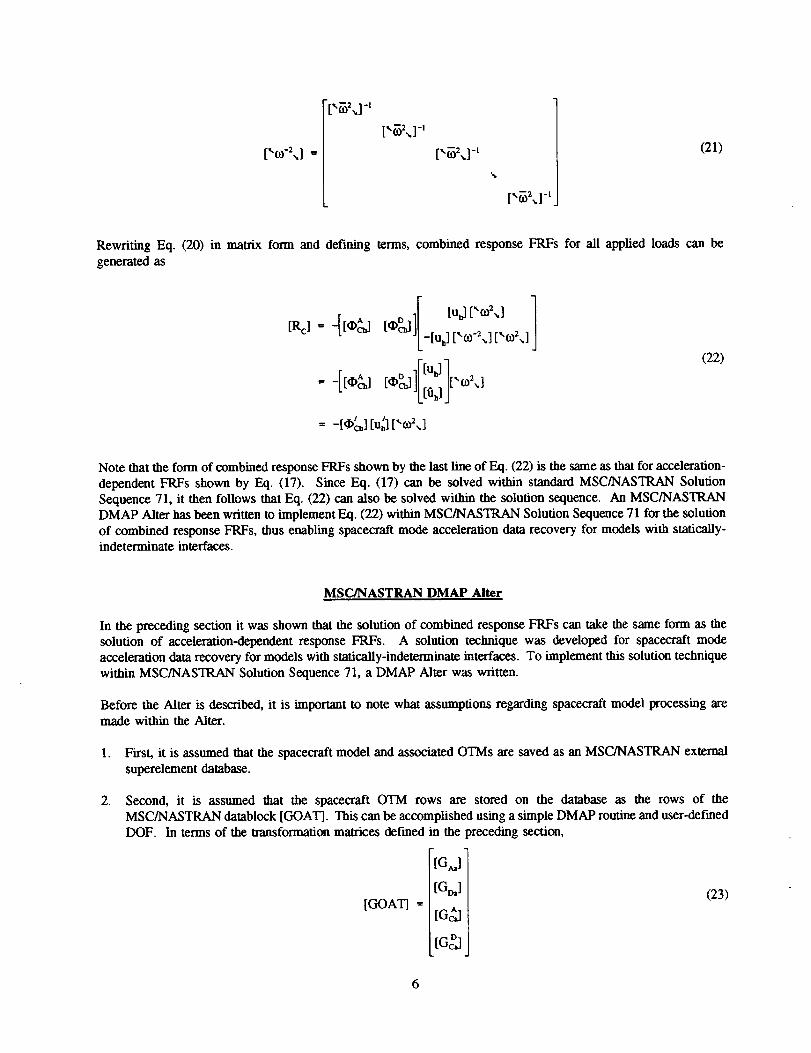
[,_21-.
[,_2.1-, (21)
Rewriting Eq. (20) in matrix form and defining terms, combined response FRFs for all applied loads can begenerated as
[Re] _[[_,] .=DI[ [u_] ["c°2"] ]
-- t*c_ ][_[u: [,m_2 ] [,0_2 ] ]
o .Ftujl, =1(22)
Note that the form of combined response FRFs shown by the last line of Eq. (22) is the same as that for acceleration-dependent FRFs shown by Eq. (17). Since Eq. (17) can be solved within standard MSC/NASTRAN SolutionSequence 71, it then follows that Eq. (22) can also be solved within the solution sequence. An MSC/NASTRANDMAP Alter has been written to implement Eq. (22) within MSC/NASTRAN Solution Sequence 71 for the solutionof combined response FRFs, thus enabling spacecraft mode acceleration data recovery for models with statically-indeterminate interfaces.
MSC/NASTRAN DMAP Alter
In the preceding section it was shown that the solution of combined response FRFs can take the same form as thesolution of acceleration-dependent response FRFs. A solution technique was developed for spacecraft modeacceleration data recovery for models with statically-indeterminate interfaces. To implement this solution techniquewithin MSC/NASTRAN Solution Sequence 71, a DMAP Alter was written.
Before the Alter is described, it is important to note what assumptions regarding spacecraft model processing aremade within the Alter.
.
.
First, it is assumed that the spacecraft model and associated OTMs are saved as an MSC/NASTRAN external
superelement database.
Second, it is assumed that the spacecraft OTM rows are stored on the database as the rows of theMSC/NASTRAN datablock [GOAT]. This can be accomplished using a simple DMAP routine and user-definedDOF. In terms of the transformation matrices defmed in the preceding section,
[Gj
[GD,] (23)
tGOaaq= tG jt
tGg l_ _1
6
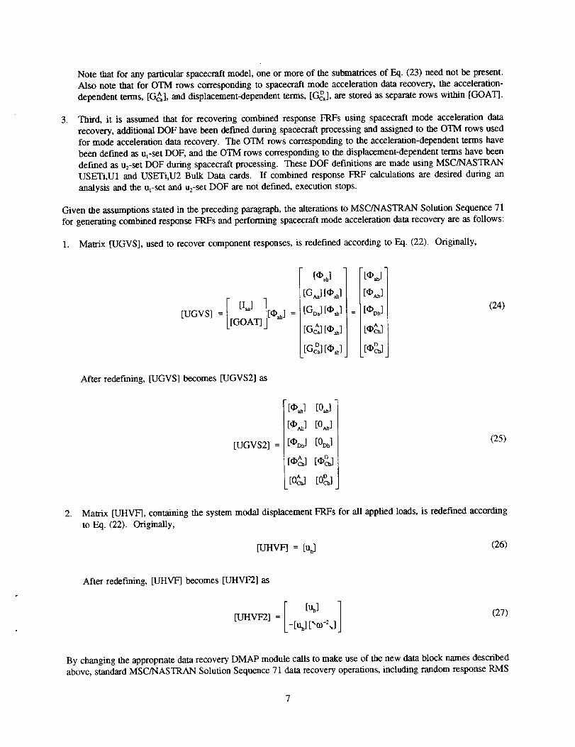
Note that for any particular spacecraft model, one or more of the submatrices of Eq. (23) need not be present.
Also note that for OTM rows corresponding to spacecraft mode acceleration data recovery, the acceleration-
dependent terms, [G_,], and displacement-dependent terms, [GcD_],are stored as separate rows within [GOAT].
. Third, it is assumed that for recovering combined response FRFs using spacecraft mode acceleration data
recovery, additional DOF have been defined during spacecraft processing and assigned to the OTM rows usedfor mode acceleration data recovery. The OTM rows corresponding to the acceleration-dependent terms have
been defined as u_-set DOF, and the OTM rows corresponding to the displacement-dependent terms have been
defined as u2-set DOF during spacecraft processing. These DOF definitions are made using MSC/NASTRANUSETi,U1 and USETi,U2 Bulk Data cards. If combined response FRF calculations are desired during an
analysis and the ul-set and u2-set DOF are not defined, execution stops.
Given the assumptions stated in the preceding paragraph, the alterations to MSC/NASTRAN Solution Sequence 71
for generating combined response FRFs and performing spacecraft mode acceleration data recovery are as follows:
1. Matrix [UGVS], used to recover component responses, is redefined according to Eq. (22). Originally,
[UGVS] =
After redefining, [UGVS] becomes [UGVS2] as
[UGVS2] --
[0_]
[Gj tOj
[Gt>,] [Oj
D
[Gcj [Oj
"[O,_] [0j
[O_] [0j
[O_] [0o_]
[Oj
[,_]
: [OoJ
[,t,_]
(24)
(25)
, Matrix [UHVF], containing the system modal displacement FRFs for all applied loads, is redefined according
to Eq. (22). Originally,
[UHVF] = [uh] (26)
After redefining, [UHVF] becomes [UHVF2] as
[UHVF2] = (27)
By changing the appropriate data recovery DMAP module calls to make use of the new data block names describedabove, standard MSC/NASTRAN Solution Sequence 71 data recovery operations, including random response RMS

calculations, can proceed as usual. In general, response FRFs are calculated as
[R] = [UGVS2] [UHVF2] (28)
To request MSC/NASTRAN XY-OUTPUT data for any of the original rows of the OTMs for which combined
response FRFs are being calculated, the analyst must request acceleration type data recovery for the corresponding
acceleration-dependent (ut-se0 DOF.
Numerical Example
An MSC/NASTRAN Solution Sequence 71 DMAP Alter for performing spacecraft mode acceleration data recoveryfor models with statically-indeterminate interfaces was developed to analyze ELVlspacecraft buffeting wind events.
A typical frequency domain buffeting wind analysis is illustrated in Figure 1. The flee-free ELV/spacecraft systemis assumed to be flying through the atmosphere and subjected to buffeting wind loads. These types of loads typically
build up in areas of differing system geometry. Two such locations are at the intersection of a bulbous Nose Fairingand the core vehicle and at the intersection of Solid Rocket Motors and the core vehicle. These areas are identified
in Figure 1. Due to their random nature, the wind loads are represented as applied load power spectral density
functions. The objective of such analyses is to generate spacecraft response RMS values.
For this numerical example, the ELV/spacecraft system is comprised of seven external superelements and residual
structure bulk data. Approximately 3,200 MSC/NASTRAN g-set DOF are within the residual structure. Eighteen
applied loads, each defined by a power spectral density curve, act on the coupled system perpendicular to the longaxis of the system.
For the example spacecraft, the physical connection between its model and the ELV model is made at six grid points
and corresponds to thirty-six MSC/NASTRAN b-set DOF; hence, it is statieally-indeterminate. To recover spacecraft
loads, mode acceleration method OTMs are used. The spacecraft physical and generalized boundary (a-set) DOF
accelerations and physical boundary (b-se0 DOF displacements are transformed into loads. For the thirty-six
spacecraft interface DOF, interface loads are generated as
{R_(x)} = [Gb,] {a.(x)} + [GbO {ub(x)} (29)
which has the form of the combined responses shown by Eq. (18).
To demonstrate the accuracy of the MSC/NASTRAN Solution Sequence 71 Alter, spacecraft interface load RMS
values were generated using two methods. The fast method involved MSC/NASTRAN and an independently verified
and validated external user-written computer code. MSC/NASTRAN Solution Sequence 71 was used to generate
XY-PUNCH fries containing the applied load power spectral density functions, acceleration-dependent term FRFs,
and displacement-dependent term FRFs. The acceleration- and displacement-dependent term FRFs were combined
within the external code, and the response RMS values were then calculated. The second method involved only
MSC/NASTRAN Solution Sequence 71 and the new Alter to generate the response RMS values.
Spacecraft interface load RMS responses generated using the two methods are listed in Table 1. The first and second
columns are for identifying the spacecraft connection and recovered load, respectively. Listed in the third and fourth
columns are the spacecraft interface load RMS responses generated using MSC/NASTRAN and the external code
and using MSC/NASTRAN with the new Alter, respectively. In column five are listed the spacecraft interface load
RMS response ratios which are equal to the value in column four divided by the value in column three. It is clear
from this numerical example that the MSC/NASTRAN Solution Sequence 71 Alter for performing spacecraft mode
acceleration data recovery for models with statically-indeterminate interfaces executes correctly. It is important to
note that excellent agreement was also achieved when responses internal to the spacecraft were compared.

Summary
An MSC/NASTRAN Solution Sequence 71 DMAP Alter has been written to combine acceleration- and displacement-
dependent modal frequency responses. The new Alter was developed to perform spacecraft mode acceleration datarecovery for models with statically-indeterminate interfaces during modal frequency response analyses. Through thecombined use of DMAP and user-defined sets, combined frequency response functions are automatically generated.
The Alter was written to replace an external user-written computer code used to solve a typical aerospace engineering
problem. It has been shown via a numerical example that the new Alter allows for accurate solutions without theadded user-interfaces and computer resources typically associated with external solution methodologies.
[1]
[21
[3]
[41
References
MSC/NASTRAN Users' Manual, Version 67, Vol. II, The MacNeal-Schwendler Corporation, Los Angeles,
CA, 1991.
Flanigan, C.C., "Efficient and Accurate Procedures for Calculating Data Recovery Matrices," Proc. of the1989 MSC Worm Users' Conference, Los Angeles, CA, 1989.
NASTRAN Theoretical Manual, The MacNeal-Schwendler Corporation, Los Angeles, CA, 1972.
Hildebrand, F.B., Advanced Calculus for Applications, Prentice-Hall, Inc., Englewood Cliffs, NJ, 2nd Ed.,
1976.
Nose Fairing
Solid Rocket Motors
Buffet Loads
Buffet Loads
Figure 1.--ELV/spacecraft system for buffeting wind analysis.

Table1. Results Comparisons for ELV/spacecraft Buffeting Wind Analysis
SpacecraftConnection
2
Recovered
Load
Shear (Ib)
Shear (Ib)
Axial (Ib)
Bend. Morn. (m-lb)
Bend. Mona. (in-lb)
Torque (in-lb)
Shear (lb)
Shear (lb)
Axial 0b)Bend. Morn. (in-lb)
Bend. Mona. (in-lb)
Torque (in-lb)
Shear (lb)
Shear (lb)
Axial (it,)Bend. Mom. (in-lb)
Bend. Morn. (m-lb)
Torque (in-lb)
Shear (lb)Shear (lb)
Axial (lb)
Bend. Mona. (in-lb)
Bend. Mona. (in-lb)
Torque (in-lb)
Shear (lb)
Shear (It))
Axial (lb)
Bend. Morn. (in-lb)
Bend. Morn. (in-lb)
Torque (in-lb)
Shear (lb)
Shear (lb)
Axial (lb)Bend. Morn. (in-lb)
Bend. Mona. (in-lb)
Torque (in-lb)
RMS from
External Code
4.318435E+02
6.076196E+02
1.563176E+03
1.985372E+031.943986E+03
4.726503E+02
4.464110E+026.420402E+02
1.571105E+03
2.125543E+03
1.911408E+03
6.202775E+02
4.349328E+02
6.021744E+02
1.573512E+03
1.892175E+03
1.897608E+03
4.395778E+02
4JM5292E+02
6.100565E+02
1.508558E+03
1.924192E+03
1.834566E+03
4.728231E+02
2.173483E+02
6.608356E+02
1.321302E+03
2.298343E+03
1.519133E+03
2.323901E+02
2.203653E+02
6.055359E+02
1.331196E+03
2.108409E+03
1.551676E+03
2.300419E+02
RMS from
DMAP Alter
4.318439E+02
6.076197E+02
1.563176E+03
1.985372E+03
1.943989E+03
4.726504E+02
4.464114E+02
6.420404E+02
1.571105E+03
2.125543E+03
1.911411E+03
6.202775E+02
4.349332E+02
6.021746E+02
1.573512E+031.892176E+03
1.897611E+03
4.395779E+02
4.045296E+02
6.100567E+02
1.508558E+03
1.924193E+03
1.834568E+034.728232E+02
2.173484E+02
6.608364E+021.321302E+03
2.298345E+03
1.519134E+032.323903E+02
2.203654E+02
6.055367E+02
1.331196E+03
2.108411E+03
1.551676E+03
2.300421E+02
Rado a
1.00
1.00
1.00
1.00
1.00
1.00
1.00
1.00
1.00
1.00
1.001.00
1.00
1.00
1.00
1.00
1.00
1.00
1.00
1.001.00
1.00
1.00
1.00
1.00
1.00
1.00
1.00
1.00
1.00
1.00
1.00
1.00
1.00
1.00
1.00
a - Ratio = (RMS from DMAP Alter) / (RMS from External Code)
10


Form ApprovedREPORT DOCUMENTATION PAGE OMBNo. 0704-0188
Publicreportinghumanforthiscoflectio¢_ol Wormalionis estim=le¢l.to.average1 hou.r perresponse,includingthetimeforrev'.mwing,inst.n.¢lions,searchingexist'ragdatas_J.m_._,,gatheringandmaintainingthe¢lalaneeded,arKIcornlDletingandrevmwlngthe_1.bctionoimlormal_n._ _.commentsregat.oL.ngtn_,ouroefle$11malo orally OIINN"_ OImscollectionOfInlom_ion,includingsuggestionsformclucingthisburden,toWashingtonHeadquatlm'=_S4_tvk:_s,Dr_ectoratpior_lnl.ormal_Oper'd_...s_ _qDo_ 1.gl_bpne_.o_DavisHighway,Suite1204,Arlington,VA 22202-4302,andtotheOfficeofManagementandBuoget.PaperworkReOucllonProlea(0"t04-01U),Wunmgzon,Uc; Zoo.
1. AGENCY USE ONLY (Leave blank) 2. REPORT DATE 3. REPORT TYPE AND DATES COVERED
March 1996
4. TITLE AND SUBTITLE
Combining Acceleration and Displacement Dependent Modal Frequency
Responses Using an MSC/NASTRAN DMAP Alter
6. AUTHOR(S)
Alan R. Barnett, Timothy W. Widrick, and Damian R. Ludwiczak
7. PERFORMING ORGANIZATION NAME(S) AND ADDRESS(ES)
National Aeronautics and Space AdministrationLewis Research Center
Cleveland, Ohio 44135-3191
9. SPONSORING/MONITORING AGENCY NAME(S) AND ADDRESS(ES)
National Aeronautics and Space Administration
Washington, D.C. 20546-0001
Technical Memorandum
5. FUNDING NUMBERS
None
8. PERFORMING ORGANIZATIONREPORT NUMBER
E-10159
10. SPO NSORING/MON R'ORI NGAGENCY REPORT NUMBER
NASA TM- 107188
11. SUPPLEMENTARY NOTES
Prepared for the 1996 World Users' Conference sponsored by The MacNeal-Schwendler Corporation, Los Angeles, California,June 3-7, 1996. Alan R. Barnett and Timothy W. Widrick, Analex Corporation, 3001 Aerospace Parkway, Brook Park, Ohio
44142 (work funded by NASA Contract NAS3-25776); Damian R. Ludwiczak, NASA Lewis Research Center. Responsible
person, Damian R. Ludwiczak, organization code 4310, (216) 433-2383.
12a. DISTRIBUTION/AVAILABILITY STATEMENT
Unclassified- Unlimited
Subject Categories 15 and 39
This publication is available from the NASA Center for Aerospace Informa_on, (301) 621--0390.
12b. DISTRIBUTION CODE
13. ABSTRACT (Maximum 200 words)
Solving for dynamic responsesof free-free launch vehicle/spacecraft systemsacteduponby buffeting winds is com-monly performed throughout the aerospaceindustry. Due to the unpredictablenature of this wind loading event, theseproblems are typically solvedusing frequency responserandom analysistechniques. To generate dynamicresponsesforspacecraft with statically-indeterminate interfaces, spacecraft contractors prefer to develop models which have responsetransformation matrices developed for mode acceleration data recovery. This method transforms spacecraft boundaryaccelerations and displacements into internal responses. Unfortunately, standard MSC/NASTRAN modal frequency
response solution sequences cannot be used to combine acceleration- and displacement-dependent responses required forspacecraft mode acceleration data recovery. External user-written computer codes can be used with MSC/NASTRANoutput to perform such combinations, but these methods can be labor and computer resource intensive. Taking advantageof the analytical and computer resource efficiencies inherent within MSC/NASTRAN, a DMAP Alter has been devel-oped to combine acceleration- and displacement-dependent modal frequency responses for performing spacecraft modeacceleration data recovery. The Alter has been used successfully to efficiently solve a common aerospace buffeting wind
analysis.
14. SUBJECT TERMS
MSC; MSC/NASTRAN; Frequency response; Mode acceleration; DMAP
17. SECURITY CLASSIFICATIONOF REPORT
Unclassified
NSN 7540-01-280-5500
18. SECURITY CLASSIFICATIONOF THIS PAGE
Unclassified
19. SECURITY CLASSIFICATIONOF ABSTRACT
Unclassified
15. NUMBER OF PAGES13
!16. PRICE CODE
A0320. LIMITATION OF ABSTRACT
Standard Form 298 (Rev. 2-89)Prescrl_d by ANSI Sial.Z39-18298-102


"_0
_- _'o_m_..o P"
mm p.w O. 0
0_- -"
_ _,.,_:___c,,,0 •
ozo -"-'m
t.-.3


