Installation Instructions
CompactLogix 5370 L2 ControllersCatalog Numbers 1769-L24ER-QB1B, 1769-L24ER-QBFC1B, 1769-L27ERM-QBFC1B
Prevent Electrostatic Discharge
Before You BeginConsider the following before installing a CompactLogix 5370 L2 controller:
• The control system includes a controller, an embedded power supply, and embedded I/O points.
• The embedded power supply is a 24V DC input, isolated power supply.• You must connect an external Class 2 or SELV-approved power supply
to provide 24V DC power to the system. • The controllers have embedded I/O points. You wire the input and
output points via a removable connector.
• The controller supports the use of Compact I/O modules on the local 1769 CompactBus backplane as local expansion modules.
• You must terminate the end of the CompactBus via a 1769-ECR right end cap.
This equipment is sensitive to electrostatic discharge, which can cause internal damage and affect normal operation. Follow these guidelines when you handle this equipment:
• Touch a grounded object to discharge potential static.• Wear an approved grounding wriststrap.• Do not touch connectors or pins on component boards.• Do not touch circuit components inside the equipment.• Use a static-safe workstation, if available.• Store the equipment in appropriate static-safe packaging when not in use.
2 CompactLogix 5370 L2 Controllers
• You cannot remove nor install Compact I/O modules while the controller is powered.
Install the Secure Digital CardThe CompactLogix 5370 L2 controller is shipped from the factory with the 1784-SD1 SD card installed.
Complete these steps to re-install an SD card that has been removed from the controller back into the controller or if installing a new SD card into the controller.
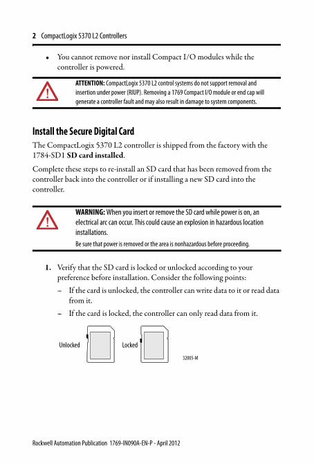
1. Verify that the SD card is locked or unlocked according to your preference before installation. Consider the following points:– If the card is unlocked, the controller can write data to it or read data
from it.– If the card is locked, the controller can only read data from it.
ATTENTION: CompactLogix 5370 L2 control systems do not support removal and insertion under power (RIUP). Removing a 1769 Compact I/O module or end cap will generate a controller fault and may also result in damage to system components.
WARNING: When you insert or remove the SD card while power is on, an electrical arc can occur. This could cause an explosion in hazardous location installations.Be sure that power is removed or the area is nonhazardous before proceeding.
Unlocked Locked
32005-M
Rockwell Automation Publication 1769-IN090A-EN-P - April 2012
CompactLogix 5370 L2 Controllers 3
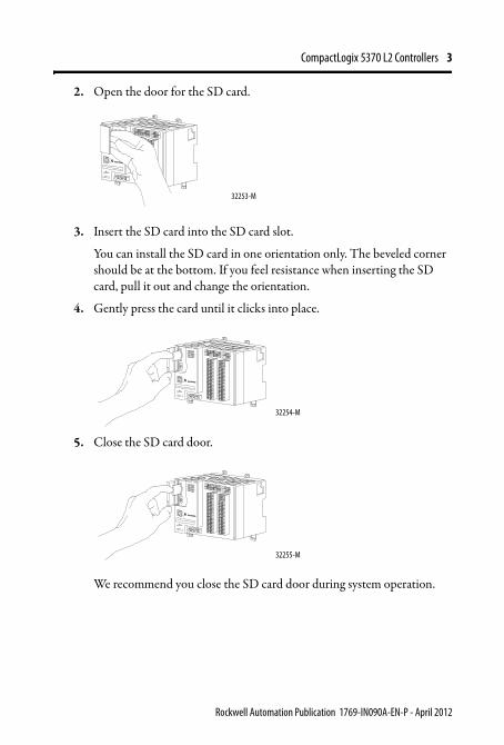
2. Open the door for the SD card.
3. Insert the SD card into the SD card slot.
You can install the SD card in one orientation only. The beveled corner should be at the bottom. If you feel resistance when inserting the SD card, pull it out and change the orientation.
4. Gently press the card until it clicks into place.
5. Close the SD card door.
We recommend you close the SD card door during system operation.
32253-M
32254-M
32255-M
Rockwell Automation Publication 1769-IN090A-EN-P - April 2012
4 CompactLogix 5370 L2 Controllers
Mount the System
Mount a CompactLogix 5370 L2 control system on a DIN rail or a panel.
Available DIN Rails
You can mount the CompactLogix 5370 L2 controller on these DIN rails:
• EN 50 022 - 35 x 7.5 mm (1.38 x 0.30 in.)• EN 50 022 - 35 x 15 mm (1.38 x 0.59 in.)
WARNING: When used in a Class I, Division 2, hazardous location, this equipment must be mounted in a suitable enclosure with proper wiring method that complies with the governing electrical codes.
ATTENTION: This product is grounded through the DIN rail to chassis ground. Use zinc-plated yellow-chromate steel DIN rail to assure proper grounding. The use of other DIN rail materials (for example, aluminum or plastic) that can corrode, oxidize, or are poor conductors, can result in improper or intermittent grounding. Secure DIN rail to mounting surface approximately every 200 mm (7.8 in.) and use end-anchors appropriately.
Rockwell Automation Publication 1769-IN090A-EN-P - April 2012
CompactLogix 5370 L2 Controllers 5
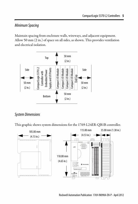
Minimum Spacing
Maintain spacing from enclosure walls, wireways, and adjacent equipment. Allow 50 mm (2 in.) of space on all sides, as shown. This provides ventilation and electrical isolation.
System Dimensions
This graphic shows system dimensions for the 1769-L24ER-QB1B controller.
Bottom
Top
Com
pactL
ogix
5370
L2
Cont
rolle
r with
Em
bedd
ed Po
wer
Supp
ly an
d I/O
Point
s
End C
ap
50 mm
(2 in.)
50 mm
(2 in.)
50 mm
(2 in.)
50 mm
(2 in.)
Side Side
Com
pact
I/O M
odul
eCo
mpa
ct I/O
Mod
ule
Com
pact
I/O M
odul
e
Com
pact
I/O M
odul
e
00:00:BC:2E:69:F6
L24ER0 1 2 3 4 5 6 7
8 9 10 11 12 13 14 15
0 1 2 3 4 5 6 7
8 9 10 11 12 13 14 15
DC
INPU
T
24VD
CSI
NK\
SOU
RCE
24VD
CSO
URC
E
OU
TPU
TD
C
+24VDC COM FG
00
01
02
03
04
05
06
07
NC
+V
00
01
02
03
04
05
06
07
COM0
COM0
08
09
10
11
12
13
14
15
NC
+V
08
09
10
11
12
13
14
15
COM1
COM1
DC IN
DC OUT
QB1B
118.00 mm
(4.65 in.)
115.00 mm
(4.53 in.)
35.00 mm (1.38 in.)105.00 mm
(4.13 in.)
Rockwell Automation Publication 1769-IN090A-EN-P - April 2012
6 CompactLogix 5370 L2 Controllers
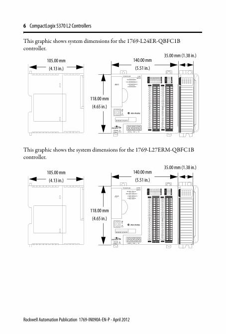
This graphic shows system dimensions for the 1769-L24ER-QBFC1B controller.
This graphic shows the system dimensions for the 1769-L27ERM-QBFC1B controller.
0 1 2 3 4 5 6 7
8 9 10 11 12 13 14 15
0 1 2 3 4 5 6 7
8 9 10
A0 B0 Z0
A1 B1 Z1
0 2 FUSE
1 3 OK11 12 13 14 15
HIG
H S
PEED
COU
NTE
R
INO
UT
DC
INPU
T
24VD
CSI
NK\
SOU
RCE
24VD
CSO
URC
E
OU
TPU
TD
C
+24VDC COM FG
00
01
02
03
04
05
06
07
NC
+V
00
01
02
03
04
05
06
07
COM0
COM0
08
09
10
11
12
13
14
15
NC
+V
08
09
10
11
12
13
14
15
COM1
COM1
A0+
B0+
Z0+
A1+
B1+
Z1+
+V
OUT1
OUT0
COM COM
A0-
B0-
Z0-
A1-
B1-
Z1-
+V
0UT3
Vin0+
Vin2+
VOUT0+I
OUT0+
VOUT1+
Iin3+
Vin1+Iin1+
Iin1+
Vin3+
CJC-
CJC+
V/Iin1-
V/Iin3-
V/Iin0-
V/Iin2-
Iin0+
Iin2+
OUT2
COMCOM
DC IN HSC
DC OUT ANALOG
00:00:BC:2E:69:F6
QBFC1B
105.00 mm
(4.13 in.)
118.00 mm
(4.65 in.)
35.00 mm (1.38 in.)140.00 mm
(5.51 in.)
0 1 2 3 4 5 6 7
8 9 10 11 12 13 14 15
0 1 2 3 4 5 6 7
8 9 10
A0 B0 Z0
A1 B1 Z1
0 2 FUSE
1 3 OK11 12 13 14 15
HIG
H S
PEED
COU
NTE
R
INO
UT
DC
INPU
T
24VD
CSI
NK\
SOU
RCE
24VD
CSO
URC
E
OU
TPU
TD
C
+24VDC COM FG
00
01
02
03
04
05
06
07
NC
+V
00
01
02
03
04
05
06
07
COM0
COM0
08
09
10
11
12
13
14
15
NC
+V
08
09
10
11
12
13
14
15
COM1
COM1
A0+
B0+
Z0+
A1+
B1+
Z1+
+V
OUT1
OUT0
COM COM
A0-
B0-
Z0-
A1-
B1-
Z1-
+V
0UT3
Vin0+
Vin2+
VOUT0+I
OUT0+
VOUT1+
Iin3+
Vin1+Iin1+
Iin1+
Vin3+
CJC-
CJC+
V/Iin1-
V/Iin3-
V/Iin0-
V/Iin2-
Iin0+
Iin2+
OUT2
COMCOM
DC IN HSC
DC OUT ANALOG
00:00:BC:2E:69:F6
L27ERM
QBFC1B
105.00 mm
(4.13 in.)
118.00 mm
(4.65 in.)
35.00 mm (1.38 in.)140.00 mm
(5.51 in.)
Rockwell Automation Publication 1769-IN090A-EN-P - April 2012
CompactLogix 5370 L2 Controllers 7
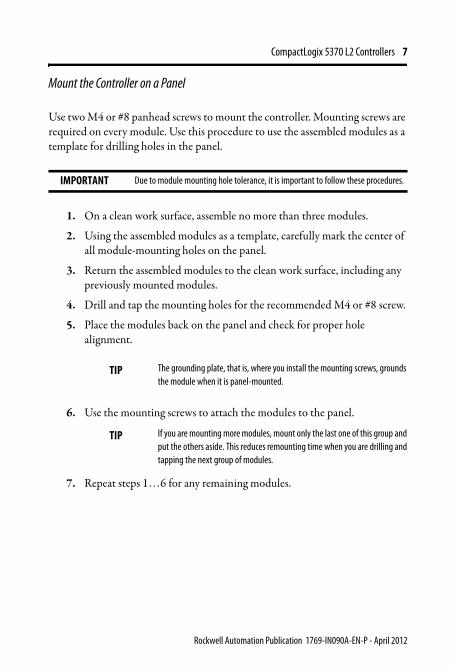
Mount the Controller on a Panel
Use two M4 or #8 panhead screws to mount the controller. Mounting screws are required on every module. Use this procedure to use the assembled modules as a template for drilling holes in the panel.
1. On a clean work surface, assemble no more than three modules.
2. Using the assembled modules as a template, carefully mark the center of all module-mounting holes on the panel.
3. Return the assembled modules to the clean work surface, including any previously mounted modules.
4. Drill and tap the mounting holes for the recommended M4 or #8 screw.
5. Place the modules back on the panel and check for proper hole alignment.
6. Use the mounting screws to attach the modules to the panel.
7. Repeat steps 1…6 for any remaining modules.
IMPORTANT Due to module mounting hole tolerance, it is important to follow these procedures.
TIP The grounding plate, that is, where you install the mounting screws, grounds the module when it is panel-mounted.
TIP If you are mounting more modules, mount only the last one of this group and put the others aside. This reduces remounting time when you are drilling and tapping the next group of modules.
Rockwell Automation Publication 1769-IN090A-EN-P - April 2012
8 CompactLogix 5370 L2 Controllers
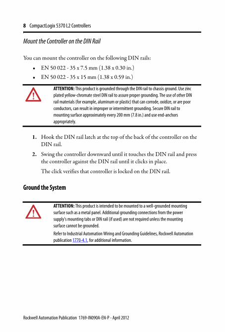
Mount the Controller on the DIN Rail
You can mount the controller on the following DIN rails:
• EN 50 022 - 35 x 7.5 mm (1.38 x 0.30 in.)• EN 50 022 - 35 x 15 mm (1.38 x 0.59 in.)
1. Hook the DIN rail latch at the top of the back of the controller on the DIN rail.
2. Swing the controller downward until it touches the DIN rail and press the controller against the DIN rail until it clicks in place.
The click verifies that controller is locked on the DIN rail.
Ground the System
ATTENTION: This product is grounded through the DIN rail to chassis ground. Use zinc plated yellow-chromate steel DIN rail to assure proper grounding. The use of other DIN rail materials (for example, aluminum or plastic) that can corrode, oxidize, or are poor conductors, can result in improper or intermittent grounding. Secure DIN rail to mounting surface approximately every 200 mm (7.8 in.) and use end-anchors appropriately.
ATTENTION: This product is intended to be mounted to a well-grounded mounting surface such as a metal panel. Additional grounding connections from the power supply's mounting tabs or DIN rail (if used) are not required unless the mounting surface cannot be grounded.
Refer to Industrial Automation Wiring and Grounding Guidelines, Rockwell Automation publication 1770-4.1, for additional information.
Rockwell Automation Publication 1769-IN090A-EN-P - April 2012
CompactLogix 5370 L2 Controllers 9
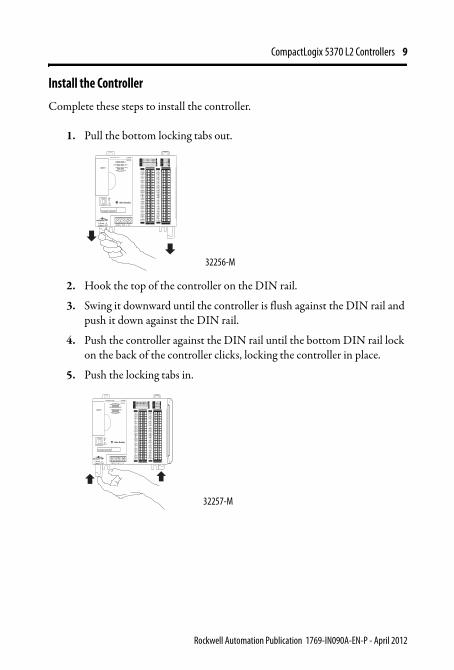
Install the Controller
Complete these steps to install the controller.
1. Pull the bottom locking tabs out.
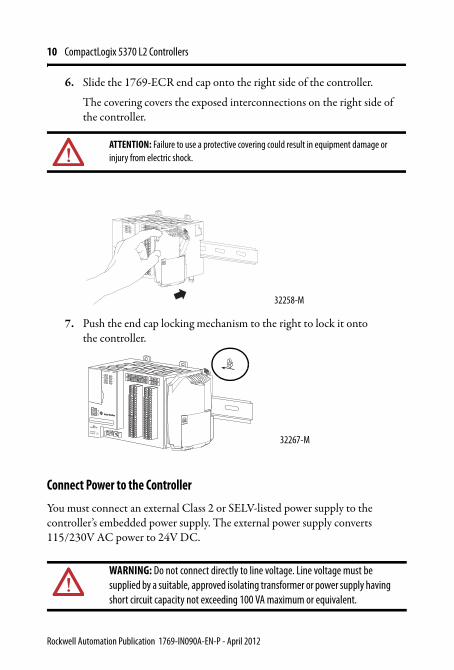
2. Hook the top of the controller on the DIN rail.
3. Swing it downward until the controller is flush against the DIN rail and push it down against the DIN rail.
4. Push the controller against the DIN rail until the bottom DIN rail lock on the back of the controller clicks, locking the controller in place.
5. Push the locking tabs in.
0 1 2 3 4 5 6 7
8 9 10 11 12 13 14 15
0 1 2 3 4 5 6 7
8 9 10
A0 B0 Z0
A1 B1 Z1
0 2 FUSE
1 3 OK11 12 13 14 15
HIG
H S
PEED
COU
NTE
R
INO
UT
DC
INPU
T
24VD
CSI
NK\
SOU
RCE
24VD
CSO
URC
E
OU
TPU
TD
C
+24VDC COM FG
00
01
02
03
04
05
06
07
NC
+V
00
01
02
03
04
05
06
07
COM0
COM0
08
09
10
11
12
13
14
15
NC
+V
08
09
10
11
12
13
14
15
COM1
COM1
A0+
B0+
Z0+
A1+
B1+
Z1+
+V
OUT1
OUT0
COM COM
A0-
B0-
Z0-
A1-
B1-
Z1-
+V
0UT3
Vin0+
Vin2+
VOUT0+I
OUT0+
VOUT1+
Iin3+
Vin1+Iin1+
Iin1+
Vin3+
CJC-
CJC+
V/Iin1-
V/Iin3-
V/Iin0-
V/Iin2-
Iin0+
Iin2+
OUT2
COMCOM
DC IN HSC
DC OUT ANALOG
00:00:BC:2E:69:F6
L27ERM
QBFC1B
32256-M
32257-M
0 1 2 3 4 5 6 7
8 9 10 11 12 13 14 15
0 1 2 3 4 5 6 7
8 9 10
A0 B0 Z0
A1 B1 Z1
0 2 FUSE
1 3 OK11 12 13 14 15
HIG
H S
PEED
COU
NTE
R
INO
UT
DC
INPU
T
24VD
CSI
NK\
SOU
RCE
24VD
CSO
URC
E
OU
TPU
TD
C
+24VDC COM FG
00
01
02
03
04
05
06
07
NC
+V
00
01
02
03
04
05
06
07
COM0
COM0
08
09
10
11
12
13
14
15
NC
+V
08
09
10
11
12
13
14
15
COM1
COM1
A0+
B0+
Z0+
A1+
B1+
Z1+
+V
OUT1
OUT0
COM COM
A0-
B0-
Z0-
A1-
B1-
Z1-
+V
0UT3
Vin0+
Vin2+
VOUT0+I
OUT0+
VOUT1+
Iin3+
Vin1+Iin1+
Iin1+
Vin3+
CJC-
CJC+
V/Iin1-
V/Iin3-
V/Iin0-
V/Iin2-
Iin0+
Iin2+
OUT2
COMCOM
DC IN HSC
DC OUT ANALOG
00:00:BC:2E:69:F6
L27ERM
QBFC1B
Rockwell Automation Publication 1769-IN090A-EN-P - April 2012
10 CompactLogix 5370 L2 Controllers
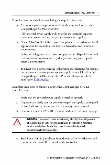
6. Slide the 1769-ECR end cap onto the right side of the controller.
The covering covers the exposed interconnections on the right side of the controller.
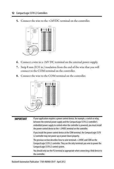
7. Push the end cap locking mechanism to the right to lock it onto the controller.
Connect Power to the Controller
You must connect an external Class 2 or SELV-listed power supply to the controller’s embedded power supply. The external power supply converts 115/230V AC power to 24V DC.
ATTENTION: Failure to use a protective covering could result in equipment damage or injury from electric shock.
WARNING: Do not connect directly to line voltage. Line voltage must be supplied by a suitable, approved isolating transformer or power supply having short circuit capacity not exceeding 100 VA maximum or equivalent.
32258-M
32267-M
Rockwell Automation Publication 1769-IN090A-EN-P - April 2012
CompactLogix 5370 L2 Controllers 11
Consider these points before completing the steps in this section:
• An external power supply must reside in the same enclosure as the CompactLogix 5370 L2 controller.
If the external power supply and controller are located in separate enclosures, an electrical arc can occur when power is applied.
• Not all Class 2 or SELV-listed power supplies are certified for use in all applications, for example, use in both nonhazardous and hazardous environments.
Before installing an external power supply, consult all specification and certification information to verify that you are using an acceptable external power supply.
• You must wire power according to the wiring specifications, for example, the maximum screw torque on a power supply terminal, listed in the CompactLogix 5370 L2 Controllers Product Information Sheet, publication 1769-PC010.
Complete these steps to connect power to the CompactLogix 5370 L2 control system.
1. Verify that the external power supply is installed properly.
2. If appropriate, verify that the power setting on the supply is configured to match the voltage source and that the supply is not powered.
3. Connect a wire to a +24V DC terminal on the external power supply.
4. Strip 8 mm (0.31 in.) insulation from the end of the wire that you will connect to the +24VDC terminal on the controller.
WARNING: If you connect or disconnect wiring while the field-side power is on, an electrical arc can occur. This could cause an explosion in hazardous location installations. Be sure that power is removed or the area is nonhazardous before proceeding.
Rockwell Automation Publication 1769-IN090A-EN-P - April 2012
12 CompactLogix 5370 L2 Controllers
5. Connect the wire to the +24VDC terminal on the controller.
6. Connect a wire to a -24V DC terminal on the external power supply.
7. Strip 8 mm (0.31 in.) insulation from the end of the wire that you will connect to the COM terminal on the controller.
8. Connect the wire to the COM terminal on the controller.
IMPORTANT If your application requires a power control device, for example, a switch or relay, between the external power supply and the CompactLogix 5370 L2 controller’s embedded power supply to control when the controller is powered, you must install the power control device at the +24VDC terminal on the controller.
If you install the power control device at the COM terminal, the CompactLogix 5370 L2 controller may not power up or power down properly.
The previous section describes how to wire terminals +24VDC and COM on the CompactLogix 5370 L2 controller. They are the only terminals you wire to power the CompactLogix 5370 L2 control system.
You should only use the FG terminal as appropriate when connecting a field device to the controller.
0 1 2 3 4 5 6 7
8 9 10 11 12 13 14 15
0 1 2 3 4 5 6 7
8 9 10
A0 B0 Z0
A1 B1 Z1
0 2 FUSE
1 3 OK11 12 13 14 15
HIG
H S
PEED
COU
NTE
R
INO
UT
DC
INPU
T
24VD
CSI
NK\
SOU
RCE
24VD
CSO
URC
E
OU
TPU
TD
C
+24VDC COM FG
0 1 2 3 4 5 6 7
8 9 10 11 12 13 14 15
0 1 2 3 4 5 6 7
8 9 10
A0 B0 Z0
A1 B1 Z1
0 2 FUSE
1 3 OK11 12 13 14 15
HIG
H S
PEED
COU
NTE
R
INO
UT
DC
INPU
T
24VD
CSI
NK\
SOU
RCE
24VD
CSO
URC
E
OU
TPU
TD
C
+24VDC COM FG
00
01
02
03
04
05
06
07
NC
+V
00
01
02
03
04
05
06
07
COM0
COM0
08
09
10
11
12
13
14
15
NC
+V
08
09
10
11
12
13
14
15
COM1
COM1
A0+
B0+
Z0+
A1+
B1+
Z1+
+V
OUT1
OUT0
COM COM
A0-
B0-
Z0-
A1-
B1-
Z1-
+V
0UT3
Vin0+
Vin2+
VOUT0+I
OUT0+
VOUT1+
Iin3+
Vin1+Iin1+
Iin1+
Vin3+
CJC-
CJC+
V/Iin1-
V/Iin3-
V/Iin0-
V/Iin2-
Iin0+
Iin2+
OUT2
COMCOM
DC IN HSC
DC OUT ANALOG
00:00:BC:2E:69:F6
L27ERM
QBFC1B
0 1 2 3 4 5 6 7
8 9 10 11 12 13 14 15
0 1 2 3 4 5 6 7
8 9 10
A0 B0 Z0
A1 B1 Z1
0 2 FUSE
1 3 OK11 12 13 14 15
HIG
H S
PEED
COU
NTE
R
INO
UT
DC
INPU
T
24VD
CSI
NK\
SOU
RCE
24VD
CSO
URC
E
OU
TPU
TD
C
+24VDC COM FG
0 1 2 3 4 5 6 7
8 9 10 11 12 13 14 15
0 1 2 3 4 5 6 7
8 9 10
A0 B0 Z0
A1 B1 Z1
0 2 FUSE
1 3 OK11 12 13 14 15
HIG
H S
PEED
COU
NTE
R
INO
UT
DC
INPU
T
24VD
CSI
NK\
SOU
RCE
24VD
CSO
URC
E
OU
TPU
TD
C
+24VDC COM FG
00
01
02
03
04
05
06
07
NC
+V
00
01
02
03
04
05
06
07
COM0
COM0
08
09
10
11
12
13
14
15
NC
+V
08
09
10
11
12
13
14
15
COM1
COM1
A0+
B0+
Z0+
A1+
B1+
Z1+
+V
OUT1
OUT0
COM COM
A0-
B0-
Z0-
A1-
B1-
Z1-
+V
0UT3
Vin0+
Vin2+
VOUT0+I
OUT0+
VOUT1+
Iin3+
Vin1+Iin1+
Iin1+
Vin3+
CJC-
CJC+
V/Iin1-
V/Iin3-
V/Iin0-
V/Iin2-
Iin0+
Iin2+
OUT2
COMCOM
DC IN HSC
DC OUT ANALOG
00:00:BC:2E:69:F6
L27ERM
QBFC1B
Rockwell Automation Publication 1769-IN090A-EN-P - April 2012
CompactLogix 5370 L2 Controllers 13
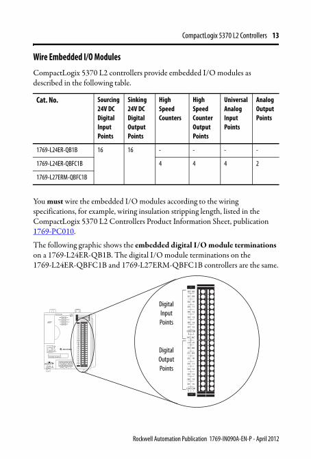
Wire Embedded I/O Modules
CompactLogix 5370 L2 controllers provide embedded I/O modules as described in the following table.
You must wire the embedded I/O modules according to the wiring specifications, for example, wiring insulation stripping length, listed in the CompactLogix 5370 L2 Controllers Product Information Sheet, publication 1769-PC010.
The following graphic shows the embedded digital I/O module terminations on a 1769-L24ER-QB1B. The digital I/O module terminations on the 1769-L24ER-QBFC1B and 1769-L27ERM-QBFC1B controllers are the same.
Cat. No. Sourcing 24V DC Digital Input Points
Sinking 24V DC Digital Output Points
High Speed Counters
High Speed Counter Output Points
Universal Analog Input Points
Analog Output Points
1769-L24ER-QB1B 16 16 - - - -
1769-L24ER-QBFC1B 4 4 4 2
1769-L27ERM-QBFC1B
00:00:BC:2E:69:F6
L24ER0 1 2 3 4 5 6 7
8 9 10 11 12 13 14 15
0 1 2 3 4 5 6 7
8 9 10 11 12 13 14 15
DC
INPU
T
24VD
CSI
NK\
SOU
RCE
24VD
CSO
URC
E
OU
TPU
TD
C
+24VDC COM FG
00
01
02
03
04
05
06
07
NC
+V
00
01
02
03
04
05
06
07
COM0
COM0
08
09
10
11
12
13
14
15
NC
+V
08
09
10
11
12
13
14
15
COM1
COM1
DC IN
DC OUT
00
01
02
03
04
05
06
07
NC
+V
00
01
02
03
04
05
06
07
COM0
COM0
08
09
10
11
12
13
14
15
NC
+V
08
09
10
11
12
13
14
15
COM1
COM1
DC IN
DC OUT
QB1B
Digital Input Points
Digital Output Points
Rockwell Automation Publication 1769-IN090A-EN-P - April 2012
14 CompactLogix 5370 L2 Controllers
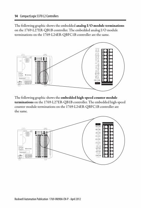
The following graphic shows the embedded analog I/O module terminations on the 1769-L27ER-QB1B controller. The embedded analog I/O module terminations on the 1769-L24ER-QBFC1B controller are the same.
The following graphic shows the embedded high-speed counter module terminations on the 1769-L27ER-QB1B controller. The embedded high-speed counter module terminations on the 1769-L24ER-QBFC1B controller are the same.
0 1 2 3 4 5 6 7
8 9 10 11 12 13 14 15
0 1 2 3 4 5 6 7
8 9 10
A0 B0 Z0
A1 B1 Z1
0 2 FUSE
1 3 OK11 12 13 14 15
HIG
H S
PEED
COU
NTE
R
INO
UT
DC
INPU
T
24VD
CSI
NK\
SOU
RCE
24VD
CSO
URC
E
OU
TPU
TD
C
+24VDC COM FG
00
01
02
03
04
05
06
07
NC
+V
00
01
02
03
04
05
06
07
COM0
COM0
08
09
10
11
12
13
14
15
NC
+V
08
09
10
11
12
13
14
15
COM1
COM1
A0+
B0+
Z0+
A1+
B1+
Z1+
+V
OUT1
OUT0
COM COM
A0-
B0-
Z0-
A1-
B1-
Z1-
+V
0UT3
Vin0+
Vin2+
VOUT0+I
OUT0+
VOUT1+
Iin3+
Vin1+Iin1+
Iin1+
Vin3+
CJC-
CJC+
V/Iin1-
V/Iin3-
V/Iin0-
V/Iin2-
Iin0+
Iin2+
OUT2
COMCOM
DC IN HSC
DC OUT ANALOG
00:00:BC:2E:69:F6
L27ERM
QBFC1B
Vin0+
Vin2+
VOUT0+I
OUT0+
VOUT1+
Iin3+
Vin1+Iin1+
Iin1+
Vin3+
CJC-
CJC+
V/Iin1-
V/Iin3-
V/Iin0-
V/Iin2-
Iin0+
Iin2+
COMCOM
ANALOG
0 1 2 3 4 5 6 7
8 9 10 11 12 13 14 15
0 1 2 3 4 5 6 7
8 9 10
A0 B0 Z0
A1 B1 Z1
0 2 FUSE
1 3 OK11 12 13 14 15
HIG
H S
PEED
COU
NTE
R
INO
UT
DC
INPU
T
24VD
CSI
NK\
SOU
RCE
24VD
CSO
URC
E
OU
TPU
TD
C
+24VDC COM FG
00
01
02
03
04
05
06
07
NC
+V
00
01
02
03
04
05
06
07
COM0
COM0
08
09
10
11
12
13
14
15
NC
+V
08
09
10
11
12
13
14
15
COM1
COM1
A0+
B0+
Z0+
A1+
B1+
Z1+
+V
OUT1
OUT0
COM COM
A0-
B0-
Z0-
A1-
B1-
Z1-
+V
0UT3
Vin0+
Vin2+
VOUT0+I
OUT0+
VOUT1+
Iin3+
Vin1+Iin1+
Iin1+
Vin3+
CJC-
CJC+
V/Iin1-
V/Iin3-
V/Iin0-
V/Iin2-
Iin0+
Iin2+
OUT2
COMCOM
DC IN HSC
DC OUT ANALOG
00:00:BC:2E:69:F6
L27ERM
QBFC1B
A0+
B0+
Z0+
A1+
B1+
Z1+
+V
OUT1
OUT0
COM COM
A0-
B0-
Z0-
A1-
B1-
Z1-
+V
0UT3
OUT2
HSC
Rockwell Automation Publication 1769-IN090A-EN-P - April 2012
CompactLogix 5370 L2 Controllers 15
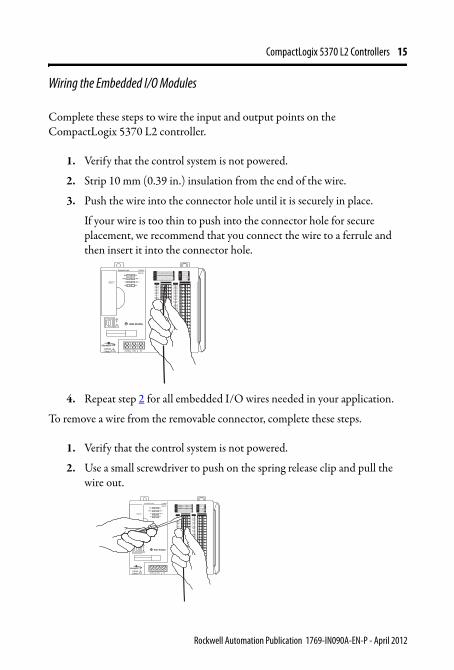
Wiring the Embedded I/O Modules
Complete these steps to wire the input and output points on the CompactLogix 5370 L2 controller.
1. Verify that the control system is not powered.
2. Strip 10 mm (0.39 in.) insulation from the end of the wire.
3. Push the wire into the connector hole until it is securely in place.
If your wire is too thin to push into the connector hole for secure placement, we recommend that you connect the wire to a ferrule and then insert it into the connector hole.
4. Repeat step 2 for all embedded I/O wires needed in your application.
To remove a wire from the removable connector, complete these steps.
1. Verify that the control system is not powered.
2. Use a small screwdriver to push on the spring release clip and pull the wire out.
L27ERM0 1 2 3 4 5 6 7
8 9 10 11 12 13 14 15
0 1 2 3 4 5 6 7
8 9 10
A0 B0 Z0
A1 B1 Z1
0 2 FUSE
1 3 OK11 12 13 14 15
HIG
H S
PEED
COU
NTE
R
INO
UT
DC
INPU
T
24VD
CSI
NK\
SOU
RCE
24VD
CSO
URC
E
OU
TPU
TD
C
+24VDC COM FG
00
01
02
03
04
05
06
07
NC
+V
00
01
02
03
04
05
06
07
COM0
COM0
08
09
10
11
12
13
14
15
NC
+V
08
09
10
11
12
13
14
15
COM1
COM1
A0+
B0+
Z0+
A1+
B1+
Z1+
+V
OUT1
OUT0
COM COM
A0-
B0-
Z0-
A1-
B1-
Z1-
+V
0UT3
Vin0+
Vin2+
VOUT0+I
OUT0+
VOUT1+
Iin3+
Vin1+Iin1+
Iin1+
Vin3+
CJC-
CJC+
V/Iin1-
V/Iin3-
V/Iin0-
V/Iin2-
Iin0+
Iin2+
OUT2
COMCOM
DC IN HSC
DC OUT ANALOG
QBFC1B
Rockwell Automation Publication 1769-IN090A-EN-P - April 2012
Rockwell Automation Support
Rockwell Automation provides technical information on the Web to assist you in using its products. At http://www.rockwellautomation.com/support, you can find technical manuals, technical and application notes, sample code and links to software service packs, and a MySupport feature that you can customize to make the best use of these tools. You can also visit our Knowledgebase at http://www.rockwellautomation.com/knowledgebase for FAQs, technical information, support chat and forums, software updates, and to sign up for product notification updates.For an additional level of technical phone support for installation, configuration, and troubleshooting, we offer TechConnectsm support programs. For more information, contact your local distributor or Rockwell Automation representative, or visit http://www.rockwellautomation.com/support/.
Installation AssistanceIf you experience a problem within the first 24 hours of installation, please review the information that's contained in this manual. You can also contact a special Customer Support number for initial help in getting your product up and running.
New Product Satisfaction ReturnRockwell Automation tests all of its products to ensure that they are fully operational when shipped from the manufacturing facility. However, if your product is not functioning and needs to be returned, follow these procedures.
Documentation Feedback Your comments will help us serve your documentation needs better. If you have any suggestions on how to improve this document, complete this form, publication RA-DU002, available at http://www.rockwellautomation.com/literature/.
United States or Canada 1.440.646.3434
Outside United States or CanadaUse the Worldwide Locator at http://www.rockwellautomation.com/support/americas/phone_en.html, or contact your local Rockwell Automation representative.
United States Contact your distributor. You must provide a Customer Support case number (call the phone number above to obtain one) to your distributor to complete the return process.
Outside United States Please contact your local Rockwell Automation representative for the return procedure.
Publication 1769-IN090A-EN-P - April 2012 PN-147159
Allen-Bradley, CompactLogix, Compact I/O, CompactBus, Rockwell Software, Rockwell Automation, and TechConnect are trademarks of Rockwell Automation, Inc.
Trademarks not belonging to Rockwell Automation are property of their respective companies.
Rockwell Otomasyon Ticaret A.Ş., Kar Plaza İş Merkezi E Blok Kat:6 34752 İçerenköy, İstanbul, Tel: +90 (216) 5698400
Copyright © 2012 Rockwell Automation, Inc. All rights reserved. Printed in the U.S.A.


