Control Systems
Lect. 5 Lead-Lag ControlBasil Hamed
Control Systems
Basil Hamed 2
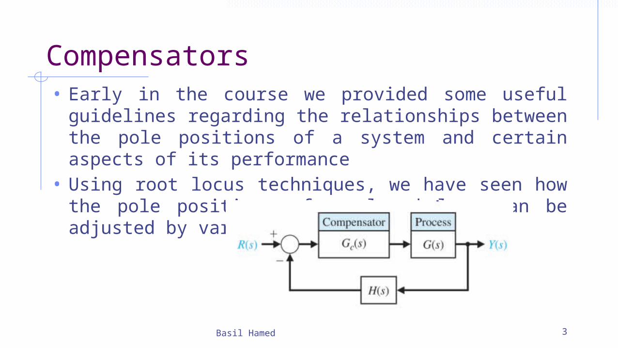
Compensators• Early in the course we provided some useful guidelines
regarding the relationships between the pole positions of a system and certain aspects of its performance
• Using root locus techniques, we have seen how the pole positions of a closed loop can be adjusted by varying a parameter
Basil Hamed 3
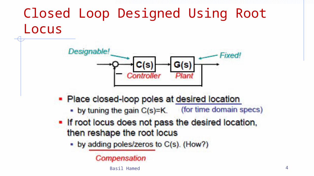
Closed Loop Designed Using Root Locus
Basil Hamed 4
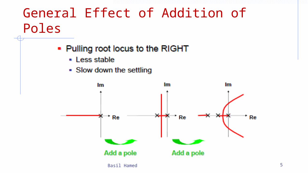
General Effect of Addition of Poles
Basil Hamed 5
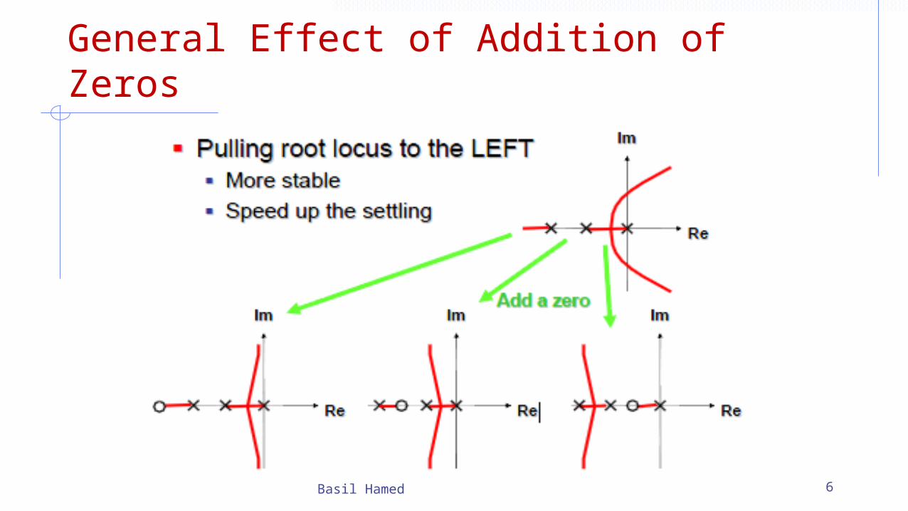
General Effect of Addition of Zeros
Basil Hamed 6
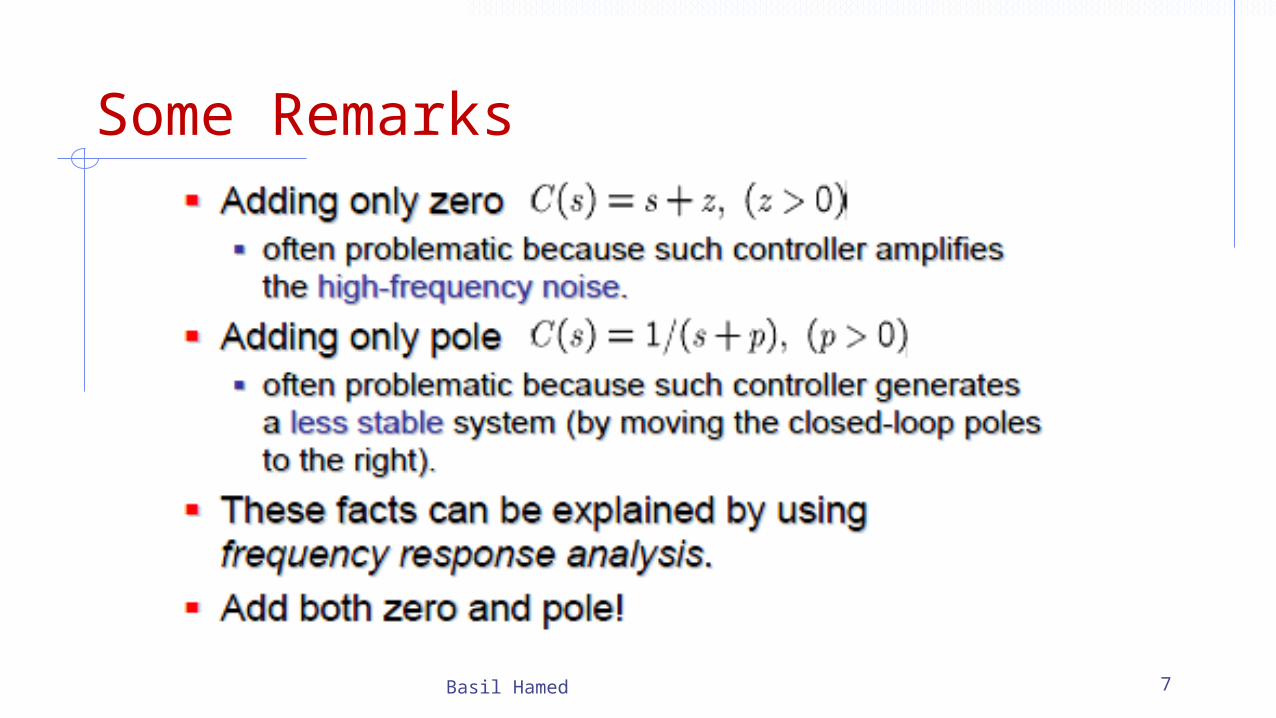
Some Remarks
Basil Hamed 7
8
Lead/Lag Compensation
• Lead/Lag compensation is very similar to PD/PI, or PID control.
• The lead compensator plays the same role as the PD controller, reshaping the root locus to improve the transient response.
• Lag and PI compensation are similar and have the same response: to improve the steady state accuracy of the closed-loop system.
• Both PID and lead/lag compensation can be used successfully, and can be combined.
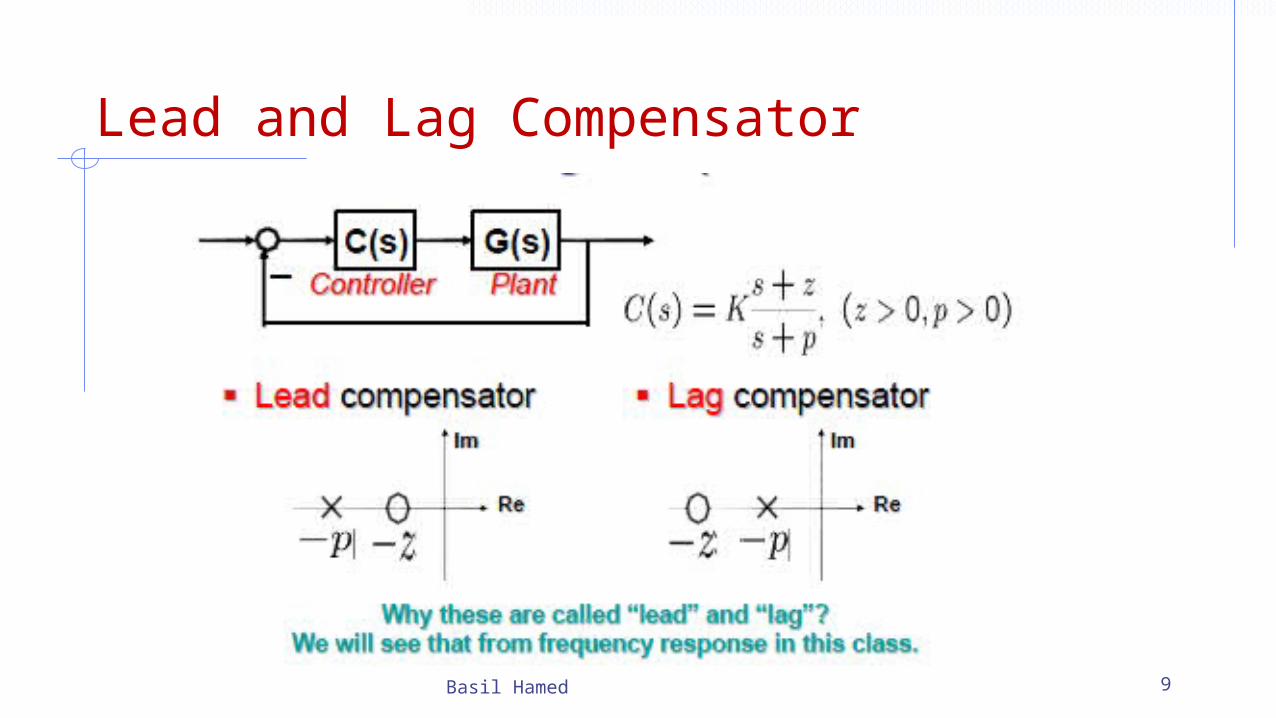
Lead and Lag Compensator
Basil Hamed 9
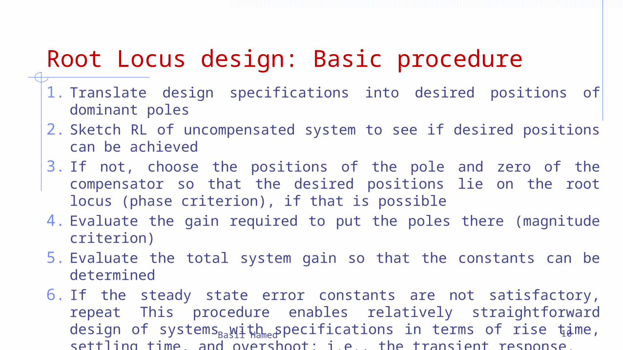
Root Locus design: Basic procedure1. Translate design specifications into desired positions of dominant poles2. Sketch RL of uncompensated system to see if desired positions can be
achieved3. If not, choose the positions of the pole and zero of the compensator so
that the desired positions lie on the root locus (phase criterion), if that is possible
4. Evaluate the gain required to put the poles there (magnitude criterion)5. Evaluate the total system gain so that the constants can be determined6. If the steady state error constants are not satisfactory, repeat This
procedure enables relatively straightforward design of systems with specifications in terms of rise time, settling time, and overshoot; i.e., the transient response.
For systems with steady-state error specifications, Bode (and Nyquist) methods may be more straightforwardBasil Hamed 10
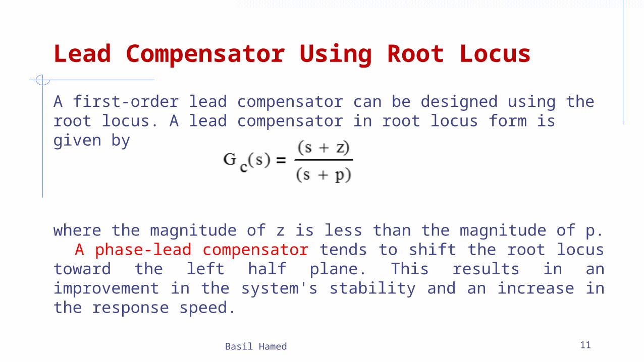
Lead Compensator Using Root Locus
A first-order lead compensator can be designed using the root locus. A lead compensator in root locus form is given by
where the magnitude of z is less than the magnitude of p. A phase-lead compensator tends to shift the root locus toward the left half plane. This results in an improvement in the system's stability and an increase in the response speed.
Basil Hamed 11
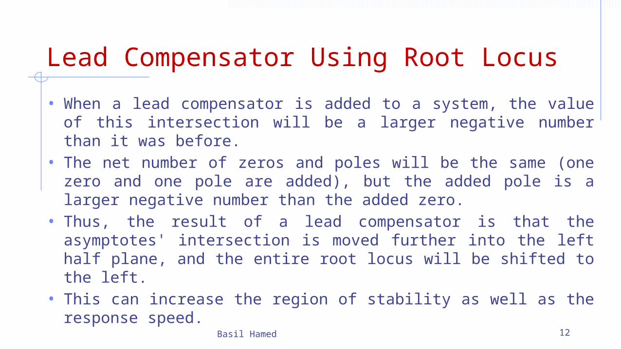
Lead Compensator Using Root Locus
• When a lead compensator is added to a system, the value of this intersection will be a larger negative number than it was before.
• The net number of zeros and poles will be the same (one zero and one pole are added), but the added pole is a larger negative number than the added zero.
• Thus, the result of a lead compensator is that the asymptotes' intersection is moved further into the left half plane, and the entire root locus will be shifted to the left.
• This can increase the region of stability as well as the response speed.
Basil Hamed 12
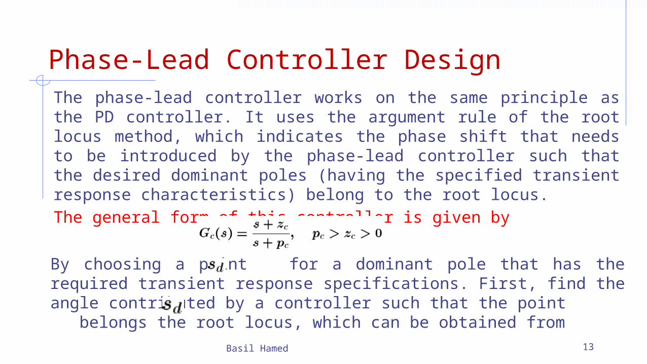
Phase-Lead Controller DesignThe phase-lead controller works on the same principle as the PD controller. It uses the argument rule of the root locus method, which indicates the phase shift that needs to be introduced by the phase-lead controller such that the desired dominant poles (having the specified transient response characteristics) belong to the root locus.The general form of this controller is given by
Basil Hamed 13
By choosing a point for a dominant pole that has the required transient response specifications. First, find the angle contributed by a controller such that the point belongs the root locus, which can be obtained from
Phase-Lead Controller Design
Basil Hamed 14
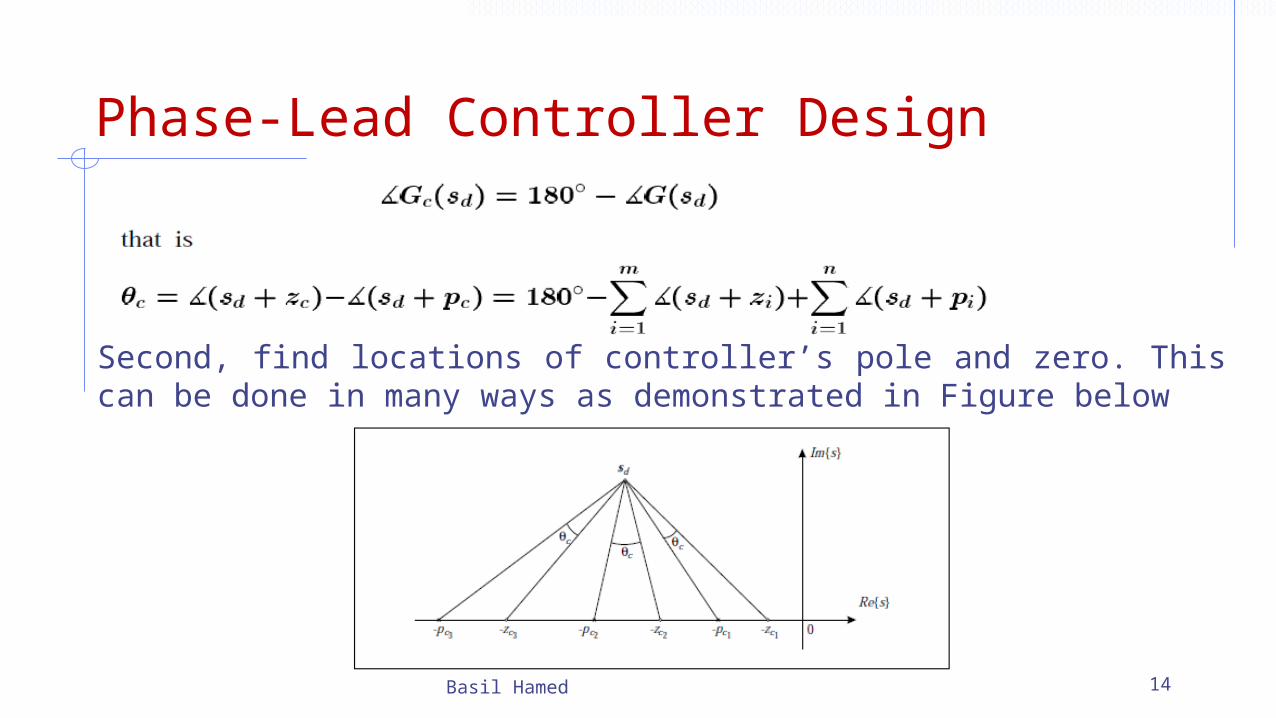
Second, find locations of controller’s pole and zero. This can be done in many ways as demonstrated in Figure below
Phase-Lead Controller Design• All these controllers introduce the same phase shift and have the
same impact on the transient response. However, the impact on the steady state errors is different since it depends on the ratio f . Since this ratio for a phase lead controller is less than one, we conclude that the corresponding steady state constant is reduced and the steady state error is increased.
• Note that if the location of a phase-lead controller zero is chosen, then simple geometry can be used to find the location of the controller’s pole. For example, let be the required zero, then using Figure above the pole
is obtained using:
An algorithm for the phase-lead controller design can be formulated as follows
Basil Hamed 15
Phase-Lead Controller DesignDesign Algorithm:1. Choose a pair of complex conjugate poles in the complex plane
that produces the desired transient response (damping ratio and natural frequency).
2. Find the required phase contribution of a phase-lead controller by using the corresponding formula.
3. Choose values for the controller’s pole and zero by placing them arbitrarily such that the controller will not damage the response dominance of a pair of complex conjugate poles. Some authors (e.g. Van de Verte, 1994) suggest placing the controller zero at
4. Find the controller’s pole by using the corresponding formula.5. Check that the compensated system has a pair of dominant
complex conjugate closed-loop poles.Basil Hamed 16
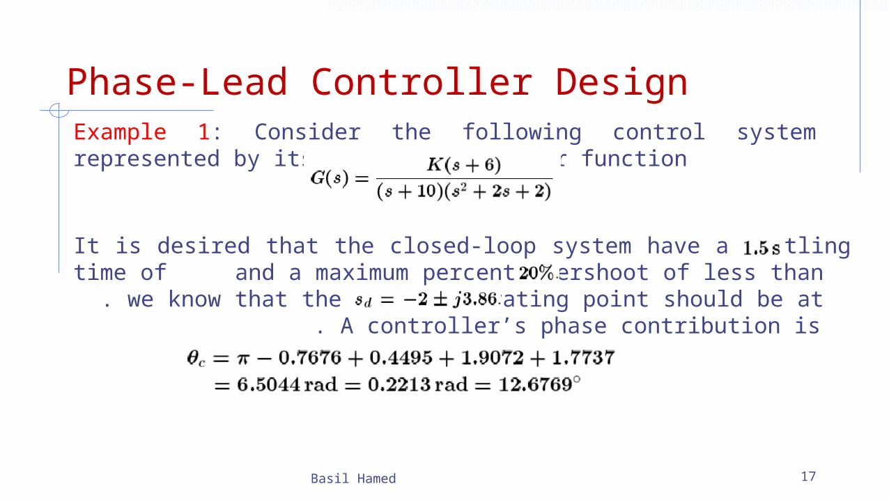
Phase-Lead Controller DesignExample 1: Consider the following control system represented by its open-loop transfer function
Basil Hamed 17
It is desired that the closed-loop system have a settling time of and a maximum percent overshoot of less than . we know that the system operating point should be at . A controller’s phase contribution is
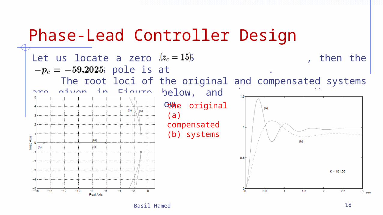
Phase-Lead Controller DesignLet us locate a zero at -15 , then the compensator’s pole is at . The root loci of the original and compensated systems are given in Figure below, and the corresponding step responses in Figure below.
Basil Hamed 18
the original (a) compensated (b) systems
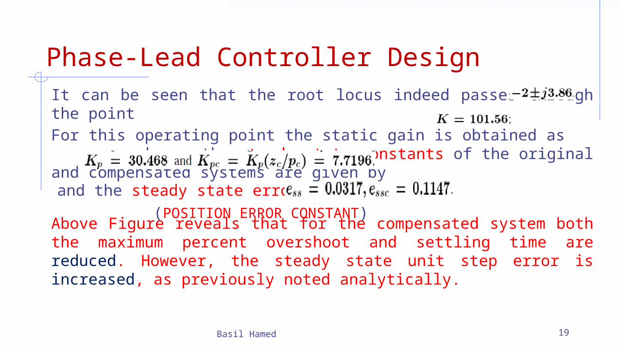
Phase-Lead Controller DesignIt can be seen that the root locus indeed passes through the point For this operating point the static gain is obtained as ; hence the steady state constants of the original and compensated systems are given by (POSITION ERROR CONSTANT)
Basil Hamed 19
and the steady state errors are
Above Figure reveals that for the compensated system both the maximum percent overshoot and settling time are reduced. However, the steady state unit step error is increased, as previously noted analytically.
Phase-Lead Controller Design
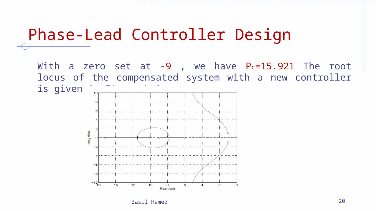
With a zero set at -9 , we have Pc=15.921 The root locus of the compensated system with a new controller is given in Figure below.
Basil Hamed 20

Phase-Lead Controller Design
Basil Hamed 21
It can be seen that this controller also reduces both the overshoot and settling time, while the steady state error is slightly increased.
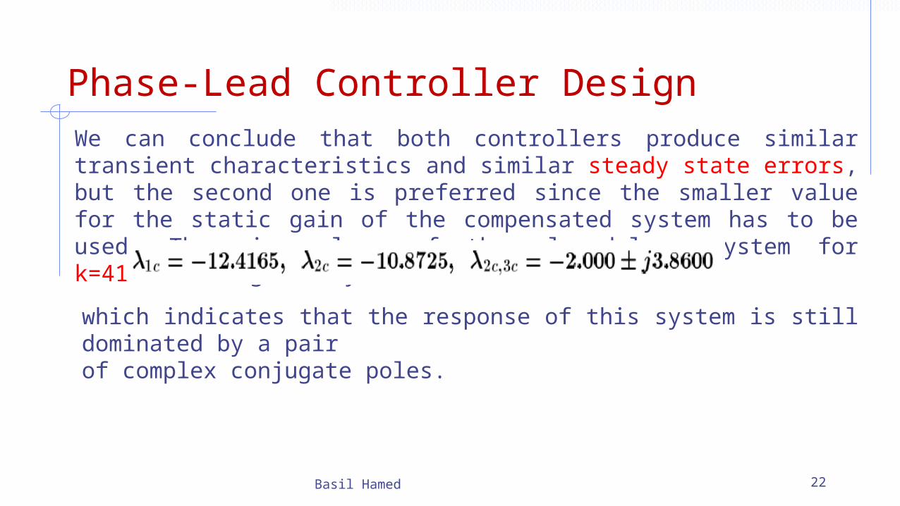
Phase-Lead Controller DesignWe can conclude that both controllers produce similar transient characteristics and similar steady state errors, but the second one is preferred since the smaller value for the static gain of the compensated system has to be used. The eigenvalues of the closed-loop system for k=41.587 are given by
Basil Hamed 22
which indicates that the response of this system is still dominated by a pairof complex conjugate poles.
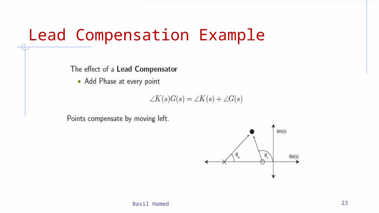
Lead Compensation Example
Basil Hamed 23

Lead Comp. Example 2
Basil Hamed 24
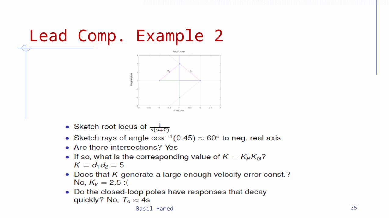
Lead Comp. Example 2
Basil Hamed 25

Lead Comp. Example 3
Basil Hamed 26
Prop. control, step response

Lead Comp. Example 2
Basil Hamed 27
Lead compensated design
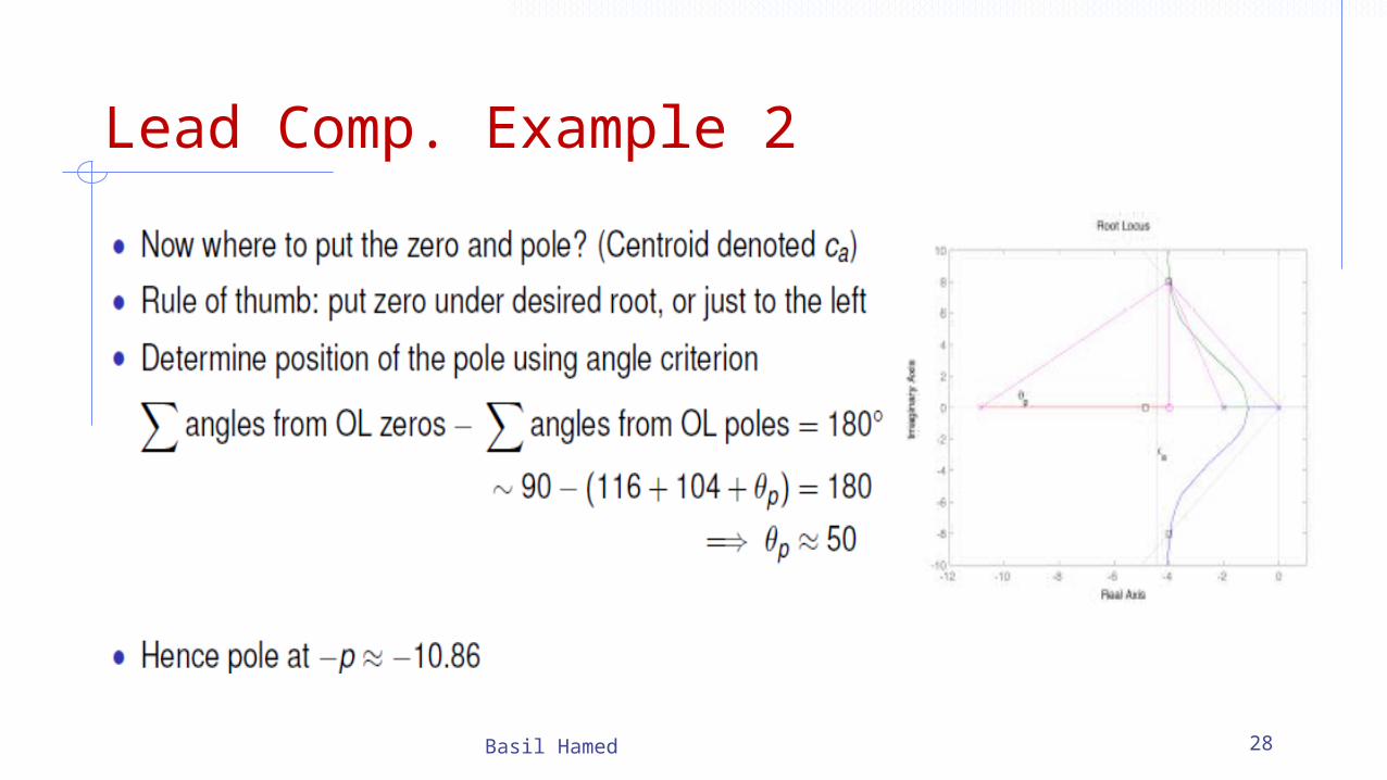
Lead Comp. Example 2
Basil Hamed 28
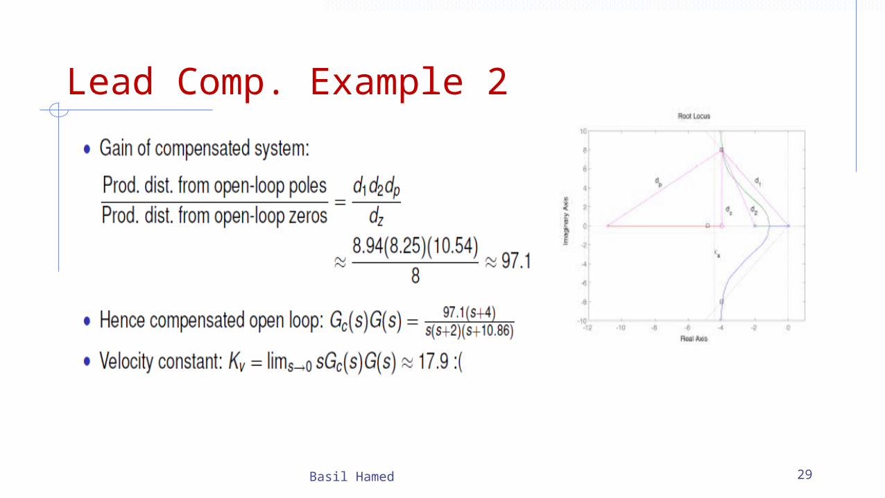
Lead Comp. Example 2
Basil Hamed 29
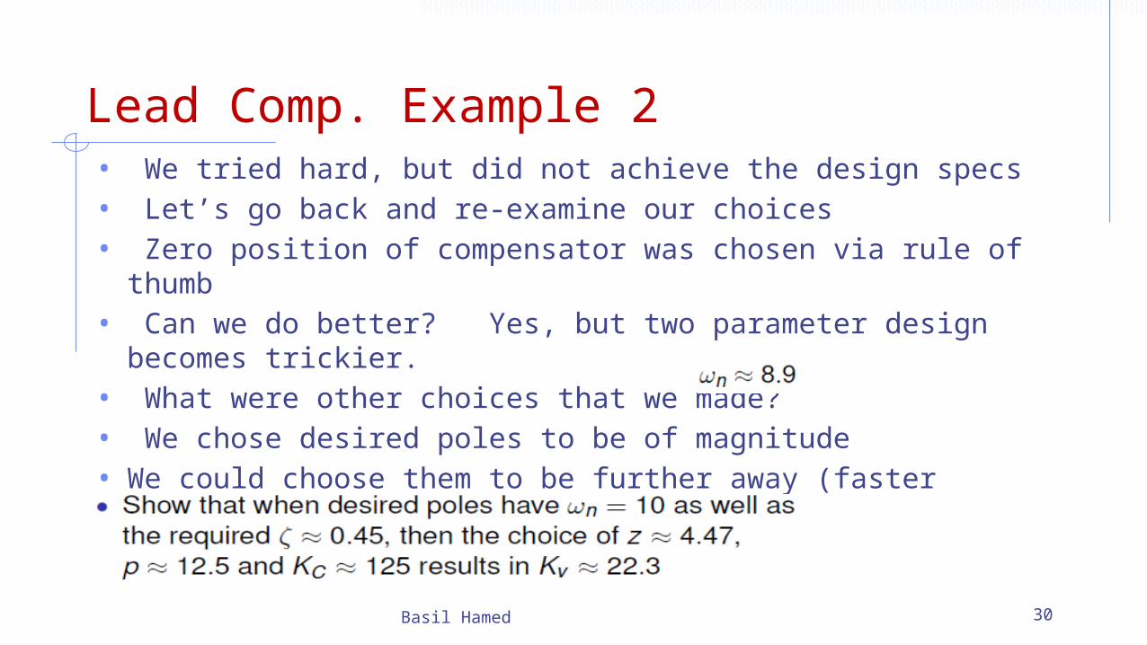
Lead Comp. Example 2• We tried hard, but did not achieve the design specs• Let’s go back and re-examine our choices• Zero position of compensator was chosen via rule of thumb• Can we do better? Yes, but two parameter design becomes
trickier.• What were other choices that we made?• We chose desired poles to be of magnitude • We could choose them to be further away (faster transient
response)• By how much?
Basil Hamed 30
Lead Comp. Example 2
Basil Hamed 31
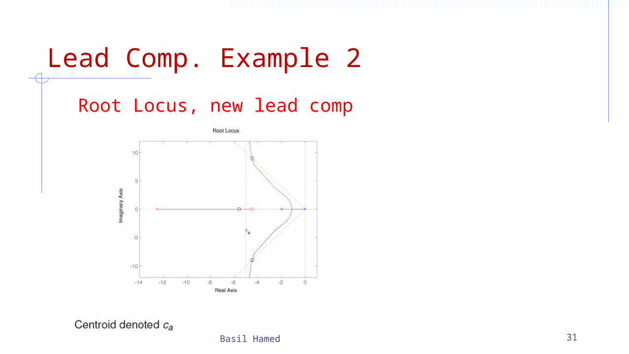
Root Locus, new lead comp

Lead Comp. Example 2
Basil Hamed 32
• Complex conjugate poles still dominate• Closed-loop zero at -4.47 (which is also an open-loop zero)
reduces impact of closed-loop pole at -5.59
New lead comp.

Lead Comp. Example 2
Basil Hamed 33
Note faster settling time than prop. controlled loop, However, the CL zero has increased the overshoot a littlePerhaps we should go back and re-design for in order to better control the overshoot
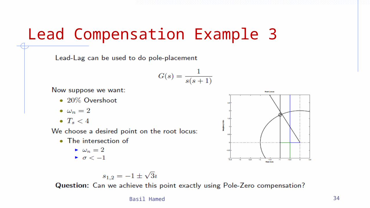
Lead Compensation Example 3
Basil Hamed 34
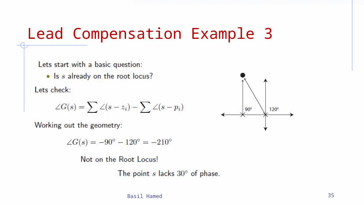
Lead Compensation Example 3
Basil Hamed 35
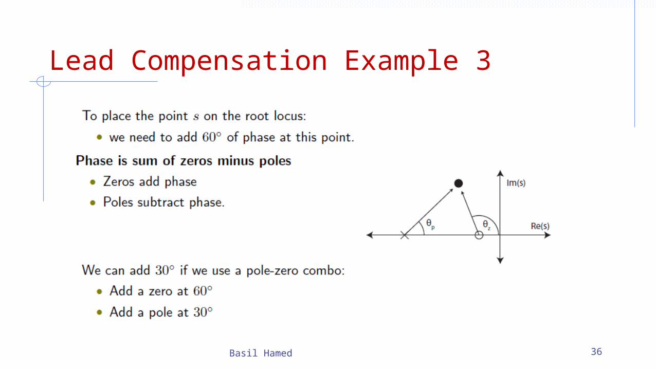
Lead Compensation Example 3
Basil Hamed 36
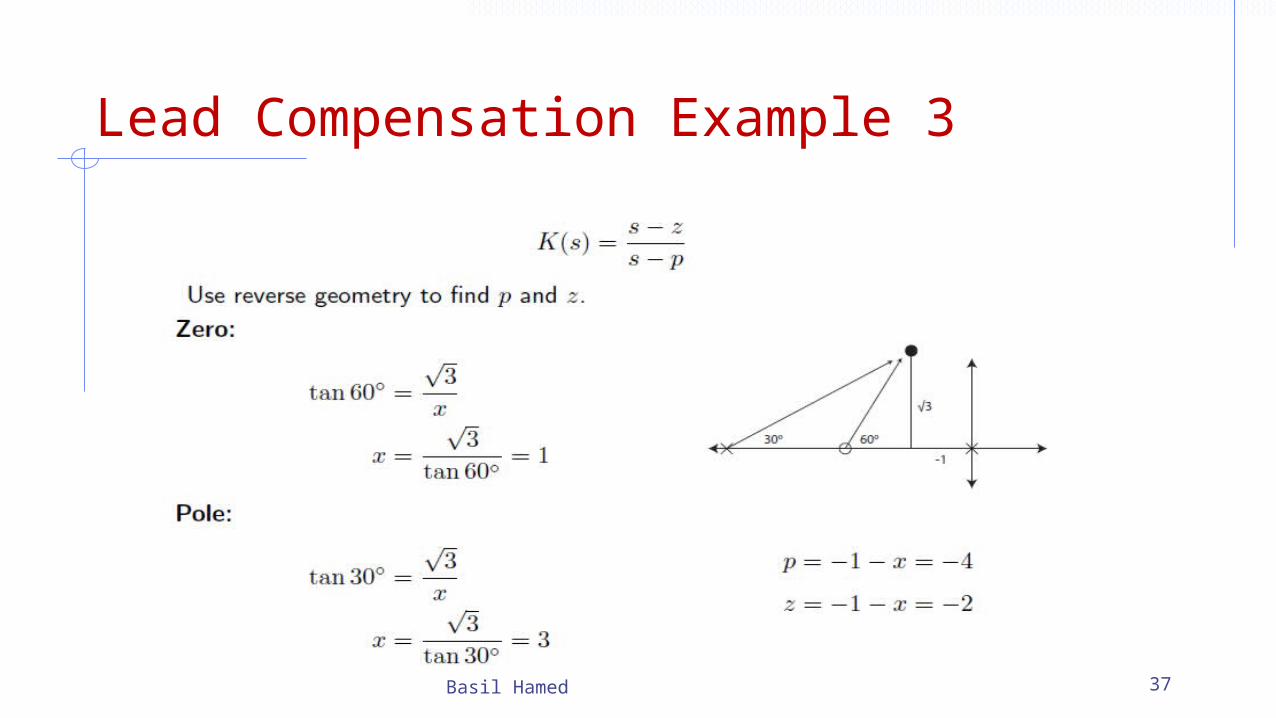
Lead Compensation Example 3
Basil Hamed 37
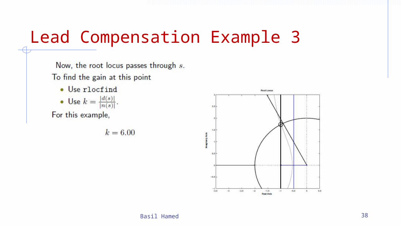
Lead Compensation Example 3
Basil Hamed 38
Lead Compensator Using Root Locus
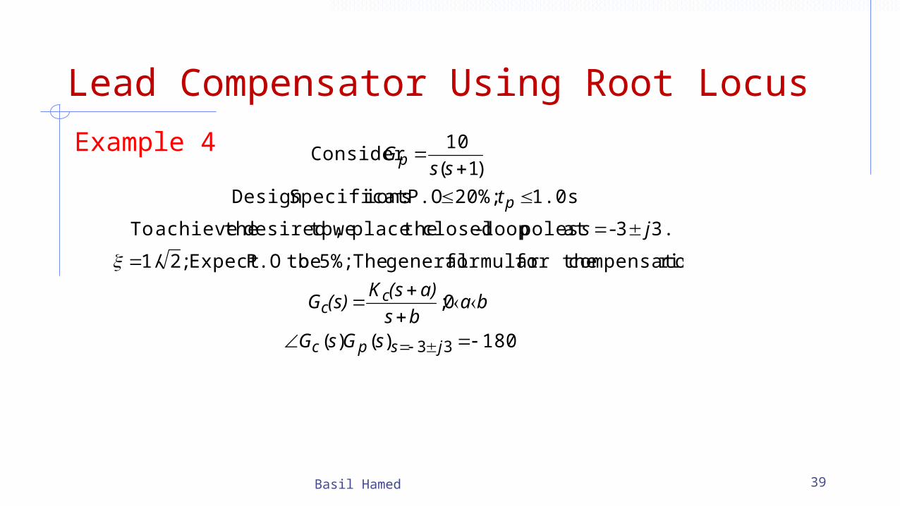
Example 4
Basil Hamed 39
180)()(
0;
isr compensato for theformular general The 5%; be toP.OExpect ;21/
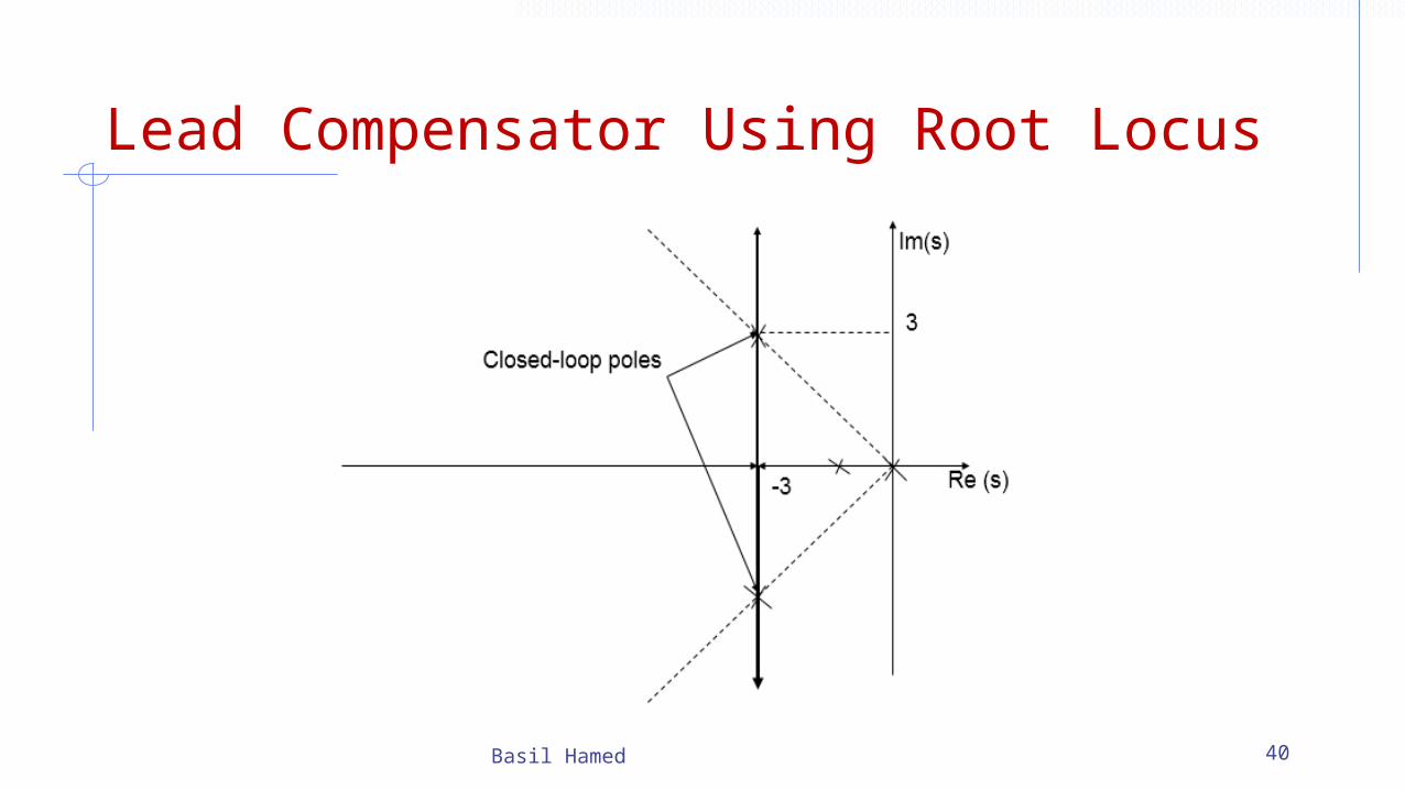
3.3- at poles loop-closed theplace we tp,desired theachieve To
1.0s 20%; P.O :ionsSpecificatDesign
)1(
10Consider
33
jspc
cc
p
p
sGsG
babs
a)(sK(s)G
js
t
ssG
Lead Compensator Using Root Locus
Basil Hamed 40
Lead Compensator Using Root Locus
Basil Hamed 41
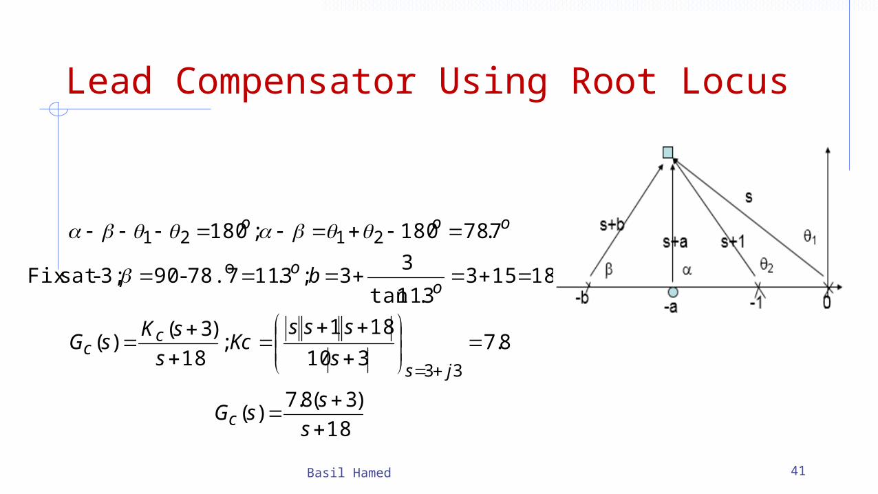
18
)3(8.7)(
8.7310
181;
18
)3()(
181533.11tan
33;3.1178.7-903;-at sFix
7.78180;180
33
o
2121
s
ssG
s
sssKc
s
sKsG
b
c
js
cc
oo
ooo
Lead Compensator Using Root Locus
Basil Hamed 42

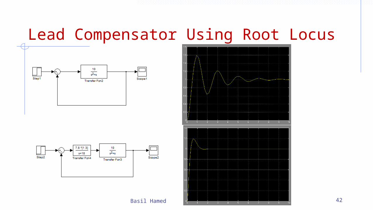
Lead Compensator Using Root Locus• RL approach to phase lead design was reasonably successful in
terms of putting dominant poles in desired positions; e.g., in terms of ζ and ωn
• We did this by positioning the pole and zero of the lead compensator so as to change the shape of the root locus
• However, RL approach does not provide independent control over steady-state error constants (details upcoming)
• That said, since lead compensators reduce the DC gain (they resemble differentiators), they are not normally used to control steady-state error.
• The goal of our lag compensator design will be to increase the steady-state error constants, without moving the other poles too far Basil Hamed 43

Lag Compensator Using Root Locus
A first-order lag compensator can be designed using the root locus. A lag compensator in root locus form is given by
where the magnitude of z is greater than the magnitude of p. A phase-lag compensator tends to shift the root locus to the right, which is undesirable. For this reason, the pole and zero of a lag compensator must be placed close together (usually near the origin) so they do not appreciably change the transient response or stability characteristics of the system.
Basil Hamed 44

Phase-Lag Controller• The phase-lag controller belongs to the same class as the PI controller. • The phase-lag controller can be regarded as a generalization of the PI
controller.• It introduces a negative phase into the feedback loop, which justifies its
name.• It has a zero and pole with the pole being closer to the imaginary axis,
that is
Basil Hamed 45
• The phase-lag controller is used to improve steady state errors.

Lag Compensator Using Root LocusDesign Algorithm :1. Choose a point that has the desired transient specifications on the root locus branch with dominant system poles. Read from the root locus the valuefor the static gain K at the chosen point, and determine the corresponding steady state errors.2. Set both the phase-lag controller’s pole and zero near the origin with theratio obtained such that the desired steady state error requirement is satisfied.3. In the case of controller, adjust for the static loop gain, i.e. take a new static gain as
Basil Hamed 46

Example 5 : Consider the following open-loop transfer function
Let the choice of the static gain k=10 produce a pair of dominant poles on the root locus, which guarantees the desired transient specifications. The corresponding position constant and the steady state unit step error are given by
Basil Hamed 47
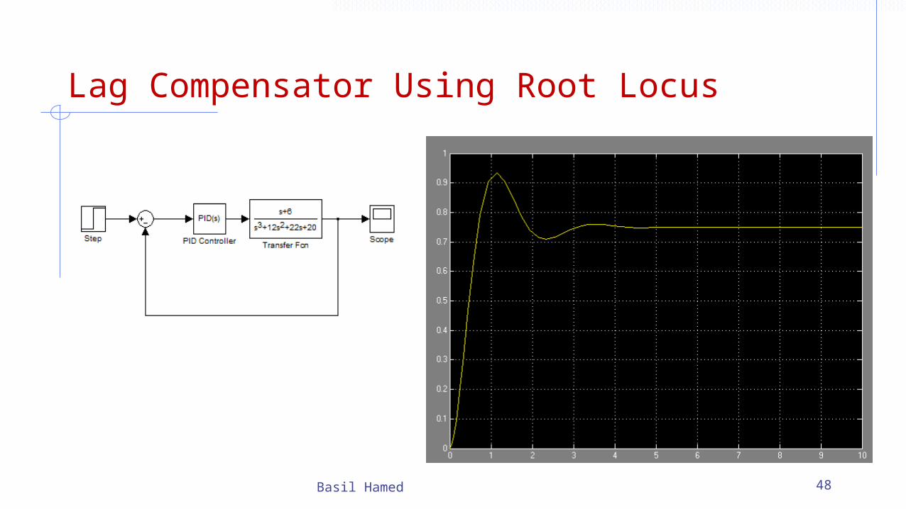
Lag Compensator Using Root Locus
Basil Hamed 48
Lag Compensator Using Root Locus
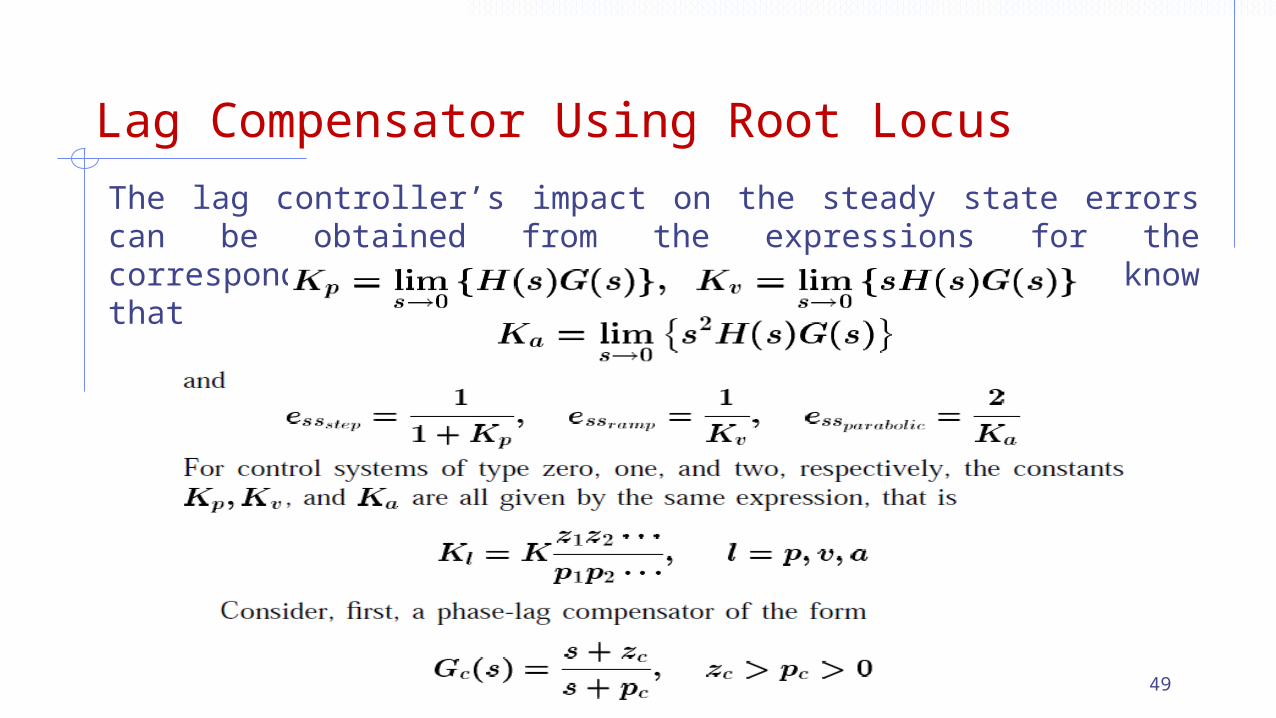
The lag controller’s impact on the steady state errors can be obtained from the expressions for the corresponding steady state constants. Namely, we know that
Basil Hamed 49
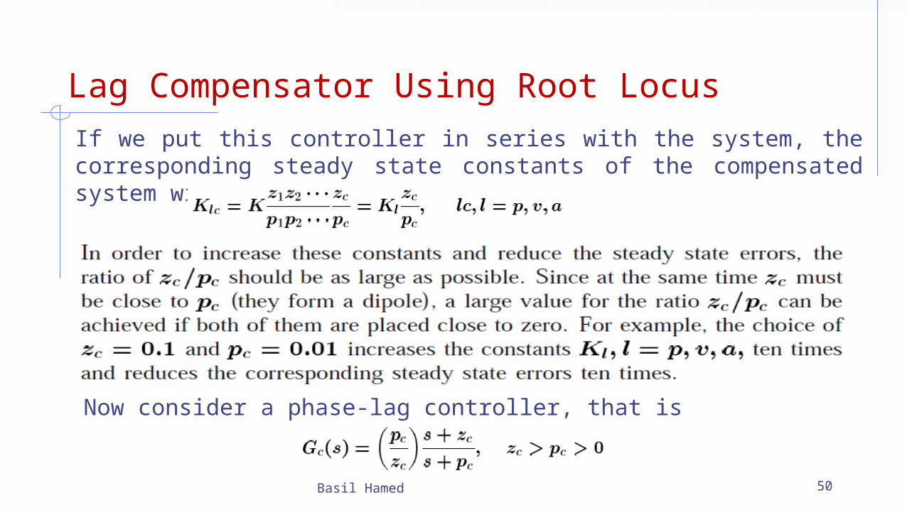
Lag Compensator Using Root LocusIf we put this controller in series with the system, the corresponding steady state constants of the compensated system will be given by
Basil Hamed 50
Now consider a phase-lag controller, that is
Lag Compensator Using Root Locus
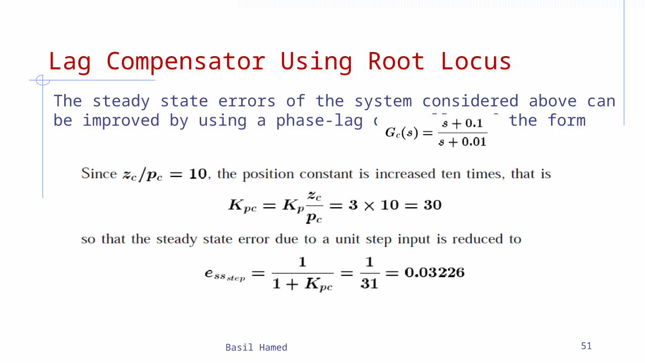
The steady state errors of the system considered above can be improved by using a phase-lag controller of the form
Basil Hamed 51
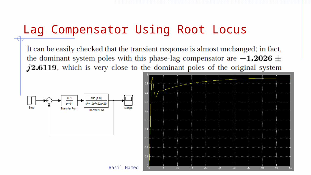
Lag Compensator Using Root Locus
Basil Hamed 52
Lag Compensator Using Root Locus
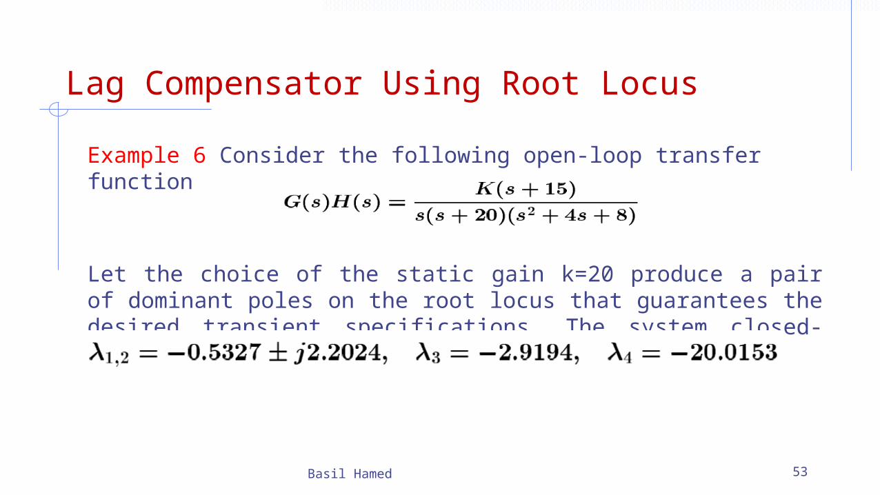
Example 6 Consider the following open-loop transfer function
Let the choice of the static gain k=20 produce a pair of dominant poles on the root locus that guarantees the desired transient specifications. The system closed-loop poles for k=20 are given by
Basil Hamed 53
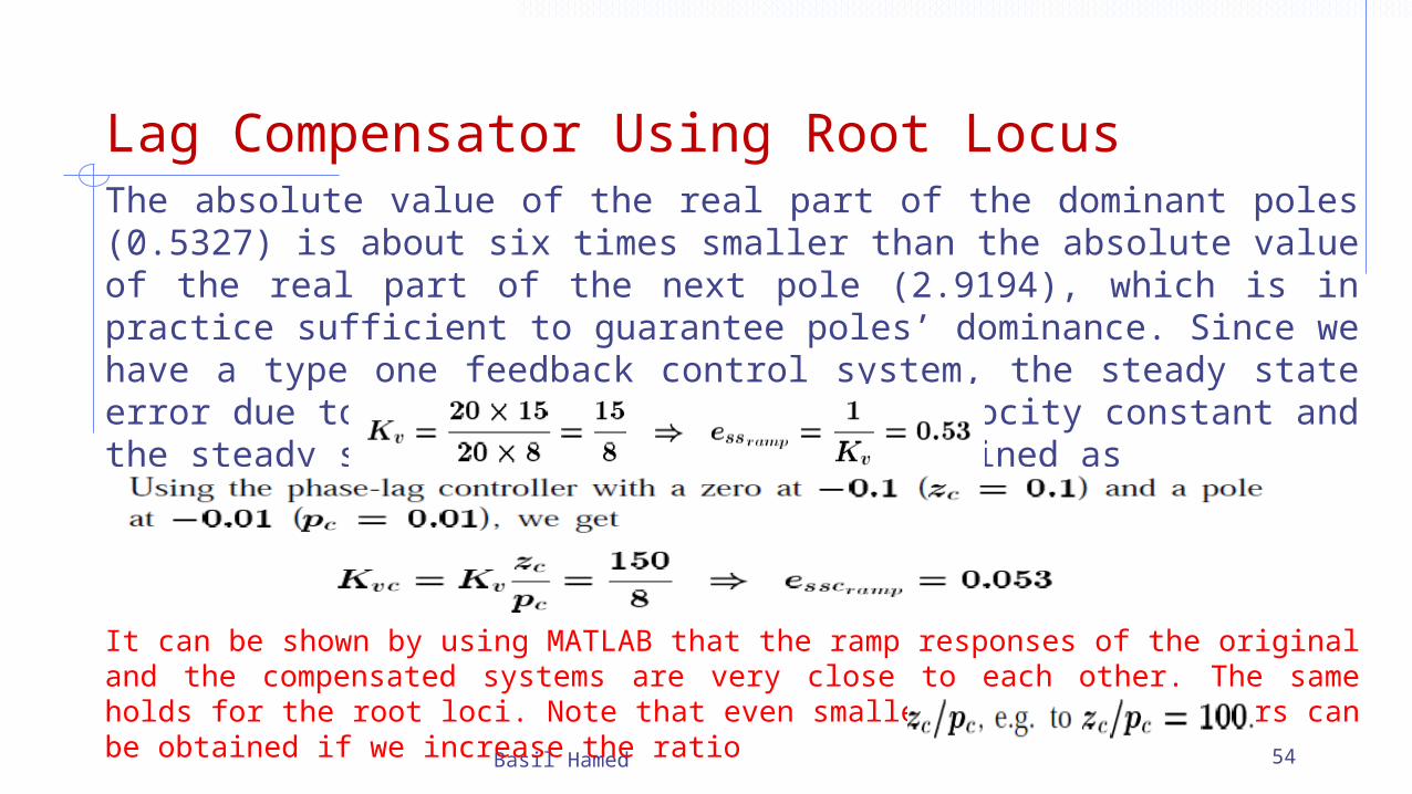
Lag Compensator Using Root LocusThe absolute value of the real part of the dominant poles (0.5327) is about six times smaller than the absolute value of the real part of the next pole (2.9194), which is in practice sufficient to guarantee poles’ dominance. Since we have a type one feedback control system, the steady state error due to a unit step is zero. The velocity constant and the steady state unit ramp error are obtained as
Basil Hamed 54
It can be shown by using MATLAB that the ramp responses of the original and the compensated systems are very close to each other. The same holds for the root loci. Note that even smaller steady state errors can be obtained if we increase the ratio
Lag Comp. Design via Root Locus
Basil Hamed 55
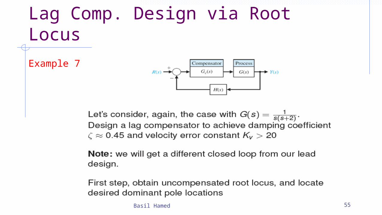
Example 7
Lag Comp. Design via Root Locus
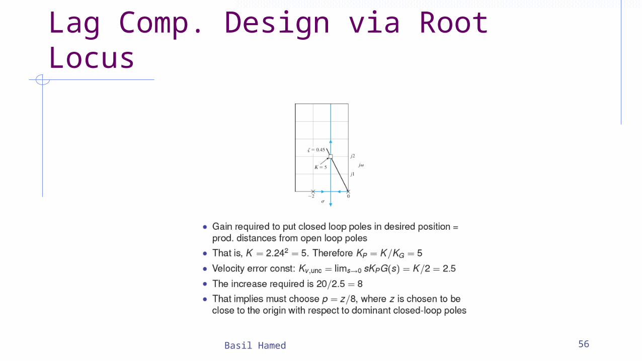
Basil Hamed 56
Lag Comp. Design via Root Locus
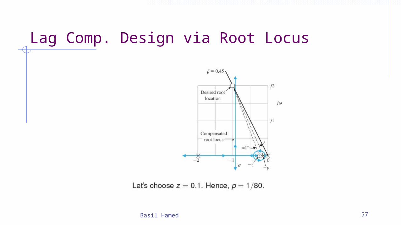
Basil Hamed 57
Lag Comp. Design via Root Locus
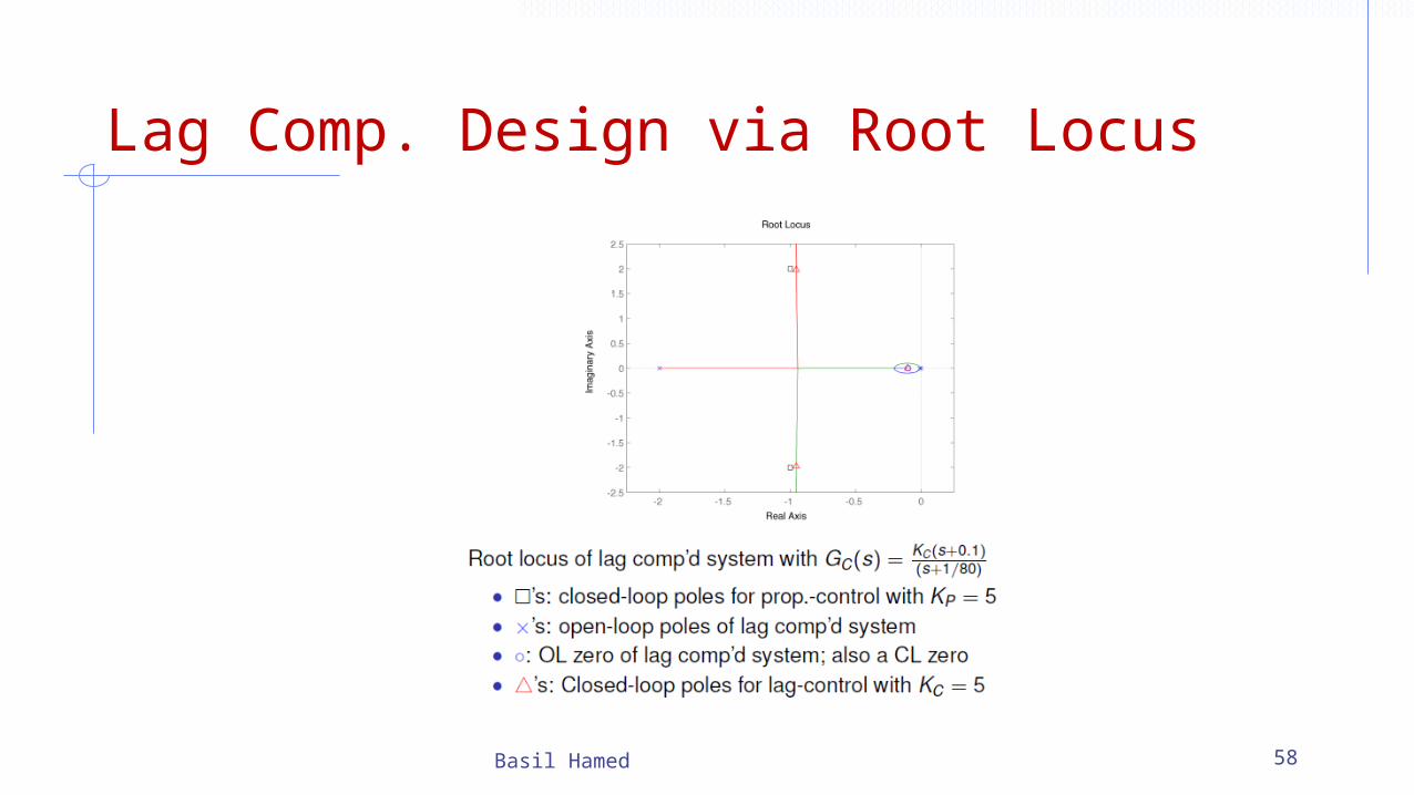
Basil Hamed 58
Lag Comp. Design via Root Locus
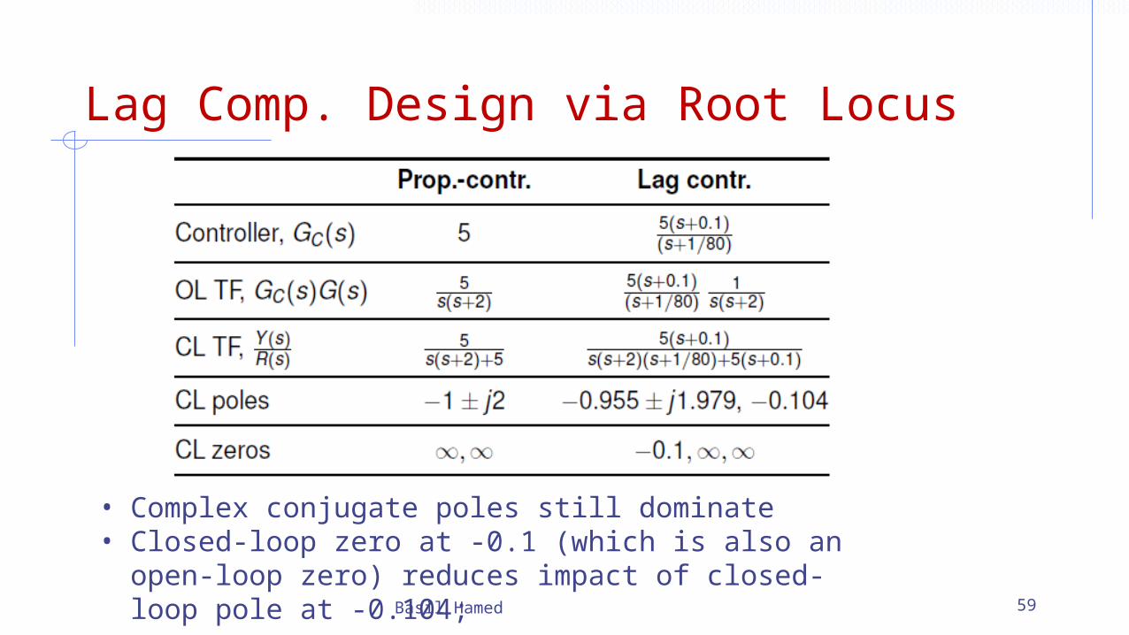
Basil Hamed 59
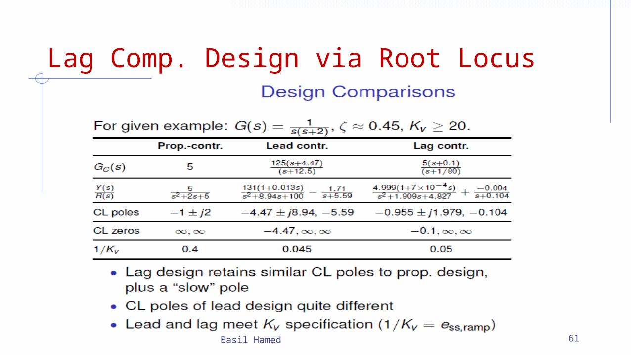
• Complex conjugate poles still dominate• Closed-loop zero at -0.1 (which is also an open-loop
zero) reduces impact of closed-loop pole at -0.104;
Lag Comp. Design via Root Locus
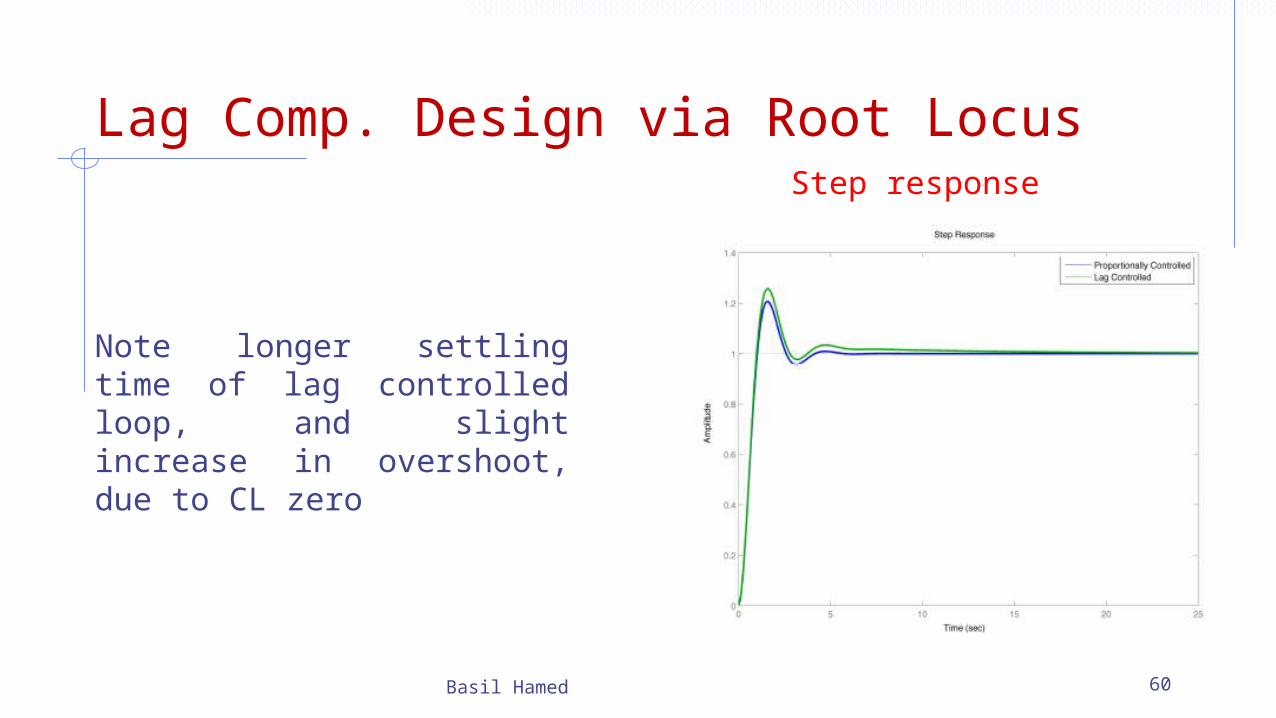
Basil Hamed 60
Note longer settling time of lag controlled loop, and slight increase in overshoot, due to CL zero
Step response
Lag Comp. Design via Root Locus
Basil Hamed 61
Lag Comp. Design via Root Locus
Basil Hamed 62
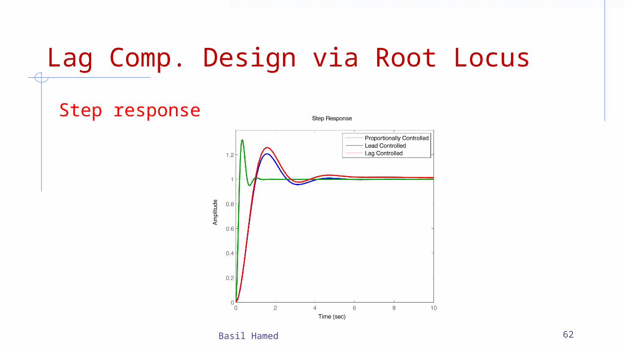
Step response

Lag Compensator Using Root Locus
• It was previously stated that lag controller should only minimally change the transient response because of its negative effect.
• If the phase-lag compensator is not supposed to change the transient response noticeably, what is it good for? The answer is that a phase-lag compensator can improve the system's steady-state response.
• It works in the following manner. At high frequencies, the lag controller will have unity gain. At low frequencies, the gain will be z0/p0 which is greater than 1.
• This factor z/p will multiply the position, velocity, or acceleration constant (Kp, Kv, or Ka), and the steady-state error will thus decrease by the factor z0/p0.
Basil Hamed 63

Lead-Lag Compensator
A lead-lag compensator combines the effects of a lead compensator with those of a lag compensator. The result is a system with improved transient response, stability and steady-state error. To implement a lead-lag compensator, first design the lead compensator to achieve the desired transient response and stability, and then add on a lag compensator to improve the steady-state response
Basil Hamed 64
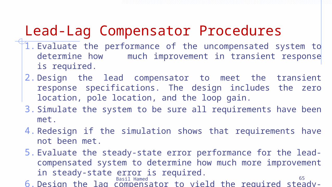
Lead-Lag Compensator Procedures1. Evaluate the performance of the uncompensated system to
determine how much improvement in transient response is required.
2. Design the lead compensator to meet the transient response specifications. The design includes the zero location, pole location, and the loop gain.
3. Simulate the system to be sure all requirements have been met.4. Redesign if the simulation shows that requirements have not been
met.5. Evaluate the steady-state error performance for the lead-
compensated system to determine how much more improvement in steady-state error is required.
6. Design the lag compensator to yield the required steady-state error.7. Simulate the system to be sure all requirements have been met.8. Redesign if the simulation shows that requirements have not been
met.
Basil Hamed 65
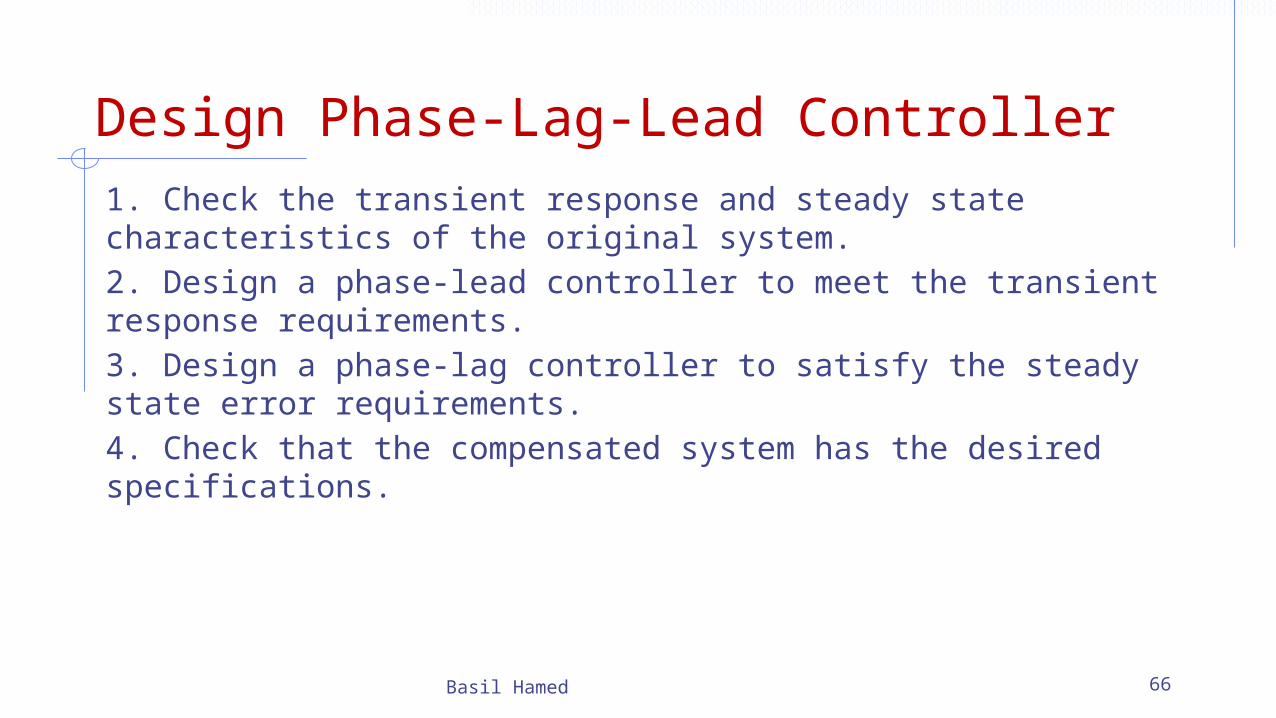
Design Phase-Lag-Lead Controller1. Check the transient response and steady state characteristics of the original system.2. Design a phase-lead controller to meet the transient response requirements.3. Design a phase-lag controller to satisfy the steady state error requirements.4. Check that the compensated system has the desired specifications.
Basil Hamed 66
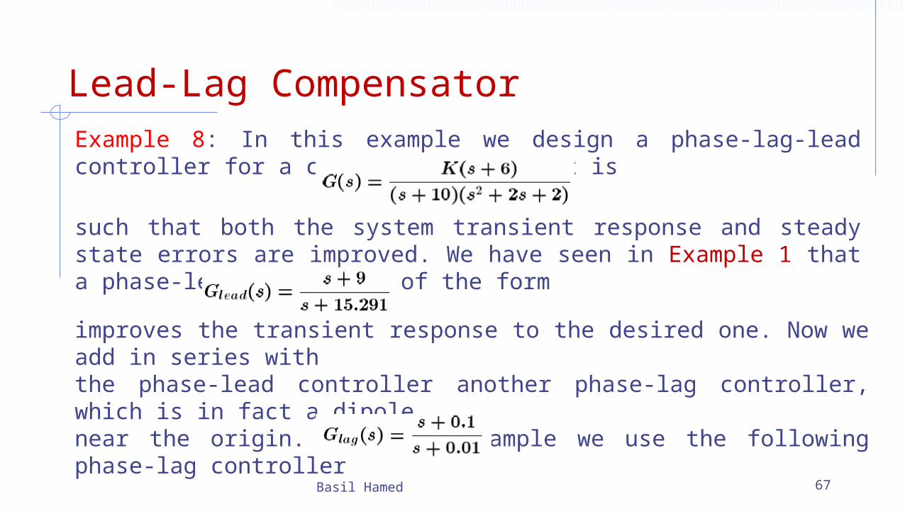
Lead-Lag Compensator Example 8: In this example we design a phase-lag-lead controller for a control system, that is
Basil Hamed 67
such that both the system transient response and steady state errors are improved. We have seen in Example 1 that a phase-lead controller of the form
improves the transient response to the desired one. Now we add in series withthe phase-lead controller another phase-lag controller, which is in fact a dipolenear the origin. For this example we use the following phase-lag controller
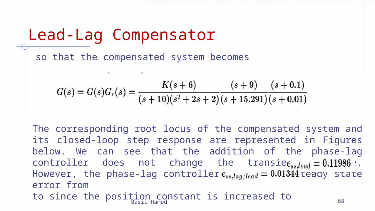
Lead-Lag Compensator so that the compensated system becomes
Basil Hamed 68
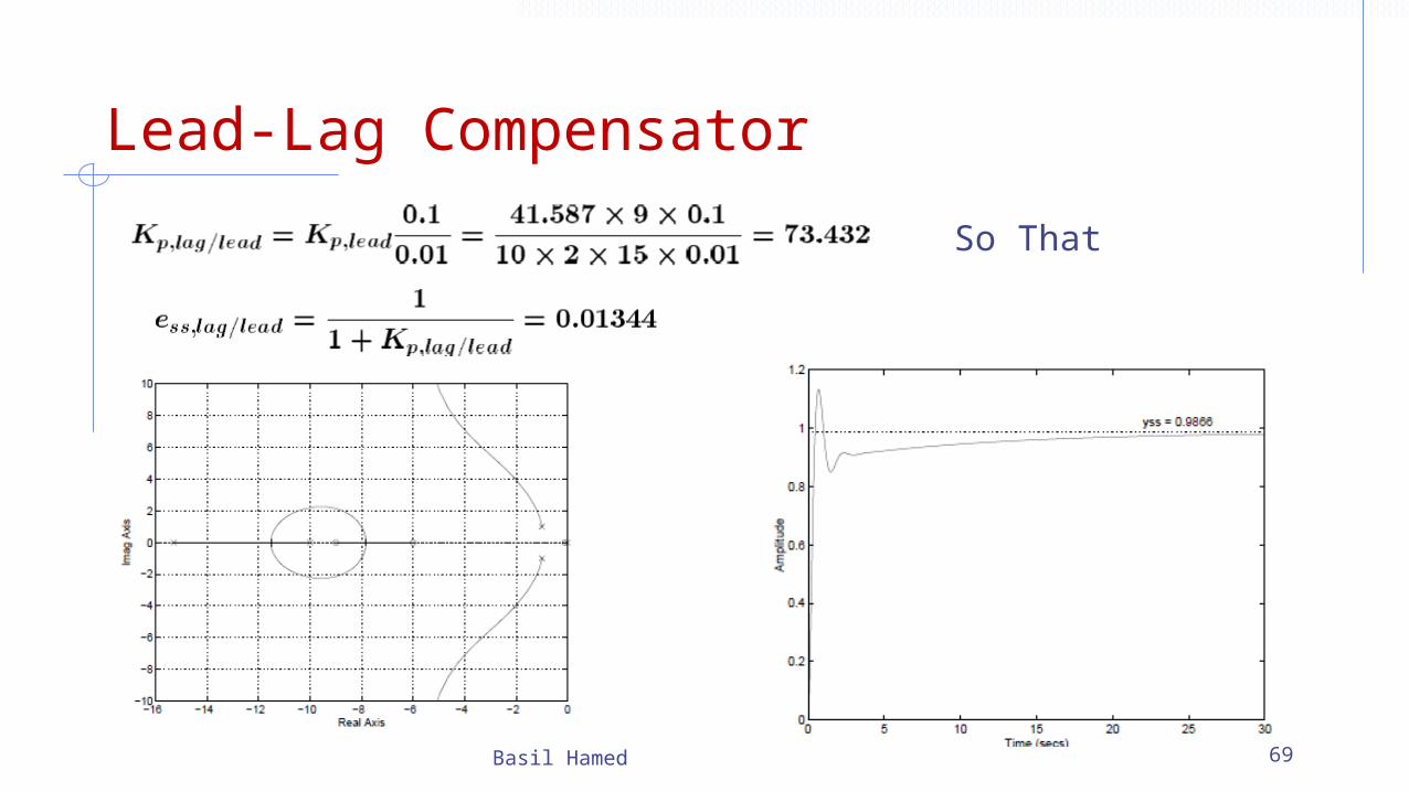
The corresponding root locus of the compensated system and its closed-loop step response are represented in Figures below. We can see that the addition of the phase-lag controller does not change the transient response. However, the phase-lag controller reduces the steady state error from to since the position constant is increased to
Lead-Lag Compensator
Basil Hamed 69
So That
HW 4
P 9.2, P 9.4, P 9.5, P 9.16, P 9.18, P 9.22, P 9.25
Due NEXT Class
Basil Hamed 70


