Download - Coolant Purification Systems
Coolant Purification Systems
GREEN ECO PRO CNC Coolant Purification Systems
Ultra 1200 INSTRUCTION MANUAL
Model: Ultra 1200
Serial No.
Manufacture Date:
Revision: E 2018
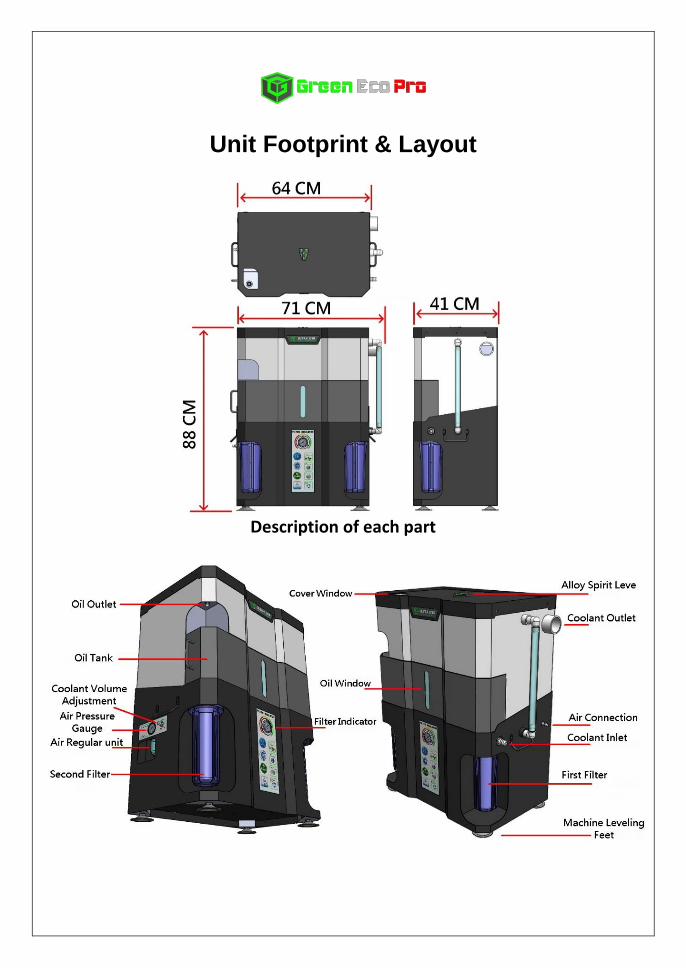
Unit Footprint & Layout
Description of each part
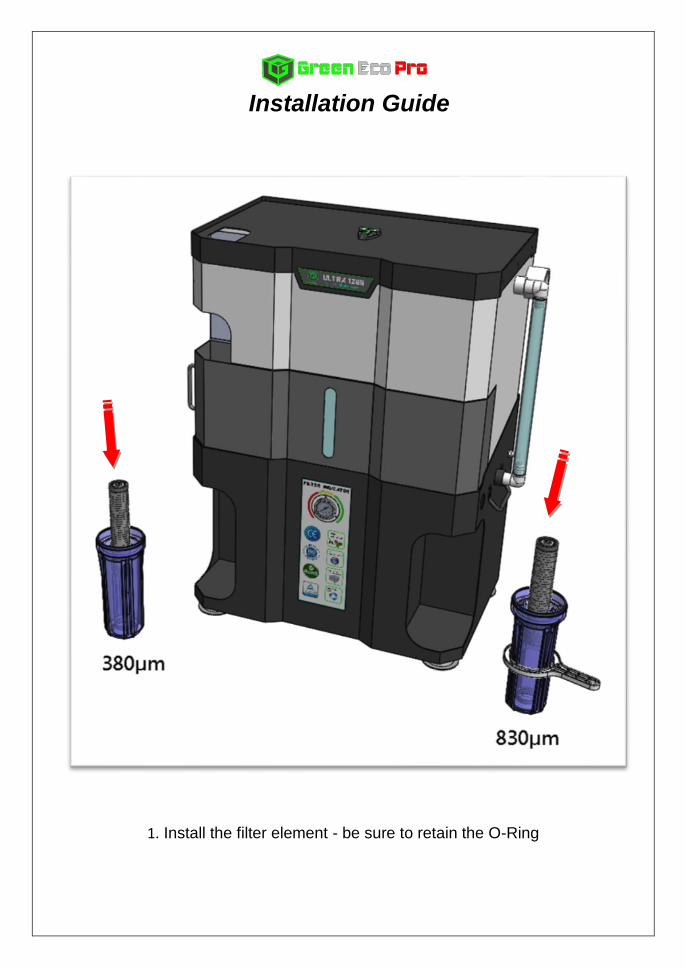
Installation Guide
1. Install the filter element - be sure to retain the O-Ring
Installation Guide
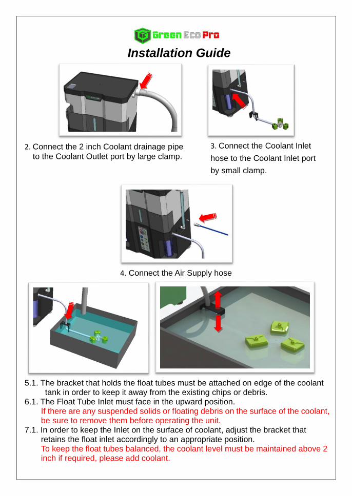
2. Connect the 2 inch Coolant drainage pipe
to the Coolant Outlet port by large clamp.
4. Connect the Air Supply hose
5.1. The bracket that holds the float tubes must be attached on edge of the coolant
tank in order to keep it away from the existing chips or debris. 6.1. The Float Tube Inlet must face in the upward position.
If there are any suspended solids or floating debris on the surface of the coolant, be sure to remove them before operating the unit.
7.1. In order to keep the Inlet on the surface of coolant, adjust the bracket that retains the float inlet accordingly to an appropriate position.
To keep the float tubes balanced, the coolant level must be maintained above 2 inch if required, please add coolant.
3. Connect the Coolant Inlet
hose to the Coolant Inlet port
by small clamp.
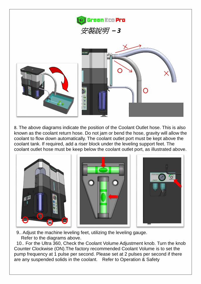
安裝說明 – 3
8. The above diagrams indicate the position of the Coolant Outlet hose. This is also
known as the coolant return hose. Do not jam or bend the hose, gravity will allow the coolant to flow down automatically. The coolant outlet port must be kept above the coolant tank. If required, add a riser block under the leveling support feet. The coolant outlet hose must be keep below the coolant outlet port, as illustrated above.
9.. Adjust the machine leveling feet, utilizing the leveling gauge. Refer to the diagrams above. 10.. For the Ultra 360, Check the Coolant Volume Adjustment knob. Turn the knob
Counter Clockwise (ON).The factory recommended Coolant Volume is to set the pump frequency at 1 pulse per second. Please set at 2 pulses per second if there are any suspended solids in the coolant. Refer to Operation & Safety
Installation Guide
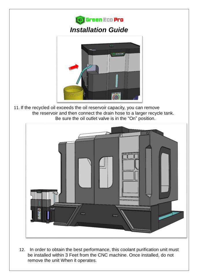
11. If the recycled oil exceeds the oil reservoir capacity, you can remove
the reservoir and then connect the drain hose to a larger recycle tank. Be sure the oil outlet valve is in the “On” position.
12. In order to obtain the best performance, this coolant purification unit must
be installed within 3 Feet from the CNC machine. Once installed, do not remove the unit When it operates.
Operation & Safety
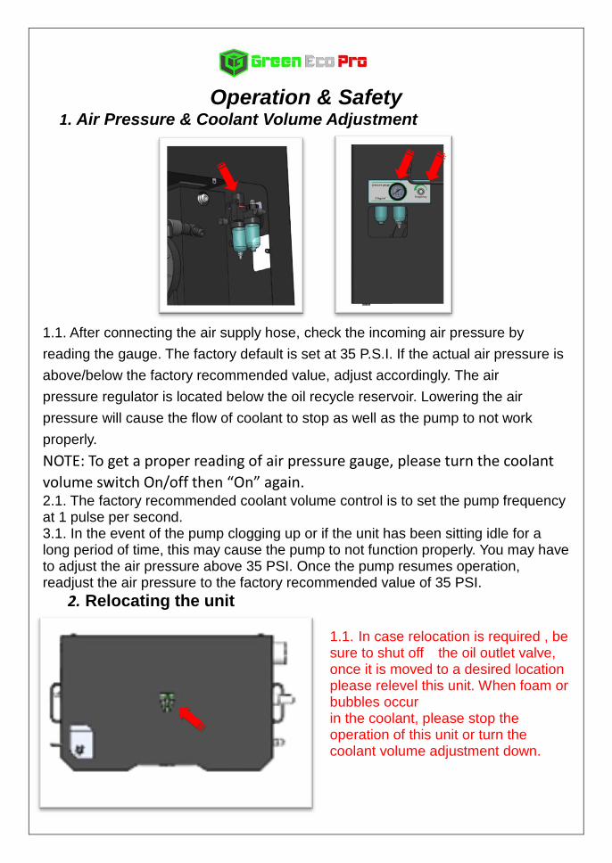
1. Air Pressure & Coolant Volume Adjustment
1.1. After connecting the air supply hose, check the incoming air pressure by
reading the gauge. The factory default is set at 35 P.S.I. If the actual air pressure is
above/below the factory recommended value, adjust accordingly. The air
pressure regulator is located below the oil recycle reservoir. Lowering the air
pressure will cause the flow of coolant to stop as well as the pump to not work
properly.
NOTE: To get a proper reading of air pressure gauge, please turn the coolant
volume switch On/off then “On” again. 2.1. The factory recommended coolant volume control is to set the pump frequency at 1 pulse per second. 3.1. In the event of the pump clogging up or if the unit has been sitting idle for a long period of time, this may cause the pump to not function properly. You may have to adjust the air pressure above 35 PSI. Once the pump resumes operation, readjust the air pressure to the factory recommended value of 35 PSI.
2. Relocating the unit
1.1. In case relocation is required , be sure to shut off the oil outlet valve, once it is moved to a desired location please relevel this unit. When foam or bubbles occur in the coolant, please stop the operation of this unit or turn the coolant volume adjustment down.
Operation & Safety – Page
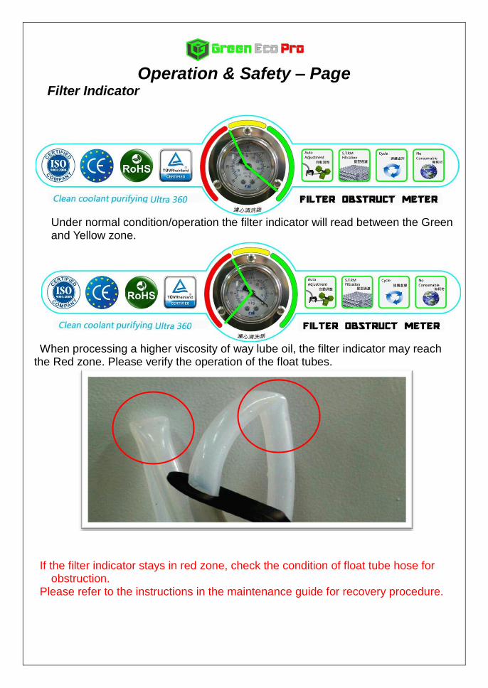
Filter Indicator
Under normal condition/operation the filter indicator will read between the Green and Yellow zone.
When processing a higher viscosity of way lube oil, the filter indicator may reach
the Red zone. Please verify the operation of the float tubes.
If the filter indicator stays in red zone, check the condition of float tube hose for
obstruction. Please refer to the instructions in the maintenance guide for recovery procedure.
Maintenance Guide - 1
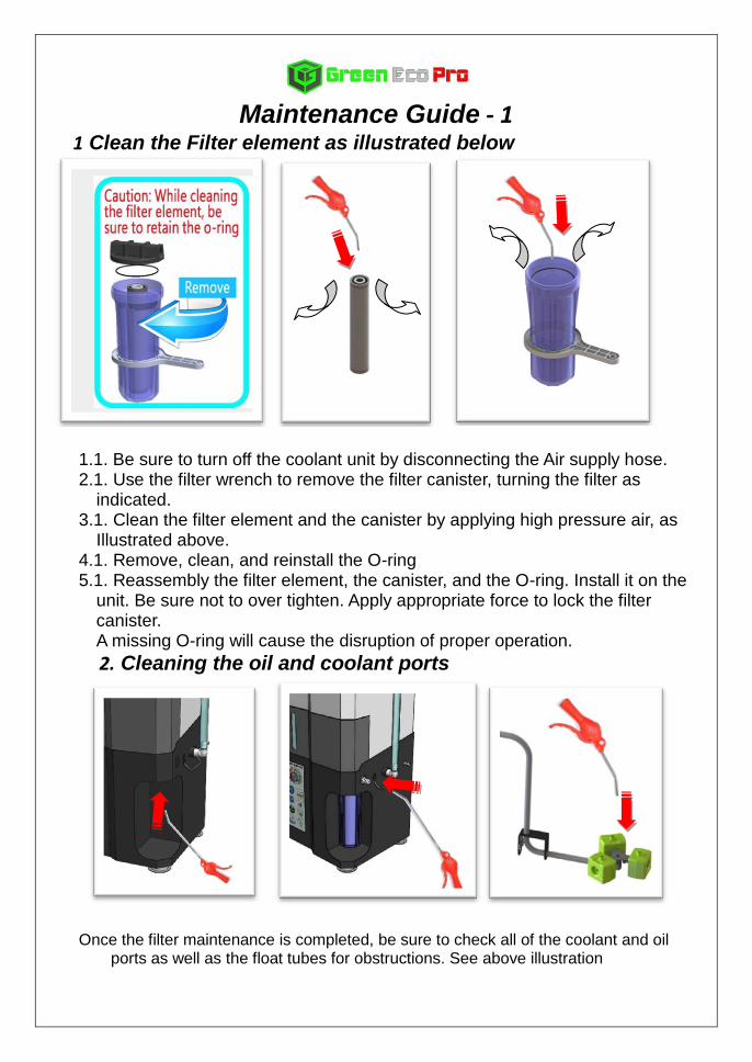
1 Clean the Filter element as illustrated below
1.1. Be sure to turn off the coolant unit by disconnecting the Air supply hose. 2.1. Use the filter wrench to remove the filter canister, turning the filter as
indicated. 3.1. Clean the filter element and the canister by applying high pressure air, as
Illustrated above. 4.1. Remove, clean, and reinstall the O-ring 5.1. Reassembly the filter element, the canister, and the O-ring. Install it on the
unit. Be sure not to over tighten. Apply appropriate force to lock the filter canister.
A missing O-ring will cause the disruption of proper operation.
2. Cleaning the oil and coolant ports
Once the filter maintenance is completed, be sure to check all of the coolant and oil ports as well as the float tubes for obstructions. See above illustration
Maintenance Guide - 2
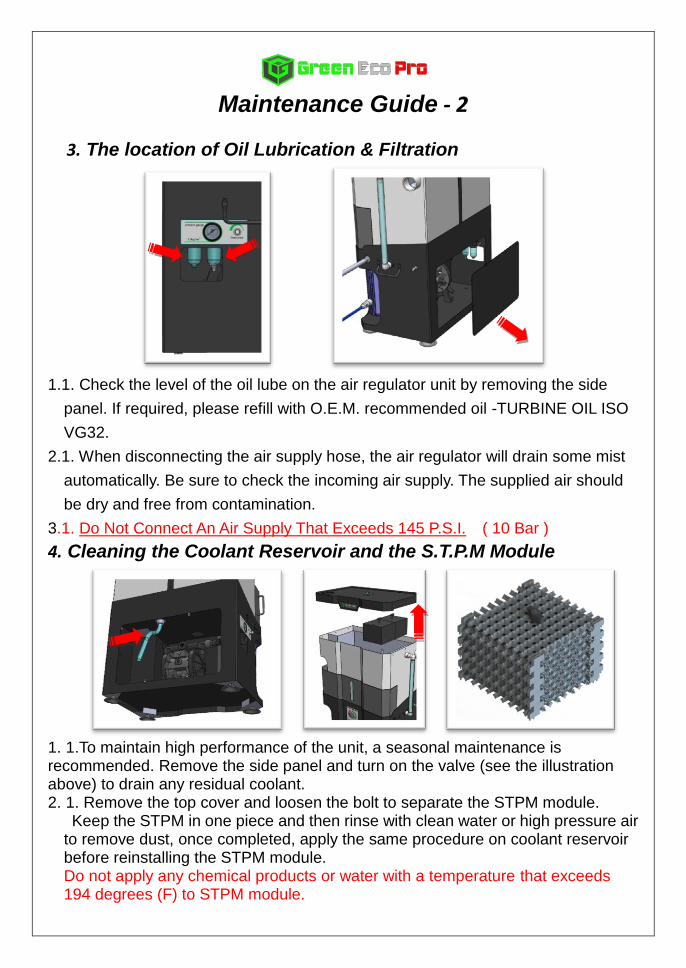
3. The location of Oil Lubrication & Filtration
1.1. Check the level of the oil lube on the air regulator unit by removing the side
panel. If required, please refill with O.E.M. recommended oil -TURBINE OIL ISO
VG32.
2.1. When disconnecting the air supply hose, the air regulator will drain some mist
automatically. Be sure to check the incoming air supply. The supplied air should
be dry and free from contamination.
3.1. Do Not Connect An Air Supply That Exceeds 145 P.S.I. ( 10 Bar )
4. Cleaning the Coolant Reservoir and the S.T.P.M Module
1. 1.To maintain high performance of the unit, a seasonal maintenance is recommended. Remove the side panel and turn on the valve (see the illustration above) to drain any residual coolant. 2. 1. Remove the top cover and loosen the bolt to separate the STPM module. Keep the STPM in one piece and then rinse with clean water or high pressure air
to remove dust, once completed, apply the same procedure on coolant reservoir before reinstalling the STPM module.
Do not apply any chemical products or water with a temperature that exceeds 194 degrees (F) to STPM module.
Faulty Recovery Procedure – Page 1
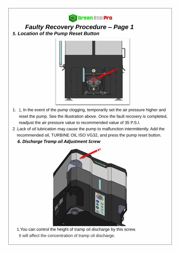
5. Location of the Pump Reset Button
1. 1. In the event of the pump clogging, temporarily set the air pressure higher and
reset the pump. See the illustration above. Once the fault recovery is completed,
readjust the air pressure value to recommended value of 35 P.S.I.
2 .Lack of oil lubrication may cause the pump to malfunction intermittently. Add the
recommended oil, TURBINE OIL ISO VG32, and press the pump reset button.
6. Discharge Tramp oil Adjustment Screw
1.You can control the height of tramp oil discharge by this screw.
It will affect the concentration of tramp oil discharge.
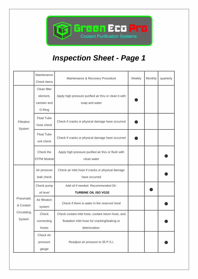
Inspection Sheet - Page 1
Maintenance
Check Items Maintenance & Recovery Procedure Weekly Monthly quarterly
Filtration
System
Clean filter
element,
canister and
O-Ring
Apply high pressure purified air thru or clean it with
soap and water ●
Float Tube
hose check Check if cracks or physical damage have occurred ●
Float Tube
unit check Check if cracks or physical damage have occurred ●
Check the
STPM Module
Apply high pressure purified air thru or flush with
clean water
●
Pneumatic
& Coolant
Circulating
System
Air pressure
leak check
Check air inlet hose if cracks or physical damage
have occurred
●
Check pump
oil level
Add oil if needed. Recommended Oil :
TURBINE OIL ISO VG32
●
Air filtration
system Check if there is water in the reservoir bowl
●
Check
connecting
hoses
Check coolant inlet hose, coolant return hose, and
floatation inlet hose for cracking/leaking or
deterioration. ●
Check Air
pressure
gauge
Readjust air pressure to 35 P.S.I.
●
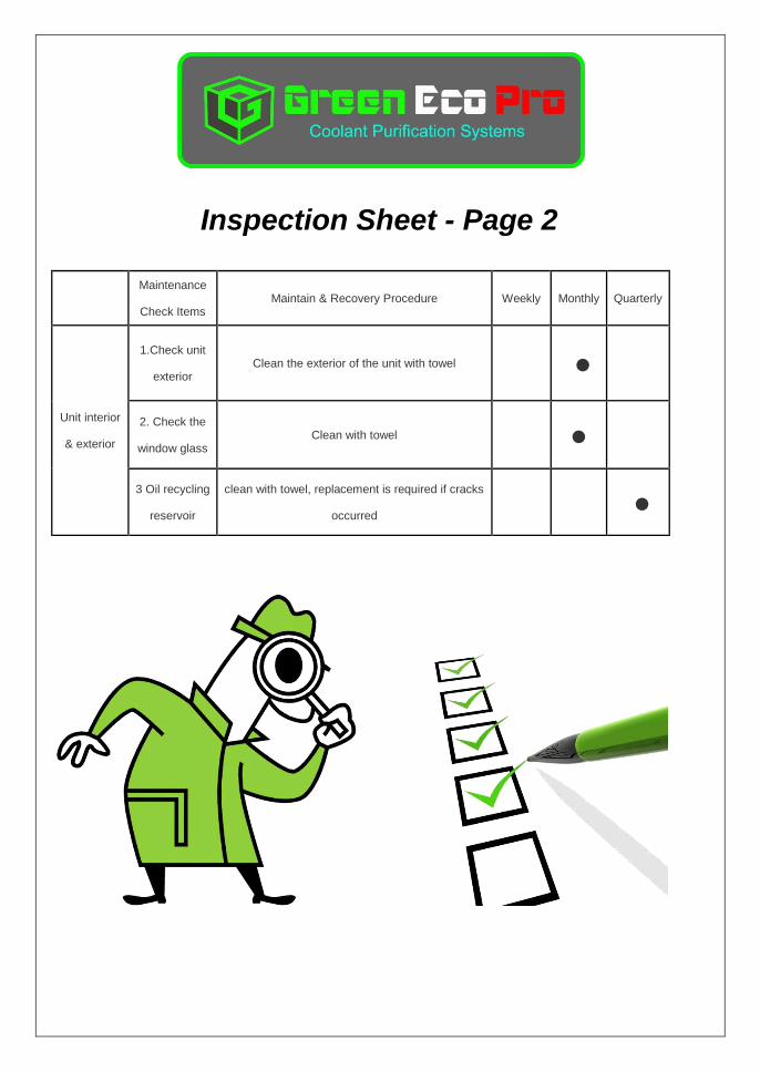
Inspection Sheet - Page 2
Maintenance
Check Items Maintain & Recovery Procedure Weekly Monthly Quarterly
Unit interior
& exterior
1.Check unit
exterior Clean the exterior of the unit with towel ●
2. Check the
window glass Clean with towel ●
3 Oil recycling
reservoir
clean with towel, replacement is required if cracks
occurred ●
WARRANTY STATEMENT
Terms & Conditions In the event that a fault occurs with the machine or any parts supplied with it due to workmanship or defective materials, Green Eco Pro will replace any faulty components (other than consumable components) for a period of 12 months from the date of installation. Provided the following:
1. You have notified us of the relevant fault within 7 days of discovering it.
2. The machine has been used in accordance with our instructions.
3. The fault is not due to reasonable wear and tear and does not relate to consumable components (including, without limitation, filters, filter element, hand tool,O-ring).
4. Should the machine require relocation, make sure that the oil outlet valve is in the Off position. Relocate and level the unit. Otherwise, while cycling, the coolant purification unit shall not be moved.
5. We shall be entitled to have returned any components replaced by us under this warranty.
6. The warranty shall be deemed void if the customer or a third party modifies or repairs the equipment without having Green Eco Pro’s previous approval.
The warranty offered on these products provides coverage against defective parts or faulty
workmanship subjected to all routine maintenance and run up procedures being observed
and carried out within these periods as detailed by Green Eco Pro Co.
The warranty does not cover for replacements in the event of accidental such as natural
disasters or malicious damage or damage caused by misuse of the product.
Part Warranty With the exception of easily worn parts mentioned above, all other repair parts, when replaced, shall have a 6 month factory warranty period on the part itself regardless of the machine warranty term.


