Download - CREW AND THERMAL SYSTEMS DIVISION

CREW AND THERMAL SYSTEMS DIVISION NASA - LYNDON B. JOHNSON SPACE CENTER
Hazard Analysis for
the Mark III Space Suit Assembly (SSA) Used in One-g Operations
DOCUMENT NUMBER, REV
CTSD-ADV-590, Rev. C
DATE
August 1, 2012
PREPARED BY: Eng / Dana Valish
REVIEWED BY: Eng / Richard Rhodes
APPROVED BY: EC5 / Raul Blanco
APPROVED BY: NS / Art Wood
No. Of Pages: 25 REVISIONS
REVISION PREPARER APPROVALS AUTHORZIED
LETTER/DATE BRANCH SAFETY
Baseline/ 5-21-2010 A/ 8-25-2010 B/ 8-2-2011 C/ 8-1-2012
S. Anderson K. Mitchell K. Mitchell D. Valish
C. Dinsmore R. Blanco R. Blanco R. Blanco

CTSD-ADV-590, Rev. B Hazard Analysis for Mark III Space Suit Assembly Used in One-g Standard Operations
Date: 8-2-2011 Page 2 of 25
Rev/Date Change Log
A/ 8-25-2010 Added Change Log
Revised the document title.
Updated information on the various suit configurations
Updated HA to have new 7-scale RAC codes
Re-baselined HA information for consistency across all documentation
B/ 8-2-2011 Added suit pressures table
Updated Communication System section with more detailed comm. information and added SPACIS II as an approved comm. system
Added polar heart rate monitor and Zephyr as approved ancillary equipment.
Updated hazard summary and table to be consistent across suits.
C/ 8-1-2012 Added information about colored Ortman wires and their length to
aid in the verification of correct Ortman wire being installed
Added suit weight

CTSD-ADV-590, Rev. B Hazard Analysis for Mark III Space Suit Assembly Used in One-g Standard Operations
Date: 8-2-2011 Page 3 of 25
1.0 Introduction
This Hazard Analysis document encompasses the Mark III Space Suit Assembly (SSA) and associated ancillary equipment. It has been prepared using JSC17773, "Preparing Hazard Analyses for JSC Ground Operation", as a guide.
2.0 Purpose
The purpose of this document is to present the potential hazards involved in ground (23 % maximum O2, One-g) operations of the Mark III and associated ancillary support equipment system. The hazards listed in this document are specific to suit operations only; each supporting facility (Bldg. 9, etc.) is responsible for test specific Hazard Analyses. A "hazard" is defined as any condition that has the potential for harming personnel or equipment.
3.0 Scope
This analysis was performed to document the safety aspects associated with manned use of the Mark III for pressurized and unpressurized ambient, ground-based, One-g human testing. The hazards identified herein represent generic hazards inherent to all standard JSC test venues for nominal ground test configurations. Non-standard test venues or test specific configurations may warrant consideration of additional hazards analysis prior to test. The cognizant suit engineer is responsible for the safety of the astronaut/test subject, space suit, and suit support personnel. The test requester, for the test supported by the suit test engineer and suited subject, is responsible for overall safety and any necessary Test Readiness Reviews (TRR).
For the purpose of the baseline document the following information was used:
Test personnel are available and trained to extract the test subject in the event of an emergency.
This Hazard Analysis is restricted to Mark III testing in an ambient pressure environment.
The term ‗One-g‘ in this document refers to any dry, ground-based test.
4.0 Space Suit Configuration
The Mark III hardware and ancillary support equipment provides the necessary functions and interfaces to conduct manned pressurized suit operations when combined with (a) a suitable gas supply system, (b) cooling water supply and (c) suitable communication system.
The Mark III is a one of a kind technology demonstrator, originally designed as a zero-
CTSD-ADV-590, Rev. B Hazard Analysis for Mark III Space Suit Assembly Used in One-g Standard Operations
Date: 8-2-2011 Page 4 of 25
pre-breathe suit. Over time the suit has evolved to include several different configurations. The operating pressures of the various configurations range up to 8.3 psid to provide a crewmember/test subject with the mobile pressure enclosure necessary to perform the required activities. The Mark III uses a rear entry hatch. The suit weighs 121 lbs.
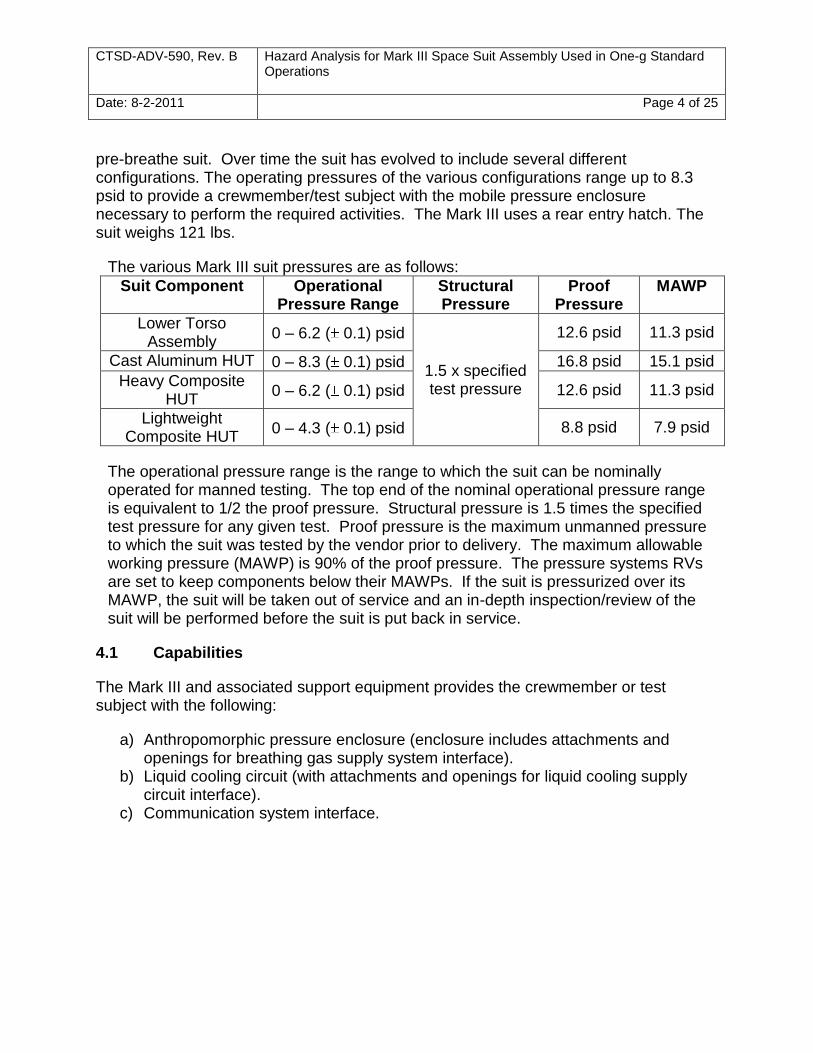
The various Mark III suit pressures are as follows:
Suit Component Operational Pressure Range
Structural Pressure
Proof Pressure
MAWP
Lower Torso Assembly
0 – 6.2 ( 0.1) psid
1.5 x specified test pressure
12.6 psid 11.3 psid
Cast Aluminum HUT 0 – 8.3 ( 0.1) psid 16.8 psid 15.1 psid
Heavy Composite HUT
0 – 6.2 ( 0.1) psid 12.6 psid 11.3 psid
Lightweight Composite HUT
0 – 4.3 ( 0.1) psid 8.8 psid 7.9 psid
The operational pressure range is the range to which the suit can be nominally operated for manned testing. The top end of the nominal operational pressure range is equivalent to 1/2 the proof pressure. Structural pressure is 1.5 times the specified test pressure for any given test. Proof pressure is the maximum unmanned pressure to which the suit was tested by the vendor prior to delivery. The maximum allowable working pressure (MAWP) is 90% of the proof pressure. The pressure systems RVs are set to keep components below their MAWPs. If the suit is pressurized over its MAWP, the suit will be taken out of service and an in-depth inspection/review of the suit will be performed before the suit is put back in service.
4.1 Capabilities
The Mark III and associated support equipment provides the crewmember or test subject with the following:
a) Anthropomorphic pressure enclosure (enclosure includes attachments and openings for breathing gas supply system interface).
b) Liquid cooling circuit (with attachments and openings for liquid cooling supply circuit interface).
c) Communication system interface.
CTSD-ADV-590, Rev. B Hazard Analysis for Mark III Space Suit Assembly Used in One-g Standard Operations
Date: 8-2-2011 Page 5 of 25
4.2 External Interfaces
The Mark III has three main external interfaces: breathing gas, cooling water and a communications system.
4.2.1 Breathing Gas
The Mark III is designed to receive certified breathing air at 5 – 6 ACFM (actual cubic feet per minute) to both inflate the pressure garment and provide a breathable atmosphere for the suit subject. The breathing air is delivered to the pressure garment via a certified gaseous breathing air system. The air enters the pressure garment at the connection located on the top, center of the rear entry hatch (‗Air In‘) and is routed into the helmet by the Mark III HUT Vent Duct. The return air (exhalent) is removed from the suit at the ‗Air Out‘ connection located on the top, right of the rear entry hatch. Both the supply and return air connectors are Class III Apollo style connectors. A back-pressure regulator (BPR), with a pressure gauge which reads from 0-15 psig, is positioned on the suit breathing air exhaust line and is used to adjust suit pressure.
4.2.2 Cooling Water
The Mark III receives cooling from an external source, and has a cooling line pass-thru located on the top, left of the rear entry hatch, which allows the modified shuttle liquid cooling garment (LCG) cooling lines to be routed through the fitting. On the inside of the pressure garment, the cooling lines are routed directly to the main LCG lines via 0.375‖ PVC tubing fitted with standard self-sealing quick disconnects.
4.2.3 Communications
The Mark III contains its own internal communications system to receive and deliver audio from and to the suit test team. The in-suit speakers, attenuator, amplifier box and associated wiring are housed behind a protective cover in the hatch. A hard mounted microphone system resides along the suit-side neck ring to provide off-human communications. The internal communications set-up also allows for connection of an ear-bud. The internal system connects to one of three external communications systems that actually provide the system power and signal processing via a Bendix connector on the suit rear hatch.
The Space Suit Audio Communication Interface System (SPACIS) is the primary external comm. interface for space suit testing. The Mark III is approved for use with both SPACIS I and II. Configuration of the SPACIS and associated communication hardware is documented in CTSD-ADV-819: Hazard Analysis for Spacesuit Audio Communication Interface System. The SPACIS system has a line level speaker output and is designed to interact with either the single-channel or four-channel amplifiers. The microphone input is designed for 600 Hz electret microphones.
CTSD-ADV-590, Rev. B Hazard Analysis for Mark III Space Suit Assembly Used in One-g Standard Operations
Date: 8-2-2011 Page 6 of 25
Technicians and operators primarily connect to SPACIS utilizing the RSwo-601 belt packs. In lab environments, the external speaker can be used to broadcast two-way comm. to the entire test team real-time. The suit is connected utilizing a communication line that runs underneath the breathing air and cooling umbilical sheath.
The Advanced EVA (AEVA) Communications System is an alternate communication system is a wireless cable-free, battery operated portable system that is integrated into the Liquid Air Backpack. This system is used where cable free operations are required, such as the rockyard or other remote field locations. A complete description of this system and a specific configuration description can be found in CTSD-ADV-563: AEVA Communications System Hazard Analysis Report.
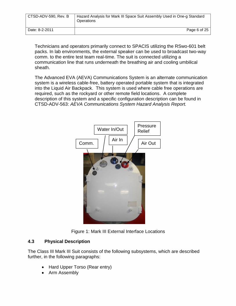
Figure 1: Mark III External Interface Locations
4.3 Physical Description
The Class III Mark III Suit consists of the following subsystems, which are described further, in the following paragraphs:
Hard Upper Torso (Rear entry)
Arm Assembly
Water In/Out
Air In Air Out
Pressure Relief
Comm..
CTSD-ADV-590, Rev. B Hazard Analysis for Mark III Space Suit Assembly Used in One-g Standard Operations
Date: 8-2-2011 Page 7 of 25
Lower Torso Assembly
Helmet
Glove Assembly
Ancillary Support Equipment
4.3.1 Hard Upper Torso (Rear entry):
The hard upper torso (HUT) consists of the HUT itself, a detachable rear hatch, helmet disconnect, and a breech lock design attachment to the lower torso. It utilizes Apollo type inlet/outlet gas connectors, a cooling water connector and an Apollo type relief valve. The external interface hardware is located on the upper center of the hatch, as shown in Figure 1. The Mark III HUT Vent Duct is used to direct airflow into the helmet. The locking mechanism for securing the hatch to the HUT is a breech lock design with the locking lever located in front center just above the waist. A shoulder harness is used in the suit.
4.3.2 Arm Assembly:
The left and right arm assemblies are flexible, anthropomorphic pressure vessels of heat sealed urethane coated nylon bladder fabric enclosed in polyester restraint fabric. The heat sealed seams in the bladder are over-taped on the inner surface with nylon bladder fabric coated on both sides with urethane and attached by heat sealing. Each arm has a bearing at the Scye opening and also between the upper and lower arm. The upper and lower arm is secured together by a 19 1/4‖ long Ortman wire. The arm Ortman wire is color coded blue at the exposed end so that it is easily identifiable. A wrist disconnect is secured to the lower arm by a 16‖ Ortman wire, which is color coded orange. The bladder and restraint fabric are flange mounted. Fully redundant axial primary and secondary restraint line webbings are provided to carry the axial loads between the flanges on the lower arm. The primary shoulder used on the Mark III Space Suit is a rolling convolute with link attachments for each convolute. The 4 bearing Air-Lock composite shoulders (operational
pressure range 0 – 4.3 0.1 psid) can also be used on the Mark III with an adapter. A cover layer is provided for each upper and lower arm.
4.3.3 Lower Torso Assembly:
The lower torso assembly (LTA) consists of waist, brief, hip/thigh, leg and boot
assemblies, and has an operational pressure range of 0 – 6.2 0.1 psid.
Waist assembly:
The waist consists of a breech lock adapter to mate with the HUT and an optional waist bearing. It has a rolling convolute and pivot points on each side to allow for flexion/extension at the waist. The pivot points are attached to a brief.
CTSD-ADV-590, Rev. B Hazard Analysis for Mark III Space Suit Assembly Used in One-g Standard Operations
Date: 8-2-2011 Page 8 of 25
Brief Assembly:
The brief assembly is a composite piece attached to the waist by the convolute fabric and pivot points. It has two leg openings to accommodate the hip/thigh assembly.
Hip/Thigh Assembly:
The hip/thigh assembly is made of composite material and consists of two transition elements joined together by three bearings secured with Ortman wires to each other. It is secured to the brief assembly by an Ortman wire. The lower bearing incorporates a thigh adduction/abduction joint, and is attached to a flange to accommodate the leg assembly.
Leg Assembly:
The leg assembly consists of heat-sealed urethane coated nylon bladder and Dacron restraint fabric. The heat sealed seams in the bladder are over-taped to the inner surface with nylon bladder fabric coated on both sides with urethane and attached to the bladder by heat sealing. Fully redundant axial primary and secondary restraint line webbings attach to the flange mounts on both ends of the leg assembly. The leg is secured to the hip/thigh assembly with Ortman wires.
Boot Assembly:
The Mark III can operate with three different boot assemblies, as described below:
Zero Pre-Breathe Boot
The Zero Pre-Breathe Boot assembly has the same interior soft-good construction as the shuttle boot; however the outer (restraint) layer consists of a standard work boot sole and leather upper portion attached to a soft ankle convolute.
David Clark Boot
The David Clark Boot assembly has a Gore-tex bladder with a 400 denier Nomex upper which incorporates patterned convolutes for flexion/extension. The boot assembly has an instep strap for indexing the foot and a standard work boot sole.
Self Adjustable REI Boot
The Self Adjustable REI Boot assembly is an REI suit boot which has been modified to be self adjustable while at pressure. The boot uses a

CTSD-ADV-590, Rev. B Hazard Analysis for Mark III Space Suit Assembly Used in One-g Standard Operations
Date: 8-2-2011 Page 9 of 25
commercial-off-the-shelf (COTS) Boa™ device for instep sizing and has the option of two different modified COTS booties for indexing the foot within the boot. The boot uses an adapter ring to allow it to interface with the Mark III ankle bearing.
All three boot assemblies connect with either a composite or an aluminum ankle bearing, which secure the boot to the leg assembly with a 20 3/8‖ Ortman wire. The boot disconnect Ortman wire is color coded white at the exposed end.
4.3.4 Helmet:
The Mark III can be configured with two different helmets, a 13 inch or 14 inch diameter hemispherical dome. Both helmets consist of a detachable, transparent hard pressure vessel encompassing the head and include the passive disconnect for attachment to the HUT with a 42 7/8‖ Ortman wire fitting.
4.3.5 Glove Assembly:
The Mark III lower arm-to-glove interface is a Shuttle Extravehicular Mobility Unit (EMU) style suit side wrist disconnect. The Mark III can be used with approved glove configurations which interface with this wrist disconnect. The gloves used with the Mark III shall not be taken above their specified MAWP.
4.3.6 Ancillary Support Equipment
Liquid Cooling Garment (LCG):
A modified SSA LCG is used with the Mark III. It is a conformal garment, which is worn whenever the suit is worn. It has ethylene vinyl acetate tubing, woven through the spandex restraint cloth. Cooling water circulates through the tubing, near the skin.
Thermal Comfort Undergarment (TCU):
The TCU is a two piece (top and bottom) crew optional underclothing. The TCU is worn under the LCG to improve crew comfort and hygiene.
Polar Heart Rate Monitor/Zepher Bioharness
The Polar Hearth Rate Monitor may be worn during suited testing to monitor the test subject‘s heart rate.
The Zepher Bioharness may also be worn during suited testing. The Zephyr Bioharness is a sensor strap with a transmitter and data logging memory capability used for physiological monitoring. The Zephyr records heart rate,
CTSD-ADV-590, Rev. B Hazard Analysis for Mark III Space Suit Assembly Used in One-g Standard Operations
Date: 8-2-2011 Page 10 of 25
breathing, posture (attitude of device in degrees from vertical), skin temperature, and activity and has a transmit range up to 100 m (50 feet), environment and antenna dependent.
Mark III Donning Stand
The Mark III donning stand secures the suit at the waist front to allow for rear entry. Height adjustment of the stand is motor driven and can be adjusted by the suited crewman. Annual loads certification testing is performed to a safe working load of 500 lbs (1000 lb proof load test). The donning stand also consists of the donning stairs, which are also load certified to a safe working load of 250 lbs (500 lb proof load test). The stairs lock into the donning, and allow the subject to climb up to the rear entry hatch level during donning.
5.0 Applicable Documents
JPR-1700.1 JSC Safety and Health Handbook
JSC-17773 Preparing Hazard Analyses for JSC Ground Operations
STB-BB-121 Failure Modes and Effects Analysis for the EMU Laboratory Pressure Garment Assembly Test Stands
STB-HA-121 Hazard Analysis for the EMU Laboratory Pressure Garment Assembly (PGA) Test Stands
STB-F-412 Breathing Air Tube Trailer Charging and Sampling Procedure
CTSD-ADV-197 Standard Operating Procedure for the Mark III Space Suit Assembly (SSA) Used in One-g Operations
CTSD-ADV-230 Fit Check Procedure for the Mark III Space Suit Assembly (SSA)
CTSD-ADV-298 Mark III Space Suit Assembly Maintenance and Repair
Manual
CTSD-ADV-563 AEVA Communications System Hazard Analysis Report
CTSD-ADV-652 Communications, Avionics, and Informatics Pack and LAB Data Acquisition System Hazard Analysis Report
CTSD-ADV-590, Rev. B Hazard Analysis for Mark III Space Suit Assembly Used in One-g Standard Operations
Date: 8-2-2011 Page 11 of 25
CTSD-ADV-801 Integrated Hazard Analysis for Use of the B34 Portable Cooling Box (PCB) Used in 1-G and Reduced Gravity Aircraft Evaluations with Prototype Space Suits
CTSD-ADV-818 Determination of Residual Carbon Dioxide During Forced Ventilation of a Hemispherical Space Suit Helmet
CTSD-ADV-819 Hazard Analysis for the Space Suit Audio Communication Interface System (SPACIS)
CTSD-ADV-822 Building 34 Structural Test of CEI Using PGA Test Stand
CTSD-ADV-823 Building 34 Leakage Test of CEI/TARE of the PGA Test Stand
CTSD-ADV-824 Building 34 Ground Cooling Cart Checkout and Operating Procedure
CTSD-ADV-869 Integrated Hazard Analysis for the Advanced Suit Hardware and the Building 34 PGA Test Stand
CTSD-ADV-907 Integrated Hazard Analysis for the Advanced Suit Hardware and the Building 34 LPO K-Bottle Manifold
L16-M00001 PGA/GSL Test Stand Hardware Fixtures
L20-M00002 Ground Support Equipment Test Support Hardware Integration Drawing
CTSD-ADV-590, Rev. B Hazard Analysis for Mark III Space Suit Assembly Used in One-g Standard Operations
Date: 8-2-2011 Page 12 of 25
6.0 Summary of Hazards
6.1 Hazard Identification Criteria
This report is prepared in accordance with JSC17773, "Preparing Hazard Analyses for JSC Ground Operation". The ―hazards‖ or "potential hazards" identified in this analysis came from the following sources:
Facility ―walk-through‖ inspection
Hardware inspection
System Design Drawings
Discussion with Facility/SSA Engineers and Technicians
Each potential hazard identified from these criteria is documented on the attached Hazard Analysis Worksheets. Each work sheet identifies a potential hazard, lists what causes that hazard to exist and states what measures have been taken to control or minimize that hazard. It gives a numerical representation of what level or degree of severity the hazard is rated by the analyzer and also lists the probability of the occurrence before and after mitigation.
The following definitions are vital to an understanding of the requirements contained in this document:
a. Hazard — An unsafe or unhealthful condition that could lead to a mishap if it is not corrected.
b. Consequence — The subjective estimate of worst credible outcome in terms of potential personnel injury, equipment/facility damage, and monetary losses. Consequence severity classes are defined as follows.
Class I - Catastrophic.
A condition that may cause death or permanently disabling injury, facility destruction on the ground, or loss of crew, major systems, or vehicle during the mission; schedule slippage causing launch window to be missed; cost overrun greater than 50% of planned cost.
Class II - Critical.
A condition that may cause severe injury or occupational illness, or major property damage to facilities, systems, equipment, or flight hardware; schedule slippage causing launch date to be missed; cost overrun between 15% and not exceeding 50% of planned cost.
CTSD-ADV-590, Rev. B Hazard Analysis for Mark III Space Suit Assembly Used in One-g Standard Operations
Date: 8-2-2011 Page 13 of 25
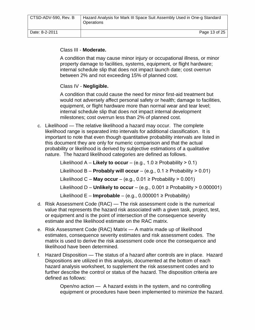
Class III - Moderate.
A condition that may cause minor injury or occupational illness, or minor property damage to facilities, systems, equipment, or flight hardware; internal schedule slip that does not impact launch date; cost overrun between 2% and not exceeding 15% of planned cost.
Class IV - Negligible.
A condition that could cause the need for minor first-aid treatment but would not adversely affect personal safety or health; damage to facilities, equipment, or flight hardware more than normal wear and tear level; internal schedule slip that does not impact internal development milestones; cost overrun less than 2% of planned cost.
c. Likelihood — The relative likelihood a hazard may occur. The complete likelihood range is separated into intervals for additional classification. It is important to note that even though quantitative probability intervals are listed in this document they are only for numeric comparison and that the actual probability or likelihood is derived by subjective estimations of a qualitative nature. The hazard likelihood categories are defined as follows.
Likelihood A – Likely to occur – (e.g., 1.0 ≥ Probability > 0.1)
Likelihood B – Probably will occur – (e.g., 0.1 ≥ Probability > 0.01)
Likelihood C – May occur – (e.g., 0.01 ≥ Probability > 0.001)
Likelihood D – Unlikely to occur – (e.g., 0.001 ≥ Probability > 0.000001)
Likelihood E – Improbable – (e.g., 0.000001 ≥ Probability)
d. Risk Assessment Code (RAC) — The risk assessment code is the numerical value that represents the hazard risk associated with a given task, project, test, or equipment and is the point of intersection of the consequence severity estimate and the likelihood estimate on the RAC matrix.
e. Risk Assessment Code (RAC) Matrix — A matrix made up of likelihood estimates, consequence severity estimates and risk assessment codes. The matrix is used to derive the risk assessment code once the consequence and likelihood have been determined.
f. Hazard Disposition — The status of a hazard after controls are in place. Hazard Dispositions are utilized in this analysis, documented at the bottom of each hazard analysis worksheet, to supplement the risk assessment codes and to further describe the control or status of the hazard. The disposition criteria are defined as follows:
Open/no action — A hazard exists in the system, and no controlling equipment or procedures have been implemented to minimize the hazard.

CTSD-ADV-590, Rev. B Hazard Analysis for Mark III Space Suit Assembly Used in One-g Standard Operations
Date: 8-2-2011 Page 14 of 25
Closed/controlled — A hazard exists in the system, and appropriate mechanical/electrical/procedural actions have been taken to reduce the hazard to a minimal level.
Closed/eliminated — A hazard that is no longer in the system because it has been eliminated.
Closed/accepted — A hazard of RAC 2 or 3 after controls whose risk has been accepted by NASA management.
g. Hazard Summary — A list of the hazard categories/titles with before and after control RAC‘s.
h. Verification — The validation method or process that confirms the hazard control. Verifications of the hazard controls are identified via review of test procedures, equipment operating instructions and check lists, test system drawings and schematics, personnel training records, applicable JSC, EA, Division, and Branch work instructions and operating procedures, inspection of test equipment/area and interviews with facility engineers, technicians, test directors, and management.
i. Hazard Analysis Worksheet (HAW) — Tables in the hazard analysis used to document specific information regarding each hazard or hazard category, such as hazard title/description/consequence, system, sub-system, RAC, hazard causes, controls, verifications, remarks, and hazard disposition. There is only one hazard category/title per HAW.
j. The RAC matrix is defined as follows:
Table 1 – Risk Assessment Code Matrix
CONSEQUENCE CLASS
LIKELIHOOD ESTIMATE
A B C D E
I 1 1 2 3 4
II 1 2 3 4 5
III 2 3 4 5 6
IV 3 4 5 6 7
CTSD-ADV-590, Rev. B Hazard Analysis for Mark III Space Suit Assembly Used in One-g Standard Operations
Date: 8-2-2011 Page 15 of 25
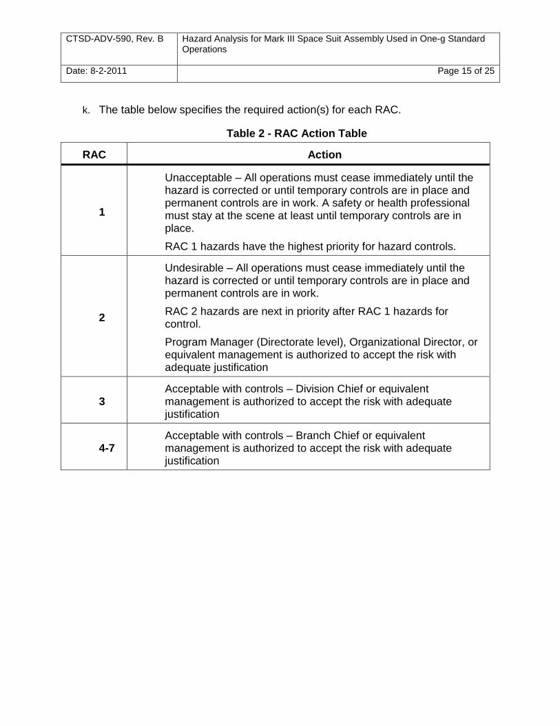
k. The table below specifies the required action(s) for each RAC.
Table 2 - RAC Action Table
RAC Action
1
Unacceptable – All operations must cease immediately until the hazard is corrected or until temporary controls are in place and permanent controls are in work. A safety or health professional must stay at the scene at least until temporary controls are in place.
RAC 1 hazards have the highest priority for hazard controls.
2
Undesirable – All operations must cease immediately until the hazard is corrected or until temporary controls are in place and permanent controls are in work.
RAC 2 hazards are next in priority after RAC 1 hazards for control.
Program Manager (Directorate level), Organizational Director, or equivalent management is authorized to accept the risk with adequate justification
3 Acceptable with controls – Division Chief or equivalent management is authorized to accept the risk with adequate justification
4-7 Acceptable with controls – Branch Chief or equivalent management is authorized to accept the risk with adequate justification
CTSD-ADV-590, Rev. B Hazard Analysis for Mark III Space Suit Assembly Used in One-g Standard Operations
Date: 8-2-2011 Page 16 of 25
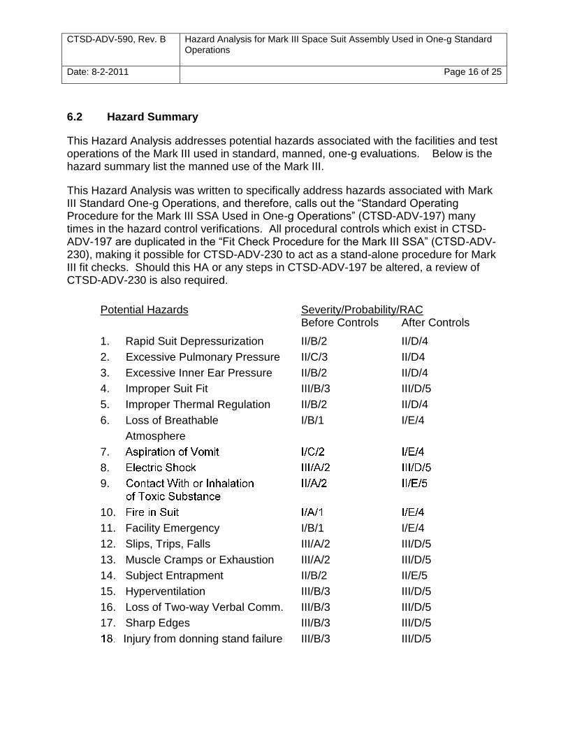
6.2 Hazard Summary
This Hazard Analysis addresses potential hazards associated with the facilities and test operations of the Mark III used in standard, manned, one-g evaluations. Below is the hazard summary list the manned use of the Mark III.
This Hazard Analysis was written to specifically address hazards associated with Mark III Standard One-g Operations, and therefore, calls out the ―Standard Operating Procedure for the Mark III SSA Used in One-g Operations‖ (CTSD-ADV-197) many times in the hazard control verifications. All procedural controls which exist in CTSD-ADV-197 are duplicated in the ―Fit Check Procedure for the Mark III SSA‖ (CTSD-ADV-230), making it possible for CTSD-ADV-230 to act as a stand-alone procedure for Mark III fit checks. Should this HA or any steps in CTSD-ADV-197 be altered, a review of CTSD-ADV-230 is also required.
Potential Hazards Severity/Probability/RAC Before Controls After Controls
1. Rapid Suit Depressurization II/B/2 II/D/4
2. Excessive Pulmonary Pressure II/C/3 II/D4
3. Excessive Inner Ear Pressure II/B/2 II/D/4
4. Improper Suit Fit III/B/3 III/D/5
5. Improper Thermal Regulation II/B/2 II/D/4
6. Loss of Breathable I/B/1 I/E/4
Atmosphere
7.
8.
9.
10.
11. Facility Emergency I/B/1 I/E/4
12. Slips, Trips, Falls III/A/2 III/D/5
13. Muscle Cramps or Exhaustion III/A/2 III/D/5
14. Subject Entrapment II/B/2 II/E/5
15. Hyperventilation III/B/3 III/D/5
16. Loss of Two-way Verbal Comm. III/B/3 III/D/5
17. Sharp Edges III/B/3 III/D/5
Injury from donning stand failure III/B/3 III/D/5
CTSD-ADV-590, Rev. B Hazard Analysis for Mark III Space Suit Assembly Used in One-g Standard Operations
Date: 8-2-2011 Page 17 of 25
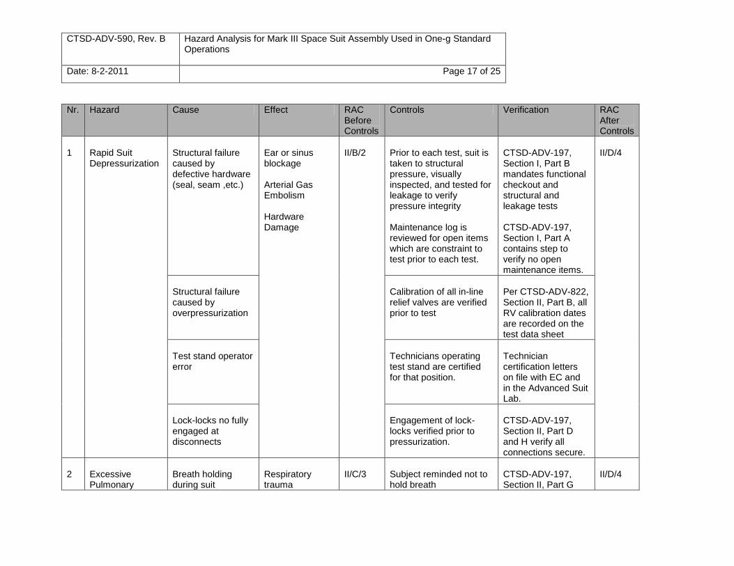
Nr. Hazard Cause Effect RAC Before Controls
Controls Verification RAC After Controls
1
Rapid Suit Depressurization
Structural failure caused by defective hardware (seal, seam ,etc.)
Ear or sinus blockage Arterial Gas Embolism Hardware Damage
II/B/2
Prior to each test, suit is taken to structural pressure, visually inspected, and tested for leakage to verify pressure integrity Maintenance log is reviewed for open items which are constraint to test prior to each test.
CTSD-ADV-197, Section I, Part B mandates functional checkout and structural and leakage tests CTSD-ADV-197, Section I, Part A contains step to verify no open maintenance items.
II/D/4
Structural failure caused by overpressurization
Calibration of all in-line relief valves are verified prior to test
Per CTSD-ADV-822, Section II, Part B, all RV calibration dates are recorded on the test data sheet
Test stand operator error
Technicians operating test stand are certified for that position.
Technician certification letters on file with EC and in the Advanced Suit Lab.
Lock-locks no fully engaged at disconnects
Engagement of lock-locks verified prior to pressurization.
CTSD-ADV-197, Section II, Part D and H verify all connections secure.
2
Excessive Pulmonary
Breath holding during suit
Respiratory trauma
II/C/3
Subject reminded not to hold breath
CTSD-ADV-197, Section II, Part G
II/D/4

CTSD-ADV-590, Rev. B Hazard Analysis for Mark III Space Suit Assembly Used in One-g Standard Operations
Date: 8-2-2011 Page 18 of 25
Nr. Hazard Cause Effect RAC Before Controls
Controls Verification RAC After Controls
Pressure depressurization outlines test subject safety brief
3
Excessive Inner Ear Pressure
Inappropriate (too little or excessive) use of Valsalva maneuver
Ear trauma, loss of equilibrium
II/B/2
Test subject is briefed on barotraumas and excessive use of Valsalva associated with suit test
CTSD-ADV-197, Section II, Part G outlines test subject safety brief
II/D/4
4
Improper Suit Fit
Use of improperly sized equipment
Discomfort Reduced mobility Bruising, abrasion
III/B/3
Test subjects are required to have a successful fit-check prior to test participation
Mark III Use Log requires date of fit-check to be recorded prior to test
III/D/5
Individual sizing records are used to build up suits prior to test
CTSD-ADV-197, Section I, Part A verifies suit is sized according to record
Certified suit engineers have been trained in sizing philosophy.
Suit Engineer Certifications on file in EC and B34
5
Improper Thermal Regulation
Failure of cooling unit
Test subject discomfort Reduced capacity to work
II/B/2
Function of cooling unit verified prior to test
CTSD-ADV-197, Section II, Part E verifies function of cooling system
II/D/4
Failure of cooling garment lines
LCG leak checked prior to test
CTSD-ADV-862, Section II, Part H verifies no leaks after connecting cooling system to
CTSD-ADV-590, Rev. B Hazard Analysis for Mark III Space Suit Assembly Used in One-g Standard Operations
Date: 8-2-2011 Page 19 of 25
Nr. Hazard Cause Effect RAC Before Controls
Controls Verification RAC After Controls
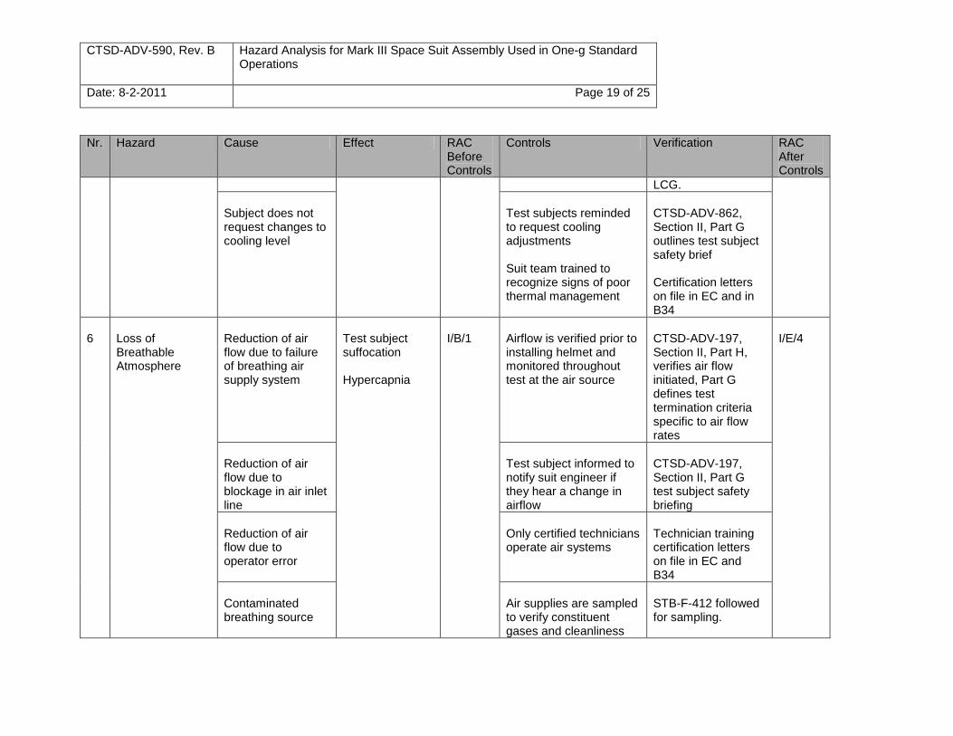
LCG.
Subject does not request changes to cooling level
Test subjects reminded to request cooling adjustments Suit team trained to recognize signs of poor thermal management
CTSD-ADV-862, Section II, Part G outlines test subject safety brief Certification letters on file in EC and in B34
6
Loss of Breathable Atmosphere
Reduction of air flow due to failure of breathing air supply system
Test subject suffocation Hypercapnia
I/B/1
Airflow is verified prior to installing helmet and monitored throughout test at the air source
CTSD-ADV-197, Section II, Part H, verifies air flow initiated, Part G defines test termination criteria specific to air flow rates
I/E/4
Reduction of air flow due to blockage in air inlet line
Test subject informed to notify suit engineer if they hear a change in airflow
CTSD-ADV-197, Section II, Part G test subject safety briefing
Reduction of air flow due to operator error
Only certified technicians operate air systems
Technician training certification letters on file in EC and B34
Contaminated breathing source
Air supplies are sampled to verify constituent gases and cleanliness
STB-F-412 followed for sampling.
CTSD-ADV-590, Rev. B Hazard Analysis for Mark III Space Suit Assembly Used in One-g Standard Operations
Date: 8-2-2011 Page 20 of 25
Nr. Hazard Cause Effect RAC Before Controls
Controls Verification RAC After Controls
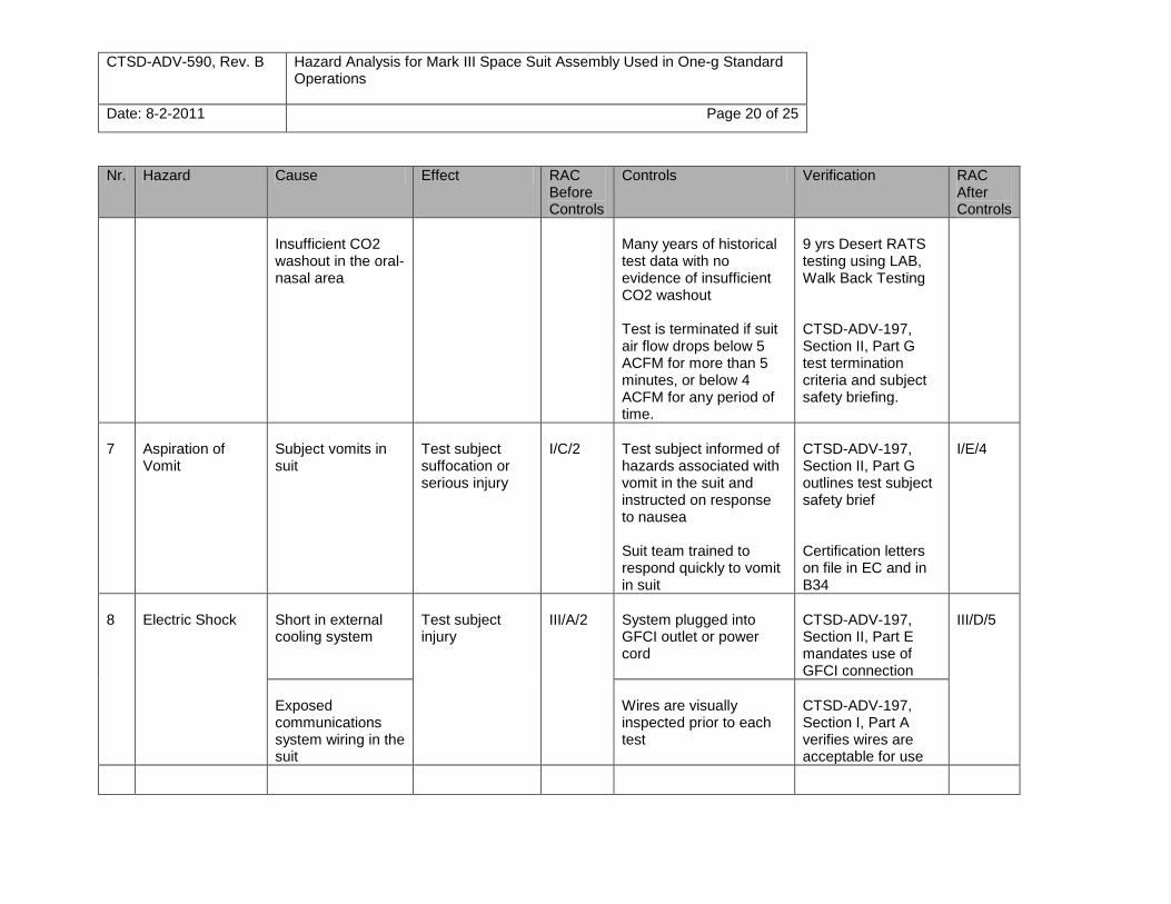
Insufficient CO2 washout in the oral-nasal area
Many years of historical test data with no evidence of insufficient CO2 washout Test is terminated if suit air flow drops below 5 ACFM for more than 5 minutes, or below 4 ACFM for any period of time.
9 yrs Desert RATS testing using LAB, Walk Back Testing CTSD-ADV-197, Section II, Part G test termination criteria and subject safety briefing.
7
Aspiration of Vomit
Subject vomits in suit
Test subject suffocation or serious injury
I/C/2
Test subject informed of hazards associated with vomit in the suit and instructed on response to nausea Suit team trained to respond quickly to vomit in suit
CTSD-ADV-197, Section II, Part G outlines test subject safety brief Certification letters on file in EC and in B34
I/E/4
8
Electric Shock
Short in external cooling system
Test subject injury
III/A/2
System plugged into GFCI outlet or power cord
CTSD-ADV-197, Section II, Part E mandates use of GFCI connection
III/D/5
Exposed communications system wiring in the suit
Wires are visually inspected prior to each test
CTSD-ADV-197, Section I, Part A verifies wires are acceptable for use
CTSD-ADV-590, Rev. B Hazard Analysis for Mark III Space Suit Assembly Used in One-g Standard Operations
Date: 8-2-2011 Page 21 of 25
Nr. Hazard Cause Effect RAC Before Controls
Controls Verification RAC After Controls
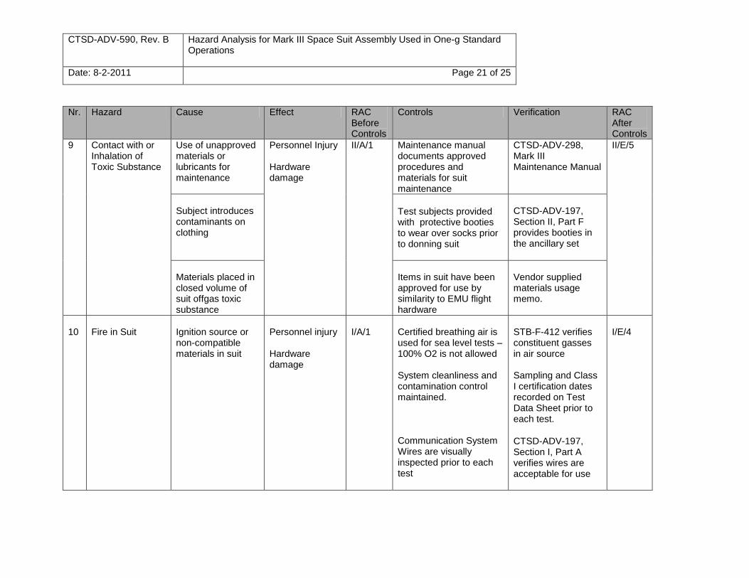
9
Contact with or Inhalation of Toxic Substance
Use of unapproved materials or lubricants for maintenance
Personnel Injury Hardware damage
II/A/1 Maintenance manual documents approved procedures and materials for suit maintenance
CTSD-ADV-298, Mark III Maintenance Manual
II/E/5
Subject introduces contaminants on clothing
Test subjects provided with protective booties to wear over socks prior to donning suit
CTSD-ADV-197, Section II, Part F provides booties in the ancillary set
Materials placed in closed volume of suit offgas toxic substance
Items in suit have been approved for use by similarity to EMU flight hardware
Vendor supplied materials usage memo.
10
Fire in Suit
Ignition source or non-compatible materials in suit
Personnel injury Hardware damage
I/A/1
Certified breathing air is used for sea level tests – 100% O2 is not allowed System cleanliness and contamination control maintained. Communication System Wires are visually inspected prior to each test
STB-F-412 verifies constituent gasses in air source Sampling and Class I certification dates recorded on Test Data Sheet prior to each test.
CTSD-ADV-197, Section I, Part A verifies wires are acceptable for use
I/E/4
CTSD-ADV-590, Rev. B Hazard Analysis for Mark III Space Suit Assembly Used in One-g Standard Operations
Date: 8-2-2011 Page 22 of 25
Nr. Hazard Cause Effect RAC Before Controls
Controls Verification RAC After Controls
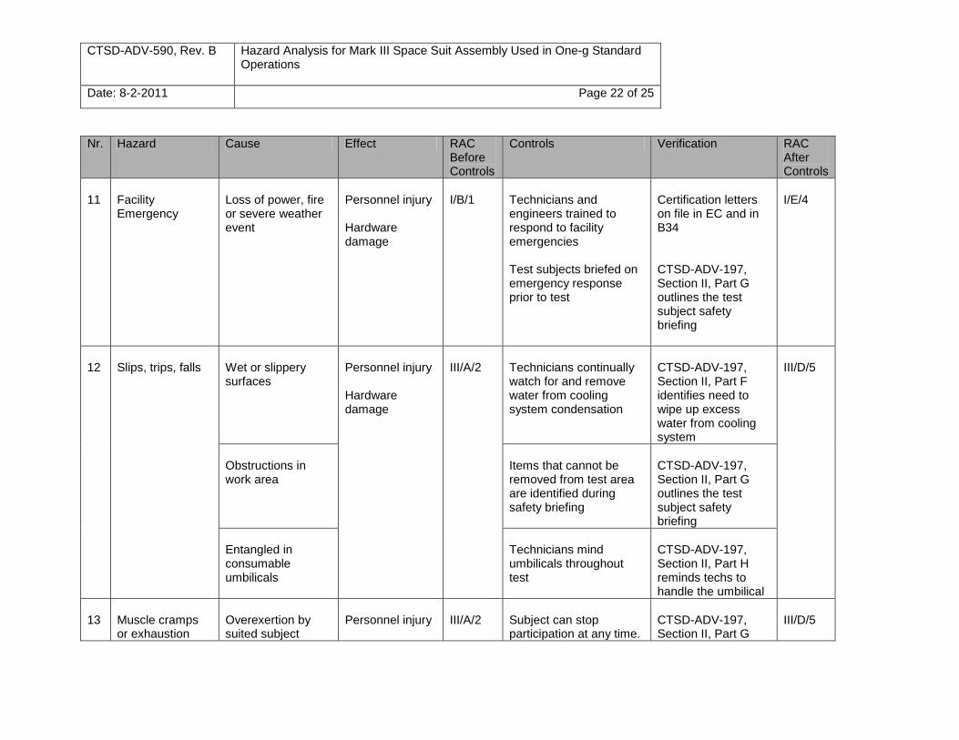
11
Facility Emergency
Loss of power, fire or severe weather event
Personnel injury Hardware damage
I/B/1
Technicians and engineers trained to respond to facility emergencies Test subjects briefed on emergency response prior to test
Certification letters on file in EC and in B34 CTSD-ADV-197, Section II, Part G outlines the test subject safety briefing
I/E/4
12
Slips, trips, falls
Wet or slippery surfaces
Personnel injury Hardware damage
III/A/2
Technicians continually watch for and remove water from cooling system condensation
CTSD-ADV-197, Section II, Part F identifies need to wipe up excess water from cooling system
III/D/5
Obstructions in work area
Items that cannot be removed from test area are identified during safety briefing
CTSD-ADV-197, Section II, Part G outlines the test subject safety briefing
Entangled in consumable umbilicals
Technicians mind umbilicals throughout test
CTSD-ADV-197, Section II, Part H reminds techs to handle the umbilical
13
Muscle cramps or exhaustion
Overexertion by suited subject
Personnel injury
III/A/2
Subject can stop participation at any time.
CTSD-ADV-197, Section II, Part G
III/D/5
CTSD-ADV-590, Rev. B Hazard Analysis for Mark III Space Suit Assembly Used in One-g Standard Operations
Date: 8-2-2011 Page 23 of 25
Nr. Hazard Cause Effect RAC Before Controls
Controls Verification RAC After Controls
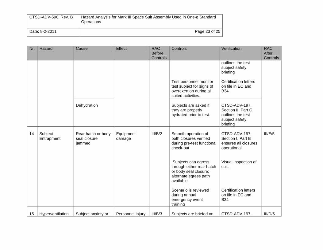
Test personnel monitor test subject for signs of overexertion during all suited activities.
outlines the test subject safety briefing Certification letters on file in EC and B34
Dehydration
Subjects are asked if they are properly hydrated prior to test.
CTSD-ADV-197, Section II, Part G outlines the test subject safety briefing
14
Subject Entrapment
Rear hatch or body seal closure jammed
Equipment damage
III/B/2
Smooth operation of both closures verified during pre-test functional check-out Subjects can egress through either rear hatch or body seal closure; alternate egress path available. Scenario is reviewed during annual emergency event training
CTSD-ADV-197, Section I, Part B ensures all closures operational Visual inspection of suit. Certification letters on file in EC and B34
III/E/5
15
Hyperventilation
Subject anxiety or
Personnel injury
III/B/3
Subjects are briefed on
CTSD-ADV-197,
III/D/5
CTSD-ADV-590, Rev. B Hazard Analysis for Mark III Space Suit Assembly Used in One-g Standard Operations
Date: 8-2-2011 Page 24 of 25
Nr. Hazard Cause Effect RAC Before Controls
Controls Verification RAC After Controls
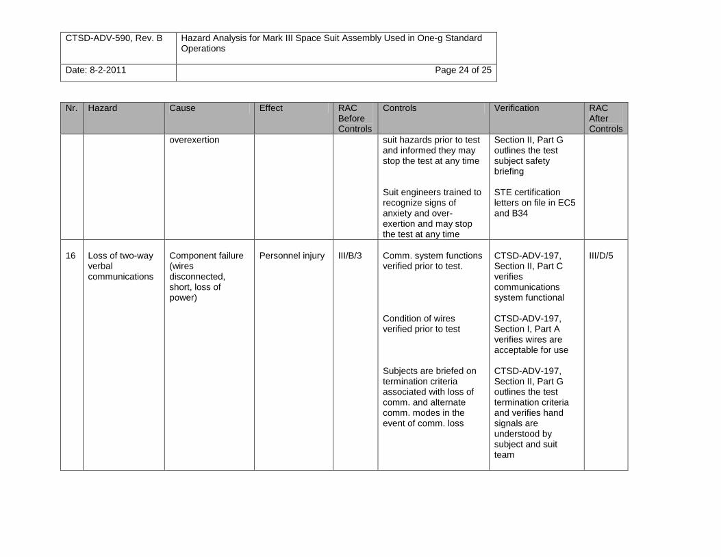
overexertion suit hazards prior to test and informed they may stop the test at any time Suit engineers trained to recognize signs of anxiety and over-exertion and may stop the test at any time
Section II, Part G outlines the test subject safety briefing STE certification letters on file in EC5 and B34
16
Loss of two-way verbal communications
Component failure (wires disconnected, short, loss of power)
Personnel injury
III/B/3
Comm. system functions verified prior to test. Condition of wires verified prior to test Subjects are briefed on termination criteria associated with loss of comm. and alternate comm. modes in the event of comm. loss
CTSD-ADV-197, Section II, Part C verifies communications system functional CTSD-ADV-197, Section I, Part A verifies wires are acceptable for use CTSD-ADV-197, Section II, Part G outlines the test termination criteria and verifies hand signals are understood by subject and suit team
III/D/5

CTSD-ADV-590, Rev. B Hazard Analysis for Mark III Space Suit Assembly Used in One-g Standard Operations
Date: 8-2-2011 Page 25 of 25
Nr. Hazard Cause Effect RAC Before Controls
Controls Verification RAC After Controls
Improper SPACIS configuration
Suit team trained to operate SPACIS
Engineer and tech certification letters on file in EC and B34 Configuration cheat sheet posted on SPACIS stand.
17
Sharp Edges or Protrusions
Worn hardware from use and maintenance
Personnel injury
III/B/3
Suit hardware is inspected prior to use to verify assemblies are free of sharp edges. Any worn screws or potentially sharp edges are repaired or replaced prior to use.
Maintenance log is reviewed for open items which are constraint to test prior to each test.
CTSD-ADV-197, Section 1, Part A and Section II, Part F inspect for sharp edges prior to test.
CTSD-ADV-197, Section I, Part A contains step to verify no open maintenance items.
III/D/5
18
Injury from donning stand
Donning stand failure
Personnel injury
III/B/3
Donning stand and stairs are load certified annually.
Load certification tag on donning stand.
III/D/5


