
CSCI-1680 Link Layer Wrap-Up
Based partly on lecture notes by David Mazières, Phil Levis, John Janno<
Rodrigo Fonseca

Administrivia
• Homework I out later today, due next Friday, Feb 17th
Today: Link Layer (cont.)
• Framing • Reliability – Error correction – Sliding window
• Medium Access Control • Case study: Ethernet • Link Layer Switching
Media Access Control
• Control access to shared physical medium – E.g., who can talk when? – If everyone talks at once, no one hears anything – Job of the Link Layer
• Two con!icting goals – Maximize utilization when one node sending – Approach 1/N allocation when N nodes sending

Different Approaches
• Partitioned Access – Time Division Multiple Access (TDMA) – Frequency Division Multiple Access (FDMA) – Code Division Multiple Access (CDMA)
• Random Access – ALOHA/ Slotted ALOHA – Carrier Sense Multiple Access / Collision Detection
(CSMA/CD) – Carrier Sense Multiple Access / Collision Avoidance
(CSMA/CA) – RTS/CTS (Request to Send/Clear to Send) – Token-based
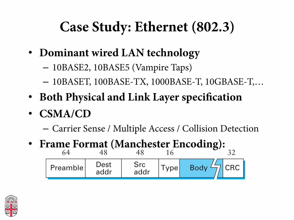
Case Study: Ethernet (802.3)
• Dominant wired LAN technology – 10BASE2, 10BASE5 (Vampire Taps) – 10BASET, 100BASE-TX, 1000BASE-T, 10GBASE-T,…
• Both Physical and Link Layer speci#cation • CSMA/CD
– Carrier Sense / Multiple Access / Collision Detection • Frame Format (Manchester Encoding):
Destaddr
64 48 32
CRCPreamble Srcaddr
Type Body
1648

Ethernet Addressing
• Globally unique, 48-bit unicast address per adapter – Example: 00:1c:43:00:3d:09 (Samsung adapter) – 24 msb: organization – http://standards.ieee.org/develop/regauth/oui/oui.txt
• Broadcast address: all 1s • Multicast address: #rst bit 1 • Adapter can work in promiscuous mode

Ethernet MAC: CSMA/CD
• Problem: shared medium – 10Mbps: 2500m, with 4 repeaters at 500m
• Transmit algorithm – If line is idle, transmit immediately – Upper bound message size of 1500 bytes – Must wait 9.6μs (96-bit time) between back to back frames
• (Old limit) To give time to switch from tx to rx mode – If line is busy: wait until idle and transmit immediately

Handling Collisions
• Collision detection (10Base2 Ethernet) – Uses Manchester encoding. Why does that help? – Constant average voltage unless multiple transmitters
• If collision – Jam for 32 bits, then stop transmitting frame
• Collision detection constrains protocol – Imposes min. packet size (64 bytes or 512 bits) – Imposes maximum network diameter (2500m) – Ensure transmission time ≥ 2x propagation delay
(why?)
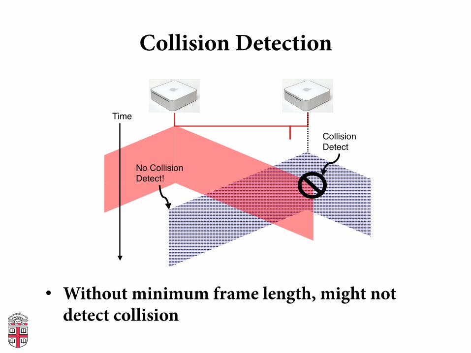
Collision Detection
• Without minimum frame length, might not detect collision
Violating Timing Constraints
Time
Collision
Detect
No Collision
Detect!
• Without min packet size, might miss collision

When to transmit again?
• Delay and try again: exponential backoff • nth time: k × 51.2μs, for k = U{0..2min(n,10)-1}
– 1st time: 0 or 51.2μs – 2nd time: 0, 51.2, 102.4, or 153.6μs
• Give up aer several times (usually 16)

Capture Effect
• Exponential backoff leads to self-adaptive use of channel
• A and B are trying to transmit, and collide • Both will back off either 0 or 51.2μs • Say A wins. • Next time, collide again.
– A will wait between 0 or 1 slots – B will wait between 0, 1, 2, or 3 slots
• …
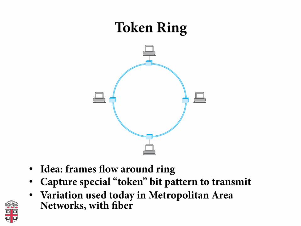
Token Ring
• Idea: frames !ow around ring • Capture special “token” bit pattern to transmit • Variation used today in Metropolitan Area
Networks, with #ber

Interface Cards
• Problem: if host dies, can break the network • Hardware typically has relays
Host
From previoushost
To nexthost
Relay
(a)
Host
Host Host
From previoushost
To nexthost
Relay
(b)

Token Ring Frames
• Frame format (Differential Manchester)
• Sender grabs token, sends message(s) • Recipient checks address • Sender removes frame from ring aer lap • Maximum holding time: avoid capture • Monitor node reestablishes lost token
Body ChecksumSrcaddr
Variable48
Destaddr
48 32
Enddelimiter
8
Framestatus
8
Framecontrol
8
Accesscontrol
8
Startdelimiter
8
Switching
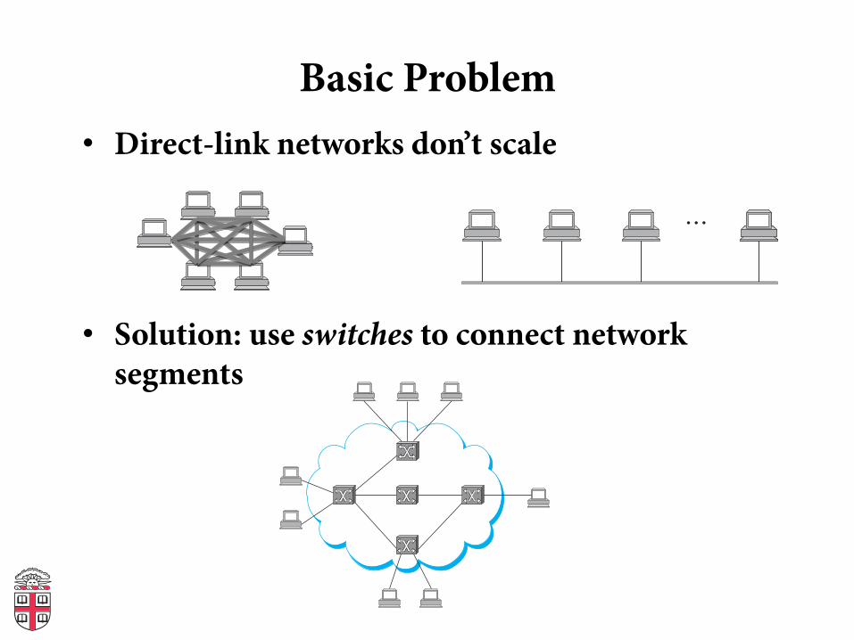
Basic Problem • Direct-link networks don’t scale
• Solution: use switches to connect network segments
(a)
(b)…
(a)
(b)…
(a)
(b)…
(a)
(b)…
(a)
(b)…
(a)
(b)…
(a)
(b)…
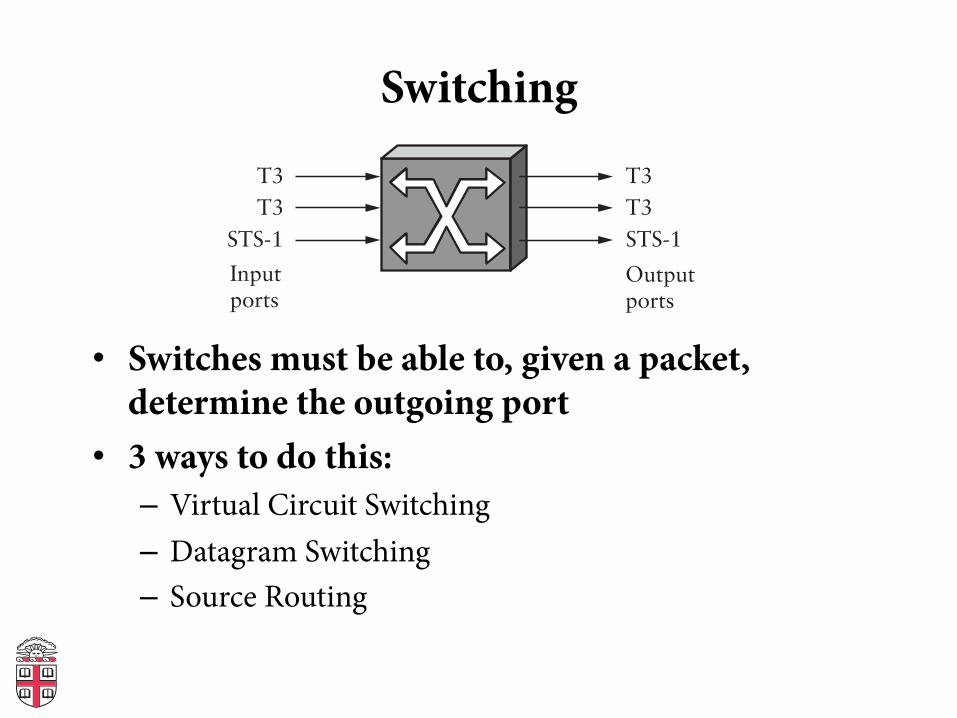
Switching
• Switches must be able to, given a packet, determine the outgoing port
• 3 ways to do this: – Virtual Circuit Switching – Datagram Switching – Source Routing
Inputports
T3
T3
STS-1
T3
T3
STS-1
Switch
Outputports
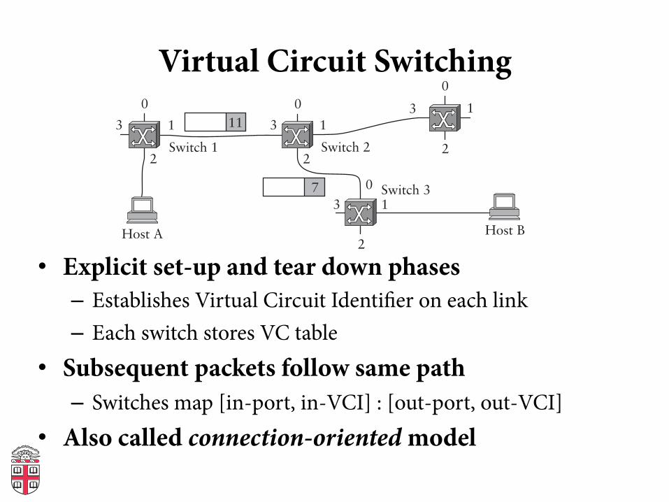
Virtual Circuit Switching
• Explicit set-up and tear down phases – Establishes Virtual Circuit Identi#er on each link – Each switch stores VC table
• Subsequent packets follow same path – Switches map [in-port, in-VCI] : [out-port, out-VCI]
• Also called connection-oriented model
0
1
2
3
0
1
2
3
0
1
2
3
0
1
2
3
Host A Host B
Switch 3
Switch 2Switch 1
7
11
Virtual Circuit Model
• Requires one RTT before sending #rst packet • Connection request contain full destination
address, subsequent packets only small VCI • Setup phase allows reservation of resources,
such as bandwidth or buffer-space – Any problems here?
• If a link or switch fails, must re-establish whole circuit
• Example: ATM
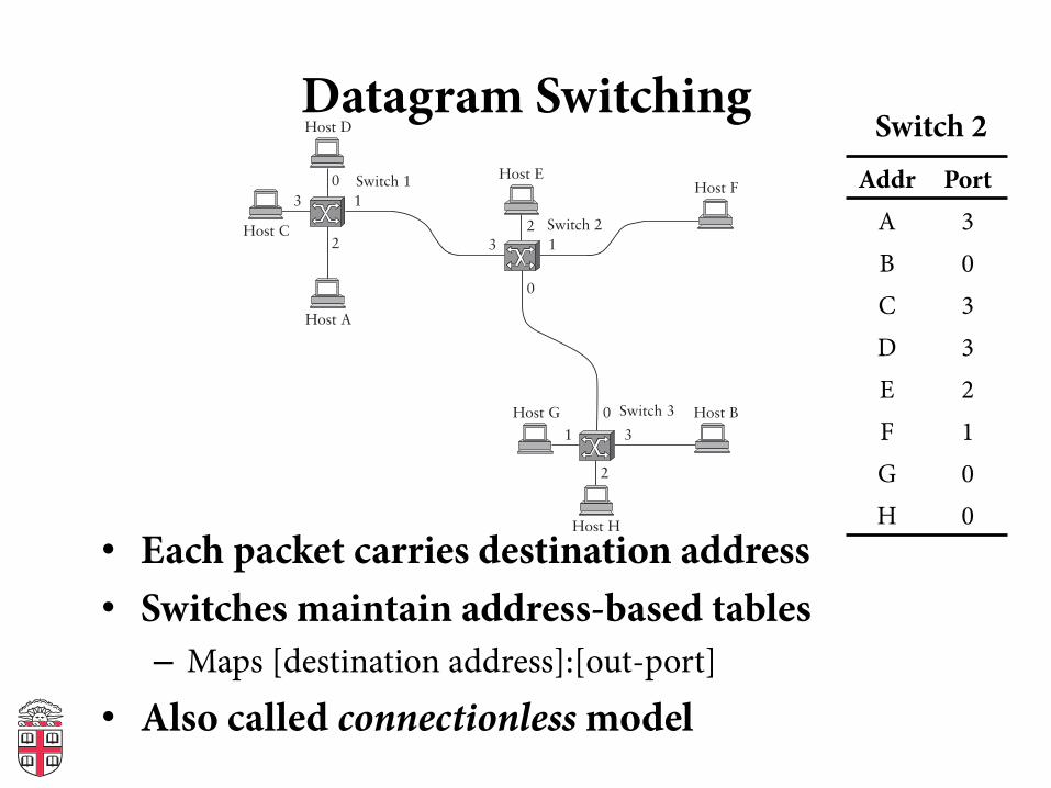
Datagram Switching
• Each packet carries destination address • Switches maintain address-based tables
– Maps [destination address]:[out-port]
• Also called connectionless model
0
132
01 3
2
013
2
Switch 3 Host B
Switch 2
Host A
Switch 1
Host C
Host D
Host EHost F
Host G
Host H
Addr Port A 3 B 0 C 3 D 3 E 2 F 1 G 0 H 0
Switch 2
Datagram Switching
• No delay for connection setup • Source can’t know if network can deliver a
packet • Possible to route around failures • Higher overhead per-packet • Potentially larger tables at switches
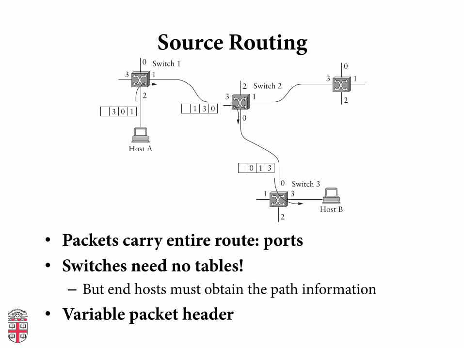
Source Routing
• Packets carry entire route: ports • Switches need no tables!
– But end hosts must obtain the path information • Variable packet header
0
132
01 3
2
0
13
2
0
13
23 0 1 3 01
30 1
Switch 3
Host B
Switch 2
Host A
Switch 1
Bridging

Bridges and Extended LANs
• LANs have limitations – E.g. Ethernet < 1024 hosts, < 2500m
• Connect two or more LANs with a bridge – Operates on Ethernet addresses – Forwards packets from one LAN to the other(s)
• Ethernet switch is just a multi-way bridge A
Bridge
B C
X Y Z
Port 1
Port 2
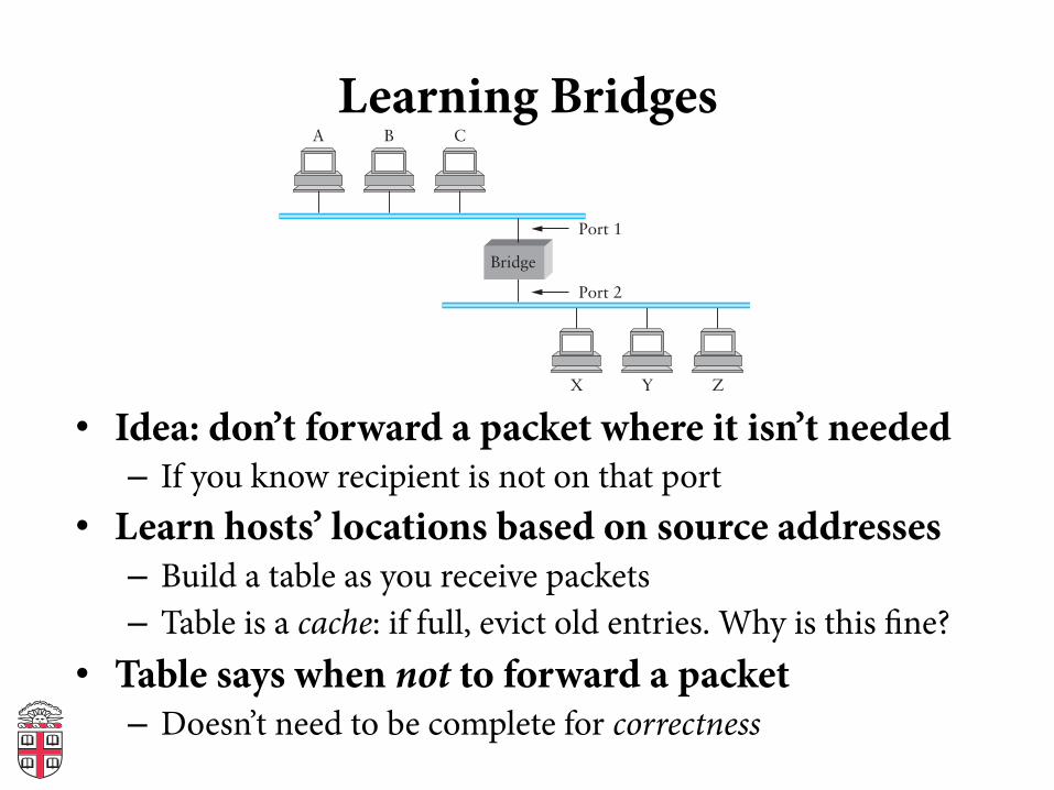
Learning Bridges
• Idea: don’t forward a packet where it isn’t needed – If you know recipient is not on that port
• Learn hosts’ locations based on source addresses – Build a table as you receive packets – Table is a cache: if full, evict old entries. Why is this #ne?
• Table says when not to forward a packet – Doesn’t need to be complete for correctness
A
Bridge
B C
X Y Z
Port 1
Port 2

Attack on a Learning Switch
• Eve: wants to sniff all packets sent to Bob • Same segment: easy (shared medium) • Different segment on a learning bridge: hard
– Once bridge learns Bob’s port, stop broadcasting • How can Eve force the bridge to keep
broadcasting? – Flood the network with frames with spoofed src addr!
Bridges
• Unicast: forward with #ltering • Broadcast: always forward • Multicast: always forward or learn groups • Difference between bridges and repeaters?
– Bridges: same broadcast domain; copy frames – Repeaters: same broadcast and collision domain; copy
signals

Dealing with Loops
• Problem: people may create loops in LAN! – Accidentally, or to provide redundancy – Don’t want to forward packets inde#nitely
A
C
E
D
B
K
F
H
J
G
I
B3
B7
B4
B2
B5
B1
B6
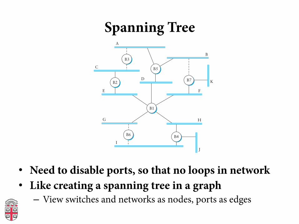
Spanning Tree
• Need to disable ports, so that no loops in network • Like creating a spanning tree in a graph – View switches and networks as nodes, ports as edges
A
C
E
D
B
K
F
H
J
G
I
B5
B2
B3
B7
B4
B1
B6
Distributed Spanning Tree Algorithm
• Every bridge has a unique ID (Ethernet address) • Goal: – Bridge with the smallest ID is the root – Each segment has one designated bridge, responsible for
forwarding its packets towards the root • Bridge closest to root is designated bridge • If there is a tie, bridge with lowest ID wins

Spanning Tree Protocol
• Spanning Tree messages contain: – ID of bridge sending the message – ID sender believes to be the root – Distance (in hops) from sender to root
• Bridges remember best con#g msg on each port • Send message when you think you are the root • Otherwise, forward messages from best known root – Add one to distance before forwarding – Don’t forward if you know you aren’t dedicated bridge
• In the end, only root is generating messages
Limitations of Bridges
• Scaling – Spanning tree algorithm doesn’t scale – Broadcast does not scale – No way to route around congested links, even if path
exists • May violate assumptions
– Could confuse some applications that assume single segment
– Much more likely to drop packets – Makes latency between nodes non-uniform – Beware of transparency

VLANs
• Company network, A and B departments – Broadcast traffic does not scale – May not want traffic between the two departments – Topology has to mirror physical locations – What if employees move between offices?
b1
b2
a1
a2
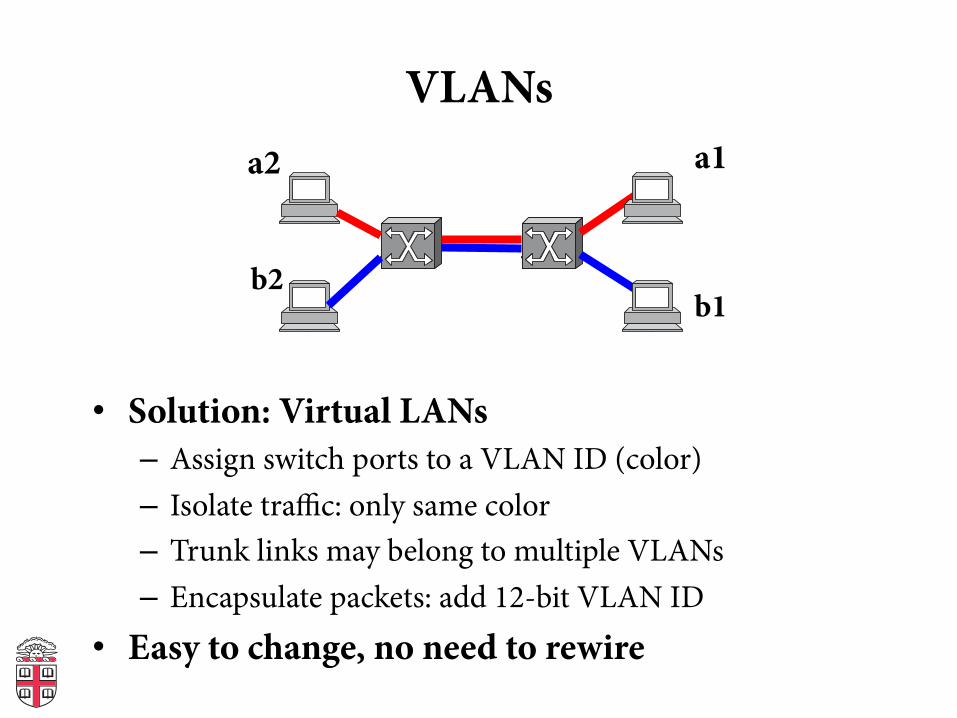
VLANs
• Solution: Virtual LANs – Assign switch ports to a VLAN ID (color) – Isolate traffic: only same color – Trunk links may belong to multiple VLANs – Encapsulate packets: add 12-bit VLAN ID
• Easy to change, no need to rewire
a2
b2
a1
b1
Generic Switch Architecture
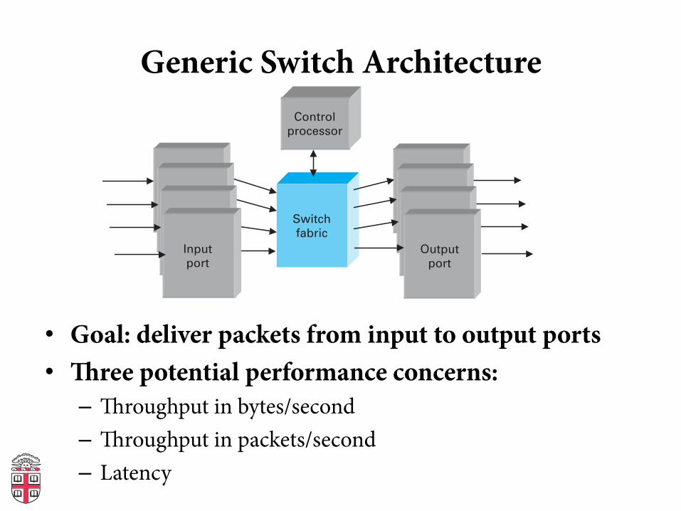
• Goal: deliver packets from input to output ports • ree potential performance concerns: – roughput in bytes/second – roughput in packets/second – Latency
Generic switch architecture
Switch fabric
Control processor
Output port
Input port
• Goal: deliver packets from input to output ports
• Three potential performance concerns:- Throughput in terms of bytes/time
- Throughput in terms of packets/time
- Latency
Cut through vs. Store and Forward
• Two approaches to forwarding a packet – Receive a full packet, then send to output port – Start retransmitting as soon as you know output port,
before full packet • Cut-through routing can greatly decrease latency • Disadvantage – Can waste transmission (classic optimistic approach) – CRC may be bad – If Ethernet collision, may have to send runt packet on
output link
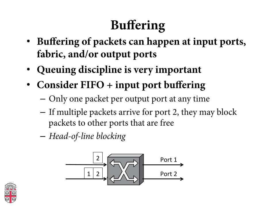
Buffering • Buffering of packets can happen at input ports,
fabric, and/or output ports • Queuing discipline is very important • Consider FIFO + input port buffering
– Only one packet per output port at any time – If multiple packets arrive for port 2, they may block
packets to other ports that are free – Head-of-line blocking
2
2 1
Port 1
Port 2
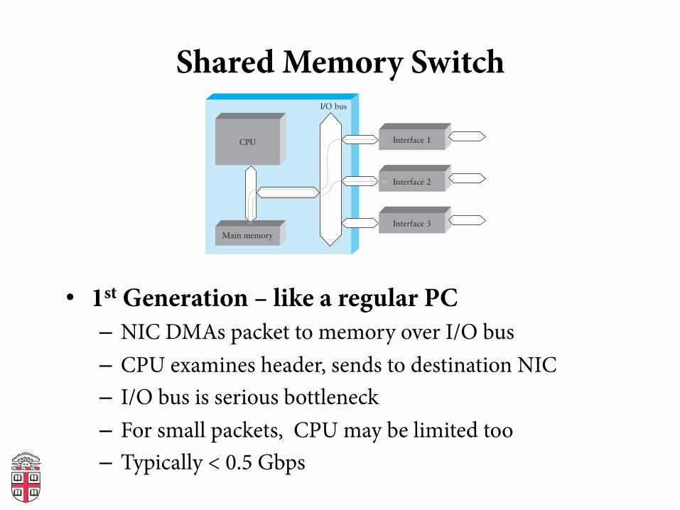
Shared Memory Switch
• 1st Generation – like a regular PC – NIC DMAs packet to memory over I/O bus – CPU examines header, sends to destination NIC – I/O bus is serious bottleneck – For small packets, CPU may be limited too – Typically < 0.5 Gbps
I/O bus
Interface 1
Interface 2
Interface 3
CPU
Main memory
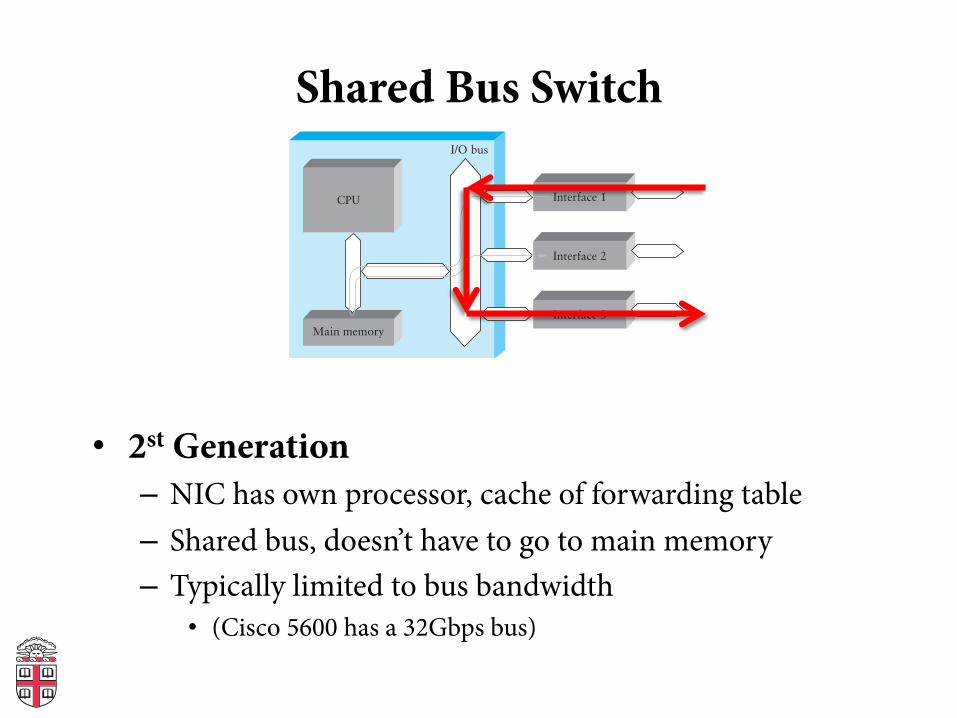
Shared Bus Switch
• 2st Generation – NIC has own processor, cache of forwarding table – Shared bus, doesn’t have to go to main memory – Typically limited to bus bandwidth
• (Cisco 5600 has a 32Gbps bus)
I/O bus
Interface 1
Interface 2
Interface 3
CPU
Main memory
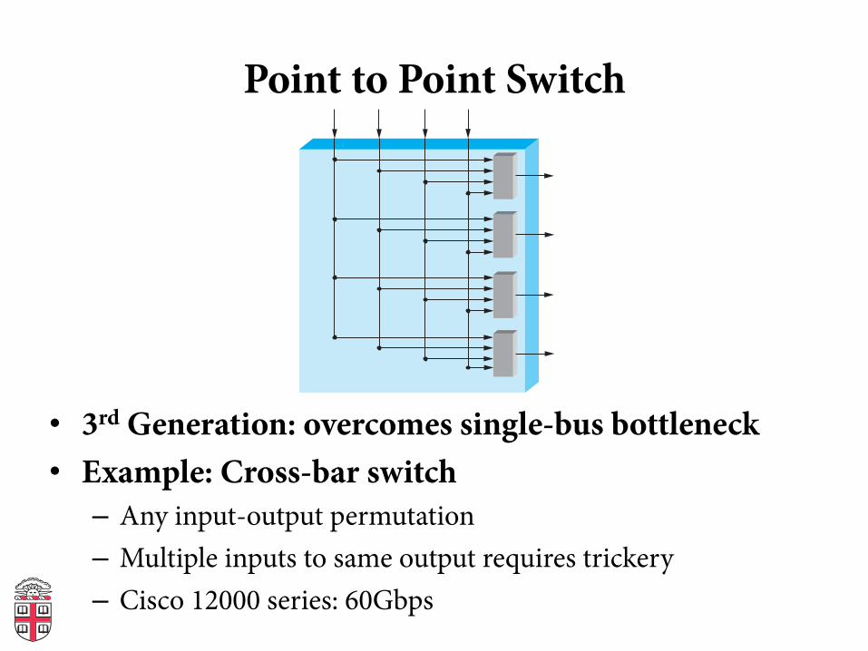
Point to Point Switch
• 3rd Generation: overcomes single-bus bottleneck • Example: Cross-bar switch – Any input-output permutation – Multiple inputs to same output requires trickery – Cisco 12000 series: 60Gbps

Coming Up
• Connecting multiple networks: IP and the Network Layer
• Remember: no class on Tuesday!


