Data Sheet 10/63-0.50 EN Rev. D
FOUNDATION fieldbus Installation suggestion
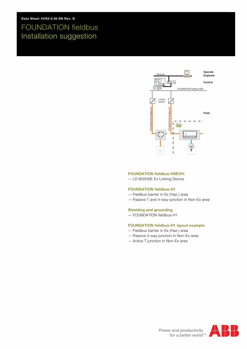
FOUNDATION fieldbus-HSE/H1 — LD 800HSE Ex Linking Device FOUNDATION fieldbus-H1 — Fieldbus barrier in Ex (Haz.) area — Passive T and 4-way-junction in Non-Ex area Shielding and grounding — FOUNDATION fieldbus-H1 FOUNDATION fieldbus-H1 layout example — Fieldbus barrier in Ex (Haz.) area — Passive 4-way junction in Non-Ex area — Active T junction in Non-Ex area
F
OperateEngineer
Control
Field
FOUNDATION fieldbus-HSE
Ethernet
LinkingDevice
FO
UN
DAT
ION
fiel
dbus
-H1
FO
UN
DAT
ION
fiel
dbus
-H1
FOUNDATION fieldbus - Installation suggestion
2
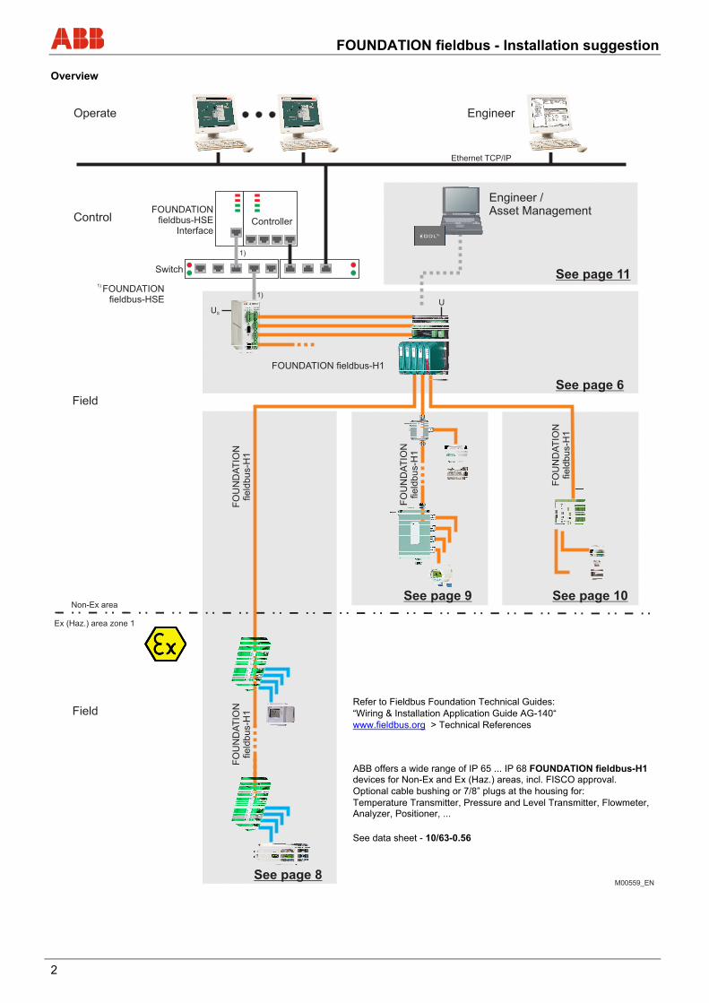
Overview
Refer to Fieldbus Foundation Technical Guides: “Wiring & Installation Application Guide AG-140“ www.fieldbus.org > Technical References
ABB offers a wide range of IP 65 ... IP 68 FOUNDATION fieldbus-H1 devices for Non-Ex and Ex (Haz.) areas, incl. FISCO approval. Optional cable bushing or 7/8” plugs at the housing for: Temperature Transmitter, Pressure and Level Transmitter, Flowmeter, Analyzer, Positioner, ...
See data sheet - 10/63-0.56
FOUNDATION fieldbus - Installation suggestion
3
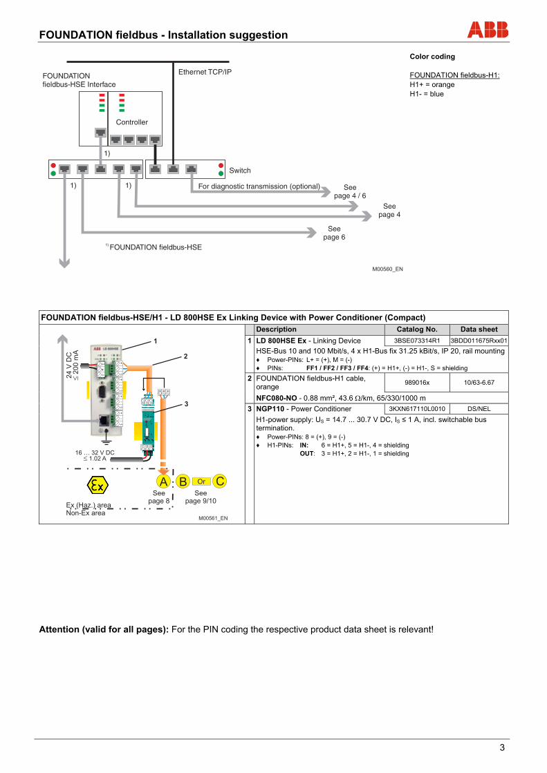
Color coding FOUNDATION fieldbus-H1: H1+ = orange H1- = blue
FOUNDATION fieldbus-HSE/H1 - LD 800HSE Ex Linking Device with Power Conditioner (Compact)
Description Catalog No. Data sheet
1 LD 800HSE Ex - Linking Device 3BSE073314R1 3BDD011675Rxx01
HSE-Bus 10 and 100 Mbit/s, 4 x H1-Bus fix 31.25 kBit/s, IP 20, rail mounting♦ Power-PINs: L+ = (+), M = (-) ♦ PINs: FF1 / FF2 / FF3 / FF4: (+) = H1+, (-) = H1-, S = shielding
2 FOUNDATION fieldbus-H1 cable, orange
989016x 10/63-6.67
NFC080-NO - 0.88 mm², 43.6 /km, 65/330/1000 m
3 NGP110 - Power Conditioner 3KXN617110L0010 DS/NEL
H1-power supply: US = 14.7 ... 30.7 V DC, IS ≤ 1 A, incl. switchable bus termination. ♦ Power-PINs: 8 = (+), 9 = (-) ♦ H1-PINs: IN: 6 = H1+, 5 = H1-, 4 = shielding OUT: 3 = H1+, 2 = H1-, 1 = shielding
Attention (valid for all pages): For the PIN coding the respective product data sheet is relevant!
Ethernet TCP/IPFOUNDATIONfieldbus-HSE Interface
Controller
Switch
1)
1) FOUNDATION fieldbus-HSE
1) 1)
Seepage 4
Seepage 6
M00560_EN
For diagnostic transmission (optional) Seepage 4 / 6
FOUNDATION fieldbus - Installation suggestion
4
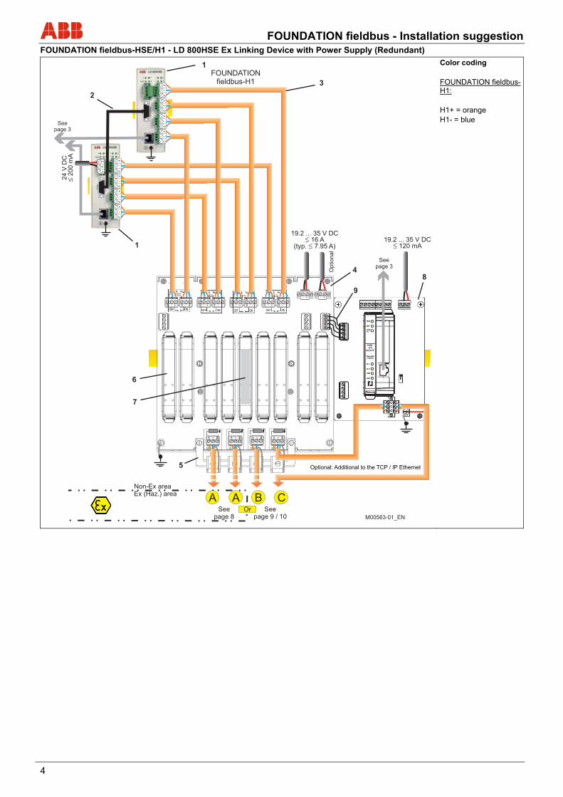
FOUNDATION fieldbus-HSE/H1 - LD 800HSE Ex Linking Device with Power Supply (Redundant)
Color coding FOUNDATION fieldbus-H1: H1+ = orange H1- = blue
SEG 1
+ - S
SEG 1
+ - S
SEG 1
+ - S
SEG 1
+ - S
5
4
6
7
A A B C
Optional
1
+
-
+
-
24
V D
C2
00
mA
L+
M
+
-
+
-
+
-
+
-
+
-
+
-
S - +S - +S - +S - +S - +S - +S - + S - +
- +- +
1
2
3
8
9
FOUNDATIONfieldbus-H1
Seepage 3
19.2 ... 35 V DC16 A
(typ. 7.95 A)
Non-Ex areaEx (Haz.) area
Seepage 8
Seepage 9 / 10
Or
19.2 ... 35 V DC120 mA
Seepage 3
Optional: Additional to the TCP / IP Ethernet
M00563-01_EN
FOUNDATION fieldbus - Installation suggestion
5
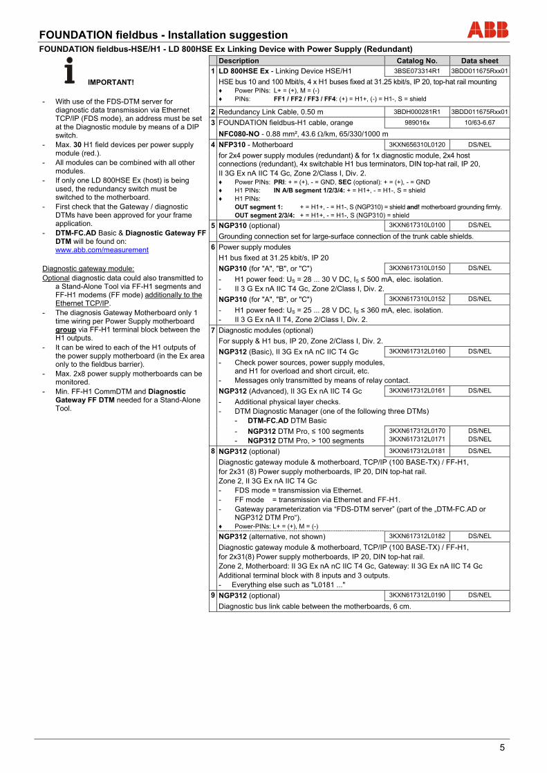
FOUNDATION fieldbus-HSE/H1 - LD 800HSE Ex Linking Device with Power Supply (Redundant)
IMPORTANT!
Description Catalog No. Data sheet
1 LD 800HSE Ex - Linking Device HSE/H1 3BSE073314R1 3BDD011675Rxx01
HSE bus 10 and 100 Mbit/s, 4 x H1 buses fixed at 31.25 kbit/s, IP 20, top-hat rail mounting ♦ Power PINs: L+ = (+), M = (-) ♦ PINs: FF1 / FF2 / FF3 / FF4: (+) = H1+, (-) = H1-, S = shield - With use of the FDS-DTM server for
diagnostic data transmission via Ethernet TCP/IP (FDS mode), an address must be set at the Diagnostic module by means of a DIP switch.
- Max. 30 H1 field devices per power supply module (red.).
- All modules can be combined with all other modules.
- If only one LD 800HSE Ex (host) is being used, the redundancy switch must be switched to the motherboard.
- First check that the Gateway / diagnostic DTMs have been approved for your frame application.
- DTM-FC.AD Basic & Diagnostic Gateway FF DTM will be found on: www.abb.com/measurement
Diagnostic gateway module: Optional diagnostic data could also transmitted to
a Stand-Alone Tool via FF-H1 segments and FF-H1 modems (FF mode) additionally to the Ethernet TCP/IP.
- The diagnosis Gateway Motherboard only 1 time wiring per Power Supply motherboard group via FF-H1 terminal block between the H1 outputs.
- It can be wired to each of the H1 outputs of the power supply motherboard (in the Ex area only to the fieldbus barrier).
- Max. 2x8 power supply motherboards can be monitored.
- Min. FF-H1 CommDTM and Diagnostic Gateway FF DTM needed for a Stand-Alone Tool.
2 Redundancy Link Cable, 0.50 m 3BDH000281R1 3BDD011675Rxx01
3 FOUNDATION fieldbus-H1 cable, orange 989016x 10/63-6.67
NFC080-NO - 0.88 mm², 43.6 /km, 65/330/1000 m
4 NFP310 - Motherboard 3KXN656310L0120 DS/NEL
for 2x4 power supply modules (redundant) & for 1x diagnostic module, 2x4 host connections (redundant), 4x switchable H1 bus terminators, DIN top-hat rail, IP 20, II 3G Ex nA IIC T4 Gc, Zone 2/Class I, Div. 2. ♦ Power PINs: PRI: + = (+), - = GND, SEC (optional): + = (+), - = GND ♦ H1 PINs: IN A/B segment 1/2/3/4: + = H1+, - = H1-, S = shield ♦ H1 PINs: OUT segment 1: + = H1+, - = H1-, S (NGP310) = shield and! motherboard grounding firmly. OUT segment 2/3/4: + = H1+, - = H1-, S (NGP310) = shield
5 NGP310 (optional) 3KXN617310L0100 DS/NEL
Grounding connection set for large-surface connection of the trunk cable shields.
6 Power supply modules
H1 bus fixed at 31.25 kbit/s, IP 20
NGP310 (for "A", "B", or "C") 3KXN617310L0150 DS/NEL
- H1 power feed: US = 28 ... 30 V DC, IS ≤ 500 mA, elec. isolation. - II 3 G Ex nA IIC T4 Gc, Zone 2/Class I, Div. 2.
NGP310 (for "A", "B", or "C") 3KXN617310L0152 DS/NEL
- H1 power feed: US = 25 ... 28 V DC, IS ≤ 360 mA, elec. isolation. - II 3 G Ex nA II T4, Zone 2/Class I, Div. 2.
7 Diagnostic modules (optional)
For supply & H1 bus, IP 20, Zone 2/Class I, Div. 2.
NGP312 (Basic), II 3G Ex nA nC IIC T4 Gc 3KXN617312L0160 DS/NEL
- Check power sources, power supply modules, and H1 for overload and short circuit, etc.
- Messages only transmitted by means of relay contact.
NGP312 (Advanced), II 3G Ex nA IIC T4 Gc 3KXN617312L0161 DS/NEL
- Additional physical layer checks. - DTM Diagnostic Manager (one of the following three DTMs) - DTM-FC.AD DTM Basic
- NGP312 DTM Pro, ≤ 100 segments - NGP312 DTM Pro, > 100 segments
3KXN617312L0170 3KXN617312L0171
DS/NEL DS/NEL
8 NGP312 (optional) 3KXN617312L0181 DS/NEL
Diagnostic gateway module & motherboard, TCP/IP (100 BASE-TX) / FF-H1, for 2x31 (8) Power supply motherboards, IP 20, DIN top-hat rail. Zone 2, II 3G Ex nA IIC T4 Gc
- FDS mode = transmission via Ethernet. - FF mode = transmission via Ethernet and FF-H1. - Gateway parameterization via “FDS-DTM server” (part of the „DTM-FC.AD or
NGP312 DTM Pro“). ♦ Power-PINs: L+ = (+), M = (-)
NGP312 (alternative, not shown) 3KXN617312L0182 DS/NEL
Diagnostic gateway module & motherboard, TCP/IP (100 BASE-TX) / FF-H1, for 2x31(8) Power supply motherboards, IP 20, DIN top-hat rail. Zone 2, Motherboard: II 3G Ex nA nC IIC T4 Gc, Gateway: II 3G Ex nA IIC T4 Gc Additional terminal block with 8 inputs and 3 outputs. - Everything else such as "L0181 ..."
9 NGP312 (optional) 3KXN617312L0190 DS/NEL
Diagnostic bus link cable between the motherboards, 6 cm.
FOUNDATION fieldbus - Installation suggestion
6
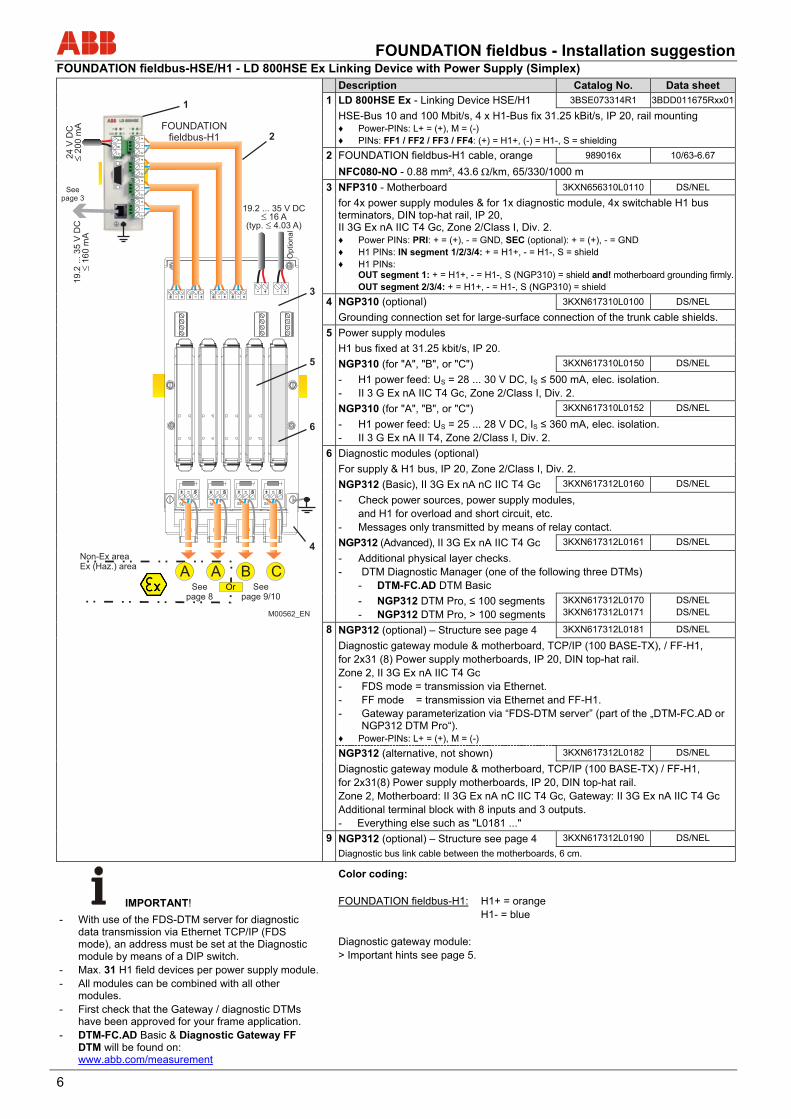
FOUNDATION fieldbus-HSE/H1 - LD 800HSE Ex Linking Device with Power Supply (Simplex) Description Catalog No. Data sheet
1 LD 800HSE Ex - Linking Device HSE/H1 3BSE073314R1 3BDD011675Rxx01
HSE-Bus 10 and 100 Mbit/s, 4 x H1-Bus fix 31.25 kBit/s, IP 20, rail mounting ♦ Power-PINs: L+ = (+), M = (-) ♦ PINs: FF1 / FF2 / FF3 / FF4: (+) = H1+, (-) = H1-, S = shielding
2 FOUNDATION fieldbus-H1 cable, orange 989016x 10/63-6.67
NFC080-NO - 0.88 mm², 43.6 /km, 65/330/1000 m
3 NFP310 - Motherboard 3KXN656310L0110 DS/NEL
for 4x power supply modules & for 1x diagnostic module, 4x switchable H1 bus terminators, DIN top-hat rail, IP 20, II 3G Ex nA IIC T4 Gc, Zone 2/Class I, Div. 2. ♦ Power PINs: PRI: + = (+), - = GND, SEC (optional): + = (+), - = GND ♦ H1 PINs: IN segment 1/2/3/4: + = H1+, - = H1-, S = shield ♦ H1 PINs: OUT segment 1: + = H1+, - = H1-, S (NGP310) = shield and! motherboard grounding firmly. OUT segment 2/3/4: + = H1+, - = H1-, S (NGP310) = shield
4 NGP310 (optional) 3KXN617310L0100 DS/NEL
Grounding connection set for large-surface connection of the trunk cable shields.
5 Power supply modules
H1 bus fixed at 31.25 kbit/s, IP 20.
NGP310 (for "A", "B", or "C") 3KXN617310L0150 DS/NEL
- H1 power feed: US = 28 ... 30 V DC, IS ≤ 500 mA, elec. isolation. - II 3 G Ex nA IIC T4 Gc, Zone 2/Class I, Div. 2.
NGP310 (for "A", "B", or "C") 3KXN617310L0152 DS/NEL
- H1 power feed: US = 25 ... 28 V DC, IS ≤ 360 mA, elec. isolation. - II 3 G Ex nA II T4, Zone 2/Class I, Div. 2.
6 Diagnostic modules (optional)
For supply & H1 bus, IP 20, Zone 2/Class I, Div. 2.
NGP312 (Basic), II 3G Ex nA nC IIC T4 Gc 3KXN617312L0160 DS/NEL
- Check power sources, power supply modules, and H1 for overload and short circuit, etc. - Messages only transmitted by means of relay contact.
NGP312 (Advanced), II 3G Ex nA IIC T4 Gc 3KXN617312L0161 DS/NEL
- Additional physical layer checks. - DTM Diagnostic Manager (one of the following three DTMs) - DTM-FC.AD DTM Basic
- NGP312 DTM Pro, ≤ 100 segments - NGP312 DTM Pro, > 100 segments
3KXN617312L0170 3KXN617312L0171
DS/NEL DS/NEL
8 NGP312 (optional) – Structure see page 4 3KXN617312L0181 DS/NEL
Diagnostic gateway module & motherboard, TCP/IP (100 BASE-TX), / FF-H1, for 2x31 (8) Power supply motherboards, IP 20, DIN top-hat rail. Zone 2, II 3G Ex nA IIC T4 Gc
- FDS mode = transmission via Ethernet. - FF mode = transmission via Ethernet and FF-H1. - Gateway parameterization via “FDS-DTM server” (part of the „DTM-FC.AD or
NGP312 DTM Pro“). ♦ Power-PINs: L+ = (+), M = (-)
NGP312 (alternative, not shown) 3KXN617312L0182 DS/NEL
Diagnostic gateway module & motherboard, TCP/IP (100 BASE-TX) / FF-H1, for 2x31(8) Power supply motherboards, IP 20, DIN top-hat rail. Zone 2, Motherboard: II 3G Ex nA nC IIC T4 Gc, Gateway: II 3G Ex nA IIC T4 Gc Additional terminal block with 8 inputs and 3 outputs. - Everything else such as "L0181 ..."
9 NGP312 (optional) – Structure see page 4 3KXN617312L0190 DS/NEL
Diagnostic bus link cable between the motherboards, 6 cm.
IMPORTANT!
Color coding: FOUNDATION fieldbus-H1: H1+ = orange H1- = blue Diagnostic gateway module: > Important hints see page 5.
- With use of the FDS-DTM server for diagnostic data transmission via Ethernet TCP/IP (FDS mode), an address must be set at the Diagnostic module by means of a DIP switch.
- Max. 31 H1 field devices per power supply module. - All modules can be combined with all other
modules. - First check that the Gateway / diagnostic DTMs
have been approved for your frame application. - DTM-FC.AD Basic & Diagnostic Gateway FF
DTM will be found on: www.abb.com/measurement
SEGSEG SEGSEG
+
-
+
-
+
-
+
-
24 V
DC
200 m
A
L+
M
+ S - - + - +O
ptional
S - +
+ S -
S - +
+ S -
S - +
+ S -
S - +
FOUNDATIONfieldbus-H1
A
+ - S
A
+ - S
B
+ - S
C
+ - S
1
2
3
5
6
4
19.2 ... 35 V DC16 A
(typ. 4.03 A)
Seepage 3
Non-Ex areaEx (Haz.) area
Seepage 8
Or Seepage 9/10
M00562_EN
19.2
... 3
5 V
DC
160 m
A

FOUNDATION fieldbus - Installation suggestion
7
FOUNDATION fieldbus-H1 Limits and rules for page 8 up to 10! FOUNDATION fieldbus-H1 segment – Calculation of the cable length LT: When using differential H1 cable diameter the characteristics (max. length LT) changed out of the charts page 8 up to 10. - Ltotal ≤ 1,900 m unchanged. - For calculation please add the respective conductor resistance (loop) of the
cable types into the formula. - ABB cable types:
- NFC080-xx 0.88 mm2 43.6 /km (loop) - NFC150-xx 1.30 mm2 28.5 /km (loop) - NFC250-xx 2.10 mm2 17.9 /km (loop)
FOUNDATION fieldbus - Installation suggestion
8
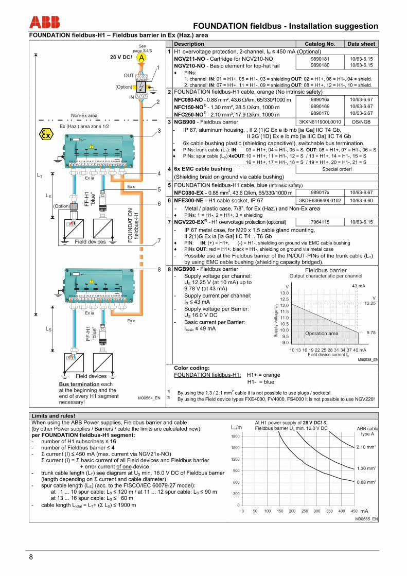
FOUNDATION fieldbus-H1 – Fieldbus barrier in Ex (Haz.) area
Description Catalog No. Data sheet
1 H1 overvoltage protection, 2-channel, IN ≤ 450 mA (Optional) NGV211-NO - Cartridge for NGV210-NO NGV210-NO - Basic element for top-hat rail
9890181 9890180
10/63-6.15 10/63-6.15
♦ PINs: 1. channel: IN: 01 = H1+, 05 = H1-, 03 = shielding OUT: 02 = H1+, 06 = H1-, 04 = shield. 2. channel: IN: 07 = H1+, 11 = H1-, 09 = shielding OUT: 08 = H1+, 12 = H1-, 10 = shield.
2 FOUNDATION fieldbus-H1 cable, orange (No intrinsic safety)
NFC080-NO - 0.88 mm², 43.6 /km, 65/330/1000 m NFC150-NO1) - 1.30 mm², 28.5 /km, 1000 m NFC250-NO1) - 2.10 mm², 17.9 /km, 1000 m
989016x
9890169
9890170
10/63-6.67
10/63-6.67
10/63-6.67
3 NGB900 - Fieldbus barrier 3KXN611900L0010 DS/NGB
- IP 67, aluminum housing, , II 2 (1)G Ex e ib mb [ia Ga] IIC T4 Gb, II 2G (1D) Ex e ib mb [ia IIIC Da] IIC T4 Gb
- 6x cable bushing plastic (shielding capacitive!), switchable bus termination. ♦ PINs: trunk cable (LT): IN: 03 = H1+, 04 = H1-, 05 = S OUT: 08 = H1+, 07 = H1-, 06 = S♦ PINs: spur cable (LS):4xOUT: 10 = H1+, 11 = H1-, 12 = S / 13 = H1+, 14 = H1-, 15 = S
16 = H1+, 17 = H1-, 18 = S / 19 = H1+, 20 = H1-, 21 = S
4 6x EMC cable bushing Special order!
(Shielding braid on ground via cable bushing)
5 FOUNDATION fieldbus-H1 cable, blue (Intrinsic safety)
NFC080-EX - 0.88 mm2, 43.6 Ω/km, 65/330/1000 m 989017x 10/63-6.67
6 NFE300-NE - H1 cable socket, IP 67 3KDE636640L0102 10/63-6.60
- Metal / plastic case, 7/8”, for Ex (Haz.) and Non-Ex area ♦ PINs: 1 = H1-, 2 = H1+, 3 = shielding
7 NGV220-EX2) - H1 overvoltage protection (optional) 7964115 10/63-6.15
- IP 67 metal case, for M20 x 1.5 cable gland mounting, II 2(1)G Ex ia [ia Ga] IIC T4 .. T6 Gb
♦ PIN: IN: (+) = H1+, (-) = H1-, shielding on ground via EMC cable bushing ♦ PINs OUT: red = H1+, black = H1-, shielding on ground via metal case
- Possible use at the Fieldbus barrier of the IN/OUT-PINs of the trunk cable (LT) by using EMC cable bushing (shielding capacity bridged).
8 NGB900 - Fieldbus barrier - Supply voltage per channel:
US 12.25 V (at 10 mA) up to 9.78 V (at 43 mA)
- Supply current per channel: IS ≤ 43 mA
- Supply voltage per Barrier: US 16.0 V DC
- Basic current per Barrier: Ibasic ≤ 49 mA
Color coding: FOUNDATION fieldbus-H1: H1+ = orange H1- = blue
1) By using the 1.3 / 2.1 mm2 cable it is not possible to use plugs / sockets! 2) By using the Field device types FXE4000, FV4000, FS4000 it is not possible to use NGV220!
Limits and rules! When using the ABB Power supplies, Fieldbus barrier and cable (by other Power supplies / Barriers / cable the limits are calculated new). per FOUNDATION fieldbus-H1 segment: - number of H1 subscribers ≤ 16 - number of Fieldbus barrier ≤ 4 - Σ current (I) ≤ 450 mA (max. current via NGV21x-NO) Σ current (I) = Σ basic current of all Field devices and Fieldbus barrier
+ error current of one device - trunk cable length (LT) see diagram at US min. 16.0 V DC of Fieldbus barrier
(length depending on Σ current and cable diameter) - spur cable length (LS) (acc. to the FISCO/IEC 60079-27 model):
at 1 ... 10 spur cable: LS ≤ 120 m / at 11 ... 12 spur cable: LS ≤ 90 m at 13 ... 16 spur cable: LS ≤ 60 m
- cable length Ltotal = LT+ (Σ LS) ≤ 1900 m
FO
UN
DAT
ION
field
bus-
H1
Ex e
Ex ia
LS
Ex ia
A
LS
LT
(Option)
aaaaaaaaaaaaaaaaaaaaaaaaaaaaaaaaaaaaaaaaaaaaaaaaaaaaaaaaaaaaaaaaaaaaaaaa
(Option)
02 04 06
IN
OUT
01 03 05
28 V DC!
Ex e
10 11 12 13 14 1516 17 1819 20 2103 04 0506 07 08
!
10 11 12 13 14 1516 17 1819 20 2103 04 0506 07 08
!
1
2
3
4
5
6
8
7
Seepage 3/4/6
Non-Ex area
Ex (Haz.) area zone 1/2
FF
-H1
“blu
e”
Field devices
FF
-H1
“blu
e”
Field devices
Bus termination eachat the beginning and theend of every H1 segmentnecessary!
M00564_EN
0
300
600
900
1200
1500
1800
0 50 100 150 200 250 300 350 400 450 mA
L /mT
At H1 power supply of &Fieldbus barrier U min. 16.0 V DC
28 V DC!S ABB cable
type A
2.10 mm2
1.30 mm2
0.88 mm2
M00565_EN
FOUNDATION fieldbus - Installation suggestion
9
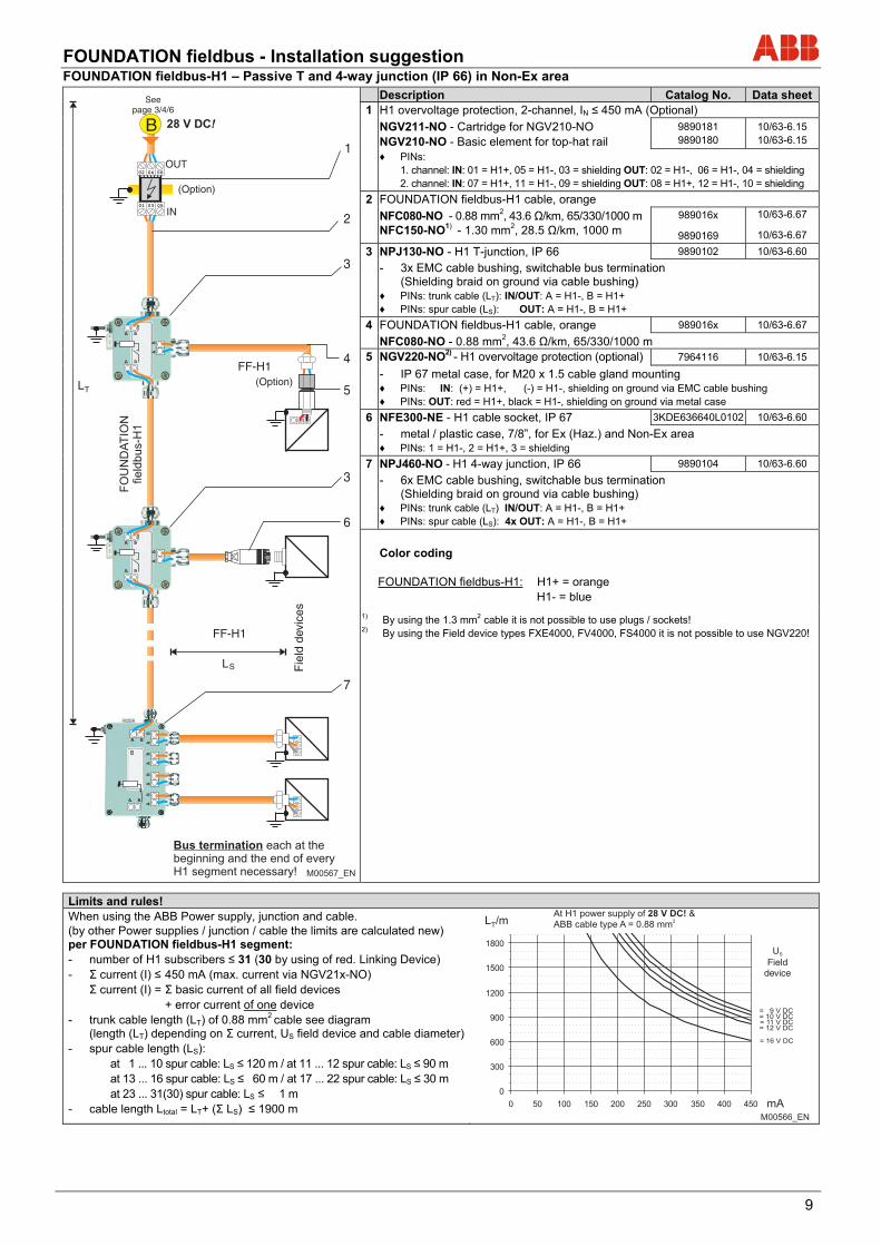
FOUNDATION fieldbus-H1 – Passive T and 4-way junction (IP 66) in Non-Ex area
Description Catalog No. Data sheet1 H1 overvoltage protection, 2-channel, IN ≤ 450 mA (Optional)
NGV211-NO - Cartridge for NGV210-NO NGV210-NO - Basic element for top-hat rail
9890181 9890180
10/63-6.15 10/63-6.15
♦ PINs: 1. channel: IN: 01 = H1+, 05 = H1-, 03 = shielding OUT: 02 = H1-, 06 = H1-, 04 = shielding 2. channel: IN: 07 = H1+, 11 = H1-, 09 = shielding OUT: 08 = H1+, 12 = H1-, 10 = shielding
2 FOUNDATION fieldbus-H1 cable, orange NFC080-NO - 0.88 mm2, 43.6 Ω/km, 65/330/1000 m
NFC150-NO1) - 1.30 mm2, 28.5 Ω/km, 1000 m 989016x
9890169
10/63-6.67
10/63-6.67
3 NPJ130-NO - H1 T-junction, IP 66 9890102 10/63-6.60
- 3x EMC cable bushing, switchable bus termination (Shielding braid on ground via cable bushing)
♦ PINs: trunk cable (LT): IN/OUT: A = H1-, B = H1+ ♦ PINs: spur cable (LS): OUT: A = H1-, B = H1+
4 FOUNDATION fieldbus-H1 cable, orange 989016x 10/63-6.67
NFC080-NO - 0.88 mm2, 43.6 Ω/km, 65/330/1000 m 5 NGV220-NO2) - H1 overvoltage protection (optional) 7964116 10/63-6.15
- IP 67 metal case, for M20 x 1.5 cable gland mounting ♦ PINs: IN: (+) = H1+, (-) = H1-, shielding on ground via EMC cable bushing ♦ PINs: OUT: red = H1+, black = H1-, shielding on ground via metal case
6 NFE300-NE - H1 cable socket, IP 67 3KDE636640L0102 10/63-6.60
- metal / plastic case, 7/8”, for Ex (Haz.) and Non-Ex area ♦ PINs: 1 = H1-, 2 = H1+, 3 = shielding
7 NPJ460-NO - H1 4-way junction, IP 66 9890104 10/63-6.60
- 6x EMC cable bushing, switchable bus termination (Shielding braid on ground via cable bushing)
♦ PINs: trunk cable (LT) IN/OUT: A = H1-, B = H1+ ♦ PINs: spur cable (LS): 4x OUT: A = H1-, B = H1+
Color coding FOUNDATION fieldbus-H1: H1+ = orange H1- = blue
1) By using the 1.3 mm2 cable it is not possible to use plugs / sockets! 2) By using the Field device types FXE4000, FV4000, FS4000 it is not possible to use NGV220!
Limits and rules! When using the ABB Power supply, junction and cable. (by other Power supplies / junction / cable the limits are calculated new) per FOUNDATION fieldbus-H1 segment: - number of H1 subscribers ≤ 31 (30 by using of red. Linking Device) - Σ current (I) ≤ 450 mA (max. current via NGV21x-NO) Σ current (I) = Σ basic current of all field devices + error current of one device - trunk cable length (LT) of 0.88 mm2 cable see diagram
(length (LT) depending on Σ current, US field device and cable diameter)- spur cable length (LS):
at 1 ... 10 spur cable: LS ≤ 120 m / at 11 ... 12 spur cable: LS ≤ 90 m at 13 ... 16 spur cable: LS ≤ 60 m / at 17 ... 22 spur cable: LS ≤ 30 m at 23 ... 31(30) spur cable: LS ≤ 1 m
- cable length Ltotal = LT+ (Σ LS) ≤ 1900 m
(Option)
LT
FO
UN
DA
TIO
Nfie
ldb
us-H
1
FF-H1
aaaaaaaaaaaaaaaaaaaaaaaaaaaaaaaaaaaaaaaaaaaaaaaaaaaaaaaaaaaaaaaaaaaaaaaa02 04 06
IN
OUT
01 03 05
B
(Option)
LS
A B
A B
A B
FF-H1
A B
28 V DC!
1
2
3
3
5
7
6
4
A B
A B
A B
A B
A B
A B
A B
A B
Seepage 3/4/6
Fie
ld d
evic
es
Bus termination each at thebeginning and the end of everyH1 segment necessary! M00567_EN
0
300
600
900
1200
1500
1800
0 50 100 150 200 250 300 350 400 450 mA
L /mT
= 9 V DC= 10 V DC= 11 V DC= 12 V DC
= 16 V DC
At H1 power supply of &ABB cable type A = 0.88 mm
28 V DC!2
UField
device
S
M00566_EN
FOUNDATION fieldbus - Installation suggestion
10
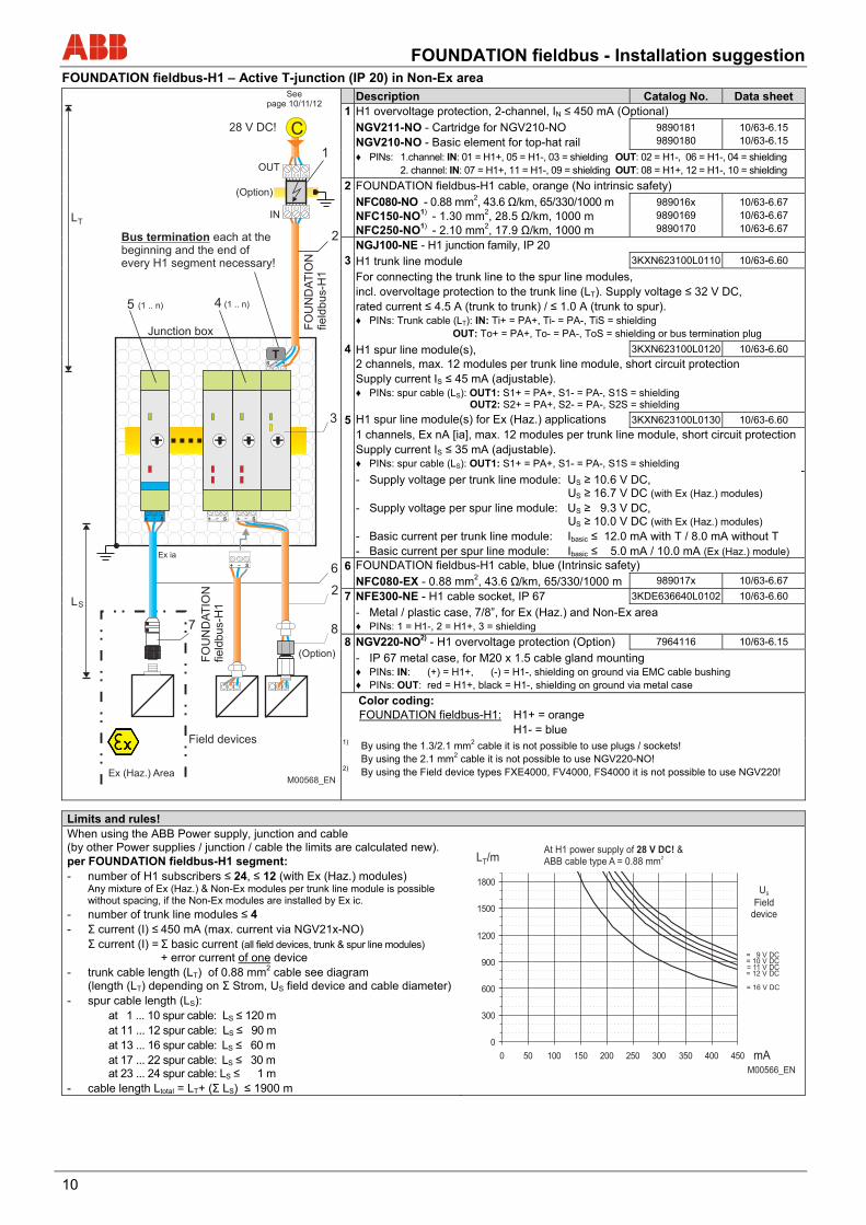
FOUNDATION fieldbus-H1 – Active T-junction (IP 20) in Non-Ex area
Description Catalog No. Data sheet 1 H1 overvoltage protection, 2-channel, IN ≤ 450 mA (Optional)
NGV211-NO - Cartridge for NGV210-NO NGV210-NO - Basic element for top-hat rail
9890181 9890180
10/63-6.15 10/63-6.15
♦ PINs: 1.channel: IN: 01 = H1+, 05 = H1-, 03 = shielding OUT: 02 = H1-, 06 = H1-, 04 = shielding 2. channel: IN: 07 = H1+, 11 = H1-, 09 = shielding OUT: 08 = H1+, 12 = H1-, 10 = shielding
2 FOUNDATION fieldbus-H1 cable, orange (No intrinsic safety) NFC080-NO - 0.88 mm2, 43.6 Ω/km, 65/330/1000 m
NFC150-NO1) - 1.30 mm2, 28.5 Ω/km, 1000 m NFC250-NO1) - 2.10 mm2, 17.9 Ω/km, 1000 m
989016x 9890169 9890170
10/63-6.67 10/63-6.67 10/63-6.67
NGJ100-NE - H1 junction family, IP 20
3 H1 trunk line module 3KXN623100L0110 10/63-6.60
For connecting the trunk line to the spur line modules, incl. overvoltage protection to the trunk line (LT). Supply voltage ≤ 32 V DC, rated current ≤ 4.5 A (trunk to trunk) / ≤ 1.0 A (trunk to spur). ♦ PINs: Trunk cable (LT): IN: Ti+ = PA+, Ti- = PA-, TiS = shielding OUT: To+ = PA+, To- = PA-, ToS = shielding or bus termination plug
4 H1 spur line module(s), 3KXN623100L0120 10/63-6.60
2 channels, max. 12 modules per trunk line module, short circuit protection Supply current IS ≤ 45 mA (adjustable). ♦ PINs: spur cable (LS): OUT1: S1+ = PA+, S1- = PA-, S1S = shielding OUT2: S2+ = PA+, S2- = PA-, S2S = shielding
5 H1 spur line module(s) for Ex (Haz.) applications 3KXN623100L0130 10/63-6.60
1 channels, Ex nA [ia], max. 12 modules per trunk line module, short circuit protection Supply current IS ≤ 35 mA (adjustable). ♦ PINs: spur cable (LS): OUT1: S1+ = PA+, S1- = PA-, S1S = shielding
- Supply voltage per trunk line module: US ≥ 10.6 V DC, US ≥ 16.7 V DC (with Ex (Haz.) modules)
- Supply voltage per spur line module: US ≥ 9.3 V DC, US ≥ 10.0 V DC (with Ex (Haz.) modules)
- Basic current per trunk line module: Ibasic ≤ 12.0 mA with T / 8.0 mA without T - Basic current per spur line module: Ibasic ≤ 5.0 mA / 10.0 mA (Ex (Haz.) module)
6 FOUNDATION fieldbus-H1 cable, blue (Intrinsic safety) NFC080-EX - 0.88 mm2, 43.6 Ω/km, 65/330/1000 m 989017x 10/63-6.67
7 NFE300-NE - H1 cable socket, IP 67 3KDE636640L0102 10/63-6.60
- Metal / plastic case, 7/8”, for Ex (Haz.) and Non-Ex area ♦ PINs: 1 = H1-, 2 = H1+, 3 = shielding
8 NGV220-NO2) - H1 overvoltage protection (Option) 7964116 10/63-6.15
- IP 67 metal case, for M20 x 1.5 cable gland mounting ♦ PINs: IN: (+) = H1+, (-) = H1-, shielding on ground via EMC cable bushing ♦ PINs: OUT: red = H1+, black = H1-, shielding on ground via metal case
Color coding: FOUNDATION fieldbus-H1: H1+ = orange H1- = blue
1) By using the 1.3/2.1 mm2 cable it is not possible to use plugs / sockets! By using the 2.1 mm2 cable it is not possible to use NGV220-NO! 2) By using the Field device types FXE4000, FV4000, FS4000 it is not possible to use NGV220!
Limits and rules! When using the ABB Power supply, junction and cable (by other Power supplies / junction / cable the limits are calculated new). per FOUNDATION fieldbus-H1 segment: - number of H1 subscribers ≤ 24, ≤ 12 (with Ex (Haz.) modules)
Any mixture of Ex (Haz.) & Non-Ex modules per trunk line module is possible without spacing, if the Non-Ex modules are installed by Ex ic.
- number of trunk line modules ≤ 4 - Σ current (I) ≤ 450 mA (max. current via NGV21x-NO) Σ current (I) = Σ basic current (all field devices, trunk & spur line modules)
+ error current of one device - trunk cable length (LT) of 0.88 mm2 cable see diagram
(length (LT) depending on Σ Strom, US field device and cable diameter) - spur cable length (LS):
at 1 ... 10 spur cable: LS ≤ 120 m at 11 ... 12 spur cable: LS ≤ 90 m at 13 ... 16 spur cable: LS ≤ 60 m at 17 ... 22 spur cable: LS ≤ 30 m
at 23 ... 24 spur cable: LS ≤ 1 m - cable length Ltotal = LT+ (Σ LS) ≤ 1900 m
0
300
600
900
1200
1500
1800
0 50 100 150 200 250 300 350 400 450 mA
L /mT
= 9 V DC= 10 V DC= 11 V DC= 12 V DC
= 16 V DC
At H1 power supply of &ABB cable type A = 0.88 mm
28 V DC!2
UField
device
S
M00566_EN
FOUNDATION fieldbus - Installation suggestion
11
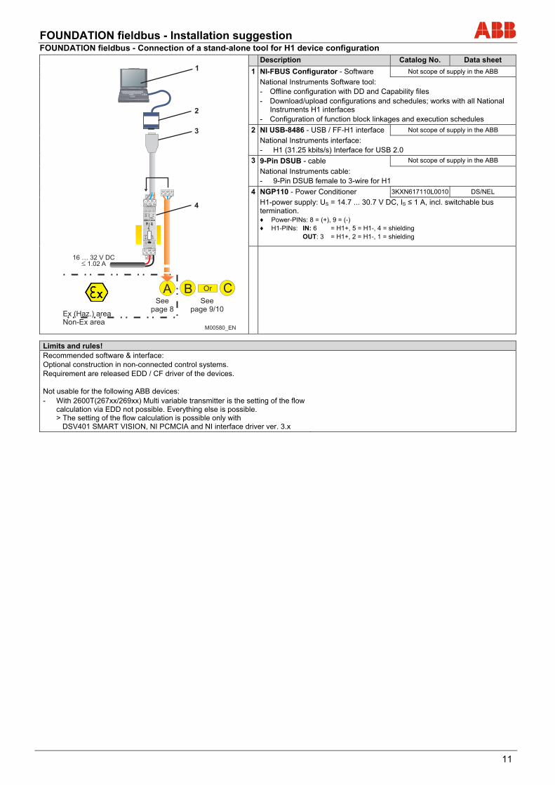
FOUNDATION fieldbus - Connection of a stand-alone tool for H1 device configuration
Description Catalog No. Data sheet
1 NI-FBUS Configurator - Software Not scope of supply in the ABB
National Instruments Software tool: - Offline configuration with DD and Capability files - Download/upload configurations and schedules; works with all National
Instruments H1 interfaces - Configuration of function block linkages and execution schedules
2 NI USB-8486 - USB / FF-H1 interface Not scope of supply in the ABB
National Instruments interface: - H1 (31.25 kbits/s) Interface for USB 2.0
3 9-Pin DSUB - cable Not scope of supply in the ABB
National Instruments cable: - 9-Pin DSUB female to 3-wire for H1
4 NGP110 - Power Conditioner 3KXN617110L0010 DS/NEL
H1-power supply: US = 14.7 ... 30.7 V DC, IS ≤ 1 A, incl. switchable bus termination. ♦ Power-PINs: 8 = (+), 9 = (-) ♦ H1-PINs: IN: 6 = H1+, 5 = H1-, 4 = shielding OUT: 3 = H1+, 2 = H1-, 1 = shielding
Limits and rules! Recommended software & interface: Optional construction in non-connected control systems. Requirement are released EDD / CF driver of the devices. Not usable for the following ABB devices: - With 2600T(267xx/269xx) Multi variable transmitter is the setting of the flow
calculation via EDD not possible. Everything else is possible. > The setting of the flow calculation is possible only with DSV401 SMART VISION, NI PCMCIA and NI interface driver ver. 3.x
FOUNDATION fieldbus - Installation suggestion
12
FOUNDATION fieldbus - Installation suggestion
13
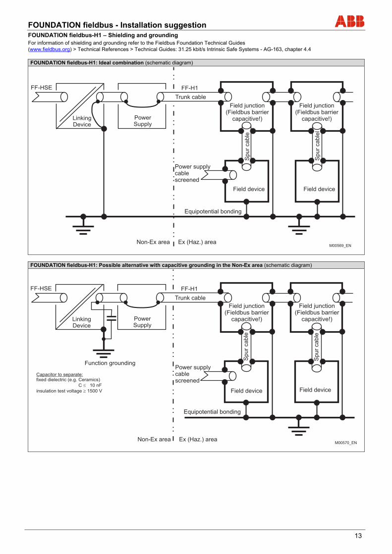
FOUNDATION fieldbus-H1 – Shielding and grounding For information of shielding and grounding refer to the Fieldbus Foundation Technical Guides (www.fieldbus.org) > Technical References > Technical Guides: 31.25 kbit/s Intrinsic Safe Systems - AG-163, chapter 4.4 FOUNDATION fieldbus-H1: Ideal combination (schematic diagram)
FOUNDATION fieldbus-H1: Possible alternative with capacitive grounding in the Non-Ex area (schematic diagram)
FOUNDATION fieldbus - Installation suggestion
14
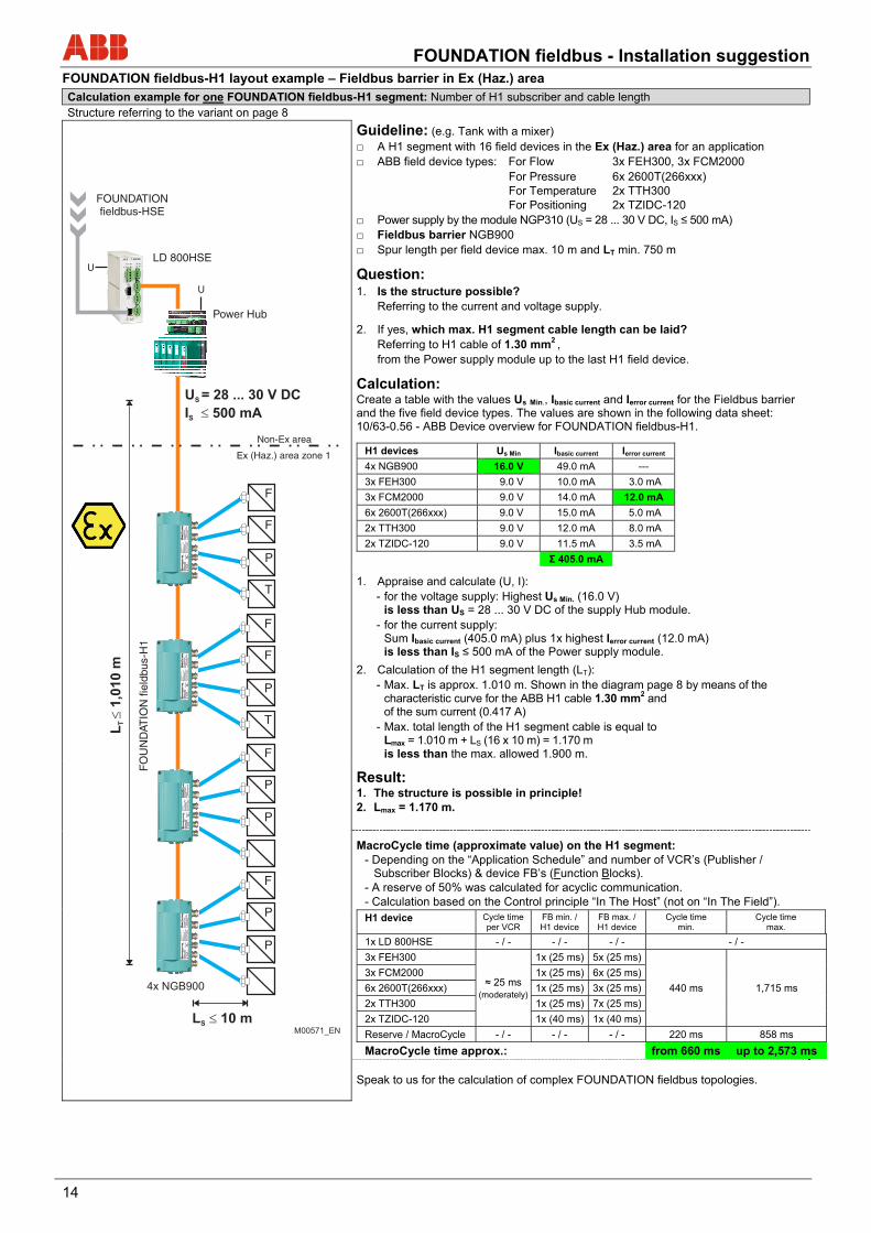
FOUNDATION fieldbus-H1 layout example – Fieldbus barrier in Ex (Haz.) area Calculation example for one FOUNDATION fieldbus-H1 segment: Number of H1 subscriber and cable length Structure referring to the variant on page 8
Guideline: (e.g. Tank with a mixer) A H1 segment with 16 field devices in the Ex (Haz.) area for an application ABB field device types: For Flow 3x FEH300, 3x FCM2000 For Pressure 6x 2600T(266xxx) For Temperature 2x TTH300 For Positioning 2x TZIDC-120 Power supply by the module NGP310 (US = 28 ... 30 V DC, IS ≤ 500 mA) Fieldbus barrier NGB900 Spur length per field device max. 10 m and LT min. 750 m
Question: 1. Is the structure possible? Referring to the current and voltage supply.
2. If yes, which max. H1 segment cable length can be laid? Referring to H1 cable of 1.30 mm2 , from the Power supply module up to the last H1 field device.
Calculation: Create a table with the values Us Min., Ibasic current and Ierror current for the Fieldbus barrier and the five field device types. The values are shown in the following data sheet: 10/63-0.56 - ABB Device overview for FOUNDATION fieldbus-H1.
H1 devices Us Min Ibasic current Ierror current
4x NGB900 16.0 V 49.0 mA ---
3x FEH300 9.0 V 10.0 mA 3.0 mA
3x FCM2000 9.0 V 14.0 mA 12.0 mA
6x 2600T(266xxx) 9.0 V 15.0 mA 5.0 mA
2x TTH300 9.0 V 12.0 mA 8.0 mA
2x TZIDC-120 9.0 V 11.5 mA 3.5 mA
Σ 405.0 mA
1. Appraise and calculate (U, I): - for the voltage supply: Highest Us Min. (16.0 V)
is less than US = 28 ... 30 V DC of the supply Hub module. - for the current supply:
Sum Ibasic current (405.0 mA) plus 1x highest Ierror current (12.0 mA) is less than IS ≤ 500 mA of the Power supply module.
2. Calculation of the H1 segment length (LT): - Max. LT is approx. 1.010 m. Shown in the diagram page 8 by means of the
characteristic curve for the ABB H1 cable 1.30 mm2 and of the sum current (0.417 A)
- Max. total length of the H1 segment cable is equal to Lmax = 1.010 m + LS (16 x 10 m) = 1.170 m is less than the max. allowed 1.900 m.
Result: 1. The structure is possible in principle! 2. Lmax = 1.170 m.
MacroCycle time (approximate value) on the H1 segment: - Depending on the “Application Schedule” and number of VCR’s (Publisher /
Subscriber Blocks) & device FB’s (Function Blocks). - A reserve of 50% was calculated for acyclic communication. - Calculation based on the Control principle “In The Host” (not on “In The Field”). H1 device Cycle time
per VCR FB min. / H1 device
FB max. / H1 device
Cycle time min.
Cycle time max.
1x LD 800HSE - / - - / - - / - - / -
3x FEH300
≈ 25 ms (moderately)
1x (25 ms) 5x (25 ms)
440 ms 1,715 ms
3x FCM2000 1x (25 ms) 6x (25 ms)
6x 2600T(266xxx) 1x (25 ms) 3x (25 ms)
2x TTH300 1x (25 ms) 7x (25 ms)
2x TZIDC-120 1x (40 ms) 1x (40 ms)
Reserve / MacroCycle - / - - / - - / - 220 ms 858 ms
MacroCycle time approx.: from 660 ms up to 2,573 ms
Speak to us for the calculation of complex FOUNDATION fieldbus topologies.
U
FOUNDATIONfieldbus-HSE
LD 800HSE
F
P
F
F
P
T
F
F
P
T
L 10 mS
F
P
P
P
FO
UN
DAT
ION
fiel
dbus
-H1
4x NGB900
U
Power Hub
U = 28 ... 30 V DC
I 500 mA
S
S
L1
,01
0 m
T
Ex (Haz.) area zone 1
Non-Ex area
M00571_EN
FOUNDATION fieldbus - Installation suggestion
15
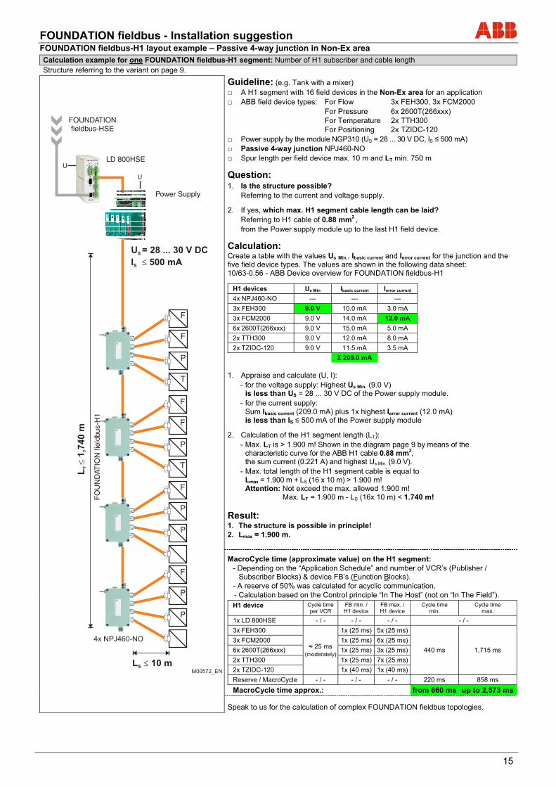
FOUNDATION fieldbus-H1 layout example – Passive 4-way junction in Non-Ex area Calculation example for one FOUNDATION fieldbus-H1 segment: Number of H1 subscriber and cable length Structure referring to the variant on page 9.
Guideline: (e.g. Tank with a mixer) A H1 segment with 16 field devices in the Non-Ex area for an application ABB field device types: For Flow 3x FEH300, 3x FCM2000 For Pressure 6x 2600T(266xxx) For Temperature 2x TTH300 For Positioning 2x TZIDC-120 Power supply by the module NGP310 (US = 28 ... 30 V DC, IS ≤ 500 mA) Passive 4-way junction NPJ460-NO Spur length per field device max. 10 m and LT min. 750 m
Question: 1. Is the structure possible? Referring to the current and voltage supply.
2. If yes, which max. H1 segment cable length can be laid? Referring to H1 cable of 0.88 mm2 , from the Power supply module up to the last H1 field device.
Calculation: Create a table with the values Us Min., Ibasic current and Ierror current for the junction and the five field device types. The values are shown in the following data sheet: 10/63-0.56 - ABB Device overview for FOUNDATION fieldbus-H1
H1 devices Us Min Ibasic current Ierror current
4x NPJ460-NO --- --- ---
3x FEH300 9.0 V 10.0 mA 3.0 mA
3x FCM2000 9.0 V 14.0 mA 12.0 mA
6x 2600T(266xxx) 9.0 V 15.0 mA 5.0 mA
2x TTH300 9.0 V 12.0 mA 8.0 mA
2x TZIDC-120 9.0 V 11.5 mA 3.5 mA
Σ 209.0 mA
1. Appraise and calculate (U, I): - for the voltage supply: Highest Us Min. (9.0 V)
is less than US = 28 ... 30 V DC of the Power supply module. - for the current supply:
Sum Ibasic current (209.0 mA) plus 1x highest Ierror current (12.0 mA) is less than IS ≤ 500 mA of the Power supply module
2. Calculation of the H1 segment length (LT): - Max. LT is > 1.900 m! Shown in the diagram page 9 by means of the
characteristic curve for the ABB H1 cable 0.88 mm2, the sum current (0.221 A) and highest Us Min. (9.0 V).
- Max. total length of the H1 segment cable is equal to Lmax = 1.900 m + LS (16 x 10 m) > 1.900 m! Attention: Not exceed the max. allowed 1.900 m! Max. LT = 1.900 m - LS (16x 10 m) < 1.740 m!
Result: 1. The structure is possible in principle! 2. Lmax = 1.900 m.
MacroCycle time (approximate value) on the H1 segment: - Depending on the “Application Schedule” and number of VCR’s (Publisher /
Subscriber Blocks) & device FB’s (Function Blocks). - A reserve of 50% was calculated for acyclic communication. - Calculation based on the Control principle “In The Host” (not on “In The Field”). H1 device Cycle time
per VCR FB min. / H1 device
FB max. / H1 device
Cycle time min.
Cycle time max.
1x LD 800HSE - / - - / - - / - - / -
3x FEH300
≈ 25 ms (moderately)
1x (25 ms) 5x (25 ms)
440 ms 1,715 ms
3x FCM2000 1x (25 ms) 6x (25 ms)
6x 2600T(266xxx) 1x (25 ms) 3x (25 ms)
2x TTH300 1x (25 ms) 7x (25 ms)
2x TZIDC-120 1x (40 ms) 1x (40 ms)
Reserve / MacroCycle - / - - / - - / - 220 ms 858 ms
MacroCycle time approx.: from 660 ms up to 2,573 ms
Speak to us for the calculation of complex FOUNDATION fieldbus topologies.
U
FOUNDATIONfieldbus-HSE
LD 800HSE
F
P
F
F
P
T
F
F
P
T
L 10 mS
F
P
P
P
4x NPJ460-NO
U
Power Supply
U = 28 ... 30 V DC
I 500 mA
S
S
FO
UN
DAT
ION
fiel
dbus
-H1
L1
,74
0 m
T
M00572_EN
Contact us
10/6
3-0.
50 E
N R
ev. D
01.
2015ABB Automation GmbH
Service Instrumentation Kallstadter Straße 1 68309 Mannheim Germany Customer Service Center: +49 180 5 222 580* E-Mail: [email protected] www.abb.com/measurement * 14 cents/minute from German landlines, max. 42 cents/minute from mobiles.
Note We reserve the right to make technical changes or modify the contents of this document without prior notice. With regard to purchase orders, the agreed particulars shall prevail. ABB does not accept any responsibility whatsoever for potential errors or possible lack of information in this document. We reserve all rights in this document and in the subject matter and illustrations contained therein. Any reproduction, disclosure to third parties or utilization of its contents - in whole or in parts – is forbidden without prior written consent of ABB. Copyright© 2015 ABB All rights reserved 3KXN050000R1001
Sales Service


