© PHOENIX CONTACT - 2010-09-28101972_en_08
INTERFACE
PSI-MOS-PROFIB/FO…
Data sheet
1 Description
PSI-MOS-PROFIB/FO… devices convert copper-based
PROFIBUS DP interfaces to fiber optics. The devices can
also be used in MPI networks (not in ring structures). A
transparent protocol is used to convert all transmission
speeds up to a maximum of 12 Mbps. The integrated optical
diagnostics enable fiber optic paths to be monitored
continuously during installation and even during operation.
The floating switch contact is activated when the signal level
on the fiber optic paths reaches a critical value. This early
alarm generation enables critical system states to be
diagnosed before they result in failure.
The main advantage of this system is the electrically
isolated connection of devices, which prevents the negative
effects of voltage equalization currents and electromagnetic
interference on the data cables. This increases the overall
availability of the system, and improves flexibility in terms of
the design of the bus topology in a linear, star, tree or ring
structure.
PSI-MOS-PROFIB/FO… E termination devices convert a
PROFIBUS interface to a fiber optic cable. They are ideal for
point-to-point connections.
PSI-MOS-PROFIB/FO… T T-couplers convert to two fiber
optic cables. They can be used to create redundant bus
topologies for increased system availability.
In addition, modular star distributors can be created from
both device versions. In this case, the required devices are
snapped onto DIN rail connectors, which ensure that the
supply voltage and data signals are routed through.
Virtually any cascadable star and tree structures, which are
only limited by the maximum permissible signal runtime of
the relevant application, can be created using integrated bit
retiming.
Devices with different transmission technologies (polymer,
HCS, and glass fiber) can be freely combined within a star
coupler.
PSI-MOS-PROFIB/FO 660 ... devices are networked using
polymer fiber cable for distances up to 70 m and HCS fiber
cable for up to 400 m. They are connected via F-SMA quick
mounting connectors, which can be assembled locally
within a few minutes. PSI-MOS-PROFIB/FO 850 ... devices
are available for longer paths and can be used for distances
up to 800 m using HCS fiber cable and B-FOC fast
connection technology and up to 3300 m using multi-mode
glass fiber cable.
Fiber optic converter for PROFIBUS up to 12 Mbps
If you have any technical problems, which you cannot resolve with the aid of this documentation, please contact
us during the usual office hours at:
Phone: + 49 52 35 3-19890
Fax: + 49 52 35 3-30999
E-mail: [email protected]
Make sure you always use the latest documentation.
It can be downloaded at www.phoenixcontact.net/catalog.
This data sheet is valid for all products listed on the following page:

PSI-MOS-PROFIB/FO…
101972_en_08 PHOENIX CONTACT 2
Table of contents
1 Description.................................................................................................................................. 1
2 Ordering data.............................................................................................................................. 3
3 Technical data ............................................................................................................................ 4
4 Safety regulations and installation notes..................................................................................... 7
4.1 Installation and operation ............................................................................................................................... 7
4.2 Installation in zone 2....................................................................................................................................... 7
5 Supported network structures..................................................................................................... 8
5.1 Point-to-point connections.............................................................................................................................. 8
5.2 Linear structures............................................................................................................................................. 8
5.3 Star structures ................................................................................................................................................ 8
5.4 Tree structures ............................................................................................................................................... 9
5.5 Redundant ring structures .............................................................................................................................. 9
6 Function elements ...................................................................................................................... 9
7 Definition of fiber optic diagnostics ............................................................................................10
7.1 Idle setting.................................................................................................................................................... 10
7.2 Basic method of operation............................................................................................................................ 10
8 Configuration .............................................................................................................................11
8.1 Setting the DIP switches............................................................................................................................... 11
8.2 Setting the transmission speed (DIP 1 - 4) ................................................................................................... 12
8.3 Echo evaluation (DIP 5)................................................................................................................................ 12
8.4 Connection to fiber optic interfaces from third-party suppliers (DIP 5/6) ....................................................... 13
8.5 Redundancy function (DIP 7/9) .................................................................................................................... 13
8.6 Disabling the second fiber optic port (DIP 8) ................................................................................................ 14
8.7 Activating enhanced ring management (DIP 7/9) ......................................................................................... 14
8.8 Activating FIBER CONTROL function (DIP 10) ............................................................................................ 14
8.9 Mixed operation of PSI-MOS and PSM-EG.................................................................................................. 14
9 Connection notes.......................................................................................................................16
9.1 Combined assembly with a system power supply unit (modular star coupler) .............................................. 16
9.2 Assembly as an individual device in the control cabinet (stand-alone) ......................................................... 17
9.3 Assembly in potentially explosive areas ....................................................................................................... 17
9.4 Removal ....................................................................................................................................................... 17
10 Cabling notes.............................................................................................................................18
10.1 Connecting the supply voltage ..................................................................................................................... 18
10.2 Connecting the data cables.......................................................................................................................... 18
10.3 Wiring the switch contact.............................................................................................................................. 19
10.4 Connecting the fiber optic cables ................................................................................................................. 20
11 Configuration rules.....................................................................................................................21
11.1 Configuring the network parameters (PSI-MOS devices with 10-pos. DIP switch) ....................................... 21
11.2 Configuring the network parameters (PSI-MOS devices with 8-pos. DIP switch) ......................................... 24

PSI-MOS-PROFIB/FO…
101972_en_08 PHOENIX CONTACT 3
2 Ordering data
Other fiber optic converters in the PSI-MOS system
PSI-MOS-PROFIB/FO 1300… devices are networked for
distances up to 25 km using multi-mode glass fiber cable
and up to 45 km using single mode glass fiber cable.
Fiber optic converters
Description Type Order No. Pcs./Pkt.
Termination device with one fiber optic interface
Fiber optic converter with integrated optical diagnostics, alarm contact, for
PROFIBUS up to 12 Mbps
660 nm, for polymer/HCS fiber cable, F-SMA
850 nm, for glass fiber cable, B-FOC (ST®
)
PSI-MOS-PROFIB/FO 660 E
PSI-MOS-PROFIB/FO 850 E
2708290
2708274
1
1
T-coupler with two fiber optic interfaces
Fiber optic converter with integrated optical diagnostics, alarm contact, for
PROFIBUS up to 12 Mbps
660 nm, for polymer/HCS fiber cable, F-SMA
850 nm, for glass fiber cable, B-FOC (ST®
)
PSI-MOS-PROFIB/FO 660 T
PSI-MOS-PROFIB/FO 850 T
2708287
2708261
1
1
Accessories
Description Type Order No. Pcs./Pkt.
System power supply unit for supplying a modular star coupler topology MINI-SYS-PS 100-240AC/24DC/1.5 2866983 1
Power supply unit for use in potentially explosive areas MINI-PS-100-240AC/24DC/1.5/EX 2866653 1
End clamps CLIPFIX 35 3022218 50
DIN rail connector, power supply and data (2 per device) ME 17,5 TBUS1,5/5-ST-3,81GN 2709561 10
DIN rail connector, power supply only (2 per device) ME 17,5 TBUS1,5/PP000-3,81BK 2890014 10
Small, angled PROFIBUS connector with screw connection SUBCON-PLUS-PROFIB/SC2 2708232 1
Small, angled PROFIBUS connector with screw connection and additional
PG connection
SUBCON-PLUS-PROFIB/PG/SC2 2708245 1
Polymer fiber connectors (4 connectors in the set) PSM-SET-FSMA/4-KT 2799720 1
Polishing set for polymer fiber connectors
(required to assemble polymer fiber connectors)
PSM-SET-FSMA-POLISH 2799348 1
Fiber optic polymer fiber cable for indoor installation PSM-LWL-KDHEAVY 2744319 1
F-SMA HCS fiber connectors (4 connectors in the set) PSM-SET-FSMA/4-HCS 2799487 1
B-FOC (ST®
) HCS fiber connectors (4 connectors in the set) PSM-SET-B-FOC/4-HCS 2708481 1
Tool set for HCS connectors (F-SMA)
(required for HCS connector assembly)
PSM-HCS-KONFTOOL 2799526 1
Tool set for HCS connectors (B-FOC (ST®
))
(required for HCS connector assembly)
PSM-HCS-KONFTOOL/B-FOC 2708465 1
Tool set for F-SMA and SCRJ connectors (polymer fiber) PSM-POF-KONFTOOL 2744131 1
Fiber optic HCS cable for indoor installation PSM-LWL-HCS RUGGED-200/230 2799885 1
Fiber optic HCS cable for outdoor installation PSM-LWL-HCSO-200/230 2799445 1
Fiber optic glass fiber cable for indoor installation PSM-LWL-GDM-RUGGED-50/125 2799322 1
Fiber optic glass fiber cable for outdoor installation PSM-LWL-GDO-50/125 2799432 1
Measuring device for fiber optic power measurement PSM-FO-POWERMETER 2799539 1
Other fiber optic converters
Description Type Order No. Pcs./Pkt.
Fiber optic converter with integrated optical diagnostics, alarm contact, for
PROFIBUS up to 12 Mbps, 1300 nm, for glass fiber cable, SC duplex
Termination device with one fiber optic interface
T-coupler with two fiber optic interfaces
PSI-MOS-PROFIB/FO 1300 E
PSI-MOS-PROFIB/FO 1300 T
2708559
2708892
1
1

PSI-MOS-PROFIB/FO…
101972_en_08 PHOENIX CONTACT 4
3 Technical data
Interfaces
Power supply 24 V DC (18 V DC ... 32 V DC)
Nominal current consumption 130 mA, maximum
Ready-to-operate indicator "VCC" LED (green)
Maximum star coupler expansion 10
Serial RS-485 interface PROFIBUS FMS/DP according to IEC 61158, 2-wire, also MPI
Operating mode Half duplex
Data format/encoding UART (11 bits, NRZ)
Data direction changeover Automatic control
Transmission speed
(automatic detection or set via DIP switches)
9.6/19.2/45.45/93.75/187.5/500/1500/3000/6000/12,000 kbps
Transmission length Depending on the transmission speed up to 1200 m, maximum
Connection 9-pos. D-SUB female connector
Output voltage/current (pin 6) 5 (±0.25) V DC, 50 mA
Optical interface According to technical guideline PNO No. 2.021
Transmission protocol Transparent protocol to RS-485 interface
Connection method F-SMA B-FOC (ST®
)
Wavelength 660 nm 850 nm
Minimum transmission power (fiber type) -3.0 dBm (980/1000 μm)
-15.4 dBm (200/230 μm)
-4.2 dBm (200/230 μm)
-17.8 dBm (50/125 μm)
-14.6 dBm (62.5/125 μm)
Receiver sensitivity
Minimum
Maximum
-30.0 dBm
-3.0 dBm (980/1000 μm)
-30.0 dBm (50/125 μm)
-3.0 dBm (200/230 μm)
Minimum transmission length including 3 dB system reserve 70 m with F-P 980/1000; 230 dB/km
400 m with F-K 200/230;
10 dB/km with quick mounting
connectors
800 m with F-K 200/230;
8 dB/km with quick mounting
connectors
2600 m with F-G 50/125; 2.5 dB/km
3300 m with F-G 62.5/125; 3.0 dB/km
Minimum transmission length 1 m with F-K 200/230; 8.0 dB/km
General data
Bit distortion input ±35%, maximum
Bit distortion output < 6.25%
Bit delay in redundancy mode (DIP 7 = ON) 11 bits
Bit delay in standard mode (DIP 7 = OFF) < 1 bit
Electrical isolation RS-485//power supply
Test voltage 1.5 kVrms, 50 Hz, 1 min.
Alarm output 60 V DC/42 V AC, 1 A, maximum
Status and diagnostic indicators Power supply (VCC), transmit/receive data RS-485 PROFIBUS,
fiber optic bar graph (FO SIGNAL), fiber optic error (FO ERR)
Housing material PA V0, green
Ambient temperature
Operation
Storage/transport
-20°C ... +60°C
-40°C ... +85°C
Humidity 30% ... 95%, no condensation
Dimensions (W x H x D) 35 mm x 99 mm x 105 mm
Degree of protection IP20
Weight 190 g, approximately
MTBF according to Telcordia standard
Ambient temperature 25°C
Ambient temperature 40°C
Termination
devices (E)
660 nm
324 years
70 years
Termination
devices (E)
850 nm
252 years
42 years
T-couplers
(T)
660 nm
201 years
42 years
T-couplers
(T)
850 nm
149 years
24 years

PSI-MOS-PROFIB/FO…
101972_en_08 PHOENIX CONTACT 5
Chloroform test Free from substances that would hinder coating with paint or varnish
(according to VW/Audi/Seat specification)
Vibration resistance 5g according to IEC 60068-2-6, 2.5 h each in x, y, and z direction, criterion A
Shock resistance 15g according to IEC 60068-2-27 with 11 ms pulse length, criterion C
Free fall 1 m without packaging according to IEC 60950
Air and creepage distances DIN EN 60664-1/VDE 0110-1, DIN EN 50178, DIN EN 60950
General data (continued)
Tests/approvals
CE c
PROFIBUS interoperability Tested by independent PNO test laboratory (PN059-485-01)
ABB certification: Industrial IT Enabled
This certification is a trademark of ABB.
UL/CUL 1604 Ex listed U PROCESS CONTROL EQUIPMENT FOR HAZARDOUS
LOCATIONS
Class I, Zone 2, AEx nC IIC
Conformity assessment according to Directive 94/9/EC
Fiber optic interface as an associated item of equipment for zone 1 devices
Assembly and operation of the device in zone 2
X II (2) GD [EX op is] IIC (PTB 06 ATEX 2042u)
X II 3G Ex nAC IIC T4 X
Conformance with EMC Directive 2004/108/EC and Low Voltage Directive 2006/95/EC
Noise immunity test according to EN 61000-6-21
Electrostatic discharge (ESD)
Air discharge
Contact discharge
EN 61000-4-2 Criterion B2
8 kV
6 kV
Electromagnetic HF field
Amplitude modulation
EN 61000-4-3 Criterion A3
10 V/m
Fast transients (burst)
Signal
Power supply
EN 61000-4-4 Criterion B2
2 kV/5 kHz
2 kV/5 kHz
Surge current load (surge)
Signal
Power supply
EN 61000-4-5 Criterion B2
1 kV/42 Ω
0.5 kV/2 Ω
Conducted interference EN 61000-4-6 Criterion A3
10 V
Noise emission test according to EN 61000-6-4
Noise emission of housing EN 550114
Class A5
1EN 61000 corresponds to IEC 61000
2Criterion B: Temporary adverse effects on the operating behavior, which the device corrects automatically.
3Criterion A: Normal operating behavior within the specified limits.
4EN 55011 corresponds to CISPR11
5Class A: Industrial application, without special installation measures.

PSI-MOS-PROFIB/FO…
101972_en_08 PHOENIX CONTACT 6
Block diagram
Figure 1 Block diagram
Housing dimensions
Figure 2 Housing dimensions (in mm)
DIN Rail Connector
FO Line
FO Line
Line Diagnostics Port B
Line Diagnostics Port A
Bus ManagementFunction/
Data Rate
FO Port B *)
FO Port A
*) Only for PSI-MOS-PROFIB/FO...T
Retiming
Retiming
Retiming rd
ERR A
rdERR B
DC
DC
gn
CTRL
ye
gn
TD
TD
RD
RD
24 V 0 V GND Data
A
Data
B
D-S
UB
CO
MB
ICO
N
24V (1)
0V (2)
11 (3)
12 (4)
Alarm
V (6)PP
GND (5)
Data A (8)
Data B (3)
101972A010
105
99
35
PSI-MOS-PROFIB/FO 660T
Ord. No. 27 08 287
VCC
TD
RD
ERR
A
ERR
B
FO
SIGNAL

PSI-MOS-PROFIB/FO…
101972_en_08 PHOENIX CONTACT 7
4 Safety regulations and installation notes
4.1 Installation and operation
Follow the installation instructions.
When installing and operating the device, the applicable
safety directives (including national safety directives),
accident prevention regulations, as well as general
technical regulations, must be observed.
Do not repair the device yourself, replace it with an
equivalent device. Repairs may only be carried out by the
manufacturer.
For the safety data, please refer to the operating instructions
and certificates (EC-type examination certificate, other
approvals, if necessary).
4.2 Installation in zone 2
Observe the specified conditions for use in potentially
explosive areas.
Installation in areas with a danger of dust explosions
NOTE: Installation, operation, and maintenance
may only be carried out by qualified specialist
personnel.
NOTE: The device must not be opened or
modified apart from the configuration of the DIP
switches.
NOTE: The switches that can be accessed may
only be actuated when the power supply to the
device is disconnected.
NOTE: The IP20 degree of protection
(IEC 60529/EN 60529) of the device is intended
for use in a clean and dry environment. The
device must not be subject to mechanical strain
and/or thermal loads, which exceed the limits
described.
WARNING: Explosion hazard
The device is designed for installation in zone
2 potentially explosive areas.
WARNING: Explosion hazard
Install the device in suitable housing with
IP54 protection, minimum, that meets the
requirements of EN 60079-15.
Observe the requirements of EN 60079-14.
WARNING: Explosion hazard
Disconnect the block power supply before:
– Snapping it on or disconnecting it.
– Connecting or disconnecting cables.
WARNING: Explosion hazard
Only devices which are designed for operation in
zone 2 potentially explosive areas and are
suitable for the conditions at the installation
location may be connected to the supply and
signal circuits in zone 2.
WARNING: Explosion hazard
The device must be stopped and immediately
removed from the Ex area if it is damaged or was
subject to an impermissible load or stored
incorrectly or if it malfunctions.
WARNING: Explosion hazard
The device is not designed for installation in
areas with a danger of dust explosions.
If dust is present, install the device in suitable,
approved housing.
PSI-MOS-PROFIB/FO…
101972_en_08 PHOENIX CONTACT 8
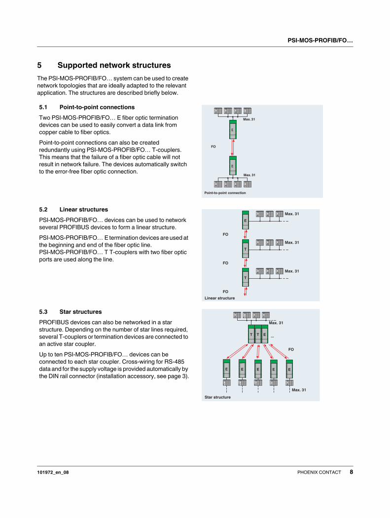
5 Supported network structures
The PSI-MOS-PROFIB/FO… system can be used to create
network topologies that are ideally adapted to the relevant
application. The structures are described briefly below.
5.1 Point-to-point connections
Two PSI-MOS-PROFIB/FO… E fiber optic termination
devices can be used to easily convert a data link from
copper cable to fiber optics.
Point-to-point connections can also be created
redundantly using PSI-MOS-PROFIB/FO… T-couplers.
This means that the failure of a fiber optic cable will not
result in network failure. The devices automatically switch
to the error-free fiber optic connection.
5.2 Linear structures
PSI-MOS-PROFIB/FO… devices can be used to network
several PROFIBUS devices to form a linear structure.
PSI-MOS-PROFIB/FO… E termination devices are used at
the beginning and end of the fiber optic line.
PSI-MOS-PROFIB/FO… T T-couplers with two fiber optic
ports are used along the line.
5.3 Star structures
PROFIBUS devices can also be networked in a star
structure. Depending on the number of star lines required,
several T-couplers or termination devices are connected to
an active star coupler.
Up to ten PSI-MOS-PROFIB/FO… devices can be
connected to each star coupler. Cross-wiring for RS-485
data and for the supply voltage is provided automatically by
the DIN rail connector (installation accessory, see page 3).
Max. 31
Max. 31
FO
Point-to-point connection
E
T
T
Linear structure
FO
FO
FO
Max. 31
Max. 31
Max. 31
T T E
E E E E
...
E
Star structure
FO
Max. 31
Max. 31

PSI-MOS-PROFIB/FO…
101972_en_08 PHOENIX CONTACT 9
6 Function elements
Figure 3 Function elements
1 24 V DC supply voltage connection
2 0 V DC supply voltage connection
3 Switch contact, connection 11
4 Switch contact, connection 12
5 9-pos. D-SUB: PROFIBUS interface
6 "VCC" LED
7 "TD" LED
8 "RD" LED
9 "FO SIGNAL" LED (port A)
10 "FO SIGNAL" LED (port A)
11 "FO SIGNAL" LED (port A)
12 "ERR" LED (port A)
13 Fiber optic transmitter (port A)
14 Fiber optic receiver (port A)
15 "FO SIGNAL" LED (port B)1
16 "FO SIGNAL" LED (port B)1
17 "FO SIGNAL" LED (port B)1
18 "ERR" LED (port B)1
19 Fiber optic transmitter (port B)1
20 Fiber optic receiver (port B)1
5.4 Tree structures
Linear and star structures can be cascaded to create
complex tree structures. The number of devices that can
be cascaded is only limited by the timing response
(timeout) of the bus system used due to the bit retiming of
the PSI-MOS-PROFIB/FO… fiber optic converter.
5.5 Redundant ring structures
If a system has increased requirements in terms of
transmission reliability and availability, redundant ring
structures can be created. If a fiber optic subsection fails in
this topology (broken fiber), all the other devices can still be
accessed. In MPI networks, redundant ring structures
cannot be created.
In the redundant ring, mixed operation of PSI-MOS with
fiber optic interfaces from other manufacturers is not
permitted.
T T
T TT T T T T T
...
... ... ... ...
max. 31 max. 31 max. 31 max. 31
max. 31
FO
FOTree structure
........
................
........
TT
T
T
max. 31
max. 31max. 31
max. 31
FO
Redundant FO ring
101972A011
PSI-MOS-PROFIB/FO 660T
Ord. No. 27 08 287
VCC
TD
RD
ERR
A
ERR
B
FO
SIGNAL
1 2 3 4
5
6
7
8
9
10
11
12
13
14
15
16
17
18
19
20
1Only for PSI-MOS-PROFIB/FO ... T
PSI-MOS-PROFIB/FO…
101972_en_08 PHOENIX CONTACT 10
Diagnostic and status indicators
7 Definition of fiber optic diagnostics
The quality of the path is determined using the incoming
optical power Popt and displayed using the LED bar graph.
DIP switch 6 is used to switch the transmitters in the idle
state (rest period between transmitting data) to steady light
(INVERS), to enable continuous fiber optic diagnostics.
If DIP 6 is set to "ON" (NORM), the echo evaluation
(DIP 5 = "OFF") is available as diagnostics. If the echo
evaluation is also switched off, fiber optic diagnostics are
not available.
As soon as the system reserve is reached, only the yellow
LED remains lit. At the same time, the signaling relay drops
and the switch contact opens. Data communication is still
possible.
In "Redundant ring" mode, the affected fiber optic port is
already switched off when the LED goes to yellow to prevent
any risk of data corruption.
7.1 Idle setting
During the idle phase, fiber optic interfaces return to an idle
setting defined by the manufacturer.
This idle setting may vary for different manufacturers and
devices. As fiber optic interfaces can only be operated
together if they have the same idle setting, this should be
observed in mixed operation with third-party devices (see
Section 8.4).
For PSI-MOS, the idle setting is specified as "Light on"
(corresponds to "Logic 1").
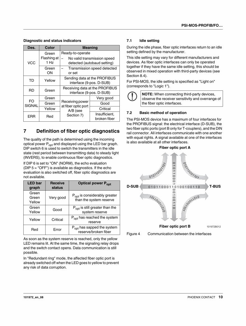
7.2 Basic method of operation
The PSI-MOS device has a maximum of four interfaces for
the PROFIBUS signal: the electrical interface (D-SUB), the
two fiber optic ports (port B only for T-couplers), and the DIN
rail connector. All interfaces communicate with one another
with equal rights. A signal available at one of the interfaces
is also available at all other interfaces.
Figure 4 Communication between the interfaces
Des. Color Meaning
VCC
Green
Flashing at
1 Hz
Ready-to-operate
– No valid transmission speed
detected (autobaud setting)
Green
ON
– Transmission speed detected
or set
TD YellowSending data at the PROFIBUS
interface (9-pos. D-SUB)
RD GreenReceiving data at the PROFIBUS
interface (9-pos. D-SUB)
FO
SIGNAL
Green
Receiving power
at fiber optic port
A/B (see
Section 7)
Very good
Green Good
Yellow Critical
ERR RedInsufficient,
broken fiber
LED bar
graph
Receive
status
Optical power Popt
Green
Green
Yellow
Very goodPopt is considerably greater
than the system reserve
Green
YellowGood
Popt is still greater than the
system reserve
Yellow CriticalPopt has reached the system
reserve
Red ErrorPopt has sapped the system
reserve/broken fiber
NOTE: When connecting third-party devices,
observe the receiver sensitivity and overrange of
the fiber optic interfaces.
101972B012
1010
0100
11
10
10
10
01
0
0111010
100100
111
01
01
00
10
01110
0 1 0 1 1 0 0 0 1 1 0 1 0 0 1 0 0 1 1 0
01
01
10
00
10
01
00
11
0
T-BUS
Fiber optic port A
Fiber optic port B
D-SUB

PSI-MOS-PROFIB/FO…
101972_en_08 PHOENIX CONTACT 11
8 Configuration
Changes to the default settings are only required in the
following cases:
– Operation with fixed transmission speed (default
setting: automatic transmission speed detection)
– Operation in a redundant ring
– Operation of a PSI-MOS-PROFIB/FO… T T-coupler
with only one fiber optic port (switch off fiber optic port B)
– Direct connection to fiber optic interfaces from other
manufacturers
– Mixed operation of PSI-MOS with the old PSM-EG
series. Usually, the different idle settings for the two
series should be adjusted.
– Mixed operation of PSI-MOS with 8-pos. and 10-pos.
DIP switches. Devices with 10-pos. DIP switches have
been supplied since April 2006 and offer enhanced
functions.
In all other cases, the devices can be operated using the
default settings.
8.1 Setting the DIP switches
• For configuration, release the housing cover using a
screwdriver (A in Figure 5).
• Then carefully pull the PCB out of the housing as far as
possible (B).
Figure 5 Opening the housing
DIP switches 1 to 10 are then freely accessible.
• Configure the DIP switches according to the planned
application.
Figure 6 Setting the DIP switches
The tables on page 12 provide an overview of the DIP switch
functions. By default upon delivery, all DIP switches are in
the "OFF" position.NOTE: Electrostatic discharge
The device contains components that can be
damaged or destroyed by electrostatic discharge.
When handling the device, observe the
necessary safety precautions against
electrostatic discharge (ESD) according to
EN 61340-5-1 and IEC 61340-5-1.
VCC
TD
RD
FO
SIGNAL
ERR
A
ERR
B
PSI-MO
S-PRO
FIB/F
O660
T
Ord
.-No. 27
08287
A
B
A
A
B
A
101972A001
NOTE: After changing the device settings,
disconnect the power to the device so that the
settings can be applied.
101972A002
S1...S10
ON
DIP
12
34
56
78
910
PSI-MOS-PROFIB/FO…
101972_en_08 PHOENIX CONTACT 12
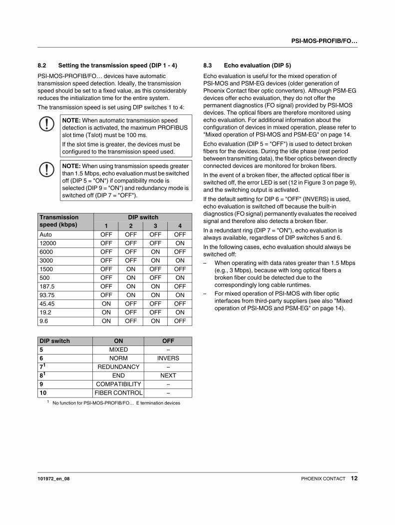
8.2 Setting the transmission speed (DIP 1 - 4)
PSI-MOS-PROFIB/FO… devices have automatic
transmission speed detection. Ideally, the transmission
speed should be set to a fixed value, as this considerably
reduces the initialization time for the entire system.
The transmission speed is set using DIP switches 1 to 4:
8.3 Echo evaluation (DIP 5)
Echo evaluation is useful for the mixed operation of
PSI-MOS and PSM-EG devices (older generation of
Phoenix Contact fiber optic converters). Although PSM-EG
devices offer echo evaluation, they do not offer the
permanent diagnostics (FO signal) provided by PSI-MOS
devices. The optical fibers are therefore monitored using
echo evaluation. For additional information about the
configuration of devices in mixed operation, please refer to
"Mixed operation of PSI-MOS and PSM-EG" on page 14.
Echo evaluation (DIP 5 = "OFF") is used to detect broken
fibers for the devices. During the idle phase (rest period
between transmitting data), the fiber optics between directly
connected devices are monitored for broken fibers.
In the event of a broken fiber, the affected optical fiber is
switched off, the error LED is set (12 in Figure 3 on page 9),
and the switching output is activated.
If the default setting for DIP 6 = "OFF" (INVERS) is used,
echo evaluation is switched off because the built-in
diagnostics (FO signal) permanently evaluates the received
signal and therefore also detects a broken fiber.
In a redundant ring (DIP 7 = "ON"), echo evaluation is
always available, regardless of DIP switches 5 and 6.
In the following cases, echo evaluation should always be
switched off:
– When operating with data rates greater than 1.5 Mbps
(e.g., 3 Mbps), because with long optical fibers a
broken fiber could be detected due to the
correspondingly long cable runtimes.
– For mixed operation of PSI-MOS with fiber optic
interfaces from third-party suppliers (see also "Mixed
operation of PSI-MOS and PSM-EG" on page 14).
NOTE: When automatic transmission speed
detection is activated, the maximum PROFIBUS
slot time (Tslot) must be 100 ms.
If the slot time is greater, the devices must be
configured to the transmission speed used.
NOTE: When using transmission speeds greater
than 1.5 Mbps, echo evaluation must be switched
off (DIP 5 = "ON") if compatibility mode is
selected (DIP 9 = "ON") and redundancy mode is
switched off (DIP 7 = "OFF").
Transmission
speed (kbps)
DIP switch
1 2 3 4
Auto OFF OFF OFF OFF
12000 OFF OFF OFF ON
6000 OFF OFF ON OFF
3000 OFF OFF ON ON
1500 OFF ON OFF OFF
500 OFF ON OFF ON
187.5 OFF ON ON OFF
93.75 OFF ON ON ON
45.45 ON OFF OFF OFF
19.2 ON OFF OFF ON
9.6 ON OFF ON OFF
DIP switch ON OFF
5 MIXED –
6 NORM INVERS
71
1No function for PSI-MOS-PROFIB/FO… E termination devices
REDUNDANCY –
81
END NEXT
9 COMPATIBILITY –
10 FIBER CONTROL –
PSI-MOS-PROFIB/FO…
101972_en_08 PHOENIX CONTACT 13
8.4 Connection to fiber optic interfaces from
third-party suppliers (DIP 5/6)
During the idle phase, fiber optic interfaces return to an idle
setting defined by the manufacturer. This idle setting may
vary for different manufacturers and devices. As fiber optic
interfaces can only be operated together if they have the
same idle setting, this should be set using the DIP switches.
For mixed operation of PSI-MOS with fiber optic interfaces
from other manufacturers, proceed as follows.
• Deactivate echo evaluation.
Set DIP 5 to "ON".
• Check the idle setting for the third-party interface:
Logic 1 = Light off
Logic 1 = Light on
• If necessary, adjust the idle setting of PSI-MOS using
DIP 6.
In the "OFF" position, the continuous measurement of
received optical power is available and the receive quality is
displayed using a 4-level bar graph (FO signal). In this case,
echo evaluation is switched off automatically.
In the "ON" position, the continuous measurement of
received optical power is not available and the 4-level bar
graph is switched off. If echo evaluation is also switched off
(DIP 5 = "ON"), broken fiber detection is not available either.
In this combination, PSI-MOS devices have no fiber optic
path diagnostics.
8.5 Redundancy function (DIP 7/9)
• For path structures, (point-to-point, linear, star, etc.)
switch off the redundancy function (DIP 7 = "OFF").
Activating the redundancy function ensures that the corre-
sponding fiber optic port is switched off as soon as the re-
ceive quality reaches "System reserve reached" (LED bar
graph on the device displays only the yellow LED), to pre-
vent any risk of data corruption.
In the redundant ring, data communication continues via the
second fiber optic port after the first fiber optic port is
switched off.
For path structures, activating the redundancy function re-
sults in the affected fiber optic port being switched off in the
event of a weak fiber optic signal (yellow LED) and thus
causes the subsequent part of the network to fail.
To overcome the restrictions regarding the ring length and
the maximum transmission speed of 1.5 Mbps, enhanced
redundancy management has been implemented in
PS-MOS devices. Enhanced redundancy management is
only available for T-couplers as a redundant ring cannot be
created using termination devices.
The new redundancy management solution is based on the
parameterization of a non-existent device in STEP 7®
. This
means that there are no restrictions regarding the ring
length, the number of devices (minimum of 3), and the max-
imum transmission speed.
To ensure compatibility with PSI-MOS devices that use the
old redundancy management solution, an additional DIP
switch (DIP 9 "COMPATIBILITY") has been added.
PSI-MOS devices with the new redundancy management
solution have a 10-pos. DIP switch range, which makes it
easy to distinguish between them and PSI-MOS devices
with the old redundancy management solution (8-pos. DIP
switch range). For mixed operation of the two PSI-MOS se-
ries, set DIP 9 to "ON".
For mixed operation of PSI-MOS devices with 8-pos. and
10-pos. DIP switches in a redundant ring, make the follow-
ing setting:
Set the other switches according to your application.
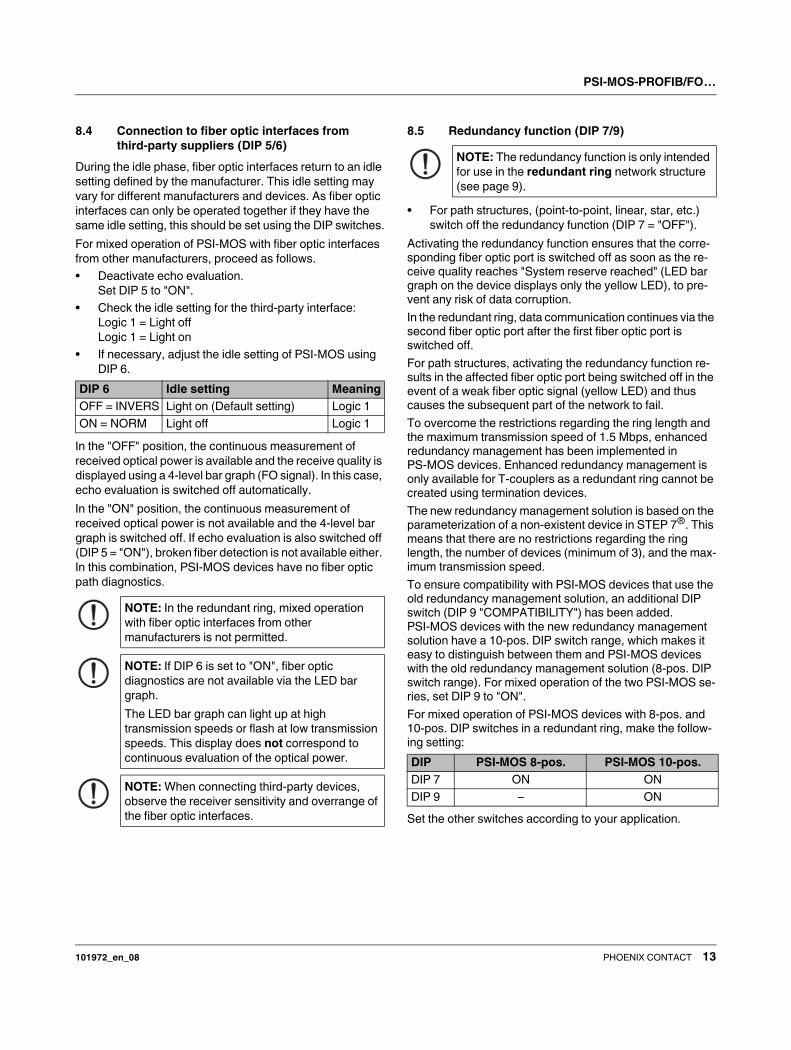
DIP 6 Idle setting Meaning
OFF = INVERS Light on (Default setting) Logic 1
ON = NORM Light off Logic 1
NOTE: In the redundant ring, mixed operation
with fiber optic interfaces from other
manufacturers is not permitted.
NOTE: If DIP 6 is set to "ON", fiber optic
diagnostics are not available via the LED bar
graph.
The LED bar graph can light up at high
transmission speeds or flash at low transmission
speeds. This display does not correspond to
continuous evaluation of the optical power.
NOTE: When connecting third-party devices,
observe the receiver sensitivity and overrange of
the fiber optic interfaces.
NOTE: The redundancy function is only intended
for use in the redundant ring network structure
(see page 9).
DIP PSI-MOS 8-pos. PSI-MOS 10-pos.
DIP 7 ON ON
DIP 9 – ON

PSI-MOS-PROFIB/FO…
101972_en_08 PHOENIX CONTACT 14
8.6 Disabling the second fiber optic port (DIP 8)
If the second fiber optic port (B) is not used for
PSI-MOS-PROFIB/FO ... T T-couplers, it must be disabled.
Otherwise the red "ERR" LED will light up.
• Set DIP 8 to "ON" (END).
8.7 Activating enhanced ring management
(DIP 7/9)
If DIP 9 is left set to "OFF" and DIP 7 is set to "ON", the
following functions are available in the redundant ring:
– Increase maximum transmission speed from 1.5 Mbps
to 12 Mbps
– No more restrictions regarding the maximum possible
ring length
– No more restrictions regarding the maximum possible
number of devices
8.8 Activating FIBER CONTROL function (DIP 10)
If in case of failure of one optical fiber, you wish to interrupt
the transmission of the telegram between two PSI-MOS
devices in both directions of the fiber optic link, activate the
function FIBER CONTROL.
• Set DIP 10 to "ON" (FIBER CONTROL).
If a fiber break is detected, the PSI-MOS device switches its
optical transmitter to steady light. Telegrams are now no
longer transmitted on both fibers.
Once the received optical power is sufficient, the device
automatically resends the received telegram.
8.9 Mixed operation of PSI-MOS and PSM-EG
Mixed operation of the old PSM-EG series with the new
PSI-MOS series is generally possible. Please note the
following settings and restrictions:
Device configuration
The DIP switch settings depend on the application
requirements. Please note that the idle setting of all devices
used in the entire system must be the same (can be set via
DIP switches) and that on new generation PSI-MOS devices
(with a 10-pos. DIP switch), DIP switch 9 must be set to
"ON".
Diagnostics in mixed operation
In mixed operation, the function of diagnostic evaluation
depends on the switch positions of the devices.
Usually PSM-EG devices are only mixed with PSI-MOS
devices when exchanged or replaced. Therefore the
following description is based on a given setting of the
PSM-EG devices, with the PSI-MOS devices being
adjusted to this setting.
If the idle setting is defined as "Light off" for PSM-EG
(DIP 6 set to "OFF"), set DIP 6 to "ON" for PSI-MOS. The FO
signal is thus no longer available to the PSI-MOS devices
and diagnostics are limited to the detection of broken fibers.
If the idle setting is defined as "Light on" for PSM-EG
(DIP 6 set to "ON"), set DIP 6 to "OFF" for PSI-MOS.
If broken fiber detection is activated for PSM-EG (DIP 7 set
to "ON"), set DIP 5 to "OFF" for PSI-MOS (mandatory in a
redundant ring). If broken fiber detection is deactivated for
PSM-EG (DIP 7 set to "OFF"), set DIP 5 to "ON" for
PSI-MOS.
If broken fiber detection is deactivated and the idle setting is
defined as "Light off", diagnostics are not available for the
fiber optic path.
Overload/underload capability of fiber optic interfaces
In rare cases (usually in the case of very short fiber optic
connections of just a few meters), an overload of the
PSI-MOS devices may occur in mixed operation. This is due
to the highly sensitive PSI-MOS receivers, which cover
large ranges but can be overloaded on very short fiber optic
paths (of just a few meters).
In the event of an overload, a patch cable with fiber optic
joint can be used to increase the attenuation of the path,
which will ensure error-free operation.
In mixed operation, observe the following ranges:
Enhanced ring management can only be used if
PSI-MOS devices with 10-pos. DIP switches are
used exclusively.
Activate this function on all PSI-MOS devices that
are connected directly to each other via fiber optic
link.Fiber Wavelength Maximum range
Glass 50/125 850 nm 1600 m
Glass 62.5/125 850 nm 2200 m
HCS Not permissible for PSM-EG
POF 660 nm 70 m

PSI-MOS-PROFIB/FO…
101972_en_08 PHOENIX CONTACT 15
(X = Any switch position)
Table 1 Switch combinations
DIP FO
diagnostic
s
Switch off
for FO
ports
Echo
evaluatio
n
Restriction
s
Operating mode Third-party
connection/mixe
d operation
5 6 7 8 9 10
X OFF OFF X OFF OFF Continuous None None None Linear/star/tree
structure
Third-party
coupler without
echo function with
"Light on" idle
setting
OFF OFF OFF X ON OFF Continuous None Activated Path length Linear/star/tree
structure
Third-party
coupler with echo
function and "Light
on" idle setting
OFF ON OFF X X OFF None None Activated Restriction
of the path
length
depending
on the
transmissio
n speed
Linear/star
structure with
"Light off" idle
setting
–
ON ON OFF X X OFF None None None None Linear/star
structure with
"Light off" idle
setting
Third-party
coupler without
echo with "Light
off" idle setting
X X ON OFF OFF OFF Continuous Yes, at low
receiving
power
Cannot be
switched
off1
1If DIP switch 7 (REDUNDANCY) is in the "ON" position and DIP switch 8 (END) is in the "OFF" position, the system
switches automatically to "Light on" idle setting with echo evaluation.
However, if fiber optic port B is switched off by setting DIP switch 8 to "ON" (END), DIP switch 7 (REDUNDANCY) has
no function.
None Standard
redundancy
mode.
Redundancy
mode with fiber
optic diagnostics,
path monitoring,
and enhanced
redundancy
management.
–
X X ON OFF ON OFF Continuous Yes, at low
receiving
power
Ring length For mixed
operation with
different
generations of
PSI-MOS devices
x OFF OFF x x ON Continuous No discon-
nection in
the event of
broken fi-
ber, tele-
grams are
no longer
transmitted
None None Linear/star/tree
structure
–

PSI-MOS-PROFIB/FO…
101972_en_08 PHOENIX CONTACT 16
9 Connection notes
• Install the device on a 35 mm DIN rail according to
DIN EN 60715.
To avoid contact resistance only use clean,
corrosion-free DIN rails.
• End clamps can be mounted on both sides of the device
to stop the devices from slipping on the DIN rail (for
ordering data see page 3).
9.1 Combined assembly with a system power
supply unit (modular star coupler)
• Connect together the required number of DIN rail
connectors for the connection station.
Two DIN rail connectors are required for each device
(see A in Figure 7).
A maximum of ten devices are permitted in a
connection station.
• Push the connected DIN rail connectors onto the DIN
rail (B and C).
• Place the device onto the DIN rail from above. The
upper holding keyway of the device must be hooked
onto the top edge of the DIN rail (see Figure 8).
Make sure that it is aligned correctly with the DIN rail
connectors.
• Once the device has been snapped on properly, check
that it is fixed securely on the DIN rail.
Figure 7 Combined assembly
WARNING: Only mount and remove devices
when the power supply is disconnected.
WARNING: PSI-MOS-... devices are designed
for SELV operation according to
IEC 60950/EN 60950/VDE 0805.
WARNING: Connect the DIN rail to protective
earth ground using a grounding terminal block.
The devices are grounded when they are
snapped onto the DIN rail (installation according
to PELV).
This ensures that the shielding is effective.
Connect protective earth ground with low
impedance.
A
B C
101973A003

PSI-MOS-PROFIB/FO…
101972_en_08 PHOENIX CONTACT 17
9.2 Assembly as an individual device in the control
cabinet (stand-alone)
• Place the device onto the DIN rail from above. The
upper holding keyway of the device must be hooked
onto the top edge of the DIN rail (see Figure 8).
• Push the device from the front towards the mounting
surface.
• Once the device has been snapped on properly, check
that it is fixed securely on the DIN rail.
Figure 8 Assembly in the control cabinet
9.3 Assembly in potentially explosive areas
– Areas with a danger of gas explosions
The devices are suitable for use in zone 2. Devices that
are installed in zone 1 can be connected to the fiber
optic interface. The fiber optic interface is an associated
item of equipment with protection type "Ex op is".
– Areas with a danger of dust explosions
The device is not designed for installation in areas with
a danger of dust explosions.
If dust is present, install the device in suitable, approved
housing.
When installed outside areas with a danger of dust
explosions, devices installed in zone 22 or 21 can also
be connected to the fiber optic interface.
9.4 Removal
• Pull the locking latch down using a screwdriver, needle-
nose pliers or similar.
• Pull the bottom edge of the module away from the
mounting surface.
• Pull the module diagonally upwards away from the DIN
rail.
• If removing a complete star distributor, remove the DIN
rail connectors from the DIN rail as well.
101972A004
WARNING: Observe the safety notes on page 7.
101972B013
Zone 1 Zone 2
FO
Ex op is
X II 2G
[Ex op is]
X II (2)G
FO
[Ex op is]
II (2)GX
PSI-MOS-PROFIB/FO 660T
Ord. No. 27 08 287
VCC
TD
RD
ERR
A
ERR
B
FO
SIGNAL
Gas-safe area
PSI-MOS-PROFIB/FO 660T
Ord. No. 27 08 287
VCC
TD
RD
ERR
A
ERR
B
FO
SIGNAL
101972A014
FO FO
Ex op is
X II 2D
Ex op is
X II 3D
[Ex op is]
II (2)DX
Zone 21 Zone 22 Dust-safe area
PSI-MOS-PROFIB/FO 660T
Ord. No. 27 08 287
VCC
TD
RD
ERR
A
ERR
B
FO
SIGNAL

PSI-MOS-PROFIB/FO…
101972_en_08 PHOENIX CONTACT 18
10 Cabling notes
10.1 Connecting the supply voltage
Figure 9 Individual/redundant supply
Operation as an individual device
Supply the supply voltage to the module via terminal
blocks 1 (24 V) and 2 (0 V).
Operation in a star coupler topology
When the devices are operated in a star coupler topology,
the supply voltage must only be supplied to the first device
in the station. The remaining devices are supplied via the
DIN rail connector. A redundant supply concept can be
created by connecting a second power supply unit to
another device in the topology.
Using the MINI POWER system power supply unit
As an alternative, the star coupler topology can also be
supplied using the MINI-SYS-PS 100-240AC/
24DC/1.5 (Order No. 2866983) or
MINI-PS-100-240AC/24DC/1.5/EX (Order No. 2866653)
system power supply unit. It is connected via two DIN rail
connectors.
Usually the system power supply unit is mounted as the first
device in a topology. A second power supply unit can be
used to create a redundant supply concept.
10.2 Connecting the data cables
Figure 10 Connecting the data cables
• Use an approved connector (e.g., SUBCON-PLUS-
PROFIB, see page 3) to connect the bus cable to the
D-SUB connection on the PSI-MOS device.
• If the fiber optic converter is located at the start or end
of an electrical PROFIBUS segment, activate
termination in the connector.
WARNING: The device is operated with a +24 V
DC SELV.
24 V 0V 24 V 0V 24 V 0V
102964A006
Redundant
supply
Individual
supply
NOTE: The maximum length of the RS-485
cables depends on the transmission speed. The
values listed in the table must not be exceeded.
Transmission speed
[kbps]
Range [m]
187.5 1000
500 400
1500 200
12000 100
Pin Signal Meaning
3 RxD/TxD-P Receive/transmit data – positive
B cable
5 DGND Data transmission potential
(reference potential to VP)
6 VP 5 V auxiliary voltage output (P5V);
50 mA, maximum
8 RxD/TxD-N Receive/transmit data – negative
A cable
101972A005
PSI-MOS-PROFIB/FO 660T
Ord. No. 27 08 287
VCC
TD
RD
ERR
A
ERR
B
FO
SIGNAL
PSI-MOS-PROFIB/FO 660T
Ord. No. 27 08 287
VCC
TD
RD
ERR
A
ERR
B
FO
SIGNAL
PSI-MOS-PROFIB/FO 660T
Ord. No. 27 08 287
VCC
TD
RD
ERR
A
ERR
B
FO
SIGNAL

PSI-MOS-PROFIB/FO…
101972_en_08 PHOENIX CONTACT 19
10.3 Wiring the switch contact
PSI-MOS-PROFIB/FO… converters are equipped with a
floating switch contact for error diagnostics (connection
terminal blocks 3 and 4 in Figure 3 on page 9). This contact
opens on the affected device if:
– The supply voltage fails
– An interrupt is detected on the fiber optic path
– The system reserve for the fiber optic path is not
reached
The switch contact is an N/C contact and can be connected
to a local digital input, e.g., on the PLC, to support error
detection.
When using a device topology (modular star coupler), the
individual contacts can be connected to separate input
points or the individual contacts can be looped to generate
a group message (Figure 11).
Figure 11 Individual and group message
NOTE: The maximum load capacity of the relay
contact is 60 V DC/42 V AC, 1 A.
101973A006
24 V DC
Individual message
24 V DC
Group message
PSI-MOS-PROFIB/FO…
101972_en_08 PHOENIX CONTACT 20
10.4 Connecting the fiber optic cables
F-SMA connection (PSI-MOS-PROFIB/FO 660 ...)
PSI-MOS-PROFIB/FO 660 ... devices use F-SMA
connectors for the fiber optic connection. F-SMA is a
standardized fiber optic connection.
Figure 12 F-SMA connection
• The connectors are secured on the device by manually
tightening the screw collar (see 2 in Figure 12).
B-FOC (ST®
) connection (PSI-MOS-PROFIB/FO 850 ...)
Standardized B-FOC (ST®
) connectors are used with
PSI-MOS-PROFIB/FO 850 ... devices.
Figure 13 B-FOC connection
• Connect the fiber optic cable to the B-FOC (ST®
)
connector for the transmit and receive channel and
push the connector clamp mechanism downwards.
• Secure the connection with a quarter turn to the right
(see 2 in Figure 13).
Measuring and connecting devices
Due to the integrated optical diagnostics, there is no need to
measure the path.
Figure 14 Crossed cables
WARNING: Risk of eye injury
During operation, do not look directly into
transmitter diodes or use visual aids to look into
the glass fibers.
The infrared light is not visible.
NOTE: Dust protection caps should only be
removed just before the connectors are
connected. They prevent contamination of the
transmit and receive elements.
The same applies for the protective caps on the
connectors.
NOTE: The following fiber optic lengths must
not be exceeded:
PSI-MOS-PROFIB/FO 660 ...
– 70 m with F-P 980/1000; 230 dB/km
– 400 m with F-K 200/230; 10 dB/km
PSI-MOS-PROFIB/FO 850 ...
– 800 m with F-K 200/230; 8 dB/km
– 2600 m with F-G 50/125; 2.5 dB/km
– 3300 m with F-G 62.5/125; 3.0 dB/km
NOTE: When using fiber optics, observe the fiber
optic installation guidelines,
DB GB IBS SYS FOC ASSEMBLY
(Order No. 9393909).
�
�
NOTE: Note the fiber optic cable signal direction
when coupling two PSI-MOS devices:
Device 1 fiber connection "TD" (transmitter) to
device 2 fiber connection "RD" (receiver)
(Figure 14).
NOTE: Due to different operating wavelengths,
PSI-MOS-PROFIB/FO 660 ...,
PSI-MOS-PROFIB/FO 850 ..., and
PSI-MOS-PROFIB/FO 1300…
devices should not be connected directly with one
another via fiber optic cables.
�
�
101973A009

PSI-MOS-PROFIB/FO…
101972_en_08 PHOENIX CONTACT 21
11 Configuration rules
Data transmission cables and network components lead to
signal delays. This means that the network parameters have
to be adjusted using suitable configuration software
(e.g., SIMATIC STEP 7®
). In addition, specific maximum
network expansion limits should be taken into
consideration.
The following section provides support when calculating the
necessary network parameters. These parameters depend
on the type of network structure (linear, ring, etc.) as well as
the PSI-MOS devices used.
The configuration of network parameters is described using
a practical example with STEP 7®
software.
The following data is required for configuration:
– Total number of PSI-MOS devices (referred to as
"OLM" in STEP 7®
)
– Total length of all fiber optic cables
11.1 Configuring the network parameters
(PSI-MOS devices with 10-pos. DIP switch)
Operation in linear, star, and tree structures
In these network structures, use the following formula:
Tslot_Init = a + b x L + 2 x N
Where:
Operation in a redundant ring
In this network structure, use the following formula:
Tslot_Init = a + b x L + 44 x N
Where:
Example
A PROFIBUS DP network with 1.5 Mbps is created using
fiber optics. Four PSI-MOS devices are used in a redundant
ring. The total length of all fiber optic cables is 4 km. To
configure the network parameters, proceed as follows:
To simplify configuration, two different sets of
configuration instructions are provided below.
Section 11.1 on page 21 describes the operation
of PSI-MOS devices with a 10-pos. DIP
switch.
Section 11.2 on page 24 describes the operation
of PSI-MOS devices with an 8-pos. DIP switch
and mixed operation for devices with 8 and
10-pos. DIP switches.
Tslot_Init = Minimum slot time in bit periods
a, b = Length parameter (see table)
L = Network expansion in km
N = Number of PSI-MOS devices
Transmission speed
[kbps]
a b
DP DP/FMS
12000 811 811 120
6000 461 461 60
3000 261 261 30
1500 161 991 15
500 111 371 5
187.5 71 371 1.875
93.75 71 211 0.9375
45.45 411 411 0.4545
19.2 71 76 0.192
9.6 71 71 0.096
Tslot_Init = Minimum slot time in bit periods
a, b = Length parameter (see table)
L = Network expansion in km
N = Number of PSI-MOS devices
Transmission speed
[kbps]
a b
DP DP/FMS
12000 1651 1651 240
6000 951 951 120
3000 551 551 60
1500 351 2011 30
500 251 771 10
187.5 171 771 3.75
93.75 171 451 1.875
45.45 851 851 0.909
19.2 171 181 0.384
9.6 171 171 0.192

PSI-MOS-PROFIB/FO…
101972_en_08 PHOENIX CONTACT 22
• Open the "Properties - DP" dialog box and click on
"Properties".
• Select the subnetwork to be configured and click on
"Properties".
• Switch to the "Network Settings" tab, increase the
highest PROFIBUS address (HSA) by 1 and click on
"Options".
• Switch to the "Cables" tab and activate the "Take into
account the following cable configuration" checkbox.
• Enter the total number of PSI-MOS (OLM) devices used
and the total length of all fiber optic cables.
• Close all dialog boxes with "OK".
• Switch to the "Network Settings" tab and activate the
"User-Defined" profile.
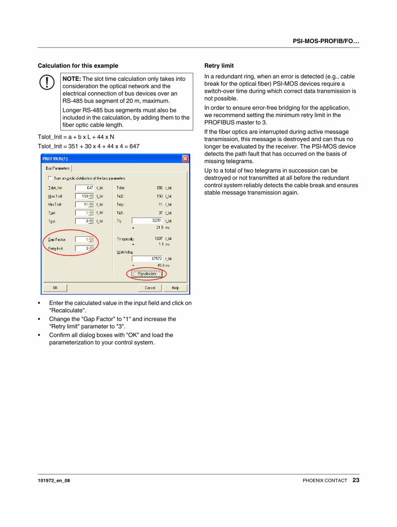
• Click on "Bus Parameters".
PSI-MOS-PROFIB/FO…
101972_en_08 PHOENIX CONTACT 23
Calculation for this example
Tslot_Init = a + b x L + 44 x N
Tslot_Init = 351 + 30 x 4 + 44 x 4 = 647
• Enter the calculated value in the input field and click on
"Recalculate".
• Change the "Gap Factor" to "1" and increase the
"Retry limit" parameter to "3".
• Confirm all dialog boxes with "OK" and load the
parameterization to your control system.
Retry limit
In a redundant ring, when an error is detected (e.g., cable
break for the optical fiber) PSI-MOS devices require a
switch-over time during which correct data transmission is
not possible.
In order to ensure error-free bridging for the application,
we recommend setting the minimum retry limit in the
PROFIBUS master to 3.
If the fiber optics are interrupted during active message
transmission, this message is destroyed and can thus no
longer be evaluated by the receiver. The PSI-MOS device
detects the path fault that has occurred on the basis of
missing telegrams.
Up to a total of two telegrams in succession can be
destroyed or not transmitted at all before the redundant
control system reliably detects the cable break and ensures
stable message transmission again.
NOTE: The slot time calculation only takes into
consideration the optical network and the
electrical connection of bus devices over an
RS-485 bus segment of 20 m, maximum.
Longer RS-485 bus segments must also be
included in the calculation, by adding them to the
fiber optic cable length.

PSI-MOS-PROFIB/FO…
101972_en_08 PHOENIX CONTACT 24
11.2 Configuring the network parameters
(PSI-MOS devices with 8-pos. DIP switch)
Operation in linear, star, and tree structures
In these network structures, use the following formula:
Tslot_Init = a + b x L + 2 x N
Where:
Operation in a redundant ring
In this network structure, use the following formula:
Tslot_Init = a + b x L + 4 x N
Where:
Example
A PROFIBUS DP network with 1.5 Mbps is created using
fiber optics. Four PSI-MOS devices are used in a redundant
ring. The total length of all fiber optic cables is 4 km. To
configure the network parameters, proceed as follows:
• Open the "Properties - DP" dialog box and click on
"Properties".
NOTE: The following configuration instructions
are also valid for the mixed operation of PSI-MOS
devices with 8 and 10-pos. DIP switches.
In this case, set DIP switch 9 (COMPATIBILITY)
to "ON".
Tslot_Init = Minimum slot time in bit periods
a, b = Length parameter (see table)
L = Network expansion in km
N = Number of PSI-MOS devices
Transmission speed
[kbps]
a b
DP DP/FMS
12000 811 811 120
6000 461 461 60
3000 261 261 30
1500 161 991 15
500 111 371 5
187.5 71 371 1.875
93.75 71 211 0.9375
45.45 411 411 0.4545
19.2 71 76 0.192
9.6 71 71 0.096
Tslot_Init = Minimum slot time in bit periods
a, b = Length parameter (see table)
L = Network expansion in km
N = Number of PSI-MOS devices
Transmission speed
[kbps]
a b
DP DP/FMS
1500 311 1971 30
500 211 731 10
187.5 131 731 3.75
93.75 131 411 1.875
45.45 811 811 0.909
19.2 131 141 0.384
9.6 131 131 0.192
NOTE: For PSI-MOS devices with an 8-pos. DIP
switch, the maximum transmission speed in a
redundant ring is 1.5 Mbps.

PSI-MOS-PROFIB/FO…
101972_en_08 PHOENIX CONTACT 25
• Select the subnetwork to be configured and click on
"Properties".
• Switch to the "Network Settings" tab and click on
"Options".
• Switch to the "Cables" tab and activate the "Take into
account the following cable configuration" checkbox.
• Enter the total number of PSI-MOS (OLM) devices used
and the total length of all fiber optic cables.
• Close all dialog boxes with "OK".
• Switch to the "Network Settings" tab and activate the
"User-Defined" profile.
• Click on "Bus Parameters".

PSI-MOS-PROFIB/FO…
101972_en_08 26PHOENIX CONTACT GmbH & Co. KG • 32823 Blomberg • Germany • Phone: +49 - 52 35 - 30 0
PHOENIX CONTACT • P.O.Box 4100 • Harrisburg • PA 17111-0100 • USA • Phone: +717-944-1300
www.phoenixcontact.com
Calculation for this example
Tslot_Init = a + b x L + 4 x N
Tslot_Init = 311 + 30 x 4 + 4 x 4 = 447
• Enter the calculated value in the input field and click on
"Recalculate".
• Change the "Gap Factor" to "1" and increase the
"Retry limit" parameter to "3".
• Confirm all dialog boxes with "OK" and load the
parameterization to your control system.
Maximum ring lengths in kilometers for PSI-MOS
devices with an 8-pos. DIP switch
For PSI-MOS devices with an 8-pos. DIP switch, please
observe the ring lengths in the following table.
For PSI-MOS devices with a 10-pos. DIP switch, there are
no restrictions in terms of ring length if DIP switch 9
(COMPATIBILITY) is set to "OFF".
If DIP switch 9 is set to "ON", the values for the total length
(in km) specified in the table below apply.
Example:
– Number of fiber optic converters in the ring: 6
– Transmission speed: 500 kbps
– Total length permitted according to table: 14.4 km
– Installed total length of fiber optics: 9.98 km → OK
– Use of PSI-MOS devices with an 8-pos. DIP switch
Required slot time:
Tslot_Init = 211 + 9.98 x 10 L + 4 x 6 = 335 bits
Figure 15 Example of a ring installation
NOTE: The slot time calculation only takes into
consideration the optical network and the
electrical connection of bus devices over an
RS-485 bus segment of 20 m, maximum.
Longer RS-485 bus segments must also be
included in the calculation, by adding them to the
fiber optic cable length.
NOTE: When automatic transmission speed
detection is activated, the maximum PROFIBUS
slot time (Tslot) must be 100 ms. If the slot time is
greater, the devices must be configured to the
transmission speed used.
For all PSI-MOS devices with an 8-pos. DIP
switch, there must be at least three devices in the
redundant ring.
Number
of PSI-
MOS
Transmission speed [kbps]
9.60 19.20 45.45 93.75 187.50 500 1500
2 Not permitted
3 9.90 9.90 9.90 9.90 9.90 9.90 5.20
4 13.20 13.20 13.20 13.20 13.20 13.20 5.07
6 19.80 19.80 19.80 19.80 19.80 14.40 4.80
8 26.40 26.40 26.40 26.40 26.40 13.60 4.53
10 33.00 33.00 33.00 33.00 33.00 12.80 4.27
12 39.60 39.60 39.60 39.60 32.00 12.00 4.00
14 46.20 46.20 46.20 46.20 29.87 11.20 3.73
16 52.80 52.80 52.80 52.80 27.73 10.40 3.47
18 59.40 59.40 59.40 51.20 25.60 9.60 3.20
20 66.00 66.00 66.00 46.93 23.47 8.80 2.93
22 72.60 72.60 72.60 42.67 21.33 8.00 2.67
24 79.20 79.20 79.20 38.40 19.20 7.20 2.40
26 85.80 85.80 70.41 34.13 17.07 6.40 2.13
28 92.40 92.40 61.61 29.87 14.93 5.60 1.87
30 99.00 99.00 52.81 25.60 12.80 4.80 1.60
32 105.6 104.17 44.00 21.33 10.67 4.00 1.33
500 kbps


