
Design of 2D Truss Steel Structures
Based on AISC
Eng.Mohammed M. AbuRahma Gaza‐Palestine
2018

Design of 2D Truss Steel Structures Based on AISC
Page(2) Eng.Mohammed AbuRahma
Shapes of Trusses
Design of 2D Truss Steel Structures Based on AISC
Page(3) Eng.Mohammed AbuRahma
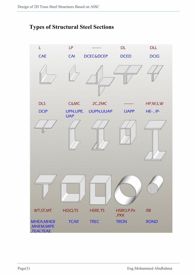
Types of Structural Steel Sections

Design of 2D Truss Steel Structures Based on AISC
Page(4) Eng.Mohammed AbuRahma
Steel structure mainly consist of:
1. Roof Panel. 2. Roof Purlin. 3. Bracing. 4. Gutter. 5. Frame or Truss.
Types of Actions:
1. Dead Load (Own weight) a. Structural elements. b. Roof panel (6 kg/m2) roof thickness = 0.6 mm c. Purlin. d. Bracing.
2. Live Load. 3. Wind Load.

Design of 2D Truss Steel Structures Based on AISC
Page(5) Eng.Mohammed AbuRahma

Design of 2D Truss Steel Structures Based on AISC
Page(6) Eng.Mohammed AbuRahma
Design Example

Design of 2D Truss Steel Structures Based on AISC
Page(7) Eng.Mohammed AbuRahma
Members
Member Group Section Weight (lb./ft) Top Cord 4×4×3/4 18.5
Bottom Cord 3 1/2×3 1/2×1/2 11.08
Diagonal members 3×3×1/2 9.39
Vertical 3×3×3/8 7.17
Purlin C 4 X 7.25 7.25 Bracing members L 3 X 2 X 3/16 3.07 Column W 6 X 20 20
Loads
Dead load
Roof panel weight = 1.22 psf (lb./ft2) (roof thickness = 0.6 mm). Purlin weight = 7.25 lb./ft. Span length=16 ft Metal deck =Area ×wt.= (16× 8) ×1.22=156.16 lb. Purlins= length ×wt.= (16 ×7.25) =116 lb.
Bracing length =2 ∗ 8 4 17.88 Bracing =length ×wt.= (17.88×3.07) =54.91 lb. Dead load = 156.16 + 116 +54.91= 327 lb. Loads at interior joints = D = 327 lb. Loads at exterior joints =D ∕ 2=327 ∕ 2=163.5 lb.
Live Load
According to ASCE 7-10 Table 4-1 Live load =20 psf Live load = 16 8 20 2560 . Loads at interior joints = 2560 .Loads at exterior joints = /2 2560/2 1280 .
Wind Load . / , where
q = velocity pressure (kN/m2)
V = specified basic wind speed (km/m2)
H = roof height above ground (m) (H must be greater than or equal to 4.6 m), (1m = 3.28 ft)
⁄
15.15° 10
13 22 35 10.67 V=120 km/hr. (The maximum velocity in Gaza strip)
2.456 10 120 10.67 / 0.6956 ⁄

Design of 2D Truss Steel Structures Based on AISC
Page(8) Eng.Mohammed AbuRahma
1 0.0478 / .
.14.55
14.55 16 232.83 ⁄ 0.2328 ⁄
14.55 16 8 1862.4 1.8624
1.8624 2⁄ 0.9312
Load combinations
Case 1: Dead Load 1.4 Case 2: Dead Load and live 1.2 1.6
Case 3: Dead Load and wind right 0.9 1.0
Case 4: Dead Load and wind left 0.9 1.0
Case 5: Dead Load and wind right and live 1.2 1.6 0.5
Case 6: Dead Load and wind left and live 1.2 1.6 0.5
Other cases many not be critical
Results of analysis
The table below summarize the result of the most critical design load for each group
Member Group Section Length (ft)Design factored load (kips)
Comp (+) Tension (-) Top Cord 4×4×3/4 8.29 104.14 52.86 Bottom Cord 3 1/2×3 1/2×1/2 8 34.89 100.5 Diagonal members 3×3×1/2 13.47 15.5 9.99 Vertical 3×3×3/8 13 10.03 25.2 Column W 6 X 20 22 30.14 12.47
Design of 2D Truss Steel Structures Based on AISC
Page(9) Eng.Mohammed AbuRahma
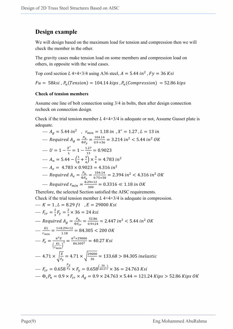
Design example
We will design based on the maximum load for tension and compression then we will check the member in the other.
The gravity cases make tension load on some members and compression load on others, in opposite with the wind cases.
Top cord section 4×4×3/4 using A36 steel, 5.44 , 36
58 , 104.14 , 52.86
Check of tension members
Assume one line of bolt connection using 3/4 in bolts, then after design connection recheck on connection design.
Check if the trial tension member 4×4×3/4 is adequate or not, Assume Gusset plate is adequate.
5.44 , 1.18 , 1.27, 13
.
. 3.214 5.44
1 1 . 0.9023
5.44 4.783
4.783 0.9023 4.316
.
.2.394 4.316
. 0.3316 ≪ 1.18
Therefore, the selected Section satisfied the AISC requirements. Check if the trial tension member 4×4×3/4 is adequate in compression.
1, 8.29 , 29000
36 24
.
.2.447 5.44
.
.84.305 200
.
40.27
4.71 4.71 133.68 84.305
0.658 0.658 . 36 24.763
0.9 0.9 24.763 5.44 121.24 52.86


