
International Journal of Scientific and Research Publications, Volume 3, Issue 12, December 2013 1 ISSN 2250-3153
www.ijsrp.org
Design of a Circuit for Remote Control of Multiple
Devices using DTMF Encoder and Decoder
Haimanti Chakraborty*, Prof. (Dr.) Prabir Banerjee
*
* Department of Electronics & Communication Engineering, Heritage Institute of Technology, Kolkata, India
Abstract- With the advancement in technology, the number
of electronic devices in our day-to-day lives has increased to
make life simpler. So a necessity to construct a Universal
Remote System that will easily control all these devices from a
distance will not only reduce the complexity of handling the
number of devices simultaneously, but also save power.
This paper presents a successfully developed hardware
of a Universal Remote Control System using DTMF (Dual-
Tone Multi-Frequency) tones as the control signals. The
uniqueness of DTMF is that it is simple to generate and noise-
immune. This system was also implemented using GSM links
besides the wired channel, the main advantage of it being that it
helps in controlling devices located at any part of the world or
at any place like hazardous plants, where the presence of a
human could prove dangerous. So there are a number of
practical applications associated with this system. It is simple,
economical, easy to use and could be further upgraded by
adding a password-protection to it. Through this, only selected
people can access control on the devices. A voice-controlled
command could be embedded to make the system more
flexible.
Index Terms- DTMF, IC 91215B, IC CM8870C, Remote
Control Design.
I. INTRODUCTION
n this modern era, life without Electronics is unimaginable.
With the progressive increase in the number of electronic
gadgets, it has become essential to design a remote control
system that can control a number of them at the same time. A
remote control system now finds a large number of crucial
applications like controlling of artificial satellites, manufacture of
products by machines or in the control of chemical reactions in
hazardous plants from a distance.
For the design of a remote control system that will control
the switching of multiple electronic devices at the same time,
DTMF (Dual-Tone Multi-Frequency) tones have been used. The
main reason for the use of DTMF is that one can control a
maximum of twelve (if 3x4 type DTMF keypad is used) to
sixteen (if 4x4 keypad is used) devices simultaneously by means
of a single remote system.
II. BASIC PRINCIPLES OF DTMF
DTMF as stated, is the short form of “Dual-Tone Multi-
Frequency” and it is a method of designating digits with tone-
frequencies that will be transmitted via an analog communication
channel or network like a telephone line. It was developed
by Western Electric and introduced by AT&T in 1963. During its
development, unique individual frequency filters were chosen
carefully so that the tones could easily travel via the telephone
lines (the maximum guaranteed bandwidth for a standard
telephone line extends from around 300 Hz to 3.5 kHz). DTMF
was not intended for data transfer, rather for control signals only.
With a standard DTMF encoder/decoder, it is possible to signal
at a rate of around 10 tones/signals per second.
The DTMF keypad is laid out in a 4x4 matrix, with two
frequencies (each row representing a low frequency and each
column representing a high frequency) played simultaneously by
a standard home phone/fax or mobile phone. Each key on the
telephone’s keypad has a unique frequency assigned to it.
Pressing a single key (such as ‘1’) will send a sinusoidal tone for
each of the two frequencies (697 Hz and 1209 Hz). The multiple
tones are the reason for calling the system as multiple-frequency.
This prevents the misinterpretation of the harmonics and hence, it
is immune to noise. These tone are then decoded by the
switching center to determine which key was pressed. When any
key is pressed on the DTMF keypad, the circuit plays the
corresponding DTMF tone. A typical DTMF keypad is illustrated
in the table below:
Table I: Row and Column Frequencies corresponding to the
digits of the 4x4 DTMF Keypad
1 2 3 A 697
4 5 6 B 770
7 8 9 C 852
* 0 # D 941
1209 1336 1477 1633 Frequencies
(in Hz)
Table I shows us the two frequencies generated when a particular
digit is pressed. The intersection point of any two groups of
frequencies will give us that digit.
In the table that follows, the frequencies generated for all the
digits have been listed.
I
International Journal of Scientific and Research Publications, Volume 3, Issue 12, December 2013 2
ISSN 2250-3153
www.ijsrp.org
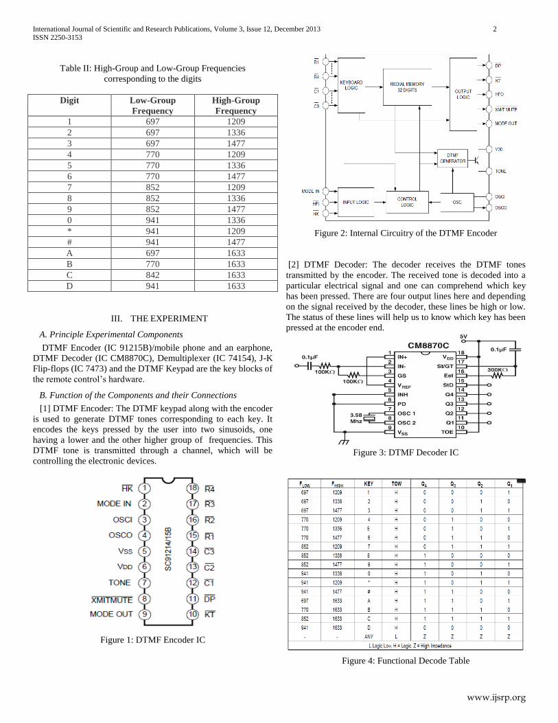
Table II: High-Group and Low-Group Frequencies
corresponding to the digits
Digit Low-Group
Frequency
High-Group
Frequency
1 697 1209
2 697 1336
3 697 1477
4 770 1209
5 770 1336
6 770 1477
7 852 1209
8 852 1336
9 852 1477
0 941 1336
* 941 1209
# 941 1477
A 697 1633
B 770 1633
C 842 1633
D 941 1633
III. THE EXPERIMENT
A. Principle Experimental Components
DTMF Encoder (IC 91215B)/mobile phone and an earphone,
DTMF Decoder (IC CM8870C), Demultiplexer (IC 74154), J-K
Flip-flops (IC 7473) and the DTMF Keypad are the key blocks of
the remote control’s hardware.
B. Function of the Components and their Connections
[1] DTMF Encoder: The DTMF keypad along with the encoder
is used to generate DTMF tones corresponding to each key. It
encodes the keys pressed by the user into two sinusoids, one
having a lower and the other higher group of frequencies. This
DTMF tone is transmitted through a channel, which will be
controlling the electronic devices.
Figure 1: DTMF Encoder IC
Figure 2: Internal Circuitry of the DTMF Encoder
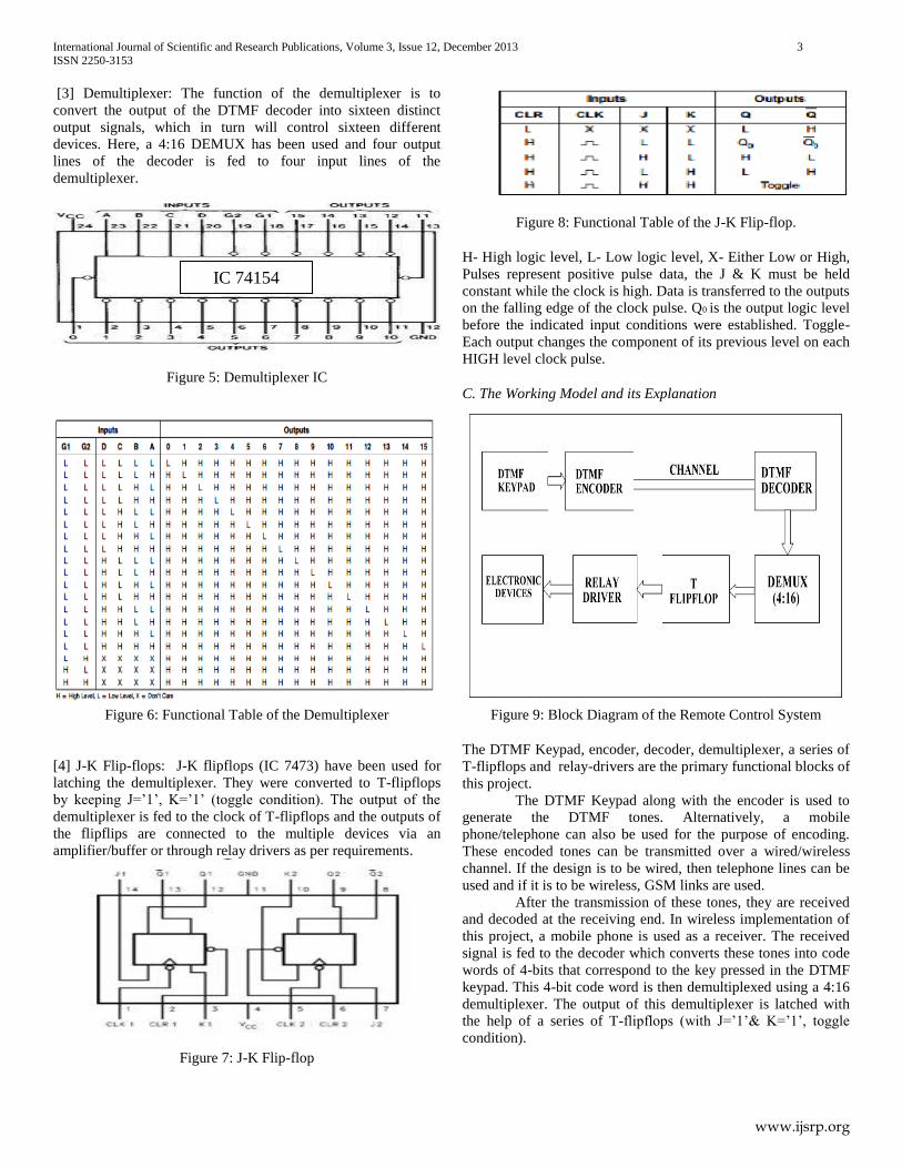
[2] DTMF Decoder: The decoder receives the DTMF tones
transmitted by the encoder. The received tone is decoded into a
particular electrical signal and one can comprehend which key
has been pressed. There are four output lines here and depending
on the signal received by the decoder, these lines be high or low.
The status of these lines will help us to know which key has been
pressed at the encoder end.
Figure 3: DTMF Decoder IC
Figure 4: Functional Decode Table
International Journal of Scientific and Research Publications, Volume 3, Issue 12, December 2013 3
ISSN 2250-3153
www.ijsrp.org
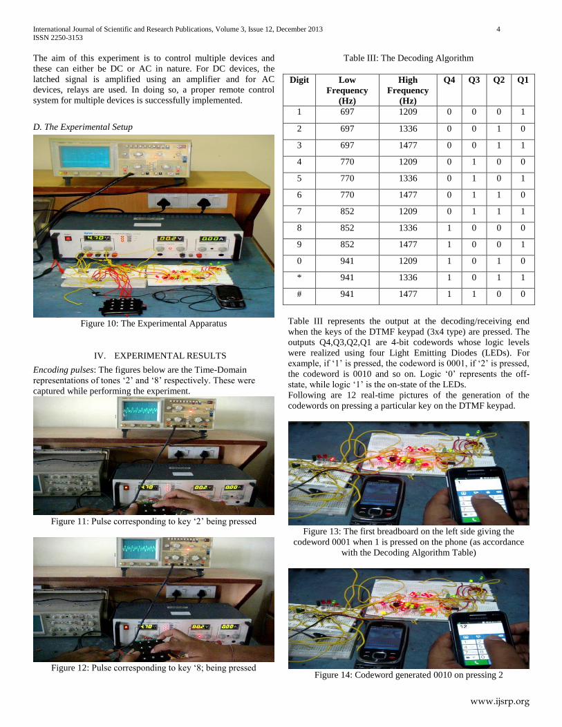
[3] Demultiplexer: The function of the demultiplexer is to
convert the output of the DTMF decoder into sixteen distinct
output signals, which in turn will control sixteen different
devices. Here, a 4:16 DEMUX has been used and four output
lines of the decoder is fed to four input lines of the
demultiplexer.
Figure 5: Demultiplexer IC
Figure 6: Functional Table of the Demultiplexer
[4] J-K Flip-flops: J-K flipflops (IC 7473) have been used for
latching the demultiplexer. They were converted to T-flipflops
by keeping J=’1’, K=’1’ (toggle condition). The output of the
demultiplexer is fed to the clock of T-flipflops and the outputs of
the flipflips are connected to the multiple devices via an
amplifier/buffer or through relay drivers as per requirements.
Figure 7: J-K Flip-flop
Figure 8: Functional Table of the J-K Flip-flop.
H- High logic level, L- Low logic level, X- Either Low or High,
Pulses represent positive pulse data, the J & K must be held
constant while the clock is high. Data is transferred to the outputs
on the falling edge of the clock pulse. Q0 is the output logic level
before the indicated input conditions were established. Toggle-
Each output changes the component of its previous level on each
HIGH level clock pulse.
C. The Working Model and its Explanation
Figure 9: Block Diagram of the Remote Control System
The DTMF Keypad, encoder, decoder, demultiplexer, a series of
T-flipflops and relay-drivers are the primary functional blocks of
this project.
The DTMF Keypad along with the encoder is used to
generate the DTMF tones. Alternatively, a mobile
phone/telephone can also be used for the purpose of encoding.
These encoded tones can be transmitted over a wired/wireless
channel. If the design is to be wired, then telephone lines can be
used and if it is to be wireless, GSM links are used.
After the transmission of these tones, they are received
and decoded at the receiving end. In wireless implementation of
this project, a mobile phone is used as a receiver. The received
signal is fed to the decoder which converts these tones into code
words of 4-bits that correspond to the key pressed in the DTMF
keypad. This 4-bit code word is then demultiplexed using a 4:16
demultiplexer. The output of this demultiplexer is latched with
the help of a series of T-flipflops (with J=’1’& K=’1’, toggle
condition).
IC 74154
International Journal of Scientific and Research Publications, Volume 3, Issue 12, December 2013 4
ISSN 2250-3153
www.ijsrp.org
The aim of this experiment is to control multiple devices and
these can either be DC or AC in nature. For DC devices, the
latched signal is amplified using an amplifier and for AC
devices, relays are used. In doing so, a proper remote control
system for multiple devices is successfully implemented.
D. The Experimental Setup
Figure 10: The Experimental Apparatus
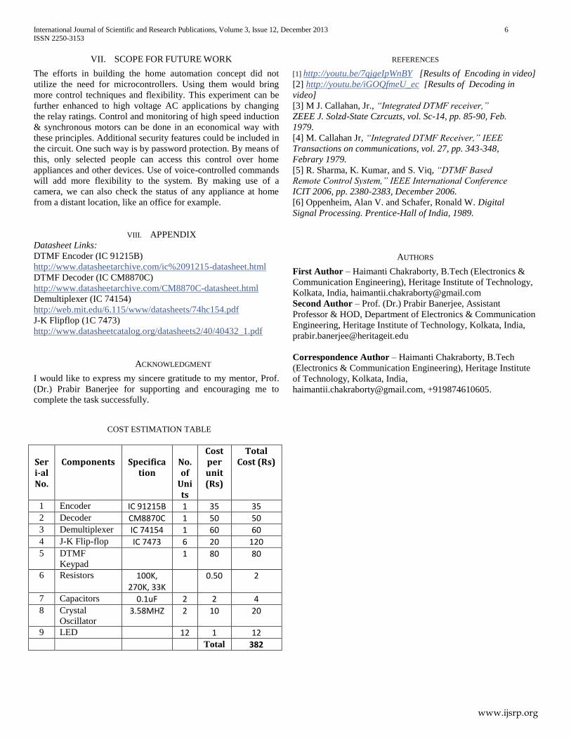
IV. EXPERIMENTAL RESULTS
Encoding pulses: The figures below are the Time-Domain
representations of tones ‘2’ and ‘8’ respectively. These were
captured while performing the experiment.
Figure 11: Pulse corresponding to key ‘2’ being pressed
Figure 12: Pulse corresponding to key ‘8; being pressed
Table III: The Decoding Algorithm
Digit Low
Frequency
(Hz)
High
Frequency
(Hz)
Q4 Q3 Q2 Q1
1 697 1209 0 0 0 1
2 697 1336 0 0 1 0
3 697 1477 0 0 1 1
4 770 1209 0 1 0 0
5 770 1336 0 1 0 1
6 770 1477 0 1 1 0
7 852 1209 0 1 1 1
8 852 1336 1 0 0 0
9 852 1477 1 0 0 1
0 941 1209 1 0 1 0
* 941 1336 1 0 1 1
# 941 1477 1 1 0 0
Table III represents the output at the decoding/receiving end
when the keys of the DTMF keypad (3x4 type) are pressed. The
outputs Q4,Q3,Q2,Q1 are 4-bit codewords whose logic levels
were realized using four Light Emitting Diodes (LEDs). For
example, if ‘1’ is pressed, the codeword is 0001, if ‘2’ is pressed,
the codeword is 0010 and so on. Logic ‘0’ represents the off-
state, while logic ‘1’ is the on-state of the LEDs.
Following are 12 real-time pictures of the generation of the
codewords on pressing a particular key on the DTMF keypad.
Figure 13: The first breadboard on the left side giving the
codeword 0001 when 1 is pressed on the phone (as accordance
with the Decoding Algorithm Table)
Figure 14: Codeword generated 0010 on pressing 2

International Journal of Scientific and Research Publications, Volume 3, Issue 12, December 2013 5
ISSN 2250-3153
www.ijsrp.org
Figure 15: Codeword generated 0011 on pressing 3
Figure 16: Codeword generated 0100 on pressing 4
Figure 17: Codeword generated 0101 on pressing 5
Figure 18: Codeword generated 0110 on pressing 6
Figure 19: Codeword generated 0111 on pressing 7
Figure 20: Codeword generated 1000 on pressing 8
Figure 21: Codeword generated 1001 on pressing 9
Figure 22: Codeword generated 1011 on pressing *
Figure 23: Codeword generated 1010 on pressing 0
Figure 24: Codeword generated 1100 on pressing #
The results have been video recorded and uploaded on Youtube.
The links for the results of encoding and decoding are provided
in the ‘References Section’.
V. APPLICATIONS & ADVANTAGES
[1] DTMF tones can be transmitted over GSM links and hence,
we can control different devices over a large distance
wirelessly.
[2] Effective control of home appliances using mobile phone.
[3] Increases power efficiency and the lifetime of the
appliances..
[4] Power wastage is reduced.
[5] DTMF has enabled the long distance signaling of dialled
numbers in the voice frequency range over telephone lines. This
has eliminated the need of telecom operators between the caller
and called party and evolved automated dialling in the telephone
switching centers.
[6] Use of two frequencies make the system more noise immune.
Hence, DTMF is popularly used.
VI. CONCLUSION & DISCUSSIONS
This experiment was designed keeping in mind the interest of the
common people with the belief that the ultimate outcome of this
project will be of much help to them, making their lives simpler.
It was done using the wireless system and it is
extremely fast and efficient. The DTMF tone can be transmitted
over the GSM links and hence, the basis for the control of
multiple devices from a distance was successfully achieved. This
will help people to regulate the switching of a device situated at a
hazardous place like a chemical plant where the presence of a
human is harmful.
International Journal of Scientific and Research Publications, Volume 3, Issue 12, December 2013 6
ISSN 2250-3153
www.ijsrp.org
VII. SCOPE FOR FUTURE WORK
The efforts in building the home automation concept did not
utilize the need for microcontrollers. Using them would bring
more control techniques and flexibility. This experiment can be
further enhanced to high voltage AC applications by changing
the relay ratings. Control and monitoring of high speed induction
& synchronous motors can be done in an economical way with
these principles. Additional security features could be included in
the circuit. One such way is by password protection. By means of
this, only selected people can access this control over home
appliances and other devices. Use of voice-controlled commands
will add more flexibility to the system. By making use of a
camera, we can also check the status of any appliance at home
from a distant location, like an office for example.
VIII. APPENDIX
Datasheet Links:
DTMF Encoder (IC 91215B)
http://www.datasheetarchive.com/ic%2091215-datasheet.html
DTMF Decoder (IC CM8870C)
http://www.datasheetarchive.com/CM8870C-datasheet.html
Demultiplexer (IC 74154)
http://web.mit.edu/6.115/www/datasheets/74hc154.pdf
J-K Flipflop (1C 7473)
http://www.datasheetcatalog.org/datasheets2/40/40432_1.pdf
ACKNOWLEDGMENT
I would like to express my sincere gratitude to my mentor, Prof.
(Dr.) Prabir Banerjee for supporting and encouraging me to
complete the task successfully.
REFERENCES
[1] http://youtu.be/7qjgeIpWnBY [Results of Encoding in video]
[2] http://youtu.be/iGOQfmeU_ec [Results of Decoding in
video]
[3] M J. Callahan, Jr., “Integrated DTMF receiver,”
ZEEE J. Solzd-State Czrcuzts, vol. Sc-14, pp. 85-90, Feb.
1979.
[4] M. Callahan Jr, “Integrated DTMF Receiver,” IEEE
Transactions on communications, vol. 27, pp. 343-348,
Febrary 1979.
[5] R. Sharma, K. Kumar, and S. Viq, “DTMF Based
Remote Control System,” IEEE International Conference
ICIT 2006, pp. 2380-2383, December 2006.
[6] Oppenheim, Alan V. and Schafer, Ronald W. Digital
Signal Processing. Prentice-Hall of India, 1989.
AUTHORS
First Author – Haimanti Chakraborty, B.Tech (Electronics &
Communication Engineering), Heritage Institute of Technology,
Kolkata, India, [email protected]
Second Author – Prof. (Dr.) Prabir Banerjee, Assistant
Professor & HOD, Department of Electronics & Communication
Engineering, Heritage Institute of Technology, Kolkata, India,
Correspondence Author – Haimanti Chakraborty, B.Tech
(Electronics & Communication Engineering), Heritage Institute
of Technology, Kolkata, India,
[email protected], +919874610605.
COST ESTIMATION TABLE
Seri-al No.
Components
Specifica
tion
No. of
Units
Cost per unit (Rs)
Total Cost (Rs)
1 Encoder IC 91215B 1 35 35 2 Decoder CM8870C 1 50 50 3 Demultiplexer IC 74154 1 60 60 4 J-K Flip-flop IC 7473 6 20 120 5 DTMF
Keypad 1 80 80
6 Resistors 100K, 270K, 33K
0.50 2
7 Capacitors 0.1uF 2 2 4 8 Crystal
Oscillator 3.58MHZ 2 10 20
9 LED 12 1 12 Total 382


