
!
.·
•
Designing A Radiolo~y Workstation: A Focus on N avigatlon During the
Interpretation Task TR89-040
December, 1989
David V. Beard
Medical Image Display Group Department of Computer Science D epartment of Radiation Oncology D epartment of Radiology
The U niversity of North Carolina Chapel Hill, NC 27599-3175
UNC is an Equal Opportunity/ Affirmative Action Institution.

Designing a Radiology Workstation:
A Focus on Navigation During
the Inte~pretatbn Task.
David Beard,Ph.D
Research Assistant Professor of Radiology
Adjunct Assistant Professor cf Computer Science
University of North Carolina
Chapel Hill, NC. 27514
This work was supported by NTH grants ROl CA 44060 and POl CA 47982.
1

2
ABSTRACT
The potential cost and logistic improvements of PACS (Picture Archive and Communication Sys
tem) over film-based medical image management awaits the development of viable radiology work
stations (RWS) targeted for the primary interpretation task. While the quality of electronically dis
played images has been highly investigated, only recently has design and experimental work been
devoted to the other critical aspect of RWS design, mainly its computer human interaction, and in
particular, its navigation. By RWS navigation we include its underlying mental model or metaphor,
and the commands and hand motions used to access patient folders and to display images.
For the last five years, the University of North Carolina Medical Image Display Research Group has •
analyzed the primary interpretation task and designed, developed, and evaluated the FilmPlane series
of radiology workstation prototypes. This work has helped us understand both radiology worksta
tion requirements and viable design approaches. In this paper, we describe the issues and problems
with RWS navigation and present the objectives and design of FilmPlane2 as well as our human
computer interaction strategy. We also detail three rapid evaluation techniques for quickly gaining
feedback on a design. These techniques may aid other radiology workstation designers.
Keywords: computer human interaction, radiology workstations, human factors, medical image
display.

3
1 INTRODUCTION
Designing an acceptable computer-human interaction (CHI) is art rather than science. Nevertheless,
a general methodology has been widely adapted that allows for the rapid evolution toward a viable
product [1]. First, a well designed em starts with a complete task analysis including an understand
ing of the users and their tasks. Second, a clear mental model or metaphor must be developed which
allows the user to understand quickly the workstation operation. Third, the complete interaction
must be carefully designed and implemented. Founh, various subject experiments, observation ses
sions, and time-motion analysis techniques must be used to refme the workstation into a viable tool.
Designers must remember that as toolmiths, their objective is to develop a productive tool for the
users. In the final analysis, "the quality of a swonismith is measured by the longevity of his cus-
tomers" [2]. '
First, the radiology interpretation task is described. Second, workstation design issues are dis
cussed. Third, the design of FilmPlane is presented including objectives, mental models, direct
manipulation interaction, image navigation, display-area requirements, and response-time require
ments. Fourth, a series of experiments are described which were used to evolve FilmPlane. These
experiment designs may prove useful to other workstation designers.
2. RADIOLOGY WORKSTATION TASK ANALYSIS
W orlcstation design must be based on a clear understanding of tasks performed with film and view
box, including both projection radiographs and multiple cross-section digital studies such as cr [3,4]. During the interpretation task, the radiologist views the images resulting from the radiology
procedure, and together with other information (patient history, images from previous procedures,
input from the referring physician, etc.), interprets the images for the referring physician. The pri
mary interpretation task is typically performed on either a "four over four" viewbox array, or an
"alternator", a device which stores the films on a large horizontal strip of clear plastic which is me
chanically moved over a row of four viewboxes, alternating which four films are displayed (see
Figure 1 ). Smaller viewbox configurations are used for viewing single studies.
There is large variation in the amount of film to be viewed for an interpretation, ranging from a sin
gle 14"x17" plain radiograph to a complex case involving several multi-image, cross-sectional-slice
cr or MR studies with hundreds of images arrayed on thirty or more films. The possible permuta
tions of images for an interpretation are too large to enumerate, but our research has led us to focus

4
on two classes of interpretations: those involving two or mc•rr time· separated CT studies of the same
body area and interpretations involving severall4"x17" radiograph,. We believe that a workstation
design that is viable for these two classes of interpretauons should be adaptable to most others.
Figure I
Alternator with
Multiple CT studies
A successful interpretation requires text as well as image information. The requisition form details
the medical questions the referring physician wants the radiology procedure to answer; these medical
questions greatly affect the search patterns the radiologist uses when viewing the images [8]. The
radiology procedure date, slice thickness, type of radiologic device, the name of the technician that
performed the procedure, whether contrast was administered, etc. is provided. The radiology infor
mation system (RIS) provides patient information. Finally, the interpretation reports generated from
previous radiology studies are (ideally) available.
2.1 Image Scan Patterns
The following details how radiologists view medical images. At UNC, we have used an Eyemark
EMR-V eyetracker to study interpretation of one class of critical patient folders: those containing sin
gle and multiple CT chest studies 151. An eyetracker determines the position of a subject's eyes, and
superimposes markers corresponding to these positions on a video signal, generated from a camera
mounted in front of the forehead on the eyetracker helmet, and directed to monitor and recorder.
This provides the experimenter with a recording of both the subject's field of view and eye posi-

5
lions. The Eyernark EMR-V allows subject head and body movement. making it particularly useful
for analyzing medical image interpretation.
The follow'.illg search pattern has been found to occur generally during interpretation of a single cr study: first, images are removed from the patient folder, soned, and some of the ftlms are placed
onto the viewbox. Images are viewed during this viewbox loading process. In some institutions,
this step is performed by the technologist, but a large number of radiologists seem to prefer to load
the films themselves. Second, a systematic search pattern is performed over all the images.
Sometimes this is by organ, but in general, a systematic sequential scan pattern is initially
used to view the slices in a multiple slice study.
This sequential pattern often occurs first through the images intensity-windowed for the medi-'
astinum, followed by sequential review of the images intensity windowed for the lungs. (Intensity
windowing is a contrast adjustment technique used to allow viewing of different density anatomy. It
is described in more detail shortly.) Little or no cross comparison between images of different in
tensity windowing occurs. Third, critical slices showing imponant anatomy are reviewed in detail.
Fourth, an interpretation repon is dictated, often while continuing to view the images. Fifth, the
films are removed from the viewbox and replaced, often in a random order, back into the patient
folder.
A great deal of time is spend locating and accessing small clusters of images that show imponant
anatomy. An image cluster is identified when a radiologist repeatedly fixates on the same proximate
images. When asked how much of the patient's folder radiologists need to view simultaneously,
they typically answered "all of it"[ 6,7]. However, based on our eye movement studies, radiologists
only seem to view small localities of reference, that is, small clusters of typically one to four cr images. But radiologists are not ineotrect in feeling they need to have all of the patient folder simul
taneously displayed. The remaining images appeared to be used as a pictorial image index, al
lowing the radiologist to locate quickly any particular image.
With patient folders containing multiple studies the search patterns are more complex. Generally ra
diologists first read the requisition form and possibly one or more interpretation repons. Second,
they arbitrarily access critical slices in the previous study, and sequentially view the current study;
the order of these tasks often is reversed. Third, radiologists often compare clusters of images
from the current study to clusters from previouSoones to determine whether an anatomical object is
abnormal, or whether it had increased or decreased in size. Since radiologists need to compare
anatomical objects which occupy many cr slices, this can be a complex task. Typically clusters of

6
one to four image~ are cross-compared, even if the anatomical objects occupy a larger number of
slices. Radiologists sometimes rapidly move their eyes back and forth between the clusters, and at
other times slowly examine the fJI'St cluster followed by the second. Comparisons are also done
between studies of different modalities (imaging techniques such as cr or radiography) to improve
anatomical understanding. When there are symmetries around a vertical center axis, radiologists
often compm: the left and right sides to aid in locating abnormalities.
If the patient folder contains no more than eight films, the typical "four over four" viewbox is an ef
fective tool for viewing medical images. But for more complex cases, a patient folder may contain
more films than available viewbox space. While the alternator is an improvement, it does not solve
the problem Films must either be left in piles on nearby tables, or double stacked on several view
boxes. Time is wasted locating and moving films. A great deal of frustration is generated. . Others have recorded eye movements of radiologists reading medical images [8,9,6], though most
of this resean:h was for determining source of interpretation errors, rather than developing task
analyses. Experienced radiologists employ a variable, though basically circumferential, scan pattern
when reading radiographs [ 1 0]. Search patterns develop with experience [11], are affected by prior
knowledge [8], and deviate from textbook recommendations [9]. While some studies have sug
gested that misreadings (false negatives which range around 30% [12,13,14]) may occur because
large areas of film are not foveally viewed (viewed with the fovea area of the retina which affords
acute vision) [15], or because there is non-uniform coverage of the film [16], eyetracking experi
ments indicate that only about 30% of missed lung nodules can be attributed to the lesion not having
been foveally viewed [17]. More recently, studies have been initiated to determine woootation re
quirements for interpreting single small radiographs [ 18,19].
2.2 Advanced Tools
Visually comparing images from different studies is difficult,though necessary to determine changes
in the size of anatomy. Tools that help radiologists determine the size of anatomical objects reduce
the amount of visual comparison. One dimensional measuring tools are useful. Tools that accu
rately measure the volume of anatomical objects in multiple-slice studies would be even more bene
ficial. Radiologists currently measure the size of anatomical objects manually or with the cr or MR
machine's console.
Several new techniques allow reconstruction of multiple slice cr or MR studies into three dimen
sional pictures of anatomical features [20]. These three dimensional pictures appear to be particu-

7
larly useful for understanding complex spatial structures such as intricate bone fr.tctures. Advanced
volume rendering techniques [21] are particularly good for viewing 'b6ne, but also may be used on '1!!'->,_
soft tissue. While current three dimensional volume rendering techniques do not produce sufficient
image quality to serve as the only view of a study's images during the interpretation, such render
ings can serve an important auxiliary role, and eventually should be incorporated into a viable two
dimensional image-viewing workstation.
2.7 Image Quality and Contrast Adjustment
Any viable radiology worlcstation must have adequate image quality. To display an image, the sys
tem must have adequate values for screen size, number of pixels, gray-scale dynamic range, number
of digital intensity levels, and should be standardized so that a gray-scale value produces the same
luminance regardless of the screen on which it is displayed. Theoretical calculations '[22] indicate
that radiographs require a sampling of 4ooo2 16-bit pixels to capture their full resolution. Anecdotal
reports by radiologists revealed that pneumothorax pleural lines on chest x-rays that have been digi
tized at 2000 lines were seen well only when the image was displayed at that resolution, and that
these same pleural lines were discernible at lesser resolution only if edge enhancement processing
were performed. Controlled studies, e.g. [23,24,25], have confirmed the need for at least 20()()2
pixel display of radiographs, and in some cases, 400()2.
Contrast enhancement or intensity windowing creates an image focused on presenting a particular
anatomy; it is almost essential for the electronic display of medical images[26,27 ,28]. Such contrast
adjustment allows details of the very dense bone, and details of soft tissue to be available from the
same slice. When intensity windowing an image, the radiologist chooses a window of a certain
width from the entire total range of contrast in the cr or other digitally produced image, and then
places this window at a certain level in the total cqntrast range. If a given pixei value faJJs within this
window, it is translated into a corresponding pixel value in the (typically) eight-bit framebuffer.
Pixel values outside the window are set at 0 or 1 respectively. Image processing such as contrast
limited adaptive histogram equalization (CLAHE) and unsharp masking are also very useful.
Overviews may be found in [4] and [29]. Discussion of detailed topics also can be found in
[30,31 ,32,33].
Multiple film images frequently must be made from the same digital slice in order to allow for view
ing the image at multipl~ contrast levels. One critical advantage of a workstation over film is dy
namic contrast adjustment, that is, the ability to change dynamically the window width and level
(WWL) used to display an image. While radiologists need the ability to select all possible intensity

8
windows, most often a selection from a small standard set of WWLs refined for bone,lung, soft tis
sue, brain, etc. is preferred. With a press of a button, the radiologist can rapidly change the contrast
range of a displayed image. Since multiple images, displaying intensity windows for bone, lung, etc
required for film, are not necessary, fewer separate images are needed to convey the same informa
tion [4].
3. FILMPLANE
3.1 Design Objectives
Producing a workstation with acceptable navigation is difficult. The typical viewbox array can
easily display over 64 megabytes of images which the physician can quickly access using techniques •
-- the movement of eyes and head - which have been practiced for an entire professional career.
Even the best workstations barely have this much real memory,let alone display area. Further, the
cognitive motor skill requirements of the viewing task create additional technical complexities for
workstation design.
We concentrated on several critical navigational tasks when developing and evaluating FilmPlane:
Image location for locating any image in the patient folder, arbitrary-access: for displaying and
viewing the images, and sequential access: for moving through slices and for roaming within a ra
diograph. Side-by-side comparison: is also needed to compare various images from one study with
images from another or for comparing one side of a chest radiograph with the other. Our goal is to
develop a workstation prototype upon which a radiologist can conduct an interpretation with quality
equal to that of fllm and viewbox, and in equal or less time. We feel that the radiologist should be
able to conduct a simple interpretation after only five to ten minutes of training. Developing a radi
ology workstation viable for the primary interpretation is very diftlcult, and while the FllmPlane de
sign looks promising, it may prove insufficient for the task, particularly for viewing and comparing
images from many different multiple cross-section studies. Controlled subject experiments are being
designed to determine FilmPlane's viability.
The original version of FilmP!ane used a single 1024x900 pixel display, but we are currently im
plementing the FtlmPlane2 prototype on a Stellar high performance graphics workstation which
uses three 1280x1024 displays. FilmPlane2 will also operate on a Sun 3/&J with a single greyscale
monitor. The current design can be adapted quickly to operate with a varying number of 10242,
20482, or even larger displays.

3.2 Mental model
Detail View
Figure 2
Radiogrnphs
Navigational View
Navigation View, Detail View, and Viewport
9
A key objective of computer human interaction (Cill) is for the user to obtain an understanding of
the computer tool by developing a mental model of its operation [34,35,36,37 ,38,39,40]. Such a
mental model is critical, for it not only allows users to quickly perform tasks, but it also helps them
feel more "in control" of the computer. Developing and teaching an arbitrary mental model of a
complex tool is difficult and frustrating. As an alternative, a mental model of a real-world tool, such
as a desk top or the radiologist's viewbox, can be used as a metaphor for the operation of the com
puter tool. Thus, as long as the computer tool stays within the bounds of the metaphor, the user
will, a priori, understand its operation. Basing computer-tool operation on a metaphor is particularly
useful when designing for non-computer specialists, especially when that tool must be use after only
minimal training.
FilmPlane's operation is based on the metaphor of a two-dimensional navigation view upon which
all the images in the patient folder are systematically arrayed in two, four, or more column strips( see
figure 2) [ 41]. In the navigation view, these columns are arranged horizontally and ordered by time.
A 1 OW pixel image of this navigation view is provided to the user to reinforce the metaphor, with
the medical images displayed at a fraction of their full resolution. Times and dates for each study are
provided. . This index can either be permanently displayed or only appear on command The perma
nent display of the navigation view reinforces its metaphor to the user and eliminates the cognitive
10
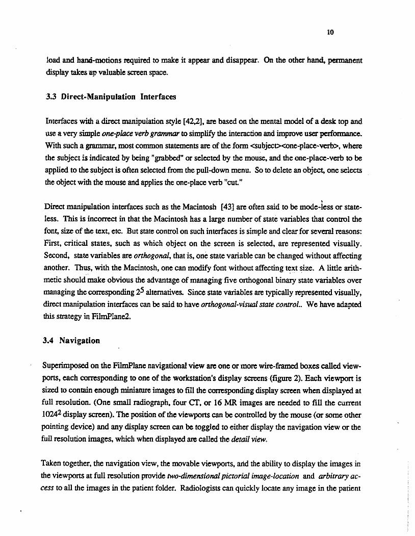
load and hand-motions required to make it appear and disappear. On the other hand, permanent
display takes up valuable screen space.
3.3 Direct-Manipulation Interfaces
Interfaces with a direct manipulation style [ 42,2], are based on the mental model of a desk top and
use a very simple one-place verb grammar to simplify the interaction and improve user perfonnance.
With such a grammar, most common statements are of the fonn <subject><one-place-verb>, where
the subject is indicated by being "grabbed" or selected by the mouse, and the one-place-verb to be
applied to the subject is often selected from the pull-down menu. So to delete an object, one selects
the object with the mouse and applies the one-place verb "cut"
• Direct manipulation interfaces such as the Macintosh [43] are often said to be mode-less or state-
less. This is incorrect in that the Macintosh has a large number of state variables that control the
font, size of the text, etc. But state control on such interfaces is simple and clear for several reasons:
First, critical states, such as which object on the screen is selected, are represented visually.
Second, state variables are onhogonal, that is, one state variable can be changed without affecting
another. Thus, with the Macintosh, one can modify font without affecting text size. A little arith
metic should make obvious the advantage of managing five orthogonal binary state variables over
managing the corresponding 25 alternatives. Since state variables are typically represented visually,
direct manipulation interfaces can be said to have onlwgonal-visual state control.. We have adapted
this strategy in FilmPiane2.
3.4 Navigation
Superimposed on the FilmPiane navigational view are one or more wire-framed boxes called view
ports, each corresponding to one of the workstation's display screens (figure 2). Each viewport is
sized to contain enough miniature images to fill the corresponding display screen when displayed at
full resolution. (One small radiograph, four cr, or 16 MR images are needed to fill the current
10242 display screen). The position of the viewports can be controlled by the mouse (or some other
pointing device) and any display screen can be toggled to either display the navigation view or the
full resolution images, which when displayed are ca1led the detail view.
Taken together, the navigation view, the movable viewports, artd the ability to display the images in
the viewports at full resolution provide two-dimensional pictorial image-location and arbitrary ac
cess to all the images in the patient folder. Radiologists can quickly locate any image in the patient

11
folder by scanning the navigation view. They can quickly display any arbitrarily-selected image by
moving the cursor to a viewport, selecting the viewport by depressing the mouse button, dragging
the viewport to a new location, and releasing the mouse button. These actions cause the images in
the viewport to be displayed at full resolution on the corresponding display (figure 3).
Control Panel
Viewport for Left Display
Viewport for Right Display
Figure 3
Navigation/Detail View Toggle Button
Any of the Three Displays can be Toggled to
Display Either the Detail or the Navigation View.
Two alternatives to a pictorial image index have been constructed. The Arizona workstation [44]
provides image location using a text listing of all the studies in the patient folder and images in each
study. Text image-indexing is acceptable for locating studies consisting of a few large images, each
having clear text-labels such as "chest, 20Jul89". However, we suspect that for experienced radiol
ogists accessing several multi-slice cr studies containing 40 or more slices, no text label will worlc:
as well as the images themselves in indicating contents.
A second alternative to a pictorial index is an icon index [18] in which a simple icon of the body is
used to represent and access the contents of the patient folder. An experiment described in the above
citation indicates that icon indexing may be superior to text indexing. While no comparison between
pictorial and icon indexing has been' undertaken, we speculate that an icon index would be superior
to a pictorial index, such as FilmPiane's navigation view, for inexperienced users who can not in-

12
stt.ntly determine the modality and represented anatomy of a medical image. But for typical experi
enced radiologists, we expect the navigational view to be advantageous. Not only do the miniature
medical images themselves serve as icons denoting general represented anatomy, but their relative
time ordering and the exact size and coverage of each study are available at a glance.
Navigational View Detail View Figure 4
FilmPlane Alternate Display Screens
Radiologists hold their fingers on viewbox-displayed images to provide a visual and tactile reference
[5] thus speeding access. FilmPiane allows radiologists to quickly mark critical images, causing a
bright border to be displayed. Such markers not only allow the radiologist to locate critical images
more quickly, but also tell the computer system which images are imponant to the radiologist allow
ing improved memory management. Some radiologists have also suggested a tool for moving
viewports quickly to one of several standard locations within a typical molt-slice study.
Radiologists often wish to view images near the ones currently being viewed, either by roaming
around on a radiograph that is too large to completely display at full resolution, or by sequentially
moving up or down through a multiple-slice cr or MR study. In particular, it is important that the
interaction be optimized for long strings of sequential movement in the same direction; this often oc-c
curs when the radiologist is sequentially viewing a multiple-slice study. To facilitate sequential
13
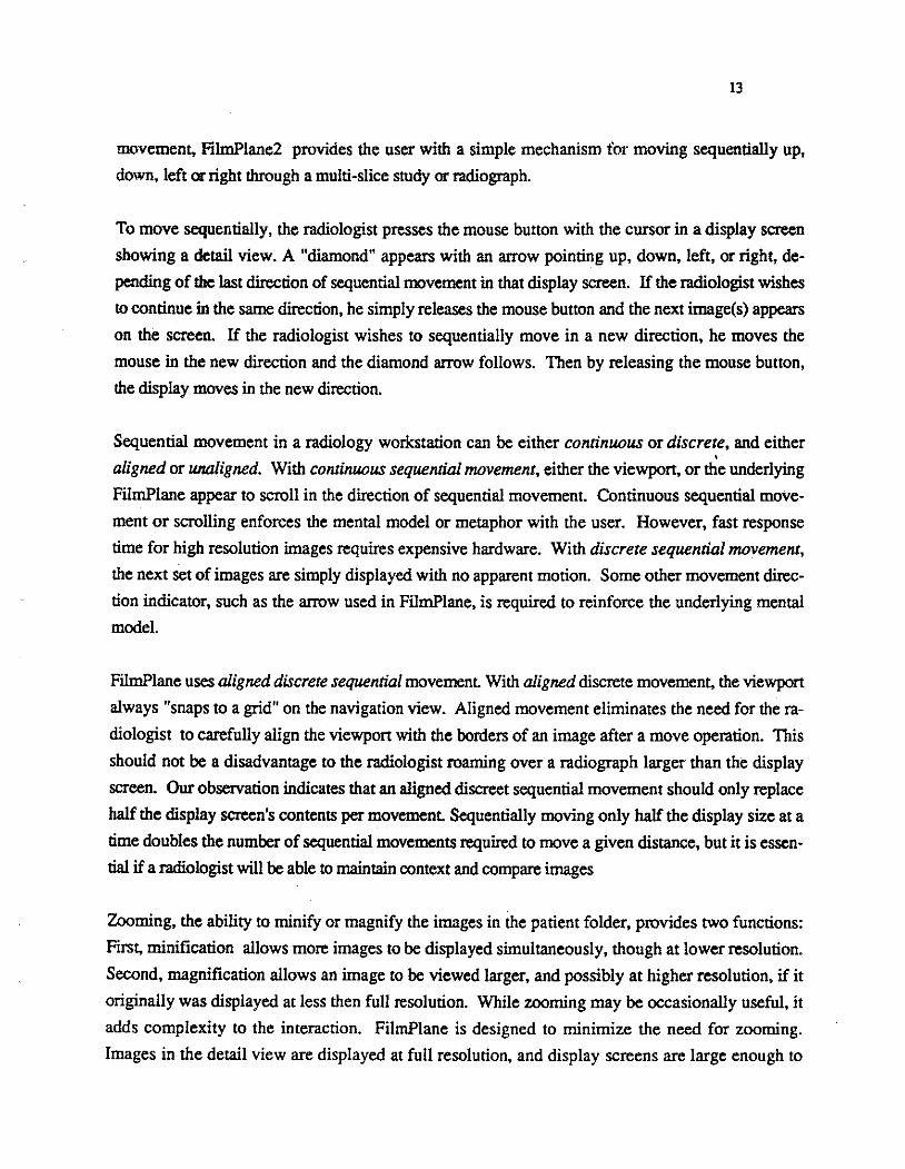
movement, FilmPlane2 provides the user with a simple mechanism for moving sequentially up,
down, left or right through a multi-slice study or radiograph.
To move sequentially, the radiologist presses the mouse button with the cursor in a display screen
showing a detail view. A "diamond" appears with an arrow pointing up, down, left, or right, de
pending of the last direction of sequential movement in that display screen. If the radiologist wishes
to continue in the same direction, he simply releases the mouse button and the next image(s) appears
on the screen. If the radiologist wishes to sequentially move in a new direction, he moves the
mouse in the new direction and the diamond arrow follows. Then by releasing the mouse button,
the display moves in the new direction.
Sequential movement in a radiology workstation can be either continuous or discrete, and either •
aligned or unaligned. With continuous sequential movement, either the viewport, or the underlying
FilmPlane appear to scroll in the direction of sequential movement. Continuous sequential move
ment or scrolling enforces the mental model or metaphor with the user. However, fast response
time for high resolution images requires expensive hardware. With discrete sequential movement,
the next set of images are simply displayed with no apparent motion. Some other movement direc
tion indicator, such as the arrow used in FilmPlane, is required to reinforce the underlying mental
model.
FilmPlane uses aligned discrete sequential movement. With aligned discrete movement, the viewport
always "snaps to a grid" on the navigation view. Aligned movement eliminates the need for the ra
diologist to carefully align the viewpon with the borders of an image after a move operation. This
should not be a disadvantage to the radiologist roaming over a radiograph larger than the display
screen. Our observation indicates that an aligned discreet sequential movement should only replace
half the display screen's contents per movement Sequentially moving only half the display size at a
time doubles the number of sequential movements required to move a given distance, but it is essen
tial if a radiologist will be able to maintain context and compare images
Zooming, the ability to minify or magnify the images in the patient folder, provides two functions:
First, minification allows more images to be displayed simultaneously, though at lower resolution.
Second, magnification allows an image to be viewed larger, and possibly at higher resolution, if it
originally was displayed at less then full resolution. While zooming may be occasionally useful, it
adds complexity to the interaction. FilmPlane is designed to minimize the need for zooming.
Images in the detail view are displayed at full resolution, and display screens are large enough to

14
eliminate the need for zooming merely to increase the size of an image. FilmPlane does provide a
tool that allows the images in a study to be displayed at half resolution.
3.5 Comparing Two Studies
Radiologists often need to compare two or more studies in a patient folder to complete an interpreta
tion. With multiple slice studies such as CT, the radiologist typically views two studies side-by
side comparing corresponding slices of the studies, sequentially moving through both studies at the
same time. This is one of the most difficult tasks to be performed on a radiology workstation. Not
only are many handmotions involved, but a great deal of judgement and effort is required to insure
that the same anatomy from the two studies is compared. Multiple cross-section studies may have
slices taken at different intervals requiring, for example, ten slices from one study to be compared •
with six from another. Further, technologists often backup the CT machine and re-scan the same
body area, so that the same study may contain multiple slices of the same anatomy. If the worlcsta
tion knows the slice intervals of each study and offsets of each slice, it can automatically increment
the displays so that the same anatomy from each study is always viewed. Eventually, CT machines
should digitally encode into each cross-section study file the slice thickness, interval size, and the
mm. offset of each slice from the starting position. Until then the technologists should (ideally) en
ter this information into the PACS system manually.
To side-by-side compare two studies with FilmPlane, the radiologist places a viewport for one dis
play screen at the beginning of one study, and the viewport of a second display screen over the sec
ond study. Then by sequentially moving each viewport downward, the corresponding anatomical
regions of the studies are compared. Viewport may be split-in-two and each half independently
navigated. While this method does allow side-by-side comparison of two multiple slice studies, it
requires a considerable number of hand-motions; the radiologist must first move the cursor to one ·
viewport and sequentially move it down, then move it to the second and move it, and then back to
the flrSL To compare two studies each containing 40 slices would require almost three minutes just
to complete the required hand-motions [45]. To reduce the required number of hand-motions, Film
Plane2 allows the radiologist to connect viewpons; the radiologist need only move one viewport to
move the other. Synchronization is indicated by a white line connecting the two viewpons in the
navigation view. The synchronized viewports will automatically track the same anatomy because
F!lmPlane takes into account the slice intervals of the studies.

15
3.6 Display area
Display area refers to the number of pixels that can be displayed simultaneously. It is difficult to
determine how much display area is sufficient for a primary interpretation workstation. The four
over-four viewbox, with 8000x4000 pixels (eight 2ooo2 radiographs) might be taken as a starting
point, but even its large display area is often insufficient for very large patient folders with many
films. [5] indicates that most of the images placed on the viewbox serve as a pictorial index into the
patient folder, and that far fewer images are actually needed for simultaneous viewing. But how
much display area for a workstation is sufficient?
While roaming and zooming is possible, full resolution display of images is superior. Therefore
20482 monitors (the generally accepted minimum resolution for large radiographs [4)) are neces
sary, and at least two are needed if multiple films are to be compared. More than two 20482 moni
tors may be useful, but since only two studies are generally compared at a time, additional monitors
may not be needed with well-designed navigation and very-fast response time. 10242 monitors are
acceptable if only smaller images are to be viewed. Based on [5] we believe that a display area ca
. pable of showing at least eight CT images is required for multiple CT study interpretations. This
amount of display area is available with several 10242 monitors. Note that these side-by-side com
parisons often can be conducted with images displayed at less than full resolution, possibly reducing
the required display area. A large display area is available either using a smaller number of the
largest available screens, or a larger number of small ones. All else being equal, larger screens are
superior because a large array of small screens is really an inflexible single screen crisscrossed with
big ugly lines.
[19] considers the: possibility of comparing images displayed in sequence rather than side-by-side.
A preliminary experiment is described involving non-radiologists and non-medical images, that
indicates little or no difference between these two methods, besides the time to change the display.
Sequential comparison does reduce by 50% the amount of required display area, but it is not clear
whether the additional cognitive load sequential viewing imposes on the radiologist is prohibitive.
Until more definite studies are completed, we will continue to assume the side-by-side comparisons
are required.
Display size refers to the total square feet of all the display screens. We believe the. four-over-four
viewbox at about 3'x5' represents a reasonable outer-bound on the total square footage that can be
used for display without strain.

16
3. 7 Response time
Sufficiently fast response time is critical to a primary interpretation workstation" This is particularly
true for interpretations that requite viewing multiple-slice studies with many sequential movements"
Slower response time not only increases the total interpretation time, but also causes frustration and
increases cognitive load" Our obsezvations [41,45] indicate that for common operations such as
roaming or moving to the next slice in a cr study, a response time of 1 second is acceptable, with
improvements down to 0"5 seconds or more having a significant effect on total interpretation time"
Several radiology workstation research groups have reponed success with slower response times,
but these research effons appear to be confined to interpretations of radiographs, which involve a
small number of large images, with a correspondingly small number of movement operations . •
Work by [46] and others indicates that consistency in response time may be as critical as absolute
speed, for if the system first takes one second to respond and then 12, users may become frustrated
or think they have damaged the workstation" Given the cost of main memory, a sizable ponion of
the patient folder may need to be stored in the swap space ponion of vinual memory in a radiology
workstation. This may cause wildly varying response times as images are moved in from disk. The
generally accepted solution is to display a "wait" icon such as a hourglass [47] or watch [43] when
ever the system response is delayed. For long delays such as waiting for a patient folder to be
moved from the archive to the workstation, a rough estimate of the response time should be pro
vided.
4. IMPLEMENTATION
FilmPlane2's interaction design, allowing any screen to access any ponion of the image space, pre
sents two difficult-to-achieve requirements: a very large image memory, and the ability to move
rapidly any image from that memory to any screen's framebuffer. Radiology workstation memory
often needs to contain over 60MB of images; cost prohibits using this much main memory. We
have found that vinual memory can be an effective alternative when three requirements are met: first,
there must be sufficient main memory to store a minimum of 16MB for a single screen workstation.
Second, the disks must be fast. Thitd, there must be function to anticipate which images will be
displayed next, and to insure these images are pre-fetched into main memory from disk.
Moving images from vittual memory into the framebuffers with sufficient speed can be very diffi
cult, particularly for the single-bus workstations typically used to implement radiology workstations.

17
We suspect Iii& eventually (five or more years) PACS image management will be implemented with
very high speed networks such as HSC (High Speed Channel) or BISON (Broadband Integrated
Services Digiaai Network) providing a sustained 150 megabits per second to each framebuffer in the
workstation from a very high-speed central archive. A multi-screen FilmPlane2 can be implemented
with current u:c!mology, at a high cost, by either increasing the main memory to framebuffer transfer
rate, or greatl}' increasing the size of the each framebuffer.
For the above reasons, most current commercial radiology workstations use separate image memo
ries for each display screen; thus a multi-screen workstation is a simple concatenation of several
single screen consoles. Such an approach is likely to add complexity to the computer human inter
action, but may be required for cost-effective implementation with today's technology.
5. RAPID EVALUATION OF RWS NAVIGATION DURING DEVELOPMENT
We have utilized two response-time experiments- described below- as well as time-motion analy
sis to quickly compare and evaluate workstation navigation [ 41 ,45]. They are designed for very
rapid evaluation of a navigation technique or tool and only require a minimal amount of radiologist
time. Both experiments use patient folders containing several multiple-slice studies as their interpre
tation is a very challenging navigation task. These evaluation methods may prove useful during ra
diology workstation development
5.1 Experiment One
The first experiment determined the effectiveness of FilmPlane's arbitrary movement and pictorial
image index vs. film and viewbox, by comparing response times for radiologists locating anatomical
targets or landmarks in four patient folders, each containing two abdomen cr studies.
Methods and Materials: FilmPlanel, an early single-screen prototype workstation was used in
the experiment The single viewport could be split in two and each half independently navigated al
lowing side-by-side comparison of images. It was implemented on a Sun 3/180 with a 10242
greyscale monitor and 16MB of main memory. This hardware was able to complete a sequential
movement operation in about 0.75 seconds. Dynamic contrast window adjustment was available.
Films were reviewed with a four-over-four viewbox in an environment controlled for light and
sound. The single contrast window setting, typically used 'with abdomen cr. was picked by the
technologist for each study and used for both film and workstation display. Three radiologists par
ticipated, each having several years experience with cr. They all had limited experience with word-
18
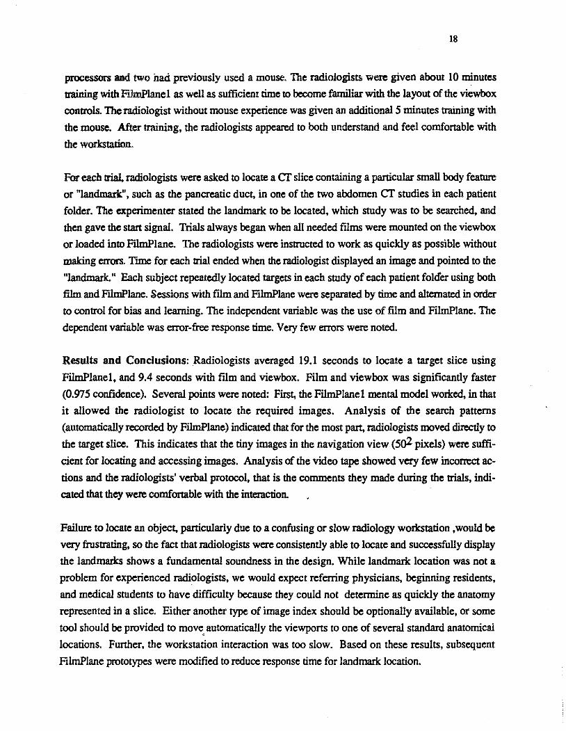
processors and two had previously used a mouse. The radiologists were given about 10 minutes
training with F!.lmP!anel as well as sufficient time to become familiar with the layout of the viewbox
controls. The radiologist without mouse experience was given an additional 5 minutes training with
the mouse. After training, the radiologists appeared to both understand and feel comfortable with
the workstation.
For each trial. radiologists were asked to locate a cr slice containing a particular small body feature
or "landmark", such as the pancreatic duct, in one of the two abdomen cr studies in each patient
folder. The experimenter stated the landmark to be located, which study was to be searched, and
then gave the start signal. Trials always began when all needed films were mounted on the viewbox
or loaded into FilmPlane. The radiologists were instructed to work as quickly as possible without
making errors. Time for each trial ended when the radiologist displayed an image and pointed to the
"landmark." Each subject repeatedly located targets in each study of each patient fold"er using both
film and FllmP!ane. Sessions with film and FilmPlane were separated by time and alternated in order
to control for bias and learning. The independent variable was the use of film and FilmPlane. The
dependent variable was error-free response time. Very few errors were noted.
Results and Conclusions: Radiologists averaged 19.1 seconds to locate a target slice using
FilmPlanel, and 9.4 seconds with film and viewbox. Film and viewbox was significantly faster
(0.975 confidence). Several points were noted: First, the FilmPlanel mental model worked, in that
it allowed the radiologist to locate the required images. Analysis of the search patterns
(automatically recorded by FilmPlane) indicated that for the most part, radiologists moved directly to
the target slice. This indicates that the tiny images in the navigation view (5o2 pixels) were suffi
cient for locating and accessing images. Analysis of the video tape showed very few incorrect ac
tions and the radiologists' verbal protocol, that is the comments they made during the trials, indi
cated that they were comfortable with the interaction.
Failure to locate an object, particularly due to a confusing or slow radiology workstation , would be
very frustrating, so the fact that radiologists were consistently able to locate and successfully display
the landmarks shows a fundamental soundness in the design. While landmark location was not a
problem for experienced radiologists, we would expect referring physicians, beginning residents,
and medical students to have difficulty because they could not determine as quickly the anatomy
represented in a slice. Either another type of image index should be optionally available, or some
tool should be provided to move. automatically the viewports to one of several standard anatomical
locations. Further, the workstation interaction was too slow. Based on these results, subsequent
FilmP!ane prototypes were modified to reduce response time for landmark location.

19
Locating slia:!! containing landmarks appears to be a good task for evaluating the radiologist's gen
eral comprebrmsion of the workstation mental model and navigation. While the only formal depen
dent variable is response-time, the other observations mentioned above must be taken into consider
ation before one can assume that workstation design is viable.
5.2 Experiment Two
The second experiment detennined the time to interpret four patient folders each containing a current
and a previous abdomen cr study using film and FilmPiane. No prior interpretation report, patient
history, or requisition form were provided.
Material and Methods: FilmPianel, the viewbox, the subjects, and the experimentai environment
were the same as in experiment one. For each trial, The radiologists were asked to look through
both abdomen cr studies and "indicate anything they could about the patient." This task utilizes
image access-patterns similar to a standard diagnostic task without prior knowledge. Radiologists
were instructed to "insure their interpretation quality was up to typical professional standards."
Tasks were timed from the moment the films were loaded onto the viewbox, or displayed on the
navigation view, until the end of the interpretation. The time to load and unload the films on the
viewbox was also measured. In addition to verbal protocol, observation data were gathered manu
ally, by computer, and with video tape. Radiologists were asked to describe how confident they
were in their interpretations. During two separate sessions, each radiologist read two studies using
FilmPlane, and two studies using film and viewbox. Presentation method and patient folder orders
were systematically varied to control for learning and bias.
Results and Conclusions: FilmPianel averaged 482 seconds for interpretation of these ab
domen studies. An interpretation with ftlm and viewbox averaged 264 seconds. Film and viewbox
were significantly faster (0.995 confidence). In general, the following pattern was used to review
the two cr studies: first, the radiologist sequentially scanned all the images in the older study, and
second, a differential comparison of the old and the new study was made by splitting the screen into
two viewpons, moving the halves to the top of each study, and then moving the half viewpons
down through both studies, side-by-side comparing the corresponding images. During this compar
ison, only two slices from each study could be simultaneously viewed. This is insufficient, and ei
ther more display area is required, or the images would have to be viewed at lower resolution. We
suspect that had the requisition form and/or the interpretation report for the previous study been pre-

20
sent, the initiai .equential scan through the older smdy would have been replaced with a highly-di
rected viewing of the anatomical area in question.
'The radiologists felt they were able to conduct viable inte:pretations with the FilmPlanel worlcstation
for patient foiders containing two abdomen CT studies. However, they also felt the system had
"imposed itself' on them during the interaction, that is, they had found themselves thinking about
manipulating the workstation rather than thinking about interpreting the images. The radiologists
had only the training and experience from experiment one so a cenain unfamiliarity is expected.
Nevertheless. this initial version of FilmPlane had too much "friction" in the interaction. To correct
this, the system has been refined using the time-motion calculations described in the next section.
In addition, the single 10242 available for the experiment did not appear to have sufficient display
area for comparing two CT studies at full resolution. On the average, each radiologist made 3.3
arbitrary-access moves and 69 sequential moves when viewing each patient folder intlicating both
that the radiologists understood the FilmPlane 1 mental model, and the importance of reducing the
time for a single sequential movement operation.
Ideally, one should not measure response time without carefully measuring accuracy. However,
precisely measuring interpretation quality with receiver operating characteristics (ROC) [ 48] or
agreement experiments [49] requires from 200 to 300 data points [33,48], many hundreds of hours
of scarce radiologist time, and many months of experimenter time. While ROC or agreement exper
iments are required to analyze the effectiveness of a worlcstation compared to another display device,
they are too time consuming to be part of the worl<:station development cycle. Thus experiment two
is an appropriate experiment design for providing rapid feedback on navigation to interface design
ers, and as a formal framework for observing radiologists use a workstation.
5.3 Time-Motion Analysis
Once a general workstation design has been accepted, the design must be "lapped" and improved to
reduce "friction". Besides observation and user comments, one of the best methods for rapidly pol
ishing an interaction is with the use of time-motion analysis calculations. In brief, time motion anal
ysis is used to estimate how long a user will require to perform a specific task using a specific tool
[50]. Time motion analysis of a small aspect of a computer tool can be as simple as counting
keystrokes or as complex as a detailed keystroke analysis [51] which takes into account the mental
pauses .a user makes, even when doing a complex but well-learned task.

21
After completing the above experiments, we used the keystroke modei to compare several alternative
interactions for sequential movement in FilmPlane2 [ 45]. While the keystroke modei was designed
for analysis of experts and our users are novices, it is still valid for comparing two design alterna
tives. To verify the accuracy of the time-motion analysis model, we used it to calculate the duration
of a sequential movement operation with FilmPlanel, and then conducted several simple timing
studies of this operation. Generally, the keystroke estimates were within 0.1 second of the actual
sequential-mo\'-ement duration. These keystroke estimates showed that the old sequential operation
took 2.7 seconds while the improved sequential operation would take about 1.6 seconds. Additional
analysis show that only 47 sequential operations would be needed with the new interface to complete
the same task requiring 69 operations with the old. These changes would result in a total potential
improvement of about 110 seconds out of the 482 average for the task in experiment two. Together
with several other improvements, this new sequential access method should cut interpretation time . almost in third for patient folders containing two cr abdomen studies and no previous information.
Considering the weeks of time required to conduct even a simple experiment, time-motion analysis,
even with its limited accuracy, is an important tool in CHI development. Further, the analysis
comes before the prototype has been implemented, further reducing the time for obtaining feedback
on a design idea.
6. CONCLUSIONS
In this paper, we have described the issues and problems with radiology-workstation navigation de
sign and described the objectives and design of the FilmPlane2 radiology workstation as well as our
human computer interaction strategy. We have also presented three rapid evaluation techniques for
quickly gaining feedback on a radiology workstation navigation design. Radiology workstations are
the essential component to the acceptance of electronic medical image management, and adequate
workstation computer-human interaction is essential to workstation acceptance.
In general, radiologists are currently not willing to work without film using a computer workstation,
even if all modalities are available on-line. This is understandable for the information bandwidth of
even the best workstations, including FilmPlane, is still insufficient. This seems particularly true
for interpretations involving multiple studies. Analogously, as scientists, engineers, and toolsmiths,
we are still unwilling to work without paper using our computer workstations. Radiologists have
become understandably skeptical of success claims after repeatedly hearing of new workstations and
constantly"finding them unacceptable.

22
Nevenheless. there is a light at the end of the PACS tunnel. Relatively low cost 20482 display
monitors of acceptable quality are available, as are worlcstation busses that can move 60 million 32
bit pixels a second. All this, in our opinion, adds up to sufficient hardware to construct viable radi
ology workstations. Now can begin the process of developing, evaluating. evolving, and lapping
the surfaces of a viable tool.
7. ACKNOWLEDGMENTS
We gratefully acknowledge our colleagues Steve Pizer, R Eugene Johnston, Diane C. Rogers, Vic
tor Klymenko, Jonathan Walker, Osamu Toki, Robert Cromartie, Davd Washburn, and Jim Syman
both for work on which this paper is based and for useful conversations. Our radiologist colleagues,
J. Randolph Peny, Jeffrey Creasy, Claire Wilcox, Paul Jaques, Ira Bell, and Marcia Kooman have '
provided a critical contribution of the clinical issues of display. We thank Terri Bass and Joy Justus
for help with the manuscript. This work was supported by NIH grants (ROl CA 44060, POl CA
47982).
8. REFERENCES
[1] M.M Mantei and T.J. Teorey, "Cost/Benefit Analysis for Incorporating Human Factors in the
Software Life Cycle,"CACM, (31)4: 428-439, Aprill988.
[2] F.P. Brooks, "The. Computer 'Scientist' as ToolSmith: Studies in Interactive Computer
Graphics," Information Processing 77, b. B. Gilchrist, Ed., Nonh-Holland, pp. 625-634.,
1977.
[3] S.M. Pizer, R.E.Johnston, D.C Rogers, and D.V. Beard, "Effective Presentation of Medical
Images on an Electronic Display Station," RadioGraphies, 7(6):1267-1274, 1987.
[4] S.M. Pizer and D.V. Beard,"Medical Image Workstation: State of Science & Technology,"
Submitted to The Journal of Digital Imaging.
[5] D.V. Beard, R.E. Johnston, 0. Toki, and C. Wilcox, "Search Patterns for Viewing Multiple
Cf Chest Images: an Eyetracking Study," submittedto Investigative Radiology.

23
[6] D.C Rog·llrt;, R.E. Johnston, B.M. Hemminger, and S.M. Pizer. "Development of and
Experience With a Prototype Medical Image Display," Abs. of Farwest Image Perception
Confer=:e, Univ. of New Mexico, Dept. of Radiology, 1986.
[7] D.V Beard. S.M. Pizer, D.C. Rogers, and R. Cromartie, "A Prototype Single-Screen PACs
Console Development Using Human Computer Interaction Techniques," SPIE Medical
Imaging 767: 646-653,1987.
[8] H.L. Ktmdel and D.J. Wright, ''The Influence of Prior Knowledge on Visual Search Strategies
During the Viewing of Chest Radiographs," Radiology 93: 315-320, 1969.
[9] A.S. Gale and B.S. Worthington, "The Utility of Scanning Strategies in Radiology," Eye '
Movements and Psychological Functions: International Views ,Groner, R, Menz, C, Fisher,
DF, and Monty, RA, eds., Hillsdale, NJ: Erlbaum, 1983.
[10] D.P. Carmody, C.F. Nodine, and H.L. Kundel, "Global and Segmented Search for Lung
Nodules of Different Edge Gradients," Investigative Radiology 15: 224-233, 1980.
[11] H.L Ktmdel and P.S. LaFollette, "Visual Search Patterns and Experience with Radiological
Images," Radiology 103: 523-528, 1972.
[12] J. Yerushalmy,"The Statistical Assessment of the Variability in Observer Perception and
Description of Roentgenographic Pulmonary Shadows," Radiology Clinics of North America
1: 381-392, 1969.
[13] M.J. Smith, Error and Variation in Diagnostic Radiology, Springfield, IL: CC Thomas,
148,1967.
[14] W.J Tuddenham, "Visual Search, Image Organization, and Reader Error in Roentgen
Diagnosis: Studies of the Psychophysiology of Roentgen Image Perception," Radiology , 78:
694-704,1962.
[15] E. Llewellyn-Thomas, "Search Behavior," Radiology Clinics of North America 1: 403-
417,1969.

24
[16] W.J Tuddenham and W.P Calvert, "Visual Search Patterns in Roentgen Diagnosis," Radiology
76: 225-256,1961.
[17] H.L Kundel, C.F Nodine, and D. Carmody, "Visual Scanning, Pattern Recognition and
Decision-Making in Pulmonary Nodule Detection," Investigative Radiology 13,1978.
[18] E. Rogers and M. Goldberg,"Image organization and investigation strategies for a radiological
workstation," SP/E Medica/Imaging Ill, Voll091, Newport Beach, CA January 1989.
[19] N. Carboni, J. Tombaugh, and R. Dillon, "The effect of simultaneous vs sequential viewing of
digital images on comparative judgement performance," SP IE M edicali maging III. Vol. I 091 ,
Newport Beach, CA, January, 1989.
[20] H. Fuchs, M. Levoy, and S. M. Pizer, "Interactive Visualization of 3D Medical Data," IEEE
Computer, August, 1989.
[21] M. Levoy, "Display of Surfaces from Volume Data," IEEE Computer Graphics and
Applications, Vol. 8, No.3, May, pp. 29-37, 1988.
[22] S.M. Pizer, "Psychovisual Issues in the Display of Medical Images," Pictorial Information
Systems in Medicine, K. H. Hoehne, ed., 235-250, Springer-Verlag, Berlin, 1985.
[23] H. MacMahon, C. Vyborny, C. Metz, K. Doi, V. Sabeti, and S. Solomon, "Digital
Radiography of Subtle Pulmonary Abnormalities: An ROC Study of the Effect of Pixel Size on
Observer Performance," Radiology, 158, pp.21-26, 1986.
[24] D.P Chakraborty, E.S. Breatnach, et al., "Digital and Conventional Chest Imaging: A Modified
ROC Study of Observer Performance Using Simulated Noduals," Radiology, Jan. vol. 158,
pp. 35-39' 1986.
[25] L.R Goodman, W.D. Foley, et a!., Digital And Conventional Chest Images: Observer
Performance with Film Digital Radiography System," Radiology, Jan. !58 27-38, 1986.
[26] P.F. Judy, R.G. Swensson, D. Twible, and L. Menelly,"Effects of Display Level on
Detectability of Small Lesions on CT Images," Medical Physics 10 (4): 525, 1982.

25
. [271 P.F Judy and R.G Swensson, ··Detection of Small Focal Lesions in CT Images: Effects of
Reconstruction Filters and Visual Display Windows", Brit. J. Radiology 58: 137-145, 1985.
[28] G. Seeley, E. Robles-Sotel:>, G. Cannon, J. Bjelland, T. Ovitt. J. Standen, M. Capp, H.
Fisher, and W. Dailas, "The Use of Psychophysics As A System Design Aid: Comparison of
film-screen to an electronic review console," Medical Imaging , SPIE, 767, pp. 639-643,
1987.
[29] ACR Engineering Research in Visual Perception. A publication by the American Association of
Radiology,l986.
[30] S. Horii, H. Horii, and P. Kowalski, "Eclectic Look at Viewing Station Design," Medical
Imaging II, SPIE, 914, 1988.
[31] S.M. Pizer, E.P. Amburn, J.D. Austin, R. Cromartie, A. Geselowitz, T. Greer, B.M. ter Haar
Romeny, J.B. Zimmerman, and K. Zuiderveld, "Adaptive Histogram Equalization and Its
Variations," Computer Vision, Graphics, and Image Processing, 4(3), pp. 355-368, 1987.
[32] J.B. Zimmerman, "Effectiveness of Adaptive Contrast Enhancement," Ph.D. Dissertation,
Department of Computer Science, University of North Carolina, 1985.
[33] J.B. Zimmerman, S.M. Pizer, E. Staab, J. Perry, W. McCartney, and B. Brentou, "An
Evaluation of the Effectiveness of Adaptive Histogram Equalization for Contrast
Enhancement," IEEE Transactions on Medical Imaging, 7(4): 304-312, 1988.
[34] D. Rumelhart and D. Norman, "Analogical processes in learning," In Cognitive Skills and their
Acquisition, edited by Anderson, J.R. (Hillsdale, NJ:Erlbaum), pp. 335-359, 1981.
[35] R. Young, "The machine inside the machines: User's models of pocket calculators,"
I nternationa/J ournal of Man-Machine Studies vol 15. pp51-85, 1981.
[36] D. Foss, M. Rosson, and P. Smith, "Reducing manual labor: An experimental analysis of
learning aids for a text editor," Proceedings of the Gaithersburg Conference on Human Factors
in Computing Systems (Washington, DC: National Bureau of Standards), pp 332-336,1982.

26
[371 F. Halasz and T .P. Moran, "Analogy considered harmful,'' Proceedings of the Gaithersburg
Conference on Human Factors in Computing Systems (Washington, DC: National Bureau of
Standards), 1982.
[381 S.K. Douglas and T.P. Moran, "Learning text editor semantics by analogy," Proceedings of
the CH/'83 Conference on Human Factors in Computing Systems, 1983.
[39] S.T. Dumas and W.P. Jones, "A comparison of symbolic and spatial filing," Proceedings of
the CHI '85 Conference on Human Factors in Computing Systems, ACM, 1985.
[40] J.R. Olson, J.M. Carrol, and N. Anderson, "What does the User of Software Know? Mental
Model and Software Human Factors," Proceedings of the Workshop on Software Human •
Factors: Users Mental Models, (Available from: Committee on Human Factors, National
Research Console, 2101 Constitution Avenue, NW, Washington, DC 20418), 1987.
[41] D.V. Beard, R. Cromartie, J. Creasy, and J. Symon, "Experiment Comparing Image-Locating
on Film and the FILM-PLANE Radiology Workstation." SPIE Medica/Imaging ll,, 914,
1988.
[42] B. Schneiderman, "Direct Manipulation: A Step Beyond Programming," IEEE Computer, Vol.
16, pp 57-69, 1983.
[43] Macintosh System Software User's Guide, Apple Computer, Inc., 20525 Mariani Avenue, Cu
pertino, Ca 95014, 1988.
[44] K. McNeill and H. Fisher, "A Model for Radiologic Workstation User Interface Design,"
Medical Imaging, SPIE, 767:713-716, 1987.
[45] D. V. Beard, J.G.F. Walker, I. Bell, and R. Cromartie, "Evolved Design of a Radiology
Workstation Using Time-Motion Analysis and the Keystroke Model" SPIE Medical Imaging
Ill vol. 1091, 1989.
[46] B. Schniedennan, Designing The User Interface , Addison-Wesley, Reading, MA., 1987.
[47] A. Goldberg, and D. Robson, Smalltalk-80: The Language and its Implementation. Addison
Wesley, Reading, MA., 1983.

27
1481 C.E. Metz and H. B. Kronman. ''Statistical Significance Tests for Binormal ROC Curves,"
Journal of Mathematical Psychology, 22,3, 218-243, 1983.
[4!/j R.E. Johnston, J. Perry, S. M. Pizer, D.C. Rogers, and B. Yankaskas, B "Agreement
Experiments: A Method for Quantitatively Testing New Medical Image Display Approaches,"
Medical Imaging II, SPJE, 1988.
[50] S.K. Card, T.P. Moran, and A. Newell, The Psychology of Human-Computer Interaction ,
Lawrence Erlbaurn Associates, Hillsdale, New Jersey, 1983.
[51] S.K. Card, T.P. Moran, A. Newell, "The Keystroke-Level Model for user performance time . with interactive systems, "CACM, vol. 23, pp. 296-410, 1980.


