
DGS - Danfoss Gas Sensor SC / IR model Installation & Operation
Installation and Operation Guide
ADAP-KOOL® Refrigeration Control System
2 Installation & Operation USCO.EI.S00.A2.02 © Danfoss 06-2014 DGS
Contents1 - Installation Instructions ........................................................................ 22 - Location Instructions ............................................................................. 33 - Typical Setting .......................................................................................... 44 - Installation and Wiring Diagrams ...................................................... 45 - Operating Instructions .......................................................................... 46 - Test / Function Instructions ................................................................. 47 - Remote sensor head installation ....................................................... 68 - DGS - Annual Test .................................................................................... 69 - Agree Selectable functions with end-users ................................... 610 - Troubleshooting .................................................................................... 611 - Connections to Danfoss Control Panels ....................................... 612 - Mounting Diagrams ............................................................................. 7
*Technician use onlyThis unit must be installed by a suitably qualified technician who will install this unit in accordance with these instructions and the standards set down in their particular industry/coun-try. Suitably qualified operators of the unit should be aware of the regulations and standards set down by their industry/country for the operation of this unit. These notes are only intended as a guide and the manufacturer bears no responsi-bility for the installation or operation of this unit.Failure to install and operate the unit in accordance with these instructions and with industry guidelines may cause serious injury including death and the manufacturer will not be held responsible in this regard.
1 - DGS Installation InstructionsTo open the Standard Sensor enclosure: turn the cable gland ½ turn anticlockwise to loosen the internal gland nut, depress the clip on top of the enclosure and open. Reverse to close.
Power: 12-24V AC / DC, connect at positions 0V and +V at connector block CN1. For AC – Jumper A is on, D is off. (See Diagram 1/2)For DC – Jumper A is off, D is on. (Default Factory Setting is DC)Use 2 cores of a 4-core cable, low voltage alarm type, typically 7/0.2 mm sq
Output: you can select the V or mA analogue output at JP1 and JP3. (Default factory setting is mA) Connect the other two cores of the cable to terminal block CN2 positions 0V and V or I for volt-age or current as per jumper selection. You can common the two zeros and use 3 core cable if preferred.
connect 4-20mA at CN 2 positions 0V and Iconnect voltage output at CN 2 positions 0V and V
Relay set point: P1 sets the trip point for the relay and sounder using the 0 -5V scale (measure at test points 0V and REF1, 2.5V would be equivalent to half the range - (500ppm on a scale of 0-1000ppm) Default factory setting is 50% of the range.
Time delay: A time delay for the operation of the relay and sounder can be selected using jumpers JP5 and JP6. Default fac-tory setting is zero.
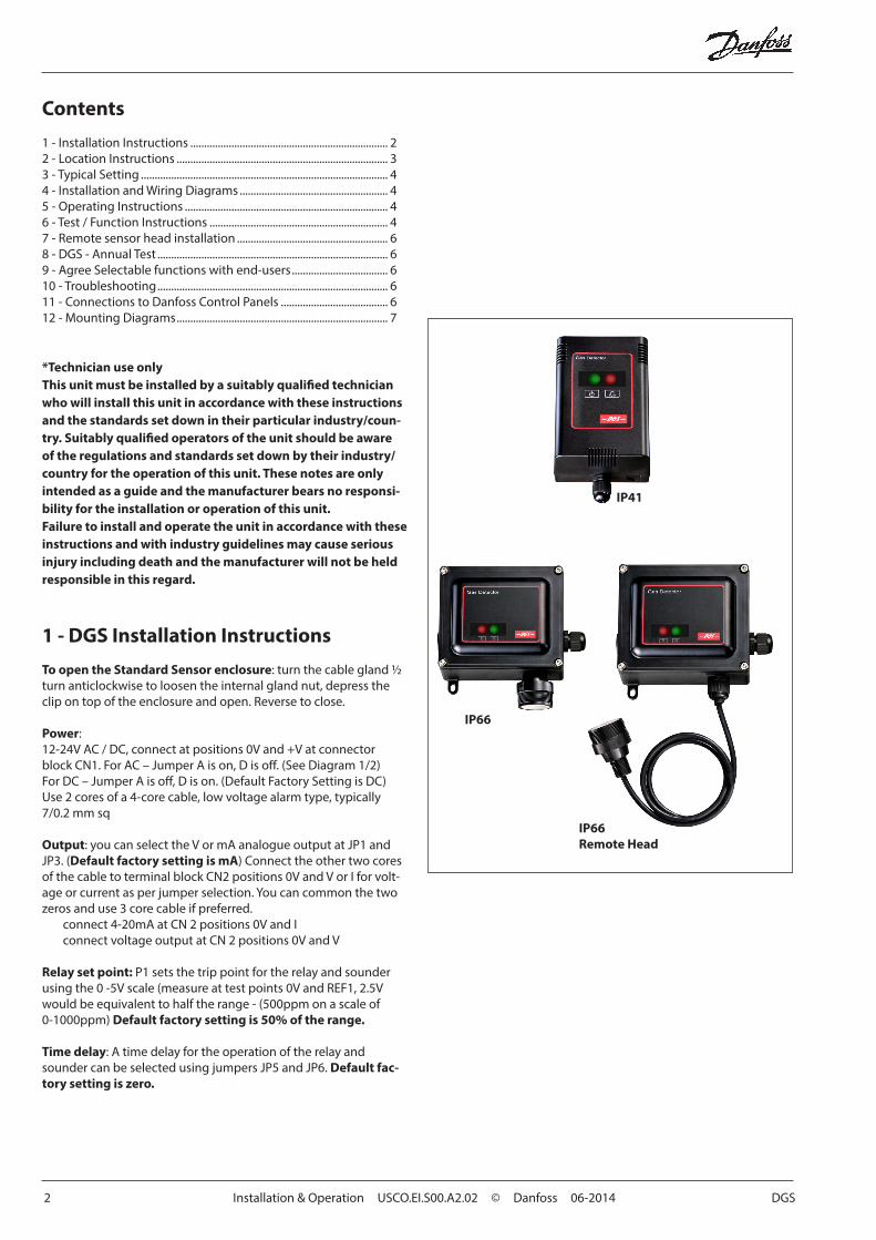
IP41
IP66
IP66Remote Head
DGS Installation & operation USCO.EI.S00.A2.02 © Danfoss 06-2014 3
Sounder: The sounder can be disabled using jumper JP2. Default factory setting is enabled.
There is a 5-minute power up delay to allow the sensor to stabilize. This can be cancelled by momentarily shorting between either of the upper and lower pads of SW1 or SW2.
2 - DGS - Location instructionsLocation of SensorsSensors must be located within the appropriate wire lengths from the central control unit (if used).In all cases the sensor supplied is designed for maximum sensitiv-ity to a particular gas.
However, in certain circumstances false alarms may be caused by the occasional presence of sufficiently high concentrations of other gaseous impurities. If such a situation is likely to arise install-ers should check with our Technical Department so that sensor (s) of suitable cross sensitivity can be supplied. Examples of situations where such abnormalities may arise include.
• Plant room maintenance activity involving solvent or paint fumes or refrigerant leaks.
• Plant rooms in fruit ripening/storage facilities because of ac-cidental gas migration (bananas - ethylene, apples - carbon dioxide)
• Heavy localised exhaust fumes (carbon monoxide, dioxide, pro-pane) from engine driven forklifts in confined spaces or close to sensors.
A response delay may be selected to minimise any problems that might arise.
Machinery roomsThere is NO ABSOLUTE RULE in determining the number of sen-sors and their location. However a number of simple guidelines will help to make a decision. Sensors monitor a point as opposed to an area. If the gas leak does not reach the sensor then no alarm will be raised. Therefore, it is extremely important to carefully select the sensor location. Also consider ease of access for main-tenance.
The size and nature of the site will help to decide which method is the most appropriate to use. Locations requiring the most protec-tion in a machinery or plant room would be around compressors, pressurised storage vessels, refrigerant cylinders or storage rooms or pipelines. Most vulnerable are valves, gauges, flanges, joints (brazed or mechanical), filling or draining connections etc
When mechanical or natural ventilation is present mount a sensor in the airflow. In machinery rooms where there is no discernable or strong airflow then options are:
• Point Detection, where sensors are located as near as possible to the most likely sources of leakage, such as the compressor, expansion valves, mechanical joints or cable duct trenches, and,
• Perimeter Detection, where sensors completely surround the area or equipment.
• With heavier than air gases such as halocarbon and hydrocarbon refrigerants such as R404A, propane, and butane sensors should be located near ground level
• With lighter than air gas e.g. ammonia, the sensor needs to be located above the equipment to be monitored on a bracket or high on a wall within 300 mm of, or on the ceiling provided there is no possibility of a thermal layer trapped under the ceiling preventing gas reaching the sensor. (NB. At very low tempera-tures, such as in a refrigerated cold store, ammonia gas becomes heavier than air).
• With similar density or miscible gases, such as CO or CO2, sensors should be mounted about head high – say 1.5m.
• Sensors should be positioned a little way back from any high-pressure parts to allow gas clouds to form. Otherwise any leakage of gas is likely to pass by in a high-speed jet and not be detected by the sensor.
• Make sure that pits, stairwells and trenches are monitored since they may fill with stagnant pockets of gas.
• If a pressure relief vent pipe is fitted to the system, it may be a re-quirement to mount a sensor to monitor this vent pipe. It should be positioned about 2 m above the PRV to allow gas clouds to form.
• With racks or chillers pre-fitted with refrigerant sensors, these should be mounted so as to monitor the compressors or if ex-tract ducts are fitted the airflow in the duct may be monitored.
Refrigerated SpacesIn refrigerated spaces sensors should be located in the return air-flow to the evaporators on a sidewall, below head high preferred, or on the ceiling, not directly in front of an evaporator. In large rooms with multiple evaporators, sensors should be mounted on the central line between 2 adjacent evaporators, as turbulence will result in airflows mixing.
ChillersIn the case of small water or air-cooled enclosed chiller units mount the sensor so as to monitor airflow to the extract fans. With larger models also place a sensor inside the enclosure under or adjacent to the compressors
In the case of outdoor units:
• such as enclosed air-cooled chillers or the outdoor unit for VRV/VRF systems mount the sensor so as to monitor airflow to the ex-tract fan. With large units also place a sensor inside the enclosure under or adjacent to the compressors
In the case of non-enclosed outdoor units
• If there is an enclosed machinery section then locate a sensor there.
• In the case of units with enclosed compressors, mount sensors in the enclosures
• Where you have protective or acoustic panels mount the sensor low down under the compressors where it is protected by the panels.
• With air-cooled chillers or air-cooled condensers with non-enclosed condenser sections it is difficult to effectively monitor leaks in the coil sections. With some designs it will be possible using an airflow sensor to monitor airflow to the start –up fans in the front or rear sections.
• If there is a possibility of refrigerant leaks into a duct or air-han-dling unit install a sensor to monitor the airflow.
Weatherproof sensors should be used for unprotected outdoor applications.

4 Installation & Operation USCO.EI.S00.A2.02 © Danfoss 06-2014 DGS
3 - DGS -Typical SettingsGas: Refrigerant R404A Range: 0-1000ppm Alarm Set Point: 500ppm
For a particular unit please refer to the gas settings shown on the rating plate.
4 - DGS -Installation and wiring diagram
See diagrams 1 and 2.
In a hotel room monitoring in ceiling voids would not strictly comply with EN378
Air Conditioning – Direct systems VRF/VRVEN378 states that at least one detector shall be installed in each occupied space being considered and the location of detectors shall be chosen in relation to the refrigerant and they shall be located where the refrigerant from the leak will collect. In this case refrigerants are heavier than air and detectors should have their sensors mounted low .e.g. at less than bed height in the case of an hotel or other similar Category Class A spaces. Ceiling or other voids if not sealed are part of the occupied space.
CAUTION
Don’ts
• Do not mount sensors– under mirrors– at vanity units– in or near bathrooms
Do’s • mount the in-room sensor
at less than the normal heights of the occupants e.g in a hotel room this is less than bed height - between 200-500mm off the floor.
• away from draughts and heat sources like radiators etc.
• avoid sources of steam
5 - DGS -Operating instructions1- On powering up it will sense for the presence of gas after an
initial warmup delay of 5 minutes, the green LED will flash at 1 second intervals during the warm-up.
2- In alarm condition:• the green LED stays on• the red LED will be on• the siren operates (if it has not been disabled and after a delay
if this option has been selected)• the relay output activates (after a delay if this option has been
selected)• the voltage or current output changes proportional to gas
concentration
3- Fault condition:• the green LED will be off• the red LED will be on• a voltage or current fault output will activate
2mA on the 4-20mA output0.5V on the 1-5V output1.0V on the 2-10V output
6 - DGS - Test / Function InstructionsThe DGS is calibrated in the factory and does not require to be calibrated on installation. After installation the units should be bump tested. Expose the sensors to test gas using a Danfoss ampoule (CO2) or test cylinder (appropriate to the installation) or crack open the valve of a cigarette lighter (only for Semiconduc-tor units) without igniting it and hold it over the vent holes on the upper right side of the DGS. The gas is heavier than air and should fall into the DGS. This will put the system into alarm. The red LED will light showing the system is in alarm. The delay will prevent the siren sounding or relay switching for the preset delay, if delay is set.
With a bump test you can see the functions of the sensor - the red led will light, the relay and sounder will function, the output selected, say 0-10V- will show the gas level.
To test the siren and or relay function, check the delay is set at zero using the header as shown on the installation diagram and expose to gas as above. You can mute the siren by removing the jumper JP2.
After the gas has cleared the red led, siren and relay will automati-cally reset.
Before testing the sensors on site the DGS must have been pow-ered up and allowed to stabilize.
DGS Installation & operation USCO.EI.S00.A2.02 © Danfoss 06-2014 5
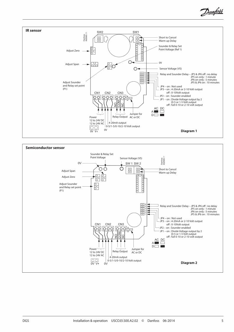
Diagram 1
IR sensor
Adjust Zero
Adjust Span
Adjust Sounderand Relay set point(P1)
Short to CancelWarm up Delay
Sounder & Relay SetPoint Voltage (Ref 1)
0V
Sensor Voltage (VS)
Relay and Sounder Delay – JP5 & JP6 off : no delay JP5 on only : 1 minute JP6 on only : 5 minutes JP5 & JP6 on : 10 minutesJP4 – on : Not usedJP3 – on : 4-20mA or 2-10 Volt output off : 0-10Volt outputJP2 – on : Sounder enabledJP1 – on : Divide Voltage output by 2 (0-5 or 1-5 Volt output off : full 0-10 or 2-10 volt output
Power12 to 24V DC12 to 24V AC
0V0-5/1-5/0-10/2-10 Volt output
4-20mA output
Relay OutputJumper forAC or DC
0V V+
Diagram 2
Semiconductor sensor
Adjust Span
Adjust Zero
Adjust Sounderand Relay set point(P1)
Short to CancelWarm up Delay
Sounder & Relay SetPoint Voltage Sensor Voltage (VS)
Relay and Sounder Delay – JP5 & JP6 off : no delay JP5 on only : 1 minute JP6 on only : 5 minutes JP5 & JP6 on : 10 minutesJP4 – on : Not usedJP3 – on : 4-20mA or 2-10 Volt output off : 0-10Volt outputJP2 – on : Sounder enabledJP1 – on : Divide Voltage output by 2 (0-5 or 1-5 Volt output off : full 0-10 or 2-10 volt output
Power12 to 24V DC12 to 24V AC
0-5/1-5/0-10/2-10 Volt output4-20mA output
Relay OutputJumper forAC or DC

6 Installation & Operation USCO.EI.S00.A2.02 © Danfoss 06-2014 DGS
7 - DGS - Sensor - Remote sensor head installationIf you do not wish to surface mount the DGS or need to match room decor, we can supply a remote sensor with a decorative faceplate (standard: brushed stainless steel). The remote sensor is mounted in an electrical back box 44mm deep to which the vented face plate is fitted.
1. Remove the connector from the sensor PCB to feed the cable through the trunking.
2. Immediately refit the connector to the sensor board in the back-box. The DGS and remote sensor must be kept together as they are calibrated together and are a matched pair.
3. If construction / decoration is still going on, fit a standard plastic blanking plate immediately you install the sensor in the back box to avoid dust or damage to the in-room sensor. You can fit the SS vented plate when decoration is completed.
4. Cleaning: the decorative face plate should be lightly dusted – it should not be sprayed with cleaning/polishing aerosols.
8 - DGS Sensor - Annual TestTo comply with the requirements of EN378 and the F GAS regula-tion sensors must be tested annually. However local regulations may specify the nature and frequency of this test. If not the Dan-foss recommended procedure should be followed. Contact us for details.
After exposure to a substantial gas leak, sensor should be checked and replaced if necessary.
CAUTION
Do not remove the sensor boards from a number of units at the same time in case they get mixed up. If doing so, label them, or, ensure you check the serial number on the main PCB and the remote sensor PCB are the same when reinstalling.
Check local regulations on calibration or testing requirements.
CAUTION
9 - Agree Selectable functions with end-users:You should agree these important functions with the customer so that the system will operate as he/she requires:
1. Time Delay Response: available on the sounder and relay to avoid false alarms. This is set with jumpers. The default delay is 0 minutes. You may wish to set to 15 minutes during start up and construction if you may have VOC (volatile organic compounds) fumes, paint etc in the rooms. They should be reset as required.
2. Siren: The units have an internal siren. You can disable this by jumper but the default setting is “enabled” in compliance with EN378. The customer may not want local alarms especially if you are connecting to a remote monitoring system. Check the customer’s preference.
3. Output: Agree the output required 4-20mA, or 0-10V etc
4. Connectivity: Decide how the outputs are to be used. Danfoss gas detectors can activate external systems such as fans or shut down and activate sirens, warning lights, activate dial out sys-tems, or connect to most BMS, SCADA, or other control systems using one or more outputs.4-20mA, 0-10V, 0-5V, 2-10V or 1-5V.Relay 1Amp at 24VDC or 120V AC.
10 - DGS - Troubleshooting
All DGS units are checked and calibrated before shipment.
1. Symptom: Green /Red light on sensor is not lit.Possible Cause: Power supply. Possible wiring fault . Check power supply, check your wiring DGS possibly damaged in tran-sit. Check by installing another DGS to confirm fault.
2. Symptom: red light on, green led off, indicates a fault
2.1 Sensor element may be disconnected from printed circuit board. check to see sensor element is properly inserted into board.
2.2 If it is then possibly the sensor element has been damaged or has reached end of life and needs to be exchanged. Contact us for instructions and support.
3. If you experience spurious alarms in the absence of a leak, con-tact us for instructions and support.
During operation record any alarms. Establish the cause or likely cause if no leak has occurred. Report these occurrences to your supplier or Danfoss, and we will advise on corrective measures.
11 – Danfoss Control panelsFor connection instructions, refer to the relevant Danfoss controller manual.

DGS Installation & operation USCO.EI.S00.A2.02 © Danfoss 06-2014 7
12 – Mounting Instructions
DGS Standard Sensor
50 mm
75 mm
IP66 (with Splashguard)
Splashguard
IP66 Remote Head, M42 thread, 3m CableOption- special request, contact Danfoss
Exd Remote Head,thread varies with model,5 m Cable
thread varies with model
PRV/IP66 Vent PipeMonitoring 1’’ BSP Head 3 m Cable
1”BSP thread
mounting slots =9mm long x 6mm wide use 5mm - 6mm screws
mountingmeasurements
Mounting locations as in IP66
M42 thread
8 Installation & Operation USCO.EI.S00.A2.02 © Danfoss 06-2014 DGS
AD
AP-
KOO
L®
Danfoss can accept no responsibility for possible errors in catalogues, brochures and other printed material. Danfoss reserves the right to alter its products without notice. This also applies to productsalready on order provided that such alternations can be made without subsequential changes being necessary in specifications already agreed.All trademarks in this material are property of the respecitve companies. Danfoss and Danfoss logotype are trademarks of Danfoss A/S. All rights reserved.


