
DIAGNOSTYKA - DIAGNOSTICS AND STRUCTURAL HEALTH MONITORING 3(59)/2011 GRZ DZIELA, Diagnostics gas turbine rotors in non stationary states
41
DIAGNOSTICS GAS TURBINE ROTORS IN NON STATIONARY STATES
Andrzej GRZ DZIELA
Wydzia mechaniczno – Elektryczny, Akademia Marynarki Wojennej Ul. midowicza 69, 81-103 Gdynia, Fax. 058 626 26 48, e-mail: [email protected]
Summary
Vibration tests of marine gas turbine engines are performed as research of on-line and off-line types. On-line Systems generally monitored one or two vibration symptoms, which asses the limited and/or the critical values of parameters and they, potentially, can warn and/or shutdown engines. Off-line Systems are usually used for vibration analysis during non-steady state of work. The paper presents comparison of different methods of analysis of vibration symptoms measured under run-up and shut-down processes of marine gas turbine engines. Results of tests were recorded on gas turbine engine DR76 type of the COGAG type propulsion system. Main goal of the research was qualified on helpfulness and unambiguous result, from synchronous measurement, order tracking and auto tracking. All vibration symptoms were chosen from the methodology of the diagnosing gas turbine engines operated in the Polish Navy, called Base Diagnosing System. Second purpose of the paper was the estimation of the possibility of usage those analysis methods of gas turbine engines for on-line monitoring systems.
Keywords: dynamics, gas turbines, rotor vibration, run–up and shutdown processes
DIAGNOZOWANIE UK ADÓW WIRNIKOWYCH SILNIKÓW TURBINOWYCH
W STANACH NIEUSTALONYCH
Streszczenie Badania drganiowe okr towych turbinowych silników spalinowych s realizowane wed ug
procedur typu on-line i off-line. Systemy monitoruj najcz ciej jeden lub dwa parametry drganiowe, których przekroczenie skutkuje wywo aniem sygna ów alarmowych lub zatrzymaniem silnika. Systemy off-line s zwykle dedykowane dla analiz w stanach nieustalonych. Referat przedstawia porównanie ró nych metod diagnozowania realizowanych podczas procesu rozruchu oraz wybiegu silnika turbinowego. Wyniki bada s efektem testów na silnikach DR 76 u ytkowanych w kombinowanym uk adzie nap dowym COGAG. Podstawowym celem bada by a ocena przydatno ci metod pomiaru i analizy z wykorzystaniem synchronizmu sygna ów, ledzenia rz dów i auto ledzenia. Kolejnym celem bada by a ocena mo liwo ci zastosowania
proponowanych metod w badaniach typu on-line.
S owa kluczowe: dynamika, drgania wirnika, proces rozruchu i wybiegu
1. INTRODUCTION
Exploitation of marine propulsion systems is
a complex issue due to the specific characteristics of the marine environment and the need to maintain a high level of readiness for service and reliability of ships. The use of diagnostic procedures off-line or on-line allows you to use them according to their current condition. This is particularly important in the case of turbine engine, hourly plan and annual plan of technical services is the main usage criteria. This strategy of exploitation makes scheduling maintenance, logistics and security simpler and easier to implement, but also contributes to a significant increase in costs due to the need for replacement of components (often more technically efficient). Furthermore, operating such a exploitation policy makes it impossible for the early detection of
other primary causes of faults that occur between appointing terminals.
Diagnostics of gas turbine engines includes a wide range of parameters, controls and maintenance procedures [1]. One of them is the control of unacceptable balance of rotors. Identification of different unbalanced states, determining its value and the accurate placements of corrective masses is commonly known. Such procedures are carried out on Polish ships for over 20 years. Prepared and used test equipment ensures the implementation of diagnostic tests on four types of turbine engines in service. In the case of naval propulsion diagnostic procedures these are limited for several reasons. The most important of these is the need to maintain a constant readiness to start the engine, associated with the tactical requirements. In addition, due to the fact that the engines are foreign
DIAGNOSTYKA - DIAGNOSTICS AND STRUCTURAL HEALTH MONITORING 3(59)/2011 GRZ DZIELA, Diagnostics gas turbine rotors in non stationary states
42
construction, there is a lack of information on the structural parameters of the engine, reducing warranty, no spare parts readily available, etc. The use of vibration diagnostics, makes the use of the engine more rational; from a technical point of view, especially towards vitality of service, which in effect will not withdraw, even a technically efficient ship, from service. Measurements and analysis of vibration parameters of marine gas turbine engines can be divided into: • off-line (measurements performed in free-run
mode, periodically);
• an on-line (real-time monitoring).
Both methods have their advantages and
disadvantages. Off-line Systems are usually offered
as a very simple analyzers - data collectors.
Measurement path is determined in the collector
interface, with preset measuring settings, so that the
measurement could be performed by an average
technical staff, whose main task is a precise
procedure. The analysis of measurement results is
carried out off the ship, sending the results to the
coast laboratory. Currently, there is not many off-
line data collectors, who would engage in that
precise diagnostic evaluation. The main advantage
of such devices is their price. It should be
emphasized that the data collectors are useful mainly
to assess the go-state of vibrations of turbine
engines.
On-line diagnosis of vibrations provides
continuous surveillance of the technical condition of
gas turbine engines, including registration, analysis,
forecasting and alarming. It allows you to recognize
the basic signs of changes in the technical condition
with the possibility of analyzing the trend of selected
symptoms. On-line vibration systems usually work
as part of a complex and symptomatic diagnosis of
marine propulsion systems. Proper diagnosis of such
structures, for example, turbine engine, depends on
various issues, including how the measurement and
processing of vibration signals was taken. Important
in the further analysis is the fact that internal
combustion engines in gas turbine propulsion ships
do not run at a constant speed with compressor and
turbine rotors.
This is the main reason for synchronizing the
processing of selected displacements (of the signals)
i.e. the rotational frequency of one or both of the
engine rotors [2,3]. This method allows you to
identify the most common groups of rotor systems,
which allows you to identify their failure. Damages
to operating gas turbine engines can be categorized
as follows:
• damage or crushing of first-stage compressors’
blades or power turbine blades (rare);
• the appearance of unbalance, originating from
heating or salinity;
• cracks sealing systems and leakage of lubricating
oil to the inside of the drum rotor;
• lack of alignment between the gas-dynamic gas
generator and power turbine;
• thermal damage to the combustion chambers –
torsion of power turbine rotor;
• damage to the auxiliary engine mechanism.
Some failures can be resolved in the recorded
spectra as a change in vibration frequency of
rotating engine components, hence the introduction
of a synchronous sampling of the transient engine
operation, e.g. in the boot process or in the run.
The occurrence of non-stationary effects, typical
for residual unbalance may be due to small,
incremental damage whose symptoms may be
poorly recognized in the early stages of
development. The results of the identification of
such phenomena is exemplified in the article
comparing the various methods of synchronous
signal processing method such as PLD or Order
Tracking [7]. The presented method for
identification of defects can be introduced into the
turbine engine monitoring systems as a tool for early
identification of unbalance.
2. THE AIM AND TEST METHODS
Monitoring of vibration signals from rotating
machinery is a well-known diagnostic procedure,
known throughout the world [2,5,7]. Most of
rotating machinery and marine gas turbine
combustion engines are designed as a supercritical
machines, hence, in steady states, are diagnostically
limited. Therefore it was decided to analyze the
dynamics of rotors of gas turbine engines, using
a method of off-line measurements of the unknown
states It was expected that the results would yield
information on the following areas: unbalance of
rotors, lack of concentricity of the rotors, changes in
their vibration frequency and changes in the speed of
rotor system critical.
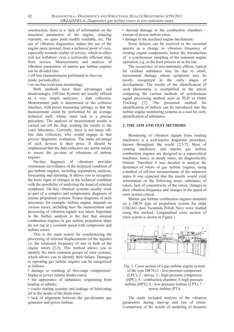
Marine gas turbine combustion engines mounted
on a DR76 type of propulsion system for ships
COGAG class Tarantula Polish Navy were studied
using this method. Longitudinal cross section of
rotor system is shown in Figure 1.
Fig. 1. Cross section of a gas turbine engine system
of the type DR76 (1 - low-pressure compressor
(LPC), 2 - drives, 3 - high-pressure compressor
(HPC), 4 - combustion chamber, 5-high pressure
turbine (HPT), 6 - low-pressure turbine (LPT), 7 -
power turbine (PT))
The study included analysis of the vibration
parameters during start-up and run of rotors.
Comparison of the results of modeling of dynamic

DIAGNOSTYKA - DIAGNOSTICS AND STRUCTURAL HEALTH MONITORING 3(59)/2011
GRZ DZIELA, Diagnostics gas turbine rotors in non stationary states
43
loads using FEM (Final Elements Methods) and
measurements of on the real object makes it
possible to take correct decisions and give the proper
diagnosis.
3. MODEL OF THE UNBALANCED ROTOR
Application of computer simulation to diagnose
the condition of turbine engine rotors should be used
already during the process of calculation and design,
which it is currently implemented. The problem
begins when the manufacturer does not provide this
kind of know-how in the technical specification for
the user. Such a situation arises in the case of
exported warships equipped with turbine engines.
While placing the engine, rotating parts are
assembled with great care,. Main objective is to
reduce unbalance in rotors. But even the best
procedures are not able to prevent factors, such as
the inadequacy of heat treatment or the difference of
thermal expansion of materials which may cause
slight unbalance in rotor, mentioned as residual.
Problems in the dynamics of Marine Gas Turbine
Engines (MGTE) are associated with the following
elements of the engine: rotors, bearings, bearing
brackets (bearing struts), engine block, the type of
construction, the terms of hydro-meteorological and
during sea trials and the aerodynamic parameters
inside the engine. Proper and stable work of MGTE
engine is mainly connected with these parameters.
Loss of energy in rotating machinery is manifested
in the form of loss of torque, a decrease in rotor
speed, exhaust temperature increase or intensity in
vibrations. Vibration energy dissipation is related to:
unbalancing of rotors, oversize tolerated shaft
misalignment, abrade of blade tips with the inner
roller, wear of axis and radial bearings, asymmetry
of elasticity and damping asymmetry of the rotor
and the gas-dynamic processes anomaly. Emission
of vibration yields a lot of information, including the
ability to diagnose the technical condition of rotors.
Vibration measurement, identification,
classification, mathematical analysis, including the
use of trend function, give information on the actual
technical state and allow the prediction of the wear
process in the future.
In the identification an important factor is to
compare the results of modeling with the results of
the measurements. Each rigid body has six degrees
of freedom, whereas the deformable objects have an
unlimited number of degrees of freedom. Rotating
machinery such as MGTE have a number of degrees
of freedom equal to the sum of all degrees of free
parts of the engine, minus the number of rigid nodes
connecting these elements. Each part of the engine
can be described by physical characteristics such as
stiffness and damping, obtained from vibration
measurements the actual object or model or the
modeling of the geometry and properties of
materials (the use of rigidly connected structures).
The use of a certain type of rigid object model
allows the use of the motion ordinary differential
equations. Deformable objects require the use of
partial differential equations. This second
assumption is much more complicated, but can help
to achieve to the actual object, especially when it's in
a wide range of engine speeds. This was the reason
for the choice of the second type of model turbine
engine. Diagram of diagnosis using the MGTE
model shown in Figure 2.
MGTE + MARINE
CONDITIONS
PHISICAL
MODEL OF
ENGINE
MATHEMATICAL
MODEL OF ENGINE
SOLUTIONS OF
EQUALIZATIONS
OF MOVEMENT
- FEM
COMPARATION OF RESULTS
Y (t)m Y(t)
Y(t)
RESULTS OF MEASUREMENTSRESULTS OF MODELING
Fig. 2. Scheme of diagnostics model MGTE
Residual unbalance may appear in all sections of
the rotor, however, two vectors of unbalance, at
both ends of the shaft, may represent the
replacement model. These vectors vary in values and
phase shifts. Such an FE model allows for dynamic
response to unbalance which in effect allows you to
compare modeling results with the reports of
vibration measurement. The most sensitive point in
the unbalance of GT rotor, with respect to
vibrations, is the measuring point on the front of the
generator exhaust bracket bearing the vertical
direction. This is the effect of the minimum thermal
expansion of the rigid support used for measurement
of radial vibrations at this point. The model is linear
so it is clear that response is directly proportional to
the value of unbalance The rotor is loaded
dynamically and statically from various sources [4].
Identification of the sources and their calculations of
the loads were a major problem during the modeling
and evaluation of the actual object's vibration.
Damage in the objects such as blades, have an
impact on changes in the moments of inertia of
rotating parts. This results in a shift of the main axis
of inertia, which is not parallel to the axis of
rotation. It is the main source of unbalance in the
form of vibrations of rotor. Implementation of the
mathematical model is difficult, mainly due to the
problems of determining the stiffness and damping
of supports and bearings at different temperatures -
Figure 3.
Shape of the axis deflection is defined as discrete
sets:
Set of static deflections – us; Set of dynamic deflections – ud.
Both sets depend on actual technical state of rotor and geometry, which can change through cracks and wanes of engine parts.
)()( tt ds uuu (1)
This equation is a discrete set of points of axis movement of the rotor. Taking into account the damping and stiffness of the support bearings, we
DIAGNOSTYKA - DIAGNOSTICS AND STRUCTURAL HEALTH MONITORING 3(59)/2011
GRZ DZIELA, Diagnostics gas turbine rotors in non stationary states
44
can demand that they are functions of temporary
positions, namely:
)()( ufcufk ikik (2)
C T PT
GT ENGINE BODY
BC
c G1
c G2
c BC
c G3 c G4
c H3 c H4c H2c H1
c H5
kH1kH2 kH3 kH4 kH5
kG4
kG3
kBC
kG2kG1
c k1 c k2 c k3 c k32
VESSEL HULL
kK32
kK3kK2kK1
LPClow pressure compressor
COMPRESSOR
HPThigh pressure compressor
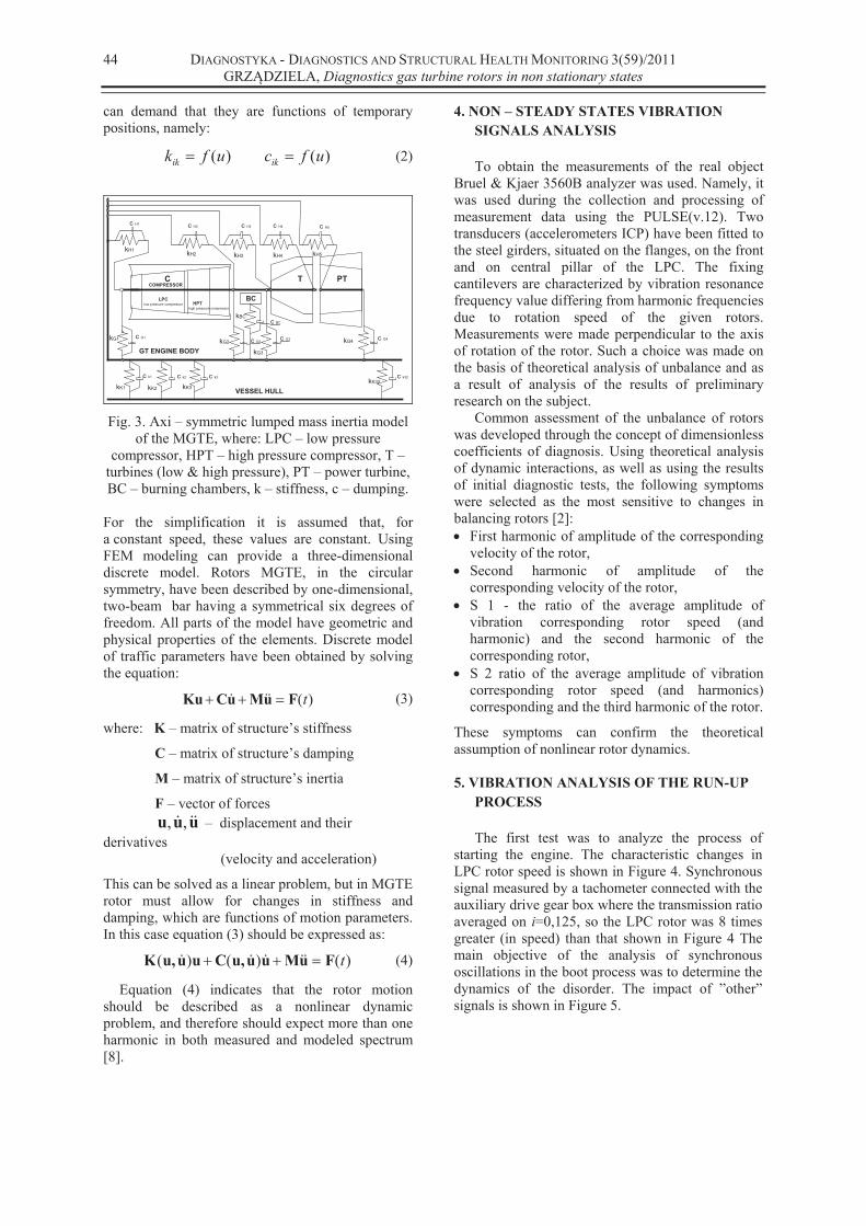
Fig. 3. Axi – symmetric lumped mass inertia model of the MGTE, where: LPC – low pressure
compressor, HPT – high pressure compressor, T – turbines (low & high pressure), PT – power turbine, BC – burning chambers, k – stiffness, c – dumping.
For the simplification it is assumed that, for a constant speed, these values are constant. Using FEM modeling can provide a three-dimensional discrete model. Rotors MGTE, in the circular symmetry, have been described by one-dimensional, two-beam bar having a symmetrical six degrees of freedom. All parts of the model have geometric and physical properties of the elements. Discrete model of traffic parameters have been obtained by solving the equation:
)(tFuMuCKu (3)
where: K – matrix of structure’s stiffness
C – matrix of structure’s damping
M – matrix of structure’s inertia
F – vector of forces uuu ,, – displacement and their derivatives (velocity and acceleration)
This can be solved as a linear problem, but in MGTE rotor must allow for changes in stiffness and damping, which are functions of motion parameters. In this case equation (3) should be expressed as:
)()()( tFuMuuu,Cuuu,K (4)
Equation (4) indicates that the rotor motion should be described as a nonlinear dynamic problem, and therefore should expect more than one harmonic in both measured and modeled spectrum [8].
4. NON – STEADY STATES VIBRATION
SIGNALS ANALYSIS
To obtain the measurements of the real object
Bruel & Kjaer 3560B analyzer was used. Namely, it was used during the collection and processing of measurement data using the PULSE(v.12). Two transducers (accelerometers ICP) have been fitted to the steel girders, situated on the flanges, on the front and on central pillar of the LPC. The fixing cantilevers are characterized by vibration resonance frequency value differing from harmonic frequencies due to rotation speed of the given rotors. Measurements were made perpendicular to the axis of rotation of the rotor. Such a choice was made on the basis of theoretical analysis of unbalance and as a result of analysis of the results of preliminary research on the subject.
Common assessment of the unbalance of rotors was developed through the concept of dimensionless coefficients of diagnosis. Using theoretical analysis of dynamic interactions, as well as using the results of initial diagnostic tests, the following symptoms were selected as the most sensitive to changes in balancing rotors [2]:
First harmonic of amplitude of the corresponding velocity of the rotor, Second harmonic of amplitude of the corresponding velocity of the rotor, S 1 - the ratio of the average amplitude of vibration corresponding rotor speed (and harmonic) and the second harmonic of the corresponding rotor, S 2 ratio of the average amplitude of vibration corresponding rotor speed (and harmonics) corresponding and the third harmonic of the rotor.
These symptoms can confirm the theoretical assumption of nonlinear rotor dynamics. 5. VIBRATION ANALYSIS OF THE RUN-UP
PROCESS
The first test was to analyze the process of
starting the engine. The characteristic changes in LPC rotor speed is shown in Figure 4. Synchronous signal measured by a tachometer connected with the auxiliary drive gear box where the transmission ratio averaged on i=0,125, so the LPC rotor was 8 times greater (in speed) than that shown in Figure 4 The main objective of the analysis of synchronous oscillations in the boot process was to determine the dynamics of the disorder. The impact of ”other” signals is shown in Figure 5.

DIAGNOSTYKA - DIAGNOSTICS AND STRUCTURAL HEALTH MONITORING 3(59)/2011
GRZ DZIELA, Diagnostics gas turbine rotors in non stationary states
45
Speed(Signal 1) - Input
Working : Input : 3D-time : Tachometer
0 2 4 6 8 10 12 14 16 18
0
100
200
300
400
500
600
700
800
900
1k
[s] (Time)
[RPM] Speed(Signal 1) - Input
Working : Input : 3D-time : Tachometer
0 2 4 6 8 10 12 14 16 18
0
100
200
300
400
500
600
700
800
900
1k
[s] (Time)
[RPM]
Fig. 4: Rotors LPC rotational speed characteristics
during run-up process
Autospectrum(Signal 3) - Input
Working : Input : 3D-time : FFT Analyzer
0 400 800 1,2k 1,6k 2k 2,4k 2,8k 3,2k
0
2
4
6
8
10
12
14
16
18
[Hz]
[m/s][s] (Time)
232n
404n
702n
1,11u
1,93u
3,36u
5,32u
9,25u
16,1u
25,5u
44,3u
77,0u
122u
212u
368u
584u
1,01m
1,76m
Autospectrum(Signal 3) - Input
Working : Input : 3D-time : FFT Analyzer
0 400 800 1,2k 1,6k 2k 2,4k 2,8k 3,2k
0
2
4
6
8
10
12
14
16
18
[Hz]
[m/s][s] (Time)
232n
404n
702n
1,11u
1,93u
3,36u
5,32u
9,25u
16,1u
25,5u
44,3u
77,0u
122u
212u
368u
584u
1,01m
1,76m
Fig. 5. Synchronous spectra of the velocity of
vibration during run-up process with using the band
– pass filter of 0,1Hz – 3,2 kHz range
The boot process started at the point t=7 seconds (see Figure 5), so all recorded vibration signals recorded from the start point contained the signals coming from other sources, i.e. non-rotating motor or frequency of its vibrations or a combination thereof. This allows to identify the main "other"
signals, such as: f1 = 305 Hz, f2 = 600 Hz, f3 = 1.6
kHz, and f4 = 2 kHz. which are associated with
sources outside the engine. The highest signal
during the boot process is the rotor speed and
harmonic vibrations, but in Figure 5 it is not clearly
visible due to the lack of a synchronous signal
tracking.
6. VIBRATION ANALYSIS OF THE SHUT-
DOWN PROCESS
Next test was associated with the analysis of
vibration parameters and related to the process runs
the motor rotor. Figure 6 shows autospectrum of the
velocity measured over the middle LPC bearing
using the order tracking procedure. Changes of
parameters are presented in the domain of time
function, in contrast to the boot process ,where the
dominant energy range of vibration signal was 1/2
harmonic - seen as a 4th order. The pressure drop of
the lubricating oil in the bearing caused an increase
in values ranging from displacement and slope
between the HPC and LPC rotor (rotating shafts
each other, while the shaft rotates within the LPC
HPC shaft - see Figure 1) and the typical dominance
of the subharmonics .
The increase in stiffness of the bearing system
confirms the existence of the harmonic “right-hand
branches” at the point where t (time) is equal to 4
seconds for the following rows: 4, 8 and 12, which
is associated with a pressure drop of lubricating oil
in the bearings.
Analysis of the dynamics of the turbine engine
rotor in transient states of a system PULSE should
be applied in both processes, ie start-up and run. The
start-up process helpsto recognize the "other"
signals, but the definition of dynamic functions is
very difficult due to the significant acceleration of
the rotors. Identifying characteristics of rotor system
dynamics is much more recognizable in the process
runs through the analysis of orders - Figure 7 and 8.
Fig. 6. Autospectrum of velocity of vibration in the
shut-down process with the use of order tracking
procedure, in the domain of time function
Analysis of the first harmonic (8th order) allows
to observe changes in dynamics as trends.
Application of the rotational speed function as
a field of analysis is the most important factor in the
study of the use of the Order Tracking procedure.
This allows you to detect changes in the natural
frequency, ignoring interference from the signals
originating from the thermodynamics processes of
turbine engines.
Subharmonics signal analysis is very useful in
the diagnosis of rotating machinery. Autospectrum
of 1 / 2 subharmonic's velocity range (considered in
the LPC rotor) indicates the individual
characteristics of particular rotors. The nature of
changes in order values in the rotor speed can be
thought of as an individual fingerprint of each rotor.
All changes to the technical condition of rotor
system, such as changes in stiffness and damping
parameters of alignment, or unbalance result in
changes in characteristics of subharmonics - Figures
7 and 8.

DIAGNOSTYKA - DIAGNOSTICS AND STRUCTURAL HEALTH MONITORING 3(59)/2011
GRZ DZIELA, Diagnostics gas turbine rotors in non stationary states
46
Autospectrum(Signal 3) - Input - slice1
Working : Input : tacho : Order Analyzer
400 600 800 1k 1,2k 1,4k 1,6k 1,8k 2k
0
100u
200u
300u
400u
500u
600u
700u
800u
900u
1m
[RPM] (Speed Signal 1)
[m/s] Autospectrum(Signal 3) - Input - slice1
Working : Input : tacho : Order Analyzer
400 600 800 1k 1,2k 1,4k 1,6k 1,8k 2k
0
100u
200u
300u
400u
500u
600u
700u
800u
900u
1m
[RPM] (Speed Signal 1)
[m/s]
Figure 7. Autospectrum of 8 order (I harmonic) of
velocity of vibration in the shut-down process of
LPC rotor stoppage
Autospectrum(Signal 3) - Input - 4 order V
Working : Input : tacho : Order Analyzer
400 600 800 1k 1,2k 1,4k 1,6k 1,8k 2k
0
400u
800u
1,2m
1,6m
2m
2,4m
2,8m
[RPM] (Speed Signal 1)
[m/s] Autospectrum(Signal 3) - Input - 4 order V
Working : Input : tacho : Order Analyzer
400 600 800 1k 1,2k 1,4k 1,6k 1,8k 2k
0
400u
800u
1,2m
1,6m
2m
2,4m
2,8m
[RPM] (Speed Signal 1)
[m/s]
Fig. 8. Autospectrum of 4 order (subharmonic) of
velocity of vibration in the shut-down process of
LPC rotor stoppage
7. CONCLUSIONS
All statistical analysis performed on the available
population of engines clearly show that the selected
parameters analyzed in the non-stationary processes
are the basis for predicting changes in the technical
condition of rotor system. Implementation of this
research turns out to be a credible verification of the
technology. Conclusions presented below have been
incorporated into operational diagnostics of marine
gas turbine engines:
• Synchronous measurement of vibration signals
during the boot and run processes enables us to
recognize symptoms of damage, including the
formation of resonance and changes in natural
frequencies and unbalanced rotors
• symptoms of S1 and S2 do not have sufficient
sensitivity for use in transient states due to the
instability of the processes and the need for
averaging the results,
• application of auto tracking and monitoring the
turbine engine rotor systems can identify a wide
range of typical damages, confirmed by the vibro-
acoustic diagnostics.
Application of the proposed methods of analysis
allows for the rational management of engine life
time even in the developed processes of
consumption. The analysis of test results obtained
gives the following conclusions:
the approach to the assess the technical
condition of gas turbine engines rotor system
allows to quickly detect changes in the permitted
unbalance and the maintained database enables
easier identification of the studied group of
engines
studies on trends in chosen parameters make it
possible to reliably detect changes in the value
of sensitive operational parameters during the
operation of the engine and to evaluate its
capabilities.
REFERENCES
[1] Charchalis A. Grzadziela A: Diagnosing of naval
gas turbine rotors with the use of vibroacoustic
parameters. The 2001 International Congress
and Exhibition on Noise Control Engineering.
The Hague, The Netherands 2001, pp. 268
[2] Downham E., Woods R.: The rationale of
monitoring vibration on rotating machinery,
ASME Vibration Conference, Paper 71 - Vib -
96, Sept. 8 - 10, 1971
[3] Grz dziela A.: Vibroacoustic method of shafting
coaxiality assessment of COGAG propulsion
system of a vessel, „Polish Maritime
Researches”, 1999, No 3, pp. 29–30.
[4] Grz dziela A: Diagnosing of naval gas turbine
rotors with the use of vibroacoustics parameters,
„Polish Maritime Researches”, 2000, No 3,
Gda sk 2000, pp. 14–17.
[5] Grz dziela A.: Vibration analysis of
unbalancing of marine gas turbines rotors,
„Mechanika”, 2004, t. 23, z. 2, pp. 187–194.
[6] Pedersen T. F., Gade S., Harlufsen H.,
Konstantin-Hansen H.: Order tracking in Vibro-
acoustic Measurements: A Novel Approach
Eliminating the Tacho Probe, „Technical
Review”, 2006, No 1, Brüel & Kjær, pp. 15–28.
[7] Krzyworzeka P., Adamczyk J., Cioch W., Jamro
E.: Monitoring of nonstationary states in
rotation machinery, Biblioteka Problemów
Eksploatacji, Wydawnictwo ITeE, Radom 2007.
[8] Rz dkowski R.: Dynamics of steam and gas
turbines, IFFM Publishers, Gda sk, 2009.
Andrzej GRZ DZIELA,
Ph. D is a Dean of the
Mechanical Electrical Faculty of
the Polish Naval Academy.
Vibroaco-ustics, technical
diagnostics and ships propulsion
construction are his professional
area. He is a V-ce President of
the Polish Association of the Technical Diagnostics.


