Download - DP rp-e307_2011-01
RECOMMENDED PRACTICE
DET NORSKE VERITAS
DNV-RP-E307
DYNAMIC POSITIONING SYSTEMS - OPERATION GUIDANCE
JANUARY 2011

FOREWORDDET NORSKE VERITAS (DNV) is an autonomous and independent foundation with the objectives of safeguarding life,property and the environment, at sea and onshore. DNV undertakes classification, certification, and other verification andconsultancy services relating to quality of ships, offshore units and installations, and onshore industries worldwide, andcarries out research in relation to these functions.
DNV service documents consist of amongst other the following types of documents:— Service Specifications. Procedual requirements.— Standards. Technical requirements.— Recommended Practices. Guidance.
The Standards and Recommended Practices are offered within the following areas:A) Qualification, Quality and Safety MethodologyB) Materials TechnologyC) StructuresD) SystemsE) Special FacilitiesF) Pipelines and RisersG) Asset OperationH) Marine OperationsJ) Cleaner EnergyO) Subsea Systems
AcknowledgementsThis Recommended Practice (RP) is based on the DP Operation guidance of the Marine Technology Society(MTS) DP Technical Committee. As such it is composed by the input of a variety of industry stakeholders ofwhich DNV was only one. In addition, the recommendations are general and cover wide range of operationalsituations and conditions. It is therefore underlined that DNV retains the freedom to give recommendationsdifferent from those listed in this document for other projects covering specific operations needs, situations andconditions.In addition it is noted that the MTS document and hence the content of this RP, is open for additional input andcomments in order to include the latest developments and experiences on DP operations. These inputs andcomments shall be reflected in subsequent revisions of these documents.
The electronic pdf version of this document found through http://www.dnv.com is the officially binding version© Det Norske Veritas
Any comments may be sent by e-mail to [email protected] subscription orders or information about subscription terms, please use [email protected] Typesetting (Adobe Frame Maker) by Det Norske Veritas
This service document has been prepared based on available knowledge, technology and/or information at the time of issuance of this document, and is believed to reflect the best ofcontemporary technology. The use of this document by others than DNV is at the user's sole risk. DNV does not accept any liability or responsibility for loss or damages resulting fromany use of this document.

Recommended Practice DNV-RP-E307, January 2011 Contents – Page 3
CONTENTS
1. General.................................................................................................................................................... 51.1 Introduction...............................................................................................................................................51.2 References.................................................................................................................................................61.3 Definitions and abbreviations ...................................................................................................................82. Management Guidance.......................................................................................................................... 92.1 DP Related Documentation.......................................................................................................................92.2 DP Class..................................................................................................................................................112.3 DP FMEA ...............................................................................................................................................112.4 DP Capability Plots.................................................................................................................................122.5 DP Footprint Plots...................................................................................................................................122.6 Position Reference Systems and Sensors................................................................................................132.7 Recommended DP Control Modes for DP Activities .............................................................................132.8 Trials and Checklists...............................................................................................................................142.9 DP Operations Manuals ..........................................................................................................................152.10 Activity Operational Planning ................................................................................................................152.11 Communications .....................................................................................................................................162.12 DP Planned Maintenance........................................................................................................................162.13 DP Incidents............................................................................................................................................172.14 Reporting and Record Keeping...............................................................................................................172.15 Competence.............................................................................................................................................172.16 Manning ..................................................................................................................................................173. Operational guidance MODUs ........................................................................................................... 183.1 Introduction.............................................................................................................................................183.2 DP Operational Documentation..............................................................................................................183.3 DP Class..................................................................................................................................................213.4 DP FMEA ...............................................................................................................................................223.5 DP Capability Plots.................................................................................................................................243.6 DP Footprint Plots...................................................................................................................................253.7 Position Reference Systems and Sensors................................................................................................263.8 Recommended DP Control Modes for DP Activities .............................................................................313.9 Trials and Checklists...............................................................................................................................323.10 DP Operations Manuals ..........................................................................................................................343.11 Activity Operational Planning ................................................................................................................363.12 Communications .....................................................................................................................................393.13 DP Planned Maintenance........................................................................................................................393.14 DP Incidents............................................................................................................................................403.15 Reporting and Record Keeping...............................................................................................................413.16 Competence.............................................................................................................................................413.17 Manning ..................................................................................................................................................423.18 Intervention – Role of the DPO and Engineer ........................................................................................433.19 DP Footprint Plots - Worked Examples .................................................................................................463.20 Annual DP Trials Test Table Blank – DP MODU .................................................................................483.21 Example of SMO and WSOG.................................................................................................................484. Operations guidance Project/Construction Vessels .......................................................................... 534.1 Introduction.............................................................................................................................................534.2 DP Operational Documentation..............................................................................................................534.3 DP Class..................................................................................................................................................554.4 DP FMEA ...............................................................................................................................................564.5 DP Capability Plots.................................................................................................................................584.6 DP Footprint Plots...................................................................................................................................594.7 Position Reference Systems and Sensors................................................................................................604.8 Recommended DP Control Modes for DP Activities .............................................................................644.9 Trials and Checklists...............................................................................................................................654.10 DP Operations Manuals ..........................................................................................................................684.11 Activity Operational Planning ................................................................................................................694.12 Communications .....................................................................................................................................724.13 DP Planned Maintenance........................................................................................................................734.14 DP Incidents............................................................................................................................................734.15 Reporting and Record Keeping...............................................................................................................744.16 Competence.............................................................................................................................................754.17 Manning ..................................................................................................................................................76
DET NORSKE VERITAS

Recommended Practice DNV-RP-E307, January 2011Page 4 – Contents
4.18 Intervention – Role of the DPO and Engineer ........................................................................................764.19 DP Footprint Plots - Worked Examples .................................................................................................794.20 Annual DP Trials Test Table Blank – DP Project / Construction Vessel ...............................................814.21 Example of SMO and ASOG..................................................................................................................815. Operational guidance Logistic Vessels............................................................................................... 865.1 Introduction.............................................................................................................................................865.2 DP Operational Documentation..............................................................................................................865.3 DP Class..................................................................................................................................................895.4 DP FMEA ...............................................................................................................................................895.5 DP Footprint Plots...................................................................................................................................925.6 Position Reference Systems and Sensors................................................................................................935.7 Trials and Checklists...............................................................................................................................985.8 DP Operations Manuals ........................................................................................................................1005.9 Activity Operational Planning ..............................................................................................................1025.10 Communications ...................................................................................................................................1055.11 DP Planned Maintenance......................................................................................................................1055.12 DP Incidents..........................................................................................................................................1065.13 Reporting and Record Keeping.............................................................................................................1075.14 Competence...........................................................................................................................................1085.15 Manning ................................................................................................................................................1095.16 Intervention – Role of the DPO and Engineer ......................................................................................1095.17 DP Footprint Plots – Worked Examples...............................................................................................1125.18 Annual DP Trials Test Table Blank – DP Logistics Vessel .................................................................1145.19 Example of SMO and ASOG................................................................................................................114
DET NORSKE VERITAS
Recommended Practice DNV-RP-E307, January 2011 1. General – Page 5
1. General1.1 Introduction1.1.1 IntroductionThis Recommended Practice (RP) is based on the Dynamic Positioning (DP) Operation guidance of the MarineTechnology Society's DP Technical Committee.
1.1.2 ObjectiveThe objective of this RP is to provide a guidance for the safe and effective conduct and management of DPoperations, including the following:
— Manage, mitigate and reduce the exposure to, and potential of, DP related incidents.— Identify themes that need to be managed.— Provide a list of reference documents that address themes, whilst acknowledging that existing referenced
documents do not identify all elements adequately when viewed in isolation.
1.1.3 ScopeThe themes that have been identified and addressed in this document are:
— DP Class— FMEA/ FMECA— DP Capability— Position Reference Systems And Sensors— Required Modes— Trials And Checklists— Operation Manuals— Activity and Operational Planning— Communications— DP Planned Maintenance— DP Incidents— Reporting And Record Keeping— Competency— Manning— Operator Intervention – DPOs and Engineers.
1.1.4 Application This document is not meant to replace any rules, regulations or owners’ operational manuals. It is a compilationof existing guidance and practices gleaned from various sources in industry. It refers to standards and guidanceused within the industry and draws attention to them. It also incorporates additional information gleaned fromexperience and documents/ standards not in the public domain.This is not intended to be an all encompassing document covering all aspects of DP operations. It focuses on anumber of important DP operational themes, which, if effectively managed, will result in safer DP operationsand a reduction in exposure to DP related incidents.The guidance provided in this document is not directed at any particular category of DP operation or DP vessel.It is intended to apply to any DP operation undertaken by any type and class of DP vessel operating in supportof offshore oil and gas activities, Examples include Mobile Offshore Units (MOUs), ships, construction andlogistics vessels where dynamic positioning is used for, or aiding, station keeping.
1.1.5 Document structureThis document consists of five chapters of which the first chapter contains general information and the othersthe relevant guidance on dynamic positioning. This guidance is started with a focus on the general managementof DP operations in chapter 2. This chapter is followed by specific operational guidance of DP operations ofdifferent vessel types as follows:
— Ch. 3 – DP MODUs— Ch. 4 – DP Project/ construction vessels and barges— Ch. 5 – DP Logistics vessels.
Note: Examples for the vessels covered in Ch. 4 are pipelay, heavy lift, dive support, ROV andaccommodation support vessels. The logistic vessels of Ch. 5 are typically OSVs or crew boats).When logistics vessels are used as platforms to carry out project/ construction activities theyshould follow the guidelines for project/ construction vessel/ barges.
To fully appreciate the context of chapters 3 to 5 without the need to refer back and forth, the specificoperational guidance of these chapters is completed with the general information of chapter 2. For distinction,
DET NORSKE VERITAS
Recommended Practice DNV-RP-E307, January 2011 Page 6 – 1. General
the general information is printed in regular text, and the specific operational guidance is in italics and/orgrouped under Guidance notes.
1.2 References1.2.1 Reference to MTS documentsAs stated in the introduction is this recommended practice based on MTS DP Technical Committee’s DPOperation guidance. In detail this concerns the following:
— DP Operations Guidance Part 1 Ver. 1.0 Oct 12th 2010 (incl.input DNV Jan 18th 2010)— DP Operations Guidance Part 2 Appendix 2 Project/Construction Vessels, Ver. 1.0 Oct 12th 2010
(incl.input DNV Jan 18th 2010)— DP Operations Guidance Part 2 Appendix 2 Project/Construction Vessels, Ver. 1.0 Oct 12th 2010
(incl.input DNV Jan 18th 2010)— DP Operations Guidance Part 2 Appendix 3 Logistics Vessels, Ver. 1.0 Oct 12th 2010 (incl.input DNV Jan
18th 2010).
DET NORSKE VERITAS

Recommended Practice DNV-RP-E307, January 2011 1. General – Page 7
1.2.2 Other normative references
Source Title Revision No. and Date
DP Operations Content
IMO Guidelines for Vessels with Dynamic Positioning Systems
IMO MSC/Circ 6451994
Internationally recognized basis for the design, equipment, testing, verification and operation of DP vessels
Class Classification Society DP Equipment Rules, Survey Rules and associated rules.
ABS, DNV, LRS, GL, BV, KR, etc.,
2010
DP equipment, DP operations manuals, DP trials, DP surveys, DP certification and DP class notations
USCG Use of Dynamic Positioning (DP) by Offshore Supply Vessels (OSVs) for Oil and Hazmat Transfers
USCG D8 Policy Letter Ltr-01- 2003
DP classification guidance, DP operating guidance, DP training and certification guidance
IMCA Guidance on Failure Modes and Effects Analysis
M1662002
DP FMEA/FMECA
IMCA Methods of Establishing the Safety and Reliability of DP Systems
M04/042004
DP FMEA/FMECA
IMCA FMEA Management Guide M1782005
DP FMEA management
IMCA Guidelines for the Design and Operation of DP Vessels
M103Rev 1 2007
Design philosophies, DP FMEA, redundancy, annual DP trials, checklists, DP operations, communications, manuals, manning, training, DP capability plots
IMCA Standard Report for DP Vessels Annual Trials
M1391997
Reporting format for annual DP trials, DP auditor competency
IMCA A Guide to DP Related Documentation for DP Vessels
M109Rev 1, 2004
DP operations manual – TOC, DP documentation, vessel operations manual, planned maintenance
IMCA International Guidelines for the Safe Operation of DP OSVs
M182Rev 1, 2009
DP FMEA, annual DP trials, checklists, manning, DP capability plots, incident reporting and investigation, risk based approach to DP operations
IMO Guidelines for Dynamic Positioning (DP) Operator Training
IMO MSC/738 Rev 1, 2006
Internationally recognized guidance for DPO training and experience
IMCA The Training and Experience of Key DP Personnel
M117Rev 1, 2006
Training, experience and certification requirements, onboard Familiarisation for key DP personnel
NauticalInstitute
The Nautical Institute Dynamic Positioning Operator’s Certificate
January 2010 Revision
Detailed guidance on the implementation of NI’s internationally recognized DPO certification scheme
IMCA Station Keeping Incident Form for DP Vessels
2008 Incident report form for DP vessels (DP construction, OSVs, etc.)
IMCA Station Keeping Incident Form for DP Tankers, FPSO, etc.
2006 Incident report form for DP tankers, FPSOs, etc
IMCA DP Incident Reports – Annual Summary and Analysis – all years
1994 - onwards Useful analysis and summary of DP incidents submitted to IMCA by member company vessels
IMCA Specification for DP Capability Plots
M140Rev 1, 2000
DP capability plots, worst case failure
IMCA Guidance on Simultaneous Operations
M2032010
Simultaneous operations
IMCA Guidance on Operational Communications
M205, D0462010
General guidelines, diving operations, lifting operations
IMCA Guidelines for Annual DP Trials for DP Mobile Offshore Drilling Units
M1912008
Annual DP trials, guidelines for incremental annual DP trials
IMCA Common Marine Inspection Document (CMID)
Issues6 and 7
Inspection report format and TOC for inspection, inc., DP section in Issue 6
IMO International Safety Management (ISM) Code
ISM Code2002
International standard for the safe management and operation of ships and for pollution prevention
DNV DNV for Certification 3.322 – Competence of Dynamic Positioning Operators – Stationkeeping
October 2009 Detailed learning objectives for the training of DPOs in the mentioned subject.
DET NORSKE VERITAS

Recommended Practice DNV-RP-E307, January 2011 Page 8 – 1. General
1.3 Definitions and abbreviations
1.3.1 DefinitionsCompetence: Competence is the acquisition of knowledge, skills and abilities at a level of expertise sufficientto be able to perform in an appropriate work setting.DP System: The DP system consists of components and systems acting together to achieve reliable positionkeeping capability. The DP system includes the power system (power generation and power management),thruster system and DP control system. DP Control System: The DP control system consists of all control components and systems, hardware andsoftware necessary to dynamically position the vessel. The DP control system comprises computer systems,sensors, display systems, position reference systems and associate cabling and routeing. Worst Case Failure: The Worst Case Failure (WCF) is the identified single failure mode in the DP systemresulting in maximum effect on DP capability as determined through FMEA study.Worst Case Failure Design Intent: The Worst Case Failure Design Intent (WCFDI) is the single failure withthe maximum consequences that has been the basis of the design and operational conditions. This usuallyrelates to a number of thrusters and generators that can simultaneously fail.Redundancy Concept: The Redundancy Concept is the means by which the Worst Case Failure Design Intentis assured.Safest Mode: Safest Mode is the configuration that the vessel’s DP system should be set up and operated in soas to deliver the intent of the vessel’s DP class notation. The objective is that no single failure should result inexceeding the worst case failure. Each DP vessel has only one safest mode which is unique to that vessel.Safest Mode Of Operation: The Safest Mode of Operation (SMO) is generally a tabulated presentation of howto configure the vessel’s DP system, including power generation and distribution, propulsion and positionreference systems, so that the DP system, as a whole, delivers the intent of the vessel’s DP class notation. TheSMO table also sets out the operator actions should a required configuration not be met. Activity Specific Operating Guidelines: Activity Specific Operating Guidelines (ASOG) are generallypresented in tabulated format and set out the operational, environmental and equipment performance limitsconsidered necessary for safe DP operations while carrying out a specific activity. The table also sets outvarious levels of operator action as these limits are approached or exceeded. The ASOG will vary dependingon the activity and are unique to that activity.
Note: Where DP MODUs are carrying out well activities the nomenclature is changed to WSOG (WellSpecific Operating Guidelines).
Task Appropriate Mode: Task Appropriate Mode (TAM) is a risk based mode. Task Appropriate Mode is theconfiguration that the vessel’s DP system may be set up and operated in, accepting that a single failure couldresult in exceeding the worst case failure and could result in blackout or loss of position. This is a choice thatis consciously made. This mode may be appropriate in situations where it is determined that the risks associatedwith a loss of position are low and, where the time to terminate is low.
Example 1: A DP MODU may operate in this mode during times when Time to Terminate is short, and inSafest Mode, when Time to Terminate is long.
Example 2: A DP pipelay vessel may operate in this mode when more than 500 m from a surface or missioncritical subsea asset, and in Safest Mode when inside 500 m.
Thruster and Generator Operating Strategy (TAGOS): A document that provides informed guidance, usuallyderived from a review of the FMEA and if necessary, validation from personnel knowledgeable about vesselspecific information, on appropriate configurations of thrusters, generators and power distribution, andassociated constraints, so as to enable correct choices to be made to provide optimum level of redundancy. DP Capability Plots: DP Capability Plots define by theoretical calculation the vessel’s capability to maintainposition in various environmental conditions, (i.e. wind, seastate and current) and, where appropriate, takingaccount of certain external forces, such as pipe tension and, in various thruster/ power configurations, includingall thrusters running, loss of most effective thruster and following worst case failure.DP Footprint Plots: DP Footprint Plots are constructed, by observation onboard the vessel in real timeconditions. The plots are of the vessel’s DP station keeping performance and limitations in variousenvironmental conditions (wind, seastate and current) and in various thruster/ power configurations, includingall thrusters running, loss of most effective thruster and after worst case failure.
Note: It is acknowledged that DP Footprint Plots for DP MODUs may be less relevant in comparison toDP vessels used for other applications.Owing to their almost continuous work programs DP MODUs will rarely have the opportunity torecord DP Footprint Plots for degraded thruster configurations.
DET NORSKE VERITAS

Recommended Practice DNV-RP-E307, January 2011 2. Management Guidance – Page 9
Failure Mode Effect Analysis (FMEA): An FMEA is a systematic analysis of systems and sub-systems to alevel of detail that identifies all potential failure modes down to the appropriate sub-system level and theirconsequences. A FMECA is an extension of an FMEA that adds a risk assessment of each failure mode todetermine its criticality.Time to Terminate: Time to Terminate (TTT) is calculated as the amount of time required in an emergency tophysically free the DP vessel from its operational activity following a DP abort status and allowing it to bemanoeuvred clear and to proceed to safety.
Example: In case of a DP drilling vessel this may be the time needed to release from the wellhead. For a DPdiving vessel this may be the time needed for the diver(s) to return to the bell and make a seal sothat the vessel can move clear. The Time to Terminate is not fixed for the duration of a DPoperation but will vary according to the circumstances.
1.3.2 Abbreviations
AIS Automatic Identification SystemASOG Activity Specific Operating GuidelinesDGNSS Differential Global Navigation Satellite SystemDGPS Differential Global Positioning Satellite systemDP Dynamic PositioningDPO DP OperatorECR Engine Control RoomESD Emergency Shutdown SystemFMEA Failure Modes and Effects AnalysisFMECA Failure Modes and Effects and Criticality AnalysisGPS Global Positioning (satellite) SystemHIL Hardware in the LoopIMCA International Marine Contractors AssociationIMO International Maritime OrganisationIT Information TechnologyLBL Long BaselineMTTR Mean Time to RepairMRU Motion Reference UnitSIMOPS Simultaneous OperationsSMO Safest Mode of OperationSBL Short Base LineSSBL Super Short Base LineTAGOS Thruster and Generator Operating StrategyTAM Task Appropriate ModeTTT Time to TerminateVRU Vertical Reference UnitWSOG Well Specific Operating Guidelines
2. Management GuidanceThe themes in this chapter are addressed from a management perspective. They are covered in greater depthand at an operational level in chapters 3 to 5.
2.1 DP Related Documentation2.1.1 GeneralIt is recommended that DP vessel owners/ operators should maintain the documentation listed in the tablebelow and should develop and implement associated processes for the purposes of:
— ensuring the safe and effective management of the vessel in DP— ensuring the technical suitability of the vessel for each DP activity it is required to carry out— determining the configuration for the safest mode of operation and the task appropriate mode— understanding the vessel’s station keeping capabilities following the worst case failure— ensuring compliance with appropriate standards and guidelines— providing training and familiarization material to vessel crews.
2.1.2 Recommended DocumentationCurrent versions of the documents in the list below should be kept on board and, in addition, where feasible, atthe shore based centers of technical management. Documents that have been superseded should be clearlymarked and kept separate from current versions. Documents may be in electronic or, hard copy format or, both. Further guidance relating to the listed documents is given in appropriate sections later in this chapter.
DET NORSKE VERITAS

Recommended Practice DNV-RP-E307, January 2011 Page 10 – 2. Management Guidance
Note 1: It is acknowledged that DP Footprint Plots may be less relevant for DP MODUs than for other DPvessel types.
Note 2: Owners/ operators should keep adequate records and documentation relating to modifications andadditions that could have an effect on the DP system, especially interfaces between equipmentfrom different vendors. This is as relevant for equipment whose primary function lies outside theDP system, such as an Emergency Shutdown Systems (ESD), pipe tensioner systems and firemonitor systems as it is for DP equipment, such as propulsion, position references and sensors.All modifications and additions should be subjected to FMEA type analysis and undergo ProvingTrials type testing.
No. Document Guidance1 DP System FMEA or FMECA To be kept up to date, incorporating all modifications and additions
since original study, if not in the document itself, then by other traceable means. All records to be kept on board.
2 DP FMEA Proving Trials To be conducted to prove initial DP FMEA and at other times to prove modifications and additions to the DP system. DP FMEA Proving Trials should be repeated every five years. Findings and recommendations to be addressed in accordance with their criticality. All records to be kept on board.
3 Annual DP Trials To be conducted annually. Findings and recommendations to be addressed in accordance with their criticality. Previous trials reports and associated close out documentation to be kept on board.
4 DP Capability Plots Hard copy DP Capability Plots relevant to the vessel’s areas of operations to be readily accessible to DPOs at the DP control location.
5 DP Footprint Plots Hard copy DP Footprint Plots to be taken by DPOs and kept on board. See Note 1 at end of table.
6 Service reports concerning the DP system
Complete history of service reports to be kept on board
7 Details of all DP related modifications and additions
Records of all DP related modifications and additions to be kept on board complete with interface and testing information. See Note 2 at end of table.
8 Vessel audit reports and DP audits and inspection reports.
Complete history of all audit reports, DP audits and inspection reports, inc., findings and close outs to be kept on board
9 DP Operations Manual Vessel Specific DP Operations Manual1), to be readily accessible at the DP control location and used by the DPOs as a reference for conducting DP operations.
10 DP Incident Reports Records of all DP station keeping and other DP related incidents to be kept on board, inc., investigation records and close outs.
11 DP Mobilization/ DP Field Arrival/ Trials Procedures (Bridge and Engine Room)
Records of DP Mobilization Trials and DP Field Arrival Checklists to be kept on board for the period set by the owner/ operator and, where relating to a DP incident permanently stored in retrievable archives.
12 DP Location and Watchkeeping checklists(Bridge and Engine Room)
Records of all DP Location and Watchkeeping Checklists to be kept on board for the period set by the owner/ operator and, where relating to a DP incident, permanently stored in retrievable archives.
13 DP related drills and emergency response drills
Records of DP related drills and emergency response drills to be kept on board in retrievable archives.
14 DP fault log Records of all faults related to the DP system to be kept on board permanently in retrievable archives.
15 DP data logging Where the vessel has DP data logging facilities electronic records should be kept on board for the period set by the owner/ operator and, where relating to a DP incident, permanently stored in retrievable archives.
16 DP alarm printer readouts Hard copy records of the DP alarm printer readout to be kept on board for the period set by the owner/ operator and, where relating to a DP incident, permanently stored in retrievable archives.
17 DP familiarisation and competency records
All records relating to vessel specific DP familiarisation and competency for DPOs, engineers and electricians to be kept on board permanently in retrievable archives.
18 Résumés and vessel specific work records of all key DP personnel
Resumes of all key DP personnel, copies of certification and qualifications, records of DP watchkeeping hours to be maintained on board. Original DPO certificates and DP Log Books to be held by the DPOs onboard the vessel.
1) The vessel specific DP Operations Manual is additional to the DP control system manufacturer’s Operator Manual.
DET NORSKE VERITAS

Recommended Practice DNV-RP-E307, January 2011 2. Management Guidance – Page 11
2.2 DP ClassIt is recommended that DP vessels with the following DP equipment class notations are used for the followingactivities. We underline that these recommendation represent a typical minimum; e.g local conditions, harshenvironments, and/or specific regulations/ requirements from oil majors may require a higher DP equipmentclass.
Note 1: The vessel’s DP system should normally be set up and operated to deliver the intent of the DPclass notation. However, on occasion and after a proper assessment of the risks, the vessel may beset up in accordance with the requirements of the Task Appropriate Mode.
Note 2: For operations close to another vessel or installation the equipment class should be 3 or equivalent.Class 2 may be accepted based on considerations of procedures, equipment and consequenceanalysis.
Note 3: It is noted that there have been standards developed outside the IMO DP equipment classsystematics where an identical (or higher) level of redundancy has been realized based on adifferent philosophy and system approach.
2.3 DP FMEAThe DP vessel’s DP FMEA is the most important technical document in the list of required documents. Therequirement for a DP FMEA has its origins in IMO MSC/Circ 645 (1994) “Guidelines for Vessels withDynamic Positioning Systems”. These benchmarking guidelines provide the foundation for all subsequent DPrules, regulations and guidance issued by Class and other industry bodies, such as IMCA.The IMO Guidelines require all DP vessels to be subjected to survey and testing in accordance with IMO’sspecified guidelines. This includes initial and periodic complete survey and testing of all systems andcomponents required to keep position after single failures associated with the vessel’s assigned DP equipmentclass. The periodic component in the IMO Guidelines requires the complete survey and testing to be repeated everyfive years to ensure full compliance with applicable parts of the guidelines. In addition compliance with IMO Guidelines requires survey and testing after defects are discovered andcorrected and, after a DP related accident and, whenever significant repairs or alterations are carried out, so asto demonstrate full compliance with applicable parts of the guidelines. The IMO Guidelines do not make clear distinction between vessels of different DP equipment class.This IMO requirement has been interpreted by the DP community such that the survey requirement is met bya DP FMEA (or FMECA1)) and the testing requirement by DP FMEA Proving Trials. 1) Unless expressly stated in this Guidance document a FMECA is interchangeable with an FMEA.
Accordingly, all DP vessels of DP Class 2 or 3 are required to have a Class approved and stamped DP FMEAand DP FMEA Proving Trials. In addition to complying with the IMO Guidelines and the relevant DP rules of the vessel’s ClassificationSociety the DP FMEA should achieve the standards of detail and analysis contained in the following industryguidance;
— IMCA M166 “Guidance on Failure Modes and Effects Analysis”
Application on DP Minimum Recommended DP Equipment Class(See Notes below)
Remarks
Drilling 2 Diving 2 Pipelay 2 Umbilical Lay 2 Lifting 2 Accommodation 2 Shuttle Offtake 2 ROV Support (Open Water) 1 ROV Support (Close Proximity - Surface/ Subsea) 2
Floating Production 2 Seismic and Survey vessels (Open water- outside 500 m zone) ** ** Class in accordance with contractual
requirementsWell Stim 2* * Vessels of lesser Class may be used with the
appropriate structured risk identification and mitigation measures in place.
Logistics Operations 2*
DET NORSKE VERITAS
Recommended Practice DNV-RP-E307, January 2011 Page 12 – 2. Management Guidance
— IMCA M178 “FMEA Management Guide”.
IMCA M04/04 2004 “Methods of Establishing the Safety and Reliability of DP Systems”
Note: FMEAs are a requirement to obtain DP Class 2 and 3 notation. Whilst not stipulated as a classrequirement for DP 1 vessels owners/ operators are encouraged to subject their DP 1 vessels to theDP FMEA process.
Note: Particular attention should be paid in the DP FMEA to the interfaces between the DP system andother systems that have the potential to affect the DP system, such as where the vessel is fittedwith an Emergency Shut Down (ESD) system, pipe tensioner system or fire monitor system.
Key DP personnel, including the vessel Master, DPOs, Engineers and Electricians should have a detailedknowledge of the DP FMEA and should use the information provided to be fully informed about thecapabilities and limitations of the vessel’s DP system. The results from a DP FMEA, in particular issues related to the vessel’s worst case failure and significant singlepoint failures, should be used in the formulation of operational, emergency response and planning decisions.
2.4 DP Capability PlotsDP Capability Plots should be calculated for the vessel. Guidance is provided on DP Capability Plots in IMCAM140 Rev 1, “Specification for DP Capability Plots”.These theoretical plots are calculated from detailed information of the vessel’s hull and superstructure form andavailable thruster power. The calculations should use environmental data (seastate, wind and current)appropriate to the area in which the DP vessel is to operate. These plots should show the limiting wind speed 360 degree envelopes for the scenarios below, where eachpoint on the envelope represents the wind speed at which it is calculated that the vessel will be unable tomaintain position in DP. DP Capability Plots should include the following scenarios at current speeds of 0, 1 and 2 knots, or at othercurrent speeds that are representative of the location in which the DP vessel is to operate:
— Fully intact power generation and thrusters.— Loss of most effective thruster(s).— Following the worst case failure.
Note: The DP Capability Plots should be provided in a format that is intuitive to the user on board (e.g.Polar Plot).
2.5 DP Footprint PlotsDP Footprint Plots should also be produced on board. DP Footprint Plots are not theoretical. They are actualmeasurements of the vessel’s DP station keeping performance in the actual environmental conditions andthruster configuration at the time the plot was taken. DP Footprint Plots should be taken whenever opportunitiesarise, such as during standby periods, weather downtime or on arrival at the field. Plots should be taken for thethruster configurations used in the DP Capability Plots, i.e. fully intact, loss of most effective thruster(s) andafter worst case failure.Some DP systems have a software application that produces DP Footprint Plots electronically. DPOs can alsoproduce DP Footprint Plots by manual methods using a plotting sheet.DP Footprint Plots serve two main purposes.
— They provide a scatter plot of vessel positions at regular intervals around the required set position (thisshows accuracy of station keeping)
— They also provide comparison points on the limiting wind speed envelope given in the theoretical DPCapability Plots (this shows wind speeds at which it was seen that the vessel was unable to maintainposition, thus validating or contradicting the theoretical DP Capability Plots for the various thrusterconfigurations.)
DP Footprint Plots serve other purposes, including learning and familiarisation opportunities for DPOs and inproviding snapshots of vessel station keeping behaviour for specific locations and activities. Theoretical DP Capability Plots and DP Footprint Plots combine together to enhance knowledge andunderstanding of the vessel’s DP station keeping ability.
Note: DP Footprint Plots originated in harsh weather regions, such as in the North Sea. The plots areused to gain a better understanding of the vessel’s actual station keeping performance andlimitations in intact and, in various degraded thruster configurations, including worst case failure,whilst the vessel is being subjected to real environmental forces. It is acknowledged that DP Footprint plots may be of less relevance to DP MODUs.
DET NORSKE VERITAS

Recommended Practice DNV-RP-E307, January 2011 2. Management Guidance – Page 13
2.6 Position Reference Systems and SensorsThe DP vessel should be equipped with suitable position reference and sensors in accordance with the vessel’sDP class notation and operational requirements. Position reference systems should be selected with dueconsideration to operational requirements, both with regard to restrictions caused by the manner of deploymentand expected performance in working situations.Position reference systems comprise absolute and relative systems. An absolute system gives vesselgeographical position. A relative system gives vessel position in relation to a non-fixed reference. A relativesystem can be used as an absolute system if installed on a point that is a fixed geographical position. And, anacoustic absolute system can be used as a relative system if attached to a non-fixed asset. The following are the most common position reference systems in use.
Note 1: Class rules give minimum requirements for the number of position references. Where operationaluptime is one of the key success factors the benefit gained by consciously exceeding the minimumrequirements are to be evaluated. Other benefits of exceeding minimum requirements includegreater redundancy and improved station keeping performance.
Note 2: It could be debated that Taut Wire and Acoustic position reference systems are relative positionreference systems. For purposes of this document, absolute indicates that this position referencesensor is independent of another fixed or floating offshore structure.
Caution: Additional position reference systems should be based on different principles. It is generally notrecommended to use multiple (>2) satellite based systems in conjunction with other positionsreference systems as this may result in skewed weighting in favour of multiple satellite systems.
Caution: DP reference systems sensitive to interferences from the vessels radars, radios etc. should not beused during critical operations such as sub-sea operations.
2.7 Recommended DP Control Modes for DP ActivitiesThe DP vessel should be equipped with suitable DP modes and features with due consideration to operationalrequirements, both with regard to restrictions caused by the activity and performance criteria required toexecute the activity safely and successfully.The following selected DP control modes are relevant to specific DP activities.
Absolute DGNSS (DGPS and GLONASS)Acoustic (USBL, SBL, LBL)Taut wire (See Note 2)
Relative ArtemisLaser (e.g. Fanbeam, Cyscan)Radar (e.g. RADius, RadaScan)DARPS
Target Follow: Enables the DP vessel to follow a moving target and is used, for example, to follow an ROV along a pipeline.
Heavy Lift: Takes account of the effects of the load transfer on the mass of the vessel and the additional lateral force, normally by reducing gain and relaxing the DP controller.
External Force Compensation: Where the measured external force acting on the vessel, which is separate from the environment, is included in the DP calculation and treated as a force feed forward. This mode is used to account for pipe tensions in a pipe layer and hawser tension in a shuttle tanker.
Fire Monitor Compensation: Used to compensate for the varying forces exerted on vessel from the fire monitors.
Weathervane: Enables the DP vessel to rotate with the wind, current and waves around a fixed or moving point called the terminal point. Neither the heading nor the position of the DP vessel is fixed. The heading of the vessel is controlled to point towards the terminal point. The position of the vessel is controlled to follow a circle, called the setpoint circle, around the terminal point. This mode is appropriate for connected shuttle tanker/ FPSO operations.Caution: It is not uncommon for the term “weathervane” to be used to
denote “minimum thrust”, i.e. where the DP control system allows the vessel’s heading to rotate to minimize external forces acting on the vessel and thruster requirements. These terms should not be confused.
DET NORSKE VERITAS

Recommended Practice DNV-RP-E307, January 2011 Page 14 – 2. Management Guidance
2.8 Trials and ChecklistsA range of trials and checklists is to be provided for each DP vessel and implemented as a verification that thevessel’s DP system complies with and, is operated in accordance with, applicable standards and guidelines.These may be performed under survey from the class as being part of their scope. This verification process should confirm the failure modes and their effects on the systems and equipmentanalysed in the DP FMEA document (to include the Worst Case Failure) and the vessel’s station keeping abilityfollowing its Worst Case Failure. Owners/ operators should refer to the following list of trials and checklistswhen developing an appropriate regime for their own DP vessels. The list below is a typical list for a DP divesupport vessel. This may differ from the regime as defined by class.
DP FMEA Proving Trials: A series of tests used to prove expected effects of failure modes found in the FMEA desktop analysis. These tests should also include the testing of interfaces between different vendor systems and equipment. These tests should be conducted immediately following launching of a new build vessel and following modifications, additions, upgrades repairs.
Endurance Trials: (new build/ system modifications class requirement): To prove the operation of the DP system under load conditions for at least 4 hours without significant alarms of the DP system.
Annual DP Trials: A series of tests of fault and failure conditions relevant to the DP System. The tests should be designed to prove system redundancy, as defined in the DP FMEA, system and equipment functionality, to validate repairs and preventive maintenance, and test the operation of protection and detection devices and responses so as to demonstrate that the vessel’s DP system remains fit for purpose. Annual DP Trials should be performed at a specific once a year within 3 months of the anniversary of the previous year’s trials. Annual DP Trials also provide the opportunities for training of the vessel’s crew and enhancement of their knowledge of failure modes and their effects. Note: Experience has shown that, owing to heavy operational
demands, DP drilling units are not usually able to meet the above criteria for conducting Annual DP Trials at a specific time once a year. This has been recognized by the industry with publication of specific guidance relating to the conduct of Annual DP Trials for DP MODUs. This is given in IMCA M191, “Guidelines for Annual DP Trials for DP Mobile Offshore Drilling Units”. The guidance sets out a regime of annual testing that is conducted on an incremental basis throughout the year as opportunities arise but needs to be completed within a twelve month period.
DP Mobilization Trials: A series of tests to be carried out at the start of a contract, subject to client requirements, to demonstrate redundancy and functional limitations of the DP system.
DP Field Arrival Trials: A series of checks and tests that confirm satisfactory performance of the DP system and verify the set up mode of operation and DP functions.
DP Location Set Up Checklist: A series of checks to demonstrate that the vessel is properly set up for the location, in particular the satisfactory performance of the position reference systems.
Pre-Dive Checklist: A series of checks performed prior to commencing diving operations. Main and back up communication tests should be included in this process.
ECR Checklists: A series of checks and tests that verify that the vessel’s set up and configuration of systems and equipment meet the requirements of the necessary mode of operation as determined by the Safest Mode of Operation (SMO) and the DP Class or the Task Appropriate Mode (TAM).
500 m Checks: A series of checks and tests performed before entering the 500 m zone of an asset in which set up mode and functions are verified and confirmed. Approval is then obtained to operate in close proximity to the asset. Main and back up communication tests should be included in this process.
Watch Status/ 6 Hour Checklist: A series of checks and tests performed by the DPOs to verify and confirm the set up of the DP system prior to taking over the DP watch.
DET NORSKE VERITAS
Recommended Practice DNV-RP-E307, January 2011 2. Management Guidance – Page 15
2.9 DP Operations ManualsA vessel specific DP Operations Manual should be prepared for each DP vessel. The vessel specific DP Operations Manual is the most important operational document in the list of requireddocuments. The requirement for a manual has its origins in IMO MSC/Circ 645 (1994) “Guidelines for Vesselswith Dynamic Positioning Systems”. The IMO Guidelines require a series of checklists, test procedures and DP operating instructions to beincorporated into one manual. Each Classification Society has its own specific requirements for a DP Operations Manual, each with differentrequirements for content. The recommendations set out below address areas that are not necessarily required by class. They are based oncurrent industry practices. The manual should contain sufficiently detailed instruction and guidance to enable the vessel to be operatedsafely in DP and safely execute its intended activities. This will include a clear statement on the DP philosophyfor the vessel, the organisation, responsibilities and roles of key DP personnel, training and competency,watchkeeping and manning, vessel technical data and layout, vessel DP capabilities, operating limits, operatingmodes, the planning and preparation of DP operations, DP operating procedures, emergency procedures, DPincident handling and alert systems and vessel specific trials and checklists that apply uniquely to the vessel. The manual should specifically address operational interfaces between different vendor systems and equipmentto ensure that they are configured and operated properly. This should include interfaces between systems andequipment that are not part of the DP system but which may affect the DP system, such as EmergencyDisconnect Systems (EDS) on MOUs, tensioner systems on Pipelay vessels, etc.The vessel specific manual may also contain generic content, such as company policies, procedures andstanding orders.The manual should represent the way the vessel is operated in DP. For complicated power systems and/ orthruster configurations, it may be useful provide the operator with a thruster and generator operating strategy(TAGOS) to assist in the decision on what generators and thrusters to use for different circumstances anddifferent equipment availabilities. Guidance on the contents of vessel specific DP Operations Manuals is provided in the following IMCAguidelines, M103, M109, M117 (contingency training) and in class society DP rules.
2.10 Activity Operational PlanningIn recognizing that exposure to risks manifests itself during vessel operations it is recommended that activitiesperformed by DP vessels should be subject to planning and preparation. In planning and preparing for theactivities the following should be considered and, where appropriate, documented:
— Configuration for the Safest Mode of Operation (SMO) or, where appropriate, the Task Appropriate Mode(TAM).
— Preparation of the Activity Specific Operating Guidelines (ASOG), including onboard discussion with allrelevant stakeholders as part of the pre-project execution/ activity.
— Discussion to be included in pre-project execution readiness checklist. — Capabilities of the vessel, both intact and residual capability, following Worst Case Failure (WCF).— Limitations imposed by water depth.— Consequences of a loss of position and/ or heading.— Limitations imposed upon operations by residual capability.— SIMOPS and marine vessel interaction and consequences arising from change of status (Green to Blue,
Post DP Incident Trials: Tests performed to ensure that the corrective/ repair measures taken following a DP incident have properly addressed the causes of the incident and that the vessel’s DP system is in a safe and operable condition.
Post DP Modification Trials: A series of checks and tests that are used to determine the effects of modifications and/ or additions on the DP system and the vessel’s subsequent station keeping performance.
Hardware in the Loop (HIL) tests: Extensive testing of functionality, failures and performance by using advanced simulation techniques and embedded systems. It can be used in factory acceptance tests, sea trials, annual tests, periodical tests and testing after upgrades.Note: The nomenclature used for the trials and checklists listed
above is based on the guideline document, IMCA M112: “Guidelines for Auditing Vessels with DP Systems”. It is recognized that these trials and checklists could be given other titles.
DET NORSKE VERITAS

Recommended Practice DNV-RP-E307, January 2011 Page 16 – 2. Management Guidance
Yellow or Red).— The activity being performed and the necessary time to terminate to bring vessel to a safe position upon the
onset of failure.
Activities should include day to day operations, any specific operation relevant to the design of the vessel, aswell as any unique operations the vessel is called upon to perform.Appropriate measures should be in place to clearly identify critical tasks/ operational phases of the activity andto ensure that the vessel is set up in Safest Mode of Operation and operating within post WCF capability. Wherea decision has been made to operate in a TAM a separate ASOG covering TAM should be produced.
Note: The ASOG should be developed by extracting all the relevant information from detailed technicalreview of the vessel’s DP FMEA, operational manuals and project specific procedures. TheASOG should be validated on board.On a DP MODU, ASOGs are known as WSOGs. Some owners refer to it as WSOC (Well SpecificOperating Criteria).
2.11 CommunicationsThe vessel should be equipped with the appropriate primary and secondary equipment needed to communicatebetween all parties (stakeholders) whilst carrying out the intended task.Effective internal and external communications is a key tool to manage risk.Communications in this context include voice, visual (lights/ displays) and audible means (alarms). Means ofcommunication are not limited to the above but include integrated IT systems using wireless networktechnology that combine communications with other features, including AIS and DGNSS. Operational specific visual and voice communications should ensure that the pertinent information flowsbetween the key operating points as well as to and from assets and/ or other vessels that might be affected bythe operation being carried out. These operating points may be onboard the vessel as well as on other facilities involved with the activity.Communication protocols are to be set up to provide pertinent information regarding intent, current status ofplanned as well as unexpected events during the execution of the activity. Continuity of communications during foreseeable emergency situations should be taken into account. Communications should be taken into account when detailing the roles and responsibilities of key personnelduring the planning stages for the intended task, ensuring that a common working language and terminology isused at all times. Guidance on communications is provided in M103, M182 and M205.
Note: The importance of communication to be emphasized by incorporating into the ASOG.
2.12 DP Planned MaintenanceDP vessels should have a structured planned maintenance system that specifically addresses maintenance ofthe vessel’s DP system, equipment and support systems. Relevant guidance is given in IMCA M109.Planned maintenance should address all equipment that has an impact on the vessel’s station keepingcapabilities. This should include indirect components such as generator circuit breakers, bus tie breakers, etc.Maintenance should include regular cleaning, calibration, and testing of equipment as outlined inmanufacturer’s recommendations and industry guidelines.Records of planned and unplanned maintenance should be kept in an auditable format, either hard copy orappropriate electronic format. These records should include vendor service records as well as maintenanceperformed by vessel personnel. These records should be kept on board for the period specified by the owner/operator. A minimum number of required critical DP spares should be maintained on board. The critical spare inventoryshould be monitored via a formal inventory program that is closely linked to the planned maintenance system.This should assist in getting back to normal operating condition after equipment failure or DP incident.
Note: The client’s due diligence process is usually the main driver in the critical path to return to normaloperating condition. Typically, this also involves vendor support as well as the client’s DPconsultant.
Note: Maintenance on DP related equipment whilst conducting DP operations should be controlled bya documented permit to work system and should always take into consideration the potentialalteration of failure modes and increased criticality of failure consequences on DP capabilitiesand/ or redundancy.
Note: System upgrades and changes (hardware and software) are typically subject to class approval. Inaddition, parts replaced during maintenance may require certification by class.
DET NORSKE VERITAS

Recommended Practice DNV-RP-E307, January 2011 2. Management Guidance – Page 17
2.13 DP IncidentsDP vessels should be provided with and operate appropriate DP incident reporting, investigation and closingout procedures. This should be in accordance with vessel owner or operators’ and, if applicable, clients’processes. Documented records should be kept and be capable of auditing. Where SMO, TAM and ASOG are used as tools to manage DP operations a suggested approach is that, apartfrom the exceptions in the notes below, any reactive change of DP status from GREEN to YELLOW or REDshould be regarded as a DP incident, and should be reported, recorded and investigated.
Note: A change of status triggered by prearranged agreement between the Master, and senior onboarddecision makers, allowing the vessel to exceed environmental limits should not be regarded as aDP incident.
Note: An operator initiated change of status as a result of a conscious decision based on risk analysis ofthe circumstances where the trigger points have not been reached should not be regarded as a DPincident.
It is recommended that reactive YELLOW and RED DP incidents are investigated as soon as practicable afterthe DP incident and, where relevant, trials are carried out as part of the investigation process. The purpose of the investigation and the trials should be;
— to assist in identifying the root causes of the incident— to verify and validate that measures to address the root cause are effective— to validate that effective measures have not introduced any additional potential to cause failures (both
hidden and apparent).
In the event of the occurrence of a DP incident relating to the vessel’s configuration as described in the DPFMEA and other documents, it is suggested that the FMEA provider is involved in the incident investigation.This will facilitate lessons learnt to be implemented into the DP FMEA and proving trials program. Owners/ operators of DP vessels are encouraged to share lessons learned from DP incidents with the wider DPcommunity. DP systems and equipment vendors are also encouraged to do likewise and to share informationon unexpected faults, features and failures that are identified in operation. IMCA’s station keeping incidentreporting scheme provides a suitable channel for disseminating relevant information throughout the DP sector.
2.14 Reporting and Record KeepingOwners or operators of DP vessels should have an effective reporting and record keeping system. There should be a clear line of reporting DP related items onboard the DP vessel and between each departmentand this should involve key DP personnel. There should also be a clear line of reporting between the DP vesseland the company’s shoreside management. DP related records should be maintained onboard and, whereappropriate, at the company’s premises. The documents and records contained in Sec.2.1.2, should be accessible to key DP personnel and to otherinterested parties.DP vessels, on occasion, carry out activities which may be unique to project requirements. Records of theseactivities including pertinent information from Hazards and Risk Identification (HIRAs) should be made andkept onboard for future reference, both for training and familiarisation processes as well as for reference in caseof similar project requirements in the future.
2.15 Competence
Definition: Competence is the acquisition of knowledge, skills and abilities at a level of expertise sufficientto be able to perform in an appropriate work setting.
DP vessel owners/ operators should operate a structured competence assurance program that is applied to allkey DP personnel with special focus on ensuring vessel and task specific competence. Guidance is provided in M103, M117 (IMO738)Vessel specific competency should, as a minimum, be demonstrated in the following areas:
— Operational modes— DP FMEA familiarization— DP Operations Manual familiarization— Project/ activity requirements— Contingency plans, modes and drills.
2.16 ManningVessels must comply with the statutory requirements for safe manning. Additionally, for DP operations,manning should be in accordance with the following:
DET NORSKE VERITAS

Recommended Practice DNV-RP-E307, January 2011 Page 18 – 3. Operational guidance MODUs
DP Bridge Crew
EngineersThere should be sufficient licensed engineers on board for all expected operations. At least one licensed engineer should be available at all times, should be on watch during critical activities andshould have at least 6 months experience on similar equipment and operations. The engineer should be fully cognisant of DP operations, familiar with the vessel’s DP FMEA document andthe effects of failures of equipment relating to the position keeping of the vessel.In DP 2 or 3 operations, the engineer should be familiar with the general philosophy of redundancy as it relatesto split mechanical, electrical and ancillary systems.Electrician/ Electrical EngineerIf required on board, an electrician should have appropriate high voltage training/ certification, if applicable tothe vessel. As with vessel engineers, the electrician/ electrical engineer should have at least 6 monthsexperience on similar equipment and operations.The electrician should likewise be fully cognisant of DP operations, familiar with the vessel’s DP FMEAdocument and the effects of failures of equipment relating to the position keeping of the vessel.
Note: Where the minimum experience requirements cannot be met a risk based approach should betaken to determine the suitability of personnel and any additional support requirements forintended operations.For low risk operations guidance is provided in IMCA M182. If used, the guidance providedwithin this document should be validated against the risks.
3. Operational guidance MODUs3.1 IntroductionThis chapter contains DP operational guidance, specific for MODUs. For overview and full appreciation, thisinformation is completed with the general management information as already was given in the previouschapter. For distinction, the general information is printed in regular text, and the specific operational guidanceis in italics and/or grouped under Guidance notes.
3.2 DP Operational Documentation
3.2.1 GeneralIt is recommended that DP vessel owners/ operators should maintain the documentation listed in the tablebelow and should develop and implement associated processes for the purposes of:
— ensuring the safe and effective management of the vessel in DP— ensuring the technical suitability of the vessel for each DP activity it is required to carry out— determining the configuration for the safest mode of operation and the task appropriate mode— understanding the vessel’s station keeping capabilities following the worst case failure— ensuring compliance with appropriate standards and guidelines— providing training and familiarization material to vessel crews.
Operation Minimum Bridge Crew per shift Minimum ExperienceWhen undertaking critical activities in proximity to surface or sub surface structuresSee Note 1 below
2 unlimited DPOs on the bridge capable of operating the vessel both in DP and manual control. See Note 2 below.
Unlimited DPO with a minimum of 3 years experience on a vessel engaged in similar operations, at least 6 months of which should have been on the subject or sister vessel. Experience level should be documented and auditable.See Note 3 below
Note 1 Critical activities are those activities where the consequences of equipment failure or loss of position are greater than under normal operating circumstances. For example, critical activities on a DP dive support vessel would include those occasions where the Time to Terminate is long, such as when the diver is inside a welding habitat or where the diver’s worksite is inside the conductor tubes at a production facility.
Note 2 The Master should not be considered as one of the required unlimited DPOs for meeting the manning requirements since operating as such would negative affect the situational awareness required from his side.
Note 3 It is recognized that in practice, given the near term market conditions owners/ operators will be challenged to meet the recommended level of experience for DPOs. Owners/ operators should recognize the associated risk from inexperienced personnel and have plans in place to address them while striving to reach the recommended experience levels.
DET NORSKE VERITAS
Recommended Practice DNV-RP-E307, January 2011 3. Operational guidance MODUs – Page 19
3.2.2 Recommended DocumentationCurrent versions of the documents in the list below should be kept on board and, in addition, where feasible, atthe shore based centers of technical management. Documents that have been superseded should be clearlymarked and kept separate from current versions. Documents may be in electronic or, hard copy format or, both.
No. Document Management Guidance Operational Guidance
1 DP System FMEA or FMECA
To be kept up to date, incorporating all modifications and additions since original study, if not in the document itself, then by other traceable means. All records to be kept on board. See Note 1 at end of table
Modifications and additions should be covered by a MOC process that triggers updating the FMEA.
2 DP FMEA Proving Trials
To be conducted to prove initial DP FMEA and at other times to prove modifications and additions to the DP system. DP FMEA Proving Trials should be repeated every five years. Findings and recommendations to be addressed in accordance with their criticality. All records to be kept on board.
Modifications and additions that should be proven by testing include all those that have direct effect or, potential to affect the performance or redundancy of the DP system. This will include protective, detection and monitoring functions.
3 Annual DP Trials
To be conducted annually. Findings and recommendations to be addressed in accordance with their criticality. Previous trials reports and associated close out documentation to be kept on board.
The tests in the Annual DP Trials should be designed to prove system redundancy, as defined in the DP FMEA, system and equipment performance and functionality, to validate repairs and preventive maintenance, to test the operation of protection and detection devices and their response so as to demonstrate that the vessel’s DP system remains fit for purpose. The option exists for DP MODUs to carry out Annual DP Trials on an incremental basis in accordance with the IMCA M191.
4 DP Capability Plots
Hard copy DP Capability Plots relevant to the vessel’s areas of operations to be readily accessible to DPOs at the DP control location.
Capability plots to be validated/ recalculated, as required, to ensure that they are suitable for the environmental conditions where the DP operations are to take place, in particular in respect of current speeds. This requirement to validate/ recalculate applies also in cases where DP vessel performance is affected by operational constraints imposed by the activity, such as in the case of a pipelay vessel with horizontal loads.
5 DP FootprintsHard copy DP Footprint Plots to be taken by DPOs. See Note 1 at end of table.
DP Footprint Plots should be taken regularly in various power/ thruster combinations, including fully intact and worst case failure and also in various environmental conditions.
6Service reports concerning the DP system
Complete history of service reports to be filed and kept on board
There should be a process where the open items are highlighted, tracked and closed out.
7Details of all DP related modifications and additions
Records of all DP related modifications and additions to be kept on board complete with interface and testing information. See Note 2 at end of table.
A structured FMEA and Proving Trials approach should be used to integrate modifications and additions into the existing DP system and its associated equipment.New and modified software should be subjected to a thorough validation process, especially to avoid the acceptance of erroneous values. Known instances as examples pipe tensioner software that accepted a sudden increase of pipe tension from 100 t to 300 t (erroneous input), software for thruster control that increased the command to the thruster to match the faulty feedback.It is not enough to focus on the functionality of modifications and additions. It is equally important to fully understand the functional design spec and the dependencies and consequences of fault or failure.
8Vessel audit reports and DP audits and inspection reports.
Complete history of all audit reports, DP audits and inspection reports, including findings and close outs to be kept on board
There should be a process where the open items are highlighted, tracked and closed out.
DET NORSKE VERITAS

Recommended Practice DNV-RP-E307, January 2011 Page 20 – 3. Operational guidance MODUs
9 DP Operations Manual
Vessel Specific DP Operations Manual1), to be readily accessible at the DP control location and used by the DPOs as a reference for conducting DP operations.
It is recommended that owners/ operators develop a standardised table of contents for vessel specific DP Operations Manuals in their fleet.Modifications and amendments to the DP Operations Manual should be subject to MOC processes, including changes to vessel specific checklists.
10 DP Incident Reports
Records of all DP station keeping and other DP related incidents to be kept on board, including investigation records and close outs.
All DP incidents should be investigated to an extent that reflects the potential consequences of the incident.
11
DP Mobilization/ DP Field Arrival/ Trials Procedures (Bridge and Engine Room)
Records of DP Mobilization Trials and DP Field Arrival Checklists to be kept on board for the period set by the owner/ operator and, where relating to a DP incident permanently stored in retrievable archives.
DP Trials and Checklists should be vessel specific and be developed from detailed information contained in the DP FMEA. They should confirm vessel performance, particularly following worst case failure, and that the vessel’s DP system is set up properly and provides the required level of redundancy.
12
DP Location and Watchkeeping checklists(Bridge and Engine Room)
Records of all DP Location and Watchkeeping Checklists to be kept on board for the period set by the owner/ operator and, where relating to a DP incident, permanently stored in retrievable archives.
As above
13DP related drills and emergency response drills
Records of DP related drills and emergency response drills to be kept on board in retrievable archives.
DP drills can be developed from fault and single point failure scenarios addressed in the vessel’s DP FMEA.The drills should also cover extreme events that are outside the scope of the DP FMEA.The outcomes from these drills should be used in the development of DP emergency response procedures and used as training material for DP personnel. These records may be used in a cycle of continuous improvement.
14 DP fault logRecords of all faults related to the DP system to be kept on board permanently in retrievable archives.
DP faults should be recorded as soon as possible after they are discovered and action/ investigation taken appropriate to the potential consequences of the fault on the vessel’s station keeping ability.
15 DP Data Logging
Where the vessel has DP data logging facilities electronic records should be kept on board for the period set by the owner/ operator and, where relating to a DP incident, permanently stored in retrievable archives.
DP data loggers perform an important function in helping to determine root causes of faults or failures. It is recommended that DP data logging function is included as part of the DP system design spec, DP data loggers should be commissioned and operational before DP system Customer Acceptance Trials (CAT) are carried out. The DP data logger should be incorporated in the SMO and running at all times when in DP. If not, this should trigger an Advisory condition, i.e. BLUE.There should be specific procedures for the operation and analysis of output from the DP data logger. This should include clear instructions on how and where the records are kept. Retention of data logging data should not be limited by time.
No. Document Management Guidance Operational Guidance
DET NORSKE VERITAS

Recommended Practice DNV-RP-E307, January 2011 3. Operational guidance MODUs – Page 21
Note 1: It is acknowledged that DP Footprint Plots may be less relevant for DP MODUs than for other DPvessel types.
Note 2: Owners/ operators should keep adequate records and documentation relating to modifications andadditions that could have an effect on the DP system, especially interfaces between equipmentfrom different vendors. This is as relevant for equipment whose primary function lies outside theDP system, such as an Emergency Shutdown Systems (ESD), pipe tensioner systems and firemonitor systems as it is for DP equipment, such as propulsion, position references and sensors.All modifications and additions should be subjected to FMEA type analysis and undergo ProvingTrials type testing. In addition, modifications and additions are typically subject to class approvaland inspection.
3.3 DP ClassIt is recommended that DP vessels with at least the following DP equipment class notations are used for thefollowing activities. Regulations, contractual specifications and/ or harsh environmental or other localconditions may require a higher class.
16 DP alarm printer readouts
Hard copy records of the DP alarm printer readout to be kept on board for the period set by the owner/ operator and, where relating to a DP incident, permanently stored in retrievable archives.
Owners/ operators frequently require DP alarm printer readouts to be kept for the duration of each well and then destroyed, unless relating to a DP incident or contractual dispute.
17DP familiarisation and competency records
All records relating to vessel specific DP familiarisation and competency for DPOs, engineers and electricians to be kept on board permanently in retrievable archives.
Owners/ operators should implement an in-house DP competency assurance process for key DP personnel which is structured, systematic and progressive. It should be noted that DPO certification is only one element in the competency assurance process. Owners/ operators are recommended to make use of facilities and training programmes available to the DP sector, such as the Powersim program for advanced DPO training of power plant fault conditions, where DPOs are given detailed instruction and training in identifying and responding to power system faults. Examples include DPO intervention averting an underfrequency induced blackout on closed bus system by the DPO taking control of thrusters and biasing to increase load.
18Résumés and vessel specific work records of all key DP personnel
Résumés of all key DP personnel, copies of certification and qualifications, records of DP watchkeeping hours to be maintained on board. Original DPO certificates and DP Log Books to be held by the DPOs onboard the vessel.
1) The vessel specific DP Operations Manual is additional to the DP control system manufacturer's Operator Manual
No. Document Management Guidance Operational Guidance
DET NORSKE VERITAS

Recommended Practice DNV-RP-E307, January 2011 Page 22 – 3. Operational guidance MODUs
Note 1: The vessel’s DP system should normally be set up and operated to deliver the intent of the DPclass notation. However, on occasion and after a proper assessment of the risks, the vessel may beset up in accordance with the requirements of the Task Appropriate Mode.
Note 2: For operations close to another vessel or installation the equipment class should be 3 or equivalent.Class 2 may be accepted based on considerations of procedures, equipment and consequenceanalysis.
Note 3: It is noted that there have been standards developed outside the IMO DP equipment classsystematics where an identical (or higher) level of redundancy has been realized based on adifferent philosophy and system approach.
Guidance note:A detailed risk analysis will be required if the vessel is to operate in a task appropriate mode (TAM) that providesless redundancy than that provided by the vessel’s DP equipment class notation. The detailed risk analysis should consider the consequences of loss of position relevant to the activity.
---e-n-d---of---G-u-i-d-a-n-c-e---n-o-t-e---
3.4 DP FMEAThe DP vessel’s DP FMEA is the most important technical document in the list of required documents. Therequirement for a DP FMEA has its origins in IMO MSC/Circ 645 (1994) “Guidelines for Vessels withDynamic Positioning Systems”. These benchmarking guidelines provide the foundation for all subsequent DPrules, regulations and guidance issued by Class and other industry bodies, such as IMCA.The IMO Guidelines require all DP vessels to be subjected to survey and testing in accordance with IMO’sspecified guidelines. This includes initial and periodic complete survey and testing of all systems and componentsrequired to keep position after single failures associated with the vessel’s assigned DP equipment class.The periodic component in the IMO Guidelines requires the complete survey and testing to be repeated everyfive years to ensure full compliance with applicable parts of the guidelines. In addition compliance with IMO Guidelines requires survey and testing after defects are discovered andcorrected and, after a DP related accident and, whenever significant repairs or alterations are carried out, so asto demonstrate full compliance with applicable parts of the guidelines. The IMO Guidelines do not make clear distinction between vessels of different DP equipment class.This IMO requirement has been interpreted by the DP community such that the survey requirement is met bya DP FMEA (or FMECA1)) and the testing requirement by DP FMEA Proving Trials.1) Unless expressly stated in this Guidance document a FMECA is interchangeable with an FMEA.
Accordingly, all DP vessels of DP Class 2 or 3 are required to have a Class approved and stamped DP FMEAand DP FMEA Proving Trials.
Application on DP Minimum Recommended DP Equipment Class
(See Note 1 below)
Remarks
Drilling 2
Diving 2
Pipelay 2 Umbilical Lay 2 Lifting 2 Accommodation 2
Shuttle Offtake 2 ROV Support (Open Water) 1 ROV Support (Close Proximity - Surface/ Subsea)
2
Floating Production 2 Seismic and Survey vessels (Open water- outside 500 m zone)
**** Class in accordance with contractual requirements
Well Stim 2* * Vessels of lesser Class may be used with the appropriate structured risk identification and mitigation measures in place. Logistics Operations 2*
DET NORSKE VERITAS

Recommended Practice DNV-RP-E307, January 2011 3. Operational guidance MODUs – Page 23
In addition to complying with the IMO Guidelines and the relevant DP rules of the vessel’s ClassificationSociety the DP FMEA should achieve the standards of detail and analysis contained in the following industryguidance;
— IMCA M166 “Guidance on Failure Modes and Effects Analysis”— IMCA M178 “FMEA Management Guide”— IMCA M04/04 2004 “Methods of Establishing the Safety and Reliability of DP Systems”.
Note: FMEAs are a requirement to obtain DP Class 2 and 3 notation. Whilst not stipulated as a classrequirement for DP 1 vessels owners/ operators are encouraged to subject their DP 1 vessels to theDP FMEA process.
Note: Particular attention should be paid in the DP FMEA to the interfaces between the DP system andother systems that have the potential to affect the DP system, such as where the vessel is fittedwith an Emergency Shut Down (ESD) system, pipe tensioner system or fire monitor system.
Key DP personnel, including the vessel Master, DPOs, Engineers and Electricians should have a detailedknowledge of the DP FMEA and should use the information provided to be fully informed about thecapabilities and limitations of the vessel’s DP system. The results from a DP FMEA, in particular issues related to the vessel’s worst case failure and significant singlepoint failures, should be used in the formulation of operational, emergency response and planning decisions.
Guidance note:These Guidance Notes on DP FMEAs are intentionally brief and gives a cursory overview of the underpinningphilosophy, analytical processes and the technical content of a DP FMEA. Relevant IMCA guidance, referred to inthis section, should be consulted to gain a more detailed understanding. A DP FMEA should encompass the following:
— identify worst case failure design intent (WCFDI) and worse case failure (WCF)— identify the equipment or subsystem, mode of operation and the equipment— Identify all potential failure modes and their causes— identify the significant single point failures— identify potential hidden failures— identify potential configuration errors— evaluate the effects on the system of each failure mode— Identify measures for eliminating or reducing the risks associated with each failure mode— identify trials and testing necessary to prove the conclusions— be updated after any major modifications and proving trials have been conducted— be subject to review and update as necessary, once every five years. The review should take account of new
equipment and hardware/ software updates, new developments in analysis and new knowledge acquired in theintervening period
— take account of action items from DP FMEA Proving Trials, Annual DP Trials, audits and incidents which havebeen or, are in the process of being, closed out
— take account of non DP systems/ auxiliary/ external systems that have interfaces with, and potential impact onDP and station keeping. These systems should be subjected to the FMEA and Proving Trials approach forsoftware, hardware and interfaces thus ensuring the integrity of the DP system and proper integration with DP
— take account of common mode failures that are otherwise liable to be overlooked, such as the effects ofhydrocarbon gas on engine control and safety systems, which can cause diesel engines to accelerate out ofcontrol resulting in catastrophic mechanical failure and potential for black out
— be presented as a narrative analysis of DP related systems and subsystems covering the above points (i.e.redundancy concept, hidden failures, configuration errors, etc) and be supported by sketches and drawings
— for DP Class 3 vessels, should consider the effects of fire and flood, not only from a compartment analysisperspective but also, where significant, at the subsystem level, e.g. the effects of fire and flood on ESD controllines and push buttons.
Note: Where the redundancy concept relies on inter-switching mechanisms, the reliability and effectivenessof these mechanisms should be proven and fully documented in the DP FMEA.
Note: The DP FMEA should contain an analysis of the DP control system I/Os to verify that it is consistentwith the redundancy concept and should be proved at DP FMEA Proving Trials.
Note: The DP FMEA for a DP MODU should address the ESD function, in particular the various issues relatingto the status of post activation battery power supplies (UPS). Appropriate guidance is given in section 6.6of IMCA M196, “Guidance on the Design, Selection, Installation and Use of UPS onboard Vessels”.
Note: The findings from a DP FMEA and Proving Trials should be categorised into A, B or C. Categoriesshould be clearly defined. Appropriate definitions are as follows;A For immediate attention. The failure effect exceeds worst case failure design intent or is noncompliant with specified rules and guidelines, e.g. Class rules. Improvement is required for classcompliance.B For attention when reasonably convenient. The failure effects equal worst case failure design intentbut there is an opportunity to reduce the failure effect as reasonable cost. A cost benefit analysis isrecommended.C For consideration. Comments and observations related to good practice.
DET NORSKE VERITAS

Recommended Practice DNV-RP-E307, January 2011 Page 24 – 3. Operational guidance MODUs
A FMECA is an extension of an FMEA that adds a risk assessment of each failure mode to determine its criticality.Criticality is derived from an assessment of the probability that a particular failure will occur combined with theseverity of the failure if it does occur.A DP FMECA should encompass all of the listed points in DP FMEA above and, in addition, include the following steps;
— determine the severity of each failure mode,— determine the probability of occurrence of each failure mode (using qualitative or reliable MTBF data),— determine and rank the criticality of the identified failure modes from highest to lowest,— determine a strategy for dealing with the ranked criticalities so that remedial measures are directed
appropriately in accordance with the criticality ranking.
The Criticality Analysis should be presented in tabulated form making using of risk matrices that comply withrecognised international standards such as those given in IMCA M166 or IEC 60812.
Note: The closing out of action items should be well documented and auditable.The following IMCA Guidelines address the above considerations in various levels of detail; M166, M178, M04/04and Annex.A DP FMEA should be referred to at the following times;
— conducting task based DP operational risk assessments, where key personnel involved should have detailedknowledge of the DP FMEA
— determining the DP vessel’s Safest Mode of Operation (SMO), e.g. where the unavailability of equipment mayreduce the vessel’s DP station keeping ability
— determining the DP vessel’s Well Specific Operating Guidelines (WSOG), e.g. where equipment performanceapproaches or exceeds predetermined limits
— determining the vessel’s Task Appropriate Mode, when applicable and warranted by the specific DP operations— developing planned maintenance schedules, taking account of the impact of taking systems or equipment out of
service— developing the vessel’s DP Operations and Emergency Response manuals and procedures— developing DP trials programs and checklists, ensuring that the single point failures identified in the DP FMEA
are covered in the trials and checklists.
Note to Owners In the case of newbuilds, if DP FMEAs are within the shipyard’s scope of supply, owners arerecommended to ensure that there are contractually binding agreements for the FMEA to meetspecifications set out in IMCA Guidelines, M166. M178, M04/04 and Annex and preferably becarried out by an independent third party DP FMEA practitioner.
Cautionary Note DP FMEAs that are solely focused on attaining class notation and class approval may notalways meet guidance standards stipulated in those IMCA Guidelines.
---e-n-d---of---G-u-i-d-a-n-c-e---n-o-t-e---
3.5 DP Capability PlotsDP Capability Plots should be calculated for the vessel. Guidance is provided on DP Capability Plots in IMCAM140 Rev 1, “Specification for DP Capability Plots”.These theoretical plots are calculated from detailed information of the vessel’s hull and superstructure form andavailable thruster power. The calculations should use environmental data (seastate, wind and current)appropriate to the area in which the DP vessel is to operate. These plots should show the limiting wind speed 360 degree envelopes for the scenarios below, where eachpoint on the envelope represents the wind speed at which it is calculated that the vessel will be unable tomaintain position in DP. DP Capability Plots should include the following scenarios at current speeds of 0, 1 and 2 knots, or at othercurrent speeds that are representative of the location in which the DP vessel is to operate:
— Fully intact power generation and thrusters.— Loss of most effective thruster(s).— Following the worst case failure.
Note: The DP Capability Plots should be provided in a format that is intuitive to the user on board (e.g.Polar Plot).
Guidance note:DP Capability Plots that do not cover Worst Case Failure are incomplete. DP Capability Plots that do not take intoaccount thruster interaction, (thruster-thruster, thruster-hull), thruster degradation and thruster barred zones areincomplete.Owners/ operators should note that it is important to provide a detailed scope of work to whoever is to generate theDP Capability Plots for the vessel. Experience has shown that those who generate the DP Capability Plots, such asthe DP system manufacturers, may not include the Worst Case Failure, unless specifically instructed to do so. This isparticularly relevant where the DP Capability Plots are included in the shipyard’s scope of supply for newbuilds. DP Capability Plots may have to be recalculated from time to time during the lifetime of a DP vessel. For example,the installation of new equipment, such as a crane or an accommodation module on deck will alter the vessel’s outline,
DET NORSKE VERITAS

Recommended Practice DNV-RP-E307, January 2011 3. Operational guidance MODUs – Page 25
which, in turn, will alter the wind effect on the vessel. In these circumstances the DP Capability Plots should be re-calculated to take account of the changes. DP Capability Plots may also have to be recalculated for thruster configurations where, due to unforeseen faults orfailures or, due to essential maintenance requirements, one or more thrusters are no longer available. Where notalready covered by existing calculations the revised DP Capability Plots should cover the following cases for the newthruster condition; i.e. the new fully intact condition, the new loss of most effective thruster(s) and the new worst casefailure condition.DP Capability Plots should be readily available to the DPOs at the DP control console. DPOs should consult DP Capability Plots as a matter of course whilst the vessel is conducting DP operations. DPOs should be fully familiar with the limits given in the DP Capability Plots for the fully intact thrusterconfiguration, for loss of most effective thruster and for worst case failure. DPOs should be careful when estimating the current force acting on the vessel and relating it to the DP CapabilityPlots. DPOs should be aware that the current force generated by the DP control system is the residual external forceacting on the vessel that cannot be measured. When wind speeds are low the attendant vessel, if available, could beused to estimate current by going into drift mode. DP Capability Plots should be used by DPOs and other key DP personnel as a reference in the planning phases whendetermining the vessel’s environmental operational limits for the WSOG. Where the DP Capability Plots show anundue level of heading limitations this may restrict the vessel’s operating range. This is not uncommon on vessels,such as DP tankers, that have good fore and aft thrust capability but limited thwartship capability. It should be remembered that DP Capability Plots are theoretical calculations and that, wherever possible,opportunities should be taken to validate the DP Capability Plots by taking DP Footprint Plots. See below.
---e-n-d---of---G-u-i-d-a-n-c-e---n-o-t-e---
3.6 DP Footprint PlotsDP Footprint Plots should also be produced on board. DP Footprint Plots are not theoretical. They are actualmeasurements of the vessel’s DP station keeping performance in the actual environmental conditions andthruster configuration at the time the plot was taken. DP Footprint Plots should be taken whenever opportunitiesarise, such as during standby periods, weather downtime or on arrival at the field. Plots should be taken for thethruster configurations used in the DP Capability Plots, i.e. fully intact, loss of most effective thruster(s) andafter worst case failure.Some DP systems have a software application that produces DP Footprint Plots electronically. DPOs can alsoproduce DP Footprint Plots by manual methods using a plotting sheet.DP Footprint Plots serve two main purposes.
— They provide a scatter plot of vessel positions at regular intervals around the required set position (thisshows accuracy of station keeping)
— They also provide comparison points on the limiting wind speed envelope given in the theoretical DPCapability Plots (this shows wind speeds at which it was seen that the vessel was unable to maintainposition, thus validating or contradicting the theoretical DP Capability Plots for the various thrusterconfigurations.)
DP Footprint Plots serve other purposes, including learning and familiarisation opportunities for DPOs and inproviding snapshots of vessel station keeping behaviour for specific locations and activities. Theoretical DP Capability Plots and DP Footprint Plots combine together to enhance knowledge andunderstanding of the vessel’s DP station keeping ability.
Note: DP Footprint Plots originated in harsh weather regions, such as in the North Sea. The plots areused to gain a better understanding of the vessel’s actual station keeping performance andlimitations in intact and, in various degraded thruster configurations, including worst case failure,whilst the vessel is being subjected to real environmental forces.
It is acknowledged that DP Footprint Plots may be of less relevance to DP MODUs.
Guidance note:Manual DP Footprint Plots are generated in the following manner.
— Use a proforma plotting sheet, comprising a 360 degree polar plotting diagram, vessel outline with thrustersindicated and space for vessel specific position reference systems and environmental data. Refer to plotting sheetsin Sec. 3.19.
— The vessel should be in auto DP. Record wind, waves and current on the plotting sheet, drawing appropriate vectors.— Record thruster configuration on the plotting sheet.— Record the rate of turn and speed of moves. It is suggested that the following values are applied, 10 deg/min and
0.3 m/sec, respectively, to prevent misleading results. — Observe position excursions from the intended position by the most appropriate means, plotting the vessel’s
position regularly, e.g. every 30 seconds.
DET NORSKE VERITAS

Recommended Practice DNV-RP-E307, January 2011 Page 26 – 3. Operational guidance MODUs
Sec.3.19 contains two worked examples. Both worked examples are for the same DP semi submersible drilling rig andin the same environmental conditions. Wind was 45 to 50 knots from 225 degrees with a corresponding wave heightof 6 m. Current was 1 coincident at 1 knot. Example 1 shows a DP Footprint Plot for the rig’s fully intact condition with all eight thrusters operational. The plotshows that the vessel was able to maintain position within +/- 2 meters with the wind and sea on the port quarter.Example 2 shows a DP Footprint Plot for the rig’s worst case failure condition with four thrusters operational. Theplot shows that the rig was unable to maintain position with the wind and sea on the port quarter. Example 2 - The known circumstances at the time of taking the DP Footprint Plot, of wind, wave height and thrusterconfiguration, in which the rig failed to maintain position, can be compared against the environmental envelopeplotted on the theoretical DP Capability Plot for worst case failure. They should be similar in that the DP CapabilityPlot should also show that vessel will be unable to maintain position in conditions where a 45 to 50 knots wind is onthe port quarter. If there is a significant difference between the two, particularly if the DP Capability Plot shows thatthe vessel can maintain position in the given condition, then it may be necessary to pull in the limiting wind envelopeon the DP Capability Plot to the upper wind speed determined by the DP Footprint Plot for these conditions.
Cautionary Note: The DP Footprint Plot positions will contain systematic position reference errors. ---e-n-d---of---G-u-i-d-a-n-c-e---n-o-t-e---
3.7 Position Reference Systems and SensorsThe DP vessel should be equipped with suitable position reference and sensors in accordance with the vessel’sDP class notation and operational requirements. Position reference systems should be selected with dueconsideration to operational requirements, both with regard to restrictions caused by the manner of deploymentand expected performance in working situations.Position reference systems comprise absolute and relative systems. An absolute system gives vesselgeographical position. A relative system gives vessel position in relation to a non-fixed reference. A relativesystem can be used as an absolute system if installed on a point that is a fixed geographical position. And, anacoustic absolute system can be used as a relative system if attached to a non-fixed asset. The following are the most common position reference systems in use:
Note 1: Class rules give minimum requirements for the number of position references. Where operationaluptime is one of the key success factors the benefit gained by consciously exceeding the minimumrequirements are to be evaluated. Other benefits of exceeding minimum requirements includegreater redundancy and improved station keeping performance.
Note 2: It could be debated that Taut Wire and Acoustic Position reference systems are relative positionreference systems. For purposes of this document, absolute indicates that this position referencesensor is independent of another fixed or floating offshore structure.
Caution: Additional position reference systems should be based on different principles. It is generally notrecommended to install multiple satellite based systems at the expenses of other systems.
Caution: DP reference systems sensitive to interferences from the vessels radars, radios etc. should not beused during critical operations such as sub-sea operations.
Guidance note:The reference system may be subject to contract specifications/ oil major requirements. Notwithstanding these,operational guidance on position reference systems and sensors is given in the table on the next page.
---e-n-d---of---G-u-i-d-a-n-c-e---n-o-t-e---
Absolute DGNSS (DGPS and GLONASS)Acoustic (USBL, SBL, LBL)Taut wire (See Note 2)
Relative ArtemisLaser (e.g. Fanbeam, Cyscan)Radar (e.g. RADius, RadaScan)DARPS
DET NORSKE VERITAS

Recommended Practice DNV-RP-E307, January 20113. Operational guidance MODUs – Page 27
Re
com
men
ded
Abso
lute
Pos
ition
Ref
eren
ce S
yste
ms
Reco
mm
ende
d Re
lativ
e Po
sitio
n Re
fere
nces
Sys
tem
s if i
n cl
ose
prox
imity
to a
n of
fsho
re
stru
ctur
e Se
nsor
s
App
licat
ion
on
DP
GPS
DG
NSS
(D
GPS
+
GLO
NA
SS)
(See
Not
e 2
belo
w)
SBL
(See
N
ote
1 be
low
)
USB
L/
SSB
L(S
ee
Not
e 1
belo
w)
LBL
(See
N
ote
1 be
low
)
Taut
W
ire
(See
N
ote 1
2 be
low
)
Min
N
umbe
r (S
ee
Not
e 3
belo
w)
Arte
mis
Lase
rR
adar
Gan
gway
D
AR
PSM
in F
ixed
pl
atfo
rm(S
ee N
otes
4,
5 &
6
belo
w*)
TLP/
SPA
R/
etc
< m
in
mov
emen
t(S
ee N
otes
4,
5 &
6 b
elow
*)
TLP/
SPA
R/
etc
> m
in
mov
emen
t(S
ee N
otes
4,
5 &
6 b
elow
*)
Gyr
os,
VR
Us a
nd
Win
d Se
nsor
s (S
ee N
ote
7 be
low
)D
rillin
gIf
in d
eep
open
wat
erR
edun
dant
- on
e du
al
freq
uenc
y
<700
m<7
00 m
>700
m<3
50 m
3Y
YY
NN
3 m
ixed
ab
s & re
l3
mix
ed ab
s &
rel
3 re
lativ
e on
ly3
Div
ing
NY
<700
m<7
00 m
>700
m<3
50 m
3Y
YY
NN
3 m
ixed
ab
s & re
l3
mix
ed ab
s &
rel
3 re
lativ
e on
ly3
Pipe
lay
NY
NN
NN
3Y
YY
NN
3 m
ixed
ab
s & re
l3
mix
ed ab
s &
rel
3 re
lativ
e on
ly3
Um
bilic
al L
ayN
YN
NN
N3
YY
YN
N3
mix
ed
abs &
rel
3 m
ixed
abs &
re
l3
rela
tive
only
3
Ris
er P
ull i
nN
Y<7
00 m
<700
m>7
00 m
<350
m3
YY
YN
N3
mix
ed
abs &
rel
3 m
ixed
abs &
re
l3
rela
tive
only
3
Lifti
ngN
Y<7
00 m
<700
m>7
00 m
<350
m3
YY
YN
N3
mix
ed
abs &
rel
3 m
ixed
abs &
re
l3
rela
tive
only
3
Acc
omm
odat
ion
NY
<700
m<7
00 m
>700
m<3
50 m
3Y
YY
YN
3 m
ixed
ab
s & re
l3
mix
ed ab
s &
rel
3 re
lativ
e on
ly3
Shut
tle O
ffta
keN
YN
NN
N3
YY
YN
Y3
mix
ed
abs &
rel
3 m
ixed
abs &
re
l3
rela
tive
only
3
RO
V S
uppo
rtN
Y<7
00 m
<700
m>7
00 m
<350
m2
NN
NN
N*
**S
ee N
ote
8 be
low
2
Floa
ting
Prod
uctio
n U
nit
NY
<700
m<7
00 m
>700
m<3
50 m
3N
NN
NN
NA
NA
NA
3
Wel
l Stim
N u
nles
s op
en w
ater
Y<7
00 m
<700
m>7
00 m
<350
m2
YY
YY
Y2
**
2
OSV
Sna
tch
Lifts
NY
<700
m<7
00 m
>700
m<3
50 m
2Y
YY
NN
12
mix
ed a
bs
and
rel
22
OSV
HA
ZMA
T Tr
ansf
er n
o qu
ick
disc
onne
ct
NY
<700
m<7
00 m
>700
m<3
50 m
3Y
YY
YN
23
mix
ed ab
s &
rel
3 re
lativ
e on
ly3
OSV
HA
ZMA
T Tr
ansf
er w
ith
quic
k di
scon
nect
NY
<700
m<7
00 m
>700
m<3
50 m
2Y
YY
YN
2*
*3
OSV
with
shaf
t ge
ns a
nd si
ngle
st
ern
thru
ster
NY
<700
m<7
00 m
>700
m<3
50 m
2Y
YY
YY
3*
*3
Win
d Tu
rbin
e in
stal
latio
nN
YN
AN
AN
AN
A2
NN
NN
NN
AN
AN
A2
Stan
dby
Ves
sels
YY
<700
m<7
00 m
>700
m<m
1N
NN
NN
NA
NA
NA
1 or
<
DET NORSKE VERITAS

Recommended Practice DNV-RP-E307, January 2011 Page 28 – 3. Operational guidance MODUs
Note 1: (Acoustics) – The acoustic LUSBL system is not included in the above table since it is acombination of USBL and LBL in one system, where the USBL is typically used to calibrate theLBL system. Standalone USBL systems are not the norm on DP drilling MODUs.The abbreviations, USBL and SSBL, are referred to in the above table. Although the abbreviationsdiffer they both refer to the same acoustic application although supplied by different vendors. It is recommended that, wherever possible, multiple acoustic systems are completely separatedand independent in all respects. For instance, this would require the use of separate andindependent hull transceivers.Owners/ operators should consider the advantages of acoustic positioning systems that have aninertial navigation input, such as the Kongsberg HAIN (Hydro Acoustic Inertial Navigation)system or Sonardyne’s AAINS (Acoustically Aided Inertial Navigation System) both of which can:- overcome the update rate limitations of speed of sound in water,- overcome the limitations on satellite based position reference systems brought upon by poorsatellite geometry.
Note 2: (Satellite Systems) – Satellite based systems that use a combination of signals from DGPS andGLONASS satellites provide enhanced redundancy over systems that use only a single satellite source.It is recommended that, wherever possible, multiple satellite based systems are completelyseparated and independent in all respects. For instance, this would require the use of differentmasts for the satellite antennae, separate cable routeing, different vendors and software. Wherethere is diversity of vendors and software it is recommended that the acceptance/ rejection logicis verified against the DP system manufacturer’s specifications. There have been incidents in thepast where diversity of vendors and software has resulted in loss of position due to the acceptanceof erroneous values within the software.Care should be taken at all times when using satellite based systems close to platforms. Guidanceis given in IMCA M141, “Guidelines on the Use of DGPS as a Position Reference in DP ControlSystems”, which highlights potential problems when within 150 m of a platform, such as themasking of GPS signals, masking of differential signals, radio interference and multipath. GoodDGPS close to structures should be considered as a bonus. In these locations DGPS should notbe considered as the primary position reference system.Where multiple DGPS systems are being used, consideration should be given to set each systemwith a different elevation mask. This is so that any jump in position that may occur when a satellitecomes into view will hit one DGPS before the next and will give the DPO some time to take action.Owners/ operators should consider the advantages of hybrid GNSS/ IMU positioning systems,such as the Kongsberg Seatex 4D system, where an inertial input is applied to the satellite basedsystem’s position calculation. This enhancement can fill the “holes” in positioning information inextraordinary and difficult conditions that otherwise might invalidate the satellite basedpositioning information, such as during times of scintillation and satellite ageing.
Note 3: (Absolute Systems) - Where multiple absolute systems are used it is recommended that they arebased on two different principles. Only where it is impractical to use systems based on differentprinciples may all be of the same type. This is of particular significance where DGPS is concernedwhere the satellite constellation provides a source for a common mode failure.
Note 4: (DP at non fixed Assets, e.g. FPSOs/ TLPs/ Spars) – When carrying out DP activities in closeproximity to or in conjunction with floating facilities it is strongly recommended that redundantrelative position reference systems are used. In these situations a mix of absolute and relativeposition reference systems for station keeping is to be used only after validating that movement ofthe floating structure, if any, does not impact station keeping. The DPOs must be extremelyvigilant when using a mix of absolute and relative position references and must be fully aware ofthe potential danger of diverging positioning information from both types of system.The minimum movement referred to in the table above refers to the actual measured movement offloating facility, e.g. FPSO/TLP/SPAR. To measure this movement the DP vessel should use anabsolute position reference system, such as DGPS, as the sole source for positioning informationand use the relative positioning system, such as RADius or Fanbeam, sited on the floating facilityto measure the fluctuations in its movement. It should also be noted that there are non fixed offshore facilities, such as TLPs and Spars wherean acoustic system, although normally considered as an absolute system, can be used as a relativesystem. This can be accomplished by installing the transponder/ beacon onto the submerged partof the TLP or Spar at an appropriate depth. Some TLPs and Spars are fitted with suitable subseabrackets or cradles for transponders/ beacons.
Note 5: (Absolute and Relative Systems) - When using DGPS/ GLONASS in a mix of absolute and relativeposition reference systems, in particular where there are two satellite based systems in a mix of
DET NORSKE VERITAS

Recommended Practice DNV-RP-E307, January 2011 3. Operational guidance MODUs – Page 29
three, users should bear in mind the possibility of the offshore structure blocking the satellitesignals and the consequences for station keeping.
Note 6: Wherever practical and feasible it is recommended that redundancy requirements are met bydiversity of suppliers, e.g. satellite based position reference systems from different manufacturersand differential signals from different sources. This applies equally to sensors such as gyrocompasses, VRUs and wind sensors.
Note 7: (Sensors) - Given the impact on heading/ position keeping it is recommended that vessels with anequivalent DP 2 class notation are provided with three gyro compasses, irrespective of therequirements of the applicable Classification Society DP rules. It should be noted that someClassification Societies, including ABS and DNV already require three gyro compasses for a DPclass 2 notation. Gyro compasses are normally fitted with a correction facility which inputs the vessel’s latitudeand speed. The effects of incorrect latitude or, more importantly, speed could result in asignificant error in output heading. It is therefore important to ensure that the latitude and speedcorrections are applied. Some systems use automatic input from GPS for these corrections. Thisis not recommended since there are a number of system errors that can result in undesiredheading changes. It is therefore recommended to use manual input of latitude and speed. Wind sensors are known to have suffered common mode failures, such as icing in higher latitudes,lightening, heavy rain and birds. All types of wind sensor are vulnerable, including ultrasonictypes. Where ultrasonic type wind sensors are fitted, the consequences for station keeping ofcommon mode failures, that affect these ultrasonic sensors, may be prevented by fittingmechanical wind sensors.DP vessels are frequently fitted with sensor systems, other than heading, motion and wind, whichhave a potential to affect the DP system and station keeping should there be an erroneous orinvalid input from them. These include draft sensors and pipelay tension sensors, where anerroneous or invalid input could result in extreme values and distortion of external forces andresult in large position excursion (drive off) from the desired set point position. There should bemeans of preventing erroneous values from being accepted by DP. An often practiced procedurewhich should prevent the above problems is to input these values manually and not to rely on theautomatic input function, if fitted. There should also be means of ensuring that erroneous valuesare prevented from being input manually.
Note 8: Where it is anticipated that due to operational requirements the DP vessel will require to bepositioned in close proximity to the non fixed facility and where the potential for shadowing ofDGPS exists, then redundancy in relative position reference sensors should be considered.
Note 9: Where, as is normal, multiple position references are in use by DP, the DPOs should monitor theweightings closely so as to ensure that no one system or set of systems is ‘hogging” the weighting.DPOs should recognise the potential dangers of using multiple satellite based systems (>2) in thesuite of position reference systems and that this could result in skewed ‘weighting” in favor ofsatellite systems at the expense of other position references. It is recommended that no more thantwo satellite based position reference systems be used to provide position solution as inputs into DP.
Note 10: New or retrofitted position references are sometimes interfaced into DP through inout designedfor other position references because the DP control system has not been designed to accept it.Examples of this are pseudo Artemis or pseudo acoustics. This practice is not recommendedunless accompanied by a detailed risk analysis and the residual risk, if any, is deemed acceptable.
Note 11: The practice of connecting survey and DP is not recommended. Where it is unavoidable, isolationbetween the systems is to be provided. DPOs should have ultimate control over the input. Allnecessary precautions should be taken to ensure that the vessel’s station keeping is not affectedand should be addressed in the FMEA.
Note 12: (Taut wires) – Care should be exercised when lowering or repositioning taut wire weights thatdivers and ROVs are alerted and are a safe distance from the seabed position. Taut wire weightsshould also be placed clear of pipelines, manifolds or other subsea assets. These subsea assetsshould be positively identified prior to positioning taut wire weights, e.g. by the ROV. Care shouldalso be taken that the taut wires are not fouled by other subsea lines or obstructions. It is possible for thruster wash to interact with a taut wire, acting as a strong current and causingposition instability. The thruster wash could be from own vessel or from another vessel close by.DPOs should be aware of the potential for this to occur. DPOs should be alert to the potential for taut wire weights to “skip” along the seabed and provideinaccurate positioning information. This can be avoided by ensuring that the tension control isproperly calibrated and operating within specified parameters and that the angle of wireinclination is kept as near to vertical as is possible and should not normally exceed 10 degrees.
DET NORSKE VERITAS
Recommended Practice DNV-RP-E307, January 2011 Page 30 – 3. Operational guidance MODUs
DPOs should also be aware of the potential for taut wire systems to become a “perfect” reference.This can have different causes, including the taut wire touching the side of own vessel or,otherwise being restricted in its movement, or by a faulty gimbal sensor. Most DP systems willdetect this fault. DPOs should ensure that the warning and alarm limits are properly set andoperational. The wires in use in modern taut wire systems are generally 5 mm or 6 mm in diameter. Weightsare in the region of 400 kg to 500 kg. Taut wires are quite highly stressed for marine wire ropesand are liable to breakage, particularly at points of weakness, such as continuous wear at the spoton the main sheave, continuous wear at any guide blocks and kinks or damage caused by poorspooling or where the wire is attached to the weight. The potential for wire breakage is reducedby regular inspection of the taut wire system and by slipping and cutting (cropping) the taut wireon a regular basis. Taut wire systems are known to suffer inaccuracies at water depths over 350 m, especially in highcurrent areas. Also at water depths under 350 m severe inaccuracies may occur. This should betaken into consideration when planning DP operations.
Note 13: It is important that software, parameters and values used by position reference systems arecompatible with the software and acceptance criteria used by the DP control system and that thisis verified by analysis and testing.
Attention is drawn to IMO MSC/Circ 645 where three MRU/VRUs are stipulated when vessel positioning isfully dependent on correct MRU/VRU signals.
Regional Requirements for DP Drilling UnitsOwners/ operators of DP drilling units should consider adopting the following standards for hydroacousticand satellite systems for deepwater DP drilling operations. The adoption of these standards should enable theDP drilling unit to operate anywhere in the world. Hydroacoustic Systems
— A minimum of two independent acoustic systems each one with internal redundancy as to transponders/beacons and transducers/ hydrophones capable of operating in maximum specified water depths with sucha configuration that allows a minimum of 0.5% of water depth in 95% of measurements. Each acousticsystem should have redundancy in the input of sensors (gyros and VRUs) and each transducer/ hydrophoneshould have redundancy in electrical supply.
— Acoustic systems operating in a master/ slave relationship or hot standby should be avoided. They shouldsimultaneously supply the DP controllers as totally independent position reference systems. Thedesignation of weight or deselection of a faulty position reference system should be performedautomatically by the DP controllers without DPO intervention.
Note: Inn deepwater applications where weighting adjustments by DPO may be required, detailedprocedures are to be provided.
— The unit (i.e. DP drillship or DP semi) should have a number of transponders/ beacons sufficient toconstitute submarine arrays capable of operating in the maximum water depth, including redundancy onthe bottom for the configuration of each operational mode and the back ups on the surface. Further,transponders should have an acoustic release function.
— The acoustic systems should have as additional function the primary actuation of the acoustic systemdriving the back up of BOP (with redundancy) via hull transducers. The BOP specific portable acousticunit should be used only in circumstantial situations, such as failure of the primary system or abandonmentof the platform.
Cautionary Note: where acoustic BOP systems are required, there is potential for interference by the useof equipment provided by multiple acoustic vendors.
— Consideration should be given to using USBL as a top down means of calibrating LBL systems. This willoptimise calibration times as well as improving accuracy.
Satellite Based Systems
— Two independent satellite positioning systems should be in operation, each with minimum accuracy ofthree meters. The primary receivers should have GPS dual frequency (L1/L2) in addition to one GLONASSreceiver. Each system should have double redundancy in the differential signal reception system asfollows; two different satellite systems (for example, Inmarsat and Spot Beam) and two different radiosystems (distinct frequencies and redundant transmitter stations with range covering the whole operationalscenario of the Unit (i.e. DP drillship or DP semi) (for example, IALA MF and UHF).
Note: Availability of the local radio system Infrastructure varies by region
DET NORSKE VERITAS

Recommended Practice DNV-RP-E307, January 2011 3. Operational guidance MODUs – Page 31
— Each satellite positioning system should have redundancy in the input of sensors (gyros and VRUs). — Antennae (both primary GPS and differential) should be situated in different places on the Unit spaced
apart in order to guarantee redundancy and minimize shadow sectors.— The satellite systems should provide the DP controllers with positioning reference information
simultaneously and independently.
3.8 Recommended DP Control Modes for DP ActivitiesThe DP vessel should be equipped with suitable DP modes and features with due consideration to operationalrequirements, both with regard to restrictions caused by the activity and performance criteria required toexecute the activity safely and successfully.The following selected DP control modes are relevant to specific DP activities.
Guidance note:The following table lists the recommended DP control modes that apply to different DP activities.
Note 1: The term “down weather” means that the vessel is on that side of the offshore structure where theenvironmental forces, acting on their own, would move the vessel away from the structure. Analternative term is that the vessel is on the “force off” side of the structure.
Note 2: The term “weathervane” has a specific meaning in the DP shuttle tanker industry.Note 3: The vessel specific DP Operations Manual should contain sufficient detail of these operating modes
and features.
Target Follow Enables the DP vessel to follow a moving target and is used, for example, to follow an ROV along a pipeline
Heavy Lift Takes account of the effects of the load transfer on the mass of the vessel and the additional lateral force, normally by reducing gain and relaxing the DP controller.
External Force Compensation
Where the measured external force acting on the vessel, which is separate from the environment, is included in the DP calculation and treated as a force feed forward. This mode is used to account for pipe tensions in a pipe layer and hawser tension in a shuttle tanker
Fire Monitor Compensation
Used to compensate for the varying forces exerted on vessel from the fire monitors.
Weathervane Enables the DP vessel to rotate with the wind, current and waves around a fixed or moving point called the terminal point. Neither the heading nor the position of the DP vessel is fixed. The heading of the vessel is controlled to point towards the terminal point. The position of the vessel is controlled to follow a circle, called the setpoint circle, around the terminal point. This mode is appropriate for connected shuttle tanker/ FPSO operations.
Caution: It is not uncommon for the term “weathervane” to be used to denote “minimum thrust”, i.e. where the DP control system allows the vessel’s heading to rotate to minimize external forces acting on the vessel and thruster requirements. These terms should not be confused.
Activity on DP Weather DP Control ModeDown Weather Only(See Note 1 below)
External Force Comp
Target Follow
Weather Vane(See Note 2 below)
Heavy Lift Mode
Drilling N N N N NDiving N N N N NPipelay N Y N N NUmbilical Lay N N N N NRiser Pull in (See Note 3) N Y Y N NLifting N N N N YAccommodation N N Y N NShuttle Offtake N N Y Y NROV Support N N Y N NFloating Production Unit NA N N Y NWell Stim if class 1 N N N NOSV Snatch Lifts if class 1 N N N NOSV HAZMAT Transfer no quick disconnect
Y N N N N
OSV HAZMAT Transfer with quick disconnect
N N N N N
OSV with shaft gens and single stern thruster
Needs to head into weather
N N N N
Standby Vessels Y if class 1 N N N N
DET NORSKE VERITAS

Recommended Practice DNV-RP-E307, January 2011 Page 32 – 3. Operational guidance MODUs
Note 4: The DPOs are to familiarize themselves with operational constraints/ requirements of these modes andfeatures.
Note 5: A detailed and documented risk assessment should be carried out when it is planned to perform any ofthe above activities without the recommended DP control mode.
Note 6: Where DP vessels, such as DP MODUs carrying out subsea construction activities, are engaged inactivities outside their normal scope they should do so using the recommended DP control mode. Thismay mean that the mode has to be installed in the DP control system.
---e-n-d---of---G-u-i-d-a-n-c-e---n-o-t-e---
3.9 Trials and ChecklistsA range of trials and checklists is to be provided for each DP vessel and implemented as a verification that thevessel’s DP system complies with and, is operated in accordance with, applicable standards and guidelines.Being part of their scope, these trials may be subject to survey and approval by class.This verification process should confirm the failure modes and their effects on the systems and equipmentanalysed in the DP FMEA document (to include the Worst Case Failure) and the vessel’s station keeping abilityfollowing its Worst Case Failure. Owners/ operators should refer to the following list of trials and checklistswhen developing an appropriate regime for their own DP vessels. The list below is a typical list for a DP divesupport vessel. This may be different from the regime as defined by class.
DP FMEA Proving Trials: A series of tests used to prove expected effects of failure modes found in the FMEA desktop analysis. These tests should also include the testing of interfaces between different vendor systems and equipment. These tests should be conducted immediately following launching of a new build vessel and following modifications, additions, upgrades repairs.
Endurance Trials: (new build/ system modifications class requirement): To prove the operation of the DP system under load conditions for at least 4 hours without significant alarms of the DP system.
Annual DP Trials: A series of tests of fault and failure conditions relevant to the DP System. The tests should be designed to prove system redundancy, as defined in the DP FMEA, system performance and equipment functionality, to validate repairs and preventive maintenance, and test the operation of protection and detection devices and responses so as to demonstrate that the vessel’s DP system remains fit for purpose. Annual DP Trials should be performed at a specific occasion once a year and within 3 months of the anniversary of the previous year’s trials. Annual DP Trials also provide the opportunities for training of the vessel’s crew and enhancement of their knowledge of failure modes and their effects. Note: Experience has shown that, owing to heavy operational demands,
DP drilling units are not usually able to meet the above criteria for conducting Annual DP Trials at a specific time once a year. This has been recognized by the industry with publication of specific guidance relating to the conduct of Annual DP Trials for DP MODUs. This is given in IMCA M191, “Guidelines for Annual DP Trials for DP Mobile Offshore Drilling Units”. The guidance sets out a regime of annual testing that is conducted on an incremental basis throughout the year as opportunities arise but needs to be completed within a twelve month period.
DP Mobilization Trials: A series of tests to be carried out at the start of a contract, subject to client requirements, to demonstrate redundancy and functional limitations of the DP system.
DP Field Arrival Trials: A series of checks and tests that confirm satisfactory performance of the DP system and verify the set up mode of operation and DP functions.
DP Location Set Up Checklist: A series of checks to demonstrate that the vessel is properly set up for the location, in particular the satisfactory performance of the position reference systems.
Pre-Dive Checklist: A series of checks performed prior to commencing diving operations. Main and back up communication tests should be included in this process.
ECR Checklists: A series of checks and tests that verify that the vessel’s set up and configuration of systems and equipment meet the requirements of the necessary mode of operation as determined by the Safest Mode of Operation (SMO) and the DP Class or the Task Appropriate Mode (TAM).
DET NORSKE VERITAS

Recommended Practice DNV-RP-E307, January 2011 3. Operational guidance MODUs – Page 33
Note: The nomenclature used for the trials and checklists listed above is based on the guidelinedocument, IMCA M112: “Guidelines for Auditing Vessels with DP Systems”. It is recognizedthat these trials and checklists could be given other titles.
Guidance note:Annual DP Trials for MODUs The following guidelines apply to the development and the conduct of Annual DP Trials for a DP MODU inaccordance with guidance contained in IMCA M191. M191 guidance describes a regime of annual testing that isconducted on an incremental basis throughout the year as opportunities arise but needs to be completed within atwelve month period. M191 also recognises the contribution that planned maintenance systems can play in verifyingthe status and performance of certain DP equipment throughout the year.M191 gives the purpose of Annual DP Trials as follow; “...... to improve the DP system safety and performance by testing faults and failure conditions important to DP safetyto prove the ability of the vessel to keep position after single point failures associated with the IMO equipment classand to verify the FMEA requirements. When faults identified during the year on similar DP MODUs are determinedto be feasible on the vessel then additional tests should be incorporated in the trials program.”Using the above quotation as the background, owners/ operators should use the vessel specific DP FMEA andProving Trials as the principal source for developing the Annual DP Trials program.
Note: The remainder of this subsection on Annual DP Trials is on hold pending formal publication of IMCAguidance on Annual DP Trials which is under development at the time of preparing this document.Guidance will be provided in a subsequent revision of this document.
DP Mobilization TrialsThese trials should be carried out by the vessel’s crew as part of the mobilizing program prior to the start of a newproject. The tests carried out at these trials are less than are carried out at Annual DP Trials but more than at DPField Arrival Checks. The tests should confirm the vessel’s redundancy concept and station keeping performance afterworst case failure. They should also provide assurance of the integrity of the vessel’s DP system and the vessel’soperational limitations.
DP Field Arrival ChecksThese checks should be carried out on arrival at the field. The purpose of these checks is to ensure satisfactoryoperation of the DP system and should include a full functional check of the operation of all thrusters and powergenerating equipment and systems, auto DP and all control modes. The checks should also ensure that the DP systemis set up properly.
500 m Checks500 m checks are not normally applicable to DP MODUs. All OSVs and others vessels should undertake 500 mchecks. Only vessels engaged in support activities to remain within the 500 m zone of the DP MODU. The 500 m zoneis not to be used as a standby location unless required to support a specific activity.
Watch Status/ 6 Hour ChecklistThe purpose of these checks is to record the status of the DP system and configuration. The checks should verify thatthe vessel’s station keeping performance at the working location is satisfactory and, in particular, that the positionreference systems are properly set up and operating satisfactorily. No testing is carried out. DPOs should completethe checklist prior to taking over the watch, not during the first few minutes of the watch.
Post Modification/ Upgrade DP TrialsIt is essential to ensure that any modification, change or upgrade to the DP system is fully tested and that the vessel’sredundancy concept has not been affected. Testing should follow on from a detailed FMEA type analysis of the changewhich should be fully documented.
500 m Checks: A series of checks and tests performed before entering the 500 m zone of an asset in which set up mode and functions are verified and confirmed. Approval is then obtained to operate in close proximity to the asset. Main and back up communication tests should be included in this process.
Watch Status/ 6 Hour Checklist:
A series of checks and tests performed by the DPOs to verify and confirm the set up of the DP system prior to taking over the DP watch.
Post DP Incident Trials: Tests performed to ensure that the corrective/ repair measures taken following a DP incident have properly addressed the causes of the incident and that the vessel’s DP system is in a safe and operable condition.
Post DP Modification Trials: A series of checks and tests that are used to determine the effects of modifications and/ or additions on the DP system and the vessel’s subsequent station keeping performance.
Hardware in the Loop (HIL) tests
extensive testing of functionality, failures and performance by using advanced simulation techniques and embedded systems. It can be used in factory acceptance tests, sea trials, annual tests, periodical tests and testing after upgrades.
DET NORSKE VERITAS
Recommended Practice DNV-RP-E307, January 2011 Page 34 – 3. Operational guidance MODUs
The following example shows the inherent dangers of failing to take proper account of change. In this example theinstallation of a more up to date and faster OS computer resulted in the new computer re-booting too early and failingto “ride through” the brief power interruption that resulted from the activation of a changeover relay. This resultedin the temporary loss of that operator station.
---e-n-d---of---G-u-i-d-a-n-c-e---n-o-t-e---
3.10 DP Operations ManualsA vessel specific DP Operations Manual should be prepared for each DP vessel.The vessel specific DP Operations Manual is the most important operational document in the list of requireddocuments. The requirement for a manual has its origins in IMO MSC/Circ 645 (1994) “Guidelines for Vesselswith Dynamic Positioning Systems”.The IMO Guidelines require a series of checklists, test procedures and DP operating instructions to beincorporated into one manual.Each Classification Society has its own specific requirements for a DP Operations Manual, each with differentrequirements for content.The recommendations set out below address areas that are not necessarily required by class. They are based oncurrent industry practices.The manual should contain sufficiently detailed instruction and guidance to enable the vessel to be operatedsafely in DP and safely execute its intended activities. This will include a clear statement on the DP philosophyfor the vessel, the organisation, responsibilities and roles of key DP personnel, training and competency,watchkeeping and manning, vessel technical data and layout, vessel DP capabilities, operating limits, operatingmodes, the planning and preparation of DP operations, DP operating procedures, emergency procedures, DPincident handling and alert systems and vessel specific trials and checklists that apply uniquely to the vessel. The manual should specifically address operational interfaces between different vendor systems and equipmentto ensure that they are configured and operated properly. This should include interfaces between systems andequipment that are not part of the DP system but which may affect the DP system, such as EmergencyDisconnect Systems (EDS(disconnect sequence)) on MODUs, tensioner systems on Pipelay vessels, etc.The vessel specific manual may also contain generic content, such as company policies, procedures andstanding orders.The manual should represent the way the vessel is operated in DP. For complicated power systems and/ orthruster configurations, it may be useful provide the operator with a thruster and generator operating strategy(TAGOS) to assist in the decision on what generators and thrusters to use for different circumstances anddifferent equipment availabilities.Guidance on the contents of vessel specific DP Operations Manuals is provided in the following IMCAguidelines, M103, M109, M117 (contingency training) and in class society DP rules.
Guidance note:The provision and development of the manual is the responsibility of the DP vessel owner or manager and should beincorporated in the company’s SMS and, where relevant, developed and managed in accordance with Requirement 7of the ISM Code, which states, as follows;“The Company should establish procedures for the preparation of plans and instructions, including checklists asappropriate, for key shipboard operations concerning the safety of the ship and the prevention of pollution. Thevarious tasks involved should be defined and assigned to qualified personnel.” The manual should be a standalone document in hard copy. Owners/ operators at their discretion, may provide thisin an electronic format.The manual should be readily accessible to all relevant DP personnel, including the master, DPOs, engineers andelectricians. At least one controlled copy including any updates and, where necessary, appendices should be kept onthe DP navigating bridge.All relevant DP personnel should be given sufficient opportunity to familiarise themselves fully with the document andshould be fully conversant with the sections of the manual that relate to their duties and responsibilities.The manual should address operating issues relating to equipment and systems that are interfaced to the DP system.This will include ESD systems installed on DP MOUs, where the consequences of an automatic shutdown triggeredby an ESD may result in well control problems. The potential for this adverse situation should be assessed andappropriate preventative measures put in place. Due consideration should be given to initiating disconnect sequencepreceding an ESD resulting in a black out. Detailed procedures are to be developed for operating ESD. Proceduresshould highlight criteria for initiation and consequences.Owners/ operators may wish to refer to the following guidance when developing the vessel/ rig specific DP operations manual;
Section 1 Management of DP Operations (company/ rig specific)Company/ rig standing operational policiesBasic principles of DP, functional overview of a DP control systemVessel/ rig specific overview of DP system (vessel overview document)
DET NORSKE VERITAS
Recommended Practice DNV-RP-E307, January 2011 3. Operational guidance MODUs – Page 35
Vessel/ rig specific DP philosophy, SMO, WSOG, open/ closed bus-tie configurations, worst casefailure, environmental envelopes, vessel/ rig DP station keeping capabilitiesRelated DP guidance and reference documents.
Section 2 DP System Description and Operation (vessel/ rig specific)Power generation, distribution, electrical systems, thrusters and propulsion (thruster and generatoroperating strategy, TAGOS)Power management, auxiliary systems, fire and floodDP control system and automation, DP computers and operator stations and networks, including,operating modes Position reference systems and sensors; DGNSS/ Hydroacoustic/ riser angle monitoring andmanagement, taut wires, gyros, VRUs, wind sensors draft sensors, current sensors, etcCommunications systems, internal and external, routine and emergency.Disconnect systems; auto/ manual emergency shutdown systems (ESD), emergency disconnect system(EDS-(disconnect sequence)), other emergency and alert systems. (The failure modes of these systemsand the potential effects on the vessel’s station keeping ability should be addressed in the DP FMEA).
Section 3 DP Operations Procedures Procedure for planning DP operations, including environmental criteria, use of DP capability analysisand DP footprints, DP system set up, power and propulsion set up, required levels of redundancy,position reference system planning, integration with well planning, simultaneous operations, riskassessment.Development of WSOG (well specific operating guidelines), requiring input from riser analysis and driftoff study, proven blackout recovery times and EDS (disconnect sequence) times and determination of redand yellow watch circles. Development of well specific criteria for normal, advisory, degraded andemergency conditions, WSOG communications and response procedures. Emergency DP procedures,including drive off, drift off, force off, blowout/ shallow gas, fire and/ or explosion, loss of well control,severe weather, loss of DP position references, loss of redundancy, black out, collision, squalls, etcPosition reference system deployment, operation and recovery, including hydrophones, acousticarrays, battery procedures, DGPS set up and differential corrections, other PRS proceduresNormal DP marine operations, including voyage, transit and field arrival checklists, Annual DP Trials,mobilisation trials, field arrival checklists, location set up checklists, watchhandover checklists, wellplanning and pre-departure checklists, ESD trials, 500 m safety zone operations, optimum position andheading, position and heading changes, standby time, data logging, offset and turn testing, ROVoperations, helicopter operations, operations in strong currents, adverse and heavy weatherprocedures, special operations.DP drilling interfaces, including running/ pulling BOP, landing BOP, stabbing in, disconnecting BOP,drifting, running and pulling riser, emergency disconnect systems, riser management, flex joint angles,slip joint and tensioner stroke, stress limitations and wellhead bending moments, vortex inducedvibrations, simultaneous operations Communications, including routine internal communications, external locations, emergencyprocedures, testing, alert systems, typical communications protocols and messages.DP incident definition, investigation, reporting, close out and record keeping.
Section 4 Organisation and ResponsibilityDP organisation, including onboard organisation, key DP personnel, DP technical and operationalsupport onshore and offshore, manning levelsDuties and responsibilities of key personnel involved in DP operations, examples, master, DPOs, chiefengineer, engineers, electrical officers, ETOs, rig superintendent, toolpusher, driller, etc.Onboard watch routines, watchkeeping duties, DP desk procedures, DP handover procedures, DP logkeeping and documentation, including weather log, beacon log, DP standing orders, bridge and engineroom, drillers shack, DP training, familiarisation and competency assessment, including onboard programs and experiencelevels, skills development, emergency training, drills and exercisesDP reporting and record keeping, including daily reporting, monthly DP status report, tests and trialsreporting, DP incidents and equipment failure reports, vendor reports, DP correspondence, reportingmatrix, etc.Operator Intervention Appendix.
---e-n-d---of---G-u-i-d-a-n-c-e---n-o-t-e---
DET NORSKE VERITAS

Recommended Practice DNV-RP-E307, January 2011 Page 36 – 3. Operational guidance MODUs
3.11 Activity Operational PlanningIn recognizing that exposure to risks manifests itself during vessel operations it is recommended that activitiesperformed by DP vessels should be subject to planning and preparation. In planning and preparing for theactivities the following should be considered and, where appropriate, documented:
— Configuration for the Safest Mode of Operation (SMO) or, where appropriate, the Task Appropriate Mode(TAM).
— Preparation of the Well Specific Operating Guideline (WSOG), including onboard discussion with allrelevant stakeholders as part of the pre-project execution/ activity.
— Discussion to be included in pre-project execution readiness checklist. — Capabilities of the vessel, both intact and residual capability, following Worst Case Failure (WCF).— Limitations imposed by water depth.— Consequences of a loss of position and/ or heading.— Limitations imposed upon operations by residual capability.— SIMOPS and marine vessel interaction and consequences arising from change of status (Green to Blue,
Yellow or Red).— The activity being performed and the necessary time to terminate to bring vessel to a safe position upon the
onset of failure. — Activities should include day to day operations, any specific operation relevant to the design of the vessel,
as well as any unique operations the vessel is called upon to perform.
Appropriate measures should be in place to clearly identify critical tasks/ operational phases of the activity andto ensure that the vessel is set up in Safest Mode of Operation and operating within post WCF capability. Wherea decision has been made to operate in a TAM a separate WSOG covering TAM should be produced. Note: The WSOG should be developed by extracting all the relevant information from detailed technicalreview of the vessel’s DP FMEA, operational manuals and project specific procedures. The WSOG should bevalidated on board. On a DP MOUs, some owners refer to WSOG as WSOC (Well Specific Operating Criteria).
Guidance note:Safest Mode of Operation (SMO)Any DP vessel/ rig, including DP Class 2 and 3, can have the redundancy concept defeated if its systems andequipment are not configured or operated in the correct way. The SMO sets out the required equipment configurationsand operational standards necessary for the vessel to meet its maximum level of redundancy, functionality andoperation and so that no single failure will exceed worst case failure. Every DP vessel/ rig has a unique safest modeof operation which must be determined from a detailed understanding of the vessel’s DP FMEA and its operationalcharacteristics. The SMO should be the default operational mode for a DP vessel/ rig, i.e. such that any otheroperational mode would be of a lesser standard than the SMO.A detailed review of the DP FMEA is done with a view to identify safest mode. It is suggested that the results of thisreview are summarised in a vessel overview document. This overview document in conjunction with SMO, WSOG,TAGOS could be useful tool to onboard new personnel involved in operations. The WSOG should be accompanied bya single line drawing (SLD) of the power generation, distribution and propulsion system.
Task Appropriate Mode (TAM)A Task Appropriate Mode is a risk based mode that the DP vessel/ rig may be set up and operated in, accepting thata single failure could result in exceeding worst case failure and could, result in blackout or loss of position. A taskappropriate mode is consciously entered into following a structured assessment of the risks of the operation to beundertaken by the vessel/ rig. It may be appropriate in situations where it is determined by risk assessment that theconsequences of a loss of position are considered to be low enough to permit a lesser standard of DP redundancy,where a loss of position will not result in damage to people or hardware, including the vessel/ rig or the environment.For diesel electric vessels the TAM may mean operating with closed bus, whereas SMO may require open bus.
Example 1: A DP MODU may operate in this mode during times when Time to Terminate is short, and in SafestMode, when Time to Terminate is long.
Example 2: A DP pipelay vessel may operate in this mode when more than 500 m from a surface or mission criticalsubsea asset, and in Safest Mode when inside 500 m.
Well Specific Operating Guidelines (WSOG)The WSOG differs from the SMO and TAM in that it relates specifically to a known location and activity and, in thecase of a DP drilling vessel/ rig, to a specific well operation. The WSOG performs the same function as ActivitySpecific Operating Guidelines (ASOG), which relate to non drilling activities. The WSOG differs from the SMO andTAM in that the WSOG sets the operational, environmental and equipment performance limits for the DP vessel/ rigin relation to the specific well that it is operating on, whereas the SMO and TAM may not be well or location specific.A WSOG should be developed for every well and location. A central component in the WSOG is proven knowledge of black out recovery time. Reference should also be made tothe drift off study and the riser analysis for the intended location. The drift off study will provide, among other things,vessel/ rig movement from the wellhead measured in time after loss of all propulsion power in a number of
DET NORSKE VERITAS

Recommended Practice DNV-RP-E307, January 2011 3. Operational guidance MODUs – Page 37
environmental conditions, including one year return and ten year return conditions. Other conditions may beconsidered, such as where strong currents are likely to be experienced. The riser analysis will, among other things,provide the point of disconnect (POD). This point is the first point reached where mechanical damage to the riser isconsidered to occur and will depend on water depth, mud weight, riser tension, stroke of telescopic joint, etc. The one year return condition is typically used as the environmental criteria in the WSOG. Where the environment isbelow that condition and a black out occurs it may not be necessary to go straight to a RED. A YELLOW may beappropriate. This will give the blackout recovery sequence an opportunity to bring the thrusters back on line.However, in these circumstances, if the RED watch circle is reached before restart of the thrusters then an EDS(disconnect sequence) is initiated. The WSOG should consider colinearity, i.e. where current and wind are from the same direction. In some cases, where the one year return environmental conditions produces a very tight RED watch circle or, whereeven a RED watch circle is not possible even after offsetting the vessel/ rig into the environment, then considerationcould be given to reducing the environment criteria to 99% or even 95% of the one year return values accepting thepotential consequences of increased non productive time.
Summary: A DP drilling vessel/ rig should always be set up in accordance with its SMO unless it is determined byrisk assessment that the lesser standard, TAM, is appropriate. In addition, WSOG should always bedeveloped and implemented by a DP drilling vessel/ rig for every well operation that it carries out.
Note: The vessel owns the SMO and ASOG document and the process that is used to develop it, from inceptionthrough to implementation.
Refer to Sec.3.21 for an example of an SMO and WSOG for a DP drilling rig.The SMO is presented in a tabulated format and shows two conditions (GREEN – NORMAL) and (BLUE –ADVISORY) for each item, as follows;
The SMO goes beyond equipment set up. It also defines operational standards. Typical items contained in the SMOwill include the following;
— Power plant set up, including whether operating open or closed bus— Diesel generators, including confirmation of 100% output in DP— Thrusters, including confirmation of 100% output in DP— Power management, including configuration, confirmation that auto stop is off, black start enabled— Uninterruptible power supplies (UPS), including confirmation of power supply, functional testing, no cross
connections— Manual controls and independent joystick, including confirmation of readiness and testing— DP control system, including consequence analysis, mode availability and selection— Position reference systems, including availability, testing and selection, absolute and relative systems, placement
of targets for DP OSVs— Set speed of rotation and speed of moves, suggest 10 deg/min and 0.3 m/sec, respectively — Sensors, including availability, testing and selection— Fuel systems, including confirm redundancy, tank levels, standby starts, isolations, crossovers— Sea water cooling, including confirm redundancy, standby starts, isolations, crossovers— Fresh water cooling, including confirm redundancy, standby starts, isolations, crossovers— Compressed air, including confirm redundancy, safest compressor operating mode— DP and ER manning, including watchkeeping rotas, qualifications and competency of watchkeepers— Trials and checklists — ESD status
The WSOG is presented in a tabulated format and shows four conditions (GREEN – NORMAL), (BLUE –ADVISORY), (YELLOW – REDUCED) and (RED – EMERGENCY), as follows;
SAFEST MODE OF OPERATION – OUTLINEGREEN BLUE
DefinitionNormal operations – all systems and equipment fully operational, DP verification processes completed and DP set up confirmed.
Advisory status – where any of the GREEN conditions are not met.
Response For DP operations to commence and continue the conditions in the GREEN column must be met.
Conduct risk assessment to determine whether to continue, change position or cease operations.
DET NORSKE VERITAS
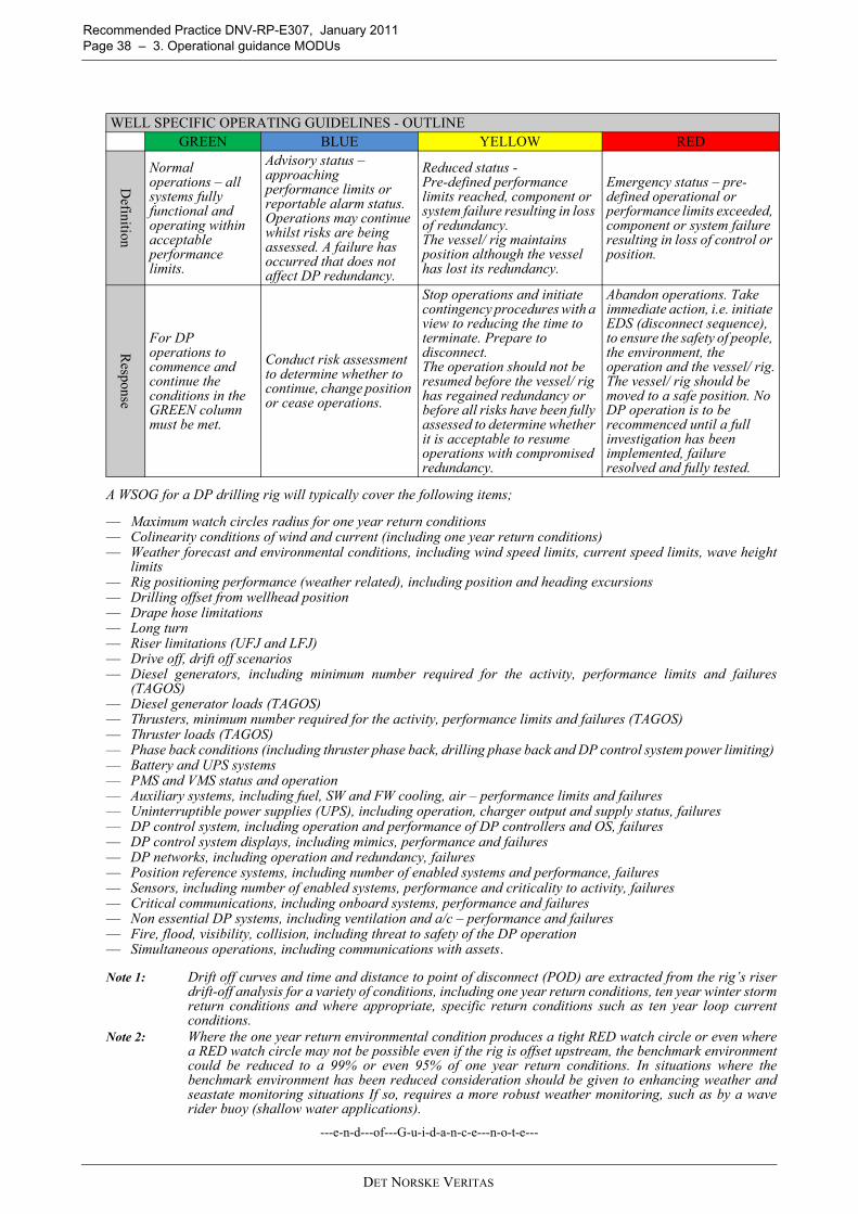
Recommended Practice DNV-RP-E307, January 2011 Page 38 – 3. Operational guidance MODUs
A WSOG for a DP drilling rig will typically cover the following items;
— Maximum watch circles radius for one year return conditions — Colinearity conditions of wind and current (including one year return conditions)— Weather forecast and environmental conditions, including wind speed limits, current speed limits, wave height
limits— Rig positioning performance (weather related), including position and heading excursions — Drilling offset from wellhead position — Drape hose limitations— Long turn — Riser limitations (UFJ and LFJ)— Drive off, drift off scenarios — Diesel generators, including minimum number required for the activity, performance limits and failures
(TAGOS)— Diesel generator loads (TAGOS)— Thrusters, minimum number required for the activity, performance limits and failures (TAGOS)— Thruster loads (TAGOS)— Phase back conditions (including thruster phase back, drilling phase back and DP control system power limiting) — Battery and UPS systems — PMS and VMS status and operation — Auxiliary systems, including fuel, SW and FW cooling, air – performance limits and failures— Uninterruptible power supplies (UPS), including operation, charger output and supply status, failures— DP control system, including operation and performance of DP controllers and OS, failures— DP control system displays, including mimics, performance and failures— DP networks, including operation and redundancy, failures— Position reference systems, including number of enabled systems and performance, failures— Sensors, including number of enabled systems, performance and criticality to activity, failures— Critical communications, including onboard systems, performance and failures — Non essential DP systems, including ventilation and a/c – performance and failures— Fire, flood, visibility, collision, including threat to safety of the DP operation — Simultaneous operations, including communications with assets.
Note 1: Drift off curves and time and distance to point of disconnect (POD) are extracted from the rig’s riserdrift-off analysis for a variety of conditions, including one year return conditions, ten year winter stormreturn conditions and where appropriate, specific return conditions such as ten year loop currentconditions.
Note 2: Where the one year return environmental condition produces a tight RED watch circle or even wherea RED watch circle may not be possible even if the rig is offset upstream, the benchmark environmentcould be reduced to a 99% or even 95% of one year return conditions. In situations where thebenchmark environment has been reduced consideration should be given to enhancing weather andseastate monitoring situations If so, requires a more robust weather monitoring, such as by a waverider buoy (shallow water applications).
---e-n-d---of---G-u-i-d-a-n-c-e---n-o-t-e---
WELL SPECIFIC OPERATING GUIDELINES - OUTLINEGREEN BLUE YELLOW RED
Definition
Normal operations – all systems fully functional and operating within acceptable performance limits.
Advisory status – approaching performance limits or reportable alarm status. Operations may continue whilst risks are being assessed. A failure has occurred that does not affect DP redundancy.
Reduced status - Pre-defined performance limits reached, component or system failure resulting in loss of redundancy. The vessel/ rig maintains position although the vessel has lost its redundancy.
Emergency status – pre-defined operational or performance limits exceeded, component or system failure resulting in loss of control or position.
Response
For DP operations to commence and continue the conditions in the GREEN column must be met.
Conduct risk assessment to determine whether to continue, change position or cease operations.
Stop operations and initiate contingency procedures with a view to reducing the time to terminate. Prepare to disconnect.The operation should not be resumed before the vessel/ rig has regained redundancy or before all risks have been fully assessed to determine whether it is acceptable to resume operations with compromised redundancy.
Abandon operations. Take immediate action, i.e. initiate EDS (disconnect sequence), to ensure the safety of people, the environment, the operation and the vessel/ rig.The vessel/ rig should be moved to a safe position. No DP operation is to be recommenced until a full investigation has been implemented, failure resolved and fully tested.
DET NORSKE VERITAS

Recommended Practice DNV-RP-E307, January 2011 3. Operational guidance MODUs – Page 39
3.12 CommunicationsThe vessel should be equipped with the appropriate primary and secondary equipment needed to communicatebetween all parties (stakeholders) whilst carrying out the intended task.Effective internal and external communications is a key tool to manage risk.Communications in this context include voice, visual (lights/ displays) and audible means (alarms). Means ofcommunication are not limited to the above but include integrated IT systems using wireless networktechnology that combine communications with other features, including AIS and DGNSS. Operational specific visual and voice communications should ensure that the pertinent information flowsbetween the key operating points as well as to and from assets and/ or other vessels that might be affected bythe operation being carried out. These operating points may be onboard the vessel as well as on other facilities involved with the activity.Communication protocols are to be set up to provide pertinent information regarding intent, current status ofplanned as well as unexpected events during the execution of the activity. Continuity of communications during foreseeable emergency situations should be taken into account. Communications should be taken into account when detailing the roles and responsibilities of key personnelduring the planning stages for the intended task, ensuring that a common working language and terminology isused at all times. Guidance on communications is provided in M103, M182 and M205.
Note: The importance of communication to be emphasized by incorporating into the WSOG.
Guidance note:There should be redundant voice communications systems to all key locations on board the DPO vessel. At least oneof the systems should be hands free. The DPO should have a view or CCTV coverage of all important operationalareas onboard as well as of important points of interest external to the vessel. Communications and alarm systems should be protected against power supply failure. Battery/ UPS back up powersupplies are recommended.Some modern communications and alarm systems rely solely on software activated alarms through the network. Thissole dependency is not recommended. Manual activation of alarms should never be overlooked in design or in operation.Communications and alarm systems for all DP related equipment and systems and other equipment and systems notdirectly related to DP, but which will have an effect on DP, should be located close to the DP control station. Thisshould include fire zone alarms systems. Simultaneous operations (SIMOPS) depend on effective communications between all vessels and units involved in theoperation. It is important that change of status between vessels and units engaged in SIMOPs is communicatedspeedily and reliably. It should be noted that developments in sensor and communications technologies are underwayto relay, among other things, change of vessel or unit SMO or WSOG status. With these systems any change of statusfrom GREEN to BLUE, YELLOW or RED will be instantaneously relayed to all vessels and units engaged in SIMOPs.These technologies are expected to deliver and aid in the management of complex SIMOPS.
---e-n-d---of---G-u-i-d-a-n-c-e---n-o-t-e---
3.13 DP Planned MaintenanceDP vessels should have a structured planned maintenance system that specifically addresses maintenance ofthe vessel’s DP system, equipment and support systems. Relevant guidance is given in IMCA M109.Planned maintenance should address all equipment that has an impact on the vessel’s station keepingcapabilities. This should include indirect components such as generator circuit breakers, bus tie breakers, etc.Maintenance should include regular cleaning, calibration, and testing of equipment as outlined inmanufacturer’s recommendations and industry guidelines.Records of planned and unplanned maintenance should be kept in an auditable format, either hard copy orappropriate electronic format. These records should include vendor service records as well as maintenanceperformed by vessel personnel. These records should be kept on board for the period specified by the owner/operator. A minimum number of required critical DP spares should be maintained on board. The critical spare inventoryshould be monitored via a formal inventory program that is closely linked to the planned maintenance system.This should assist in getting back to normal operating condition after equipment failure or DP incident.
Note: The client’s due diligence process is usually the main driver in the critical path to return to normaloperating condition. Typically, this also involves vendor support as well as the client’s DPconsultant.
Note: Maintenance on DP related equipment whilst conducting DP operations should be controlled bya documented permit to work system and should always take into consideration the potentialalteration of failure modes and increased criticality of failure consequences on DP capabilitiesand/ or redundancy.
DET NORSKE VERITAS
Recommended Practice DNV-RP-E307, January 2011 Page 40 – 3. Operational guidance MODUs
Note: System upgrades and changes (hardware and software) are typically subject to class approval. Inaddition, parts replaced during maintenance may require certification by class.
Guidance note:It should be recognised that DP MODUs may from time to time require that certain items of equipment aretemporarily taken out of service for the purposes of essential planned maintenance. Where thrusters and/ orgenerators are temporarily taken out of service this is likely to have an impact on the rig’s DP capability and its worstcase failure. In preparation for these occasions it is recommended that a thruster and generator operating strategy(TAGOS) is developed to take account of the impact on DP capability and/ or worst case failure. If the impact on DPcapability and/ or worst case failure is significant, it is suggested that additional DP capability plots correlated tothe TAGOS be provided on the vessel. It is recognised that deferring scheduled planned maintenance due to work activities increases the potential forfailures. Vessel operational teams are encouraged to incorporate planned maintenance as a guideword in HIRA’s(Hazard Identification and Risk Assessments).
Note: The potential for common mode failures increases where same vendor equipment of same type and ageare installed and in operation. (Example experienced - simultaneous failure of three wind sensors ofsimilar type and hours of service (“aging”) accompanied by mechanical stressing (gusts experiencedduring a hurricane event that was in proximity of the rig).
---e-n-d---of---G-u-i-d-a-n-c-e---n-o-t-e---
3.14 DP IncidentsDP vessels should be provided with and operate appropriate DP incident reporting, investigation and closingout procedures. This should be in accordance with vessel owner or operators’ and, if applicable, clients’processes. Documented records should be kept and be capable of auditing. Where SMO, TAM and WSOG are used as tools to manage DP operations a suggested approach is that, apartfrom the exceptions in the notes below, any reactive change of DP status from GREEN to YELLOW or REDshould be regarded as a DP incident, and should be reported, recorded and investigated.
Note: A change of status triggered by prearranged agreement between the Master, and senior onboarddecision makers, allowing the vessel to exceed environmental limits should not be regarded as aDP incident.
Note: An operator initiated change of status as a result of a conscious decision based on risk analysis of thecircumstances where the trigger points have not been reached should not be regarded as a DP incident.
It is recommended that reactive YELLOW and RED DP incidents are investigated as soon as practicable afterthe DP incident and, where relevant, trials are carried out as part of the investigation process. The purpose of the investigation and the trials should be:
— to assist in identifying the root causes of the incident— to verify and validate that measures to address the root cause are effective— to validate that effective measures have not introduced any additional potential to cause failures (both
hidden and apparent).
In the event of the occurrence of a DP incident relating to the vessel’s configuration as described in the DPFMEA and other documents, it is suggested that the FMEA provider is involved in the incident investigation.This will facilitate lessons learnt to be implemented into the DP FMEA and proving trials program. Owners/ operators of DP vessels are encouraged to share lessons learned from DP incidents with the wider DPcommunity. DP systems and equipment vendors are also encouraged to do likewise and to share informationon unexpected faults, features and failures that are identified in operation. IMCA’s station keeping incidentreporting scheme provides a suitable channel for disseminating relevant information throughout the DP sector.
Guidance note:The IMCA station keeping incident reporting scheme has been in place for many years and annual reports arepublished each year which summarise each reported incident as well as providing an overview of all the incidents forthe year. These annual reports are available to IMCA members and non-members alike. Owners/ operators arerecommended to make these reports available to key DP personnel onboard their vessels so that they can learn fromthe experience of others.The IMCA station keeping incident reporting scheme or other repositories of DP incidents needs the support of thewhole DP community to be an effective learning, sharing and risk mitigating tool. It is acknowledged that there couldbe a reluctance to participate in sharing of incidents for fear of unwanted disclosure of company identification as thesource of the DP incident. Industry bodies who provide repositories for incident reporting are encouraged to provideanonymity and positively communicate this to the DP community. Owners/ operators are encouraged to draw uponlearnings from incidents experienced and avoid recurrence. Vessel operational teams are encouraged to systematically evaluate potential for incidents on their own units basedon published analysed information. Where additional technical support is required to aid this systematic analysis itshould be sought.
---e-n-d---of---G-u-i-d-a-n-c-e---n-o-t-e---
DET NORSKE VERITAS

Recommended Practice DNV-RP-E307, January 2011 3. Operational guidance MODUs – Page 41
3.15 Reporting and Record KeepingOwners or operators of DP vessels should have an effective reporting and record keeping system. There should be a clear line of reporting DP related items onboard the DP vessel and between each departmentand this should involve key DP personnel. There should also be a clear line of reporting between the DP vesseland the company’s shoreside management. DP related records should be maintained onboard and, whereappropriate, at the company’s premises. The documents and records contained in Sec.3.2.2 should be accessible to key DP personnel and to otherinterested parties.DP vessels, on occasion, carry out activities which may be unique to project requirements. Records of theseactivities including pertinent information from Hazards and Risk Identification (HIRAs) should be made andkept onboard for future reference, both for training and familiarisation processes as well as for reference in caseof similar project requirements in the future.
Guidance note:The following records should be kept and made accessible to vessel crew and to other interested parties.
— DP FMEA & FMEA Proving Trials reports— Annual DP Trials— DP checklists for bridge and engine room— DP incident investigations & close out reports (see Note 1 below)— DP system faults, repairs, modifications and upgrades (see Note 2 below)— Vessel specific familiarisation and training for short service employees involved in DP operations and ongoing
training and development programs for experienced DP personnel— Operational logs & DP alarm print outs— DP data logging records— DP system equipment vendor reports — DP Footprint Plots— Vessel overview documents, SMO and WSOGs, TAGOS.
DP vessels, on occasion, carry out activities which may be unique to project requirements. Effective record keeping of such activities has the following benefits,
— assists in identifying best practices — demonstrates the vessel’s performance— facilitates knowledge capture and transfer — assists in identifying or justifying equipment improvements.
Guidance on reporting and record keeping is provided in M109, M163
Note 1: Owners/ operators should recognise the benefits that electronic DP data logging systems offer whencarrying out DP incident investigations and establishing root cause.
Note 2: Documentation relating to modifications and upgrades should be kept and available for reference. Thiswill include risk analysis of the interfaces and documentation and records of all commissioning andtesting.
---e-n-d---of---G-u-i-d-a-n-c-e---n-o-t-e---
3.16 CompetenceDefinition: Competence is the acquisition of knowledge, skills and abilities at a level of expertise sufficient
to be able to perform in an appropriate work setting.DP vessel owners/ operators should operate a structured competence assurance program that is applied to allkey DP personnel with special focus on ensuring vessel and task specific competence. Guidance is provided in M103, M117 (IMO738).Vessel specific competency should, as a minimum, be demonstrated in the following areas:
— Operational modes— DP FMEA familiarization— DP Operations Manual familiarization— Project/ activity requirements— Contingency plans, modes and drills.
Guidance note:Key DP personnel include masters, DPOs, engineers, electricians, electronic technicians and anyone involved in thesafe position keeping capabilities of the vessel and includes those involved in the deployment of PRSs. Owners/operators are encouraged to develop their own competency verification processes for all key DP personnel. IMCA M117 provides the DP sector with detailed guidance on the training and experience of key DP personnel. M117has been adopted by the IMO and issued as IMO MSC/Circ 738 (1996). A reference to M117 is also made in the
DET NORSKE VERITAS

Recommended Practice DNV-RP-E307, January 2011 Page 42 – 3. Operational guidance MODUs
MODU Code. M117 provides guidance on formal training courses for DPOs and other key DP personnel, including watchkeepingmarine engineers and electronic maintenance staff. M117 recognises the formal training and certification scheme forDPOs administered by the Nautical Institute. The Nautical Institute scheme is universally recognised as the industrystandard for formal training and certification of DPOs. The Nautical Institute DPO certificate scheme is made up of a combination of formal DP induction and DP simulator(advanced) and onboard supervised watchkeeping experience. There are two levels of DPO certification;
— Unlimited DPO certificate (minimum requirement for DPO on DP Class 2 or DP Class 3 vessels)— Limited DPO certificate (minimum requirement for DPO for DP Class 1 vessels).
DPO certification is only one part of the competency assurance process for DPOs. Such certification is not to beconstrued as validation of competency. Owners/ operators are recommended to refer to further formal training programs described in M117, comprising thefollowing main features for electrical and engineering officers, where appropriate;
— High voltage (HV) training— Power management system (PMS) training— Fire and gas detection and emergency shutdowns (ESD) training— DP control system manufacturer’s maintenance training.
M117 also provides guidance on structured onboard familiarisation programs for key DP personnel, covering thesteps to take to achieve, maintain and enhance competency in DP operations. Owners/ operators may consider implementing the IMCA Competence Assurance & Assessment scheme (IMCA C002Rev 1, 2003) which provides detailed programs for achieving and assessing the competency of key DP personnel,including vessel masters, DPOs, chief engineers and engineers in charge of a watch.
Note: Owners/ operators should also be aware of and recognise the benefits of formal training andcompetency programs that are currently offered by equipment suppliers, vendors and other bodies thatare in excess of established industry standards, such as the Kongsberg initiative in POWERSIMtraining where DPOs are given training, familiarisation and exposure to a variety of power generationrelated faults and conditions that are known to have occurred on DP diesel electric power generationsystems.
Note: Customised training programs have been developed by industry in response to clients requests.Owners/ operators are encouraged to seek information and selectively adopt appropriate programs fortheir training needs.
---e-n-d---of---G-u-i-d-a-n-c-e---n-o-t-e---
3.17 ManningVessels must comply with the statutory requirements for safe manning. Additionally, for DP operations,manning should be in accordance with the following:DP Bridge Crew
EngineersThere should be sufficient licensed engineers on board for all expected operations. At least one licensed engineer should be available at all times, should be on watch during critical activities andshould have at least 6 months experience on similar equipment and operations. The engineer should be fully cognisant of DP operations, familiar with the vessel’s DP FMEA document and
Operation Minimum Bridge Crew per shift Minimum ExperienceWhen undertaking critical activities in proximity to surface or sub surface structuresSee Note 1 below
2 unlimited DPOs on the bridge capable of operating the vessel both in DP and manual control. See Note 2 below.
Unlimited DPO with a minimum of 3 years experience in DP operations, at least 6 months of which should have been on the subject or sister vessel. Experience level should be documented and auditable.See Note 3 below
Note 1: Critical activities are those activities where the consequences of equipment failure or loss of position are greater than under normal operating circumstances. For example, critical activities on a DP dive support vessel would include those occasions where the Time to Terminate is long, such as when the diver is inside a welding habitat or where the diver’s worksite is inside the conductor tubes at a production facility.
Note 2: The Master should not be considered as one of the required unlimited DPOs for meeting the manning requirements since operating as such would negative affect the situational awareness required from his side.
Note 3: It is recognized that in practice, given the near term market conditions owners/ operators will be challenged to meet the recommended level of experience for DPOs. Owners/ operators should recognize the associated risk from inexperienced personnel and have plans in place to address them while striving to reach the recommended experience levels.
DET NORSKE VERITAS

Recommended Practice DNV-RP-E307, January 2011 3. Operational guidance MODUs – Page 43
the effects of failures of equipment relating to the position keeping of the vessel.In DP 2 or 3 operations, the engineer should be familiar with the general philosophy of redundancy as it relatesto split mechanical, electrical and ancillary systems.Electrician/ Electrical EngineerIf required on board, an electrician should have appropriate high voltage training/ certification, if applicable tothe vessel. As with vessel engineers, the electrician/ electrical engineer should have at least 6 monthsexperience on similar equipment and operations.The electrician should likewise be fully cognisant of DP operations, familiar with the vessel’s DP FMEAdocument and the effects of failures of equipment relating to the position keeping of the vessel.Notes: Where the minimum experience requirements cannot be met a risk based approach should be taken todetermine the suitability of personnel and any additional support requirements for intended operations.For low risk operations guidance is provided in IMCA M182. If used, the guidance provided within thisdocument should be validated against the risks.
3.18 Intervention – Role of the DPO and EngineerIntroductionThe notes in this section consider the role of the DPO and watchkeeping engineers, specifically addressingoperator intervention in terms of the complexities of the regulatory background (operator interventionspecifically addressed in Class rules) as well as operational practicalities.
Note: The overriding role of the DPO in emergency situations is to stabilise the situation and to takepositive action to prevent escalation.
GeneralRules and guidelines on levels of operator intervention in response to a failure in a DP Class 2 or DP Class 3vessel have changed over the years and different classification societies have chosen to place different levelsof emphasis and different interpretations on these rules. The practical effect of this is that vessels of differentages and different class society can vary significantly in terms of the amount of operator intervention expected,allowed or required. Even in the case of DP Class 1 vessels, levels of redundancy and automation areinfluenced by differences in the main rules for the classification of ships. Examples of the rules and guidelines that have influenced the design of redundancy concepts are given below:-
IMO MSC 645 Section 3.1.4 states under the heading of Functional Requirements,
General: “Redundant components and systems should be immediately available and with such capacity thatthe DP-operation can be continued for such a period that the work in progress can be terminatedsafely. The transfer to redundant components or systems should be automatic as far as possibleand operator intervention should be kept to a minimum. The transfer should be smooth and withinacceptable limitations of the operation.”
DNV rules for the classification of Ships Pt.6 Ch.7 Sec.2 states:
Redundancy: “The DP-system shall be designed with redundancy. A position keeping ability shall bemaintained without disruption upon any single failure. Full stop of thrusters and subsequentstart-up of available thrusters is not considered an acceptable disruption. Guidance note: Component and system redundancy, in technical design and physicalarrangement, should in principle be immediately available with the capacity required for theDP-system to safely terminate the work in progress. The transfer to components or systemsdesigned and arranged to provide redundancy, should be automatic and operator interventionshould be avoided.”“Redundancy shall be based upon running machinery. Automatic or manual interventionarranged to improve the position keeping ability after a failure will be accepted. Automaticstart of equipment may be accepted as contributing to redundancy only if their reliability andsimplicity of operation is satisfactory so that they can be brought into operation before positionand heading keeping performance is degraded. Guidance note: The redundancy requirements will not be considered as complied with if basedupon start or restart of generators and/ or thrusters.”
The distinction between ‘improving station keeping capability after a failure’ and ‘contributing to redundancy’should be noted. The latter is intended to mean that the contribution of this equipment or feature can beconsidered when defining the vessel’s post WCF DP capability. The former cannot be considered whendefining this capability thus DP Class 2 and DP Class 3 vessels should not operate in conditions where theywould depend on this equipment to maintain position. However, the feature can be used to improve capability.
DET NORSKE VERITAS

Recommended Practice DNV-RP-E307, January 2011 Page 44 – 3. Operational guidance MODUs
Faults requiring operator intervention
— The following list comprises known faults and features in DP systems that have been known to requireoperator intervention to prevent escalation of the failure effect or loss of position. Prudent watchkeepingpractices will detect the listed events that require operator (DPO/ engineer) intervention,
— A faulty thruster may respond poorly to DP commands giving rise to a speed/ torque or azimuth predictionerror. The DPO should assess the performance of the thruster and shut it down using the emergency stopif necessary.
— Failure of a thruster to full thrust or uncontrolled rotation will require the DPO to shut the thruster downusing the emergency stop. The process of identifying the faulty thruster may be made more difficult by thefact that all thrusters may be operating at high thrust to counteract the effect of the faulty one. Predictionerrors may indicate which thruster is faulty.
— A DP operator station may fail. The DPO must take control at another operator station. Note that positionand heading should be maintained by the DP controller during this time.
— Seawater cooling systems operated from a single sea chest may block giving rise to low seawater pressurealarms requiring the engineers to transfer to the other sea chest.
— Some vessels have no automation for starting redundant pumps and engineers must monitor the conditionof the plant and intervene following an unexpected stop.
— A heat exchanger in a common freshwater cooling system may become fouled requiring the engineers tochange over to another cooler. This condition may be indicated by high freshwater temperature alarms.
— In some diesel electric designs, failures of fuel control systems or generator excitation systems candestabilise the entire plant if the vessel is operated with a common power system (busties closed). In suchcircumstances the engineers may open the bustie in an attempt to isolate the fault to one side or the other.A load sharing imbalance alarm may assist in identifying the onset of the fault. Note that in somecircumstances the fault may escalate at a rate which precludes effective operator intervention and blackoutmay result.
— A distribution system supplying a DP UPS may fail. The ‘on-batteries’ alarm will indicate to the DPO thatcertain important DP control system consumers may be lost. The DPO or ET can review the UPSdistribution list against sensors, reference systems and operator stations in use to determine whether anyconfiguration changes should be made, for example selecting the other DP controller or OS before theonline controller or OS fails.
— On some DP vessels with a single stern tunnel thruster and two main propellers which depend on therudders to provide redundant athwartships thrust it may be necessary to transfer the tunnel thruster to theother power distribution system and restart it in the event that the distribution system supplying one mainprop and the stern tunnel thruster fails.
— On a DP Class 3 vessel, loss of the main DP station will require the DPO to take control at the backup DPstation.
— On a DP Class 2 vessel loss of both DP control systems will require the DPO to take manual control of thevessel at the independent joystick or manual control levers.
— On vessels with two wind sensors a difference alarm may require the DPO to make an assessment of whichwind sensor to use. In the case that one of the wind sensors has failed to ‘high wind speed’ it may benecessary to rapidly deselect the faulty wind sensor before it initiates a drive off depending on the type ofDP control system.
— On vessels with only two gyro compasses a difference alarm may require the DPO to make an assessmentof which gyro to use. A faulty gyro may cause a rapid change of heading if not deselected promptly.
— On vessels with two MRUs a difference alarm may require the DPO to make an assessment of which MRUto use.
— DP control systems employ a range of protective functions designed to reject an errant position referencesystem. Class rules require that three references are in use for DP Class 2 & 3 vessels and two of the threeshould be based on different principles of measurement. This provides a large degree of protection againsta drive off related to a position calculation error but such incidents do occur and DPOs can be expectedto determine which reference systems are responsible and deselect them.
— On vessels with a common fuel supply system, which can be found even on some DP Class 2 vessels, it maybe necessary to change over a fuel filter or isolate a leak to prevent all generators being affected.
— On some vessels with transferable thrusters it may be necessary for the engineers to manually change overauxiliary services for the thruster even if the main supply changes automatically. This changeover, ifrequired, is to prevent the unexpected consequences of failure.
— DPOs should be aware of the thruster and/ or power configuration that is used to activate the ConsequenceAnalysis alarm. It should not be assumed that it is Worst Case Failure. Where it is established that it is notWCF then steps should be taken to ensure that WCF is used as the trigger for a Consequence Analysisalarm.
— DPOs should use the weather radar or standard radar, set up for weather, to augment their watch keepingpractices to aid in proactive measures to be taken as necessary (eg Squall line observed on radar- startadditional generators/change heading as necessary).This is especially relevant during night time and wheninclement weather is being forecast and//or being experienced.
DET NORSKE VERITAS

Recommended Practice DNV-RP-E307, January 2011 3. Operational guidance MODUs – Page 45
Measures to reduce the incidence of faults requiring operator intervention:The most effective way to avoid the necessity for operators and engineers to intervene in faults is to design theredundancy concept in such a way that the need for operator intervention is minimised or preferablyeliminated.In general terms, this will often mean adding additional equipment, greater levels of redundancy, automationand increased system segregation to minimise the impact of any failure. Features such as a third wind sensoror a third DP controller allow voting or other protective functions to be used. However, there may be some aspects of DP system design where operator intervention is preferred to any otherform of response. For example, it may not be desirable to automatically transfer control location in responseto a fault. It may be better for the operator to decide where control transfers to by taking control at that station. There is also a risk that poorly designed protective functions will reduce the reliability and availability ofessential equipment such as thrusters and generators. This risk should be considered when applying protectivefunctions to deal with very low probability failure modes.Carefully considering power plant and control system configuration can also reduce the need for operatorintervention. DP Class 2 and 3 vessels should always operate in a redundant/ fault tolerant configuration.Where operator intervention in response to faults is unavoidable then it is extremely important that there areclear and unambiguous alarms and indications to alert the operators to the onset of the fault. It is also of vitalimportance that the required responses to the fault are documented in well-written procedures and practicedso that all DPOs and engineers are familiar with them and can take action in a confident manner.
DET NORSKE VERITAS

Recommended Practice DNV-RP-E307, January 2011 Page 46 – 3. Operational guidance MODUs
3.19
DP
Foot
prin
t Plo
ts -
Wor
ked
Exa
mpl
es
Figu
re 3
-1W
orke
d E
xam
ple
1
DET NORSKE VERITAS

Recommended Practice DNV-RP-E307, January 20113. Operational guidance MODUs – Page 47
Figu
re 3
-2W
orke
d E
xam
ple
2
DET NORSKE VERITAS
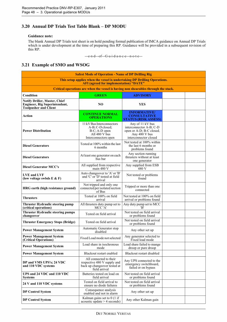
Recommended Practice DNV-RP-E307, January 2011 Page 48 – 3. Operational guidance MODUs
3.20 Annual DP Trials Test Table Blank – DP MODU
Guidance note:The blank Annual DP Trials test sheet is on hold pending formal publication of IMCA guidance on Annual DP Trialswhich is under development at the time of preparing this RP. Guidance will be provided in a subsequent revision ofthis RP.
---e-n-d---of---G-u-i-d-a-n-c-e---n-o-t-e---
3.21 Example of SMO and WSOG
Safest Mode of Operation - Name of DP Drilling RigThis setup applies when the vessel is undertaking DP Drilling Operations.
AFI (agreed for implementation) “DATE”Critical operations are when the vessel is having non shearables through the stack.
Condition GREEN ADVISORY
Notify Driller, Master, Chief Engineer, Rig Superintendant, Toolpusher and Client
NO YES
Action CONTINUE NORMAL OPERATIONS
INFORMATIVE/CONSULTATIVE
STATUS (RISK ASSESS)
Power Distribution
11 kV Bus Interconnectors A-B; C-D closed; B-C; A-D open All 480 V bus
Interconnectors open
Any of 11 kV bus interconnector A-B; C-D open or A-D; B-C closed.
Any 480 V bus interconnector closed
Diesel Generators Tested at 100% within the last 6 months
Not tested at 100% within the last 6 months or
problems found
Diesel Generators At least one generator on each bus bar
Any section running thrusters without at least
one generator
Diesel Generator MCC's All supplied from respective main 480 V
Any supplied from ESB 480 V
LVE and LVF (low voltage swbds E & F)
Auto changeover to 'A' or 'B' and 'C' or 'D' tested at field
arrivalNot tested or problems
found
HRG earth (high resistance ground)Not tripped and only one
connected per isolated section of Bus
Tripped or more than one connected
Thrusters Tested at 100% on field arrival
Not tested at 100% on field arrival or problems found
Thruster Hydraulic steering pump (critical operations)
All thrusters duty pump set to MCC 'A'
Any duty pump set to MCC 'B'
Thruster Hydraulic steering pumps changeover Tested on field arrival Not tested on field arrival
or problems found
Thruster Emergency Stops (Bridge) Tested on field arrival Not tested on field arrival or problems found
Power Management System Automatic Generator stop disabled Any other set up
Power Management System (Critical Operations) Fixed Load mode not selected Any generator selected to
Fixed load mode
Power Management System Load share in isochronous mode
Load share failed to mange droop or pure droop
Power Management System Blackout restart enabled Blackout restart disabled
DP and VMS UPS's; 24 VDC and 110 VDC systems
All connected to their respective 480 V supply and back up changeover tested at
field arrival
Any UPS connected to the emergency switchboard,
failed or on bypass
UPS and 24 VDC and 110 VDC Systems
Batteries tested on load on field arrival
Not tested on field arrival or problems found
24 V and 110 VDC systems Tested on field arrival to ensure no diode failures
Not tested on field arrival or problems found
DP Control System Consequence analysis enabled and not in alarm Any other set up
DP Control System Kalman gains set to 0 (1 if acoustic update > 4 seconds) Any other Kalman gain
DET NORSKE VERITAS

Recommended Practice DNV-RP-E307, January 2011 3. Operational guidance MODUs – Page 49
Back Up DP Transfer of control tested at field arrival
Transfer not tested or known problems
DP Reference SystemMedian Check set up and
enabled, with agreed references
One of the agreed references unavailable
Position References AvailableFour references selected and enabled (2 DGPS and 2 LBL). DGPS 1 or 2 and DGPS 3 and
LBL 1 and LBL 2
Less than three references available, or both DGPS 1
and 2 selected
Position References Available Both Acoustics (LBL) dedicated to DP control
Acoustics also being used actively by survey or others
DGPS Systems on different
differential systems and elevation masks
Any other set up
AcousticsFrequencies in use planned with other DP vessels in the
areaNot planned
AcousticsIf both Acoustics in use, interfaced to alternative
MARHSBoth Acoustics using same
MAHRS
Placement of targets for OSV's
Redundant targets placed at optimum locations suitable for diverse relative position reference systems on board OSV's (CyScan, Fanbeam,
RadaScan, Radius)
Single targets, or obscured or poorly sited. Only one
type installed.
Fuel SystemsPurifier gravity discs matched
Strict anti-contamination procedures in practice
Any other set up
Main Engine SW cooling Each main pump fed from its own sea chest.
Any main pump fed from the adjacent sea chest.
Main Engine SW cooling Port and stbd system isolated from each other
Port and stbd systems common.
Electric' SW CoolingValves VELXXX and
VELYYY closed. Valves VELZZZ and VELAAA open
Any other set up
Electric' SW Cooling Changeover of Duty/Standby pump tested at field arrival
Changeover of Duty/Standby pump not tested on
field arrival or problems found
Electric' FW CoolingStandby start function of
cooling pumps tested at field arrival.
Standby start function of cooling pumps not tested at
field arrival or problems found.
Start air4 compressors available. 2
receivers isolated port/stbd cross connection isolated
less than 4 compressors available or all receivers on
line or cross connection open
ESD Life boat station ESD's disarmed
Life boat station ESD's armed
Air Conditioning to all DP critical areas
All AHU's running & changeovers tested recently
for cooling pumps and compressor units
Any AHU off or changeover not recently
tested or any HVAC alarm
Engine Room Manning ECR Manned by qualified Engineer
ECR not Manned or engineer not qualified
DET NORSKE VERITAS

Recommended Practice DNV-RP-E307, January 2011 Page 50 – 3. Operational guidance MODUs
Well Specific Operating Guidelines - Name of DP Drilling Rig
Condition GREEN ADVISORY YELLOW REDNotify Driller, Master, Chief Engineer, Rig Superintendant, Toolpusher and Client
NO YES YES YES
ActionCONTINUE NORMAL
OPERATIONS
INFORMATIVE/CONSULTATIVE
STATUS (RISK ASSESS)
HALT OPERATIONS AND
INITIATE CONTINGENCY PROCEDURES
(Prepare for disconnect)
INITIATE EDS (disconnect sequence)
Water Depth XXXX m Emergency Disconnect Time XXs
The Emergency Disconnect time is to be established from field trials. If the time is measured by a surface test, 10 seconds is to be added for conservatism.
The Red watch circle below is to be established from calculated drift off curves at 1 year environment, defined Point of Disconnect (POD) and the measured EDS (disconnect sequence) time. If environmental conditions are in excess of the 1 year environment and a blackout occurs, a Red status is to be issued immediately.From FMEA proving trials, blackout restart time was established at around 1 minute 30 seconds from blackout to recovery of all thrusters1 Year Winter storm is 41 knots of wind, Hs 16 feet, Surface current is 0.7 knots
POD 4.1%, Time to POD 142 s
10 Year Winter storm is 50.5 knots of wind Hs21.7 ft, Surface current is 0.86 knots
10 year Loop current is 19 knots of wind, Hs 6 ft; current is 2.2 knots
POD 10%, Time to reach POD 352 s
For Total EDS (disconnect sequence) and unlatch time XX s
Red watch circle at 39 m
Based on mud weight aa ppg; top tension cccc kips
Maximum Watch Circles Radius (From Well Head position) <1 year condition (<=Wind 41 knots, current 0.7 knots, Hs 16 ft)
39 m
Maximum Watch Circles Radius (From Well Head position)- > 41 knots, current 0.7 knots Hs 16 ft and colinear
Immediately if blackout occurs
Colinearity (1 year winter storm)
If wind < 30 knots and current is less than 0.5 knots and colinearity >
than 15 deg
If Wind is >30 knots and current is >0.5
knots and colinearity within 15 deg
If wind approaching 41 knots and current is
approaching 0.7 knots and colinear
Colinearity (loop current)If wind < 15 knots and current is less than 1.5 knots and colinearity >
than 15 deg
If Wind is >15 knots and current is >1.5
knots and colinearity within 15 deg
If wind approaching 19 knots and current is approaching 2 knots
and colinear
Weather Forecast Within Operating limits Approaching operating limits
Exceeding operational limits
DRIVE OFF or All systems operating correctly
Difference in vessel position between
Survey, Navigation and DP
Immediately when recognized by DPO
Unable to control Drive Off
DRIFT OFF
Drilling offset from well head position
Position directly over wellhead Any offset from ZAP =/>12.m
Heading excursion No Heading Alarms or warning
If heading warning limit reached (>3 degrees)
If heading Alarm limit reached (>5 degrees) or
Heading instability with frequent alarms
Vessel Footprint/Weather related excursion (From Set point)
No position alarms or warning
If warning position limits reach (>3 m)
If Alarm position reached (>5 m) or
Position instability with frequent alarms
Drape Hose Heading Limitation
> -200 ° < +200 ° +/-200 to 240° > -240 °
< +240 ° To be established at
Field TrialsLong Turn Being considered Under execution
DET NORSKE VERITAS

Recommended Practice DNV-RP-E307, January 2011 3. Operational guidance MODUs – Page 51
Riser Limitation (UFJ) 0 - 2° >2 ° >4 °
Riser Limitation (LFJ) 0 - 2° >2 ° >4 °
'Power Trains'/Thrusters in use
At least two diagonally opposite pairs of
thrusters running and selected to DP (1 thruster
in each corner)
Any selected thruster in alarm
Less than two diagonally opposite
thruster pairs running and selected to DP
Thruster loading (thrust)all <values given in
generator configurations and limits document
any approaching values given in generator configurations and limits document
All > values given in generator
configurations and limits document
Any change in thrusters/propulsion in or out of use Advisory
Diesel Generator LoadsAll < values given in
generator configurations and limits document
Any generator approaching values given in generator configurations and limits document
All available generators > values given in
generator configurations and limits document
Any change in generators in or out of use Advisory
Thruster phase back, drilling phase back or DP control system power limiting
No Alarm Approaching operating limits
Alarms and or phasing back or limiting -
DP UPS's and 24 VDC Systems
Main and back up supply available no UPS in by pass. No UPS alarms
Any UPS in bypass or in alarm
Main supply cannot be reinstated or total UPS
failure
DP Control System Power mimic information correct Any wrong information
Critical information wrong or DP is in
power limit
DP Control System Triplex Any 1 CC Controller failed
Any 2 CC Controllers failed
DP Network Dual Any alarms or poor performance 1 network lost Complete loss of
networks
VMS/PMS Controllers Dual Any alarms or poor performance 1 Controller failed
Position References Available
Four references selected and enabled (2 DGPS
and 2 LBL). DGPS 1 or 2 and DGPS 3 and LBL 1
and LBL 2
Three references available, or both
DGPS 1 and 2 selected
Only two references available or One
system (no redundancy in system - i.e. DGPS
only or Acoustics only)
Motion sensors (MRU/VRU) into DP 3 or 2 MAHR/MRU 1 MAHR/MRU or
difference alarmloss of all MAHR/
MRU
Heading Sensors (Gyro) 3 Gyros 2 Gyros 1 remaining Gyro
Wind Sensors 3 or 2 wind sensors 1 wind sensor No sensor and Gusty conditions
Loss or problem with any essential Communications (DP / ECR / Driller / ROV)
Redundant Communications One system remaining No comms -
Engine Room(s) Ventilation Full ventilation Any reduced ventilationComplete loss of
ventilation resulting in power reduction
Air Conditioning to Critical Equipment Full Air Conditioning
Any reduced Air Conditioning or frequent alarms
(initiated from ECR)
Reduced Air Conditioning affecting
critical equipment
Starting Air 4 compressors available Any compressor in alarm or not available Any loss of start air
Fire - E/R or elsewhere No fire, no fire alarms Any fire alarm Fire Confirmed -
Flood No bilge alarms active, no flooding Multiple bilge alarms Flood Confirmed -
CollisionNo collision imminent /
minimum approach >500 m
Minimum approach will be < 500 m If collision possible Collision Imminent
DET NORSKE VERITAS

Recommended Practice DNV-RP-E307, January 2011 Page 52 – 3. Operational guidance MODUs
SIMOPS - Well Specific Operating Guidelines - Name of DP Drilling Rig
Condition GREEN ADVISORY YELLOW RED
Notify Other vessels in the field, Driller, Master, Chief Engineer, Rig Manager, Toolpusher and Client
NO YES YES YES
ActionCONTINUE NORMAL
OPERATIONS
INFORMATIVE/CONSULTATIVE
STATUS (RISK ASSESS)
HALT OPERATIONS AND
INITIATE CONTINGENCY PROCEDURES
INITIATE EDS (disconnect sequence)
Change from Green DP Status of any other vessel in the field Green Advisory Advisory Advisory
Comms/interaction with other vessels
Vessels operating normally with no known problems
Comms problem or possible position
conflictNo comms or definite
position conflict
Notes:
1. This document shall be followed as closely as possible during DP Operations.
2. Escape Route to be established. Signed:
On behalf of Owner/Operator
Printed name
On behalf of Client
Printed name
DET NORSKE VERITAS

Recommended Practice DNV-RP-E307, January 2011 4. Operations guidance Project/Construction Vessels – Page
4. Operations guidance Project/Construction Vessels
4.1 IntroductionThis chapter contains DP operational guidance, specific for Project and Construction Vessels. For overviewand full appreciation, this information is completed with the general management information as already wasgiven in chapter 2. For distinction, the general information is printed in regular text, and the specific operationalguidance is in italics and/or grouped under Guidance notes.
4.2 DP Operational Documentation
4.2.1 GeneralIt is recommended that DP vessel owners/ operators should maintain the documentation listed in the tablebelow and should develop and implement associated processes for the purposes of:
— ensuring the safe and effective management of the vessel in DP— ensuring the technical suitability of the vessel for each DP activity it is required to carry out— determining the configuration for the safest mode of operation and the task appropriate mode— understanding the vessel’s station keeping capabilities following the worst case failure— ensuring compliance with appropriate standards and guidelines— providing training and familiarization material to vessel crews.
4.2.2 Recommended Documentation Current versions of the documents in the list below should be kept on board and, in addition, where feasible, atthe shore based centers of technical management. Documents that have been superseded should be clearlymarked and kept separate from current versions. Documents may be in electronic or, hard copy format or, both.
No. Document Management Guidance Operational Guidance1 DP System FMEA
or FMECA To be kept up to date, incorporating all modifications and additions since original study, if not in the document itself, then by other traceable means. All records to be kept on board.
Modifications and additions should be covered by a MOC process that triggers updating the FMEA.
2 DP FMEA Proving Trials
To be conducted to prove initial DP FMEA and at other times to prove modifications and additions to the DP system. DP FMEA Proving Trials should be repeated every five years. Findings and recommendations to be addressed in accordance with their criticality. All records to be kept on board.
Modifications and additions that should be proven by testing include all those that have directly effect or, potential to affect the performance or redundancy of the DP system. This will include protective, detection and monitoring functions.
3 Annual DP Trials To be conducted annually. Findings and recommendations to be addressed in accordance with their criticality. Previous trials reports and associated close out documentation to be kept on board.
The tests in the Annual DP Trials should be designed to prove system redundancy, as defined in the DP FMEA, system and equipment performance and functionality, to validate repairs and preventive maintenance, to test the operation of protection and detection devices and responses so as to demonstrate that the vessel’s DP system remains fit for purpose.
4 DP Capability Plots
Hard copy DP Capability Plots relevant to the vessel’s areas of operations to be readily accessible to DPOs at the DP control location.
Capability plots to be validated/ recalculated, as required, to ensure that they are suitable for the environmental conditions where the DP operations are to take place, in particular in respect of current speeds. This requirement to validate/ recalculate applies also in cases where DP vessel performance is affected by operational constraints imposed by the activity, such as in the case of a pipelay vessel with horizontal loads.
5 DP Footprints Hard copy DP Footprint Plots to be taken by DPOs. See Note 1 at end of table.
DP Footprint Plots should be taken regularly in various power/ thruster combinations, including fully intact and worst case failure and also in various environmental conditions.
6 Service reports concerning the DP system
Complete history of service reports to be filed and kept on board
There should be a process where the open items are highlighted, tracked and closed out.
DET NORSKE VERITAS

Recommended Practice DNV-RP-E307, January 2011 Page 54 – 4. Operations guidance Project/Construction Vessels
7 Details of all DP related modifications and additions
Records of all DP related modifications and additions to be kept on board complete with interface and testing information. See Note 2 at end of table.
A structured FMEA and Proving Trials approach should be used to integrate modifications and additions into the existing DP system and its associated equipment. New and modified software should be subjected to a thorough validation process, especially to avoid the acceptance of erroneous values. Known instances as examples pipe tensioner software that accepted a sudden increase of pipe tension from 100 t to 300 t (erroneous input), software for thruster control that increased the command to the thruster to match the faulty feedback.It is not enough to focus on the functionality of modifications and additions. It is equally important to fully understand the functional design spec and the dependencies and consequences of fault or failure.
8 Vessel audit reports and DP audits and inspection reports.
Complete history of all audit reports, DP audits and inspection reports, including findings and close outs to be kept on board
There should be a process where the open items are highlighted, tracked and closed out.
9 DP Operations Manual
Vessel Specific DP Operations Manual 1), to be readily accessible at the DP control location and used by the DPOs as a reference for conducting DP operations.
It is recommended that owners/ operators develop a standardised table of contents for vessel specific DP Operations Manuals in their fleet. Modifications and amendments to the DP Operations Manual should be subject to MOC processes, including changes to vessel specific checklists.
10 DP Incident Reports
Records of all DP station keeping and other DP related incidents to be kept on board, including investigation records and close outs.
All DP incidents should be investigated to an extent that reflects the potential consequences of the incident.
11 DP Mobilization/ DP Field Arrival/ Trials Procedures (Bridge and Engine Room)
Records of DP Mobilization Trials and DP Field Arrival Checklists to be kept on board for the period set by the owner/ operator and, where relating to a DP incident permanently stored in retrievable archives.
DP Trials and Checklists should be vessel specific and be developed from detailed information contained in the DP FMEA. They should confirm vessel performance, particularly following worst case failure, and that the vessel’s DP system is set up properly and provides the required level of redundancy.
12 DP Location and Watchkeeping checklists(Bridge and Engine Room)
Records of all DP Location and Watchkeeping Checklists to be kept on board for the period set by the owner/ operator and, where relating to a DP incident, permanently stored in retrievable archives.
As above
13 DP related drills and emergency response drills
Records of DP related drills and emergency response drills to be kept on board in retrievable archives.
DP drills can be developed from fault and single point failure scenarios addressed in the vessel’s DP FMEA. The drills should also cover extreme events that are outside the scope of the DP FMEA.The outcomes from these drills should be used in the development of DP emergency response procedures and used as training material for DP personnel. These records may be used in a cycle of continuous improvement.
14 DP fault log Records of all faults related to the DP system to be kept on board permanently in retrievable archives.
DP faults should be recorded as soon as possible after they are discovered and action/ investigation taken appropriate to the potential consequences of the fault on the vessel’s station keeping ability.
No. Document Management Guidance Operational Guidance
DET NORSKE VERITAS

Recommended Practice DNV-RP-E307, January 2011 4. Operations guidance Project/Construction Vessels – Page
Note 1: It is acknowledged that DP Footprint Plots may be less relevant for DP MODUs than for other DPvessel types.
Note 2: Owners/ operators should keep adequate records and documentation relating to modifications andadditions that could have an effect on the DP system, especially interfaces between equipmentfrom different vendors. This is as relevant for equipment whose primary function lies outside theDP system, such as an Emergency Shutdown Systems (ESD), pipe tensioner systems and firemonitor systems as it is for DP equipment, such as propulsion, position references and sensors.All modifications and additions should be subjected to FMEA type analysis and undergo ProvingTrials type testing. In addition, modifications and additions are typically subject to class approvaland inspection.
4.3 DP ClassIt is recommended that DP vessels with at least the following DP equipment class notations are used for thefollowing activities. Regulations, contractual specifications and/ or harsh environmental or other localconditions may require a higher class.
15 DP Data Logging Where the vessel has DP data logging facilities electronic records should be kept on board for the period set by the owner/ operator and, where relating to a DP incident, permanently stored in retrievable archives.
DP data loggers perform an important function in helping to determine root causes of faults or failures. It is recommended that DP data logging function is included as part of the DP system design spec, DP data loggers should be commissioned and operational before DP system Customer Acceptance Trials (CAT) are carried out. The DP data logger should be incorporated in the SMO and running at all times when in DP. If not, this should trigger an Advisory condition, i.e. BLUE.There should be specific procedures for the operation and analysis of output from the DP data logger. This should include clear instructions on how and where the records are kept. Retention of data logging data should not be limited by time.
16 DP alarm printer readouts
Hard copy records of the DP alarm printer readout to be kept on board for the period set by the owner/ operator and, where relating to a DP incident, permanently stored in retrievable archives.
Owners/ operators frequently require DP alarm printer readouts to be kept for the duration of each project and then destroyed, unless relating to a DP incident or contractual dispute.
17 DP familiarisation and competency records
All records relating to vessel specific DP familiarisation and competency for DPOs, engineers and electricians to be kept on board permanently in retrievable archives.
Owners/ operators should implement an in-house DP competency assurance process for key DP personnel which is structured, systematic and progressive. It should be noted that DPO certification is only one element in the competency assurance process. Owners/ operators are recommended to make use of facilities and training programmes available to the DP sector, such as the Powersim program for advanced DPO training of power plant fault conditions, where DPOs are given detailed instruction and training in identifying and responding to power system faults. Examples include DPO intervention averting an underfrequency induced blackout on closed bus system by the DPO taking control of thrusters and biasing to increase load.
18 Résumés and vessel specific work records of all key DP personnel
Résumés of all key DP personnel, copies of certification and qualifications, records of DP watchkeeping hours to be maintained on board. Original DPO certificates and DP Log Books to be held by the DPOs onboard the vessel.
1) The vessel specific DP Operations Manual is additional to the DP control system manufacturer’s Operator Manual
No. Document Management Guidance Operational Guidance
DET NORSKE VERITAS

Recommended Practice DNV-RP-E307, January 2011 Page 56 – 4. Operations guidance Project/Construction Vessels
Note 1: The vessel’s DP system should normally be set up and operated to deliver the intent of the DPclass notation. However, on occasion and after a proper assessment of the risks, the vessel may beset up in accordance with the requirements of the Task Appropriate Mode.
Note 2: For operations close to another vessel or installation the equipment class should be 3 or equivalent.Class 2 may be accepted based on considerations of procedures, equipment and consequenceanalysis.
Note 3: It is noted that there have been standards developed outside the IMO DP equipment classsystematics where an identical (or higher) level of redundancy has been realized based on adifferent philosophy and system approach.
Guidance note:A detailed risk analysis will be required if the vessel is to operate in a task appropriate mode (TAM) that providesless redundancy than that provided by the vessel’s DP equipment class notation. The detailed risk analysis should consider the consequences of loss of position relevant to the activity.
---e-n-d---of---G-u-i-d-a-n-c-e---n-o-t-e---
4.4 DP FMEAThe DP vessel’s DP FMEA is the most important technical document in the list of required documents. Therequirement for a DP FMEA has its origins in IMO MSC/Circ 645 (1994) “Guidelines for Vessels withDynamic Positioning Systems”. These benchmarking guidelines provide the foundation for all subsequent DPrules, regulations and guidance issued by Class and other industry bodies, such as IMCA.The IMO Guidelines require all DP vessels to be subjected to survey and testing in accordance with IMO’sspecified guidelines. This includes initial and periodic complete survey and testing of all systems and componentsrequired to keep position after single failures associated with the vessel’s assigned DP equipment class. The periodic component in the IMO Guidelines requires the complete survey and testing to be repeated everyfive years to ensure full compliance with applicable parts of the guidelines. In addition compliance with IMO Guidelines requires survey and testing after defects are discovered andcorrected and, after a DP related accident and, whenever significant repairs or alterations are carried out, so asto demonstrate full compliance with applicable parts of the guidelines. The IMO Guidelines do not make clear distinction between vessels of different DP equipment class.This IMO requirement has been interpreted by the DP community such that the survey requirement is met bya DP FMEA (or FMECA 1)) and the testing requirement by DP FMEA Proving Trials. 1) Unless expressly stated in this Guidance document a FMECA is interchangeable with an FMEA.
Accordingly, all DP vessels of DP Class 2 or 3 are required to have a Class approved and stamped DP FMEAand DP FMEA Proving Trials. In addition to complying with the IMO Guidelines and the relevant DP rules of the vessel’s Classification
Application on DPMinimum Recommended
DP Equipment Class(See Note 1 below)
Remarks
Drilling 2
Diving 2 Pipelay 2
Umbilical Lay 2 Lifting 2
Accommodation 2 Shuttle Offtake 2
ROV Support (Open Water) 1
ROV Support (Close Proximity - Surface/ Subsea) 2
Floating Production 2 Seismic and Survey vessels (Open
water- outside 500 m zone) ** ** Class in accordance with contractual requirements
Well Stim 2* * Vessels of lesser Class may be used with the appropriate structured risk identification and mitigation measures in place.
Logistics Operations 2*
DET NORSKE VERITAS

Recommended Practice DNV-RP-E307, January 2011 4. Operations guidance Project/Construction Vessels – Page
Society the DP FMEA should achieve the standards of detail and analysis contained in the following industryguidance;
— IMCA M166 “Guidance on Failure Modes and Effects Analysis”— IMCA M178 “FMEA Management Guide”— IMCA M04/04 2004 “Methods of Establishing the Safety and Reliability of DP Systems”
Note: FMEAs are a requirement to obtain DP Class 2 and 3 notation. Whilst not stipulated as a classrequirement for DP 1 vessels owners/ operators are encouraged to subject their DP 1 vesselsto the DP FMEA process.
Note: Particular attention should be paid in the DP FMEA to the interfaces between the DP system andother systems that have the potential to affect the DP system, such as where the vessel is fittedwith an Emergency Shut Down (ESD) system, pipe tensioner system or fire monitor system.
Key DP personnel, including the vessel Master, DPOs, Engineers and Electricians should have a detailedknowledge of the DP FMEA and should use the information provided to be fully informed about thecapabilities and limitations of the vessel’s DP system. The results from a DP FMEA, in particular issues related to the vessel’s worst case failure and significant singlepoint failures, should be used in the formulation of operational, emergency response and planning decisions.
Guidance note:These Guidance Notes on DP FMEAs are intentionally brief. They give a concise overview of the underpinningphilosophy, analytical processes and the technical content of a DP FMEA. Relevant IMCA guidance, referred to inthis section, should be consulted to gain a more detailed understanding. A DP FMEA should encompass the following:
— identify worst case failure design intent (WCFDI) and worse case failure (WCF),— identify the equipment or subsystem, mode of operation and the equipment,— Identify all potential failure modes and their causes,— identify the significant single point failures,— identify potential hidden failures, — identify potential configuration errors,— evaluate the effects on the system of each failure mode,— Identify measures for eliminating or reducing the risks associated with each failure mode,— identify trials and testing necessary to prove the conclusions,— be updated after any major modifications and proving trials have been conducted,— be subject to review and update as necessary, once every five years. The review should take account of new
equipment and hardware/ software updates, new developments in analysis and new knowledge acquired in theintervening period,
— take account of action items from DP FMEA Proving Trials, Annual DP Trials, audits and incidents which havebeen or, are in the process of being, closed out,
— take account of non DP systems/ auxiliary/ external systems that have interfaces with, and potential impact onDP and station keeping. These systems should be subjected to the FMEA and Proving Trials approach forsoftware, hardware and interfaces thus ensuring the integrity of the DP system and proper integration with DP,
— take account of common mode failures that are otherwise liable to be overlooked, such as the effects ofhydrocarbon gas on engine control and safety systems, which can cause diesel engines to accelerate out ofcontrol resulting in catastrophic mechanical failure and potential for black out,
— be presented as a narrative analysis of DP related systems and subsystems covering the above points (i.e.redundancy concept, hidden failures, configuration errors, etc.) and be supported by sketches and drawings,
— for DP Class 3 vessels, should consider the effects of fire and flood, not only from a compartment analysisperspective but also, where significant, at the subsystem level, e.g. the effects of fire and flood on ESD controllines and push buttons.
Note: Where the redundancy concept relies on inter-switching mechanisms, the reliability and effectivenessof these mechanisms should be proven and fully documented in the DP FMEA.
Note: The DP FMEA should contain an analysis of the DP control system I/Os to verify that it is consistentwith the redundancy concept and should be proved at DP FMEA Proving Trials.
Note: The DP FMEA should address the ESD function (if fitted), in particular the various issues relating tothe status of post activation battery power supplies (UPS). Appropriate guidance is given in section 6.6of IMCA M196, “Guidance on the Design, Selection, Installation and Use of UPS onboard Vessels”.
Note: The findings from a DP FMEA and Proving Trials should be categorised into A, B or C. Categoriesshould be clearly defined. Appropriate definitions are as follows;A: For immediate attentionThe failure effect exceeds worst case failure design intent or is non compliant with specified rules andguidelines, e.g. Class rules. Improvement is required for class compliance.B: For attention when reasonably convenientThe failure effects equal worst case failure design intent but there is an opportunity to reduce the failureeffect as reasonable cost. A cost benefit analysis is recommended.C: For considerationComments and observations related to good practice.
DET NORSKE VERITAS

Recommended Practice DNV-RP-E307, January 2011 Page 58 – 4. Operations guidance Project/Construction Vessels
A FMECA is an extension of an FMEA that adds a risk assessment of each failure mode to determine its criticality.Criticality is derived from an assessment of the probability that a particular failure will occur combined with theseverity of the failure if it does occur.A DP FMECA should encompass all of the listed points in DP FMEA above and, in addition, include the following steps;
— determine the severity of each failure mode,— determine the probability of occurrence of each failure mode (using qualitative or reliable MTBF data),— determine and rank the criticality of the identified failure modes from highest to lowest,— determine a strategy for dealing with the ranked criticalities so that remedial measures are directed
appropriately in accordance with the criticality ranking,
The Criticality Analysis should be presented in tabulated form making use of risk matrices that comply withrecognised international standards such as those given in IMCA M166 or IEC 60812.
Note: The closing out of action items should be well documented and auditable.
The following IMCA Guidelines address the above considerations in various levels of detail; M166, M178, M04/04and Annex.A DP FMEA should be referred to at the following times;
— conducting task based DP operational risk assessments, where key personnel involved should have detailedknowledge of the DP FMEA,
— determining the DP vessel’s Safest Mode of Operation (SMO), e.g. where the unavailability of equipment mayreduce the vessel’s DP station keeping ability,
— determining the DP vessel’s Activity Specific Operating Guidelines (ASOG), e.g. where equipment performanceapproaches or exceeds predetermined limits,
— determining the vessel’s Task Appropriate Mode, when applicable and warranted by the specific DP operations,— developing planned maintenance schedules, taking account of the impact of taking systems or equipment out of service,— developing the vessel’s DP Operations and Emergency Response manuals and procedures,— developing DP trials programs and checklists, ensuring that the single point failures identified in the DP FMEA
are covered in the trials and checklists.
Note to Owners: In the case of newbuilds, if DP FMEAs are within the shipyard’s scope of supply, owners arerecommended to ensure that there are contractually binding agreements for the FMEA to meetspecifications set out in IMCA Guidelines, M166. M178, M04/04 and Annex and preferably becarried out by an independent third party DP FMEA practitioner.
Cautionary Note: DP FMEAs that are solely focused on attaining class notation and class approval may notalways meet guidance standards stipulated in those IMCA Guidelines.
---e-n-d---of---G-u-i-d-a-n-c-e---n-o-t-e---
4.5 DP Capability PlotsDP Capability Plots should be calculated for the vessel. Guidance is provided on DP Capability Plots in IMCAM140 Rev 1, “Specification for DP Capability Plots”.These theoretical plots are calculated from detailed information of the vessel’s hull and superstructure form andavailable thruster power. The calculations should use environmental data (seastate, wind and current)appropriate to the area in which the DP vessel is to operate. These plots should show the limiting wind speed 360 degree envelopes for the scenarios below, where eachpoint on the envelope represents the wind speed at which it is calculated that the vessel will be unable tomaintain position in DP.
— DP Capability Plots should include the following scenarios at current speeds of 0, 1 and 2 knots, or at othercurrent speeds that are representative of the location in which the DP vessel is to operate:
— Fully intact power generation and thrusters.— Loss of most effective thruster(s).— Following the worst case failure.
Note: The DP Capability Plots should be provided in a format that is intuitive to the user on board(e.g. Polar Plot).
Guidance note:DP Capability Plots that do not cover Worst Case Failure are incomplete. DP Capability Plots that do not take intoaccount thruster interaction, (thruster-thruster, thruster-hull), thruster degradation and thruster barred zones areincomplete.Owners/ operators should note that it is important to provide a detailed scope of work to whoever is to generate theDP Capability Plots for the vessel. Experience has shown that those who generate the DP Capability Plots, such asthe DP system manufacturers, may not include the Worst Case Failure, unless specifically instructed to do so. This isparticularly relevant where the DP Capability Plots are included in the shipyard’s scope of supply for newbuilds. DP Capability Plots may have to be recalculated from time to time during the lifetime of a DP vessel. For example,the installation of new equipment, such as a crane or an accommodation module on deck will alter the vessel’s outline,
DET NORSKE VERITAS
Recommended Practice DNV-RP-E307, January 2011 4. Operations guidance Project/Construction Vessels – Page
which, in turn, will alter the wind effect on the vessel. In these circumstances the DP Capability Plots should be re-calculated to take account of the changes. DP Capability Plots may also have to be recalculated for thruster configurations where, due to unforeseen faults orfailures or, due to essential maintenance requirements, one or more thrusters are no longer available. Where notalready covered by existing calculations the revised DP Capability Plots should cover the following cases for the newthruster condition; i.e. the new fully intact condition, the new loss of most effective thruster(s) and the new worst casefailure condition. DP Capability Plots should be readily available to the DPOs at the DP control console. DPOs should consult DP Capability Plots as a matter of course whilst the vessel is conducting DP operations. DPOs should be fully familiar with the limits given in the DP Capability Plots for the fully intact thrusterconfiguration, for loss of most effective thruster and for worst case failure. DPOs should be careful when estimating the current force acting on the vessel and relating it to the DP CapabilityPlots. DPOs should be aware that the current force generated by the DP control system is the residual external forceacting on the vessel that cannot be measured. When wind speeds are low an attendant vessel, if available, could beused to estimate current by going into drift mode. DP Capability Plots should be used by DPOs and other key DP personnel as a reference in the planning phases whendetermining the vessel’s environmental operational limits for the ASOG. Where the DP Capability Plots show anundue level of heading limitations this may restrict the vessel’s operating range. This is not uncommon on vessels,such as DP tankers, that have good fore and aft thrust capability but limited thwartship capability. It should be remembered that DP Capability Plots are theoretical calculations and that, wherever possible,opportunities should be taken to validate the DP Capability Plots by taking DP Footprint Plots. See Sec.4.6.
---e-n-d---of---G-u-i-d-a-n-c-e---n-o-t-e---
4.6 DP Footprint PlotsDP Footprint Plots should also be produced on board. DP Footprint Plots are not theoretical. They are actualmeasurements of the vessel’s DP station keeping performance in the actual environmental conditions andthruster configuration at the time the plot was taken. DP Footprint Plots should be taken whenever opportunitiesarise, such as during standby periods, weather downtime or on arrival at the field. Plots should be taken for thethruster configurations used in the DP Capability Plots, i.e. fully intact, loss of most effective thruster(s) andafter worst case failure.Some DP systems have a software application that produces DP Footprint Plots electronically. DPOs can alsoproduce DP Footprint Plots by manual methods using a plotting sheet.DP Footprint Plots serve two main purposes.
— They provide a scatter plot of vessel positions at regular intervals around the required set position (thisshows accuracy of station keeping)
— They also provide comparison points on the limiting wind speed envelope given in the theoretical DPCapability Plots (this shows wind speeds at which it was seen that the vessel was unable to maintainposition, thus validating or contradicting the theoretical DP Capability Plots for the various thrusterconfigurations.)
DP Footprint Plots serve other purposes, including learning and familiarisation opportunities for DPOs and inproviding snapshots of vessel station keeping behaviour for specific locations and activities. Theoretical DP Capability Plots and DP Footprint Plots combine together to enhance knowledge andunderstanding of the vessel’s DP station keeping ability.
Note: DP Footprint Plots originated in harsh weather regions, such as in the North Sea. The plots areused to gain a better understanding of the vessel’s actual station keeping performance andlimitations in intact and, in various degraded thruster configurations, including worst case failure,whilst the vessel is being subjected to real environmental forces.
It is acknowledged that DP Footprint Plots may be of less relevance to DP MODUs.Guidance note:Manual DP Footprint Plots are generated in the following manner.
1) Use a proforma plotting sheet, comprising a 360 degree polar plotting diagram, vessel outline with thrustersindicated and space for vessel specific position reference systems and environmental data. Refer to plotting sheetsin Sec.3.19.
2) The vessel should be in auto DP. Record wind, waves and current on the plotting sheet, drawing appropriate vectors.3) Record thruster configuration on the plotting sheet.4) Record the rate of turn and speed of moves. It is suggested that the following values are applied, 10 deg/min and
0.3 m/sec, respectively, to prevent misleading results. 5) Observe position excursions from the intended position by the most appropriate means, plotting the vessel’s
position regularly, e.g. every 30 seconds.
DET NORSKE VERITAS

Recommended Practice DNV-RP-E307, January 2011 Page 60 – 4. Operations guidance Project/Construction Vessels
Sec.3.19 contains two worked examples. Both worked examples are for the same DP semi submersible drilling rig 1)
and in the same environmental conditions. Wind was 45 to 50 knots from 225 degrees with a corresponding waveheight of 6 m. Current was 1 coincident at 1 knot.
Example 1: shows a DP Footprint Plot for the rig’s fully intact condition with all eight thrusters operational.The plot shows that the vessel was able to maintain position within +/- 2 meters with the windand sea on the port quarter.
Example 2: shows a DP Footprint Plot for the rig’s worst case failure condition with four thrustersoperational. The plot shows that the rig was unable to maintain position with the wind and seaon the port quarter.
Example 3: The known circumstances at the time of taking the DP Footprint Plot, of wind, wave height andthruster configuration, in which the rig failed to maintain position, can be compared against theenvironmental envelope plotted on the theoretical DP Capability Plot for worst case failure.They should be similar in that the DP Capability Plot should also show that vessel will be unableto maintain position in conditions where a 45 to 50 knots wind is on the port quarter. If there isa significant difference between the two, particularly if the DP Capability Plot shows that thevessel can maintain position in the given condition, then it may be necessary to pull in thelimiting wind envelope on the DP Capability Plot to the upper wind speed determined by the DPFootprint Plot for these conditions.
Cautionary Note: The DP Footprint Plot positions will contain systematic position reference errors.
---e-n-d---of---G-u-i-d-a-n-c-e---n-o-t-e---
1) The example DP Footprint Plots for a DP semi submersible drilling rig are equally applicable to many project/ construction vessels.
4.7 Position Reference Systems and SensorsThe DP vessel should be equipped with suitable position reference and sensors in accordance with the vessel’sDP class notation and operational requirements. Position reference systems should be selected with dueconsideration to operational requirements, both with regard to restrictions caused by the manner of deploymentand expected performance in working situations.Position reference systems comprise absolute and relative systems. An absolute system gives vesselgeographical position. A relative system gives vessel position in relation to a non-fixed reference. A relativesystem can be used as an absolute system if installed on a point that is a fixed geographical position. And, anacoustic absolute system can be used as a relative system if attached to a non-fixed asset. The following are the most common position reference systems in use.
Note 1: Class rules give minimum requirements for the number of position references. Where operationaluptime is one of the key success factors the benefit gained by consciously exceeding the minimumrequirements are to be evaluated. Other benefits of exceeding minimum requirements includegreater redundancy and improved station keeping performance.
Note 2: It could be debated that Taut Wire and Acoustic Position reference systems are relative positionreference systems. For purposes of this document, absolute indicates that this position referencesensor is independent of another fixed or floating offshore structure.
Caution: Additional position reference systems should be based on different principles. It is generally notrecommended to use multiple (>2) satellite based systems in conjunction with other positionreference systems as this may result in skewed weighting in favor of multiple satellite systems.
Caution: DP reference systems sensitive to interferences from the vessels radars, radios etc. should not beused during critical operations such as sub-sea operations.
Guidance note:The reference system may be subject to contract specifications/ oil major requirements. Notwithstanding these,operational guidance on position reference systems and sensors is given in the table on the next page.
---e-n-d---of---G-u-i-d-a-n-c-e---n-o-t-e---
Absolute DGNSS (DGPS and GLONASS)Acoustic (USBL, SBL, LBL)Taut wire (See Note 2)
Relative ArtemisLaser (e.g. Fanbeam, Cyscan)Radar (e.g. RADius, RadaScan)DARPS
DET NORSKE VERITAS

Recommended Practice DNV-RP-E307, January 20114. Operations guidance Project/Construction Vessels – Page 61
Re
com
men
ded
Abso
lute
Pos
ition
Ref
eren
ce S
yste
ms
Reco
mm
ende
d Re
lativ
e Pos
ition
Ref
eren
ces S
yste
ms i
f in
clos
e pro
xim
ity to
an
offs
hore
stru
ctur
e Se
nsor
sA
pplic
atio
n on
D
PG
PSD
GN
SS
(DG
PS +
G
LON
ASS
)(S
ee N
ote
2 be
low
)
SBL
(See
N
ote
1 be
low
)
USB
L/
SSB
L(S
ee
Not
e 1
belo
w)
LBL
(See
N
ote
1 be
low
)
Taut
W
ire
(See
N
ote 1
2 be
low
)
Min
N
umbe
r (S
ee N
ote
3 be
low
)
Arte
mis
Lase
rR
adar
Gan
gway
D
AR
PSM
in F
ixed
pl
atfo
rm(S
ee
Not
es 4
, 5
& 6
be
low
*)
TLP/
SPA
R/e
tc
< m
in
mov
emen
t(S
ee N
otes
4, 5
&
6 b
elow
*)
TLP/
SPA
R/e
tc
> m
in
mov
emen
t(S
ee N
otes
4, 5
&
6 b
elow
*)
Gyr
os,
VR
Us a
ndW
ind
Sens
ors
(See
Not
e7
belo
w)
Dril
ling
If in
deep
op
en
wat
er
Red
unda
nt -
one
dual
fr
eque
ncy
<700
m<7
00 m
>700
m<3
50 m
3Y
YY
NN
3 m
ixed
ab
s & re
l3
mix
ed a
bs &
re
l3
rela
tive
only
3
Div
ing
NY
<700
m<7
00 m
>700
m<3
50 m
3Y
YY
NN
3 m
ixed
ab
s & re
l3
mix
ed a
bs &
re
l3
rela
tive
only
3
Pipe
lay
NY
NN
NN
3Y
YY
NN
3 m
ixed
ab
s & re
l3
mix
ed a
bs &
re
l3
rela
tive
only
3
Um
bilic
al L
ayN
YN
NN
N3
YY
YN
N3
mix
ed
abs &
rel
3 m
ixed
abs
&
rel
3 re
lativ
e on
ly3
Ris
er P
ull i
nN
Y<7
00 m
<700
m>7
00 m
<350
m3
YY
YN
N3
mix
ed
abs &
rel
3 m
ixed
abs
&
rel
3 re
lativ
e on
ly3
Lifti
ngN
Y<7
00 m
<700
m>7
00 m
<350
m3
YY
YN
N3
mix
ed
abs &
rel
3 m
ixed
abs
&
rel
3 re
lativ
e on
ly3
Acc
omm
odat
ion
NY
<700
m<7
00 m
>700
m<3
50 m
3Y
YY
YN
3 m
ixed
ab
s & re
l3
mix
ed a
bs &
re
l3
rela
tive
only
3
Shut
tle O
ffta
keN
YN
NN
N3
YY
YN
Y3
mix
ed
abs &
rel
3 m
ixed
abs
&
rel
3 re
lativ
e on
ly3
RO
V S
uppo
rtN
Y<7
00 m
<700
m>7
00 m
<350
m2
NN
NN
N*
**
See
Not
e 8
belo
w2
Floa
ting
Prod
uctio
n U
nit
NY
<700
m<7
00 m
>700
m<3
50 m
3N
NN
NN
NA
NA
NA
3
Wel
l Stim
N u
nles
s op
en
wat
er
Y<7
00 m
<700
m>7
00 m
<350
m2
YY
YY
Y2
**
2
OSV
Sna
tch
Lifts
NY
<700
m<7
00 m
>700
m<3
50 m
2Y
YY
NN
12
mix
ed a
bs
and
rel
22
OSV
HA
ZMA
T Tr
ansf
er n
o qu
ick
disc
onne
ct
NY
<700
m<7
00 m
>700
m<3
50 m
3Y
YY
YN
23
mix
ed a
bs &
re
l3
rela
tive
only
3
OSV
HA
ZMA
T Tr
ansf
er w
ith
quic
k di
scon
nect
NY
<700
m<7
00 m
>700
m<3
50 m
2Y
YY
YN
2*
*3
OSV
with
shaf
t ge
ns a
nd si
ngle
st
ern
thru
ster
NY
<700
m<7
00 m
>700
m<3
50 m
2Y
YY
YY
3*
*3
Win
d Tu
rbin
e in
stal
latio
nN
YN
AN
AN
AN
A2
NN
NN
NN
AN
AN
A2
Stan
dby
Ves
sels
YY
<700
m<7
00 m
>700
m<m
1N
NN
NN
NA
NA
NA
1 or
<
DET NORSKE VERITAS

Recommended Practice DNV-RP-E307, January 2011 Page 62 – 4. Operations guidance Project/Construction Vessels
Note 1: (Acoustics) – The acoustic LUSBL system is not included in the above table since it is acombination of USBL and LBL in one system, where the USBL is typically used to calibrate theLBL system. The abbreviations, USBL and SSBL, are referred to in the above table. Although the abbreviationsdiffer they both refer to the same acoustic application although supplied by different vendors.It is recommended that, wherever possible, multiple acoustic systems are completely separatedand independent in all respects. For instance, this would require the use of separate andindependent hull transceivers.Owners/ operators should consider the advantages of acoustic positioning systems that have aninertial navigation input, such as the Kongsberg HAIN (Hydro Acoustic Inertial Navigation)system or Sonardyne’s AAINS (Acoustically Aided Inertial Navigation System) both of which can,:- overcome the update rate limitations of speed of sound in water,- overcome the limitations on satellite based position reference systems brought upon by poorsatellite geometry.
Note 2: (Satellite Systems) – Satellite based systems that use a combination of signals from DGPS andGLONASS satellites provide enhanced redundancy over systems that use only a single satellitesource. It is recommended that, wherever possible, multiple satellite based systems are completelyseparated and independent in all respects. For instance, this would require the use of differentmasts for the satellite antennae, separate cable routeing, different vendors and software. Wherethere is diversity of vendors and software it is recommended that the acceptance/ rejection logicis verified against the DP system manufacturer’s specifications. There have been incidents in thepast where diversity of vendors and software has resulted in loss of position due to the acceptanceof erroneous values within the software.Care should be taken at all times when using satellite based systems close to platforms. Guidanceis given in IMCA M141, “Guidelines on the Use of DGPS as a Position Reference in DP ControlSystems”, which highlights potential problems when within 150 m of a platform, such as themasking of GPS signals, masking of differential signals, radio interference and multipath. GoodDGPS close to structures should be considered as a bonus. In these locations DGPS should notbe considered as the primary position reference system.Where multiple DGPS systems are being used, consideration should be given to set each systemwith a different elevation mask. This is so that any jump in position that may occur when a satellitecomes into view will hit one DGPS before the next and will give the DPO some time to take action. Special care should be taken where there is a potential for multi path of DARPS signals, such aswith construction vessels at non fixed assets. Experience has shown that this may result incomputer freeze and the need for re-boot. Construction vessels intending to use DARPS as aposition reference should assess consequences of freeze in a risk analysis and evaluate thepotential to use other effective relative position reference sensors.Owners/ operators should consider the advantages of hybrid GNSS/ IMU positioning systems,such as the Kongsberg Seatex 4D system, where an inertial input is applied to the satellite basedsystem’s position calculation. This enhancement can fill the “holes” in positioning information inextraordinary and difficult conditions that otherwise might invalidate the satellite basedpositioning information, such as during times of scintillation and satellite ageing.
Note 3: (Absolute Systems) - Where multiple absolute systems are used it is recommended that they arebased on two different principles. Only where it is impractical to use systems based on differentprinciples may all be of the same type. This is of particular significance where DGPS is concernedwhere the satellite constellation provides a source for a common mode failure.
Note 4: (DP at non fixed Assets, e.g. FPSOs/ TLPs/ Spars) – When carrying out DP activities in closeproximity to or in conjunction with floating facilities it is strongly recommended that redundantrelative position reference systems are used. In these situations a mix of absolute and relativeposition reference systems for station keeping is to be used only after validating that movement ofthe floating structure, if any, does not impact station keeping. The DPOs must be extremelyvigilant when using a mix of absolute and relative position references and must be fully aware ofthe potential danger of diverging positioning information from both types of system.The minimum movement referred to in the table above refers to the actual measured movement offloating facility, e.g. FPSO/TLP/SPAR. To measure this movement the DP vessel should use anabsolute position reference system, such as DGPS, as the sole source for positioning informationand use the relative positioning system, such as RADius, RADASCAN or Fanbeam, sited on thefloating facility to measure the fluctuations in its movement. It should also be noted that there are non fixed offshore facilities, such as TLPs and Spars wherean acoustic system, although normally considered as an absolute system, can be used as a relativesystem. This can be accomplished by installing the transponder/ beacon onto the submerged partof the TLP or Spar at an appropriate depth. Some TLPs and Spars are fitted with suitable subseabrackets or cradles for transponders/ beacons.
DET NORSKE VERITAS

Recommended Practice DNV-RP-E307, January 2011 4. Operations guidance Project/Construction Vessels – Page
Note 5: (Absolute and Relative Systems) - When using DGPS/ GLONASS in a mix of absolute and relativeposition reference systems, in particular where there are two satellite based systems in a mix ofthree, users should bear in mind the possibility of the offshore structure blocking the satellitesignals and the consequences for station keeping.
Note 6: Wherever practical and feasible it is recommended that redundancy requirements are met bydiversity of suppliers, e.g. satellite based position reference systems from different manufacturersand differential signals from different sources. This applies equally to sensors such as gyrocompasses, VRUs and wind sensors.
Note 7: (Sensors) - Given the impact on heading/ position keeping it is recommended that vessels with anequivalent DP 2 class notation are provided with three gyro compasses, irrespective of therequirements of the applicable Classification Society DP rules. It should be noted that someClassification Societies, including ABS and DNV already require three gyro compasses for a DPclass 2 notation. Gyro compasses are normally fitted with a correction facility which inputs the vessel’s latitudeand speed. The effects of incorrect latitude or, more importantly, speed could result in asignificant error in output heading. It is therefore important to ensure that the latitude and speedcorrections are applied. Some systems use automatic input from GPS for these corrections. Thisis not recommended since there are a number of system errors that can result in undesiredheading changes. It is therefore recommended to use manual input of latitude and speed. It is becoming more prevalent for gangway access systems to use sensors such as VRUs to provideheave/ motion compensation. Where these sensors are interfaced to DP it is essential that anFMEA systems engineering approach is used at the design stage and in validation commissioningand that particular attention is paid to interfacing and testing. Wind sensors are known to have suffered common mode failures, such as icing in higher latitudes,lightning, heavy rain and birds. All types of wind sensor are vulnerable, including ultrasonictypes. Where ultrasonic type wind sensors are fitted, the consequences for station keeping ofcommon mode failures, that affect these ultrasonic sensors, may be prevented by fittingmechanical wind sensors.DP vessels are frequently fitted with sensor systems, other than heading, motion and wind, whichhave a potential to affect the DP system and station keeping should there be an erroneous orinvalid input from them. These include draft sensors and pipelay tension sensors, where anerroneous or invalid input could result in extreme values and distortion of external forces andresult in large position excursion (drive off) from the desired set point position. There should bemeans of preventing erroneous values from being accepted by DP. An often practiced procedurewhich should prevent the above problems is to input these values manually and not to rely on theautomatic input function, if fitted. There should also be means of ensuring that erroneous valuesare prevented from being input manually.
Note 8: Where it is anticipated that due to operational requirements the DP vessel will require to bepositioned in close proximity to the non fixed facility and where the potential for shadowing ofDGPS exists, then redundancy in relative position reference sensors should be considered.
Note 9: Where, as is normal, multiple position references are in use by DP, the DPOs should monitor theweightings closely so as to ensure that no one system or set of systems is ‘hogging” the weighting.DPOs should recognise the potential dangers of using multiple satellite based systems (>2) in thesuite of position reference systems and that this could result in skewed ‘weighting” in favor ofsatellite systems at the expense of other position references. It is recommended that no more thantwo satellite based position reference systems be used to provide position solution as inputs intoDP.
Note 10: New or retrofitted position references are sometimes interfaced into DP as another positionreference because the DP control system has not been designed to accept them. Examples of thisare pseudo Artemis or pseudo acoustics. This practice is not recommended unless accompaniedby a detailed risk analysis and the residual risk, if any, is deemed acceptable.
Note 11: The practice of connecting survey and DP is not recommended. Where it is unavoidable, isolationbetween the systems is to be provided. DPOs should have ultimate control over the input. Allnecessary precautions should be taken to ensure that the vessel’s station keeping is not affectedand should be addressed in the FMEA.
Note 12: (Taut wires) – Care should be exercised when lowering or repositioning taut wire weights thatdivers and ROVs are alerted and are a safe distance from the seabed position. Taut wire weightsshould also be placed clear of pipelines, manifolds or other subsea assets. These subsea assetsshould be positively identified prior to positioning taut wire weights, e.g. by the ROV. Care shouldalso be taken that the taut wires are not fouled by other subsea lines or obstructions. It is possible for thruster wash to interact with a taut wire, acting as a strong current and causingposition instability. The thruster wash could be from own vessel or from another vessel close by.DPOs should be aware of the potential for this to occur. DPOs should be alert to the potential for taut wire weights to “skip” along the seabed and provide
DET NORSKE VERITAS

Recommended Practice DNV-RP-E307, January 2011 Page 64 – 4. Operations guidance Project/Construction Vessels
inaccurate positioning information. This can be avoided by ensuring that the tension control isproperly calibrated and operating within specified parameters and that the angle of wireinclination is kept as near to vertical as is possible and should not normally exceed 10 degrees.DPOs should also be aware of the potential for taut wire systems to become a “perfect” reference.This can have different causes, including the taut wire touching the side of own vessel or,otherwise being restricted in its movement, or by a faulty gimbal sensor. Most DP systems willdetect this fault. DPOs should ensure that the warning and alarm limits are properly set andoperational. The wires in use in modern taut wire systems are generally 5 mm or 6 mm in diameter. Weightsare in the region of 400 kg to 500 kg. Taut wires are quite highly stressed for marine wire ropesand are liable to breakage, particularly at points of weakness, such as continuous wear at the spoton the main sheave, continuous wear at any guide blocks and kinks or damage caused by poorspooling or where the wire is attached to the weight. The potential for wire breakage is reducedby regular inspection of the taut wire system and by cropping the taut wire on a regular basis. Taut wire systems are known to suffer inaccuracies at water depths over 350 m, especially in highcurrent areas. Also at water depths under 350 m severe inaccuracies may occur. This should betaken into consideration when planning DP operations.
Note 13: It is important that software, parameters and values used by position reference systems arecompatible with the software and acceptance criteria used by the DP control system and that thisis verified by analysis and testing.Attention is drawn to IMO MSC/Circ 645 where three MRU/VRUs are stipulated when vesselpositioning is fully dependent on correct MRU/VRU signals.
4.8 Recommended DP Control Modes for DP ActivitiesThe DP vessel should be equipped with suitable DP modes and features with due consideration to operationalrequirements, both with regard to restrictions caused by the activity and performance criteria required toexecute the activity safely and successfully.The following selected DP control modes are relevant to specific DP activities.
Target Follow Enables the DP vessel to follow a moving target and is used, for example, to follow an ROV along a pipeline.
Heavy Lift Takes account of the effects of the load transfer on the mass of the vessel and the additional lateral force, normally by reducing gain and relaxing the DP controller.
External Force Compensation Where the measured external force acting on the vessel, which is separate from the environment, is included in the DP calculation and treated as a force feed forward. This mode is used to account for pipe tensions in a pipe layer and hawser tension in a shuttle tanker.
Fire Monitor Compensation Used to compensate for the varying forces exerted on vessel from the fire monitors.
Weathervane Enables the DP vessel to rotate with the wind, current and waves around a fixed or moving point called the terminal point. Neither the heading nor the position of the DP vessel is fixed. The heading of the vessel is controlled to point towards the terminal point. The position of the vessel is controlled to follow a circle, called the setpoint circle, around the terminal point. This mode is appropriate for connected shuttle tanker/ FPSO operations.Caution: It is not uncommon for the term “weathervane” to be used to
denote “minimum thrust”, i.e. where the DP control system allows the vessel’s heading to rotate to minimize external forces acting on the vessel and thruster requirements. These terms should not be confused.
DET NORSKE VERITAS

Recommended Practice DNV-RP-E307, January 2011 4. Operations guidance Project/Construction Vessels – Page
Guidance note:The following table lists the recommended DP control modes that apply to different DP activities.
Note 1: The term “down weather” means that the vessel is on that side of the offshore structure where theenvironmental forces, acting on their own, would move the vessel away from the structure. Analternative term is that the vessel is on the “force off” side of the structure.
Note 2: The term “weathervane” has a specific meaning in the DP shuttle tanker industry.Note 3: Problems associated with carrying out riser pull in operations with flooded pipe in relatively shallow
water should be evaluated. It may be necessary to carry out operations in heavy lift mode. Note 4: The vessel specific DP Operations Manual should contain sufficient detail of these operating modes
and features.Note 5: The DPOs are to familiarize themselves with operational constraints/ requirements of these modes and
features.Note 6: A detailed and documented risk assessment should be carried out when it is planned to perform any of
the above activities without the recommended DP control mode. Note 7: Where DP vessels, such as DP MODUs carrying out subsea construction activities, are engaged in
activities outside their normal scope they should do so using the recommended DP control mode. Thismay mean that the mode has to be installed in the DP control system.
---e-n-d---of---G-u-i-d-a-n-c-e---n-o-t-e---
4.9 Trials and ChecklistsA range of trials and checklists is to be provided for each DP vessel and implemented as a verification that thevessel’s DP system complies with and, is operated in accordance with, applicable standards and guidelines.Being part of their scope, these trials may be subject to survey and approval by class.This verification process should confirm the failure modes and their effects on the systems and equipmentanalysed in the DP FMEA document (to include the Worst Case Failure) and the vessel’s station keeping abilityfollowing its Worst Case Failure. Owners/ operators should refer to the following list of trials and checklistswhen developing an appropriate regime for their own DP vessels. The list below is a typical list for a DP divesupport vessel. This may be different from the regime as defined by class.
Activity on DP Weather DP Control ModeDown Weather Only(See Note 1 below)
External Force Comp
Target Follow
Weather Vane(See Note 2 below)
Heavy Lift Mode
Drilling N N N N N
Diving N N N N N
Pipelay N Y N N N
Umbilical Lay N N N N N
Riser Pull in (See Note 3) N Y Y N N
Lifting N N N N Y
Accommodation N N Y N N
Shuttle Offtake N N Y Y N
ROV Support N N Y N N
Floating Production Unit NA N N Y N
Well Stim if class 1 N N N N
OSV Snatch Lifts if class 1 N N N NOSV HAZMAT Transfer no quick disconnect Y N N N N
OSV HAZMAT Transfer with quick disconnect N N N N N
OSV with shaft gens and single stern thruster
Needs to head into weather N N N N
Standby Vessels Y if class 1 N N N N
DP FMEA Proving Trials: A series of tests used to prove expected effects of failure modes found in the FMEA desktop analysis. These tests should also include the testing of interfaces between different vendor systems and equipment. These tests should be conducted immediately following launching of a new build vessel and following modifications, additions, upgrades repairs.
DET NORSKE VERITAS

Recommended Practice DNV-RP-E307, January 2011 Page 66 – 4. Operations guidance Project/Construction Vessels
Guidance note:Annual DP Trials It is to be noted that M191, which addresses Annual DP Trials is applicable to MODUs and not to all vessels. Textfrom M191 is included in this section to draw attention to the purpose of Annual DP Trials.
Endurance Trials: (new build/ system modifications class requirement): To prove the operation of the DP system under load conditions for at least 4 hours without significant alarms of the DP system.
Annual DP Trials: A series of tests of fault and failure conditions relevant to the DP System. The tests should be designed to prove system redundancy, as defined in the DP FMEA, system performance and equipment functionality, to validate repairs and preventive maintenance, and test the operation of protection and detection devices and responses so as to demonstrate that the vessel’s DP system remains fit for purpose. Annual DP Trials should be performed at a specific occasion once a year and within 3 months of the anniversary of the previous year’s trials. Annual DP Trials also provide the opportunities for training of the vessel’s crew and enhancement of their knowledge of failure modes and their effects. Note: Experience has shown that, owing to heavy operational
demands, DP drilling units are not usually able to meet the above criteria for conducting Annual DP Trials at a specific time once a year. This has been recognized by the industry with publication of specific guidance relating to the conduct of Annual DP Trials for DP MODUs. This is given in IMCA M191, “Guidelines for Annual DP Trials for DP Mobile Offshore Drilling Units”. The guidance sets out a regime of annual testing that is conducted on an incremental basis throughout the year as opportunities arise but needs to be completed within a twelve month period.
DP Mobilization Trials: A series of tests to be carried out at the start of a contract, subject to client requirements, to demonstrate redundancy and functional limitations of the DP system.
DP Field Arrival Trials: A series of checks and tests that confirm satisfactory performance of the DP system and verify the set up mode of operation and DP functions.
DP Location Set Up Checklist: A series of checks to demonstrate that the vessel is properly set up for the location, in particular the satisfactory performance of the position reference systems.
Pre-Dive Checklist: A series of checks performed prior to commencing diving operations. Main and back up communication tests should be included in this process.
ECR Checklists: A series of checks and tests that verify that the vessel’s set up and configuration of systems and equipment meet the requirements of the necessary mode of operation as determined by the Safest Mode of Operation (SMO) and the DP Class or the Task Appropriate Mode (TAM).
500 m Checks: A series of checks and tests performed before entering the 500 m zone of an asset in which set up mode and functions are verified and confirmed. Approval is then obtained to operate in close proximity to the asset. Main and back up communication tests should be included in this process.
Watch Status/ 6 Hour Checklist: A series of checks and tests performed by the DPOs to verify and confirm the set up of the DP system prior to taking over the DP watch.
Post DP Incident Trials: Tests performed to ensure that the corrective/ repair measures taken following a DP incident have properly addressed the causes of the incident and that the vessel’s DP system is in a safe and operable condition.
Post DP Modification Trials: A series of checks and tests that are used to determine the effects of modifications and/ or additions on the DP system and the vessel’s subsequent station keeping performance.
Hardware in the Loop (HIL) tests
Extensive testing of functionality, failures and performance by using advanced simulation techniques and embedded systems. It can be used in factory acceptance tests, sea trials, annual tests, periodical tests and testing after upgrades.
Note: The nomenclature used for the trials and checklists listed above is based on the guideline document, IMCA M112: “Guidelines for Auditing Vessels with DP Systems”. It is recognized that these trials and checklists could be given other titles.
DET NORSKE VERITAS

Recommended Practice DNV-RP-E307, January 2011 4. Operations guidance Project/Construction Vessels – Page
The following guidelines apply to the development and the conduct of Annual DP Trials for a DP MODU inaccordance with guidance contained in IMCA M191. M191 guidance describes a regime of annual testing that isconducted on an incremental basis throughout the year as opportunities arise but needs to be completed within atwelve month period. M191 also recognises the contribution that planned maintenance systems can play in verifyingthe status and performance of certain DP equipment throughout the year.M191 gives the purpose of Annual DP Trials as follow; “...... to improve the DP system safety and performance by testing faults and failure conditions important to DP safetyto prove the ability of the vessel to keep position after single point failures associated with the IMO equipment classand to verify the FMEA requirements. When faults identified during the year on similar DP MOUs are determined tobe feasible on the vessel then additional tests should be incorporated in the trials program.”Using the above quotation as the background, owners/ operators should use the vessel specific DP FMEA andProving Trials as the principal source for developing the Annual DP Trials program. NoteThe remainder of this subsection on Annual DP Trials is on hold pending formal publication of IMCA guidance onAnnual DP Trials which is under development at the time of preparing this RP. Guidance will be provided in asubsequent revision of this RP.
DP Mobilization TrialsThese trials should be carried out by the vessel’s crew as part of the mobilizing program prior to the start of a newproject. The tests carried out at these trials are less than are carried out at Annual DP Trials but more than at DPField Arrival Checks. The tests should confirm the vessel’s redundancy concept and station keeping performance afterworst case failure. They should also provide assurance of the integrity of the vessel’s DP system and the vessel’soperational limitations.
DP Field Arrival ChecksThese checks should be carried out on arrival at the field. The purpose of these checks is to ensure satisfactoryoperation of the DP system and should include a full functional check of the operation of all thrusters and powergenerating equipment and systems, auto DP and all control modes. The checks should also ensure that the DP systemis set up properly.
DP Location Set Up ChecklistThese checks should confirm that the vessel is properly set up for the working location and that the performance ofthe position reference systems is satisfactory for that location. These checks should take account of any limitations ofthe position reference systems for that location. These checks should be repeated for each change of location.
ECR ChecklistsThese checks should be carried out by the ER staff and reported to the DPOs prior to start of operations and at fixedperiods during DP operations These checks should be developed from the vessel’s DP FMEA and should confirm thatthe vessel’s systems and equipment are set up and configured for the appropriate operating mode. It is theresponsibility of engine room watch personnel to advise the DPOs, at any time, of any abnormalities in relevantsystems or equipment that may affect DP operations.
500 m ChecksAll vessels should undertake 500 m checks. Only vessels engaged in support activities to remain within the 500 m zone.The 500 m zone is not to be used as a standby location unless required to support a specific activity. Vessel heading to be tested at 500 m checks to ensure that thruster loads are acceptable (i.e. determine whetherthruster loads are within the load limits for ASOG). It is important that the vessel carries out its checks on the sameheading as at the final working location. Depending on the performance and distance limitations of the position reference system(s) in use (e.g. Fanbeam), thevessel heading checks may have to be repeated at an intermediate step between the 500 m line and the workinglocation at, for example, 100 m from the working location, prior to commencing work activity.
Watch Status/ 6 Hour ChecklistThe purpose of these checks is to record the status of the DP system and configuration. The checks should verify thatthe vessel’s station keeping performance at the working location is satisfactory and, in particular, that the positionreference systems are properly set up and operating satisfactorily. No testing is carried out. DPOs should completethe checklist prior to taking over the watch, not during the first few minutes of the watch.
Post Modification/ Upgrade DP Trials It is essential to ensure that any modification, change or upgrade to the DP system is fully tested and that the vessel’sredundancy concept has not been affected. Testing should follow on from a detailed FMEA type analysis of the changewhich should be fully documented. The following example shows the inherent dangers of failing to take proper account of change. In this example theinstallation of a more up to date and faster OS computer resulted in the new computer re-booting too early and failingto “ride through” the brief power interruption that resulted from the activation of a changeover relay. This resultedin the temporary loss of that operator station.
---e-n-d---of---G-u-i-d-a-n-c-e---n-o-t-e---
DET NORSKE VERITAS

Recommended Practice DNV-RP-E307, January 2011 Page 68 – 4. Operations guidance Project/Construction Vessels
4.10 DP Operations ManualsA vessel specific DP Operations Manual should be prepared for each DP vessel. The vessel specific DP Operations Manual is the most important operational document in the list of requireddocuments. The requirement for a manual has its origins in IMO MSC/Circ 645 (1994) “Guidelines for Vesselswith Dynamic Positioning Systems”. The IMO Guidelines require a series of checklists, test procedures and DP operating instructions to beincorporated into one manual. Each Classification Society has its own specific requirements for a DP Operations Manual, each with differentrequirements for content. The recommendations set out below address areas that are not necessarily required by class. They are based oncurrent industry practices. The manual should contain sufficiently detailed instruction and guidance to enable the vessel to be operatedsafely in DP and safely execute its intended activities. This will include a clear statement on the DP philosophyfor the vessel, the organisation, responsibilities and roles of key DP personnel, training and competency,watchkeeping and manning, vessel technical data and layout, vessel DP capabilities, operating limits, operatingmodes, the planning and preparation of DP operations, DP operating procedures, emergency procedures, DPincident handling and alert systems and vessel specific trials and checklists that apply uniquely to the vessel. The manual should specifically address operational interfaces between different vendor systems and equipmentto ensure that they are configured and operated properly. This should include interfaces between systems andequipment that are not part of the DP system but which may affect the DP system, such as EmergencyDisconnect Systems (EDS) on MOUs, tensioner systems on Pipelay vessels, etc.The vessel specific manual may also contain generic content, such as company policies, procedures andstanding orders.The manual should represent the way the vessel is operated in DP. For complicated power systems and/ orthruster configurations, it may be useful provide the operator with a thruster and generator operating strategy(TAGOS) to assist in the decision on what generators and thrusters to use for different circumstances anddifferent equipment availabilities. Guidance on the contents of vessel specific DP Operations Manuals is provided in the following IMCAguidelines, M103, M109, M117 (contingency training) and in class society DP rules.
Guidance note:The provision and development of the manual is the responsibility of the DP vessel owner or manager and should beincorporated in the company’s SMS and, where relevant, developed and managed in accordance with Requirement 7of the ISM Code, which states, as follows;“The Company should establish procedures for the preparation of plans and instructions, including checklists asappropriate, for key shipboard operations concerning the safety of the ship and the prevention of pollution. Thevarious tasks involved should be defined and assigned to qualified personnel.” The manual should be a standalone document in hard copy. Owners/ operators at their discretion, may provide thisin an electronic format.The manual should be readily accessible to all relevant DP personnel, including the master, DPOs, engineers andelectricians. At least one controlled copy including any updates and, where necessary, appendices should be kept onthe DP navigating bridge. All relevant DP personnel should be given sufficient opportunity to familiarise themselves fully with the document andshould be fully conversant with the sections of the manual that relate to their duties and responsibilities. The manual should address operating issues relating to equipment and systems that are interfaced to the DP system.This will include ESD systems (if installed) where the consequences of an automatic shutdown triggered by an ESDmay result in undesirable consequences. The potential for this adverse situation should be assessed and appropriatepreventative measures put in place. Due consideration should be given to initiating disconnect sequence precedingan ESD resulting in a black out. Detailed procedures are to be developed for operating ESD. Procedures shouldhighlight criteria for initiation and consequences. Owners/ operators may wish to refer to the following guidance when developing the vessel specific DP operationsmanual;
Section 1: Management of DP Operations (company/ vessel specific)Company/ vessel standing operational policies.Basic principles of DP, functional overview of a DP control system.Vessel specific overview of DP system (vessel overview document).Vessel specific DP philosophy, SMO, ASOG, open/ closed bus-tie configurations, worst case failure,environmental envelopes, vessel DP station keeping capabilities.Related DP guidance and reference documents.
DET NORSKE VERITAS

Recommended Practice DNV-RP-E307, January 2011 4. Operations guidance Project/Construction Vessels – Page
Section 2: DP System Description and Operation (vessel specific)Power generation, distribution, electrical systems, thrusters and propulsion (thruster and generatoroperating strategy, TAGOS).Power management, auxiliary systems, fire and flood.DP control system and automation, DP computers and operator stations and networks, including,operating modes.Position reference systems and sensors; DGNSS/ Hydroacoustic/, taut wires, gyros, VRUs, windsensors draft sensors, current sensors, etc.Communications systems, internal and external, routine and emergency.Disconnect systems; auto/ manual emergency shutdown systems (ESD), emergency disconnect system(EDS), other emergency and alert systems, interfaces with other vendors equipment (e.g. tensionersystems, external force input). (The failure modes of these systems and the potential effects on thevessel’s station keeping ability should be addressed in the DP FMEA).
Section 3: DP Operations Procedures Procedure for planning DP operations, including environmental criteria, use of DP capability analysisand DP footprints, DP system set up, power and propulsion set up, required levels of redundancy, positionreference system planning, integration with activity planning, simultaneous operations, risk assessment.Development of ASOG (Activity Specific Operating Guidelines), requiring input from analysis,simulation studies study, proven blackout recovery times and EDS times (if applicable) anddetermination of red and yellow watch circles. Development of activity specific criteria for normal,advisory, degraded and emergency conditions, ASOG communications and response procedures.emergency DP procedures, including drive off, drift off, force off, fire and/ or explosion, loss of control,severe weather, loss of DP position references, loss of redundancy, black out, collision, squalls, etc.Position reference system deployment, operation and recovery, including hydrophones, acousticarrays, battery procedures, DGPS set up and differential corrections, other PRS procedures.Normal DP marine operations, including voyage, transit and field arrival checklists, Annual DP Trials,mobilization trials, field arrival checklists, location set up checklists, watchhandover checklists,activity planning and pre-departure checklists, ESD/ EDS trials (where appropriate), 500 m safety zoneoperations, optimum position and heading, position and heading changes, standby time, data logging,offset and turn testing, ROV operations, helicopter operations, operations in strong currents, adverseand heavy weather procedures, special operations.Communications, including routine internal communications, external locations, emergencyprocedures, testing, alert systems, typical communications protocols and messages.DP incident definition, investigation, reporting, close out and record keeping.
Section 4: Organisation and ResponsibilityDP organisation, including onboard organisation, key DP personnel, DP technical and operationalsupport onshore and offshore, manning levels.Duties and responsibilities of key personnel involved in DP operations, examples, master, DPOs, chiefengineer, engineers, electrical officers, ETOs, construction superintendent, etc.Onboard watch routines, watchkeeping duties, DP desk procedures, DP handover procedures, DP logkeeping and documentation, including weather log, beacon log, DP standing orders, bridge and engineroom, work/ activity control rooms. DP training, familiarisation and competency assessment, including onboard programs and experiencelevels, skills development, emergency training, drills and exercises.DP reporting and record keeping, including daily reporting, monthly DP status report, tests and trialsreporting, DP incidents and equipment failure reports, vendor reports, DP correspondence, reportingmatrix, etc.Operator Intervention Appendix.
---e-n-d---of---G-u-i-d-a-n-c-e---n-o-t-e---
4.11 Activity Operational PlanningIn recognizing that exposure to risks manifests itself during vessel operations it is recommended that activitiesperformed by DP vessels should be subject to planning and preparation. In planning and preparing for theactivities the following should be considered and, where appropriate, documented:
— Configuration for the Safest Mode of Operation (SMO) or, where appropriate, the Task Appropriate Mode (TAM).— Preparation of the Activity Specific Operating Guideline (ASOG), including onboard discussion with all
relevant stakeholders as part of the pre-project execution/ activity. — Discussion to be included in pre-project execution readiness checklist. — Capabilities of the vessel, both intact and residual capability, following Worst Case Failure (WCF).— Limitations imposed by water depth.
DET NORSKE VERITAS

Recommended Practice DNV-RP-E307, January 2011 Page 70 – 4. Operations guidance Project/Construction Vessels
— Consequences of a loss of position and/ or heading.— Limitations imposed upon operations by residual capability.— SIMOPS and marine vessel interaction and consequences arising from change of status (Green to Blue,
Yellow or Red).— The activity being performed and the necessary time to terminate to bring vessel to a safe position upon the
onset of failure.
Activities should include day to day operations, any specific operation relevant to the design of the vessel, aswell as any unique operations the vessel is called upon to perform.Appropriate measures should be in place to clearly identify critical tasks/ operational phases of the activity andto ensure that the vessel is set up in Safest Mode of Operation and operating within post WCF capability. Wherea decision has been made to operate in a TAM a separate ASOG covering TAM should be produced.
Note: The ASOG should be developed by extracting all the relevant information from detailed technicalreview of the vessel’s DP FMEA, operational manuals and project specific procedures. TheASOG should be validated on board. On a DP MOU, ASOGs are known as WSOGs. Some ownersrefer to it as WSOC (Well Specific Operating Criteria).
Guidance note:Safest Mode of Operation (SMO)Any DP vessel, including DP Class 2 and 3, can have the redundancy concept defeated if its systems and equipmentare not configured or operated in the correct way. The SMO sets out the required equipment configurations andoperational standards necessary for the vessel to meet its maximum level of redundancy, functionality and operationand so that no single failure will exceed worst case failure. Every DP vessel has a unique safest mode of operationwhich must be determined from a detailed understanding of the vessel’s DP FMEA and its operationalcharacteristics. The SMO should be the default operational mode for a DP vessel i.e. such that any other operationalmode would be of a lesser standard than the SMO.A detailed review of the DP FMEA is done with a view to identify safest mode. It is suggested that the results of thisreview are summarised in a vessel overview document. This overview document in conjunction with SMO, ASOG,TAGOS could be a useful tool to onboard new personnel involved in operations. The ASOG should be accompaniedby a single line drawing (SLD) of the power generation, distribution and propulsion system.
Task Appropriate Mode (TAM)A Task Appropriate Mode is a risk based mode that the DP vessel may be set up and operated in, accepting that asingle failure could result in exceeding worst case failure and could, result in blackout or loss of position. A taskappropriate mode is consciously entered into following a structured assessment of the risks of the operation to beundertaken by the vessel. It may be appropriate in situations where it is determined by risk assessment that theconsequences of a loss of position are considered to be low enough to permit a lesser standard of DP redundancy,where a loss of position will not result in damage to people or hardware, including the vessel or the environment. Fordiesel electric vessels the TAM may mean operating with closed bus, whereas SMO may require open bus.
Example 1: A DP MOU may operate in this mode (TAM) during times when Time to Terminate is short, and inSafest Mode, when Time to Terminate is long.
Example 2: A DP pipelay vessel may operate in this mode (TAM) when more than 500 m from a surface or missioncritical subsea asset, and in Safest Mode when inside 500 m.
Activity Specific Operating Guidelines (ASOG)The ASOG differs from the SMO and TAM in that it relates specifically to a known location and activity. The ASOGperforms the same function as Well Specific Operating Guidelines (WSOG), which relate to drilling activities. Inaddition the ASOG differs from the SMO and TAM in that the ASOG sets the operational, environmental andequipment performance limits for the DP vessel in relation to the specific activity that it is undertaking, whereas theSMO and TAM may not be location specific. An ASOG should be developed for every activity and location. A central component in the ASOG is proven knowledge of black out recovery time. Reference should also be made torelevant studies/ analyses (if applicable) for an activity being undertaken.(e.g. analysis related to riser transferoperations, heavy lift operations, permanent mooring connection operations).
Summary: A DP vessel should be set up in accordance with its SMO unless it is determined by risk assessment thatthe lesser standard, TAM, is appropriate. In addition, ASOG should be developed and implemented bya DP vessel for every activity (location specific) that it carries out.
Note: The vessel owns the SMO and ASOG document and the process that is used to develop it, from inceptionthrough to implementation.
Refer to Sec.4.21 for an example of an SMO and ASOG for a DP Project/ Construction Vessel.
DET NORSKE VERITAS

Recommended Practice DNV-RP-E307, January 2011 4. Operations guidance Project/Construction Vessels – Page
The SMO is presented in a tabulated format and shows two conditions (GREEN – NORMAL) and (BLUE –ADVISORY) for each item, as follows;
The SMO goes beyond equipment set up. It also defines operational standards. Typical items contained in the SMOwill include the following;
— Power plant set up, including whether operating open or closed bus— Diesel generators, including confirmation of 100% output in DP— Thrusters, including confirmation of 100% output in DP— Power management, including configuration, confirmation that auto stop is off, black start enabled— Uninterruptible power supplies (UPS), including confirmation of power supply, functional testing, no cross connections— Manual controls and independent joystick, including confirmation of readiness and testing— DP control system, including consequence analysis, mode availability and selection— Position reference systems, including availability, testing and selection, absolute and relative systems, placement
of targets for DP OSVs— Set speed of rotation and speed of moves, suggest 10 deg/min and 0.3 m/sec, respectively — Sensors, including availability, testing and selection— Fuel systems, including confirm redundancy, tank levels, standby starts, isolations, crossovers— Sea water cooling, including confirm redundancy, standby starts, isolations, crossovers— Fresh water cooling, including confirm redundancy, standby starts, isolations, crossovers— Compressed air, including confirm redundancy, safest compressor operating mode— DP and ER manning, including watchkeeping rotas, qualifications and competency of watchkeepers— Trials and checklists — ESD status (if applicable)
The ASOG is presented in a tabulated format and shows four conditions (GREEN – NORMAL), (BLUE –ADVISORY), (YELLOW – REDUCED) and (RED – EMERGENCY), as follows;
An ASOG for a DP Project/ Construction vessel will typically cover the following items;
— Maximum watch circles radius (If applicable) for max metocean conditions that activity will be carried out.— Colinearity conditions of wind and current — Weather forecast and environmental conditions, including wind speed limits, current speed limits, wave height limits— Vessel positioning performance (weather related), including position and heading excursions — Maximum offsets permissible from the set point position. (e.g. to avoid side loading on rigging) — Limitations (if any) imposed by rigging/ design constraints (e.g. max allowable stress- piling operations, limiting
footprint enevelopes to avoid side loading of rigging)
SAFEST MODE OF OPERATION – OUTLINEGREEN BLUE
Definition Normal operations – all systems and equipment fully operational, DP verification processes completed and
DP set up confirmed.
Advisory status – where any of the GREEN conditions are not met.
Response For DP operations to commence and continue the conditions in the GREEN column must be met.
Conduct risk assessment to determine whether to continue, change position or
cease operations.
ACTIVITY SPECIFIC OPERATING GUIDELINES - OUTLINEGREEN BLUE YELLOW RED
Definition
Normal operations – all systems fully functional and operating within acceptable performance limits.
Advisory status – approaching performance limits or reportable alarm status. Operations may continue whilst risks are being assessed. A failure has occurred that does not affect DP redundancy.
Reduced status - Pre-defined performance limits reached, component or system failure resulting in loss of redundancy. The vessel maintains position although the vessel has lost its redundancy.
Emergency status – pre-defined operational or performance limits exceeded, component or system failure resulting in loss of control or position.
Response
For DP operations to commence and continue the conditions in the GREEN column must be met.
Conduct risk assessment to determine whether to continue, change position or cease operations.
Stop operations and initiate contingency procedures with a view to reducing the time to terminate. Prepare to disconnect.The operation should not be resumed before the vessel has regained redundancy or before all risks have been fully assessed to determine whether it is acceptable to resume operations with compromised redundancy.
Abandon operations. Take immediate action, i.e. initiate EDS (disconnect sequence), to ensure the safety of people, the environment, the operation and the vessel.The vessel should be moved to a safe position. No DP operation is to be recommenced until a full investigation has been implemented, failure resolved and fully tested.
DET NORSKE VERITAS

Recommended Practice DNV-RP-E307, January 2011 Page 72 – 4. Operations guidance Project/Construction Vessels
— Long turn (e.g, riser/ umbilical hand off operations) — Drive off, drift off scenarios — Diesel generators, including minimum number required for the activity, performance limits and failures (TAGOS)— Diesel generator loads (TAGOS)— Thrusters, minimum number required for the activity, performance limits and failures (TAGOS)— Thruster loads (TAGOS)— Phase back conditions (e.g. thruster phase back, DP control system power limiting) — Battery and UPS systems — PMS and VMS status and operation — Auxiliary systems, including fuel, SW and FW cooling, air – performance limits and failures— Uninterruptible power supplies (UPS), including operation, charger output and supply status, failures— DP control system, including operation and performance of DP controllers and OS, failures— DP control system displays, including mimics, performance and failures— DP networks, including operation and redundancy, failures— Position reference systems, including number of enabled systems and performance, failures— Sensors, including number of enabled systems, performance and criticality to activity, failures— Critical communications, including onboard systems, performance and failures — Non essential DP systems, including ventilation and a/c – performance and failures— Fire, flood, visibility, collision, including threat to safety of the DP operation — Simultaneous operations, including communications with assets.
Note 1: Consideration should be given to enhancing weather and seastate monitoring, if required, by providingmore robust weather monitoring, such as by a wave rider buoy.(“shallow water” applications).
---e-n-d---of---G-u-i-d-a-n-c-e---n-o-t-e---
4.12 CommunicationsThe vessel should be equipped with the appropriate primary and secondary equipment needed to communicatebetween all parties (stakeholders) whilst carrying out the intended task.Effective internal and external communications is a key tool to manage risk.Communications in this context include voice, visual (lights/ displays) and audible means (alarms). Means ofcommunication are not limited to the above but include integrated IT systems using wireless networktechnology that combine communications with other features, including AIS and DGNSS. Operational specific visual and voice communications should ensure that the pertinent information flowsbetween the key operating points as well as to and from assets and/ or other vessels that might be affected bythe operation being carried out. These operating points may be onboard the vessel as well as on other facilities involved with the activity.Communication protocols are to be set up to provide pertinent information regarding intent, current status ofplanned as well as unexpected events during the execution of the activity. Continuity of communications during foreseeable emergency situations should be taken into account. Communications should be taken into account when detailing the roles and responsibilities of key personnelduring the planning stages for the intended task, ensuring that a common working language and terminology isused at all times. Guidance on communications is provided in M103, M182 and M205.
Note: The importance of communication to be emphasized by incorporating into the ASOG.
Guidance note:There should be redundant voice communications systems to all key locations on board the DPO vessel. At least oneof the systems should be hands free. The DPO should have a view or CCTV coverage of all important operationalareas onboard as well as of important points of interest external to the vessel. Communications and alarm systems should be protected against power supply failure. Battery/ UPS back up powersupplies are recommended.Some modern communications and alarm systems rely solely on software activated alarms through the network. Thissole dependency is not recommended. Manual activation of alarms should never be overlooked in design or inoperation.Communications and alarm systems for all DP related equipment and systems and other equipment and systems notdirectly related to DP, but which will have an effect on DP, should be located close to the DP control station. Thisshould include fire zone alarms systems. Simultaneous operations (SIMOPS) depend on effective communications between all vessels and units involved in theoperation. It is important that change of status between vessels and units engaged in SIMOPs is communicatedspeedily and reliably. It should be noted that developments in sensor and communications technologies are underwayto relay, among other things, change of vessel or unit SMO or ASOG status. With these systems any change of statusfrom GREEN to BLUE, YELLOW or RED will be instantaneously relayed to all vessels and units engaged in SIMOPs.These technologies are expected to deliver and aid in the management of complex SIMOPS.
---e-n-d---of---G-u-i-d-a-n-c-e---n-o-t-e---
DET NORSKE VERITAS

Recommended Practice DNV-RP-E307, January 2011 4. Operations guidance Project/Construction Vessels – Page
4.13 DP Planned MaintenanceDP vessels should have a structured planned maintenance system that specifically addresses maintenance ofthe vessel’s DP system, equipment and support systems. Relevant guidance is given in IMCA M109.Planned maintenance should address all equipment that has an impact on the vessel’s station keepingcapabilities. This should include indirect components such as generator circuit breakers, bus tie breakers, etc.Maintenance should include regular cleaning, calibration, and testing of equipment as outlined inmanufacturer’s recommendations and industry guidelines.Records of planned and unplanned maintenance should be kept in an auditable format, either hard copy orappropriate electronic format. These records should include vendor service records as well as maintenanceperformed by vessel personnel. These records should be kept on board for the period specified by the owner/operator. A minimum number of required critical DP spares should be maintained on board. The critical spare inventoryshould be monitored via a formal inventory program that is closely linked to the planned maintenance system.This should assist in getting back to normal operating condition after equipment failure or DP incident.
Note: The client’s due diligence process is usually the main driver in the critical path to return to normaloperating condition. Typically, this also involves vendor support as well as the client’s DP consultant.
Note: Maintenance on DP related equipment whilst conducting DP operations should be controlled bya documented permit to work system and should always take into consideration the potentialalteration of failure modes and increased criticality of failure consequences on DP capabilitiesand/ or redundancy.
Note: System upgrades and changes (hardware and software) are typically subject to class approval. Inaddition, parts replaced during maintenance may require certification by class.
Guidance note:It should be recognised that DP vessels may from time to time require that certain items of equipment are temporarilytaken out of service for the purposes of essential planned maintenance. Where thrusters and/ or generators aretemporarily taken out of service this is likely to have an impact on the vessel’s DP capability and its worst case failure.In preparation for these occasions it is recommended that a thruster and generator operating strategy (TAGOS) isdeveloped to take account of the impact on DP capability and/ or worst case failure. If the impact on DP capabilityand/ or worst case failure is significant, it is suggested that additional DP capability plots correlated to the TAGOSbe provided on the vessel. It is recognised that deferring scheduled planned maintenance due to work activities increases the potential forfailures. Vessel operational teams are encouraged to incorporate planned maintenance as a guideword in HIRAs(Hazard Identification and Risk Assessments). For project/ construction vessels where preventive maintenance is to be carried out whilst carrying out projectactivities due consideration is to be given to methods that will permit the vessel to continue the operation in theidentified safest mode, e.g. pipelayer with potential to exceed pre-agreed thrust/ power limits if prime mover/propulsor is out of service for maintenance. Reduction in pull speed during the maintenance activity would still enablevessel to operate in safest mode.
Note: The potential for common mode failures increases where same vendor equipment of same type and ageare installed and in operation. (Example experienced - simultaneous failure of three wind sensors ofsimilar type and hours of service (“ageing”) accompanied by mechanical stressing (gusts experiencedduring a hurricane event that was in proximity of the rig).
---e-n-d---of---G-u-i-d-a-n-c-e---n-o-t-e---
4.14 DP IncidentsDP vessels should be provided with and operate appropriate DP incident reporting, investigation and closingout procedures. This should be in accordance with vessel owner or operators’ and, if applicable, clients’processes. Documented records should be kept and be capable of auditing. Where SMO, TAM and ASOG are used as tools to manage DP operations a suggested approach is that, apartfrom the exceptions in the notes below, any reactive change of DP status from GREEN to YELLOW or REDshould be regarded as a DP incident, and should be reported, recorded and investigated.
Note: A change of status triggered by prearranged agreement between the Master, and senior onboarddecision makers, allowing the vessel to exceed environmental limits should not be regarded as aDP incident.
Note: An operator initiated change of status as a result of a conscious decision based on risk analysis ofthe circumstances where the trigger points have not been reached should not be regarded as a DPincident.
It is recommended that reactive YELLOW and RED DP incidents are investigated as soon as practicable afterthe DP incident and, where relevant, trials are carried out as part of the investigation process. The purpose of the investigation and the trials should be;
DET NORSKE VERITAS

Recommended Practice DNV-RP-E307, January 2011 Page 74 – 4. Operations guidance Project/Construction Vessels
— to assist in identifying the root causes of the incident— to verify and validate that measures to address the root cause are effective— to validate that effective measures have not introduced any additional potential to cause failures (both
hidden and apparent).
In the event of the occurrence of a DP incident relating to the vessel’s configuration as described in the DPFMEA and other documents, it is suggested that the FMEA provider is involved in the incident investigation.This will facilitate lessons learnt to be implemented into the DP FMEA and proving trials program. Owners/ operators of DP vessels are encouraged to share lessons learned from DP incidents with the wider DPcommunity. DP systems and equipment vendors are also encouraged to do likewise and to share informationon unexpected faults, features and failures that are identified in operation. IMCA’s station keeping incidentreporting scheme provides a suitable channel for disseminating relevant information throughout the DP sector.
Guidance note:The IMCA station keeping incident reporting scheme has been in place for many years and annual reports arepublished each year which summarise each reported incident as well as providing an overview of all the incidents forthe year. These annual reports are available to IMCA members and non-members alike. Owners/ operators arerecommended to make these reports available to key DP personnel onboard their vessels so that they can learn fromthe experience of others.The IMCA station keeping incident reporting scheme or other repositories of DP incidents needs the support of thewhole DP community to be an effective learning, sharing and risk mitigating tool. It is acknowledged that there couldbe a reluctance to participate in sharing of incidents for fear of unwanted disclosure of company identification as thesource of the DP incident. Industry bodies who provide repositories for incident reporting are encouraged to provideanonymity and positively communicate this to the DP community. Owners/ operators are encouraged to draw uponlearnings from incidents experienced and avoid recurrence. Vessel operational teams are encouraged to systematically evaluate potential for incidents on their own units basedon published analysed information. Where additional technical support is required to aid this systematic analysis itshould be sought.
---e-n-d---of---G-u-i-d-a-n-c-e---n-o-t-e---
4.15 Reporting and Record KeepingOwners or operators of DP vessels should have an effective reporting and record keeping system. There should be a clear line of reporting DP related items onboard the DP vessel and between each departmentand this should involve key DP personnel. There should also be a clear line of reporting between the DP vesseland the company’s shoreside management. DP related records should be maintained onboard and, whereappropriate, at the company’s premises. The documents and records contained in Sec.4.2.2, should be accessible to key DP personnel and to otherinterested parties.DP vessels, on occasion, carry out activities which may be unique to project requirements. Records of theseactivities including pertinent information from Hazards and Risk Identification (HIRAs) should be made andkept onboard for future reference, both for training and familiarisation processes as well as for reference in caseof similar project requirements in the future.
Guidance note:The following records should be kept and made accessible to vessel crew and to other interested parties.
— DP FMEA & FMEA Proving Trials reports— Annual DP Trials— DP checklists for bridge and engine room— DP incident investigations & close out reports (see Note 1 below)— DP system faults, repairs, modifications and upgrades (see Note 2 below)— Vessel specific familiarisation and training for short service employees involved in DP operations and ongoing
training and development programs for experienced DP personnel— Operational logs & DP alarm print outs— DP data logging records— DP system equipment vendor reports — DP Footprint Plots— Vessel overview documents, SMO and ASOGs, TAGOS.
DP vessels, on occasion, carry out activities which may be unique to project requirements. Effective record keeping of such activities has the following benefits,
— assists in identifying best practices — demonstrates the vessel’s performance— facilitates knowledge capture and transfer — assists in identifying or justifying equipment improvements.
Guidance on reporting and record keeping is provided in M109, M163
DET NORSKE VERITAS

Recommended Practice DNV-RP-E307, January 2011 4. Operations guidance Project/Construction Vessels – Page
Note 1: Owners/ operators should recognise the benefits that electronic DP data logging systems offer whencarrying out DP incident investigations and establishing root cause.
Note 2: Documentation relating to modifications and upgrades should be kept and available for reference. Thiswill include risk analysis of the interfaces and documentation and records of all commissioning andtesting.
---e-n-d---of---G-u-i-d-a-n-c-e---n-o-t-e---
4.16 Competence
Definition: Competence is the acquisition of knowledge, skills and abilities at a level of expertise sufficientto be able to perform in an appropriate work setting.
DP vessel owners/ operators should operate a structured competence assurance program that is applied to allkey DP personnel with special focus on ensuring vessel and task specific competence. Guidance is provided in M103, M117 (IMO738)Vessel specific competency should, as a minimum, be demonstrated in the following areas:
— Operational modes— DP FMEA familiarization— DP Operations Manual familiarization— Project/ activity requirements— Contingency plans, modes and drills.
Guidance note:Key DP personnel include masters, DPOs, engineers, electricians, electronic technicians and anyone involved in thesafe position keeping capabilities of the vessel and includes those involved in the deployment of PRSs. Owners/operators are encouraged to develop their own competency verification processes for all key DP personnel. IMCA M117 provides the DP sector with detailed guidance on the training and experience of key DP personnel. M117has been adopted by the IMO and issued as IMO MSC/Circ 738 (1996). A reference to M117 is also made in theMODU Code. M117 provides guidance on formal training courses for DPOs and other key DP personnel, including watchkeepingmarine engineers and electronic maintenance staff. M117 recognises the formal training and certification scheme forDPOs administered by the Nautical Institute. The Nautical Institute scheme is universally recognised as the industrystandard for formal training and certification of DPOs. The Nautical Institute DPO certificate scheme is made up of a combination of formal DP induction and DP simulator(advanced) and onboard supervised watchkeeping experience. There are two levels of DPO certification;
— Unlimited DPO certificate (minimum requirement for DPO on DP Class 2 or DP Class 3 vessels)— Limited DPO certificate (minimum requirement for DPO for DP Class 1 vessels)
DPO certification is only one part of the competency assurance process for DPOs. Such certification is not to beconstrued as validation of competency. Owners/ operators are recommended to refer to further formal training programs described in M117, comprising thefollowing main features for electrical and engineering officers, where appropriate;
— High voltage (HV) training— Power management system (PMS) training— Fire and gas detection and emergency shutdowns (ESD) training— DP control system manufacturer’s maintenance training.
M117 also provides guidance on structured onboard familiarisation programs for key DP personnel, covering thesteps to take to achieve, maintain and enhance competency in DP operations. Owners/ operators may consider implementing the IMCA Competence Assurance & Assessment scheme (IMCA C002Rev 1, 2003) which provides detailed programs for achieving and assessing the competency of key DP personnel,including vessel masters, DPOs, chief engineers and engineers in charge of a watch.
Note: Owners/ operators should also be aware of and recognise the benefits of formal training andcompetency programs that are currently offered by equipment suppliers, vendors and other bodies thatare in excess of established industry standards, such as the Kongsberg initiative in POWERSIMtraining where DPOs are given training, familiarisation and exposure to a variety of power generationrelated faults and conditions that are known to have occurred on DP diesel electric power generationsystems.
Note: Customised training programs have been developed by industry in response to clients requests.Owners/ operators are encouraged to seek information and selectively adopt appropriate programs fortheir training needs.
---e-n-d---of---G-u-i-d-a-n-c-e---n-o-t-e---
DET NORSKE VERITAS
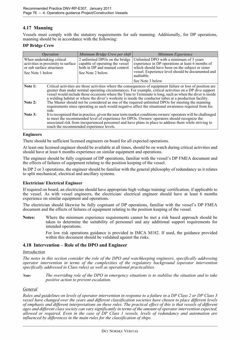
Recommended Practice DNV-RP-E307, January 2011 Page 76 – 4. Operations guidance Project/Construction Vessels
4.17 ManningVessels must comply with the statutory requirements for safe manning. Additionally, for DP operations,manning should be in accordance with the following:DP Bridge Crew
EngineersThere should be sufficient licensed engineers on board for all expected operations. At least one licensed engineer should be available at all times, should be on watch during critical activities andshould have at least 6 months experience on similar equipment and operations. The engineer should be fully cognisant of DP operations, familiar with the vessel’s DP FMEA document andthe effects of failures of equipment relating to the position keeping of the vessel.In DP 2 or 3 operations, the engineer should be familiar with the general philosophy of redundancy as it relatesto split mechanical, electrical and ancillary systems.
Electrician/ Electrical EngineerIf required on board, an electrician should have appropriate high voltage training/ certification, if applicable tothe vessel. As with vessel engineers, the electrician/ electrical engineer should have at least 6 monthsexperience on similar equipment and operations.The electrician should likewise be fully cognisant of DP operations, familiar with the vessel’s DP FMEAdocument and the effects of failures of equipment relating to the position keeping of the vessel.
Notes: Where the minimum experience requirements cannot be met a risk based approach should betaken to determine the suitability of personnel and any additional support requirements forintended operations.For low risk operations guidance is provided in IMCA M182. If used, the guidance providedwithin this document should be validated against the risks.
4.18 Intervention – Role of the DPO and EngineerIntroductionThe notes in this section consider the role of the DPO and watchkeeping engineers, specifically addressingoperator intervention in terms of the complexities of the regulatory background (operator interventionspecifically addressed in Class rules) as well as operational practicalities.
Note: The overriding role of the DPO in emergency situations is to stabilise the situation and to takepositive action to prevent escalation.
GeneralRules and guidelines on levels of operator intervention in response to a failure in a DP Class 2 or DP Class 3vessel have changed over the years and different classification societies have chosen to place different levelsof emphasis and different interpretations on these rules. The practical effect of this is that vessels of differentages and different class society can vary significantly in terms of the amount of operator intervention expected,allowed or required. Even in the case of DP Class 1 vessels, levels of redundancy and automation areinfluenced by differences in the main rules for the classification of ships.
Operation Minimum Bridge Crew per shift Minimum ExperienceWhen undertaking critical activities in proximity to surface or sub surface structuresSee Note 1 below
2 unlimited DPOs on the bridge capable of operating the vessel both in DP and manual control. See Note 2 below.
Unlimited DPO with a minimum of 3 years experience in DP operations at least 6 months of which should have been on the subject or sister vessel. Experience level should be documented and auditable.See Note 3 below
Note 1: Critical activities are those activities where the consequences of equipment failure or loss of position are greater than under normal operating circumstances. For example, critical activities on a DP dive support vessel would include those occasions where the Time to Terminate is long, such as when the diver is inside a welding habitat or where the diver’s worksite is inside the conductor tubes at a production facility.
Note 2: The Master should not be considered as one of the required unlimited DPOs for meeting the manning requirements since operating as such would negative affect the situational awareness required from his side.
Note 3: It is recognized that in practice, given the near term market conditions owners/ operators will be challenged to meet the recommended level of experience for DPOs. Owners/ operators should recognize the associated risk from inexperienced personnel and have plans in place to address them while striving to reach the recommended experience levels.
DET NORSKE VERITAS

Recommended Practice DNV-RP-E307, January 2011 4. Operations guidance Project/Construction Vessels – Page
Examples of the rules and guidelines that have influenced the design of redundancy concepts are given below:-
IMO MSC 645 Section 3.1.4 states under the heading of Functional Requirements,
General: “Redundant components and systems should be immediately available and with such capacity thatthe DP-operation can be continued for such a period that the work in progress can be terminatedsafely. The transfer to redundant components or systems should be automatic as far as possibleand operator intervention should be kept to a minimum. The transfer should be smooth and withinacceptable limitations of the operation.”
DNV rules for the classification of Ships Pt.6 Ch.7 Sec.2 states:
Redundancy: “The DP-system shall be designed with redundancy. A position keeping ability shall bemaintained without disruption upon any single failure. Full stop of thrusters and subsequentstart-up of available thrusters is not considered an acceptable disruption. Component and system redundancy, in technical design and physical arrangement, should inprinciple be immediately available with the capacity required for the DP-system to safelyterminate the work in progress. The transfer to components or systems designed and arrangedto provide redundancy, should be automatic and operator intervention should be avoided.”“Redundancy shall be based upon running machinery. Automatic or manual interventionarranged to improve the position keeping ability after a failure will be accepted. Automaticstart of equipment may be accepted as contributing to redundancy only if their reliability andsimplicity of operation is satisfactory so that they can be brought into operation before positionand heading keeping performance is degraded. Guidance note: The redundancy requirements will not be considered as complied with if basedupon start or restart of generators and/ or thrusters.”
The distinction between ‘improving station keeping capability after a failure’ and ‘contributing to redundancy’should be noted. The latter is intended to mean that the contribution of this equipment or feature can beconsidered when defining the vessel’s post WCF DP capability. The former cannot be considered whendefining this capability thus DP Class 2 and DP Class 3 vessels should not operate in conditions where theywould depend on this equipment to maintain position. However, the feature can be used to improve capability.
Faults requiring operator interventionThe following list comprises known faults and features in DP systems that have been known to requireoperator intervention to prevent escalation of the failure effect or loss of position. Prudent watchkeepingpractices will detect the listed events that require operator (DPO/ engineer) intervention,
— A faulty thruster may respond poorly to DP commands giving rise to a speed/ torque or azimuth predictionerror. The DPO should assess the performance of the thruster and shut it down using the emergency stopif necessary.
— Failure of a thruster to full thrust or uncontrolled rotation will require the DPO to shut the thruster downusing the emergency stop. The process of identifying the faulty thruster may be made more difficult by thefact that all thrusters may be operating at high thrust to counteract the effect of the faulty one. Predictionerrors may indicate which thruster is faulty.
— A DP operator station may fail. The DPO must take control at another operator station. Note that positionand heading should be maintained by the DP controller during this time.
— Seawater cooling systems operated from a single sea chest may block giving rise to low seawater pressurealarms requiring the engineers to transfer to the other sea chest.
— Some vessels have no automation for starting redundant pumps and engineers must monitor the conditionof the plant and intervene following an unexpected stop.
— A heat exchanger in a common freshwater cooling system may become fouled requiring the engineers tochange over to another cooler. This condition may be indicated by high freshwater temperature alarms.
— In some diesel electric designs, failures of fuel control systems or generator excitation systems candestabilise the entire plant if the vessel is operated with a common power system (busties closed). In suchcircumstances the engineers may open the bustie in an attempt to isolate the fault to one side or the other.A load sharing imbalance alarm may assist in identifying the onset of the fault. Note that in somecircumstances the fault may escalate at a rate which precludes effective operator intervention and blackoutmay result.
— A distribution system supplying a DP UPS may fail. The ‘on-batteries’ alarm will indicate to the DPO thatcertain important DP control system consumers may be lost. The DPO or ET can review the UPSdistribution list against sensors, reference systems and operator stations in use to determine whether anyconfiguration changes should be made, for example selecting the other DP controller or OS before theonline controller or OS fails.
— On some DP vessels with a single stern tunnel thruster and two main propellers which depend on therudders to provide redundant athwartships thrust it may be necessary to transfer the tunnel thruster to the
DET NORSKE VERITAS

Recommended Practice DNV-RP-E307, January 2011 Page 78 – 4. Operations guidance Project/Construction Vessels
other power distribution system and restart it in the event that the distribution system supplying one mainprop and the stern tunnel thruster fails.
— On a DP Class 3 vessel, loss of the main DP station will require the DPO to take control at the backup DPstation.
— On a DP Class 2 vessel loss of both DP control systems will require the DPO to take manual control of thevessel at the independent joystick or manual control levers.
— On vessels with two wind sensors a difference alarm may require the DPO to make an assessment of whichwind sensor to use. In the case that one of the wind sensors has failed to ‘high wind speed’ it may benecessary to rapidly deselect the faulty wind sensor before it initiates a drive off depending on the type ofDP control system.
— On vessels with only two gyro compasses a difference alarm may require the DPO to make an assessmentof which gyro to use. A faulty gyro may cause a rapid change of heading if not deselected promptly.
— On vessels with two MRUs a difference alarm may require the DPO to make an assessment of which MRUto use.
— DP control systems employ a range of protective functions designed to reject an errant position referencesystem. Class rules require that three references are in use for DP Class 2 & 3 vessels and two of the threeshould be based on different principles of measurement. This provides a large degree of protection againsta drive off related to a position calculation error but such incidents do occur and DPOs can be expectedto determine which reference systems are responsible and deselect them.
— On vessels with a common fuel supply system, which can be found even on some DP Class 2 vessels, it maybe necessary to change over a fuel filter or isolate a leak to prevent all generators being affected.
— On some vessels with transferable thrusters it may be necessary for the engineers to manually change overauxiliary services for the thruster even if the main supply changes automatically. This changeover, ifrequired, is to prevent the unexpected consequences of failure.
— DPOs should be aware of the thruster and/ or power configuration that is used to activate the ConsequenceAnalysis alarm. It should not be assumed that it is Worst Case Failure. Where it is established that it is notWCF then steps should be taken to ensure that WCF is used as the trigger for a Consequence Analysisalarm.
Measures to reduce the incidence of faults requiring operator interventionThe most effective way to avoid the necessity for operators and engineers to intervene in faults is to design theredundancy concept in such a way that the need for operator intervention is minimised or preferablyeliminated.In general terms, this will often mean adding additional equipment, greater levels of redundancy, automationand increased system segregation to minimise the impact of any failure. Features such as a third wind sensoror a third DP controller allow voting or other protective functions to be used. However, there may be some aspects of DP system design where operator intervention is preferred to any otherform of response. For example, it may not be desirable to automatically transfer control location in responseto a fault. It may be better for the operator to decide where control transfers to by taking control at that station. There is also a risk that poorly designed protective functions will reduce the reliability and availability ofessential equipment such as thrusters and generators. This risk should be considered when applying protectivefunctions to deal with very low probability failure modes.Carefully considering power plant and control system configuration can also reduce the need for operatorintervention. DP Class 2 and 3 vessels should always operate in a redundant/ fault tolerant configuration.Where operator intervention in response to faults is unavoidable then it is extremely important that there areclear and unambiguous alarms and indications to alert the operators to the onset of the fault. It is also of vitalimportance that the required responses to the fault are documented in well-written procedures and practicedso that all DPOs and engineers are familiar with them and can take action in a confident manner.
DET NORSKE VERITAS

Recommended Practice DNV-RP-E307, January 20114. Operations guidance Project/Construction Vessels – Page 79
4.19
DP
Foot
prin
t Plo
ts -
Wor
ked
Exa
mpl
es
Figu
re 4
-1W
orke
d E
xam
ple
1
DET NORSKE VERITAS

Recommended Practice DNV-RP-E307, January 2011 Page 80 – 4. Operations guidance Project/Construction Vessels
Figu
re 4
-2W
orke
d E
xam
ple
2
DET NORSKE VERITAS

Recommended Practice DNV-RP-E307, January 2011 4. Operations guidance Project/Construction Vessels – Page
4.20 Annual DP Trials Test Table Blank – DP Project / Construction Vessel
Guidance note:The blank Annual DP Trials test sheet is on hold pending formal publication of IMCA guidance on Annual DP Trialswhich is under development at the time of preparing this RP. Guidance will be provided in a subsequent revision ofthis RP.
---e-n-d---of---G-u-i-d-a-n-c-e---n-o-t-e---
4.21 Example of SMO and ASOG
Safest Mode of Operation - Name of DP Project/ Construction VesselThis setup applies when the vessel is undertaking umbilical wet store at Nonsuch Offshore Facility - AFI (agreed for implementation)
Date
Condition GREEN DVISORY YELLOW REDNotify Master, Chief Engineer, Winch Control, Offshore Facility and Clients Representative
NO YES YES YES
Action CONTINUE NORMAL OPERATIONS
INFORMATIVE / CONSULTATIVE
STATUS (RISK ASSESS)
CEASE OPERATIONS
INITIATE CONTINGENCY
PLAN
CEASE OPERATIONS PREPARE TO
JETTISON UMBILICAL ON DIRECT ORDER
ONLYBus Ties and Bus Links All bus ties open Any other configuration
Main generators Port - Stbd symmetric (2 or 4 generators running)
Port - Stbd assymmetric or known deficiencies
LLC phase shift transformer
Both connected and functioning correctly
Any other configuration or known deficiencies
All GeneratorsTested at 100% at field arrival or in the past 6
monthsAny other configuration or
known deficiencies
Emergency GeneratorSet to auto start and
connect, available for immediate use
Any other configuration or known deficiencies
Bow Thruster 1 VSD VSD powered from Port side only Powered from Stbd side
Bow Thruster 1 Servo Pump
Powered from HP1 and changeover to HP2 tested
at field arrival
Powered from HP2 or changeover not tested or
problems found
Bow Thruster 1Tested at 50% on each of Port and Stbd side at field
arrival
Powered from Stbd side or opposite to cooling or
operation on Stbd side not tested
Bow Thruster 3 Deployed as azimuth thruster
Operating as tunnel thruster
Thrusters 2, 3, 4 & 5 Tested at 100% at field arrival Any known deficiencies
Thrusters 4 & 5Pitch and lube oil pumps changeover tested at field
arrivalNot tested or problems
found
Thrusters 4 & 5 Both Steering motors/VFD's running
Single steering motor/VFD running
Thrusters Emergency Stops tested at field arrival Any known deficiencies
ThrustersAzimuth, speed and pitch
controls tested for functionality across entire
range at field arrival. Any known deficiencies.
Thrusters All fully operational as above and selected to DP
Any not operating or not selected to DP
Speed of moves inside 500 m zone or carrying out critical activities
From 500 m to 200 m, <= 0.5 m/sec From 200 m to
work location <=0.3 m/secAny other setting
Rate of change of Heading (Within 500 m zone) or carrying out critical activities
<=10 deg/min Any other setting
DET NORSKE VERITAS
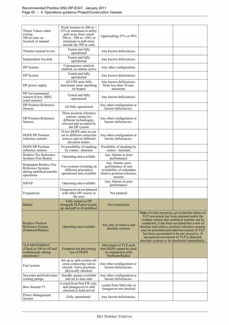
Recommended Practice DNV-RP-E307, January 2011 Page 82 – 4. Operations guidance Project/Construction Vessels
Thrust Values when exiting 500 m zone onJoystick or manual
Work location to 200 m < 25% or minimum to safely
pull away from vessel 200 m - 500 m <50% or minimum to pull away outside the 500 m zone
Approaching 25% or 50%
Thruster manual levers Tested and fully operational Any known deficiencies.
Independent Joystick Tested and fully operational Any known deficiencies.
DP System Consequence analysis enabled, no alarms active Any other configuration.
DP System Tested and fully operational Any known deficiencies.
DP power supplyAll UPS units fully
functional, none operating on bypass
Any known deficiencies. None less than 30 min.
autonomy
DP Environmental sensors (Gyro, MRS, wind sensors)
Tested and fully operational Any known deficiencies.
DP Position Reference Sensors All fully operational Any other configuration or
known deficiencies.
DP Position Reference Sensors
Three position reference sensors, using two
different technologies, selected and accepted by
the DP system
Any other configuration or known deficiencies.
DGPS DP Position reference sensors
If two DGPS units in use set to different correction sources and on different
elevation masks.
Any other configuration or known deficiencies.
DGPS DP Position reference sensors
No possibility of masking by cranes / structure
Possibility of masking by cranes / structure
Relative Pos Reference Systems (Fan Beam) Operating and available Any Alarms or poor
performance
Redundant Relative Pos Reference Systems during umbilical transfer operations
Two systems (working on different principles)
operational and available
Any Alarms, poor performance or non
availability of redundant relative position reference
sensors
HiPAP Operating and available Any Alarms or poor performance
FrequenciesFrequencies in use planned
with other DP vessels in the area
Not planned
RadiusFully tested on DP
alongside TLP prior to pick up and pull in of umbilical
Not tested prior
Relative Position Reference System (Fanbeam/Radius)
Operating and available Any mix of relative and absolute systems
Note: For this operation, given that the observed TLP movement has been minimal under the
weather criteria that umbilical transfer can be conducted, it has been accepted that a mix of
absolute and relative position reference systems may be permitted provided movement of TLP
has been ascertained to be not excessive. If unexpected movement of TLP is detected,
absolute systems to be deselected immediately.TLP MOVEMENT (Check at 100 m off and continuously during operations)
Footprint not preventing use of DGPS
Movement of TLP such that DGPS cannot be used
in conjunction with Fanbeam/Radius
Fuel systemSet up as split system (all cross connecting valves closed). Valve positions
physically checked.
Any other configuration or known deficiencies.
Sea water and fresh water cooling pumps
Standby pumps available and set to auto start
Any other configuration or known deficiencies.
Bow thruster T1Cooled from Port FW only
and changeover to stbd checked at field arrival
cooled from Stbd side or changeover not checked
Power Management System Fully operational. Any known deficiencies.
DET NORSKE VERITAS
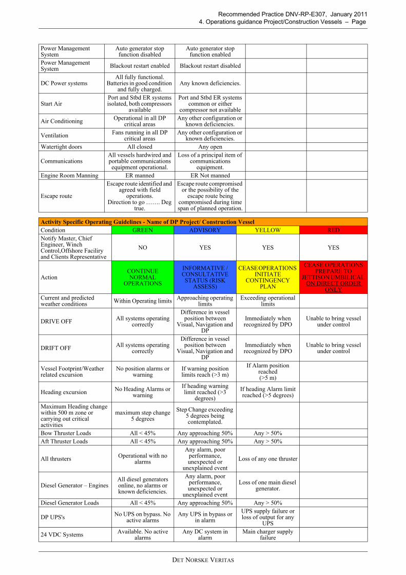
Recommended Practice DNV-RP-E307, January 2011 4. Operations guidance Project/Construction Vessels – Page
Power Management System
Auto generator stop function disabled
Auto generator stop function enabled
Power Management System Blackout restart enabled Blackout restart disabled
DC Power systems All fully functional.
Batteries in good condition and fully charged.
Any known deficiencies.
Start AirPort and Stbd ER systems isolated, both compressors
available
Port and Stbd ER systems common or either
compressor not available
Air Conditioning Operational in all DP critical areas
Any other configuration or known deficiencies.
Ventilation Fans running in all DP critical areas
Any other configuration or known deficiencies.
Watertight doors All closed Any open
CommunicationsAll vessels hardwired and portable communications equipment operational.
Loss of a principal item of communications
equipment.
Engine Room Manning ER manned ER Not manned
Escape route
Escape route identified and agreed with field
operations. Direction to go ……. Deg
true.
Escape route compromised or the possibility of the
escape route being compromised during time span of planned operation.
Activity Specific Operating Guidelines - Name of DP Project/ Construction VesselCondition GREEN ADVISORY YELLOW REDNotify Master, Chief Engineer, Winch Control,Offshore Faciliry and Clients Representative
NO YES YES YES
ActionCONTINUE NORMAL
OPERATIONS
INFORMATIVE / CONSULTATIVE STATUS (RISK
ASSESS)
CEASE OPERATIONS INITIATE
CONTINGENCY PLAN
CEASE OPERATIONS PREPARE TO
JETTISON UMBILICAL ON DIRECT ORDER
ONLYCurrent and predicted weather conditions Within Operating limits Approaching operating
limitsExceeding operational
limits
DRIVE OFF All systems operating correctly
Difference in vessel position between
Visual, Navigation and DP
Immediately when recognized by DPO
Unable to bring vessel under control
DRIFT OFF All systems operating correctly
Difference in vessel position between
Visual, Navigation and DP
Immediately when recognized by DPO
Unable to bring vessel under control
Vessel Footprint/Weather related excursion
No position alarms or warning
If warning position limits reach (>3 m)
If Alarm position reached (>5 m)
Heading excursion No Heading Alarms or warning
If heading warning limit reached (>3
degrees)If heading Alarm limit reached (>5 degrees)
Maximum Heading change within 500 m zone or carrying out critical activities
maximum step change 5 degrees
Step Change exceeding 5 degrees being contemplated.
Bow Thruster Loads All < 45% Any approaching 50% Any > 50% Aft Thruster Loads All < 45% Any approaching 50% Any > 50%
All thrusters Operational with no alarms
Any alarm, poor performance, unexpected or
unexplained eventLoss of any one thruster
Diesel Generator – EnginesAll diesel generators online, no alarms or known deficiencies.
Any alarm, poor performance, unexpected or
unexplained event
Loss of one main diesel generator.
Diesel Generator Loads All < 45% Any approaching 50% Any > 50%
DP UPS's No UPS on bypass. No active alarms
Any UPS in bypass or in alarm
UPS supply failure or loss of output for any
UPS
24 VDC Systems Available. No active alarms
Any DC system in alarm
Main charger supply failure
DET NORSKE VERITAS

Recommended Practice DNV-RP-E307, January 2011 Page 84 – 4. Operations guidance Project/Construction Vessels
DP Operator Control Station
Both operating normally, no alarms.
Any alarm, poor performance, unexpected or
unexplained event
Loss of one operator station
Dynamic positioning controllers
Both operating normally, no alarms.
Any alarm, poor performance, unexpected or
unexplained eventLoss of one DPC
PMS/IAS Field Termination Cabinets
All operating normally, no alarms.
Any alarm, poor performance, unexpected or
unexplained eventLoss of one PLC
DP Networks Both operating normally, no alarms
Any alarm, poor performance, unexpected or
unexplained eventLoss of one network Total loss of networks /
DP control
Gyros 3 gyros selected and accepted by DP Any gyro alarm. One operational gyro
remaining
MRUs 2 MRUs selected and accepted by DP Any MRU Alarm One operational MRU
remaining
Wind sensors Operational with no alarms Loss of wind sensor
Loss of both wind sensors in high wind/
gusting wind conditions.
DP Position reference sensors
Three position reference sensors, using
two different technologies, accepted by the DP system and in
use.
Any alarm, poor performance, unexpected or
unexplained event
One remaining operational position
reference system
Redundant Relative Pos Reference Systems during umbilical transfer operations
Two systems (working on different principles)
operational and available
Any Alarms, poor performance or non
availability of redundant relative position reference
sensors
Single relative pos ref
PMS/IAS Control systems All operating normally, no alarms.
Any alarm, poor performance, unexpected or
unexplained event
Loss of one major system component
Machinery space ventilation, DP critical space Air Conditioning
Fully operational. Loss or reduced capacity of any system
Imminent loss of due to over temperature of any
DP equipment.
Loss or problem with any essential Communications (DP / ECR / Winch CONTROL/ROV/TLP)
Redundant Communications One system remaining No comms
Fire No fire alarms, or fire reported Any fire alarm/report Fire confirmed
Flood No bilge alarms active, no reported flooding. Multiple bilge alarms Flood confirmed
Collision (errant vessels)No collision imminent /
minimum approach >500 m
Minimum approach will be < 500 m If collision possible Collision Imminent
DET NORSKE VERITAS

Recommended Practice DNV-RP-E307, January 2011 4. Operations guidance Project/Construction Vessels – Page
SIMOPS - Name of DP Project/ Construction Vessel - undertaking umbilical wet store at Nonsuch TLPCondition GREEN ADVISORY YELLOW REDNotify Master, Chief Engineer, Winch Control, Offshore Facility and Clients Representative
NO YES YES YES
ActionCONTINUE NORMAL
OPERATIONS
INFORMATIVE / CONSULTATIVE STATUS (RISK
ASSESS)
CEASE TYING IN OPERATIONS
INITIATE CONTINGENCY
PLAN
CEASE OPERATIONS PREPARE TO
JETTISON UMBILICAL ON DIRECT ORDER
ONLYChange from Green DP Status of any other vessel in the field Green Advisory Advisory Advisory
Procedure agreed and understood by all involved. Toolbox talks and safety briefings complete.
Briefings complete.Operation continues
without major deviation from planned
procedure.
Major deviation from procedure
Situation arises where the risk of personnel injury or a pollution
event can be envisaged.
Comms/interaction with other vessels
Vessels operating normally with no known problems
Comms problemor
Possible position conflict
No comms or
Definite position conflict
Comms between DP Desk, Pipe lay control, Deck Forman, TLP Platform rigger foreman.
Redundant comms Comms problem One comms system remaining
Comms with Field Control Room Redundant comms Comms problem One comms system remaining
Completed by
Printed name
On behalf of Client
Printed name
DET NORSKE VERITAS

Recommended Practice DNV-RP-E307, January 2011 Page 86 – 5. Operational guidance Logistic Vessels
5. Operational guidance Logistic Vessels5.1 IntroductionThis chapter contains DP operational guidance, specific for Project and Construction Vessels. For overviewand full appreciation, this information is completed with the general management information as already wasgiven in chapter 2. For distinction, the general information is printed in regular text, and the specific operationalguidance is in italics and/or grouped under Guidance notes.It is acknowledged that the guidance provided on the themes in this chapter may be to a greater level of detailthan what is required for logistics vessels. This has been consciously done with a view to enhance awarenessof issues related to DP operations and cover a broader DP community.
5.2 DP Operational Documentation
5.2.1 GeneralIt is recommended that DP vessel owners/ operators should maintain the documentation listed in the tablebelow and should develop and implement associated processes for the purposes of:
— ensuring the safe and effective management of the vessel in DP— ensuring the technical suitability of the vessel for each DP activity it is required to carry out— determining the configuration for the safest mode of operation and the task appropriate mode— understanding the vessel’s station keeping capabilities following the worst case failure— ensuring compliance with appropriate standards and guidelines— providing training and familiarization material to vessel crews.
5.2.2 Recommended Documentation Current versions of the documents in the list below should be kept on board and, in addition, where feasible, atthe shore based centers of technical management. Documents that have been superseded should be clearlymarked and kept separate from current versions. Documents may be in electronic or, hard copy format or, both.
No. Document Management Guidance Operational Guidance1 DP System FMEA
or FMECA To be kept up to date, incorporating all modifications and additions since original study, if not in the document itself, then by other traceable means. All records to be kept on board.
Modifications and additions should be covered by a MOC process that triggers updating the FMEA.
2 DP FMEA Proving Trials
To be conducted to prove initial DP FMEA and at other times to prove modifications and additions to the DP system. DP FMEA Proving Trials should be repeated every five years. Findings and recommendations to be addressed in accordance with their criticality. All records to be kept on board.
Modifications and additions that should be proven by testing include all those that have directly effect or, potential to affect the performance or redundancy of the DP system. This will include protective, detection and monitoring functions.
3 Annual DP Trials To be conducted annually. Findings and recommendations to be addressed in accordance with their criticality. Previous trials reports and associated close out documentation to be kept on board.
The tests in the Annual DP Trials should be designed to prove system redundancy, as defined in the DP FMEA, system and equipment performance and functionality, to validate repairs and preventive maintenance, to test the operation of protection and detection devices and responses so as to demonstrate that the vessel’s DP system remains fit for purpose.
4 DP Capability Plots
Hard copy DP Capability Plots relevant to the vessel’s areas of operations to be readily accessible to DPOs at the DP control location.
Capability plots to be validated/ recalculated, as required, to ensure that they are suitable for the environmental conditions where the DP operations are to take place, in particular in respect of current speeds. This requirement to validate/ recalculate applies also in cases where DP vessel performance is affected by operational constraints imposed by the activity, such as in the case of a pipelay vessel with horizontal loads, logistics vessels retrofitted with additional accommodation modules (temporary or permanent).
5 DP Footprints Hard copy DP Footprint Plots to be taken by DPOs. See Note 1 at end of table.
DP Footprint Plots should be taken regularly in various power/ thruster combinations, including fully intact and worst case failure and also in various environmental conditions.
DET NORSKE VERITAS

Recommended Practice DNV-RP-E307, January 2011 5. Operational guidance Logistic Vessels – Page 87
6 Service reports concerning the DP system
Complete history of service reports to be filed and kept on board
There should be a process where the open items are highlighted, tracked and closed out.
7 Details of all DP related modifications and additions
Records of all DP related modifications and additions to be kept on board complete with interface and testing information. See Note 2 at end of table.
A structured FMEA and Proving Trials approach should be used to integrate modifications and additions into the existing DP system and its associated equipment. New and modified software should be subjected to a thorough validation process, especially to avoid the acceptance of erroneous values. Known instances as examples pipe tensioner software that accepted a sudden increase of pipe tension from 100 t to 300 t (erroneous input), software for thruster control that increased the command to the thruster to match the faulty feedback.It is not enough to focus on the functionality of modifications and additions. It is equally important to fully understand the functional design spec and the dependencies and consequences of fault or failure.
8 Vessel audit reports and DP audits and inspection reports.
Complete history of all audit reports, DP audits and inspection reports, including findings and close outs to be kept on board
There should be a process where the open items are highlighted, tracked and closed out.
9 DP Operations Manual
Vessel Specific DP Operations Manual 1), to be readily accessible at the DP control location and used by the DPOs as a reference for conducting DP operations.
It is recommended that owners/ operators develop a standardised table of contents for vessel specific DP Operations Manuals in their fleet. Modifications and amendments to the DP Operations Manual should be subject to MOC processes, including changes to vessel specific checklists.
10 DP Incident Reports
Records of all DP station keeping and other DP related incidents to be kept on board, including investigation records and close outs.
All DP incidents should be investigated to an extent that reflects the potential consequences of the incident.
11 DP Mobilization/ DP Field Arrival/ Trials Procedures (Bridge and Engine Room)
Records of DP Mobilization Trials and DP Field Arrival Checklists to be kept on board for the period set by the owner/ operator and, where relating to a DP incident permanently stored in retrievable archives.
DP Trials and Checklists should be vessel specific and be developed from detailed information contained in the DP FMEA. They should confirm vessel performance, particularly following worst case failure, and that the vessel’s DP system is set up properly and provides the required level of redundancy.
12 DP Location and Watchkeeping checklists(Bridge and Engine Room)
Records of all DP Location and Watchkeeping Checklists to be kept on board for the period set by the owner/ operator and, where relating to a DP incident, permanently stored in retrievable archives.
As above
13 DP related drills and emergency response drills
Records of DP related drills and emergency response drills to be kept on board in retrievable archives.
DP drills can be developed from fault and single point failure scenarios addressed in the vessel’s DP FMEA. The drills should also cover extreme events that are outside the scope of the DP FMEA.The outcomes from these drills should be used in the development of DP emergency response procedures and used as training material for DP personnel. These records may be used in a cycle of continuous improvement.
14 DP fault log Records of all faults related to the DP system to be kept on board permanently in retrievable archives.
DP faults should be recorded as soon as possible after they are discovered and action/ investigation taken appropriate to the potential consequences of the fault on the vessel’s station keeping ability.
No. Document Management Guidance Operational Guidance
DET NORSKE VERITAS

Recommended Practice DNV-RP-E307, January 2011 Page 88 – 5. Operational guidance Logistic Vessels
Note 1: It is acknowledged that DP Footprint Plots may be less relevant for DP MODUs than for other DPvessel types.
Note 2: Owners/ operators should keep adequate records and documentation relating to modifications andadditions that could have an effect on the DP system, especially interfaces between equipmentfrom different vendors. This is as relevant for equipment whose primary function lies outside theDP system, such as an Emergency Shutdown Systems (ESD), pipe tensioner systems and firemonitor systems as it is for DP equipment, such as propulsion, position references and sensors.All modifications and additions should be subjected to FMEA type analysis and undergo ProvingTrials type testing. In addition, modifications and additions are typically subject to class approvaland inspection.
15 DP Data Logging Where the vessel has DP data logging facilities electronic records should be kept on board for the period set by the owner/ operator and, where relating to a DP incident, permanently stored in retrievable archives.
DP data loggers perform an important function in helping to determine root causes of faults or failures. It is recommended that DP data logging function is included as part of the DP system design spec, DP data loggers should be commissioned and operational before DP system Customer Acceptance Trials (CAT) are carried out. The DP data logger should be incorporated in the SMO and running at all times when in DP. If not, this should trigger an Advisory condition, i.e. BLUE.There should be specific procedures for the operation and analysis of output from the DP data logger. This should include clear instructions on how and where the records are kept. Retention of data logging data should not be limited by time.Note:- It is acknowledged that DP data loggers are not the norm on Logistics vessels. Owners are encouraged to consider the benefits to be derived by installing DP data loggers on their vessels.
16 DP alarm printer readouts
Hard copy records of the DP alarm printer readout to be kept on board for the period set by the owner/ operator and, where relating to a DP incident, permanently stored in retrievable archives.
Owners/ operators frequently require DP alarm printer readouts to be kept for a duration indicated in their Management Systems. Where this is not specified, owners are encouraged to specify retention times, Alarm printouts relating to a DP incident or contractual dispute are to be permanently stored in retrievable archives.
17 DP familiarisation and competency records
All records relating to vessel specific DP familiarisation and competency for DPOs, engineers and electricians to be kept on board permanently in retrievable archives.
Owners/ operators should implement an in-house DP competency assurance process for key DP personnel which is structured, systematic and progressive. It should be noted that DPO certification is only one element in the competency assurance process. Owners/ operators are recommended to make use of facilities and training programmes available to the DP sector, such as the Powersim program for advanced DPO training of power plant fault conditions, where DPOs are given detailed instruction and training in identifying and responding to power system faults. Examples include DPO intervention averting an underfrequency induced blackout on closed bus system by the DPO taking control of thrusters and biasing to increase load.
18 Résumés and vessel specific work records of all key DP personnel
Résumés of all key DP personnel, copies of certification and qualifications, records of DP watchkeeping hours to be maintained on board. Original DPO certificates and DP Log Books to be held by the DPOs onboard the vessel.
1) The vessel specific DP Operations Manual is additional to the DP control system manufacturer’s Operator Manual
No. Document Management Guidance Operational Guidance
DET NORSKE VERITAS

Recommended Practice DNV-RP-E307, January 2011 5. Operational guidance Logistic Vessels – Page 89
5.3 DP ClassIt is recommended that DP vessels with at least the following DP equipment class notations are used for thefollowing activities. Regulations, contractual specifications and/ or harsh environmental or other localconditions may require a higher class.
Note 1: The vessel’s DP system should normally be set up and operated to deliver the intent of the DPclass notation. However, on occasion and after a proper assessment of the risks, the vessel may beset up in accordance with the requirements of the Task Appropriate Mode.
Note 2: For operations close to another vessel or installation the equipment class should be 3 or equivalent.Class 2 may be accepted based on considerations of procedures, equipment and consequenceanalysis
Note 3: It is noted that there have been standards developed outside the IMO DP equipment classsystematics where an identical (or higher) level of redundancy has been realized based on adifferent philosophy and system approach.
Guidance note:A detailed risk analysis will be required if the vessel is to operate in a task appropriate mode (TAM) that providesless redundancy than that provided by the vessel’s DP equipment class notation. The detailed risk analysis should consider the consequences of loss of position relevant to the activity.
---e-n-d---of---G-u-i-d-a-n-c-e---n-o-t-e---
5.4 DP FMEAThe DP vessel’s DP FMEA is the most important technical document in the list of required documents. Therequirement for a DP FMEA has its origins in IMO MSC/Circ 645 (1994) “Guidelines for Vessels withDynamic Positioning Systems”. These benchmarking guidelines provide the foundation for all subsequent DPrules, regulations and guidance issued by Class and other industry bodies, such as IMCA.The IMO Guidelines require all DP vessels to be subjected to survey and testing in accordance with IMO’sspecified guidelines. This includes initial and periodic complete survey and testing of all systems andcomponents required to keep position after single failures associated with the vessel’s assigned DP equipmentclass. The periodic component in the IMO Guidelines requires the complete survey and testing to be repeated everyfive years to ensure full compliance with applicable parts of the guidelines. In addition compliance with IMO Guidelines requires survey and testing after defects are discovered andcorrected and, after a DP related accident and, whenever significant repairs or alterations are carried out, so asto demonstrate full compliance with applicable parts of the guidelines. The IMO Guidelines do not make clear distinction between vessels of different DP equipment class.This IMO requirement has been interpreted by the DP community such that the survey requirement is met bya DP FMEA (or FMECA1)) and the testing requirement by DP FMEA Proving Trials.
1) Unless expressly stated in this Guidance document a FMECA is interchangeable with an FMEA.
Application on DPMinimum
Recommended DP Equipment Class
(See Note 1 below)Remarks
Drilling 2 Diving 2 Pipelay 2 Umbilical Lay 2 Lifting 2 Accommodation 2 Shuttle Offtake 2 ROV Support (Open Water) 1 ROV Support (Close Proximity - Surface/ Subsea)
2
Floating Production 2 Seismic and Survey vessels (Open water- outside 500 m zone)
** ** Class in accordance with contractual requirements
Well Stim 2* * Vessels of lesser Class may be used with the appropriate structured risk identification and mitigation measures in place.
Logistics Operations 2*
DET NORSKE VERITAS

Recommended Practice DNV-RP-E307, January 2011 Page 90 – 5. Operational guidance Logistic Vessels
Accordingly, all DP vessels of DP Class 2 or 3 are required to have a Class approved and stamped DP FMEAand DP FMEA Proving Trials.
Definitions: An FMEA is a systematic analysis of systems and sub-systems to a level of detail that identifiesall potential failure modes down to the appropriate sub-system level and their consequences. AFMECA is an extension of an FMEA that adds a risk assessment of each failure mode to determineits criticality.
In addition to complying with the IMO Guidelines and the relevant DP rules of the vessel’s Classification Societythe DP FMEA should achieve the standards of detail and analysis contained in the following industry guidance;
— IMCA M166 “Guidance on Failure Modes and Effects Analysis”— IMCA M178 “FMEA Management Guide”— IMCA M04/04 2004 “Methods of Establishing the Safety and Reliability of DP Systems”
Note: FMEAs are a requirement to obtain DP Class 2 and 3 notation. Whilst not stipulated as a classrequirement for DP 1 vessels owners/ operators are encouraged to subject their DP 1 vessels to theDP FMEA process.
Note: Particular attention should be paid in the DP FMEA to the interfaces between the DP system andother systems that have the potential to affect the DP system, such as where the vessel is fittedwith an Emergency Shut Down (ESD) system, pipe tensioner system or fire monitor system.
Key DP personnel, including the vessel Master, DPOs, Engineers and Electricians should have a detailedknowledge of the DP FMEA and should use the information provided to be fully informed about thecapabilities and limitations of the vessel’s DP system. The results from a DP FMEA, in particular issues related to the vessel’s worst case failure and significant singlepoint failures, should be used in the formulation of operational, emergency response and planning decisions.
Guidance note:These Guidance Notes on DP FMEAs are intentionally brief. They give a concise overview of the underpinningphilosophy, analytical processes and the technical content of a DP FMEA. Relevant IMCA guidance, referred to inthis section, should be consulted to gain a more detailed understanding. A DP FMEA should encompass the following:-
— identify worst case failure design intent (WCFDI) and worse case failure (WCF),— identify the equipment or subsystem, mode of operation and the equipment,— Identify all potential failure modes and their causes,— identify the significant single point failures,— identify potential hidden failures, — identify potential configuration errors,— evaluate the effects on the system of each failure mode,— Identify measures for eliminating or reducing the risks associated with each failure mode,— identify trials and testing necessary to prove the conclusions,— be updated after any major modifications and proving trials have been conducted,— be subject to review and update as necessary, once every five years. The review should take account of new
equipment and hardware/ software updates, new developments in analysis and new knowledge acquired in theintervening period,
— take account of action items from DP FMEA Proving Trials, Annual DP Trials, audits and incidents which havebeen or, are in the process of being, closed out,
— take account of non DP systems/ auxiliary/ external systems that have interfaces with, and potential impact onDP and station keeping. These systems should be subjected to the FMEA and Proving Trials approach forsoftware, hardware and interfaces thus ensuring the integrity of the DP system and proper integration with DP,
— take account of common mode failures that are otherwise liable to be overlooked, such as the effects ofhydrocarbon gas on engine control and safety systems, which can cause diesel engines to accelerate out ofcontrol resulting in catastrophic mechanical failure and potential for black out.
— be presented as a narrative analysis of DP related systems and subsystems covering the above points (i.e.redundancy concept, hidden failures, configuration errors, etc.) and be supported by sketches and drawings,
— for DP Class 3 vessels, should consider the effects of fire and flood, not only from a compartment analysisperspective but also, where significant, at the subsystem level, e.g. the effects of fire and flood on ESD controllines and push buttons.
Note: Where the redundancy concept relies on inter-switching mechanisms, the reliability and effectivenessof these mechanisms should be proven and fully documented in the DP FMEA.
Note: The DP FMEA should contain an analysis of the DP control system I/Os to verify that it is consistentwith the redundancy concept and should be proved at DP FMEA Proving Trials.
Note: The DP FMEA should address the ESD function (if fitted), in particular the various issues relating tothe status of post activation battery power supplies (UPS). Appropriate guidance is given in section 6.6of IMCA M196, “Guidance on the Design, Selection, Installation and Use of UPS onboard Vessels”.
Note: The findings from a DP FMEA and Proving Trials should be categorised into A, B or C. Categoriesshould be clearly defined. Appropriate definitions are as follows;A For immediate attention. The failure effect exceeds worst case failure design intent or is non
DET NORSKE VERITAS

Recommended Practice DNV-RP-E307, January 2011 5. Operational guidance Logistic Vessels – Page 91
compliant with specified rules and guidelines, e.g. Class rules. Improvement is required for compliancewith class.B For attention when reasonably convenient. The failure effects equal worst case failure design intentbut there is an opportunity to reduce the failure effect as reasonable cost. A cost benefit analysis isrecommended.C For consideration. Comments and observations related to good practice.
A FMECA is an extension of an FMEA that adds a risk assessment of each failure mode to determine its criticality.Criticality is derived from an assessment of the probability that a particular failure will occur combined with theseverity of the failure if it does occur.A DP FMECA should encompass all of the listed points in DP FMEA above and, in addition, include the following steps;
— determine the severity of each failure mode,— determine the probability of occurrence of each failure mode (using qualitative or reliable MTBF data),— determine and rank the criticality of the identified failure modes from highest to lowest,— determine a strategy for dealing with the ranked criticalities so that remedial measures are directed
appropriately in accordance with the criticality ranking,
The Criticality Analysis should be presented in tabulated form making using of risk matrices that comply withrecognised international standards such as those given in IMCA M166 or IEC 60812.
Note: The closing out of action items should be well documented and auditable.
The following IMCA Guidelines address the above considerations in various levels of detail; M166, M178, M04/04and Annex.A DP FMEA should be referred to at the following times;
— conducting task based DP operational risk assessments, where key personnel involved should have detailedknowledge of the DP FMEA,
— determining the DP vessel’s Safest Mode of Operation (SMO), e.g. where the unavailability of equipment mayreduce the vessel’s DP station keeping ability,
— determining the DP vessel’s Activity Specific Operating Guidelines (ASOG), e.g. where equipment performanceapproaches or exceeds predetermined limits,
— determining the vessel’s Task Appropriate Mode, when applicable and warranted by the specific DP operations,— developing planned maintenance schedules, taking account of the impact of taking systems or equipment out of
service— developing the vessel’s DP Operations and Emergency Response manuals and procedures,— developing DP trials programs and checklists, ensuring that the single point failures identified in the DP FMEA
are covered in the trials and checklists.
Note to Owners: In the case of newbuilds, if DP FMEAs are within the shipyard’s scope of supply, owners arerecommended to ensure that there are contractually binding agreements for the FMEA to meetspecifications set out in IMCA Guidelines, M166. M178, M04/04 and Annex and preferably becarried out by an independent third party DP FMEA practitioner.
Cautionary Note: DP FMEAs that are solely focused on attaining class notation and class approval may notalways meet guidance standards stipulated in those IMCA Guidelines.
---e-n-d---of---G-u-i-d-a-n-c-e---n-o-t-e---
5.4.1 DP Capability PlotsDP Capability Plots should be calculated for the vessel. Guidance is provided on DP Capability Plots in IMCAM140 Rev 1, “Specification for DP Capability Plots”.These theoretical plots are calculated from detailed information of the vessel’s hull and superstructure form andavailable thruster power. The calculations should use environmental data (seastate, wind and current)appropriate to the area in which the DP vessel is to operate. These plots should show the limiting wind speed 360 degree envelopes for the scenarios below, where eachpoint on the envelope represents the wind speed at which it is calculated that the vessel will be unable tomaintain position in DP. DP Capability Plots should include the following scenarios at current speeds of 0, 1 and 2 knots, or at othercurrent speeds that are representative of the location in which the DP vessel is to operate:
— Fully intact power generation and thrusters.— Loss of most effective thruster(s).— Following the worst case failure.
Note: The DP Capability Plots should be provided in a format that is intuitive to the user on board (e.g.Polar Plot).
Guidance note:DP Capability Plots that do not cover Worst Case Failure are incomplete. DP Capability Plots that do not take into
DET NORSKE VERITAS

Recommended Practice DNV-RP-E307, January 2011 Page 92 – 5. Operational guidance Logistic Vessels
account thruster interaction, (thruster-thruster, thruster-hull), thruster degradation and thruster barred zones areincomplete.Owners/ operators should note that it is important to provide a detailed scope of work to whoever is to generate theDP Capability Plots for the vessel. Experience has shown that those who generate the DP Capability Plots, such asthe DP system manufacturers, may not include the Worst Case Failure, unless specifically instructed to do so. This isparticularly relevant where the DP Capability Plots are included in the shipyard’s scope of supply for newbuilds. DP Capability Plots may have to be recalculated from time to time during the lifetime of a DP vessel. For example,the installation of new equipment, such as a crane or an accommodation module on deck will alter the vessel’s outline,which, in turn, will alter the wind effect on the vessel. In these circumstances the DP Capability Plots should be re-calculated to take account of the changes. DP Capability Plots may also have to be recalculated for thruster configurations where, due to unforeseen faults orfailures or, due to essential maintenance requirements, one or more thrusters are no longer available. Where notalready covered by existing calculations the revised DP Capability Plots should cover the following cases for the newthruster condition; i.e. the new fully intact condition, the new loss of most effective thruster(s) and the new worst casefailure condition. DP Capability Plots should be readily available to the DPOs at the DP control console. DPOs should consult DP Capability Plots as a matter of course whilst the vessel is conducting DP operations. DPOs should be fully familiar with the limits given in the DP Capability Plots for the fully intact thrusterconfiguration, for loss of most effective thruster and for worst case failure. DPOs should be careful when estimating the current force acting on the vessel and relating it to the DP CapabilityPlots. DPOs should be aware that the current force generated by the DP control system is the residual external forceacting on the vessel that cannot be measured. When wind speeds are low an attendant vessel, if available, could beused to estimate current by going into drift mode. DP Capability Plots should be used by DPOs and other key DP personnel as a reference in the planning phases whendetermining the vessel’s environmental operational limits for the ASOG. Where the DP Capability Plots show anundue level of heading limitations this may restrict the vessel’s operating range. This is not uncommon on vessels,such as DP tankers, that have good fore and aft thrust capability but limited thwartship capability. It should be remembered that DP Capability Plots are theoretical calculations and that, wherever possible,opportunities should be taken to validate the DP Capability Plots by taking DP Footprint Plots. See below.
---e-n-d---of---G-u-i-d-a-n-c-e---n-o-t-e---
5.5 DP Footprint PlotsDP Footprint Plots should also be produced on board. DP Footprint Plots are not theoretical. They are actualmeasurements of the vessel’s DP station keeping performance in the actual environmental conditions andthruster configuration at the time the plot was taken. DP Footprint Plots should be taken whenever opportunitiesarise, such as during standby periods, weather downtime or on arrival at the field. Plots should be taken for thethruster configurations used in the DP Capability Plots, i.e. fully intact, loss of most effective thruster(s) andafter worst case failure.Some DP systems have a software application that produces DP Footprint Plots electronically. DPOs can alsoproduce DP Footprint Plots by manual methods using a plotting sheet.DP Footprint Plots serve two main purposes.
— They provide a scatter plot of vessel positions at regular intervals around the required set position (thisshows accuracy of station keeping)
— They also provide comparison points on the limiting wind speed envelope given in the theoretical DPCapability Plots (this shows wind speeds at which it was seen that the vessel was unable to maintainposition, thus validating or contradicting the theoretical DP Capability Plots for the various thrusterconfigurations.)
DP Footprint Plots serve other purposes, including learning and familiarisation opportunities for DPOs and inproviding snapshots of vessel station keeping behaviour for specific locations and activities. Theoretical DP Capability Plots and DP Footprint Plots combine together to enhance knowledge andunderstanding of the vessel’s DP station keeping ability.
Note: DP Footprint Plots originated in harsh weather regions, such as in the North Sea. The plots areused to gain a better understanding of the vessel’s actual station keeping performance andlimitations in intact and, in various degraded thruster configurations, including worst case failure,whilst the vessel is being subjected to real environmental forces.
It is acknowledged that DP Footprint Plots may be of less relevance to DP MODUs.Guidance note:Manual DP Footprint Plots are generated in the following manner.
— Use a proforma plotting sheet, comprising a 360 degree polar plotting diagram, vessel outline with thrustersindicated and space for vessel specific position reference systems and environmental data. Refer to plotting sheetsin Sec. 5.19.
DET NORSKE VERITAS

Recommended Practice DNV-RP-E307, January 2011 5. Operational guidance Logistic Vessels – Page 93
— The vessel should be in auto DP. Record wind, waves and current on the plotting sheet, drawing appropriate vectors.— Record thruster configuration on the plotting sheet.— Record the rate of turn and speed of moves. It is suggested that the following values are applied, 10 deg/min and
0.3 m/sec, respectively, to prevent misleading results. — Observe position excursions from the intended position by the most appropriate means, plotting the vessel’s
position regularly, e.g. every 30 seconds.
Sec.5.19 contains two worked examples. Both worked examples are for the same DP vessel and in the sameenvironmental conditions. Wind was 45 to 50 knots from 225 degrees with a corresponding wave height of 6 m.Current was 1 coincident at 1 knot. Example 1 shows a DP Footprint Plot for the vessel’s fully intact condition with all four thrusters operational. Theplot shows that the vessel was able to maintain position within +/- 2 meters with the wind and sea on the port quarter.Example 2 shows a DP Footprint Plot for the vessel’s worst case failure condition with only two thrusters operational.The plot shows that the vessel was unable to maintain position with the wind and sea on the port quarter. Example 2 - The known circumstances at the time of taking the DP Footprint Plot, of wind, wave height and thrusterconfiguration, in which the vessel failed to maintain position, can be compared against the environmental envelopeplotted on the theoretical DP Capability Plot for worst case failure. They should be similar in that the DP CapabilityPlot should also show that vessel will be unable to maintain position in conditions where a 45 to 50 knots wind is onthe port quarter. If there is a significant difference between the two, particularly if the DP Capability Plot shows thatthe vessel can maintain position in the given condition, then it may be necessary to pull in the limiting wind envelopeon the DP Capability Plot to the upper wind speed determined by the DP Footprint Plot for these conditions.
Cautionary Note: The DP Footprint Plot positions will contain systematic position reference errors.
---e-n-d---of---G-u-i-d-a-n-c-e---n-o-t-e---
5.6 Position Reference Systems and SensorsThe DP vessel should be equipped with suitable position reference and sensors in accordance with the vessel’sDP class notation and operational requirements. Position reference systems should be selected with dueconsideration to operational requirements, both with regard to restrictions caused by the manner of deploymentand expected performance in working situations.Position reference systems comprise absolute and relative systems. An absolute system gives vesselgeographical position. A relative system gives vessel position in relation to a non-fixed reference. A relativesystem can be used as an absolute system if installed on a point that is a fixed geographical position. And, anacoustic absolute system can be used as a relative system if attached to a non-fixed asset. The following are the most common position reference systems in use.
Note 1: Class rules give minimum requirements for the number of position references. Where operationaluptime is one of the key success factors the benefit gained by consciously exceeding the minimumrequirements are to be evaluated. Other benefits of exceeding minimum requirements includegreater redundancy and improved station keeping performance.
Note 2: It could be debated that Taut Wire and Acoustic Position reference systems are relative positionreference systems. For purposes of this document, absolute indicates that this position referencesensor is independent of another fixed or floating offshore structure.
Caution: Additional position reference systems should be based on different principles. It is generally notrecommended to use multiple (>2) satellite based systems in conjunction with other positionreference systems as this may result in skewed weighting in favour of multiple satellite systems.
Caution: DP reference systems sensitive to interferences from the vessels radars, radios etc. should not beused during critical operations such as sub-sea operations.
Guidance note:The reference system may be subject to contract specifications/ oil major requirements. Notwithstanding these,operational guidance on position reference systems and sensors is given in the table on the next page.
Absolute DGNSS (DGPS and GLONASS)Acoustic (USBL, SBL, LBL)Taut wire (see Note 2)
Relative ArtemisLaser (e.g. Fanbeam, Cyscan)Radar (e.g. RADius, RadaScan)DARPS
DET NORSKE VERITAS

Recommended Practice DNV-RP-E307, January 2011 Page 94 – 5. Operational guidance Logistic Vessels
Re
com
men
ded
Abso
lute
Pos
ition
Ref
eren
ce S
yste
ms
Reco
mm
ende
d Re
lativ
e Po
sitio
n Re
fere
nces
Sys
tem
s if i
n cl
ose
prox
imity
to a
n of
fsho
re st
ruct
ure
Sens
ors
App
licat
ion
on
DP
GPS
DG
NSS
(D
GPS
+
GLO
NA
SS)
(See
Not
e 2
belo
w)
SBL
(See
N
ote
1 be
low
)
USB
L/
SSB
L(S
ee
Not
e 1
belo
w)
LBL
(See
N
ote
1 be
low
)
Taut
W
ire
(See
N
ote
12
belo
w)
Min
N
umbe
r (S
ee
Not
e 3
belo
w)
Arte
mis
Lase
rR
adar
Gan
gway
D
AR
PS
Min
Fix
ed
plat
form
(See
Not
es
4, 5
& 6
be
low
*)
TLP/
SPA
R/
etc
< m
in
mov
emen
t(S
ee N
otes
4,
5 &
6 b
elow
*)
TLP/
SPA
R/
etc
> m
in
mov
emen
t(S
ee N
otes
4,
5 &
6 b
elow
*)
Gyr
os, V
RU
s an
d W
ind
Sens
ors (
See
Not
e 7
belo
w)
Dril
ling
If in
de
ep
open
w
ater
Red
unda
nt -
one
dual
fr
eque
ncy
<700
m<7
00 m
>700
m<3
50 m
3Y
YY
NN
3 m
ixed
ab
s & re
l3 m
ixed
abs &
re
l3
rela
tive o
nly
3
Div
ing
NY
<700
m<7
00 m
>700
m<3
50 m
3Y
YY
NN
3 m
ixed
ab
s & re
l3 m
ixed
abs &
re
l3
rela
tive o
nly
3
Pipe
lay
NY
NN
NN
3Y
YY
NN
3 m
ixed
ab
s & re
l3 m
ixed
abs &
re
l3
rela
tive o
nly
3
Um
bilic
al L
ayN
YN
NN
N3
YY
YN
N3
mix
ed
abs &
rel
3 mix
ed ab
s &
rel
3 re
lativ
e onl
y3
Ris
er P
ull i
nN
Y<7
00 m
<700
m>7
00 m
<350
m3
YY
YN
N3
mix
ed
abs &
rel
3 mix
ed ab
s &
rel
3 re
lativ
e onl
y3
Lifti
ngN
Y<7
00 m
<700
m>7
00 m
<350
m3
YY
YN
N3
mix
ed
abs &
rel
3 mix
ed ab
s &
rel
3 re
lativ
e onl
y3
Acc
omm
odat
ion
NY
<700
m<7
00 m
>700
m<3
50 m
3Y
YY
YN
3 m
ixed
ab
s & re
l3 m
ixed
abs &
re
l3
rela
tive o
nly
3
Shut
tle O
ffta
keN
YN
NN
N3
YY
YN
Y3
mix
ed
abs &
rel
3 mix
ed ab
s &
rel
3 re
lativ
e onl
y3
RO
V S
uppo
rtN
Y<7
00 m
<700
m>7
00 m
<350
m2
NN
NN
N*
**
See
Not
e 8
belo
w2
Floa
ting
Prod
uctio
n U
nit
NY
<700
m<7
00 m
>700
m<3
50 m
3N
NN
NN
NA
NA
NA
3
Wel
l Stim
N un
less
op
en
wat
erY
<700
m<7
00 m
>700
m<3
50 m
2Y
YY
YY
2*
*2
OSV
Sna
tch
Lifts
NY
<700
m<7
00 m
>700
m<3
50 m
2Y
YY
NN
12
mix
ed a
bs
and
rel
22
OSV
HA
ZMA
T Tr
ansf
er n
o qu
ick
disc
onne
ctN
Y<7
00 m
<700
m>7
00 m
<350
m3
YY
YY
N2
3 mix
ed ab
s &
rel
3 re
lativ
e onl
y3
OSV
HA
ZMA
T Tr
ansf
er w
ith
quic
k di
scon
nect
NY
<700
m<7
00 m
>700
m<3
50 m
2Y
YY
YN
2*
*3
OSV
with
shaf
t ge
ns a
nd si
ngle
st
ern
thru
ster
NY
<700
m<7
00 m
>700
m<3
50 m
2Y
YY
YY
3*
*3
Win
d Tu
rbin
e in
stal
latio
nN
YN
AN
AN
AN
A2
NN
NN
NN
AN
AN
A2
Stan
dby
Ves
sels
YY
<700
m<7
00 m
>700
m<m
1N
NN
NN
NA
NA
NA
1 or
<
DET NORSKE VERITAS
Recommended Practice DNV-RP-E307, January 2011 5. Operational guidance Logistic Vessels – Page 95
Note 1: (Acoustics) – The acoustic LUSBL system is not included in the above table since it is a combination ofUSBL and LBL in one system, where the USBL is typically used to calibrate the LBL system.The abbreviations, USBL and SSBL, are referred to in the above table. Although the abbreviationsdiffer they both refer to the same acoustic application although supplied by different vendors. It is recommended that, wherever possible, multiple acoustic systems are completely separated andindependent in all respects. For instance, this would require the use of separate and independent hulltransceivers.Owners/ operators should consider the advantages of acoustic positioning systems that have an inertialnavigation input, such as the Kongsberg HAIN (Hydro Acoustic Inertial Navigation) system orSonardyne’s AAINS (Acoustically Aided Inertial Navigation System) both of which can, - overcome the update rate limitations of speed of sound in water,- overcome the limitations on satellite based position reference systems brought upon by poor satellitegeometry.
Note 2: (Satellite Systems) – Satellite based systems that use a combination of signals from DGPS andGLONASS satellites provide enhanced redundancy over systems that use only a single satellite source. It is recommended that, wherever possible, multiple satellite based systems are completely separated andindependent in all respects. For instance, this would require the use of different masts for the satelliteantennae, separate cable routeing, different vendors and software. Where there is diversity of vendors andsoftware it is recommended that the acceptance/ rejection logic is verified against the DP systemmanufacturer’s specifications. There have been incidents in the past where diversity of vendors andsoftware has resulted in loss of position due to the acceptance of erroneous values within the software.Care should be taken at all times when using satellite based systems close to platforms. Guidance isgiven in IMCA M141, “Guidelines on the Use of DGPS as a Position Reference in DP ControlSystems”, which highlights potential problems when within 150 m of a platform, such as the maskingof GPS signals, masking of differential signals, radio interference and multipath. Good DGPS close tostructures should be considered as a bonus. In these locations DGPS should not be considered as theprimary position reference system.Where multiple DGPS systems are being used, consideration should be given to set each system with adifferent elevation mask. This is so that any jump in position that may occur when a satellite comes intoview will hit one DGPS before the next and will give the DPO some time to take action. Special care should taken where there is a potential for multi path of DARPS signals, such as withconstruction vessels at non fixed assets. Experience has shown that this may result in computer freezeand the need for re-boot. Where Logistics vessels are being used as a Construction vessel, use ofDARPS as a position reference should assess consequences of freeze, in a risk analysis, and evaluatethe potential to use other effective relative position reference sensors.Owners/ operators should consider the advantages of hybrid GNSS/ IMU positioning systems, such asthe Kongsberg Seatex 4D system, where an inertial input is applied to the satellite based system’sposition calculation. This enhancement can fill the “holes” in positioning information in extraordinaryand difficult conditions that otherwise might invalidate the satellite based positioning information, suchas during times of scintillation and satellite ageing. Guidance Note: It is acknowledged that LBL capability and inertial navigation enhancements are lesslikely to be relevant for logistics vessels but is mentioned here for informational purposes.
Note 3: (Absolute Systems) - Where multiple absolute systems are used it is recommended that they are basedon two different principles. Only where it is impractical to use systems based on different principlesmay all be of the same type. This is of particular significance where DGPS is concerned where thesatellite constellation provides a source for a common mode failure.
Note 4: (DP at non fixed Assets, e.g. FPSOs/ TLPs/ Spars) – When carrying out DP activities in close proximityto or in conjunction with floating facilities it is strongly recommended that redundant relative positionreference systems are used. In these situations a mix of absolute and relative position reference systemsfor station keeping is to be used only after validating that movement of the floating structure, if any,does not impact station keeping. The DPOs must be extremely vigilant when using a mix of absoluteand relative position references and must be fully aware of the potential danger of divergingpositioning information from both types of system.The minimum movement referred to in the table above refers to the actual measured movement offloating facility, e.g. FPSO/TLP/SPAR. To measure this movement the DP vessel should use an absoluteposition reference system, such as DGPS, as the sole source for positioning information and use therelative positioning system, such as RADius, RADASCAN, or Fanbeam, sited on the floating facility tomeasure the fluctuations in its movement. It should also be noted that there are non fixed offshore facilities, such as TLPs and Spars where anacoustic system, although normally considered as an absolute system, can be used as a relative system.This can be accomplished by installing the transponder/ beacon onto the submerged part of the TLP orSpar at an appropriate depth. Some TLPs and Spars are fitted with suitable subsea brackets or cradlesfor transponders/ beacons.
Note 5: (Absolute and Relative Systems) - When using DGPS/ GLONASS in a mix of absolute and relativeposition reference systems, in particular where there are two satellite based systems in a mix of three,users should bear in mind the possibility of the offshore structure blocking the satellite signals and the
DET NORSKE VERITAS

Recommended Practice DNV-RP-E307, January 2011 Page 96 – 5. Operational guidance Logistic Vessels
consequences for station keeping.
Note 6: Wherever practical and feasible it is recommended that redundancy requirements are met by diversityof suppliers, e.g. satellite based position reference systems from different manufacturers anddifferential signals from different sources. This applies equally to sensors such as gyro compasses,VRUs and wind sensors.
Note 7: (Sensors) - Given the impact on heading/ position keeping it is recommended that vessels with anequivalent DP 2 class notation are provided with three gyro compasses, irrespective of therequirements of the applicable Classification Society DP rules. It should be noted that someClassification Societies, including ABS and DNV already require three gyro compasses for a DP class2 notation. Gyro compasses are normally fitted with a correction facility which inputs the vessel’s latitude andspeed. The effects of incorrect latitude or, more importantly, speed could result in a significant errorin output heading. It is therefore important to ensure that the latitude and speed corrections areapplied. Some systems use automatic input from GPS for these corrections. This is not recommendedsince there are a number of system errors that can result in undesired heading changes. It is thereforerecommended to use manual input of latitude and speed. Wind sensors are known to have suffered common mode failures, such as icing in higher latitudes,lightning, heavy rain and birds. All types of wind sensor are vulnerable, including ultrasonic types.Where ultrasonic type wind sensors are fitted, the consequences for station keeping of common modefailures, that affect these ultrasonic sensors, may be prevented by fitting mechanical wind sensors.DP vessels are frequently fitted with sensor systems, other than heading, motion and wind, which havea potential to affect the DP system and station keeping should there be an erroneous or invalid inputfrom them. These include draft sensors and pipelay tension sensors, where an erroneous or invalidinput could result in extreme values and distortion of external forces and result in large positionexcursion (drive off) from the desired set point position. There should be means of preventing erroneousvalues from being accepted by DP. An often practiced procedure which should prevent the aboveproblems is to input these values manually and not to rely on the automatic input function, if fitted.There should also be means of ensuring that erroneous values are prevented from being input manually.
Note 8: Where it is anticipated that due to operational requirements the DP vessel will require to be positionedin close proximity to the non fixed facility and where the potential for shadowing of DGPS exists, thenredundancy in relative position reference sensors should be considered.
Note 9: Where, as is normal, multiple position references are in use by DP, the DPOs should monitor theweightings closely so as to ensure that no one system or set of systems is ‘hogging” the weighting.DPOs should recognise the potential dangers of using multiple satellite based systems (>2) in the suiteof position reference systems and that this could result in skewed ‘weighting” in favor of satellitesystems at the expense of other position references. It is recommended that no more than two satellitebased position reference systems be used to provide position solution as inputs into DP.
Note 10: New or retrofitted position references are sometimes interfaced into DP as another position referencebecause the DP control system has not been designed to accept them. Examples of this are pseudoArtemis or pseudo acoustics. This practice is not recommended unless accompanied by a detailed riskanalysis and the residual risk, if any, is deemed acceptable.
Note 11: The practice of inputting survey data to DP is not recommended. Where it is unavoidable DPOs shouldhave ultimate control over the input. All necessary precautions should be taken to ensure that thevessel’s station keeping is not affected and should be addressed in the FMEA.
Note 12: (Taut wires) – Care should be exercised when lowering or repositioning taut wire weights that diversand ROVs are alerted and are a safe distance from the seabed position. Taut wire weights should alsobe placed clear of pipelines, manifolds or other subsea assets. These subsea assets should be positivelyidentified prior to positioning taut wire weights, e.g. by the ROV. Care should also be taken that thetaut wires are not fouled by other subsea lines or obstructions. It is possible for thruster wash to interact with a taut wire, acting as a strong current and causingposition instability. The thruster wash could be from own vessel or from another vessel close by. DPOsshould be aware of the potential for this to occur. DPOs should be alert to the potential for taut wire weights to “skip” along the seabed and provideinaccurate positioning information. This can be avoided by ensuring that the tension control is properlycalibrated and operating within specified parameters and that the angle of wire inclination is kept asnear to vertical as is possible and should not normally exceed 10 degrees.DPOs should also be aware of the potential for taut wire systems to become a “perfect” reference. Thiscan have different causes, including the taut wire touching the side of own vessel or, otherwise beingrestricted in its movement, or by a faulty gimbal sensor. Most DP systems will detect this fault. DPOsshould ensure that the warning and alarm limits are properly set and operational. The wires in use in modern taut wire systems are generally 5 mm or 6 mm in diameter. Weights are inthe region of 400 kg to 500 kg. Taut wires are quite highly stressed for marine wire ropes and are liableto breakage, particularly at points of weakness, such as continuous wear at the spot on the main sheave,continuous wear at any guide blocks and kinks or damage caused by poor spooling or where the wireis attached to the weight. The potential for wire breakage is reduced by regular inspection of the taut
DET NORSKE VERITAS
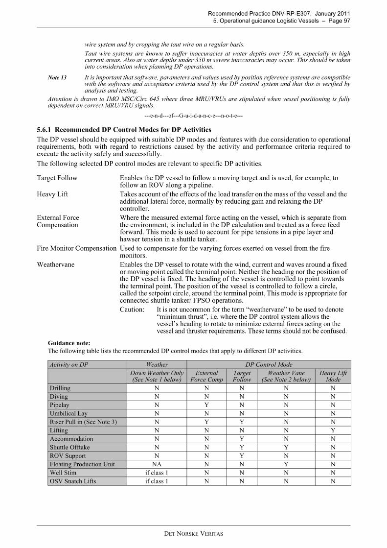
Recommended Practice DNV-RP-E307, January 2011 5. Operational guidance Logistic Vessels – Page 97
wire system and by cropping the taut wire on a regular basis. Taut wire systems are known to suffer inaccuracies at water depths over 350 m, especially in highcurrent areas. Also at water depths under 350 m severe inaccuracies may occur. This should be takeninto consideration when planning DP operations.
Note 13 It is important that software, parameters and values used by position reference systems are compatiblewith the software and acceptance criteria used by the DP control system and that this is verified byanalysis and testing.
Attention is drawn to IMO MSC/Circ 645 where three MRU/VRUs are stipulated when vessel positioning is fullydependent on correct MRU/VRU signals.
---e-n-d---of---G-u-i-d-a-n-c-e---n-o-t-e---
5.6.1 Recommended DP Control Modes for DP ActivitiesThe DP vessel should be equipped with suitable DP modes and features with due consideration to operationalrequirements, both with regard to restrictions caused by the activity and performance criteria required toexecute the activity safely and successfully.The following selected DP control modes are relevant to specific DP activities.
Guidance note:The following table lists the recommended DP control modes that apply to different DP activities.
Target Follow Enables the DP vessel to follow a moving target and is used, for example, to follow an ROV along a pipeline.
Heavy Lift Takes account of the effects of the load transfer on the mass of the vessel and the additional lateral force, normally by reducing gain and relaxing the DP controller.
External Force Compensation
Where the measured external force acting on the vessel, which is separate from the environment, is included in the DP calculation and treated as a force feed forward. This mode is used to account for pipe tensions in a pipe layer and hawser tension in a shuttle tanker.
Fire Monitor Compensation Used to compensate for the varying forces exerted on vessel from the fire monitors.
Weathervane Enables the DP vessel to rotate with the wind, current and waves around a fixed or moving point called the terminal point. Neither the heading nor the position of the DP vessel is fixed. The heading of the vessel is controlled to point towards the terminal point. The position of the vessel is controlled to follow a circle, called the setpoint circle, around the terminal point. This mode is appropriate for connected shuttle tanker/ FPSO operations.Caution: It is not uncommon for the term “weathervane” to be used to denote
“minimum thrust”, i.e. where the DP control system allows the vessel’s heading to rotate to minimize external forces acting on the vessel and thruster requirements. These terms should not be confused.
Activity on DP Weather DP Control ModeDown Weather Only(See Note 1 below)
External Force Comp
Target Follow
Weather Vane(See Note 2 below)
Heavy Lift Mode
Drilling N N N N NDiving N N N N NPipelay N Y N N NUmbilical Lay N N N N NRiser Pull in (See Note 3) N Y Y N NLifting N N N N YAccommodation N N Y N NShuttle Offtake N N Y Y NROV Support N N Y N NFloating Production Unit NA N N Y NWell Stim if class 1 N N N NOSV Snatch Lifts if class 1 N N N N
DET NORSKE VERITAS

Recommended Practice DNV-RP-E307, January 2011 Page 98 – 5. Operational guidance Logistic Vessels
Note 1: The term “down weather” means that the vessel is on that side of the offshore structure where theenvironmental forces, acting on their own, would move the vessel away from the structure. Analternative term is that the vessel is on the “force off” side of the structure.
Note 2: The term “weathervane” has a specific meaning in the DP shuttle tanker industry.Note 3: Heavy lift type issues have been experienced on vessels provided with A frames which have been used
in installation type activities. (e.g.- A frame when used off a logistics type vessel on DP where stiffness“created” during set down operations resulted in instability causing buckling of A Frame.) Thepotential for such instability should be assessed if A Frame is being contemplated for use while vesselis on DP.
Note 4: The vessel specific DP Operations Manual should contain sufficient detail of these operating modesand features.
Note 5: The DPOs are to familiarize themselves with operational constraints/ requirements of these modes andfeatures.
Note 6: A detailed and documented risk assessment should be carried out when it is planned to perform any ofthe above activities without the recommended DP control mode.
Note 7: Where DP Logistics vessels, are carrying project/ construction activities, or engaged in activitiesoutside their normal scope they should do so using the recommended DP control mode. This may meanthat the mode has to be installed in the DP control system.
---e-n-d---of---G-u-i-d-a-n-c-e---n-o-t-e---
5.7 Trials and ChecklistsA range of trials and checklists is to be provided for each DP vessel and implemented as a verification that thevessel’s DP system complies with and, is operated in accordance with, applicable standards and guidelines.This verification process should confirm the failure modes and their effects on the systems and equipmentanalysed in the DP FMEA document (to include the Worst Case Failure) and the vessel’s station keeping abilityfollowing its Worst Case Failure. Owners/ operators should refer to the following list of trials and checklistswhen developing an appropriate regime for their own DP vessels. The list below is a typical list for a DP divesupport vessel.
OSV HAZMAT Transfer no quick disconnect Y N N N N
OSV HAZMAT Transfer with quick disconnect N N N N N
OSV with shaft gens and single stern thruster
Needs to head into weather N N N N
Standby Vessels Y if class 1 N N N N
DP FMEA Proving Trials: A series of tests used to prove expected effects of failure modes found in the FMEA desktop analysis. These tests should also include the testing of interfaces between different vendor systems and equipment. These tests should be conducted immediately following launching of a new build vessel and following modifications, additions, upgrades repairs.
Endurance Trials: (new build/ system modifications class requirement): To prove the operation of the DP system under load conditions for at least 4 hours without significant alarms of the DP system.
Annual DP Trials: A series of tests of fault and failure conditions relevant to the DP System. The tests should be designed to prove system redundancy, as defined in the DP FMEA, system performance and equipment functionality, to validate repairs and preventive maintenance, and test the operation of protection and detection devices and responses so as to demonstrate that the vessel’s DP system remains fit for purpose. Annual DP Trials should be performed at a specific occasion once a year and within 3 months of the anniversary of the previous year’s trials. Annual DP Trials also provide the opportunities for training of the vessel’s crew and enhancement of their knowledge of failure modes and their effects.
Activity on DP Weather DP Control ModeDown Weather Only(See Note 1 below)
External Force Comp
Target Follow
Weather Vane(See Note 2 below)
Heavy Lift Mode
DET NORSKE VERITAS

Recommended Practice DNV-RP-E307, January 2011 5. Operational guidance Logistic Vessels – Page 99
Guidance note:Annual DP Trials It is to be noted that M191, which addresses Annual DP Trials is applicable to MODUs and not all vessels. Text fromM191 is included in this section to draw attention to the purpose of Annual DP Trials.The following guidelines apply to the development and the conduct of Annual DP Trials for a DP MODU inaccordance with guidance contained in IMCA M191. M191 guidance describes a regime of annual testing that isconducted on an incremental basis throughout the year as opportunities arise but needs to be completed within atwelve month period. M191 also recognises the contribution that planned maintenance systems can play in verifyingthe status and performance of certain DP equipment throughout the year.M191 gives the purpose of Annual DP Trials as follow; “...... to improve the DP system safety and performance by testing faults and failure conditions important to DP safetyto prove the ability of the vessel to keep position after single point failures associated with the IMO equipment classand to verify the FMEA requirements. When faults identified during the year on similar DP MOUs are determined tobe feasible on the vessel then additional tests should be incorporated in the trials program.”Using the above quotation as the background, owners/ operators should use the vessel specific DP FMEA andProving Trials as the principal source for developing the Annual DP Trials program.
Note: Experience has shown that, owing to heavy operational demands, DP drilling units are not usually able to meet the above criteria for conducting Annual DP Trials at a specific time once a year. This has been recognized by the industry with publication of specific guidance relating to the conduct of Annual DP Trials for DP MODUs. This is given in IMCA M191, “Guidelines for Annual DP Trials for DP Mobile Offshore Drilling Units”. The guidance sets out a regime of annual testing that is conducted on an incremental basis throughout the year as opportunities arise but needs to be completed within a twelve month period.
DP Mobilization Trials: A series of tests to be carried out at the start of a contract, subject to client requirements, to demonstrate redundancy and functional limitations of the DP system.
DP Field Arrival Trials: A series of checks and tests that confirm satisfactory performance of the DP system and verify the set up mode of operation and DP functions.
DP Location Set Up Checklist:
A series of checks to demonstrate that the vessel is properly set up for the location, in particular the satisfactory performance of the position reference systems.
Pre-Dive Checklist: A series of checks performed prior to commencing diving operations. Main and back up communication tests should be included in this process.
ECR Checklists: A series of checks and tests that verify that the vessel’s set up and configuration of systems and equipment meet the requirements of the necessary mode of operation as determined by the Safest Mode of Operation (SMO) and the DP Class or the Task Appropriate Mode (TAM).
500 m Checks: A series of checks and tests performed before entering the 500 m zone of an asset in which set up mode and functions are verified and confirmed. Approval is then obtained to operate in close proximity to the asset. Main and back up communication tests should be included in this process.
Watch Status/ 6 Hour Checklist:
A series of checks and tests performed by the DPOs to verify and confirm the set up of the DP system prior to taking over the DP watch.
Post DP Incident Trials: Tests performed to ensure that the corrective/ repair measures taken following a DP incident have properly addressed the causes of the incident and that the vessel’s DP system is in a safe and operable condition.
Post DP Modification Trials:
A series of checks and tests that are used to determine the effects of modifications and/ or additions on the DP system and the vessel’s subsequent station keeping performance.
Hardware in the Loop (HIL) tests:
Extensive testing of functionality, failures and performance by using advanced simulation techniques and embedded systems. It can be used in factory acceptance tests, sea trials, annual tests, periodical tests and testing after upgrades.
Note: The nomenclature used for the trials and checklists listed above is based on the guideline document, IMCA M112: “Guidelines for Auditing Vessels with DP Systems”. It is recognized that these trials and checklists could be given other titles.
DET NORSKE VERITAS

Recommended Practice DNV-RP-E307, January 2011 Page 100 – 5. Operational guidance Logistic Vessels
Note: The remainder of this subsection on Annual DP Trials is on hold pending formal publication of IMCAguidance on Annual DP Trials which is under development at the time of preparing this RP. Guidancewill be provided in a subsequent revision of this RP.
DP Mobilization TrialsThese trials should be carried out by the vessel’s crew as part of the mobilizing program prior to the start of a newproject. The tests carried out at these trials are less than are carried out at Annual DP Trials but more than at DPField Arrival Checks. The tests should confirm the vessel’s redundancy concept and station keeping performance afterworst case failure. They should also provide assurance of the integrity of the vessel’s DP system and the vessel’soperational limitations.
DP Field Arrival ChecksThese checks should be carried out on arrival at the field. The purpose of these checks is to ensure satisfactoryoperation of the DP system and should include a full functional check of the operation of all thrusters and powergenerating equipment and systems, auto DP and all control modes. The checks should also ensure that the DP systemis set up properly.
DP Location Set Up ChecklistThese checks should confirm that the vessel is properly set up for the working location and that the performance ofthe position reference systems is satisfactory for that location. These checks should take account of any limitations ofthe position reference systems for that location. These checks should be repeated for each change of location.
ECR ChecklistsThese checks should be carried out by the ER staff and reported to the DPOs prior to start of operations and at fixedperiods during DP operations These checks should be developed from the vessel’s DP FMEA and should confirm thatthe vessel’s systems and equipment are set up and configured for the appropriate operating mode. It is theresponsibility of engine room watch personnel to advise the DPOs, at any time, of any abnormalities in relevantsystems or equipment that may affect DP operations.
500 m ChecksAll vessels should undertake 500 m checks. Only vessels engaged in support activities to remain within the 500 m zone.The 500 m zone is not to be used as a standby location unless required to support a specific activity. Vessel heading to be tested at 500 m checks to ensure that thruster loads are acceptable (i.e. determine whetherthruster loads are within the load limits for ASOG). It is important that the vessel carries out its checks on the sameheading as at the final working location. Depending on the performance and distance limitations of the position reference system(s) in use (e.g. Fanbeam), thevessel heading checks may have to be repeated at an intermediate step between the 500 m line and the workinglocation at, for example, 100 m from the working location, prior to commencing work activity.
Watch Status/ 6 Hour ChecklistThe purpose of these checks is to record the status of the DP system and configuration. The checks should verify thatthe vessel’s station keeping performance at the working location is satisfactory and, in particular, that the positionreference systems are properly set up and operating satisfactorily. No testing is carried out. DPOs should completethe checklist prior to taking over the watch, not during the first few minutes of the watch.
Post Modification/ Upgrade DP Trials It is essential to ensure that any modification, change or upgrade to the DP system is fully tested and that the vessel’sredundancy concept has not been affected. Testing should follow on from a detailed FMEA type analysis of the changewhich should be fully documented. The following example shows the inherent dangers of failing to take proper account of change. In this example theinstallation of a more up to date and faster OS computer resulted in the new computer re-booting too early and failingto “ride through” the brief power interruption that resulted from the activation of a changeover relay. This resultedin the temporary loss of that operator station.
---e-n-d---of---G-u-i-d-a-n-c-e---n-o-t-e---
5.8 DP Operations ManualsA vessel specific DP Operations Manual should be prepared for each DP vessel. The vessel specific DP Operations Manual is the most important operational document in the list of requireddocuments. The requirement for a manual has its origins in IMO MSC/Circ 645 (1994) “Guidelines for Vesselswith Dynamic Positioning Systems”. The IMO Guidelines require a series of checklists, test procedures and DP operating instructions to beincorporated into one manual. Each Classification Society has its own specific requirements for a DP Operations Manual, each with differentrequirements for content. The recommendations set out below address areas that are not necessarily required by class. They are based oncurrent industry practices.
DET NORSKE VERITAS
Recommended Practice DNV-RP-E307, January 2011 5. Operational guidance Logistic Vessels – Page 101
The manual should contain sufficiently detailed instruction and guidance to enable the vessel to be operatedsafely in DP and safely execute its intended activities. This will include a clear statement on the DP philosophyfor the vessel, the organisation, responsibilities and roles of key DP personnel, training and competency,watchkeeping and manning, vessel technical data and layout, vessel DP capabilities, operating limits, operatingmodes, the planning and preparation of DP operations, DP operating procedures, emergency procedures, DPincident handling and alert systems and vessel specific trials and checklists that apply uniquely to the vessel. The manual should specifically address operational interfaces between different vendor systems and equipmentto ensure that they are configured and operated properly. This should include interfaces between systems andequipment that are not part of the DP system but which may affect the DP system, such as EmergencyDisconnect Systems (EDS) on MOUs, tensioner systems on Pipelay vessels, etc.The vessel specific manual may also contain generic content, such as company policies, procedures andstanding orders.The manual should represent the way the vessel is operated in DP. For complicated power systems and/ orthruster configurations, it may be useful provide the operator with a thruster and generator operating strategy(TAGOS) to assist in the decision on what generators and thrusters to use for different circumstances anddifferent equipment availabilities. Guidance on the contents of vessel specific DP Operations Manuals is provided in the following IMCAguidelines, M103, M109, M117 (contingency training) and in class society DP rules.
Guidance note:The provision and development of the manual is the responsibility of the DP vessel owner or manager and should beincorporated in the company’s SMS and, where relevant, developed and managed in accordance with Requirement 7of the ISM Code, which states, as follows;
“The Company should establish procedures for the preparation of plans and instructions, including checklists asappropriate, for key shipboard operations concerning the safety of the ship and the prevention of pollution. Thevarious tasks involved should be defined and assigned to qualified personnel.”
The manual should be a standalone document in hard copy. Owners/ operators at their discretion, may provide thisin an electronic format The manual should be readily accessible to all relevant DP personnel, including the master, DPOs, engineers andelectricians. At least one controlled copy including any updates and, where necessary, appendices should be kept onthe DP navigating bridge. All relevant DP personnel should be given sufficient opportunity to familiarise themselves fully with the document andshould be fully conversant with the sections of the manual that relate to their duties and responsibilities. The manual should address operating issues relating to equipment and systems that are interfaced to the DP system.This will include ESD systems (if installed) where the consequences of an automatic shutdown triggered by an ESDmay result in undesirable consequences. The potential for this adverse situation should be assessed and appropriatepreventative measures put in place. Due consideration should be given to initiating disconnect sequence precedingan ESD resulting in a black out. Detailed procedures are to be developed for operating ESD. Procedures shouldhighlight criteria for initiation and consequences. Owners/ operators may wish to refer to the following guidance when developing the vessel specific DP operations manual;
Section 1 Management of DP Operations (company/ vessel specific)Company/ vessel standing operational policies.Basic principles of DP, functional overview of a DP control system.Vessel specific overview of DP system (vessel overview document).Vessel specific DP philosophy, SMO, ASOG, open/ closed bus-tie configurations, worst case failure,environmental envelopes, vessel DP station keeping capabilities.Related DP guidance and reference documents.
Section 2 DP System Description and Operation (vessel specific)Power generation, distribution, electrical systems, thrusters and propulsion (thruster and generatoroperating strategy, TAGOS).Power management, auxiliary systems, fire and flood.DP control system and automation, DP computers and operator stations and networks, including,operating modes. Position reference systems and sensors; DGNSS/ Hydroacoustic management, taut wires, gyros, VRUs,wind sensors draft sensors, current sensors, etc.Communications systems, internal and external, routine and emergency.If applicable, disconnect systems; auto/ manual emergency shutdown systems (ESD), emergencydisconnect system (EDS), other emergency and alert systems, interfaces with other vendors equipment(e.g. tensioner systems, external force input). (The failure modes of these systems and the potentialeffects on the vessel’s station keeping ability should be addressed in the DP FMEA).
DET NORSKE VERITAS

Recommended Practice DNV-RP-E307, January 2011 Page 102 – 5. Operational guidance Logistic Vessels
Section 3 DP Operations Procedures Procedure for planning DP operations, including environmental criteria, use of DP capability analysisand DP footprints, DP system set up, power and propulsion set up, required levels of redundancy,position reference system planning, integration with activity planning, simultaneous operations, riskassessment.Development of ASOG (Activity specific operating guidelines), requiring input from analysis,simulation studies study, proven blackout recovery times and EDS times (if applicable) anddetermination of red and yellow watch circles. Development of activity specific criteria for normal,advisory, degraded and emergency conditions, ASOG communications and response procedures.emergency DP procedures, including drive off, drift off, force off, fire and/ or explosion, loss of control,severe weather, loss of DP position references, loss of redundancy, black out, collision, squalls, etc.Position reference system deployment, operation and recovery, including hydrophones, acousticarrays, battery procedures, DGPS set up and differential corrections, other PRS procedures.Normal DP marine operations, including voyage, transit and field arrival checklists, Annual DP Trials,mobilisation trials, field arrival checklists, location set up checklists, watchhandover checklists,activity planning and pre-departure checklists, ESD/ EDS trials (where appropriate), 500 m safety zoneoperations, optimum position and heading, position and heading changes, standby time, data logging,offset and turn testing, ROV operations, helicopter operations, operations in strong currents, adverseand heavy weather procedures, special operations.Communications, including routine internal communications, external locations, emergencyprocedures, testing, alert systems, typical communications protocols and messages.DP incident definition, investigation, reporting, close out and record keeping.
Section 4 Organisation and ResponsibilityDP organisation, including onboard organisation, key DP personnel, DP technical and operationalsupport onshore and offshore, manning levels.Duties and responsibilities of key personnel involved in DP operations, examples, master, DPOs, chiefengineer, engineers, electrical officers, ETOs, construction superintendent (If applicable), etc.Onboard watch routines, watchkeeping duties, DP desk procedures, DP handover procedures, DP logkeeping and documentation, including weather log, beacon log, DP standing orders, bridge and engineroom, work/ activity control rooms. DP training, familiarisation and competency assessment, including onboard programs and experiencelevels, skills development, emergency training, drills and exercisesDP reporting and record keeping, including daily reporting, monthly DP status report, tests and trialsreporting, DP incidents and equipment failure reports, vendor reports, DP correspondence, reportingmatrix, etc.Operator Intervention Appendix.
---e-n-d---of---G-u-i-d-a-n-c-e---n-o-t-e---
5.9 Activity Operational PlanningIn recognizing that exposure to risks manifests itself during vessel operations it is recommended that activitiesperformed by DP vessels should be subject to planning and preparation. In planning and preparing for theactivities the following should be considered and, where appropriate, documented:
— Configuration for the Safest Mode of Operation (SMO) or, where appropriate, the Task Appropriate Mode (TAM).— Preparation of the Activity Specific Operating Guideline (ASOG), including onboard discussion with all
relevant stakeholders as part of the pre-project execution/ activity. — Discussion to be included in pre-project execution readiness checklist. — Capabilities of the vessel, both intact and residual capability, following Worst Case Failure (WCF).— Limitations imposed by water depth.— Consequences of a loss of position and/ or heading.— Limitations imposed upon operations by residual capability.
Guidance note:
— Limitations imposed by orientation of weather relative to vessel (e.g. single stern thrusters and where rudder isused to provide transverse thrusters- head in to weather).
— Limitations in activities to be undertaken due to lack of redundancy or unreliability in relative position referencesensors.(e.g. lifting operations restricted to snatch lifts only and no HAZMAT transfer when supporting floatingfacilities, where structured risk assessments have deemed it necessary to impose this restriction).
— ASOGs for Class 1 vessels should state limitations (e.g. leeside only [if applicable])— ASOGs for logistics vessels may have requirements for DPOs and Master to practice manual control prior to
executing activity as part of field arrival checks. ( e.g. single stern thruster configurations where WCF couldresult in loss of stern thrusters)
— SIMOPS and marine vessel interaction and consequences arising from change of status (Green to Blue, Yellowor Red).
DET NORSKE VERITAS

Recommended Practice DNV-RP-E307, January 2011 5. Operational guidance Logistic Vessels – Page 103
— The activity being performed and the necessary time to terminate to bring vessel to a safe position upon the onsetof failure.
---e-n-d---of---G-u-i-d-a-n-c-e---n-o-t-e---
Activities should include day to day operations, any specific operation relevant to the design of the vessel, aswell as any unique operations the vessel is called upon to perform.Appropriate measures should be in place to clearly identify critical tasks/ operational phases of the activity andto ensure that the vessel is set up in Safest Mode of Operation and operating within post WCF capability. Wherea decision has been made to operate in a TAM a separate ASOG covering TAM should be produced.
Note: The ASOG should be developed by extracting all the relevant information from detailed technicalreview of the vessel’s DP FMEA, operational manuals and project specific procedures. TheASOG should be validated on board. On a DP MOU, ASOGs are known as WSOGs. Some owners refer to it as WSOC (Well SpecificOperating Criteria).
Guidance note:Safest Mode of Operation (SMO)Any DP vessel, including DP Class 2 and 3, can have the redundancy concept defeated if its systems and equipmentare not configured or operated in the correct way. The SMO sets out the required equipment configurations andoperational standards necessary for the vessel to meet its maximum level of redundancy, functionality and operationand so that no single failure will exceed worst case failure. Every DP vessel has a unique safest mode of operationwhich must be determined from a detailed understanding of the vessel’s DP FMEA and its operationalcharacteristics. The SMO should be the default operational mode for a DP vessel i.e. such that any other operationalmode would be of a lesser standard than the SMO.A detailed review of the DP FMEA is done with a view to identify safest mode. It is suggested that the results of thisreview are summarised in a vessel overview document. This overview document in conjunction with SMO, ASOG,TAGOS could be useful tool to onboard new personnel involved in operations. The ASOG should be accompanied bya single line drawing (SLD) of the power generation, distribution and propulsion system. Logistics vessels, should operate in the SMO when within the 500 m zone.
Task Appropriate Mode (TAM)A Task Appropriate Mode is a risk based mode that the DP vessel may be set up and operated in, accepting that asingle failure could result in exceeding worst case failure and could, result in blackout or loss of position. A taskappropriate mode is consciously entered into following a structured assessment of the risks of the operation to beundertaken by the vessel. It may be appropriate in situations where it is determined by risk assessment that theconsequences of a loss of position are considered to be low enough to permit a lesser standard of DP redundancy,where a loss of position will not result in damage to people or hardware, including the vessel or the environment. Fordiesel electric vessels the TAM may mean operating with closed bus, whereas SMO may require open bus.
Example 1: A DP MOU may operate in this mode during times when Time to Terminate is short, and in Safest Mode,when Time to Terminate is long.
Example 2: A DP pipelay vessel may operate in this mode when more than 500 m from a surface or mission criticalsubsea asset, and in Safest Mode when inside 500 m.
Caution: Logistics vessels should not operate in TAM when within the 500 m zone.
Activity Specific Operating Guidelines (ASOG)The ASOG differs from the SMO and TAM in that it relates specifically to a known location and activity. The ASOGperforms the same function as Well Specific Operating Guidelines (WSOG), which relate to drilling activities. Inaddition the ASOG differs from the SMO and TAM in that the ASOG sets the operational, environmental andequipment performance limits for the DP vessel in relation to the specific activity that it is undertaking, whereas theSMO and TAM may not be location specific. An ASOG should be developed for every activity and location.
Summary: A DP vessel should be set up in accordance with its SMO unless it is determined by risk assessment that thelesser standard, TAM, is appropriate (not recommended within the 500 m zone). In addition, ASOG shouldbe developed and implemented by a DP vessel for every activity (location specific) that it carries out.
Note: The vessel owns the SMO and ASOG document and the process that is used to develop it, from inceptionthrough to implementation.
Refer to Sec.5.21 for an example of an SMO and ASOG for a DP Logistics Vessel.The SMO is presented in a tabulated format and shows two conditions (GREEN – NORMAL) and (BLUE –
DET NORSKE VERITAS

Recommended Practice DNV-RP-E307, January 2011 Page 104 – 5. Operational guidance Logistic Vessels
ADVISORY) for each item, as follows;
The SMO goes beyond equipment set up. It also defines operational standards. Typical items contained in the SMOwill include the following;
— Power plant set up, including whether operating open or closed bus— Diesel generators, including confirmation of 100% output in DP— Thrusters, including confirmation of 100% output in DP— Power management, including configuration, confirmation that auto stop is off, black start enabled— Uninterruptible power supplies (UPS), including confirmation of power supply, functional testing, no cross
connections— Manual controls and independent joystick, including confirmation of readiness and testing— DP control system, including consequence analysis, mode availability and selection— Position reference systems, including availability, testing and selection, absolute and relative systems, placement
of targets for DP OSVs— Set speed of rotation and speed of moves, suggest 10 deg/min and 0.3 m/sec, respectively — Sensors, including availability, testing and selection— Fuel systems, including confirm redundancy, tank levels, standby starts, isolations, crossovers— Sea water cooling, including confirm redundancy, standby starts, isolations, crossovers— Fresh water cooling, including confirm redundancy, standby starts, isolations, crossovers— Compressed air, including confirm redundancy, safest compressor operating mode— DP and ER manning, including watchkeeping rotas, qualifications and competency of watchkeepers— Trials and checklists — ESD status (if applicable)
The ASOG is presented in a tabulated format and shows four conditions (GREEN – NORMAL), (BLUE –ADVISORY), (YELLOW – REDUCED) and (RED – EMERGENCY), as follows;
An ASOG for a DP logistics vessel will typically cover the following items;
— Weather forecast and environmental conditions, including wind speed limits, current speed limits, wave heightlimits
— Vessel positioning performance (weather related), including position and heading excursions — Drive off, drift off scenarios — Diesel generators, including minimum number required for the activity, performance limits and failures
(TAGOS)— Diesel generator loads (TAGOS)
SAFEST MODE OF OPERATION – OUTLINEGREEN BLUE
Definition Normal operations – all systems and equipment fully operational, DP verification processes completed and DP set up confirmed.
Advisory status – where any of the GREEN conditions are not met.
Response For DP operations to commence and continue the conditions in the GREEN column must be met.
Conduct risk assessment to determine whether to continue, change position or cease operations.
ACTIVITY SPECIFIC OPERATING GUIDELINES – OUTLINEGREEN BLUE YELLOW RED
Definition
Normal operations – all systems fully functional and operating within acceptable performance limits.
Advisory status – approaching performance limits or reportable alarm status. Operations may continue whilst risks are being assessed. A failure has occurred that does not affect DP redundancy.
Reduced status – Pre-defined performance limits reached, component or system failure resulting in loss of redundancy. The vessel maintains position although the vessel has lost its redundancy.
Emergency status – pre-defined operational or performance limits exceeded, component or system failure resulting in loss of control or position.
Response
For DP operations to commence and continue the conditions in the GREEN column must be met.
Conduct risk assessment to determine whether to continue, change position or cease operations.
Stop operations and initiate contingency procedures with a view to reducing the time to terminate. Prepare to disconnect.The operation should not be resumed before the vessel has regained redundancy or before all risks have been fully assessed to determine whether it is acceptable to resume operations with compromised redundancy.
Abandon operations. Take immediate action, i.e. initiate EDS (disconnect sequence) to ensure the safety of people, the environment, the operation and the vessel.The vessel should be moved to a safe position. No DP operation is to be recommenced until a full investigation has been implemented, failure resolved and fully tested.
DET NORSKE VERITAS

Recommended Practice DNV-RP-E307, January 2011 5. Operational guidance Logistic Vessels – Page 105
— Thrusters, minimum number required for the activity, performance limits and failures (TAGOS)— Thruster loads (TAGOS)— Phase back conditions (eg. thruster phase back, DP control system power limiting) — Battery and UPS systems — PMS and VMS status and operation — Auxiliary systems, including fuel, SW and FW cooling, air – performance limits and failures— Uninterruptible power supplies (UPS), including operation, charger output and supply status, failures— DP control system, including operation and performance of DP controllers and OS, failures— DP control system displays, including mimics, performance and failures— DP networks, including operation and redundancy, failures— Position reference systems, including number of enabled systems and performance, failures— Sensors, including number of enabled systems, performance and criticality to activity, failures— Critical communications, including onboard systems, performance and failures — Non essential DP systems, including ventilation and a/c – performance and failures— Fire, flood, visibility, collision, including threat to safety of the DP operation — Simultaneous operations, including communications with assets.
---e-n-d---of---G-u-i-d-a-n-c-e---n-o-t-e---
5.10 CommunicationsThe vessel should be equipped with the appropriate primary and secondary equipment needed to communicatebetween all parties (stakeholders) whilst carrying out the intended task.Effective internal and external communications is a key tool to manage risk.Communications in this context include voice, visual (lights/ displays) and audible means (alarms). Means ofcommunication are not limited to the above but include integrated IT systems using wireless networktechnology that combine communications with other features, including AIS and DGNSS. Operational specific visual and voice communications should ensure that the pertinent information flowsbetween the key operating points as well as to and from assets and/ or other vessels that might be affected bythe operation being carried out. These operating points may be onboard the vessel as well as on other facilities involved with the activity.Communication protocols are to be set up to provide pertinent information regarding intent, current status ofplanned as well as unexpected events during the execution of the activity. Continuity of communications during foreseeable emergency situations should be taken into account. Communications should be taken into account when detailing the roles and responsibilities of key personnelduring the planning stages for the intended task, ensuring that a common working language and terminology isused at all times. Guidance on communications is provided in M103, M182 and M205.
Note: The importance of communication to be emphasized by incorporating into the ASOG.
Guidance note:There should be redundant voice communications systems to all key locations on board the DPO vessel. At least oneof the systems should be hands free. The DPO should have a view or CCTV coverage of all important operationalareas onboard as well as of important points of interest external to the vessel. Communications and alarm systems should be protected against power supply failure. Battery/ UPS back up powersupplies are recommended.Some modern communications and alarm systems rely solely on software activated alarms through the network. Thissole dependency is not recommended. Manual activation of alarms should never be overlooked in design or inoperation.Communications and alarm systems for all DP related equipment and systems and other equipment and systems notdirectly related to DP, but which will have an effect on DP, should be located close to the DP control station. Thisshould include fire zone alarms systems. Simultaneous operations (SIMOPS) depend on effective communications between all vessels and units involved in theoperation. It is important that change of status between vessels and units engaged in SIMOPs is communicatedspeedily and reliably. It should be noted that developments in sensor and communications technologies are underwayto relay, among other things, change of vessel or unit SMO or ASOG status. With these systems any change of statusfrom GREEN to BLUE, YELLOW or RED will be instantaneously relayed to all vessels and units engaged in SIMOPs.These technologies are expected to deliver and aid in the management of complex SIMOPS.
---e-n-d---of---G-u-i-d-a-n-c-e---n-o-t-e---
5.11 DP Planned MaintenanceDP vessels should have a structured planned maintenance system that specifically addresses maintenance ofthe vessel’s DP system, equipment and support systems. Relevant guidance is given in IMCA M109.Planned maintenance should address all equipment that has an impact on the vessel’s station keeping
DET NORSKE VERITAS

Recommended Practice DNV-RP-E307, January 2011 Page 106 – 5. Operational guidance Logistic Vessels
capabilities. This should include indirect components such as generator circuit breakers, bus tie breakers, etc.Maintenance should include regular cleaning, calibration, and testing of equipment as outlined inmanufacturer’s recommendations and industry guidelines.Records of planned and unplanned maintenance should be kept in an auditable format, either hard copy orappropriate electronic format. These records should include vendor service records as well as maintenanceperformed by vessel personnel. These records should be kept on board for the period specified by the owner/operator. A minimum number of required critical DP spares should be maintained on board. The critical spare inventoryshould be monitored via a formal inventory program that is closely linked to the planned maintenance system.This should assist in getting back to normal operating condition after equipment failure or DP incident.
Note: The client’s due diligence process is usually the main driver in the critical path to return to normaloperating condition. Typically, this also involves vendor support as well as the client’s DP consultant.
Note: Maintenance on DP related equipment whilst conducting DP operations should be controlled bya documented permit to work system and should always take into consideration the potentialalteration of failure modes and increased criticality of failure consequences on DP capabilitiesand/ or redundancy.
Note: System upgrades and changes (hardware and software) are typically subject to class approval. Inaddition, parts replaced during maintenance may require certification by class.
Guidance note:It should be recognised that DP vessels, may from time to time require that certain items of equipment are temporarilytaken out of service for the purposes of essential planned maintenance. Where thrusters and/ or generators aretemporarily taken out of service this is likely to have an impact on the vessel’s DP capability and its worst case failure.In preparation for these occasions it is recommended that a thruster and generator operating strategy (TAGOS) isdeveloped to take account of the impact on DP capability and/ or worst case failure. If the impact on DP capabilityand/ or worst case failure is significant, it is suggested that additional DP capability plots correlated to the TAGOSbe provided on the vessel. It is recognised that deferring scheduled planned maintenance due to work activities increases the potential forfailures. Vessel operational teams are encouraged to incorporate planned maintenance as a guideword in HIRAs(Hazard Identification and Risk Assessments).Making DP critical equipment unavailable while within the 500 m zone in order to carry out preventive maintenanceshould be avoided.
Note: The potential for common mode failures increases where same vendor equipment of same type and ageare installed and in operation. (Example experienced - simultaneous failure of three wind sensors ofsimilar type and hours of service (“ageing”) accompanied by mechanical stressing (gusts experiencedduring a hurricane event that was in proximity of the rig).
---e-n-d---of---G-u-i-d-a-n-c-e---n-o-t-e---
5.12 DP IncidentsDP vessels should be provided with and operate appropriate DP incident reporting, investigation and closingout procedures. This should be in accordance with vessel owner or operators’ and, if applicable, clients’processes. Documented records should be kept and be capable of auditing. Where SMO, TAM and ASOG are used as tools to manage DP operations a suggested approach is that, apartfrom the exceptions in the notes below, any reactive change of DP status from GREEN to YELLOW or REDshould be regarded as a DP incident, and should be reported, recorded and investigated.
Note: A change of status triggered by prearranged agreement between the Master, and senior onboarddecision makers, allowing the vessel to exceed environmental limits should not be regarded as aDP incident.
Note: An operator initiated change of status as a result of a conscious decision based on risk analysis of thecircumstances where the trigger points have not been reached should not be regarded as a DP incident.
It is recommended that reactive YELLOW and RED DP incidents are investigated as soon as practicable afterthe DP incident and, where relevant, trials are carried out as part of the investigation process. The purpose of the investigation and the trials should be;
— to assist in identifying the root causes of the incident— to verify and validate that measures to address the root cause are effective— to validate that effective measures have not introduced any additional potential to cause failures (both
hidden and apparent).
In the event of the occurrence of a DP incident relating to the vessel’s configuration as described in the DPFMEA and other documents, it is suggested that the FMEA provider is involved in the incident investigation.This will facilitate lessons learnt to be implemented into the DP FMEA and proving trials program. Owners/ operators of DP vessels are encouraged to share lessons learned from DP incidents with the wider DP
DET NORSKE VERITAS

Recommended Practice DNV-RP-E307, January 2011 5. Operational guidance Logistic Vessels – Page 107
community. DP systems and equipment vendors are also encouraged to do likewise and to share informationon unexpected faults, features and failures that are identified in operation. IMCA’s station keeping incidentreporting scheme provides a suitable channel for disseminating relevant information throughout the DP sector.
Guidance note:The IMCA station keeping incident reporting scheme has been in place for many years and annual reports arepublished each year which summarise each reported incident as well as providing an overview of all the incidents forthe year. These annual reports are available to IMCA members and non-members alike. Owners/ operators arerecommended to make these reports available to key DP personnel onboard their vessels so that they can learn fromthe experience of others.The IMCA station keeping incident reporting scheme or other repositories of DP incidents needs the support of thewhole DP community to be an effective learning, sharing and risk mitigating tool. It is acknowledged that there couldbe a reluctance to participate in sharing of incidents for fear of unwanted disclosure of company identification as thesource of the DP incident. Industry bodies who provide repositories for incident reporting are encouraged to provideanonymity and positively communicate this to the DP community. Owners/ operators are encouraged to draw uponlearnings from incidents experienced and avoid recurrence. Vessel operational teams are encouraged to systematically evaluate potential for incidents on their own units basedon published analysed information. Where additional technical support is required to aid this systematic analysis itshould be sought.
---e-n-d---of---G-u-i-d-a-n-c-e---n-o-t-e---
5.13 Reporting and Record KeepingOwners or operators of DP vessels should have an effective reporting and record keeping system. There should be a clear line of reporting DP related items onboard the DP vessel and between each departmentand this should involve key DP personnel. There should also be a clear line of reporting between the DP vesseland the company’s shoreside management. DP related records should be maintained onboard and, whereappropriate, at the company’s premises. The documents and records contained in Sec.5.2.2, should be accessible to key DP personnel and to otherinterested parties.DP vessels, on occasion, carry out activities which may be unique to project requirements. Records of theseactivities including pertinent information from Hazards and Risk Identification (HIRAs) should be made andkept onboard for future reference, both for training and familiarisation processes as well as for reference in caseof similar project requirements in the future.
Guidance note:The following records should be kept and made accessible to vessel crew and to other interested parties:
— DP FMEA & FMEA Proving Trials reports— Annual DP Trials— DP checklists for bridge and engine room— DP incident investigations & close out reports (see Note 1 below)— DP system faults, repairs, modifications and upgrades (see Note 2 below)— Vessel specific familiarisation and training for short service employees involved in DP operations and ongoing
training and development programs for experienced DP personnel— Operational logs & DP alarm print outs— DP data logging records (if applicable)— DP system equipment vendor reports — DP Footprint Plots— Vessel overview documents, SMO and ASOGs, TAGOS.
DP vessels, on occasion, carry out activities which may be unique to project requirements. Effective record keeping of such activities has the following benefits:
— assists in identifying best practices — demonstrates the vessel’s performance— facilitates knowledge capture and transfer — assists in identifying or justifying equipment improvements.
Guidance on reporting and record keeping is provided in M109, M163
Note 1: Owners/ operators should recognise the benefits that electronic DP data logging systems offer whencarrying out DP incident investigations and establishing root cause.
Note 2: Documentation relating to modifications and upgrades should be kept and available for reference. This willinclude risk analysis of the interfaces and documentation and records of all commissioning and testing.
---e-n-d---of---G-u-i-d-a-n-c-e---n-o-t-e---
DET NORSKE VERITAS

Recommended Practice DNV-RP-E307, January 2011 Page 108 – 5. Operational guidance Logistic Vessels
5.14 CompetenceDefinition: Competence is the acquisition of knowledge, skills and abilities at a level of expertise sufficient
to be able to perform in an appropriate work setting.DP vessel owners/ operators should operate a structured competence assurance program that is applied to allkey DP personnel with special focus on ensuring vessel and task specific competence. Guidance is provided in M103, M117 (IMO738)Vessel specific competency should, as a minimum, be demonstrated in the following areas:
— Operational modes— DP FMEA familiarization— DP Operations Manual familiarization— Project/ activity requirements— Contingency plans, modes and drills.
Guidance note:Key DP personnel include masters, DPOs, engineers, electricians, electronic technicians and anyone involved in thesafe position keeping capabilities of the vessel and includes those involved in the deployment of PRSs. Owners/operators are encouraged to develop their own competency verification processes for all key DP personnel. IMCA M117 provides the DP sector with detailed guidance on the training and experience of key DP personnel. M117has been adopted by the IMO and issued as IMO MSC/Circ 738 (1996). A reference to M117 is also made in theMODU Code. M117 provides guidance on formal training courses for DPOs and other key DP personnel, including watchkeepingmarine engineers and electronic maintenance staff. M117 recognises the formal training and certification scheme forDPOs administered by the Nautical Institute. The Nautical Institute scheme is universally recognised as the industrystandard for formal training and certification of DPOs. The Nautical Institute DPO certificate scheme is made up of a combination of formal DP induction and DP simulator(advanced) and onboard supervised watchkeeping experience. There are two levels of DPO certification;
— Unlimited DPO certificate (minimum requirement for DPO on DP Class 2 or DP Class 3 vessels)— Limited DPO certificate (minimum requirement for DPO for DP Class 1 vessels).
DPO certification is only one part of the competency assurance process for DPOs. Such certification is not to beconstrued as validation of competency. Owners/ operators are recommended to refer to further formal training programs described in M117, comprising thefollowing main features for electrical and engineering officers, where appropriate;
— High voltage (HV) training— Power management system (PMS) training— Fire and gas detection and emergency shutdowns (ESD) training— DP control system manufacturer’s maintenance training.
M117 also provides guidance on structured onboard familiarisation programs for key DP personnel, covering thesteps to take to achieve, maintain and enhance competency in DP operations. Owners/ operators may consider implementing the IMCA Competence Assurance & Assessment scheme (IMCA C002Rev 1, 2003) which provides detailed programs for achieving and assessing the competency of key DP personnel,including vessel masters, DPOs, chief engineers and engineers in charge of a watch.
Note: Owners/ operators should also be aware of and recognise the benefits of formal training andcompetency programs that are currently offered by equipment suppliers, vendors and other bodies thatare in excess of established industry standards, such as the Kongsberg initiative in POWERSIMtraining where DPOs are given training, familiarisation and exposure to a variety of power generationrelated faults and conditions that are known to have occurred on DP diesel electric power generationsystems.
Note: Customised training programs have been developed by industry in response to clients requests.Owners/ operators are encouraged to seek information and selectively adopt appropriate programs fortheir training needs.
---e-n-d---of---G-u-i-d-a-n-c-e---n-o-t-e---
DET NORSKE VERITAS

Recommended Practice DNV-RP-E307, January 2011 5. Operational guidance Logistic Vessels – Page 109
5.15 ManningVessels should comply with the statutory requirements for safe manning. Additionally, for DP operations,manning should be in accordance with the following:DP Bridge Crew
EngineersThere should be sufficient licensed engineers on board for all expected operations. At least one licensed engineer should be available at all times, should be on watch during critical activities andshould have at least 6 months experience on similar equipment and operations. The engineer should be fully cognisant of DP operations, familiar with the vessel’s DP FMEA document andthe effects of failures of equipment relating to the position keeping of the vessel.In DP 2 or 3 operations, the engineer should be familiar with the general philosophy of redundancy as it relatesto split mechanical, electrical and ancillary systems.Electrician/ Electrical EngineerIf required on board, an electrician should have appropriate high voltage training/ certification, if applicable tothe vessel. As with vessel engineers, the electrician/ electrical engineer should have at least 6 monthsexperience on similar equipment and operations.The electrician should likewise be fully cognisant of DP operations, familiar with the vessel’s DP FMEAdocument and the effects of failures of equipment relating to the position keeping of the vessel.
Notes: Where the minimum experience requirements cannot be met a risk based approach should betaken to determine the suitability of personnel and any additional support requirements forintended operations.For low risk operations guidance is provided in IMCA M182. If used, the guidance providedwithin this document should be validated against the risks.
5.16 Intervention – Role of the DPO and EngineerIntroductionThe notes in this section consider the role of the DPO and watchkeeping engineers, specifically addressingoperator intervention in terms of the complexities of the regulatory background (operator interventionspecifically addressed in Class rules) as well as operational practicalities.
Note: The overriding role of the DPO in emergency situations is to stabilise the situation and to takepositive action to prevent escalation.
GeneralRules and guidelines on levels of operator intervention in response to a failure in a DP Class 2 or DP Class 3vessel have changed over the years and different classification societies have chosen to place different levelsof emphasis and different interpretations on these rules. The practical effect of this is that vessels of differentages and different class society can vary significantly in terms of the amount of operator intervention expected,allowed or required. Even in the case of DP Class 1 vessels, levels of redundancy and automation areinfluenced by differences in the main rules for the classification of ships.
Operation Minimum Bridge Crew per shift Minimum ExperienceWhen undertaking critical activities in proximity to surface or sub surface structuresSee Note 1 below
2 unlimited DPOs on the bridge capable of operating the vessel both in DP and manual control. See Note 2 below.
Unlimited DPO with a minimum of 3 years experience in DP operations, at least 6 months of which should have been on the subject or sister vessel. Experience level should be documented and auditable.See Note 3 below
Note 1: Critical activities are those activities where the consequences of equipment failure or loss of position are greater than under normal operating circumstances. For example, critical activities on a DP dive support vessel would include those occasions where the Time to Terminate is long, such as when the diver is inside a welding habitat or where the diver’s worksite is inside the conductor tubes at a production facility.
Note 2: The Master should not be considered as one of the required unlimited DPOs for meeting the manning requirements since operating as such would negative affect the situational awareness required from his side.
Note 3: It is recognized that in practice, given the near term market conditions owners/ operators will be challenged to meet the recommended level of experience for DPOs. Owners/ operators should recognize the associated risk from inexperienced personnel and have plans in place to address them while striving.
DET NORSKE VERITAS

Recommended Practice DNV-RP-E307, January 2011 Page 110 – 5. Operational guidance Logistic Vessels
Examples of the rules and guidelines that have influenced the design of redundancy concepts are given below: Functional Requirements IMO MSC 645 Section 3.1.4 states:
General: “Redundant components and systems should be immediately available and with such capacity thatthe DP-operation can be continued for such a period that the work in progress can be terminatedsafely. The transfer to redundant components or systems should be automatic as far as possibleand operator intervention should be kept to a minimum. The transfer should be smooth and withinacceptable limitations of the operation.”
DNV rules for the classification of Ships Pt.6 Ch.7 Sec.2 states:
Redundancy: “The DP-system shall be designed with redundancy. A position keeping ability shall bemaintained without disruption upon any single failure. Full stop of thrusters and subsequentstart-up of available thrusters is not considered an acceptable disruption. Component and system redundancy, in technical design and physical arrangement, should inprinciple be immediately available with the capacity required for the DP-system to safelyterminate the work in progress. The transfer to components or systems designed and arrangedto provide redundancy, should be automatic and operator intervention should be avoided.”
“Redundancy shall be based upon running machinery. Automatic or manual intervention arranged to improvethe position keeping ability after a failure will be accepted. Automatic start of equipment may be accepted ascontributing to redundancy only if their reliability and simplicity of operation is satisfactory so that they canbe brought into operation before position and heading keeping performance is degraded. The redundancy requirements will not be considered as complied with if based upon start or restart ofgenerators and/ or thrusters.”The distinction between ‘improving station keeping capability after a failure’ and ‘contributing to redundancy’should be noted. The latter is intended to mean that the contribution of this equipment or feature can beconsidered when defining the vessel’s post WCF DP capability. The former cannot be considered whendefining this capability thus DP Class 2 and DP Class 3 vessels should not operate in conditions where theywould depend on this equipment to maintain position. However, the feature can be used to improve capability.
Faults requiring operator interventionThe following list comprises known faults and features in DP systems that have been known to require operatorintervention to prevent escalation of the failure effect or loss of position. Prudent watchkeeping practices willdetect the listed events that require operator (DPO/ engineer) intervention,
— A faulty thruster may respond poorly to DP commands giving rise to a speed/ torque or azimuth predictionerror. The DPO should assess the performance of the thruster and shut it down using the emergency stopif necessary.
— Failure of a thruster to full thrust or uncontrolled rotation will require the DPO to shut the thruster downusing the emergency stop. The process of identifying the faulty thruster may be made more difficult by thefact that all thrusters may be operating at high thrust to counteract the effect of the faulty one. Predictionerrors may indicate which thruster is faulty.
— A DP operator station may fail. The DPO must take control at another operator station. Note that positionand heading should be maintained by the DP controller during this time.
— Seawater cooling systems operated from a single sea chest may block giving rise to low seawater pressurealarms requiring the engineers to transfer to the other sea chest.
— Some vessels have no automation for starting redundant pumps and engineers must monitor the conditionof the plant and intervene following an unexpected stop.
— A heat exchanger in a common freshwater cooling system may become fouled requiring the engineers tochange over to another cooler. This condition may be indicated by high freshwater temperature alarms.
— In some diesel electric designs, failures of fuel control systems or generator excitation systems candestabilise the entire plant if the vessel is operated with a common power system (busties closed). In suchcircumstances the engineers may open the bustie in an attempt to isolate the fault to one side or the other.A load sharing imbalance alarm may assist in identifying the onset of the fault. Note that in somecircumstances the fault may escalate at a rate which precludes effective operator intervention and blackoutmay result.
— A distribution system supplying a DP UPS may fail. The ‘on-batteries’ alarm will indicate to the DPO thatcertain important DP control system consumers may be lost. The DPO or ET can review the UPSdistribution list against sensors, reference systems and operator stations in use to determine whether anyconfiguration changes should be made, for example selecting the other DP controller or OS before theonline controller or OS fails.
— On some DP vessels with a single stern tunnel thruster and two main propellers which depend on therudders to provide redundant athwartships thrust it may be necessary to transfer the tunnel thruster to theother power distribution system and restart it in the event that the distribution system supplying one mainprop and the stern tunnel thruster fails.
DET NORSKE VERITAS

Recommended Practice DNV-RP-E307, January 2011 5. Operational guidance Logistic Vessels – Page 111
— On a DP Class 3 vessel, loss of the main DP station will require the DPO to take control at the backup DPstation.
— On a DP Class 2 vessel loss of both DP control systems will require the DPO to take manual control of thevessel at the independent joystick or manual control levers. On a DP Class 1 vessel loss of DP controlsystem will require the DPO to take manual control of the vessel at the independent joystick or manualcontrol levers
— On vessels with two wind sensors a difference alarm may require the DPO to make an assessment of whichwind sensor to use. In the case that one of the wind sensors has failed to ‘high wind speed’ it may benecessary to rapidly deselect the faulty wind sensor before it initiates a drive off depending on the type ofDP control system.
— On vessels with only two gyro compasses a difference alarm may require the DPO to make an assessmentof which gyro to use. A faulty gyro may cause a rapid change of heading if not deselected promptly.
— On vessels with two MRUs a difference alarm may require the DPO to make an assessment of which MRUto use.
— DP control systems employ a range of protective functions designed to reject an errant position referencesystem. Class rules require that three references are in use for DP Class 2 & 3 vessels and two of the threeshould be based on different principles of measurement. This provides a large degree of protection againsta drive off related to a position calculation error but such incidents do occur and DPOs can be expectedto determine which reference systems are responsible and deselect them.
— On vessels with a common fuel supply system, which can be found even on some DP Class 2 vessels, it maybe necessary to change over a fuel filter or isolate a leak to prevent all generators being affected.
— On some vessels with transferable thrusters it may be necessary for the engineers to manually change overauxiliary services for the thruster even if the main supply changes automatically. This changeover, ifrequired, is to prevent the unexpected consequences of failure.
— DPOs should be aware of the thruster and/ or power configuration that is used to activate the ConsequenceAnalysis alarm. It should not be assumed that it is Worst Case Failure. Where it is established that it is notWCF then steps should be taken to ensure that WCF is used as the trigger for a Consequence Analysisalarm.
Measures to reduce the incidence of faults requiring operator interventionThe most effective way to avoid the necessity for operators and engineers to intervene in faults is to design theredundancy concept in such a way that the need for operator intervention is minimised or preferablyeliminated.In general terms, this will often mean adding additional equipment, greater levels of redundancy, automationand increased system segregation to minimise the impact of any failure. Features such as a third wind sensoror a third DP controller allow voting or other protective functions to be used. However, there may be some aspects of DP system design where operator intervention is preferred to any otherform of response. For example, it may not be desirable to automatically transfer control location in responseto a fault. It may be better for the operator to decide where control transfers to by taking control at that station. There is also a risk that poorly designed protective functions will reduce the reliability and availability ofessential equipment such as thrusters and generators. This risk should be considered when applying protectivefunctions to deal with very low probability failure modes.Carefully considering power plant and control system configuration can also reduce the need for operatorintervention. DP Class 2 and 3 vessels should always operate in a redundant/ fault tolerant configuration.Where operator intervention in response to faults is unavoidable then it is extremely important that there areclear and unambiguous alarms and indications to alert the operators to the onset of the fault. It is also of vitalimportance that the required responses to the fault are documented in well-written procedures and practicedso that all DPOs and engineers are familiar with them and can take action in a confident manner.
DET NORSKE VERITAS

Recommended Practice DNV-RP-E307, January 2011 Page 112 – 5. Operational guidance Logistic Vessels
5.17
DP
Foot
prin
t Plo
ts –
Wor
ked
Exa
mpl
es
Figu
re 5
-1Su
pply
Ves
sel –
Wor
ked
Exa
mpl
e 1
DET NORSKE VERITAS

Recommended Practice DNV-RP-E307, January 20115. Operational guidance Logistic Vessels – Page 113
Figu
re 5
-2Su
pply
Ves
sel –
Wor
ked
Exa
mpl
e 2
DET NORSKE VERITAS

Recommended Practice DNV-RP-E307, January 2011 Page 114 – 5. Operational guidance Logistic Vessels
5.18 Annual DP Trials Test Table Blank – DP Logistics Vessel
Guidance note:The blank Annual DP Trials test sheet is on hold pending formal publication of IMCA guidance on Annual DP Trialswhich is under development at the time of preparing this RP. Guidance will be provided in a subsequent revision ofthis RP.
---e-n-d---of---G-u-i-d-a-n-c-e---n-o-t-e---
5.19 Example of SMO and ASOG
Safest Mode of Operation - Name of Logistics Vessel
This setup applies when the vessel is carrying out DP Operations within the 500 m zone of an offshore facility - AFI (agreed for implementation)
Date
Vessel to be set up and stabilized on DP before entering the 500 m zone. Exiting the 500 m zone may be done on joystick, manual or DP.
Condition GREEN ADVISORY YELLOW RED
Notify Master, Chief Engineer, Client Rep (if on board) and Rig/Platform
NO YES YES YES
ActionCONTINUE NORMAL
OPERATIONS
INFORMATIVE / CONSULTATIVE STATUS (RISK ASSESSMENT)
CEASE OPERATIONS AND BE READY TO MOVE OFF, Vessel to
safe position and on Joystick or Manual if
Applicable
CEASE OPERATIONS - LEAVE 500 m Zone
Switchboard Set Up All bus-ties OPEN Any other configuration
SG1, SG2, AG1 & AG2 (Testing)
Tested at 100% on field arrival or within the last
6 months
Not tested to 100% within 6 months or
problems found
SG1, SG2, AG1 & AG2(Set up)
SG1 and SG2 online.AG1 and AG2 standby.
Any other setup, or problems found
Emergency Generator
Selected to auto start and available for
immediate use. Auto start/connect and load
tested prior to arrival on field.
Any other configuration or known deficiencies reducing redundancy
Blackout Drill (Single Fuel System)
Blackout drill conducted for all DPOs and Engineers onboard,
procedures in place
Any DPOs on watch or Engineers not
performed blackout recovery drill in last 6
months
DP Power Supply
All UPS units fully functional, not
operating on bypass and tested onload 24 hrs prior to field arrival
(NOTE: Batteries must be at optimum charge level before entering
500 m).
Any other configuration or known deficiencies
reducing redundancy or endurance. Not tested
for 30 minute endurance prior to field
arrival
24 Vdc Power Systems (Load test)
All fully functional with DC10 & DC20
cross connect breakers open (breaker F3 open
in both panels) plus DC30 and DC40 cross connect breakers open
(breaker F3 open in both panels). 30 min
battery endurance test carried out on DC10, DC20, DC30, DC40, DC50 24 hrs prior to field arrival (NOTE: Batteries must be at
optimum charge level before entering 500 m).
Any other configuration or known deficiencies
reducing redundancy or endurance. Not tested
for 30 minute endurance prior to field
arrival
DET NORSKE VERITAS

Recommended Practice DNV-RP-E307, January 2011 5. Operational guidance Logistic Vessels – Page 115
24 Vdc Power Systems (Battery Chargers)
All on main feed to charger
Any other setup, or problems found
Main Engines (Drive) Operational and tested to 100% at Field Arrival
Engine not capable of 100% command or
problems found
Propellers and Rudders (Configuration)
One pump running on each (SWC, FWC,
Steering Pumps) with standby pumps ready
for operation.
Any other setup or loss of any rudder.
Bow Thrusters 1&2
Thrusters tested to 100% command in both
directions on manual (Fwd&Aft) and DP at
Field arrival.
Thrusters not capable of 100% command or
problems found
Stern Thrusters 1&2
Thrusters tested to 100% command in both
directions on manual (Fwd&Aft) and DP at
Field arrival.
Thrusters not capable of 100% command or
problems found
Thruster/Main Propellers/Rudders manual levers
Tested and fully operational on Field
arrivalAny known deficiencies
Independent JoystickTested and fully
operational on Field arrival
Any known deficiencies or not tested at Field
arrival
Manual Control
Within 24 hours the Captain and each DPO practice holding vessel
on position for 10 minutes.
Not completed
Thrust levels checked to within ASOG level outside the 500 m zone at operational heading
Within Operating limits Above operating limits
Emergency Stops Stops tested from the bridge on Field Arrival
Stops not tested or function not operational
Thrusters, main propellers and rudders
All on line and selected in DP system
Any known deficiencies, problems,
or issues
DP Control SystemConsequence analysis
enabled, no alarms active
Any other setup
DP related maintenance Not being carried out Requested by permit to work
DP Reference SystemMedian Check setup
and enabled, with three references online
Less than three references online, position reference
deviation >3 m
DGPS Both units operational and available Any other set up
DGPS (Configuration) DGPS 1 on IALA, DGPS 2 on WAAS
Any alarms or other setup
DGPS (Line of sight)Field of operation is
clear of possible obstruction by cranes,
superstructure, etc.
Possibility of masking by cranes/structures
Relative Pos ref (Cyscan) Operational Not operational or faulty
NOTE: Only snatch lifts permitted (no hose transfers or heavy lifts).
RIG MOVEMENT (check at 100 m off and during operation)
Footprint or shading not preventing use of
DGPS
Movement or Shading of Rig such that DGPS
cannot be used in conjunction with relative systems
Wind Sensors Both Available Any other setup
Gyros
All three units operational and visual
heading reference available. Alignment
less than 1 degree
Any other setup
Gyros (North Speed Correction)
Auto Speed and Latitude Not enabled Any other setup
DET NORSKE VERITAS

Recommended Practice DNV-RP-E307, January 2011 Page 116 – 5. Operational guidance Logistic Vessels
VRUsBoth VRUs online, no alarms, alignment less
than 1 degreeAny other setup
Radar & TrafficBoth Radars on &
100% operational; & no traffic with conflicting
CPAAny other situation
Communications (Internal & External)
All vessel's hardwired and portable
communications equipment operational.
Loss of any principal item of communications
equipment
Environment: Current, Wind, Existing Weather & Forecast
Reviewed and found within DP Capability
and DP Footprint plots.Any other condition
Position & Heading Alarms
Tested OK; Heading warning and alarm set
at 3 & 5 degrees, respectively; Position warning and alarm set
at 3 & 5 meters, (10&15 ft) respectively.
Any other condition
Escape route (in Degrees TRUE)
Escape route identified and agreed with field
operations
Escape route compromised or that
possibility during time span of planned
operation
Speed of moves inside 500 m zone
From 500 m to 200 m, <= 0.5 m/sec From 200
m to work location <=0.3 m/sec
Any other setting
Thrust Values when exiting 500 m zone onJoystick or manual
200 m < 25% (minimum to safely pull away); 200 m - 500 m <50% (minimum to
safely pull away out of 500 m zone)
Approaching 25% or 50% respectively
Ventilation All fans Running in E/R and Thruster rooms Any Problems found
Air ConditioningAdequate cooling of DP
computer area on Bridge and
Switchboard room.Any known deficiencies
Watertight doors All closed Any open
Engine Room Manning ER Manned ER not Manned
Bow Thruster RoomChecked regularly
every watch for machinery function,
flooding, etc.Not checked
Fuel Systems
Supply and return cross connects closed. Both port and starboard supply and return lines open. Day tanks sludged regularly during watch. Day tanks filled via purifier prior to entering 500 m
Any other set up or level alarm for day tanks. Any sign or potential threat of fuel oil contamination, blockage or supply failure.
Air SystemBoth air compressors fully operational, auto start function tested and reservoirs full
Any other setup
Fresh Water Cooling System
All fresh water cooling systems operational. Standby pump tested prior to arrival on field.
Any other configuration or known deficiencies reducing redundancy
Sea water-cooling systemAll system 100% Operational. Standby pump tested prior to arrival on field.
Seawater temperature alarm
DET NORSKE VERITAS

Recommended Practice DNV-RP-E307, January 2011 5. Operational guidance Logistic Vessels – Page 117
Activity Specific Operating Guidelines - Name of Logistics Vessel
This setup applies when the vessel is carrying out DP Supply Operations within 500 m zone of an offshore facility.
Condition GREEN ADVISORY YELLOW RED
Notify Master, Chief Engineer, Client Rep (if on board) and Rig/Platform
NO YES YES YES
ActionCONTINUE NORMAL
OPERATIONS
INFORMATIVE / CONSULTATIVE STATUS (RISK
ASSESS)
CEASE OPERATIONS AND
BE READY TO MOVE OFF, Vessel to
safe position and on Joystick or Manual if
Applicable
CEASE OPERATIONS - LEAVE 500 m
ZONE IMMEDIATELY
Weather Forecast Within Operating limits
Approaching operating limits
Exceeding operational limits
Checklists: 6H; Watch; 500 m Completed Not completed or abnormalities noted
DRIVE OFF All systems operating correctly
Immediately when recognized by DPO Unable to bring
vessel under control
DRIFT OFF All systems operating correctly
Immediately when recognized by DPO Unable to bring
vessel under controlVessel Footprint/Weather related excursion On position Position limits reach 3 m
(10 ft)Approaching 5 m
(15 ft)
Heading excursion On heading Heading limit reached 3 degrees Approaching 5 degrees
Heading & position control (Thruster load/DP Feedback)
Heading & position control achieved with
<45%Approaching 50% More than 50%
Shaft Generators SG1-2SG1 & SG2 online,
AG1 and AG2 standby. No alarms
Any other setup or Alarms Any generator failure
Shaft Generator Loads Both Generators <45%
Any SG approaching 50%
Either > 50%, or failure of a generator
DP UPSs No UPS in Bypass, no alarm
Any UPS in Bypass or alarm Loss of one DP UPS
24 Vdc SystemAll 24 Vdc active and fully charged No
alarmsAny alarms
Loss of a 24 Vdc system or charger
failure
Main propulsion (drive engines & rudders)
Both enabled, no alarms
Any other set up, any alarms or poor control
Loss of either Port or Stbd
Bow Thrusters available Both enabled, no alarms
Any other set up, any alarms or poor control
Loss of any bow thruster
Stern Thrusters available Both enabled, no alarms
Any other set up, any alarms or poor control
Loss of any stern thruster
Fuel Systems No Alarms
Any sign or potential threat of fuel oil
contamination, supply line blockage, or any other supply failure
Loss of any generator due to fuel oil
contamination, line blockage, or any other
supply failure
DP Control System (Power Mimics)
All displays check and up to date
Any incorrect information
Incorrect information that affects DP
operation
DP Control System (Controllers/OS)
All Controllers and Operator Stations
onlineAny alarms or poor
performanceLoss of one controller
or OS
DP Network Both Networks available, no alarms
Any alarms or poor performance Loss of one network Complete loss of
networks
Position References
All fully operational and verified there is no conflict between relative and absolute
position reference systems due to movement of
reflector, reflective clothing, etc. on the
platform.
Any alarms or poor performance Only one remaining
DET NORSKE VERITAS

Recommended Practice DNV-RP-E307, January 2011 Page 118 – 5. Operational guidance Logistic Vessels
Heading Sensors (Gyro) All three Gyros enabled
Gyro alarms, loss of one gyro Failure of two Gyros
Wind Sensors Both available Mismatch alarm or loss of either wind sensor
Both wind sensors failed and gusty
conditions
VRUs/MRUs Both units available Mismatch alarm or Loss of one unit. Loss of two units.
Loss or problem with any essential Communications (ECR/Deck/Platform)
Redundant Communications One system remaining No communications
Machinery ventilation and Air Conditioning
Operational ventilation and Air
ConditioningAny reduced ventilation
or Air Condition
Reduced ventilation or Air Conditioning resulting in Power
reduction
Starting Air No Alarm Any alarm
Fire No fire or active alarms Any fire alarm Fire Confirmed
Flood No bilge alarms active, no flooding Multiple bilge alarms Flood Confirmed
Visibility Daylight with good visibility Any other condition
Collision (errant vessels)No collision
imminent / minimum approach >500 m
Minimum approach will be < 500 m If collision possible Collision Imminent
SIMOPS – Activity Specific Operating Guidelines - Name of Logistics Vessel
This setup applies when the vessel is undertaking operations in conjunction with an offshore facility
Condition GREEN ADVISORY YELLOW RED
Notify Master, Chief Engineer, Client Rep (if on board) and Rig/Platform
NO YES YES YES
ActionCONTINUE NORMAL
OPERATIONS
INFORMATIVE / CONSULTATIVE STATUS (RISK
ASSESS)
CEASE OPERATIONS AND BE READY TO MOVE OFF, Vessel to
safe position and on Joystick or Manual if
Applicable
CEASE OPERATIONS -
LEAVE 500 m ZONE IMMEDIATELY
Change from Green DP Status of any other vessel in the field Green Advisory Advisory Advisory
Comms/interaction with other vessels
Vessels operating normally with no known problems
Communications problem or Possible
position conflict
No communications or Definite position
conflict
Comms with rig Redundant communications
Communications problem
One communications system remaining
DPO Name Signature
Captain Name Signature
Engineer Name Signature
Chief Engineer Name Signature
Client Name Signature
DET NORSKE VERITAS


