DROPS STANDARD FOR WELLS OPERATIONS
PCSB – WELLS HSE
Document No
WELLS/WHSE/STD/DROPS STANDARD FOR WELLS OPERATIONS/2015/Rev. 0
© 2015 PETROLIAM NASIONAL BERHAD (PETRONAS) All rights reserved. No part of this document may be reproduced,
stored in a retrieval system or transmitted in any form or by any
means (electronic, mechanical, photocopying, recording or
otherwise) without the permission of the copyright owner.
PETRONAS makes no representation or warranty, whether expressed or implied, as to the accuracy or completeness of the
facts presented. PETRONAS disclaims responsibility from any
liability arising out of reliance on the contents of this presentation.
DROPS STANDARD FOR WELLS OPERATIONS
WELLS/WHSE/STD/DROPS STANDARD FOR WELLS OPERATIONS/2015/Rev. 0
May 2015
Page 1-2 of 83
Document Authority

DROPS STANDARD FOR WELLS OPERATIONS
WELLS/WHSE/STD/DROPS STANDARD FOR WELLS OPERATIONS/2015/Rev. 0
May 2015
Page 1-3 of 83
Document Holder / Distribution List
No. Title
Master Wells HSE - Sr. Manager
01 Head, Wells Risk Management
02 Head, Wells Malaysia
03 Head, Wells International
04 Head, Global Wells Technology, Engineering and Support
05 Head, Global Wells Intervention & Services
06 Head, Wells Operations Malaysia
07 Head, Wells Exploration
08 Head, Wells Exploration MPM & PED
Note:
A Document Holder is responsible to communicate and ensure compliance with the
requirements of this document.
Revisions:
The DROPS standard should be reviewed/revised:
1. Once every two years, or
a. After a Major DROPs Accident has occurred in Wells and the learnings
of that incident can justify an immediate revision of the DROPs
standard.
b. Based on the learnings of DROPs incidents in general (frequent analysis
of incidents by Wells HSE).
DROPS STANDARD FOR WELLS OPERATIONS
WELLS/WHSE/STD/DROPS STANDARD FOR WELLS OPERATIONS/2015/Rev. 0
May 2015
Page 1-4 of 83
Amendment Summary
The table below must be completed in detail for each revision. To indicate
amendments from the previous version, vertical lines in the left hand margin shall be added at the amended section.
Rev Page Description Approved By Approval Date
0 Final Draft
1 First Issue
DROPS STANDARD FOR WELLS OPERATIONS
WELLS/WHSE/STD/DROPS STANDARD FOR WELLS OPERATIONS/2015/Rev. 0
May 2015
Page 1-5 of 83
Preface
PETRONAS Policy for Health, Safety and Environment states that:
“PETRONAS shall ensure continual improvement in its Health, Safety and Environment
management and performance, leveraging on people, process and technology.”
This document has been developed to improve uniformity in documentation within PCSB
Wells and achieve consistency in the management of DROPs during Drilling Operations.
The DROPs standard should be used for all PCSB Wells operations and activities.
DROPS STANDARD FOR WELLS OPERATIONS
WELLS/WHSE/STD/DROPS STANDARD FOR WELLS OPERATIONS/2015/Rev. 0
May 2015
Page 1-6 of 83
CONTENTS
1 BRIEF HISTORY OF DROPs 1-10
DOCUMENT REFERENCE. 1-10
2 INTRODUCTION / SCOPE 2-11
3 STATIC AND DYNAMIC DROPPED OBJECTS 3-12
DROPS INCIDENTS 3-13
Method of Verification 3-13
4 DROPS PREVENTION PROGRAMME 4-14
METHOD OF VERIFICATION 4-17
5 DROPS POLICY 5-18
6 DROPS PROCEDURE 6-18
7 DROPS PLAN 7-19
8 DROPS THIRD PARTY INDEPENDENT INSPECTION 8-20
Method of verification 8-20
8.1.1.1 Review survey and inspection program. 8-20
9 INTERNAL RIG INSPECTIONS 9-21
10 DROPS TRAINING 10-21
11 DROPS CAMPAIGNS 11-21
12 DROPS TOOLS 12-22
Method of Verification 12-22
DROPS SHELTERS 12-22
Method of Verification 12-23
WORK AT HEIGHT TOOLS 12-23
Method of verification 12-23
13 SECONDARY RETENTION 13-23
14 RESTRICTED ACCESS AREAS (RED ZONES) 14-26
Basic Requirements 14-26
Designating Area Authorities 14-27
Access Diagrams / Zone Maps 14-27
Access to Restricted Areas 14-28
14.1.4.1 Permission to enter Restricted Areas 14-29
14.1.4.2 Controlling Access to Restricted Areas 14-29
14.1.4.3 Permanent Changes to Restriction Classification 14-30
14.1.4.4 Temporary Changes to Restriction Classification 14-30
Method of Verification 14-30
15 TASK PLANNING 15-31
BEFORE STARTING WORK 15-31
DROPS STANDARD FOR WELLS OPERATIONS
WELLS/WHSE/STD/DROPS STANDARD FOR WELLS OPERATIONS/2015/Rev. 0
May 2015
Page 1-7 of 83
WORKING AT HEIGHT 15-31
TASKS INVOLVING LOADING OF LIFTING 15-31
TASK COMPLETION 15-32
LIFT PLANS 15-32
COLLISION CHECKLIST 15-32
16 TOOLS AND EQUIPMENT 16-34
BARRIERS 16-34
FALL ENERGIE 16-35
FALL FACTOR 16-35
GALVANIC CORROSION 16-36
BOLTED CONNECTIONS 16-37
SPECIAL BOLTS 16-37
Bondura Bolt 16-37
Superbolt / Supernut 16-38
17 Bolted Connections 17-38
NORD-LOCK BOLT SECURING SYSTEM 17-38
SPIRAL LOCK 17-39
CASTLE NUT WITH COTTER PIN 17-39
NYLOC LOCK NUT 17-39
ALL METAL LOCK NUTS 17-40
TAB WASHER / TAB PLATE DIN 93 / 463 17-40
PALNUT 17-40
LOCK-WIRING 17-40
CORRECT USE OF COTTER PIN 17-41
SECURING PINS / SAFETY PINS 17-42
SECURING DEVICES (WIRES, CHAINS AND COUPLINGS) 17-42
CORRECT INSTALLATION OF WIRE CLAMPS 17-43
18 Securing of personnel 18-44
DERRICK EVACUATION EQUIPMENT 18-44
SECURING OF TOOLS AT HEIGHT (<5KG) 18-45
SECURING OF TOOLS AT HEIGHT (5-25KG) 18-45
SECURING OF OTHER PORTABLE EQUIPMENT AT HEIGHT 18-45
TOOL CABINETS FOR WORK AT HEIGHT 18-46
SECURING OF PERMANENTLY ATTACHED EQUIPMENT GRATING 18-46
PIPING AND EQUIPMENT FEED-THROUGHS 18-47
RAILINGS 18-47
TOE BOARDS 18-47
DROPS STANDARD FOR WELLS OPERATIONS
WELLS/WHSE/STD/DROPS STANDARD FOR WELLS OPERATIONS/2015/Rev. 0
May 2015
Page 1-8 of 83
SWING GATES 18-48
LADDERS 18-48
FLOODLIGHTS 18-49
LIGHTING FIXTURES 18-49
SC NAVIGATION LIGHTS 18-50
CCTV CAMERAS 18-50
LOUDSPEAKERS 18-52
JUNCTION BOXES AND CABINETS INSTALLED AT HEIGHT 18-52
CABLE TRAYS AND CABLE LADDERS 18-52
WIND WALLS 18-53
SIGNS 18-53
VALVE HANDLES AND VALVE WHEELS INSTALLED AT HEIGHT 18-54
LOCKS ON INSULATION CLADDING 18-54
TEMPORARY / PERMANENT STORAGE OF GAS CYLINDERS 18-55
SNATCH BLOCKS 18-56
UMBILICAL ROLLER SHEAVES (BANANA SHEAVES) 18-56
LOOP HOSES 18-57
LOAD CARRIER UNITS (LCU) 18-58
CORRECT USE OF SHACKLES 18-59
CORRECT USE OF EYE-BOLTS / EYE-NUTS 18-60
19 Storage Area 19-61
RACKS AND STORAGE 19-61
UNNECESSARY EQUIPMENT AT HEIGHT 19-62
SECURING OF PARTS, EQUIPMENT AND MATERIAL DURING WORK AT HEIGHT 19-62
POST INSPECTION / FINAL CHECK OF THE WORK SITE 19-62
OBSERVATION TECHNIQUE 19-63
20 APPENDICES 20-64
DROPS PREVENTION PROGRAMME FLOWCHART 20-64
DERRICK INSPECTION GUIDE CONTENTS 20-65
WEEKLY DERRICK INSPECTION: AREA 3 – TRAVELLING EQUIPMENT 20-68
WEEKLY DERRICK INSPECTION: AREA 4 – DRILL FLOOR & MEZZANINE DECK 20-70
WEEKLY DERRICK INSPECTION: AREA 5 – BOP DECK & LOWER SUBSTRUCTURE 20-74
DROPS PRE-TASK CHECKLIST 20-75
EXAMPLE OF DRILLER’S COLLISION CHECKLIST 20-76
EXAMPLE OF CRANE OPERATOR’S COLLISION CHECKLIST 20-77
EXAMPLE LIFT PLAN TEMPLATE 20-78
EXAMPLE PACKING AND HANDLING CHECKLIST 20-80

DROPS STANDARD FOR WELLS OPERATIONS
WELLS/WHSE/STD/DROPS STANDARD FOR WELLS OPERATIONS/2015/Rev. 0
May 2015
Page 1-9 of 83
GLOSSARY OF TERMS AND ABBREVIATIONS 20-82

DROPS STANDARD FOR WELLS OPERATIONS
WELLS/WHSE/STD/DROPS STANDARD FOR WELLS OPERATIONS/2015/Rev. 0
May 2015
Page 1-10 of 83
1 BRIEF HISTORY OF DROPs
In 1997 as part of a UK Oil and Gas safety initiative known as “Step Change in Safety”, studies were made into key areas requiring improvement in our Industry.
Among the raft of focus areas identified was that of dropped object prevention. To look into the subject, a small workgroup was formed comprising several operators
(BP, Shell, ExxonMobil etc.) and several drilling contractors (KCA Deutag, GSF etc.).
The group identified the drilling sector and in particular the derrick as the source of most dropped object incidents. They recognized that the problem was huge and not
restricted to the UK. Feeling restricted under the “Step Change in Safety” banner, they agreed to establish an independent workgroup and they sought assistance with
the implementation and facilitation of the new international workgroup DROPs Document Objectives
Document reference.
The following documents have been used for the development of the DROPs
Standard.
Document Number Title
DROPs Guidelines DROPS online
DROPs Guidelines IADC DROPs

DROPS STANDARD FOR WELLS OPERATIONS
WELLS/WHSE/STD/DROPS STANDARD FOR WELLS OPERATIONS/2015/Rev. 0
May 2015
Page 1-11 of 83
2 INTRODUCTION / SCOPE
This PCSB DROPS Standard describes the minimum requirements to be met by all facilities assigned to / or operated by PCSB. The unit Owner and/or Operator may
opt to deviate from this Standard, only if it can be sufficiently and satisfactorily demonstrated that by doing so, these minimum requirements are exceeded.
This DROPs standard outlines the specific implementation of the PETRONAS CARIGALI SDN BHD (PCSB) activities carried out that involves organizations with different management systems. As a result, the potential hazards arising through
lack of clarity in certain areas will be addressed under the following elements of this DROPs Standard:
The purpose of this Standard is intended to help eliminate the risk of dropped objects. It applies both to equipment procurement and to equipment already in use in/on your own and hired installations. In many cases, the functional requirements
that are established for the equipment in this document will set a new standard for our activities. The definition of barriers that prevent dropped objects, deployed in
the procurement, use and maintenance of equipment, has been an important goal. When procuring new equipment, it must endeavored to use integrated solutions in respect to barriers. In order to minimize the danger of collision, we must always
evaluate the risk associated with the chosen location of equipment. Equipment must be designed and installed to provide the safest possible access for maintenance. The
functional requirements set forth in this standard must be complied within the whole value chain:
- Design - procurement - installation - operation – maintenance.
By complying with these requirements you will help achieve the goal of zero dropped objects.
DROPS STANDARD FOR WELLS OPERATIONS
WELLS/WHSE/STD/DROPS STANDARD FOR WELLS OPERATIONS/2015/Rev. 0
May 2015
Page 1-12 of 83
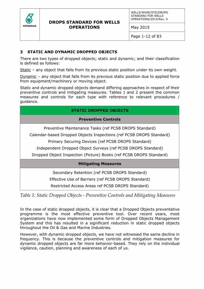
3 STATIC AND DYNAMIC DROPPED OBJECTS
There are two types of dropped objects; static and dynamic; and their classification is defined as follows:
Static – any object that falls from its previous static position under its own weight.
Dynamic – any object that falls from its previous static position due to applied force
from equipment/machinery or moving object.
Static and dynamic dropped objects demand differing approaches in respect of their preventive controls and mitigating measures. Tables 1 and 2 present the common
measures and controls for each type with reference to relevant procedures / guidance.
STATIC DROPPED OBJECTS
Preventive Controls
Preventive Maintenance Tasks (ref PCSB DROPS Standard)
Calendar-based Dropped Objects Inspections (ref PCSB DROPS Standard)
Primary Securing Devices (ref PCSB DROPS Standard)
Independent Dropped Object Surveys (ref PCSB DROPS Standard)
Dropped Object Inspection (Picture) Books (ref PCSB DROPS Standard)
Mitigating Measures
Secondary Retention (ref PCSB DROPS Standard)
Effective Use of Barriers (ref PCSB DROPS Standard)
Restricted Access Areas ref PCSB DROPS Standard)
Table 1: Static Dropped Objects - Preventive Controls and Mitigating Measures
In the case of static dropped objects, it is clear that a Dropped Objects preventative programme is the most effective preventive tool. Over recent years, most
organizations have now implemented some form of Dropped Objects Management System and this has resulted in a significant reduction in static dropped objects
throughout the Oil & Gas and Marine Industries.
However, with dynamic dropped objects, we have not witnessed the same decline in
frequency. This is because the preventive controls and mitigation measures for dynamic dropped objects are far more behavior-based. They rely on the individual vigilance, caution, planning and awareness of each of us.
DROPS STANDARD FOR WELLS OPERATIONS
WELLS/WHSE/STD/DROPS STANDARD FOR WELLS OPERATIONS/2015/Rev. 0
May 2015
Page 1-13 of 83
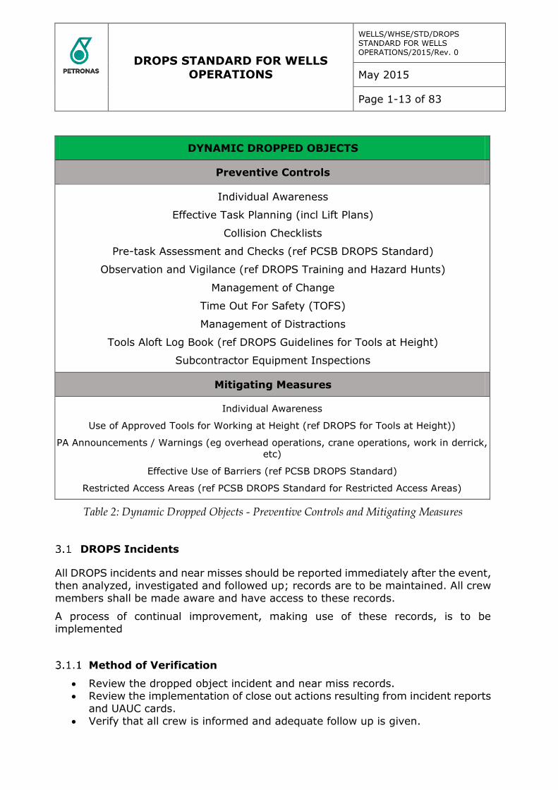
DYNAMIC DROPPED OBJECTS
Preventive Controls
Individual Awareness
Effective Task Planning (incl Lift Plans)
Collision Checklists
Pre-task Assessment and Checks (ref PCSB DROPS Standard)
Observation and Vigilance (ref DROPS Training and Hazard Hunts)
Management of Change
Time Out For Safety (TOFS)
Management of Distractions
Tools Aloft Log Book (ref DROPS Guidelines for Tools at Height)
Subcontractor Equipment Inspections
Mitigating Measures
Individual Awareness
Use of Approved Tools for Working at Height (ref DROPS for Tools at Height))
PA Announcements / Warnings (eg overhead operations, crane operations, work in derrick,
etc)
Effective Use of Barriers (ref PCSB DROPS Standard)
Restricted Access Areas (ref PCSB DROPS Standard for Restricted Access Areas)
Table 2: Dynamic Dropped Objects - Preventive Controls and Mitigating Measures
DROPS Incidents
All DROPS incidents and near misses should be reported immediately after the event, then analyzed, investigated and followed up; records are to be maintained. All crew
members shall be made aware and have access to these records.
A process of continual improvement, making use of these records, is to be implemented
Method of Verification
Review the dropped object incident and near miss records. Review the implementation of close out actions resulting from incident reports
and UAUC cards.
Verify that all crew is informed and adequate follow up is given.
DROPS STANDARD FOR WELLS OPERATIONS
WELLS/WHSE/STD/DROPS STANDARD FOR WELLS OPERATIONS/2015/Rev. 0
May 2015
Page 1-14 of 83
4 DROPS PREVENTION PROGRAMME
The DROPS prevention programme is the overall programme that must include and consist of the elements and sub elements (See Drops prevention flow chart appendix
20.1) and describes each element criteria to be met.
The requirements of this standard are to ensure that risks to personnel from dropped
objects, hereinafter referred to as DROPS, are continuously addressed, in so far as they affect the objectives of classification.
Where the requirements of this standard are met to the satisfaction of PCSB, units
will be eligible to be assigned the DROPS class. This class will be retained as long as the preventive measures to protect personnel from hazards from dropped objects
are found, upon examination at the prescribed surveys, to be maintained to the satisfaction of PCSB.
The requirements for the DROPS class have to be maintained by the unit Owner and
are regularly surveyed by PCSB in order for the class to remain valid.
The survey schedule consists of an initial full third party survey (preferably PCSB
involvement required if a new build being fabricated) and an annual third party follow up surveys. All surveys consist of document reviews (office) and on-site verifications on the unit itself (audits).
Required information and documentation to be kept in file includes:
Equipment register(s)
Risk assessments Policy documents (lifting & hoisting, working at height, MOC) Training and competency matrix
DROPS GA drawing Preventive routines (sample)
Picture book (sample) Dropped object incident and near miss records
Each facility / unit is required to have a full DROPS Prevention Programme in place and be relevant to the design and specifics of all areas of the unit.
The unit owner is to demonstrate that a relevant and adequate DROPS prevention programme is in place, embedded in the organization and maintained so that DROPS risks are adequately addressed.
The unit Owner is required to have a DROPS prevention programme in place relevant to the design and specifics of the unit. This prevention programme is to be
maintained and updated during the lifespan of the unit.
The prevention programme is to include: a management policy and goal, minimum
technical and engineering requirements, control measures during expected phases of the unit’s lifespan (build, operations, rig move/transit, yard), inspections, education and training, responsibilities, MOC, incident response (record, RCA).
The prevention programme is to be based on a thorough assessment (HAZID/HAZOPS) covering all aspects of potential dangers from DROPS. This study
is to take into consideration the potential for any type of DROPS event, not limited to, but including:
DROPS STANDARD FOR WELLS OPERATIONS
WELLS/WHSE/STD/DROPS STANDARD FOR WELLS OPERATIONS/2015/Rev. 0
May 2015
Page 1-15 of 83
Falling or overturning objects Failure of anti-collision systems Failure of pressurized equipment
Corrosion Uneven or slippery surfaces
Adverse weather conditions Vibration Maintenance
Helicopter operations Crane / lifting operations
Storage and handling of pallets, sacked material and loose items Changed operational parameters during transit and dry-dock Fatigue and working at height
Mobilisation of Equipment, Loading and Unloading Positioning & Rig Preparation Activities
Personnel, their required Training and subsequent Mobilisation Drilling Activities Completions and Well Testing
Hoisting/Lifting, Maintenance, Housekeeping Service Company Activities
Specific Instruction for Simultaneous Operations (SISO) Demobilisation of Equipment
If applicable, previous DROPS incidents on the unit shall be reviewed and included in this study.
The potential for wider structural damage effects beyond the immediately affected working area is to be included, typical examples are:
Hydrocarbon leaks arising from dropped objects
Stability issues due to a dropped object puncturing ballast tanks or sponsons Damage to a pressurized vessel or line resulting in a pressure explosion
Some risks, operations or scenarios must be addressed in the safety case. The extent of further studies and actions is to the discretion of the unit Owner.
Walkways and escape routes are to be designed with regards to safety of personnel from potential DROPS hazards. When these cannot be designed to be kept clear of
potential DROPS danger areas, a risk assessment of the affected area shall be performed and corrective actions taken to reduce the risk to personnel from potential
DROPS incidents to an acceptable level.
Examples of areas where main walkways in close proximity may constitute a risk to personnel are:
Jacking legs on self-elevated platforms Crane pedestals
Areas under crane boom rests Water towers Drilling derricks
Flare stacks or burner booms

DROPS STANDARD FOR WELLS OPERATIONS
WELLS/WHSE/STD/DROPS STANDARD FOR WELLS OPERATIONS/2015/Rev. 0
May 2015
Page 1-16 of 83
Communication towers Riser storage areas Loading Stations
Elevated catwalks / pipe conveyors Objects at height in accommodation areas
Records of these risk assessments and remedial actions, if any, shall be maintained.
The strategy for the assessment and corresponding actions is to follow the industry accepted approach of: risk identification and rating, risk elimination, risk reduction,
mitigation of consequences, protection of people and equipment.
The unit Owner is to provide a formal, company approved, lifting and hoisting policy,
a working at height policy and company approved manuals are to be made available on-board the unit and in the supporting office(s), detailing all aspects of how to comply with these policies.
A policy for a DROPS management of change (MOC) has to be in place. Any work or modification that could result in a change to the integrity of any structure, equipment
or component shall undergo an engineering design approval process. The policy shall be maintained by the unit Owner and records kept.
Standard procedures and pre-task checklists for recurring work that have a higher
risk of a DROPS incident are to be maintained and made available to all persons preparing or performing the work.
These checklists shall cover at a minimum:
Working at height Erection of scaffolding
Installation of signs and barriers Fall protection
Securing methods of tools and equipment Tubular handling Sack or pallet handling
Lifting of containers or baskets Wireline operations on drilling units
A list of typical ad-hoc DROPS inspections (including inspection procedure and method) shall be available; typical examples are (any drilling activities where increased risk of DROPS is expected):
Pre and post jarring operations Pre and post conductor pipe hammer operations
Pre and post piling operations Punch through of a jack-up leg
Adverse weather conditions Any event which induced excessive vibration Activation of the drawworks emergency stop during fast hoisting operations
Post scaffolding erection Pre and post wireline operations
Pre and post drifting of stands in the drilling derrick
Records are to be kept and used for improvement.

DROPS STANDARD FOR WELLS OPERATIONS
WELLS/WHSE/STD/DROPS STANDARD FOR WELLS OPERATIONS/2015/Rev. 0
May 2015
Page 1-17 of 83
Where an anti-collision system is in place on equipment or as a safety system between equipment on the unit, the unit Owner shall ensure that the crew is trained and proficient in its use. This system shall be maintained according to OEM
requirements, be kept fully operational and used at all times as intended.
Method of verification
Obtain proof of DROPS preventative programme (handbook, procedures, management statement) and review for content.
Review risk assessment documentation (initial and proof that it is maintained).
Review implementation of results from assessment. Review training and “training and competency matrix”.
All installations and facilities should adequately identify and assess the potential for dropped objects, and implement effective preventive and mitigating control measures through a formal DROPS preventative programme.
Although the DROPS preventative programme is the primary tool in preventing dropped objects, there is also a fundamental requirement that all personnel remain
vigilant and considerate of dropped object hazards before, during and after every task performed.
These Standards detail some important considerations, precautions, checks and
procedures. They are not exhaustive and should be supplemented with additional checks and processes specific to the individual location, task and environment.
DROPS STANDARD FOR WELLS OPERATIONS
WELLS/WHSE/STD/DROPS STANDARD FOR WELLS OPERATIONS/2015/Rev. 0
May 2015
Page 1-18 of 83
5 DROPS POLICY
The DROPs policy should be signed and endorsed by Senior Management demonstrating company commitment towards DROPs prevention. The policy should
be posted in all operational facilities and have the minimum but not limited to information below:
Have a fully implemented and effective DROPS preventative Programme in place
Assign a focal point & DROPS team
Set clear goals and objectives Implement a DROPs programme for training and awareness for all personnel
Allocate resources, time and tools Initial & regular refreshers / updates Improve DROPS awareness (poster campaign)
Discuss DROPS observations (toolbox talks etc) Include all subcontractors and visitors
Implement regular DROPS inspections o Internal – daily, weekly, monthly o External by an independent third party company – yearly
Create DROPS checklist(s) and picture books Organize “hazard hunts”
Audit, incident, near miss reports and follow up of findings
6 DROPS PROCEDURE
The DROPs procedure should be a documented and detailed process of the series of actions and instructions directed from the company DROPs policy of company goals
and objectives.
Have a fully implemented and effective DROPS preventative Programme in place
Assign a focal point & DROPS team Set clear goals and objectives
Implement a DROPs programme for training and awareness Allocate resources, time and tools Provide DROPS training for all personnel
Initial & regular refreshers / updates Improve DROPS awareness (poster campaign)
Discuss DROPS observations (toolbox talks etc) Include all subcontractors and visitors
Implement regular DROPS inspections o Internal – daily, weekly, monthly
o External by an independent third party company – yearly
Create DROPS checklist(s) and picture books Organize “hazard hunts”
Audit, incident, near miss reports and follow up of findings

DROPS STANDARD FOR WELLS OPERATIONS
WELLS/WHSE/STD/DROPS STANDARD FOR WELLS OPERATIONS/2015/Rev. 0
May 2015
Page 1-19 of 83
7 DROPS PLAN
The DROPS plan should contain each element and current company and facility status and progression toward fulfilling goals and objectives to fully implement the
PCSB DROPS standards in a given timeline.
Have a fully implemented and effective DROPS preventative Programme in place
Assign a focal point & DROPS team Set clear goals and objectives Implement a programme for training and awareness for all personnel
Allocate resources, time and tools Initial & regular refreshers / updates
Improve DROPS awareness (poster campaign) Discuss DROPS observations (toolbox talks etc) Include all subcontractors and visitors
Implement regular DROPS inspections o Internal – daily, weekly, monthly
o External by an independent third party company – yearly
Create DROPS checklist(s) and picture books Organize “hazard hunts”
Audit, incident, near miss reports and follow up of findings
DROPS STANDARD FOR WELLS OPERATIONS
WELLS/WHSE/STD/DROPS STANDARD FOR WELLS OPERATIONS/2015/Rev. 0
May 2015
Page 1-20 of 83
8 DROPS THIRD PARTY INDEPENDENT INSPECTION
The inspection schedule should be based on the risk assessment, but as a minimum a yearly full survey of high risk DROPS areas by a competent third party is expected;
complemented with regular (weekly / monthly) inspections by the crew. The equipment inventory with photographs is to be used as a basis for inspections.
The unit Owner is to implement a system to risk assess, assign priorities and remedy any found non-conformities.
A third party annual inspection program of scheduled surveys and inspection will be
created; methods and records of inspection and any remedial actions are to be maintained and available for PCSB review.
The inspection should include the competency and training from the third party inspectors.
Assure that regular and ad-hoc inspections are carried out and remedial actions are
followed up.
DROPS survey and inspection procedures and an inspection schedule are to be
specifically designed for each unit. Large units are expected to be split up in multiple inspection areas, where each area can have a different frequency due to the associated risk.
Records of inspections, non-conformities and remedial actions are to be maintained and made available for PCSB review.
Method of verification
8.1.1.1 Review survey and inspection program.
An inventory of temporarily installed equipment is to be created and maintained by
the unit. This will incorporate scheduled routine inspections to verify that no modifications, changes or damage to the equipment has occurred since the initial
inspection on installation, or previous scheduled inspection.
Identify temporarily installed equipment and assure its compliance with requirements.
The inventory should contain the same information as for fixed equipment, complemented by the date of installation and expected date of removal.
Temporarily installed equipment, regardless of the length of intended installation, shall meet the requirements as set out for fixed equipment:
Undergo design risk assessment before installation Be included in picture book and inspections (even if it is not in use at the time
of inspection)
Verify
That all temporarily installed equipment is included in the inventory. That all requirements are met. Inspections are carried out, reported and followed up.
DROPS STANDARD FOR WELLS OPERATIONS
WELLS/WHSE/STD/DROPS STANDARD FOR WELLS OPERATIONS/2015/Rev. 0
May 2015
Page 1-21 of 83
9 INTERNAL RIG INSPECTIONS
An inventory of permanent fixed equipment is to be created and maintained by the unit; the inventory is to include photographs and a description of each item. The
photographs are to be taken from a distance and also from close up to avoid confusion with identification. Each individual item of equipment is to be identified by
permanent marking or by the use of suitably attached durable labels.
Create a picture book of all fixed equipment with details of the primary fixing, secondary retention and where applicable the secondary securing. This picture book
is to be used for regular and ad-hoc inspections.
Typical equipment items include (but not limited to): (flood) lights, hoses, sheaves
and snatch blocks, speakers, cameras, anodes, junction boxes and cabinets, cable trays and ladders, valve wheels and handles.
The inventory is to include details on the equipment (identification / description /
size / weight), the primary fixing, secondary retention and securing (where applicable), result of the risk analysis, required inspection method, inspection points
and interval and criteria for replacement (e.g. wear or time in use).
Fundamental basic for preventing DROPS is to identify and incorporate integrated barriers and safety systems when procuring, manufacturing and fabricating new
assets, tools and equipment.
The unit Owner is to designate an individual to be responsible person in charge (PIC)
for the overall operation and condition of the unit in regards to DROPS. The individual shall have proof of competence (training/experience) for this position.
10 DROPS TRAINING
DROPS training should be provided by an approved third party company to minimum requirement of the PCSB DROPS standard. The induction to new personnel and
visitors should include DROPS awareness, in order to prevent anyone to perform any work activities without sufficient specific DROPS awareness. All requirements for DROPS training that are imposed on the unit Owners own personnel are
automatically and fully extended to 3rd parties, vendors and other workers/visitors on the unit, unless through a risk evaluation it is decided otherwise, or if the person
is working under direct and continuous supervision (1-on-1) of a fully trained member of the crew.
11 DROPS CAMPAIGNS
A DROPS awareness campaign specifically designed for the unit and its permanent
and temporary equipment and systems is mandatory for all personnel, including third parties, to attend. Records are to be maintained in the training / competence matrix.
DROPS STANDARD FOR WELLS OPERATIONS
WELLS/WHSE/STD/DROPS STANDARD FOR WELLS OPERATIONS/2015/Rev. 0
May 2015
Page 1-22 of 83
12 DROPS TOOLS
Suitable equipment and hand tools for working at height are to be provided. Details and records of inspection of such tools and equipment are to be maintained and
available for PCSB review
Control all tools used at height to ensure only suitable and dedicated tools are used.
The unit Owner is to ensure that no home-made or modified tools are to be used for working at height. All tools, lanyards, tool belts, bags or containers for working at height shall be specifically designed and manufactured for working at height.
Sufficient spares are to be maintained on the unit to ensure that no work at height is undertaken without the correct tool.
A management system to control the issue, use, replacement and stock keeping of tools is required. A logbook of all tools taken up at height shall be maintained; containing as a minimum:
Approval for work / work permit Person(s) conducting the work
Tool(s) taken up at height Local authority signature post work completed and tools checked
Another part of it shall be a system to easily control if all tools are returned
immediately after use (e.g. shadow board) and a procedure to sign off at each shift that all tools are accounted for.
Each respective area authority shall regularly inspect the specialised tools for working at height in their area of responsibility and maintain records.
Regardless of scheduled inspections, all tools being taken up a height shall be
inspected by the user immediately before bringing up.
Where a pre job risk assessment indicates it as a requirement, crew shall use PPE
specifically designed for working at heights. This includes helmets (chinstrap), safety glasses (lanyard), lace up boots (instead of slip-on) etc.
Crew intending to go at height shall first empty their pockets of all items. Pockets
shall not be used for transporting or carrying items when working at height.
A secure location / locker shall be made available to store damaged or rejected work
at height tools, equipment and lifting gear to prevent use of these items before repair / replacement.
Method of Verification
Review the tools at height management system including log book and inspections.
Inspect tools, tool storage and spares on the unit.
DROPS Shelters
Dedicated shelters are to be design reviewed and inspected to assure the required level of safety is guaranteed.
DROPS STANDARD FOR WELLS OPERATIONS
WELLS/WHSE/STD/DROPS STANDARD FOR WELLS OPERATIONS/2015/Rev. 0
May 2015
Page 1-23 of 83
For permanent DROPS safety shelters (including drillers’ cabin, crane cabins or covered walkways) the functional description, impact limitations and engineering design for construction and installation of the shelter are to be submitted to PCSB
for review. A FEM study is preferred.
Temporary DROPS shelters require the same level of design study as permanent
shelters.
Any modification to a safety shelter shall follow the MOC procedure, including a design review.
Method of Verification
Verify if details for design and installation reviews are presented for all
safety shelters. Review design reviews to be satisfactory and safety shelters to provide
adequate safety levels.
Work at Height Tools
The preventive maintenance systems of the unit are to indicate where specialized work at height tooling is required for routine maintenance.
Identify specific tools requirements for preventive or recurrent jobs to improve
preparations and thus correct and safe work practices.
The preventive maintenance routines are to include sufficient information and detail
on the tasks, required tools, spares, manpower etc. to be able to make adequate preparations and execute the job safely.
These preventive routines are to be maintained and updated as required.
Method of verification
Review the content and detail of preventive routines.
Review the update process and recent updates of preventive routines.
13 SECONDARY RETENTION
The unit owner has the obligation to ensure that only engineered and suitable fastenings are used. This includes the obligation to request from equipment
manufacturers & suppliers to incorporate a design process that will highlight DROPS risks and reduce the DROPS potential of their equipment (e.g. integrated secondary retention and securing). Further safety and suitability reviews are at Owners
discretion. Records are to be maintained and used in the risk assessment.
Fastening and fixing must be designed accurately, installed properly and maintained
consistently.
The OEM is to provide information on the type and grade of fasteners used on their equipment and the standards used in the selection of such fasteners. These details
shall also include which fasteners are able to be re-used and which are not. A Certificate of Conformity for the fasteners supplied shall be included in the equipment
data book. If no information or Certificate of Conformity for fasteners is available,
DROPS STANDARD FOR WELLS OPERATIONS
WELLS/WHSE/STD/DROPS STANDARD FOR WELLS OPERATIONS/2015/Rev. 0
May 2015
Page 1-24 of 83
the unit Owner shall undertake independent testing of a selection of critical fasteners. The testing results and list of critical fasteners, with their original location, shall be made available for PCSB to review.
Examples of items that are to be considered in a DROPS design process are:
Weight and reactive forces on the equipment
Type, size and grade of fasteners, methods to identify the grade and traceability
Compatibility of materials and type of treatment
Method of installation and frequency of inspection Markings / identification / traceability of components
Maintenance and access to equipment or components Shock loading (Galvanic) corrosion
Fatigue
The design of the unit and equipment on it shall as best as possible reduce the need
for secondary securing, but where this is not possible, the design shall incorporate adequate facilities to include suitable secondary securing.
Secondary securing shall be securely attached to a dedicated pad eye or otherwise
suitable strong point of appropriate size and strength on the equipment and on the structure. Secondary securing (slings and nets) shall be marked with unique
identification, max weight / strength and expiry / replacement date.
Some examples of primary fixing are:
Nuts
Bolts Screws
Brackets Clamps Welding
Some examples of Secondary retention are:
Lock wire
Lock nuts Cotter pins Spring clips
Lock washers Spring washers
Some examples of secondary securing are:
Slings
Nets Chains
Signage and identification in general shall be painted or otherwise form integral part
of the structure / equipment (instead of being fixed on it). Signs or company logos on (derrick) windwalls shall be painted onto the surface, fixing of steel / wooden
signs on windwalls is not permitted.
DROPS STANDARD FOR WELLS OPERATIONS
WELLS/WHSE/STD/DROPS STANDARD FOR WELLS OPERATIONS/2015/Rev. 0
May 2015
Page 1-25 of 83
As for all equipment, the unit Owner shall conduct a risk assessment to determine which pressurised or high volume hoses at height need to be equipped with suitable safety chains or slings. Where available, manufactures guidelines on type and size
shall be followed.
A register of all lifting and handling equipment is to be maintained, the minimum
details to be recorded are:
ID number, description and function / intended use SWL rating
Date put into service Last date of inspection and next date due
Where hang off points are required, these shall be suitable engineered pad eyes, properly marked with unique identification and SWL and included in the lifting equipment register.
Shackles shall be of the 4 part design with bolt, nut and locking pin; other shackles shall not be used.
A portable ladder registry shall be maintained.
The use and control of (high) pressure hoses shall be in line with the guidelines for the management of flexible hose assemblies.
This includes the creation and maintenance of a register and physical tagging of all hoses. Based on risk analysis, adequate secondary retention and restraining (e.g.
engineered clamp or “whip check”; not a “for lifting only” clamp) is to be installed and an inspection, maintenance and replacement strategy must be in place.
DROPS STANDARD FOR WELLS OPERATIONS
WELLS/WHSE/STD/DROPS STANDARD FOR WELLS OPERATIONS/2015/Rev. 0
May 2015
Page 1-26 of 83
14 RESTRICTED ACCESS AREAS (RED ZONES)
The implementation of Restricted Access Areas is an effective tool in reducing the potential risk of personnel exposure to dropped objects. However, it will only prove
effective in the presence of the comprehensive awareness, planning, mitigation and control measures associated with a formal Dropped Object Management System.
Basic Requirements
A comprehensive review and risk assessment should be undertaken for all areas of the installation or facility to determine the potential for dropped objects. Clearly,
there are operations, activities, equipment and architecture that make certain areas more exposed to potential dropped objects than others.
This HAZID process demands input from personnel with strong operational knowledge of the respective areas. The participants should also include HSE and supervisory/managerial representation.
The HAZID review should identify standard work positions within all areas and should consider relevant documentation and records, including:
Summary of prior incidents Layout drawings of the respective area(s) Equipment descriptions, drawings and operating/maintenance manuals
Details of any anti-collision systems Routine operating procedures for relevant operations.
The HAZID should identify areas that provide optimum separation between standard operating positions and at-risk areas, emphasizing:
Safe distance between moving or pressurized equipment
Protection from potential falling or overturning objects Free escape routes.
Important: Where possible, standard operating positions should be relocated outwith any at-risk area.
The output of the review and assessment process should be that all areas of the
installation or facility (under normal routine operations) are categorized as one of three zones:
Green Zone: where the layout and activities of the area present little likelihood of personnel being exposed to potential dropped objects under normal circumstances.
Yellow Zone: where the layout and activities of the area do present some risk of
personnel being exposed to potential dropped objects under normal circumstances.
Red Zone: where the layout and activities of the area present significant risk of
personnel being exposed to potential dropped objects under normal circumstances.
For areas classified as Yellow or Red Zones, a draft zone map should be prepared
and consideration should be given to the implementation of appropriate risk-reducing, corrective and/or mitigating measures within the zone.
A physical inspection of the area must be undertaken in order to assess the draft
map prior to its final approval. A report should be prepared to summarize and record the foregoing activities and the assumptions included in the risk assessment.
DROPS STANDARD FOR WELLS OPERATIONS
WELLS/WHSE/STD/DROPS STANDARD FOR WELLS OPERATIONS/2015/Rev. 0
May 2015
Page 1-27 of 83
The zone classification is based upon the normal / routine operations in the respective area. It is recognized that changes or non-routine activities within an area can result in a significantly different risk for that area. For this reason, it is necessary
to allow for the temporary change of zone classification as part of a formal Management of Change (MOC) process. This is addressed later in these guidelines.
Designating Area Authorities
For each area designated as a Yellow Zone or a Red Zone, an Area Authority should
be designated. The Area Authority should be the supervisor or manager responsible for the main activity in that particular area. Ideally, their common workplace location
should be in the vicinity of the respective zone. As an example, on a drilling rig the drill floor would have a designated Red Zone and the Driller would be an appropriate Area Authority.
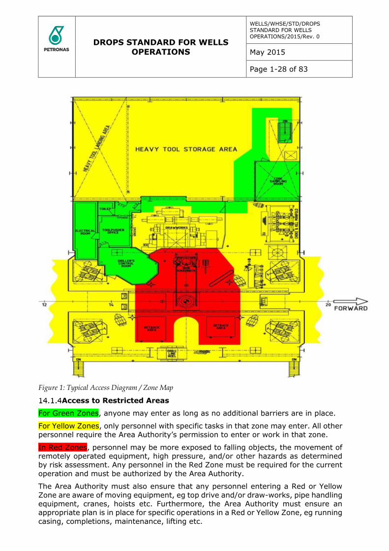
Access Diagrams / Zone Maps
Access diagrams or Zone Maps should be prepared and mounted (where practicable) at all access points to Red or Yellow Zones and at the common workplace of the relevant Area Authority. The diagrams should clearly define and demarcate Red,
Yellow and Green zones, as well as access and egress routes. They should identify the Area Authority’s common workplace location and show green zone access to and
from that location.
Figure 1 is an example of an Access Diagram / Zone Map for a typical Drill Floor where the Driller is the Area Authority and his common workplace is the Drillers’
Control Room.
DROPS STANDARD FOR WELLS OPERATIONS
WELLS/WHSE/STD/DROPS STANDARD FOR WELLS OPERATIONS/2015/Rev. 0
May 2015
Page 1-28 of 83
Figure 1: Typical Access Diagram / Zone Map
Access to Restricted Areas
For Green Zones, anyone may enter as long as no additional barriers are in place.
For Yellow Zones, only personnel with specific tasks in that zone may enter. All other personnel require the Area Authority’s permission to enter or work in that zone.
In Red Zones, personnel may be more exposed to falling objects, the movement of remotely operated equipment, high pressure, and/or other hazards as determined by risk assessment. Any personnel in the Red Zone must be required for the current
operation and must be authorized by the Area Authority.
The Area Authority must also ensure that any personnel entering a Red or Yellow
Zone are aware of moving equipment, eg top drive and/or draw-works, pipe handling equipment, cranes, hoists etc. Furthermore, the Area Authority must ensure an appropriate plan is in place for specific operations in a Red or Yellow Zone, eg running
casing, completions, maintenance, lifting etc.
DROPS STANDARD FOR WELLS OPERATIONS
WELLS/WHSE/STD/DROPS STANDARD FOR WELLS OPERATIONS/2015/Rev. 0
May 2015
Page 1-29 of 83
Additional personnel may not under any circumstances join a task being conducted in a Red or Yellow Zone until a Time Out For Safety (TOFS) has been called and the plan discussed. They must have a specific responsibility during the task, understand
the placement of personnel, and be aware of machinery which may be operated during the task. Potential dropped objects and any other identified hazards must also
be discussed.
The Area Authority, once satisfied, must give approval before the task can resume.
14.1.4.1 Permission to enter Restricted Areas
Every effort should be made to identify and define an access route to the Area Authority’s common workplace location within the Green Zone. This will allow
personnel access to the Area Authority to request authorization into the Yellow and Red Zones. Authorization requests should be conducted in a manner that provides minimal distraction to the Area Authority.
Personnel not required for current operations must not be permitted into Yellow or Red Zones.
For any activities that require entry to a Red Zone, and for non-routine activities within a Yellow Zone, a documented risk assessment must be performed before permission is given.
A Task or Job Risk Assessment should be performed when:
Any part of the activity is not covered by existing procedures
There is conflict between procedures Those personnel involved in the task are not familiar with the activities Those personnel involved in the task have not been involved in this type of
operation for a long period.
A Toolbox Talk should be undertaken where a Task or Job Risk Assessment is not
required. The Toolbox Talk should fully review the established operating procedure and all participants should have a copy in hand.
When any activity within the Red Zone or a non-routine activity within the Yellow
Zone has been completed, the performing individual(s) shall inform the Area Authority. On notification that the task is completed, the Area Authority shall
immediately withdraw the permission to enter the zone.
14.1.4.2 Controlling Access to Restricted Areas
Access to Red or Yellow Zones must be controlled at all times. All access points should be identified and equipped with
a physical barrier marking the point at which personnel cannot proceed
without approval from the Area Authority. The physical barrier may be a chain, gate, door etc. (Emergency
egress must not be impeded.) The barrier shall always be in place at all
access points leading directly to Yellow and Red Zones, and at any other access points determined by the Area Authority.
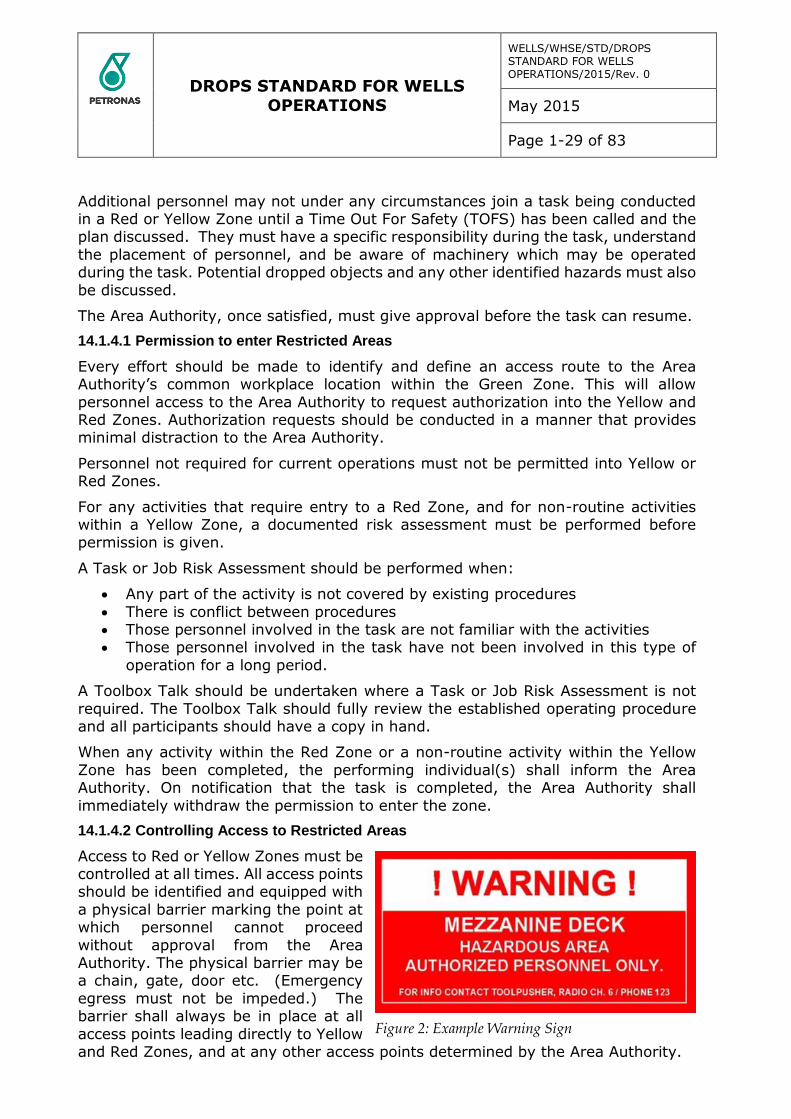
Figure 2: Example Warning Sign

DROPS STANDARD FOR WELLS OPERATIONS
WELLS/WHSE/STD/DROPS STANDARD FOR WELLS OPERATIONS/2015/Rev. 0
May 2015
Page 1-30 of 83
Figure 3: Example Red Zone Marking Techniques
The physical barrier should also include a sign (in both English and the predominant local language) that communicates the zone is a hazardous area and access requires
the Area Authority’s authorization (see example shown as Figure 2). Additional examples of Zone entry marking techniques are shown in Figure 3.
14.1.4.3 Permanent Changes to Restriction Classification
It may become necessary to reclassify a restricted area in response to permanent modifications or changes in operation within that zone. Such permanent changes to
zone classification should be captured through the formal Management of Change (MOC) process and will require amendment and reposting of the relevant Access
Diagrams.
14.1.4.4 Temporary Changes to Restriction Classification
It may become necessary to temporarily reclassify or restrict an area in response
operational, environmental or other conditions, eg scaffold erection maintenance intervention, pressure testing, high winds etc.
In such temporary circumstances, the Area Authority will determine the reclassification and will be responsible for permissions to enter the area. Temporary
physical barriers should be placed at all entry points to the reclassified area. Emergency egress must not be impeded and the barriers should be easy to store when access is unrestricted. Signage must also be posted at all access points
denoting the temporary zone classification, the restricted access and the respective Area Authority. The temporary sign should be in English and the predominant local
language. The Area Authority should arrange for PA announcements reflecting the temporary reclassification and access restrictions.
Temporary barriers and signage should be completely removed when the Area
Authority has deemed the area can return to its normal and permanent classification.
Method of Verification
Verify all equipment (at height) which is included in picture book. Verify equipment secondary fastenings meet the requirements. Review the picture book for details and information.
Verify all lifting and handling equipment is in the register, certified and within date.
Verify that all relevant safety alerts have been received and actioned.
DROPS STANDARD FOR WELLS OPERATIONS
WELLS/WHSE/STD/DROPS STANDARD FOR WELLS OPERATIONS/2015/Rev. 0
May 2015
Page 1-31 of 83
A record of failed items, with reason for failure, is to be maintained and is to be available for review by PCSB.
15 TASK PLANNING
For all tasks, routine or otherwise, a plan should be developed with appropriate assessment of the risk of potential dropped objects and other hazards. The plan
should identify all potential dropped objects and implement preventive and mitigating controls to prevent their occurrence.
The plan should provide for continuous observation and monitoring of the task, as
well as ‘Time Out for Safety’ (planned or unplanned).
While undertaking the task, changes must be monitored, evaluated and
appropriately responded to. This may require revision of the plan or development of a new plan, but in all cases work should be suspended if the task cannot be safely continued.
Before starting work
Before commencing any task and even with the task plan in place (see Task
Planning), it is important to consider the potential for dropped objects:
Consider the environment where you will perform the task and any other activities that may be going on around you.
Review any Lift Plan or Collision Checklist, as appropriate. Visually inspect the work area for loose items and debris. Check the equipment
and structures in the work area to ensure that any fasteners, bolting, covers etc are properly secured.
Check that secondary retention is in place for all items secured above the work
area, eg lighting, PA equipment etc.
See Appendix 20.6 – DROPS Pre-task Checklist.
Working at Height
When working at height, the potential for dropped objects is greater and continuous vigilance is critical:
Use only tools and equipment approved for work at height, including the appropriate lanyards and toolbags, and always log tools in and out on the tool
register. Set up barriers beneath the work area and ensure the extent of the barriered
zone is appropriate to the work height, with due consideration of the potential
deflection or ‘bounce’ of a dropped object. Check grating is secure and use mats where there is the potential for small
items to fall through grating. Where a scaffolding platform is employed, ensure toe-boards are installed.
Remain vigilant of other activities going on around you and below you.
Tasks involving Loading of Lifting
Where the task involves loading or lifting, a Lifting Plan may be necessary as part of
the pre-task planning process and additional checks will be required:
DROPS STANDARD FOR WELLS OPERATIONS
WELLS/WHSE/STD/DROPS STANDARD FOR WELLS OPERATIONS/2015/Rev. 0
May 2015
Page 1-32 of 83
Ensure the lifting equipment, carrier or packaging is appropriate for the task and in good order.
Ensure containerized loads are properly stacked, stored and secured.
Check tubulars for items left inside and employ cap ends, where practicable. Check tops of containers and fork lift pockets for loose items and debris.
For tasks involving packing and handling of cargo, refer to Appendix 20.10 – Example Packing and Handling Checklist.
Task Completion
On completion of the task, it is essential to leave the worksite safe and tidy:
Clear all scrap, debris and loose items from the worksite.
Return all tools and complete the Tools aloft Log. Remove all temporary barriers and signage. Note and communicate any lessons learned in undertaking the task.
Lift Plans
Prior to any lifting operation, it is essential that certain precautions are taken. For
routine lifts, these precautions are detailed in our documented procedures, but for all non-routine activities, a Lifting Plan and an associated risk assessment must be developed by a competent and trained person. See Appendix 20.9.
As well as assuring that all personnel involved in the lift are clearly aware of the operation and their roles / responsibilities, these procedures and Lift Plans ensure
that:
Checks are always carried out in accordance with industry standards Lifting equipment is certified for current use
Restrictions and fastenings are removed Effective communication systems are in place
There is adequate light and space to undertake the activity.
A toolbox talk must always be held before any lifting operation to discuss the task in detail and identify all potential hazards and mitigate the risks, including the potential
for dropped objects.
Collision Checklist
Collision checklists are recommended for installations and facilities with cranes, derricks, towers or tall structures housing moving equipment. For a typical drilling rig or offshore installation, it is recommended that a Crane Operator’s Collision
Checklist is developed for each crane along with a Driller’s Collision Checklist. See Appendices 20.7 and 20.8 for examples.
The Collision Checklist is effectively a prompt card for the equipment operator to review before undertaking a task. It highlights all possible obstructions that may
result in a dynamic dropped object if there were a collision.
For cranes, the Collision Checklist should identify any equipment that a load could collide with during a lifting operation. The checklist may be organized by boom angles
and it must be readily available at the crane controls.

DROPS STANDARD FOR WELLS OPERATIONS
WELLS/WHSE/STD/DROPS STANDARD FOR WELLS OPERATIONS/2015/Rev. 0
May 2015
Page 1-33 of 83
For Drilling, the Collision Checklist should include any equipment that may obstruct the path of the blocks and any equipment suspended from the blocks. This includes equipment that is normally out of the path, but may be moved into a position where
a collision may occur. The Driller’s Collision Checklist must be readily available at the Driller’s and Assistant Driller’s controls.
All equipment and loads shall be inspected onshore prior to loading onto transportation to the unit. All equipment and loads shall be inspected again offshore immediately before lifting onto the unit. Similarly, all equipment shall be inspected
before lifting off the unit.
The inspection shall cover all potential items that may cause a DROPS incident (as a
minimum):
Certified lifting points and lifting equipment, certified containers Secure fixings
Loose objects Adequate retention of items that could potentially come loose (doors and
hatches) General condition of pallets and sacks Internal inspection of tubulars (when no suitable closed end protectors are
installed)
Area authorities are to be assigned to be responsible for specific areas; all areas of
the installation are to be covered. The number of area authorities depends on the size and complexity of the installation. The area authorities shall be familiar with the operations in their respective areas and report to the PIC.
A matrix of area authorities’ roles, responsibilities and required competence shall be maintained.
Area authorities are responsible for ensuring adequate physical barriers and signs are installed in their respective areas. They are also to ensure that emergency escapes are not blocked or hindered because of these barriers.
When non routine operations are to be performed, the respective area authorities are to perform a risk assessment and adequately prepare the area. Similarly, when
adverse weather or operating conditions are expected, all area authorities will conduct risk assessments and take measures in regards to the potential increase in risk of dropped objects.
DROPS STANDARD FOR WELLS OPERATIONS
WELLS/WHSE/STD/DROPS STANDARD FOR WELLS OPERATIONS/2015/Rev. 0
May 2015
Page 1-34 of 83
16 TOOLS AND EQUIPMENT
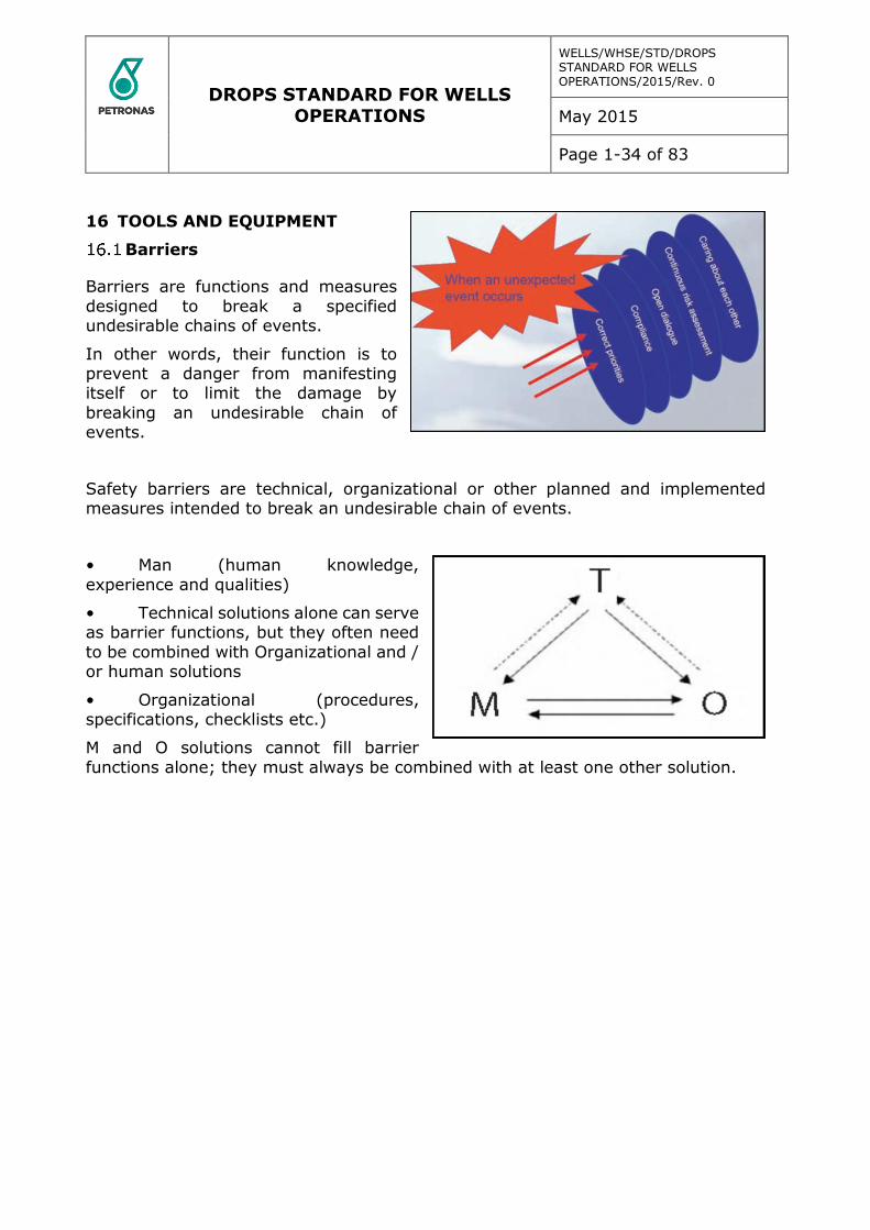
Barriers
Barriers are functions and measures
designed to break a specified undesirable chains of events.
In other words, their function is to prevent a danger from manifesting itself or to limit the damage by
breaking an undesirable chain of events.
Safety barriers are technical, organizational or other planned and implemented measures intended to break an undesirable chain of events.
• Man (human knowledge,
experience and qualities)
• Technical solutions alone can serve as barrier functions, but they often need
to be combined with Organizational and / or human solutions
• Organizational (procedures, specifications, checklists etc.)
M and O solutions cannot fill barrier
functions alone; they must always be combined with at least one other solution.
DROPS STANDARD FOR WELLS OPERATIONS
WELLS/WHSE/STD/DROPS STANDARD FOR WELLS OPERATIONS/2015/Rev. 0
May 2015
Page 1-35 of 83
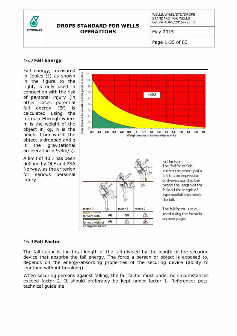
Fall Energy
Fall energy, measured in Joules (J) as shown
in the figure to the right, is only used in
connection with the risk of personal injury (in other cases potential
fall energy (Ef) is calculated using the
formula Ef=mgh where m is the weight of the object in kg, h is the
height from which the object is dropped and g
is the gravitational acceleration = 9.8m/s).
A limit of 40 J has been
defined by OLF and PSA Norway, as the criterion
for serious personal injury.
Fall Factor
The fall factor is the total length of the fall divided by the length of the securing device that absorbs the fall energy. The force a person or object is exposed to, depends on the energy-absorbing properties of the securing device (ability to
lengthen without breaking).
When securing persons against falling, the fall factor must under no circumstances
exceed factor 2. It should preferably be kept under factor 1. Reference: petzl technical guideline.
DROPS STANDARD FOR WELLS OPERATIONS
WELLS/WHSE/STD/DROPS STANDARD FOR WELLS OPERATIONS/2015/Rev. 0
May 2015
Page 1-36 of 83
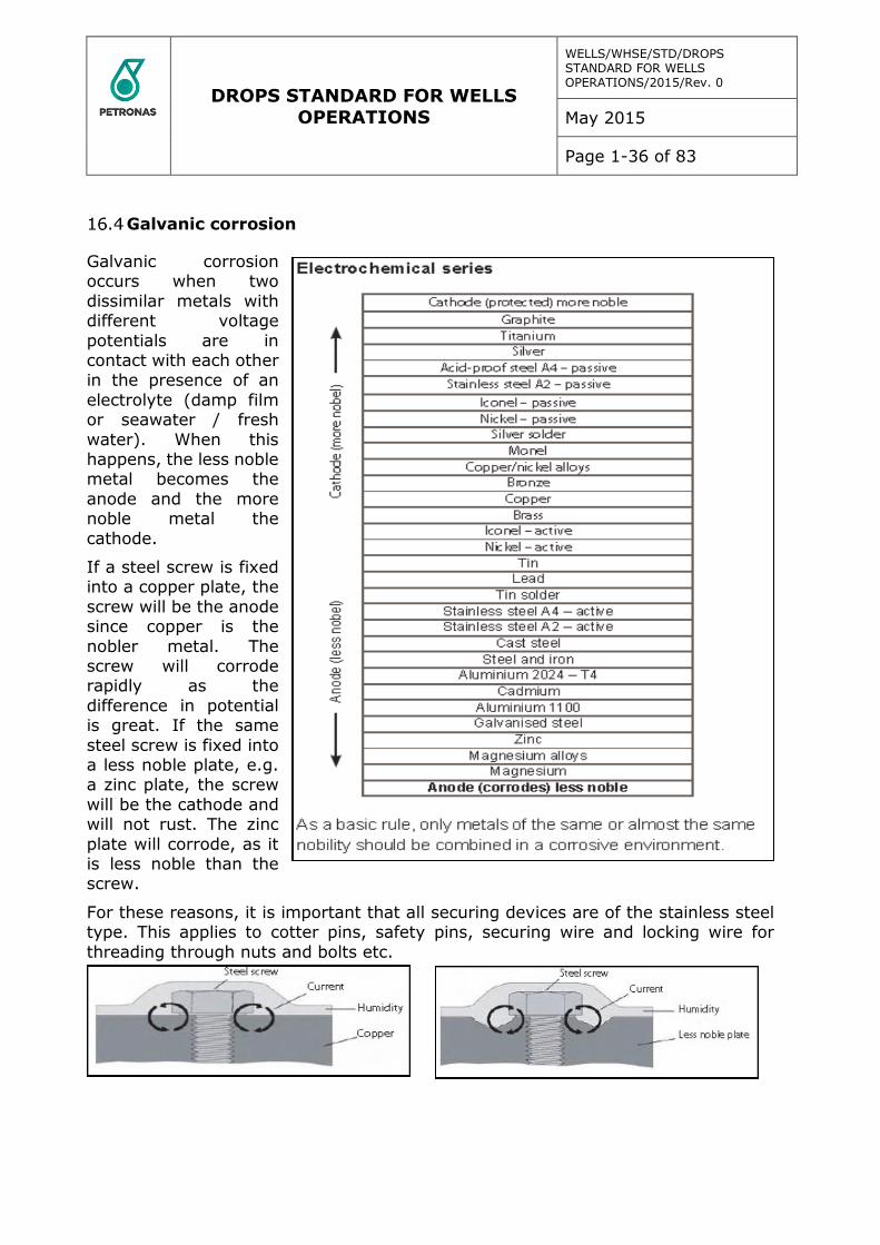
Galvanic corrosion
Galvanic corrosion occurs when two
dissimilar metals with different voltage
potentials are in contact with each other in the presence of an
electrolyte (damp film or seawater / fresh
water). When this happens, the less noble metal becomes the
anode and the more noble metal the
cathode.
If a steel screw is fixed into a copper plate, the
screw will be the anode since copper is the
nobler metal. The screw will corrode rapidly as the
difference in potential is great. If the same
steel screw is fixed into a less noble plate, e.g. a zinc plate, the screw
will be the cathode and will not rust. The zinc
plate will corrode, as it is less noble than the screw.
For these reasons, it is important that all securing devices are of the stainless steel type. This applies to cotter pins, safety pins, securing wire and locking wire for
threading through nuts and bolts etc.
DROPS STANDARD FOR WELLS OPERATIONS
WELLS/WHSE/STD/DROPS STANDARD FOR WELLS OPERATIONS/2015/Rev. 0
May 2015
Page 1-37 of 83
Bolted Connections
At present, bolts are being produced to at least 85 different industrial standards and the requirements for bolted connections vary for the different sectors depending on
the given design, operational and maintenance requirements.
Achieving a stable bolted connection will therefore require a qualified evaluation of
the following factors:
Load design Choice of materials with respect to mechanical
Properties and corrosion resistance Where appropriate, use of lubricant Pre-tensioning and use of the correct
torque equipment
Locking of bolts to secure against loss of torque and pre-tension is defined as secondary retention.
Eighty-five per cent of all damage to bolts etc. is due to fatigue:
- Dynamic load with inadequate pre-tensioning
- Overstrain resulting in reduced pre-tensioning
Special Bolts
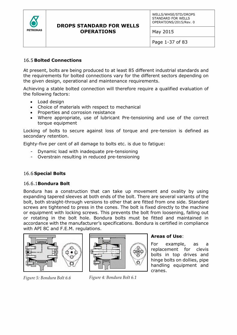
Bondura Bolt
Bondura has a construction that can take up movement and ovality by using expanding tapered sleeves at both ends of the bolt. There are several variants of the
bolt, both straight-through versions to other that are fitted from one side. Standard screws are tightened to press in the cones. The bolt is fixed directly to the machine or equipment with locking screws. This prevents the bolt from loosening, falling out
or rotating in the bolt hole. Bondura bolts must be fitted and maintained in accordance with the manufacturer’s specifications. Bondura is certified in compliance
with API 8C and F.E.M. regulations.
Areas of Use:
For example, as a
replacement for clevis bolts in top drives and
hinge bolts on dollies, pipe handling equipment and cranes.
Figure 5: Bondura Bolt 6.6 Figure 4: Bondura Bolt 6.1

DROPS STANDARD FOR WELLS OPERATIONS
WELLS/WHSE/STD/DROPS STANDARD FOR WELLS OPERATIONS/2015/Rev. 0
May 2015
Page 1-38 of 83
Superbolt / Supernut
Superbolt / Supernut are constructed such that standard nuts are replaced by “stretch nuts” with
integrated jackbolts and washers. Use can be very beneficial in terms of HSE because only
hand tools are needed for fitting and dismantling. Rigging of heavy torque equipment and use of sledgehammers during installation and
disassembly is avoided. An additional benefit is that time is saved during the operations. Bolts
must be fitted and maintained in accordance with the manufacturer’s specifications. Both Superbolt and Supernut is available in a special corrosion resistant offshore version.
Areas of use:
Almost unlimited; available in both inch and millimeter dimensions and diameters
from M20 to M160
17 Bolted Connections
Nord-Lock Bolt Securing System
When correctly installed, the Nord-Lock Bolt securing system provides a guaranteed secure bolted
connection. Locking is achieved by means of two washers that ensure the clamping force is maintained in the bolted connection. Nord-Lock has DNV (Det
Norske Veritas) type approval.
Areas of use:
Particularly suitable for connections exposed to vibrations, e.g. grating, loudspeakers, cable trays, ladders, guide rails etc. But it has an almost unlimited
range of applications.
DROPS STANDARD FOR WELLS OPERATIONS
WELLS/WHSE/STD/DROPS STANDARD FOR WELLS OPERATIONS/2015/Rev. 0
May 2015
Page 1-39 of 83
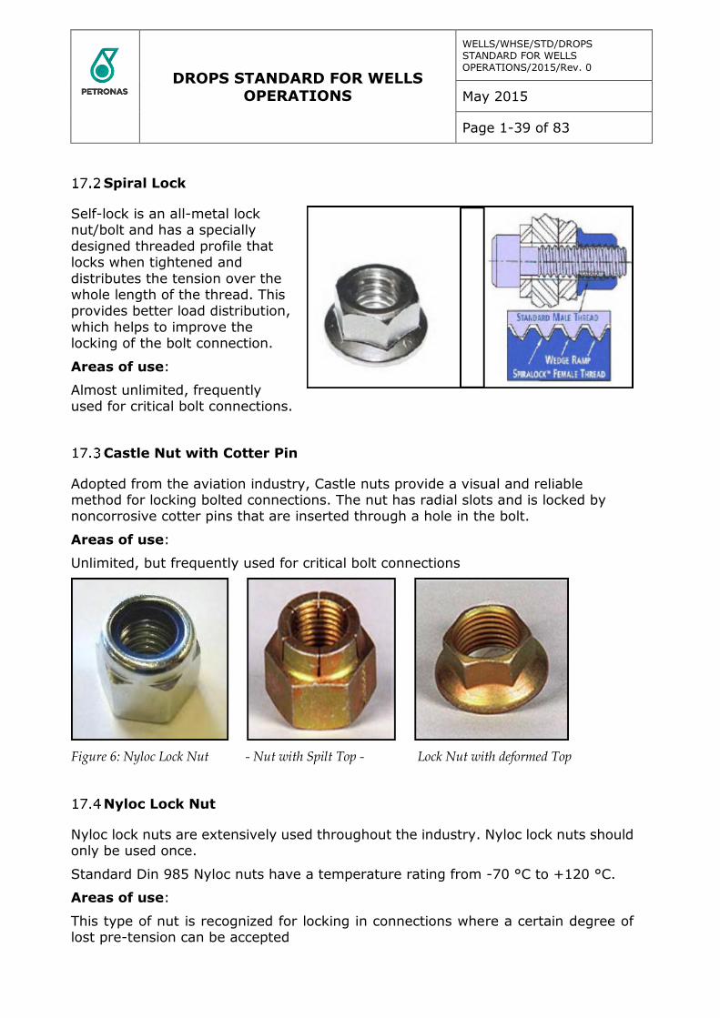
Spiral Lock
Self-lock is an all-metal lock nut/bolt and has a specially
designed threaded profile that locks when tightened and
distributes the tension over the whole length of the thread. This provides better load distribution,
which helps to improve the locking of the bolt connection.
Areas of use:
Almost unlimited, frequently used for critical bolt connections.
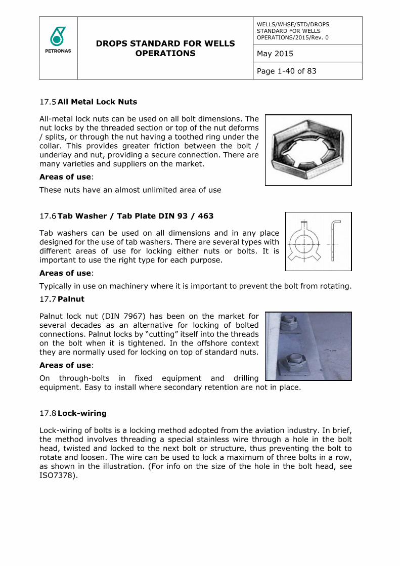
Castle Nut with Cotter Pin
Adopted from the aviation industry, Castle nuts provide a visual and reliable method for locking bolted connections. The nut has radial slots and is locked by noncorrosive cotter pins that are inserted through a hole in the bolt.
Areas of use:
Unlimited, but frequently used for critical bolt connections
Figure 6: Nyloc Lock Nut - Nut with Spilt Top - Lock Nut with deformed Top
Nyloc Lock Nut
Nyloc lock nuts are extensively used throughout the industry. Nyloc lock nuts should only be used once.
Standard Din 985 Nyloc nuts have a temperature rating from -70 °C to +120 °C.
Areas of use:
This type of nut is recognized for locking in connections where a certain degree of lost pre-tension can be accepted
DROPS STANDARD FOR WELLS OPERATIONS
WELLS/WHSE/STD/DROPS STANDARD FOR WELLS OPERATIONS/2015/Rev. 0
May 2015
Page 1-40 of 83
All Metal Lock Nuts
All-metal lock nuts can be used on all bolt dimensions. The nut locks by the threaded section or top of the nut deforms
/ splits, or through the nut having a toothed ring under the collar. This provides greater friction between the bolt /
underlay and nut, providing a secure connection. There are many varieties and suppliers on the market.
Areas of use:
These nuts have an almost unlimited area of use
Tab Washer / Tab Plate DIN 93 / 463
Tab washers can be used on all dimensions and in any place designed for the use of tab washers. There are several types with
different areas of use for locking either nuts or bolts. It is important to use the right type for each purpose.
Areas of use:
Typically in use on machinery where it is important to prevent the bolt from rotating.
Palnut
Palnut lock nut (DIN 7967) has been on the market for several decades as an alternative for locking of bolted
connections. Palnut locks by “cutting” itself into the threads on the bolt when it is tightened. In the offshore context they are normally used for locking on top of standard nuts.
Areas of use:
On through-bolts in fixed equipment and drilling
equipment. Easy to install where secondary retention are not in place.
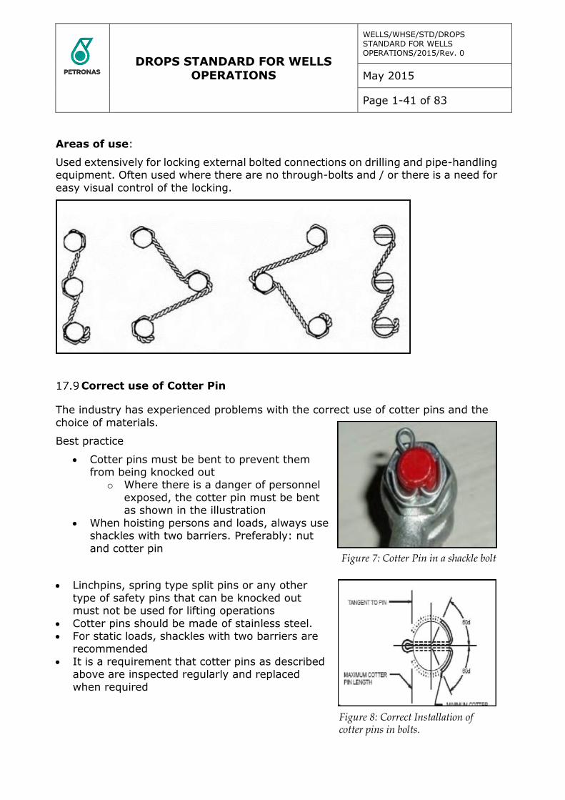
Lock-wiring
Lock-wiring of bolts is a locking method adopted from the aviation industry. In brief, the method involves threading a special stainless wire through a hole in the bolt
head, twisted and locked to the next bolt or structure, thus preventing the bolt to rotate and loosen. The wire can be used to lock a maximum of three bolts in a row, as shown in the illustration. (For info on the size of the hole in the bolt head, see
ISO7378).
DROPS STANDARD FOR WELLS OPERATIONS
WELLS/WHSE/STD/DROPS STANDARD FOR WELLS OPERATIONS/2015/Rev. 0
May 2015
Page 1-41 of 83
Areas of use:
Used extensively for locking external bolted connections on drilling and pipe-handling equipment. Often used where there are no through-bolts and / or there is a need for
easy visual control of the locking.
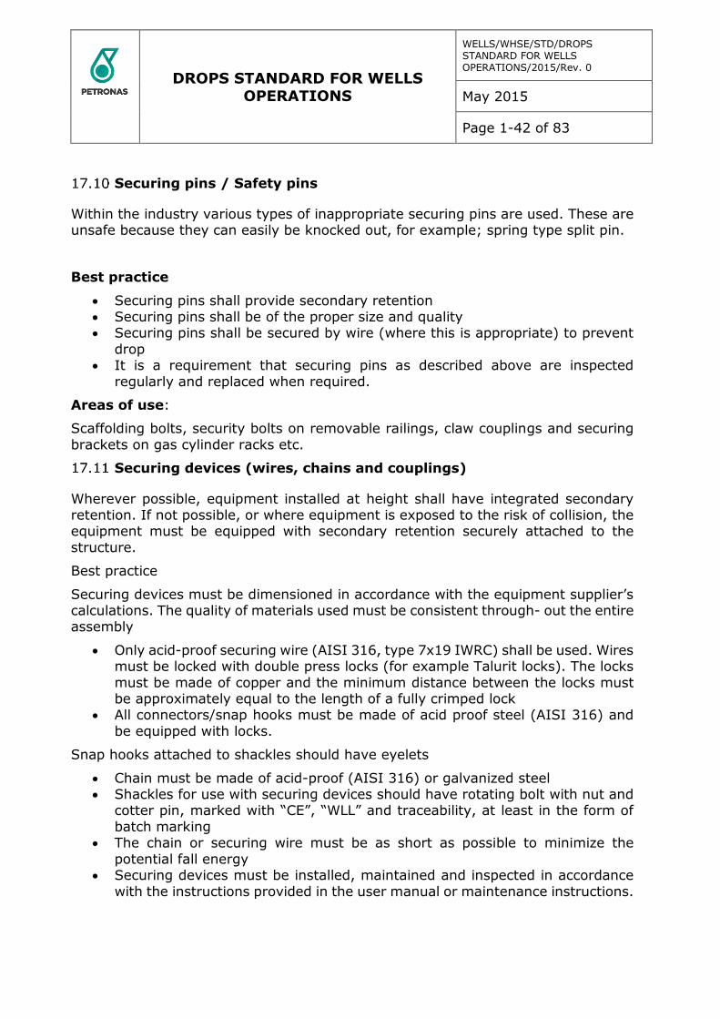
Correct use of Cotter Pin
The industry has experienced problems with the correct use of cotter pins and the
choice of materials.
Best practice
Cotter pins must be bent to prevent them from being knocked out
o Where there is a danger of personnel
exposed, the cotter pin must be bent as shown in the illustration
When hoisting persons and loads, always use shackles with two barriers. Preferably: nut
and cotter pin
Linchpins, spring type split pins or any other
type of safety pins that can be knocked out must not be used for lifting operations
Cotter pins should be made of stainless steel. For static loads, shackles with two barriers are
recommended
It is a requirement that cotter pins as described above are inspected regularly and replaced
when required
Figure 7: Cotter Pin in a shackle bolt
Figure 8: Correct Installation of cotter pins in bolts.
DROPS STANDARD FOR WELLS OPERATIONS
WELLS/WHSE/STD/DROPS STANDARD FOR WELLS OPERATIONS/2015/Rev. 0
May 2015
Page 1-42 of 83
Securing pins / Safety pins
Within the industry various types of inappropriate securing pins are used. These are unsafe because they can easily be knocked out, for example; spring type split pin.
Best practice
Securing pins shall provide secondary retention Securing pins shall be of the proper size and quality Securing pins shall be secured by wire (where this is appropriate) to prevent
drop It is a requirement that securing pins as described above are inspected
regularly and replaced when required.
Areas of use:
Scaffolding bolts, security bolts on removable railings, claw couplings and securing
brackets on gas cylinder racks etc.
Securing devices (wires, chains and couplings)
Wherever possible, equipment installed at height shall have integrated secondary retention. If not possible, or where equipment is exposed to the risk of collision, the equipment must be equipped with secondary retention securely attached to the
structure.
Best practice
Securing devices must be dimensioned in accordance with the equipment supplier’s calculations. The quality of materials used must be consistent through- out the entire assembly
Only acid-proof securing wire (AISI 316, type 7x19 IWRC) shall be used. Wires must be locked with double press locks (for example Talurit locks). The locks
must be made of copper and the minimum distance between the locks must be approximately equal to the length of a fully crimped lock
All connectors/snap hooks must be made of acid proof steel (AISI 316) and
be equipped with locks.
Snap hooks attached to shackles should have eyelets
Chain must be made of acid-proof (AISI 316) or galvanized steel Shackles for use with securing devices should have rotating bolt with nut and
cotter pin, marked with “CE”, “WLL” and traceability, at least in the form of
batch marking The chain or securing wire must be as short as possible to minimize the
potential fall energy Securing devices must be installed, maintained and inspected in accordance
with the instructions provided in the user manual or maintenance instructions.

DROPS STANDARD FOR WELLS OPERATIONS
WELLS/WHSE/STD/DROPS STANDARD FOR WELLS OPERATIONS/2015/Rev. 0
May 2015
Page 1-43 of 83
Correct installation of wire clamps
Corrosion and incorrect installation of wire clamps are challenges in the industry
Best practice
Wire clamps must be of the correct number and sized to the dimension of the
wire It is a requirement that wire clamps are assembled, inspected and maintained
in accordance with the manufacturer’s user manual / maintenance instructions.
Note: Wire clamps of the U-bolt type must not be used in connection with lifting
operations.
DROPS STANDARD FOR WELLS OPERATIONS
WELLS/WHSE/STD/DROPS STANDARD FOR WELLS OPERATIONS/2015/Rev. 0
May 2015
Page 1-44 of 83
18 Securing of personnel
Documented training is a mandatory requirement for all personnel using fall arrests.
Best practice
The established control procedures, both before and after use, must be
followed Nobody shall work alone or unattended, when using fall arrest equipment Personal using fall protection equipment must have documented training that
includes rescue methods. Necessary rescue equipment must always be available at the work site
Personal protective equipment against falls must be CE marked The equipment must be checked at least every 6 months by a competent
person and shall be marked with the date for the next inspection
A buddy check of rigging and equipment must be carried out Choice of securing equipment, shall be decided after evaluation of the work
site The anchor point for suspension shall be able to support at least 10kN (see
requirement in NEN795)
The harness should preferably be equipped with a safety strap. (E.g.: SALA trauma strap, which allows you to rest on your feet after a fall, in order to
ensure blood circulation to the legs
Derrick Evacuation Equipment
Best practice
Equipment must be protected from wear and harsh environment
Equipment should be stored in cabinet/locker to protected it from UV radiation and weather
Evacuation blocks must be CE-marked
The riding belt or harness must be attached to the evacuation block or to the guide line where appropriate
Evacuation block, guide line, attachment point, couplings and shackles are defined as evacuation equipment / anti-falling devices and must be checked, certified and marked accordingly
Anchor points for suspension must be able to support at least 10kN The equipment must be checked at least every 6 months by a competent
person and shall be marked with the next inspection date Safe access to and use of the equipment must be ensured.
DROPS STANDARD FOR WELLS OPERATIONS
WELLS/WHSE/STD/DROPS STANDARD FOR WELLS OPERATIONS/2015/Rev. 0
May 2015
Page 1-45 of 83
Securing of tools at height (<5kg)
There is a significant potential of dropped objects when using tools at height.
Best practice
Use of tools at height must be risk-assessed Wires and connectors must be used between the tools, belt or bag
Swivels with set screws should not be used Weak link shall be installed between the bag/ belt and safety wire A tool bag with internal loops should be used when various tools are deployed
at height Wrist straps must not be used because of potential personal injury
If an attachment point other than the belt or bag is required, use an appropriate part of the surrounding structure, preferably above the work level
In limited areas, for example the derrick, flare boom and cranes, tools used
at height must be logged out and in to ensure that nothing is left behind.
Securing of tools at height (5-25kg)
Methods for securing heavy tools and hand-held machinery for use at height have not been adequately defined. In view of the major potential for serious damage if
such tools or machinery are dropped, it is important to have clear guidelines.
Best practice
All use of heavy tools and hand-held machinery at height must be risk-assessed
All heavy tools and hand-held machinery used at height must be secured
against drop both when in use and while being transported Securing devices must be dimensioned in accordance with verifiable
calculations and documented drop tests (see the section on securing devices) Securing points for tools and machinery must be in place above the work site
and the securing device must be as taut as possible
In limited areas, for example the derrick, flare boom and cranes, tools used at height must be logged out and in to ensure that nothing is left behind.
Securing of other portable equipment at height
Several of reported dropped object incidents are related to radios, pagers and gas detectors.
Best practice
All portable equipment used at height must be secured against being dropped
Carrying pouches must always be used for radios and any other portable equipment that don’t have certified securing points
o Locks on the pouches must have a double securing mechanism to prevent unintentional opening
Belt clips which allow equipment to become detached when turned 180º
should not be used

DROPS STANDARD FOR WELLS OPERATIONS
WELLS/WHSE/STD/DROPS STANDARD FOR WELLS OPERATIONS/2015/Rev. 0
May 2015
Page 1-46 of 83
Belts with snap fasteners are not recommended for securing of equipment at height.
Tool cabinets for work at height
Tool cabinets/lockers for work at height have to be installed on the facility, offshore
in most cases near the drill floor. Unfortunately, a number of irregularities have been observed regarding securing, control and registration of tools.
Best practice
Each cabinet/locker shall be equipped with a list of contents and be kept locked.
A designated person must be responsible for the cabinet to ensure that all
tools taken from and returned to the cabinet are logged The contents of the tool cabinet for work at height and its accompanying log
book must be checked at the end of every shift
All tools must be adequately equipped for securing at height and must have documented attachment points
In addition to the necessary tools, cabinets should be equipped with a sufficient number of:
- Correctly dimensioned safety wires with approved swage locks
- Connectors / snap hooks with locking - Tool bags with internal fastening devices
- Special belts for fastening of tools and bag - Weak links for fastening between the harness/belt and safety wire.
Securing of permanently attached equipment grating
At present there are a number of different ways of fastening grating to underlying
structures or frames. As a result of vibrations and defective locking of fastening, there are incidents of loose grating and loose or missing fastening clips.
Best practice
Grating must be adequately fixed to underlying structures to prevent loosening due to vibrations or loads
Grating should be secured against major sideways displacement in all directions
Through-bolts or threaded connections with locknut, are recommended for
securing to structure Openings in the grating must not exceed 20 mm where personnel may traffic
the area below, and should otherwise not exceed 35 mm.
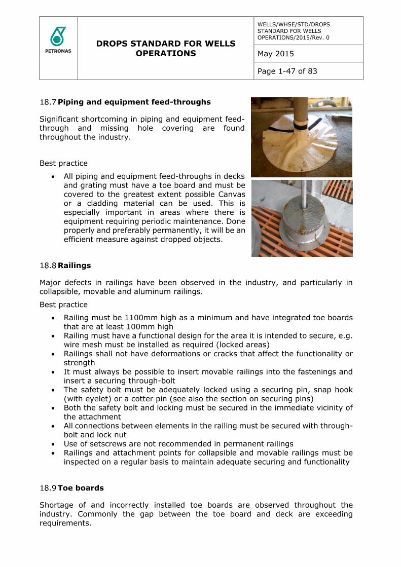
DROPS STANDARD FOR WELLS OPERATIONS
WELLS/WHSE/STD/DROPS STANDARD FOR WELLS OPERATIONS/2015/Rev. 0
May 2015
Page 1-47 of 83
Piping and equipment feed-throughs
Significant shortcoming in piping and equipment feed-through and missing hole covering are found
throughout the industry.
Best practice
All piping and equipment feed-throughs in decks and grating must have a toe board and must be
covered to the greatest extent possible Canvas or a cladding material can be used. This is
especially important in areas where there is equipment requiring periodic maintenance. Done properly and preferably permanently, it will be an
efficient measure against dropped objects.
Railings
Major defects in railings have been observed in the industry, and particularly in collapsible, movable and aluminum railings.
Best practice
Railing must be 1100mm high as a minimum and have integrated toe boards
that are at least 100mm high Railing must have a functional design for the area it is intended to secure, e.g.
wire mesh must be installed as required (locked areas)
Railings shall not have deformations or cracks that affect the functionality or strength
It must always be possible to insert movable railings into the fastenings and insert a securing through-bolt
The safety bolt must be adequately locked using a securing pin, snap hook
(with eyelet) or a cotter pin (see also the section on securing pins) Both the safety bolt and locking must be secured in the immediate vicinity of
the attachment All connections between elements in the railing must be secured with through-
bolt and lock nut
Use of setscrews are not recommended in permanent railings Railings and attachment points for collapsible and movable railings must be
inspected on a regular basis to maintain adequate securing and functionality
Toe boards
Shortage of and incorrectly installed toe boards are observed throughout the industry. Commonly the gap between the toe board and deck are exceeding
requirements.
DROPS STANDARD FOR WELLS OPERATIONS
WELLS/WHSE/STD/DROPS STANDARD FOR WELLS OPERATIONS/2015/Rev. 0
May 2015
Page 1-48 of 83
Best practice
Decks, gangways and platforms must have toe boards with a minimum height of 100mm
On stairways, every step must have a toe board with a minimum height of 50mm
All landings in stairways must have toe boards with a minimum height of 100mm
The gap between the deck or grating and toe board must not exceed 10mm.
Swing Gates
On many swing gates the hinges are fitted without the required material quality or design strength to serve the intended function. Many older gates also lack integrated toe boards.
Best practice
Gates must be of the same strength as the surrounding railings
Gates must be secured in order to prevent disengaging. Gates must open/swing inwards to the platform or deck Gates must be designed to automatically return to and remain in closed
position. On floating rigs / installations it is recommended to fit a latch to secure the
gate in closed position. Toe boards must be integrated in gates Wherever possible, the hinges should be an integral part of the gate
Swing gates must be inspected and maintained on a regular basis to ensure adequate function.
Ladders
Damaged ladders and safety cages have been observed in the industry. Cracks have been found in both ladders and cages, especially in derricks and are as a rule caused
by collision with moving equipment / objects.
Best practice
Ladders higher than 9m must have incorporated a rest platform every 6th m or be equipped with a fixed fall arrest device
Safety cages must be installed on ladders of more than 3 m and on shorter
ladders where there is a risk of falling to a lower level The safety cage must start at a maximum of 2.2 m above the deck / floor.
Minimize the distance between the upper part of the railing and the lower part of the cage, by using extra protection as appropriate where there is a risk of
falling to a lower level The safety cage must extend to at least 1.1 m above the top level The diameter of the safety cage must be at least 70-80 cm
All damage and deformation must be reported and corrected as soon as possible
Ladders and safety cages must be inspected on a regular basis to uncover cracks or damage.

DROPS STANDARD FOR WELLS OPERATIONS
WELLS/WHSE/STD/DROPS STANDARD FOR WELLS OPERATIONS/2015/Rev. 0
May 2015
Page 1-49 of 83
Floodlights
Floodlights are rarely adequately secured against drop caused by hits from moving
equipment.
Best practice
Floodlights must be positioned to prevent being hit by equipment/loads If there is a potential of the floodlights being hit by mobile equipment/loads,
they must either be protected with reinforced cages or be fitted with safety
wires Floodlights must be equipped with two independent barriers. The attachment
points should be integrated, for example with eye bolts threaded into the floodlight housing
Calculations must be available for attachment points and securing devices
related to the relevant fall energies Fastening devices for securing of equipment to bracket or structure should be
fitted with secondary retention Hatches for replacement of light bulbs must be hinged or secured with wire to
the floodlight housing/frame
For new installations or for installing securing devices on existing equipment, a user manual/ maintenance instructions should be available.
The instructions should also cover securing devices
Lighting Fixtures
There have been several serious incidents where both the cover and the casing have dropped.
Best practice
Lighting fixtures must be positioned to prevent being hit by mobile equipment/loads
Lighting fixtures and brackets should be fitted with secondary retention Safety wires attachment points should be integrated in both ends of the fixture
Battery packs must be fitted with secondary retention The earthing wire should be attached internally to function as a secondary
retention
Above walkways and other trafficked areas fixtures with power cable in from one side only, requires that the opposite end is secured with a safety wire
The cover should have hinges that can be fitted on either side The component rail should be hinged and must allow for adequate securing in
the closed position Strength of attachment points and securing devices, related to the relevant
fall energies must be evaluated
For new installations or when installing securing devices on existing fixtures, user manuals / maintenance instructions should be available. The instructions
must also cover securing devices.
DROPS STANDARD FOR WELLS OPERATIONS
WELLS/WHSE/STD/DROPS STANDARD FOR WELLS OPERATIONS/2015/Rev. 0
May 2015
Page 1-50 of 83
Navigation Lights
Best practice
The bolts used to attach navigation lights to brackets and structures should
be equipped with secondary retention Attachment brackets must have holes for attachment of safety wires
Cover for electrical connections must be hinged or secured with wire Strength of attachment points and securing devices, related to the relevant
fall energy must be evaluated
Navigation lights with sliding grooves for bolt attachment to the structure, are not recommended
For new installations or when installing securing devices on existing equipment, a user manual / maintenance instructions should be available. The instructions must also cover securing devices.
CCTV Cameras
Within the industry, it is identified that CCTV cameras have been inadequately secured.
Best practice (integrated solution)
CCTV camera location must be evaluated to prevent risk of being hit by moving equipment/loads
In areas where there is crane activity, cameras should be shielded by protective cages
The camera casing must be fastened to the bracket and structure with
adequate locking of attachment bolts The attachment point for securing devices should form an integrated part of
the camera casing and bracket Strength of attachment points and securing devices, related to the relevant
fall energies must be evaluated
For new installation or when installing securing devices on existing equipment, a user manual / maintenance instructions should be available. The instructions
should also cover securing devices.
Best practice (non-integrated solution)
CCTV camera location must be evaluated to prevent risk of being hit by moving equipment/loads
Where there is danger of the camera being struck by mobile equipment/loads, it must either be protected by a reinforced cage or be fitted with safety wire
to structure The camera should be fitted with two independent barriers on the camera
casing, the motorized pan-tilt zoom unit, the wiper motor and the lens cover
The camera casing and motorized pan-tilt-zoom unit should be attached to the bracket and structure with adequately locked attachment bolts
The attachment point for the securing devices should be integrated into the camera parts. Alternatively special clamps can be used as attachment points
DROPS STANDARD FOR WELLS OPERATIONS
WELLS/WHSE/STD/DROPS STANDARD FOR WELLS OPERATIONS/2015/Rev. 0
May 2015
Page 1-51 of 83
Calculations must be available for attachment points and securing devices, related to the relevant fall energies
For new installations or when installing securing devices on existing
equipment, a user manual / maintenance instructions should be available. The instructions should also cover securing devices.
Crane boom camera
Within the industry there have been several incidents where a crane camera has
been struck during lifting operations.
Best practice
Crane boom cameras must have two independent barriers Bolts used for attaching the crane boom camera to brackets and structures
should be fitted with secondary retention
Attachment points for the safety wire should be integrated as part of the camera casing. Alternatively, special clamps can be fitted round the camera
casing The safety wire must run from the camera casing through the camera bracket
and then through the attachment bracket before being attached securely to
the structure of the crane boom Calculations must be available for attachment points and securing devices,
related to the relevant fall energies For new installations or when installing securing devices on existing
equipment, a user manual / maintenance instructions should be available. The
instructions should also cover securing devices.
DROPS STANDARD FOR WELLS OPERATIONS
WELLS/WHSE/STD/DROPS STANDARD FOR WELLS OPERATIONS/2015/Rev. 0
May 2015
Page 1-52 of 83
Loudspeakers
Best practice
Loudspeakers location must be evaluated to prevent risk of being hit by
moving equipment/loads If there is a risk of being hit by mobile equipment / loads, loudspeakers must
either be protected by reinforced braces or equipped with a safety wire Bolts used to fasten loudspeakers to brackets and the structure should be
fitted with secondary retention, as an alternative a safety wire can be attached
between bracket and structure Strength of attachment points and securing devices, related to the relevant
fall energy must be evaluated For new installations or when installing securing devices on existing
equipment, a user manual / maintenance instructions must be available. The
instructions should also cover securing devices.
Junction boxes and cabinets installed at height
Within the industry it is revealed incorrect positioning of junction boxes and cabinets, defective suspension / fastening and inadequate securing of hatches, doors and
covers.
Best practice
Junction boxes and cabinets must be located where they do not obstruct passageways, evacuation routes or moving equipment
The type and design of attachment and safety devices must be in accordance
with calculated loads and known potential external stress factors Fastening devises for securing of equipment to bracket or structure shall be
fitted with secondary retention. Where there is danger of the equipment being struck by moving
equipment/loads, it must be protected by a reinforced cage or be fitted with
a safety wire. Covers must be secured by fasteners that are secured and locked to prevent
loosening, and must be secured with wire or chain. Hinged hatches/doors should be secured against unintended unhooking and
locking devices should be fitted with barrier against opening
As a minimum, the manufacturer’s instructions for installation and maintenance (user manual) must be complied with.
Cable trays and cable ladders
Best practice
Only approved bolt connections shall be used for fastening and couplings Cable fixing clamps with screw connections are used for safe and functional
securing of instrument cables When attaching the cable support system to a structure, the risk of galvanic
corrosion must be assessed and insulation considered where appropriate
DROPS STANDARD FOR WELLS OPERATIONS
WELLS/WHSE/STD/DROPS STANDARD FOR WELLS OPERATIONS/2015/Rev. 0
May 2015
Page 1-53 of 83
The user manual/ instructions for use must also provide guidelines for correct installation, both in the joints and the attachment
In addition, the user manual / instructions for use must provide guidelines for
necessary maintenance/ retightening and inspection of both electro-steel and bolt and screw connections.
Wind walls
Within the industry many damaged and loose plates have been revealed in wind
walls. This is due both to faulty installation and to external factors (collisions with mobile equipment and harsh environment).
Best practice
Wind-wall panels must be fastened to a separate support / structure and never to the main structure
Wind-wall panels must always be reinforced using horizontal steel beams in accordance with the design loads
Areas that are exposed to collision risk must have stronger corner mountings secured by through-bolts and lock nuts
The preferred attachment solution is through-bolts with washers and lock nuts
The user manual / instructions must also provide guidelines for correct installation of both joints and attachment points
Guidelines must be available on essential maintenance and inspection of wind- wall panels and their attachment points.
Signs
Sign installation methods have in many cases been found inadequate.
Best practice
The requirements of PETRONAS in respect to posting of signs must be followed Signs, brackets and frames for signs must always be securely attached and
the frames should be of metal and painted. Where the underlying material permits, sign frames should be attached using
through-bolts with lock nuts Fasteners used for attachment to brackets and structures should be fitted with
secondary retention
Identification tags that are painted or glued are recommended for identification of piping systems. On hot surfaces, identification tags should be
attached with plastic-coated steel bands.
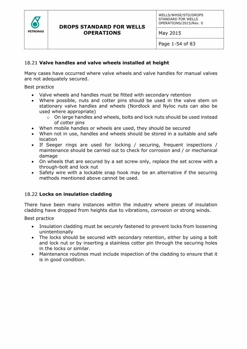
DROPS STANDARD FOR WELLS OPERATIONS
WELLS/WHSE/STD/DROPS STANDARD FOR WELLS OPERATIONS/2015/Rev. 0
May 2015
Page 1-54 of 83
Valve handles and valve wheels installed at height
Many cases have occurred where valve wheels and valve handles for manual valves are not adequately secured.
Best practice
Valve wheels and handles must be fitted with secondary retention
Where possible, nuts and cotter pins should be used in the valve stem on stationary valve handles and wheels (Nordlock and Nyloc nuts can also be used where appropriate)
o On large handles and wheels, bolts and lock nuts should be used instead of cotter pins
When mobile handles or wheels are used, they should be secured When not in use, handles and wheels should be stored in a suitable and safe
location
If Seeger rings are used for locking / securing, frequent inspections / maintenance should be carried out to check for corrosion and / or mechanical
damage On wheels that are secured by a set screw only, replace the set screw with a
through-bolt and lock nut
Safety wire with a lockable snap hook may be an alternative if the securing methods mentioned above cannot be used.
Locks on insulation cladding
There have been many instances within the industry where pieces of insulation
cladding have dropped from heights due to vibrations, corrosion or strong winds.
Best practice
Insulation cladding must be securely fastened to prevent locks from loosening unintentionally
The locks should be secured with secondary retention, either by using a bolt
and lock nut or by inserting a stainless cotter pin through the securing holes in the locks or similar.
Maintenance routines must include inspection of the cladding to ensure that it is in good condition.
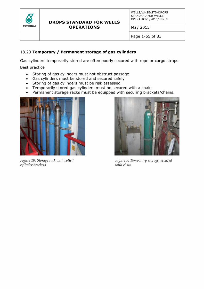
DROPS STANDARD FOR WELLS OPERATIONS
WELLS/WHSE/STD/DROPS STANDARD FOR WELLS OPERATIONS/2015/Rev. 0
May 2015
Page 1-55 of 83
Temporary / Permanent storage of gas cylinders
Gas cylinders temporarily stored are often poorly secured with rope or cargo straps.
Best practice
Storing of gas cylinders must not obstruct passage Gas cylinders must be stored and secured safely
Storing of gas cylinders must be risk assessed Temporarily stored gas cylinders must be secured with a chain Permanent storage racks must be equipped with securing brackets/chains.
Figure 10: Storage rack with bolted cylinder brackets
Figure 9: Temporary storage, secured with chain.
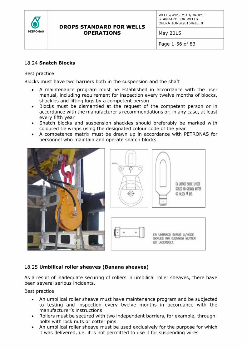
DROPS STANDARD FOR WELLS OPERATIONS
WELLS/WHSE/STD/DROPS STANDARD FOR WELLS OPERATIONS/2015/Rev. 0
May 2015
Page 1-56 of 83
Snatch Blocks
Best practice
Blocks must have two barriers both in the suspension and the shaft
A maintenance program must be established in accordance with the user manual, including requirement for inspection every twelve months of blocks,
shackles and lifting lugs by a competent person Blocks must be dismantled at the request of the competent person or in
accordance with the manufacturer’s recommendations or, in any case, at least
every fifth year Snatch blocks and suspension shackles should preferably be marked with
coloured tie wraps using the designated colour code of the year A competence matrix must be drawn up in accordance with PETRONAS for
personnel who maintain and operate snatch blocks.
Umbilical roller sheaves (Banana sheaves)
As a result of inadequate securing of rollers in umbilical roller sheaves, there have
been several serious incidents.
Best practice
An umbilical roller sheave must have maintenance program and be subjected
to testing and inspection every twelve months in accordance with the manufacturer’s instructions
Rollers must be secured with two independent barriers, for example, through-bolts with lock nuts or cotter pins
An umbilical roller sheave must be used exclusively for the purpose for which
it was delivered, i.e. it is not permitted to use it for suspending wires

DROPS STANDARD FOR WELLS OPERATIONS
WELLS/WHSE/STD/DROPS STANDARD FOR WELLS OPERATIONS/2015/Rev. 0
May 2015
Page 1-57 of 83
The umbilical must be installed on deck and the support rollers reinstalled and secured
A user manual/ maintenance instructions for the equipment must be available.
The instructions must cover installation, inspection and maintenance. Instruction must also include securing devices
Sheaves and suspension devices should preferably be marked with coloured tie wraps using the designated colour code of the year.
Loop hoses
Faulty installation or inadequate maintenance of loop hoses, and especially high-
pressure hoses, is a potential safety risk.
Best practice
The equipment manufacturer’s instructions for installation and technical
description must be followed Clamps must be attached and securely fastened where the hose is marked
with; “Attach safety clamp here” Safety chains must be as short as possible and installed as close to the vertical
as possible, to prevent fall energy and pendulum effect
Securing devices for hoses must be designed to support the maximum loads generated by a burst hose.
The design basis must be documented The required resistance to wear and tear, chemicals, heat and UV radiation
must also be documented
The securing system for hoses must be certified and traceable The securing devices must be checked and marked in accordance with the
norm for lifting appliances In addition to correct instructions for installation, the user manual/
maintenance instructions should contain guidelines for necessary maintenance
and inspection of the hose securing system.
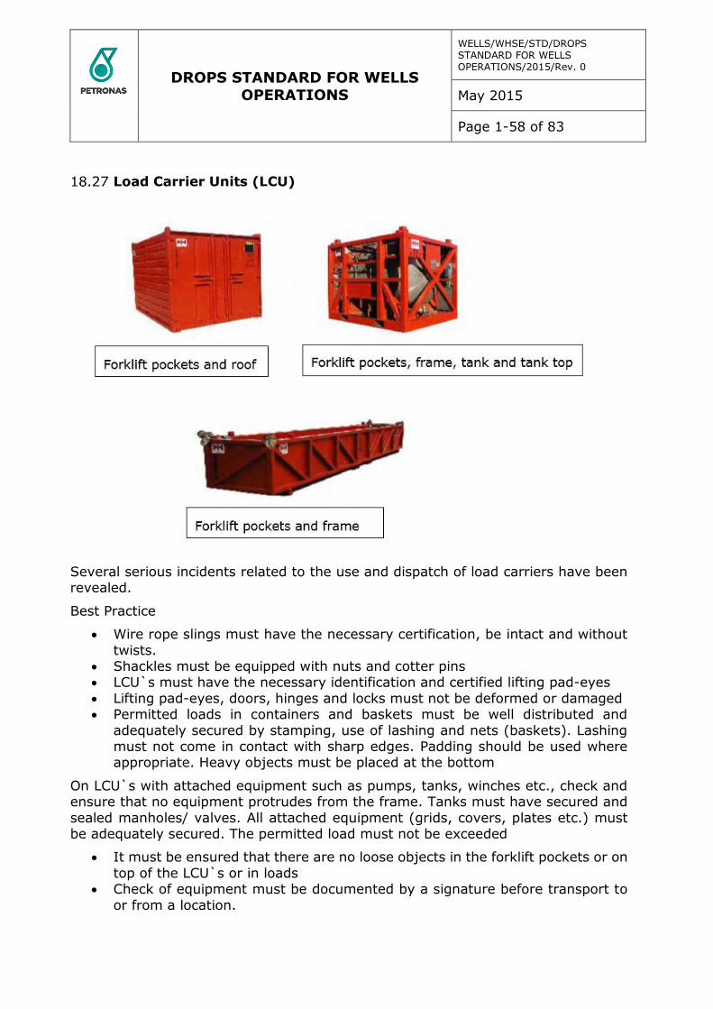
DROPS STANDARD FOR WELLS OPERATIONS
WELLS/WHSE/STD/DROPS STANDARD FOR WELLS OPERATIONS/2015/Rev. 0
May 2015
Page 1-58 of 83
Load Carrier Units (LCU)
Several serious incidents related to the use and dispatch of load carriers have been revealed.
Best Practice
Wire rope slings must have the necessary certification, be intact and without
twists. Shackles must be equipped with nuts and cotter pins LCU`s must have the necessary identification and certified lifting pad-eyes
Lifting pad-eyes, doors, hinges and locks must not be deformed or damaged Permitted loads in containers and baskets must be well distributed and
adequately secured by stamping, use of lashing and nets (baskets). Lashing must not come in contact with sharp edges. Padding should be used where appropriate. Heavy objects must be placed at the bottom
On LCU`s with attached equipment such as pumps, tanks, winches etc., check and ensure that no equipment protrudes from the frame. Tanks must have secured and
sealed manholes/ valves. All attached equipment (grids, covers, plates etc.) must be adequately secured. The permitted load must not be exceeded
It must be ensured that there are no loose objects in the forklift pockets or on
top of the LCU`s or in loads Check of equipment must be documented by a signature before transport to
or from a location.

DROPS STANDARD FOR WELLS OPERATIONS
WELLS/WHSE/STD/DROPS STANDARD FOR WELLS OPERATIONS/2015/Rev. 0
May 2015
Page 1-59 of 83
Correct use of shackles
Illustration for shackles > WLL 8.5 t. on small shackles, the load must be distributed across the whole bolt. Example: if a load of WLL 10.5 t is distributed across only 40
per cent of the shackle bolt’s length, WLL is reduced to 10.5 x 0.8 = 8.4 t.
Best practice
Shackles must be certified, CE-marked and approved, i.e. be marked with the designated colour code of the year.
Shackles must be equipped with two barriers: nut and cotter pin
Shackles must only be used for their intended purpose and manner The user must be familiar with the applicable limitations and guidelines for
use Shackles are designed to support the load at the bottom of the hollow torus
and evenly across the shackle bolt
If shackles are exposed to loads in other places, this must be taken into account during use as it will reduce capacity
Point loads on the shackle bolt should be kept to a minimum as it will reduce capacity
On shackles with a capacity of more than 8.5 t, or have large openings, the
reduction factor shown at the bottom of the figure may be used to prevent deformation of the shackle bolt.
DROPS STANDARD FOR WELLS OPERATIONS
WELLS/WHSE/STD/DROPS STANDARD FOR WELLS OPERATIONS/2015/Rev. 0
May 2015
Page 1-60 of 83
Correct use of eye-bolts / eye-nuts
Before use of grade 80 eye bolts, see designated lifting table.
Figure showing correctly and incorrectly installed eye bolts; note: only grade 80 (or
better) eye bolts shall be used offshore.
Best practice
Eye bolts / eye nuts must be certified, CE-marked and approved, i.e. be marked with the designated colour code of the year (preferably by using coloured tie wraps)
Eye bolts / nuts must only be used for their intended purpose and manner The user must be familiar with the applicable limitations and guidelines for
use Eye bolts / nuts for use offshore shall be at least grade 80 Eye bolts / nuts for
use onshore should be at least grade 80
Grade 80 eye bolts / nuts are labelled with the permitted load in the least advantageous direction, i.e. 90 degrees on the fastening bolt
Eye bolts / nuts must be adequately tightened prior to use Manufacturer installed eye bolts / nuts are normally appropriate for use during
installation/removal of the units they are installed on, e.g. gear boxes, pumps,
motors and valves Eye bolts / nuts must be removed after use, and the threads in the equipment
on which they have been used must be preserved by for example; grease and a plastic plug.
DROPS STANDARD FOR WELLS OPERATIONS
WELLS/WHSE/STD/DROPS STANDARD FOR WELLS OPERATIONS/2015/Rev. 0
May 2015
Page 1-61 of 83
19 Storage Area
The unit Owner is to create a sacked storage GA drawing indicating the layout, access/ escape routes, allowable floor loading and maximum limitations of main
storage areas of sacked and palleted material. The drawing shall show the method, arrangement and maximum stacking heights of materials. It will also indicate the
limitations and working areas for forklifts, pallet loaders or other forms of lifting and transportation and will be prominently displayed in the main storage areas, and in other areas where sacks and pallets are routinely stored.
Temporary storage areas for sacks or palleted material shall in all instances, have specific risk assessments performed with procedures and limitations clearly
displayed in the respective area.
Stacks shall not be built within 450mm of a wall (bulkhead), unless designed to support the pressure of the stacked material.
Material of differing sizes and shapes shall not be stacked on top of each other unless suitable precautions are taken to prevent movement or unequal
settling. Integrity and stability of pallets and palletised items shall be inspected before
being moved or lifted.
Adequate storage shelving shall be provided for storage of equipment and supplies. The shelving loading limitations, access and method of loading
shelves shall be considered in an engineering design study and shelves marked accordingly.
Forklifts shall be properly equipped to handle their intended loads (e.g. when
used for transporting tubulars they shall be equipped with an engineered clamping or securing arrangement).
The unit Owner is to provide training in the correct use of forklifts, pallet lifters and other hoisting or travelling machinery used on the unit. Records of training and qualifications shall be maintained.
The unit Owner is to ensure that only qualified crane operators and banksmen are involved with crane operations. Records of training and qualifications shall
be maintained. The warehouse supply chain has to contain processes that can identify
equipment with potential DROPS risks before delivery to the installation and
take necessary measures. Records are to be maintained and used for improvement process.
Racks and storage
The design of racks for storage of material and equipment is often not appropriate to ensure safe storage.
Best practice
Ensure that temporary storage in modules is permitted in a controlled manner with respect to type of goods, duration, storage area and house keeping
Storage must not obstruct accessibility or evacuation of the module Ensure that the stored materials do not obstruct access to emergency
equipment
DROPS STANDARD FOR WELLS OPERATIONS
WELLS/WHSE/STD/DROPS STANDARD FOR WELLS OPERATIONS/2015/Rev. 0
May 2015
Page 1-62 of 83
Storage racks and storage areas must be designed to ensure that equipment cannot accidentally drop to lower levels
The heaviest equipment should be stored lowest
On mobile units, temporary storage space / racks must be sea fastened and shelves shall be equipped with baffle plates.
Unnecessary equipment at height
Obsolete equipment is often found at height. This equipment is often excluded from
established inspection and maintenance procedures, and introduces a considerable risk potential.
Best practice
It is mandatory on regular basis to evaluate what equipment is required or should be removed.
The assessment should establish whether equipment should be relocated to reduce the risk of collision with mobile equipment
Inspection and maintenance procedures should be revised regularly, to ensure inspection and maintenance of all equipment installed at height.
Final checks must be carried out consistently to ensure that no equipment/
materials are forgotten at height
Securing of parts, equipment and material during work at height
The potential for dropped objects during repair and installation work at height is severe and is reflected in a significant proportion of reported incidents.
PETRONAS Requirement
All repair and maintenance work at height must be risk assessed
All parts, equipment and material used at height must be secured against drop Small parts must be stored in suitable storage containers or similar In limited areas, for example the derrick, flare boom and cranes, tools used
at height must be logged out and in to ensure that nothing is left behind. When the work is complete, a final check must be carried out, to ensure that
no material or equipment have been left at height.
Post inspection / final check of the work site
Always keep your work site tidy.
Best practice
Tools, equipment and material must be secured in a safe location, at the end of each shift
When the work is finished, a final check and inventory count must be carried out to ensure that no tools, equipment or material is not left behind at height
The work site must be left in a tidy and clean state, and all tools, equipment
and material must be returned to their designated storage place.

DROPS STANDARD FOR WELLS OPERATIONS
WELLS/WHSE/STD/DROPS STANDARD FOR WELLS OPERATIONS/2015/Rev. 0
May 2015
Page 1-63 of 83
Observation technique
In order to identify Potentially Dropped Objects (DO), it is important to be trained in
DO observation techniques. The training must include methods for reliable securing of equipment.
Best practice
Inspection Ample time
Limit size of the area Concentrate on a small number of categories and inspect in a structured way
to maintain an overview Limit number of personnel in each area, to keep an overview Findings not in conformity with the established standard or checklist are
photographed, given an accurate description and site reference Inspection, identification and categorization of findings are the first steps in minimizing
the potential for dropped objects Follow-up and correction of findings are decisive factors in preventing dropped
objects
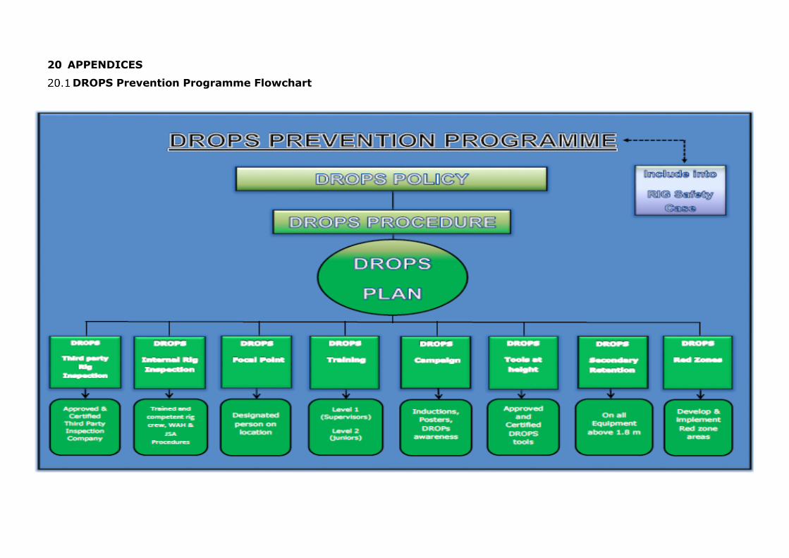
20 APPENDICES
DROPS Prevention Programme Flowchart
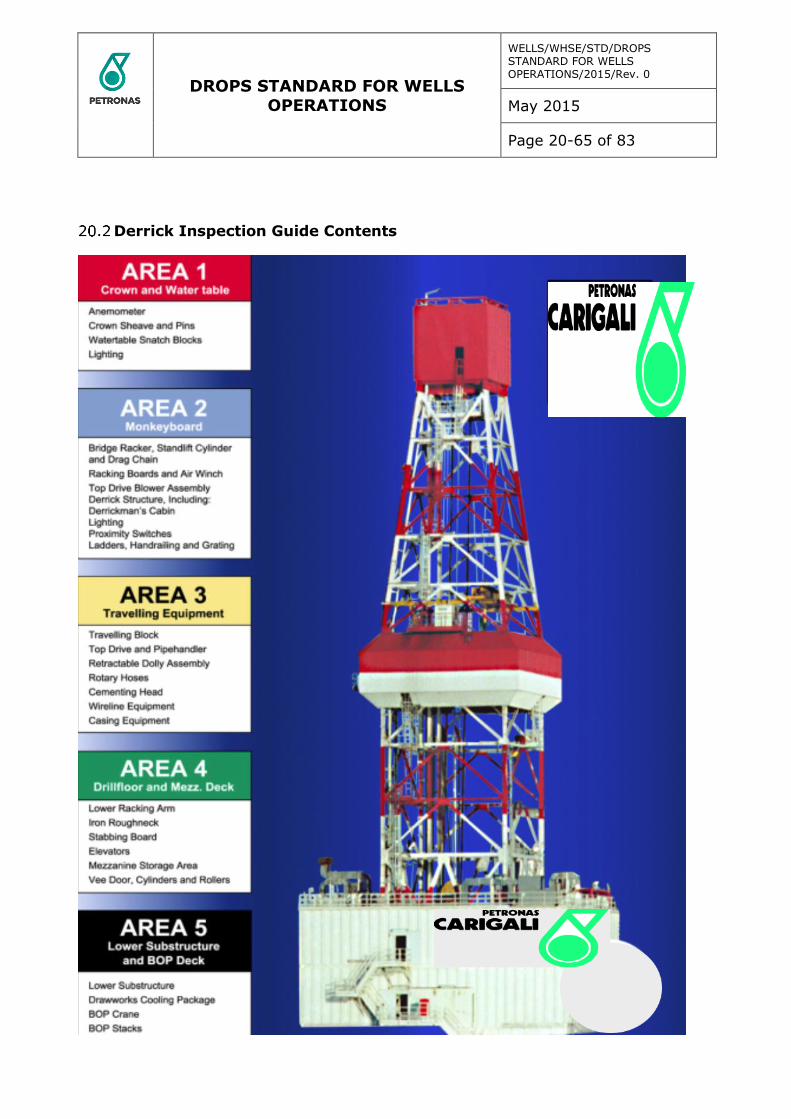
DROPS STANDARD FOR WELLS OPERATIONS
WELLS/WHSE/STD/DROPS STANDARD FOR WELLS OPERATIONS/2015/Rev. 0
May 2015
Page 20-65 of 83
Derrick Inspection Guide Contents
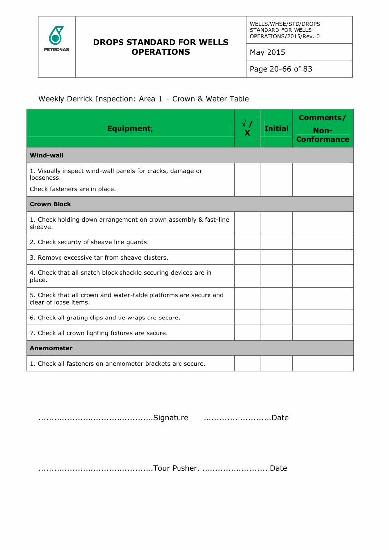
DROPS STANDARD FOR WELLS OPERATIONS
WELLS/WHSE/STD/DROPS STANDARD FOR WELLS OPERATIONS/2015/Rev. 0
May 2015
Page 20-66 of 83
Weekly Derrick Inspection: Area 1 – Crown & Water Table
Equipment; / X
Initial
Comments/
Non-Conformance
Wind-wall
1. Visually inspect wind-wall panels for cracks, damage or looseness.
Check fasteners are in place.
Crown Block
1. Check holding down arrangement on crown assembly & fast-line sheave.
2. Check security of sheave line guards.
3. Remove excessive tar from sheave clusters.
4. Check that all snatch block shackle securing devices are in place.
5. Check that all crown and water-table platforms are secure and clear of loose items.
6. Check all grating clips and tie wraps are secure.
7. Check all crown lighting fixtures are secure.
Anemometer
1. Check all fasteners on anemometer brackets are secure.
............................................Signature ..........................Date
............................................Tour Pusher. ..........................Date

DROPS STANDARD FOR WELLS OPERATIONS
WELLS/WHSE/STD/DROPS STANDARD FOR WELLS OPERATIONS/2015/Rev. 0
May 2015
Page 20-67 of 83
Weekly Derrick Inspection: Area 2 – Monkeyboard
Equipment / X Initial
Comments/
Non-Conformance
Bridge Racker
1. Check fastenings on traverse motor and bracket.
2. Visually check fastenings on slew motor
3. Check fastenings on long travel cylinders
4. Check fasteners on wire guide
5. Check roller assemblies on racker head
6. Check fasteners on claw assembly and claw motor
7. Check springs on anti-fall device.
Stand lift Cylinder
1. Visually inspect fasteners on mounting brackets
2. Visually inspect fasteners on support bracket and sheave
3. Check hoist wire and swivels
Drag Chain
1. Check tie rod fasteners and seizing wire
2. Check fasteners on troughs.
Racking Boards
Monkey-board
1. Check condition of derrick-mans belt.
Racking Boards
1. Check fasteners, pins and safety wires on drill-pipe latches.
2. Check fasteners, pins and safety wires on drill collar latches
3. Check pins, cotters and safety wire on kick flap
Air Winch
1. Check winch holding down bolts
2. Check wire rope, chain shackle and hook
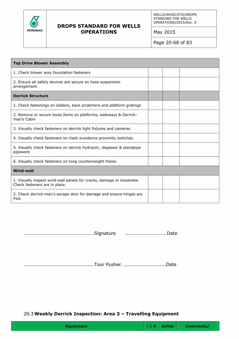
DROPS STANDARD FOR WELLS OPERATIONS
WELLS/WHSE/STD/DROPS STANDARD FOR WELLS OPERATIONS/2015/Rev. 0
May 2015
Page 20-68 of 83
Top Drive Blower Assembly
1. Check blower assy foundation fasteners
2. Ensure all safety devices are secure on hose suspension arrangement.
Derrick Structure
1. Check fastenings on ladders, back scratchers and platform gratings
2. Remove or secure loose items on platforms, walkways & Derrick-
man’s Cabin
3. Visually check fasteners on derrick light fixtures and cameras.
4. Visually check fasteners on clash avoidance proximity switches.
5. Visually check fasteners on derrick hydraulic, degasser & standpipe pipework
6. Visually check fasteners on tong counterweight frame.
Wind-wall
1. Visually inspect wind-wall panels for cracks, damage or looseness. Check fasteners are in place.
2. Check derrick-man’s escape door for damage and ensure hinges are free.
............................................Signature ..........................Date
............................................Tour Pusher. ..........................Date
Weekly Derrick Inspection: Area 3 – Travelling Equipment
Equipment; / X Initial Comments/

DROPS STANDARD FOR WELLS OPERATIONS
WELLS/WHSE/STD/DROPS STANDARD FOR WELLS OPERATIONS/2015/Rev. 0
May 2015
Page 20-69 of 83
Non-Conformance
Travelling Block
1. Check side plate fasteners
2. Check integrity of locking device on clevis.
3. Check security of hang-off line shackle pin.
Top Drive & Pipe-handler
Top Drive
1. Check locking arrgmt on compensator cylinder shackles.
2. Check safety chains & shackles on service loops.
3. Check safety sling on lub.oil pump.
Pipe-handler
1. Check link hanger supports
2. Check link block bolts
3. Check IBOP cylinder clevis
4. Check IBOP actuating rollers
5. Check IBOP sleeve & crank assy.
6. Check torque wrench guide rods & pins
7. Check guide rod clamps
8. Check torque wrench cyl. end plate fasteners
9. Check centralizing spring safety wires
10. Check lower bell guide bolts & safety sling
11. Check torque wrench clamp bolts
Retractable Dolly Assembly
1. Check dolly side rollers & axles
2. Check bogie wheels & keeper plates
3. Check dolly arm attachments
4. Check dolly position sensor brackets
Rotary Hoses
1. Check clamp bolts

DROPS STANDARD FOR WELLS OPERATIONS
WELLS/WHSE/STD/DROPS STANDARD FOR WELLS OPERATIONS/2015/Rev. 0
May 2015
Page 20-70 of 83
2. Check safety chains and shackles
3. Check security of lifting clamp
Cementing Head
1. Check lifting bridle shackles. Ensure cotter pins are in place.
2. Check lock pin arrangement is secure.
Wire-line Equipment
1. Check SDC sheave is locked by castle nut c/w split pin.
2. Check SDC shackles and lifting spade are suitably locked off with Tie-wraps.
Casing Equipment
1. Check fasteners, slings and shackles on the following tubular handling equipment:
1. Loadmaster
2. Single Joint Elevators
3. Side Door Elevators
4. HYC & YC Elevators
5. 350 ton & 500 ton Varco Elevators
6. Spring Hanger and Lift Cylinder
2. Check fasteners on casing spinner are secure and suitably locked off
............................................Signature ..........................Date
............................................Tour Pusher. ..........................Date
Weekly Derrick Inspection: Area 4 – Drill floor & Mezzanine Deck
Equipment /
X Initial
Comments/
Non-
Conformance
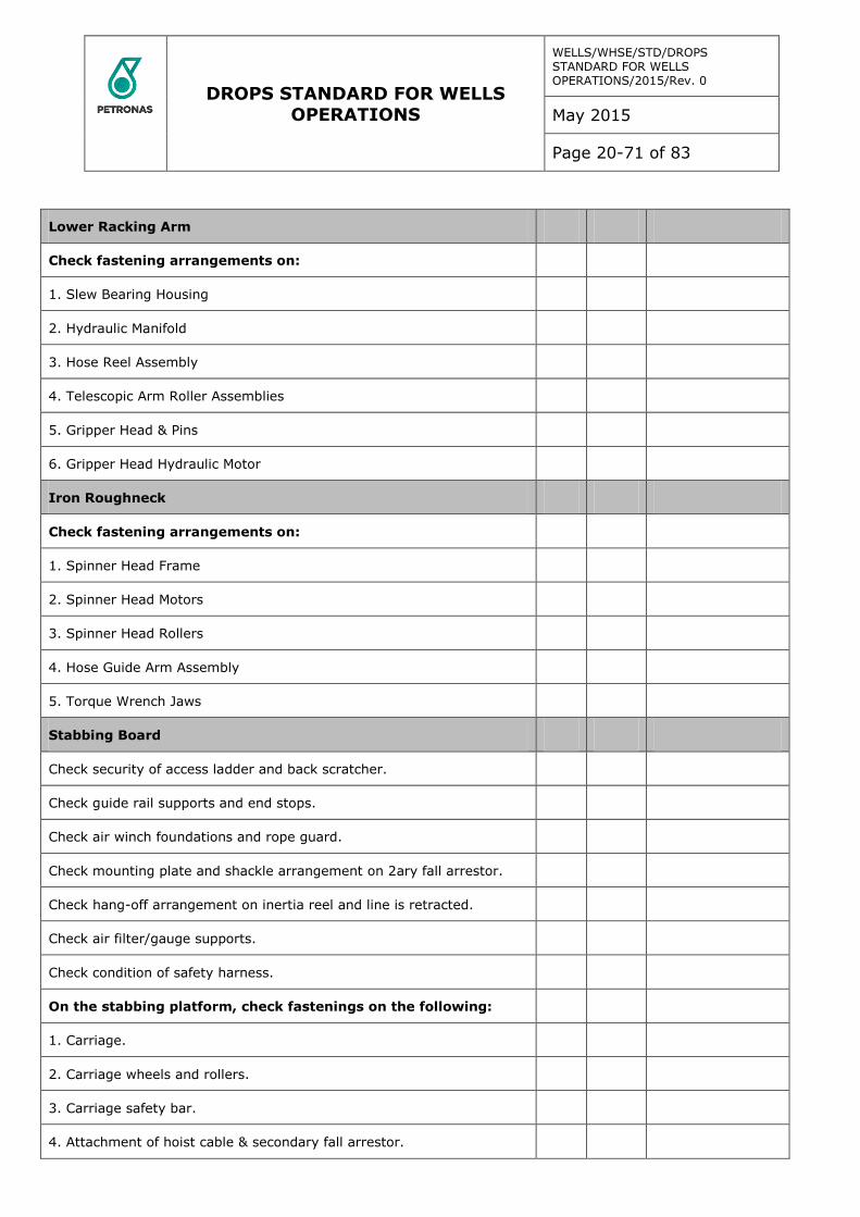
DROPS STANDARD FOR WELLS OPERATIONS
WELLS/WHSE/STD/DROPS STANDARD FOR WELLS OPERATIONS/2015/Rev. 0
May 2015
Page 20-71 of 83
Lower Racking Arm
Check fastening arrangements on:
1. Slew Bearing Housing
2. Hydraulic Manifold
3. Hose Reel Assembly
4. Telescopic Arm Roller Assemblies
5. Gripper Head & Pins
6. Gripper Head Hydraulic Motor
Iron Roughneck
Check fastening arrangements on:
1. Spinner Head Frame
2. Spinner Head Motors
3. Spinner Head Rollers
4. Hose Guide Arm Assembly
5. Torque Wrench Jaws
Stabbing Board
Check security of access ladder and back scratcher.
Check guide rail supports and end stops.
Check air winch foundations and rope guard.
Check mounting plate and shackle arrangement on 2ary fall arrestor.
Check hang-off arrangement on inertia reel and line is retracted.
Check air filter/gauge supports.
Check condition of safety harness.
On the stabbing platform, check fastenings on the following:
1. Carriage.
2. Carriage wheels and rollers.
3. Carriage safety bar.
4. Attachment of hoist cable & secondary fall arrestor.
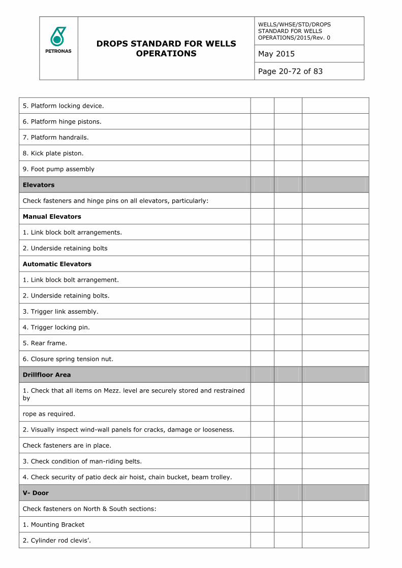
DROPS STANDARD FOR WELLS OPERATIONS
WELLS/WHSE/STD/DROPS STANDARD FOR WELLS OPERATIONS/2015/Rev. 0
May 2015
Page 20-72 of 83
5. Platform locking device.
6. Platform hinge pistons.
7. Platform handrails.
8. Kick plate piston.
9. Foot pump assembly
Elevators
Check fasteners and hinge pins on all elevators, particularly:
Manual Elevators
1. Link block bolt arrangements.
2. Underside retaining bolts
Automatic Elevators
1. Link block bolt arrangement.
2. Underside retaining bolts.
3. Trigger link assembly.
4. Trigger locking pin.
5. Rear frame.
6. Closure spring tension nut.
Drillfloor Area
1. Check that all items on Mezz. level are securely stored and restrained
by
rope as required.
2. Visually inspect wind-wall panels for cracks, damage or looseness.
Check fasteners are in place.
3. Check condition of man-riding belts.
4. Check security of patio deck air hoist, chain bucket, beam trolley.
V- Door
Check fasteners on North & South sections:
1. Mounting Bracket
2. Cylinder rod clevis’.
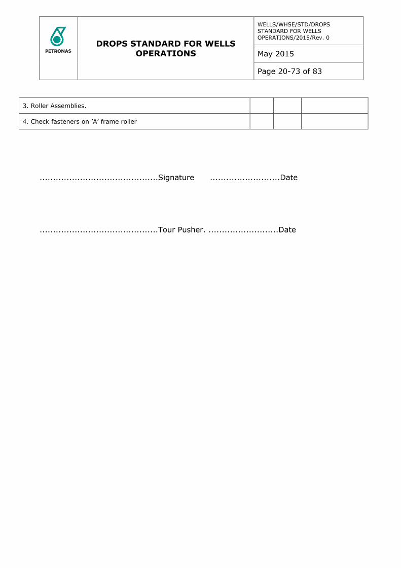
DROPS STANDARD FOR WELLS OPERATIONS
WELLS/WHSE/STD/DROPS STANDARD FOR WELLS OPERATIONS/2015/Rev. 0
May 2015
Page 20-73 of 83
3. Roller Assemblies.
4. Check fasteners on ’A’ frame roller
............................................Signature ..........................Date
............................................Tour Pusher. ..........................Date
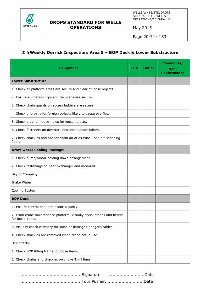
DROPS STANDARD FOR WELLS OPERATIONS
WELLS/WHSE/STD/DROPS STANDARD FOR WELLS OPERATIONS/2015/Rev. 0
May 2015
Page 20-74 of 83
Weekly Derrick Inspection: Area 5 – BOP Deck & Lower Substructure
Equipment / X Initial
Comments/
Non-Conformance
Lower Substructure
1. Check all platform areas are secure and clear of loose objects.
2. Ensure all grating clips and tie wraps are secure.
3. Check chain guards on access ladders are secure.
4. Check drip pans for foreign objects likely to cause overflow.
5. Check around mouse-holes for loose objects.
6. Check fasteners on diverter lines and support rollers.
7. Check shackles and anchor chain on Atlas Wire-line Unit under rig floor.
Draw-works Cooling Package:
1. Check pump/motor holding down arrangement.
2. Check fastenings on heat exchanger and monorail.
Baylor Company
Brake Water
Cooling System.
BOP Deck
1. Ensure control pendant is stored safely.
2. From crane maintenance platform, visually check cranes and beams for loose items.
3. Visually check catenary for loose or damaged hangers/cables.
4. Check shackles are removed when crane not in use.
BOP Stacks
1. Check BOP lifting frame for loose items.
2. Check chains and shackles on choke & kill lines.
............................................Signature ..........................Date
............................................Tour Pusher. ..........................Date
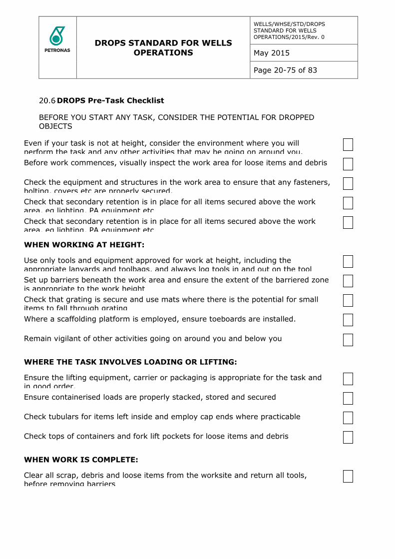
DROPS STANDARD FOR WELLS OPERATIONS
WELLS/WHSE/STD/DROPS STANDARD FOR WELLS OPERATIONS/2015/Rev. 0
May 2015
Page 20-75 of 83
DROPS Pre-Task Checklist
BEFORE YOU START ANY TASK, CONSIDER THE POTENTIAL FOR DROPPED OBJECTS
Even if your task is not at height, consider the environment where you will perform the task and any other activities that may be going on around you.
Before work commences, visually inspect the work area for loose items and debris
Check the equipment and structures in the work area to ensure that any fasteners, bolting, covers etc are properly secured.
Check that secondary retention is in place for all items secured above the work area, eg lighting, PA equipment etc
Check that secondary retention is in place for all items secured above the work area, eg lighting, PA equipment etc
WHEN WORKING AT HEIGHT:
Use only tools and equipment approved for work at height, including the appropriate lanyards and toolbags, and always log tools in and out on the tool
register
Set up barriers beneath the work area and ensure the extent of the barriered zone is appropriate to the work height
Check that grating is secure and use mats where there is the potential for small items to fall through grating
Where a scaffolding platform is employed, ensure toeboards are installed.
Remain vigilant of other activities going on around you and below you
WHERE THE TASK INVOLVES LOADING OR LIFTING:
Ensure the lifting equipment, carrier or packaging is appropriate for the task and in good order.
Ensure containerised loads are properly stacked, stored and secured
Check tubulars for items left inside and employ cap ends where practicable
Check tops of containers and fork lift pockets for loose items and debris
WHEN WORK IS COMPLETE:
Clear all scrap, debris and loose items from the worksite and return all tools, before removing barriers
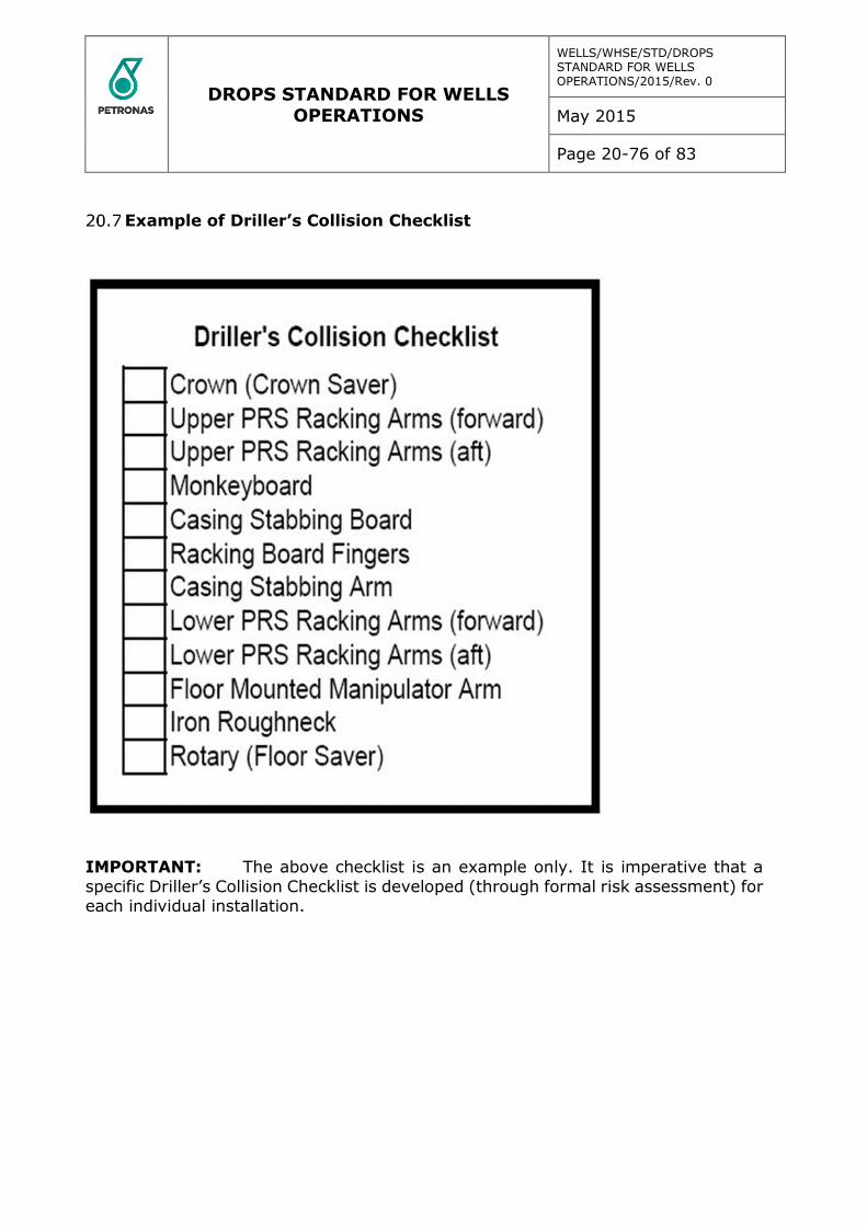
DROPS STANDARD FOR WELLS OPERATIONS
WELLS/WHSE/STD/DROPS STANDARD FOR WELLS OPERATIONS/2015/Rev. 0
May 2015
Page 20-76 of 83
Example of Driller’s Collision Checklist
IMPORTANT: The above checklist is an example only. It is imperative that a
specific Driller’s Collision Checklist is developed (through formal risk assessment) for each individual installation.
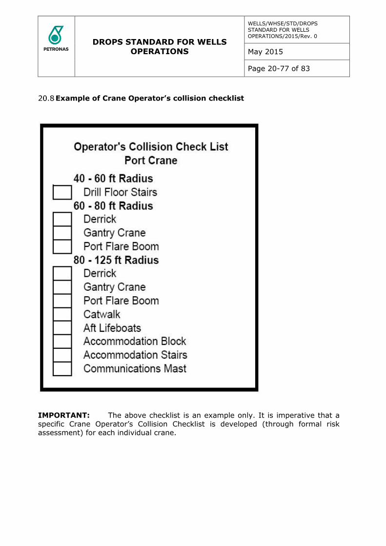
DROPS STANDARD FOR WELLS OPERATIONS
WELLS/WHSE/STD/DROPS STANDARD FOR WELLS OPERATIONS/2015/Rev. 0
May 2015
Page 20-77 of 83
Example of Crane Operator’s collision checklist
IMPORTANT: The above checklist is an example only. It is imperative that a
specific Crane Operator’s Collision Checklist is developed (through formal risk assessment) for each individual crane.
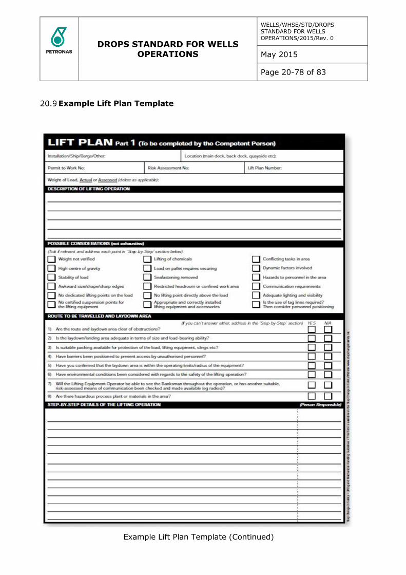
DROPS STANDARD FOR WELLS OPERATIONS
WELLS/WHSE/STD/DROPS STANDARD FOR WELLS OPERATIONS/2015/Rev. 0
May 2015
Page 20-78 of 83
Example Lift Plan Template
Example Lift Plan Template (Continued)

DROPS STANDARD FOR WELLS OPERATIONS
WELLS/WHSE/STD/DROPS STANDARD FOR WELLS OPERATIONS/2015/Rev. 0
May 2015
Page 20-79 of 83
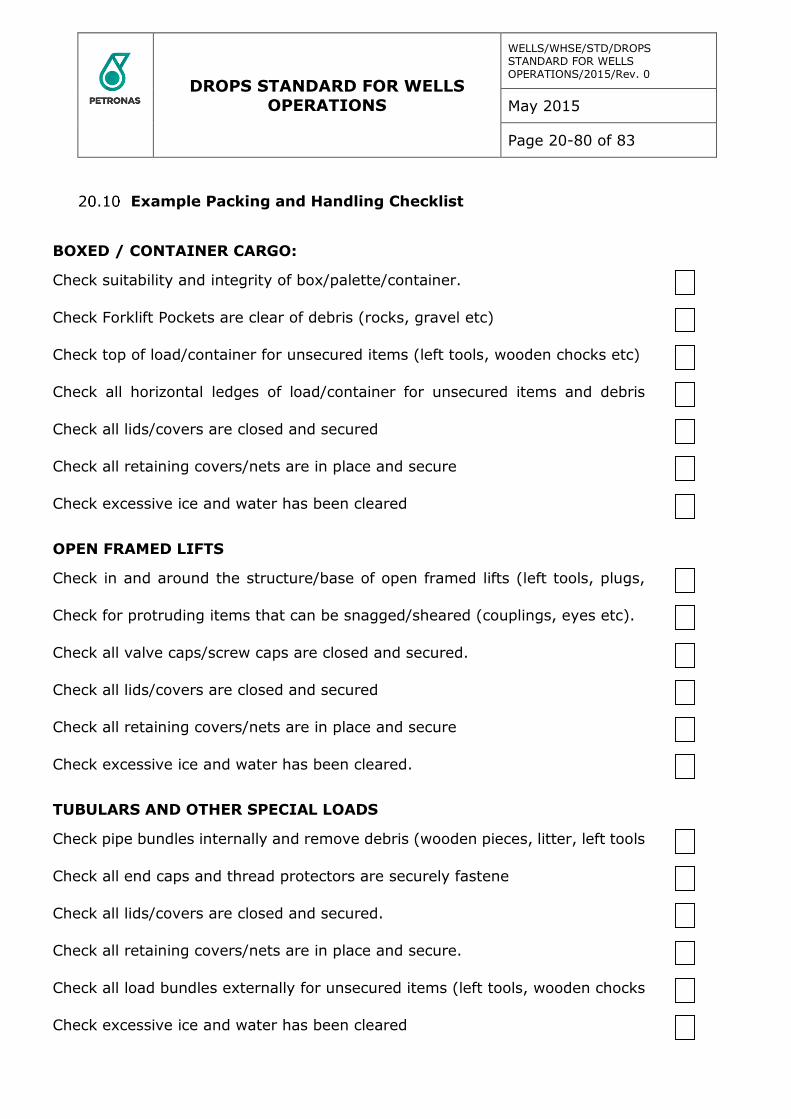
DROPS STANDARD FOR WELLS OPERATIONS
WELLS/WHSE/STD/DROPS STANDARD FOR WELLS OPERATIONS/2015/Rev. 0
May 2015
Page 20-80 of 83
Example Packing and Handling Checklist
BOXED / CONTAINER CARGO:
Check suitability and integrity of box/palette/container.
Check Forklift Pockets are clear of debris (rocks, gravel etc)
Check top of load/container for unsecured items (left tools, wooden chocks etc)
Check all horizontal ledges of load/container for unsecured items and debris
(wood, litter, tools etc)
Check all lids/covers are closed and secured
Check all retaining covers/nets are in place and secure
Check excessive ice and water has been cleared
OPEN FRAMED LIFTS
Check in and around the structure/base of open framed lifts (left tools, plugs,
litter etc)
Check for protruding items that can be snagged/sheared (couplings, eyes etc).
Check all valve caps/screw caps are closed and secured.
Check all lids/covers are closed and secured
Check all retaining covers/nets are in place and secure
Check excessive ice and water has been cleared.
TUBULARS AND OTHER SPECIAL LOADS
Check pipe bundles internally and remove debris (wooden pieces, litter, left tools
etc).
Check all end caps and thread protectors are securely fastene
Check all lids/covers are closed and secured.
Check all retaining covers/nets are in place and secure.
Check all load bundles externally for unsecured items (left tools, wooden chocks
etc)
Check excessive ice and water has been cleared
DROPS STANDARD FOR WELLS OPERATIONS
WELLS/WHSE/STD/DROPS STANDARD FOR WELLS OPERATIONS/2015/Rev. 0
May 2015
Page 20-81 of 83
NOTES:
1. Additional checks to be carried out by truck drivers, crane operators, ships masters etc in accordance with industry standards to ensure all cargo freight is
properly secured during transit.
2. Prior to carrying out any lifting operations, always refer to documented
procedures for routine lifts or the lifting plan and associated risk assessment for non-routine activities.
3. Checks must always be carried out in accordance with industry standards to
ensure all lifting equipment is certified for current use, restrictions and fastenings are removed, effective communication systems are in place and there is adequate
light and space to undertake the activity.
4 A toolbox talk will be held before any lifting operation to discuss the task in detail and identify all potential hazards and mitigate the risks, including the
potential for dropped objects controls.
DROPS STANDARD FOR WELLS OPERATIONS
WELLS/WHSE/STD/DROPS STANDARD FOR WELLS OPERATIONS/2015/Rev. 0
May 2015
Page 20-82 of 83
Glossary of Terms and Abbreviations
DEFINITIONS
At height is defined as: one point eight (1.8) meters and above, or with the
potential to drop two one point eight (1.8) or more. However, due consideration is required to be given to objects which are located at a lower height but have an
increased potential to drop (e.g. items on a workbench or on lower shelves).
Dropped Object means any item or object (including persons) that falls from its previous position.
Dynamic dropped object means any object that falls from its previous position due to an applied force.
Static dropped object means any object that falls from its previous position under its own weight (gravity) without any applied force.
Dropped Objects Standard (DROPS) means the Petronas Carigali standard for
the Safe Operation of Offshore Installations in respect of Dropped Objects prevention
Equipment means any installed equipment or component, permanent or temporary, which is not an integral part of the structure.
Major non-conformity means an identifiable deviation that poses a serious threat
to the safety of personnel or the installation or a serious risk to the environment that requires immediate corrective action or the lack of effective and systematic
implementation of a requirement of this Standard.
Non-conformity means an observed non-fulfilment of a specified requirement.
Person in Charge (PIC) is the designated individual in charge of the dropped
object prevention on the unit; this can be the OIM, barge master, captain or toolpusher as designated by the unit Owner.
Primary fixing means the primary method by which an item is installed, mounted and secured as to prevent the item from falling (e.g. bolt, nut, weld).
Safety management system (SMS) means a structured and documented
system enabling Company personnel to implement effectively the Company safety and environmental protection policy.
Secondary retention means the engineered method for securing the primary fixing to prevent loss of pre-load or displacement of fastening components (e.g. lock washer, lock wire, safety pin).
Secondary securing means the additional engineered method to secure the item to the structure, designed to restrain the item should the primary fixing fail (e.g.
safety sling, safety net).
Structure means any manufactured assembly that has been designed and
engineered to be integral to the unit.
Third party equipment means any equipment not belonging to the unit Owner. It can be rented or borrowed equipment, installed permanently or temporarily.
Unit Owner means the owner of the asset.
DROPS STANDARD FOR WELLS OPERATIONS
WELLS/WHSE/STD/DROPS STANDARD FOR WELLS OPERATIONS/2015/Rev. 0
May 2015
Page 20-83 of 83
ABBREVIATIONS
FEM – Finite Element Method
GA – General arrangement
ID – Identification
PCSB – Petronas Carigali Sn Bn
MOC – Management of Change
OEM – Original Equipment Manufacturer
PIC – Person in Charge
PPE – Personal Protective Equipment
SMS – Safety Management System
SWL – Safe Working Load
![ENVIRONMENTAL PROTECTION COMMISSION[567] · 2014-06-25 · wells, recreational-use wells, monitoring wells, heat pump supply wells or GHEX loop boreholes, industrial wells, and dewatering](https://cdn.vdocuments.net/doc/165x107/5f3f728939b254613866ae00/environmental-protection-commission567-2014-06-25-wells-recreational-use-wells.jpg)


