
1
DS-7200HVI-ST Series DVR
USER’S MANUAL
Version 1.0

2
Hikvision® Network Digital Video Recorder User Guide
Copyright © 2010, Hikvision, Ltd. All rights reserved.
This document may not be copied in whole or in part or otherwise reproduced withoutprior
written consent from Hikvision except where specifically permitted under US andinternational
copyright law. The information in this document is subject to change without notice. Hikvision
assumes no responsibility or liability for any errors or inaccuracies that may appear in this book.
This manual is written for DVR firmware version 1.0.

3
Preventive and Cautionary Tips
Before connecting and operating your DVR, please be advised of the following tips: • Ensure unit is installed in a well-ventilated, dust-free environment. • Unit is designed for indoor use only. • Keep all liquids away from the DVR. • Ensure environmental conditions meet factory specifications. • Ensure unit is properly secured to a rack or shelf. Major shocks or jolts to the unit as a result of dropping it may cause
damage to the sensitive electronics within the unit. • Use the DVR in conjunction with an UPS if possible. • Power down the unit before connecting and disconnecting accessories and peripherals. • A factory recommended HDD should be used for this device. • Improper use or replacement of the battery may result in an explosion. Replace with the same or equivalent type only.
Dispose of used batteries according to the instructions provided by the battery manufacturer.
4
TABLE OF CONTENTS
Contents C H A P T E R 1Introduction .............................................................................................................. 7
1.1 Overview ............................................................................................................................................. 8
1.1.1 Product Key Features ................................................................................................................... 8
1.2 Connecting Your DVR ..................................................................................................................... 10
1.3 Operating Your DVR .......................................................................................................................... 11
1.3.1 Using the Front Panel Controls .................................................................................................. 11
1.4 Using the IR Remote Control............................................................................................................. 13
1.5 Using a USB Mouse ........................................................................................................................... 14
1.6 Using the Soft Keyboard ................................................................................................................... 15
C H A P T E R 2 Getting Started ........................................................................................................... 16
2.1 Starting and Shutting Down Your DVR .............................................................................................. 16
2.2 Rebooting and Locking Your DVR ...................................................................................................... 17
2.3 Setting Date & Time .......................................................................................................................... 17
2.4 Checking the Status of Your DVR ...................................................................................................... 19
C H A P T E R 3 Live Feed .................................................................................................................... 20
3.1 Watching a Live Feed ........................................................................................................................ 20
3.1.1 Understanding Live Feed Icons .................................................................................................. 20
3.1.2Operating the Live Feed .............................................................................................................. 21
3.2 Using the Display Menu .................................................................................................................... 23
3.3 Configuring Live Feed Displays .......................................................................................................... 24
3.4 Setting Camera Order ....................................................................................................................... 25
C H A P T E R 4 Record Settings ........................................................................................................... 26
4.1 Configuring Settings for Recording ................................................................................................... 26
4.1.1 Configuring Recording Settings .................................................................................................. 26
4.1.2 Configuring a Quick Recording Schedule ................................................................................... 27
4.1.3 Configuring an Advanced Recording Schedule .......................................................................... 28
C H A P T E R 5 Playback ..................................................................................................................... 30

5
5.1 Playing Back a Recording .................................................................................................................. 30
5.1.1 Understanding the Playback Interface ....................................................................................... 30
5.2 Searching for Recorded Files ............................................................................................................. 31
5.3 Playing Back Recorded Files .............................................................................................................. 32
5.4 Playing Back Multiple Channels ........................................................................................................ 33
C H A P T E R 6 Backup ........................................................................................................................ 33
6.1 Backing Up Video Clips ...................................................................................................................... 33
6.1.1 Selecting Video Clips .................................................................................................................. 33
6.2 Backing Up Video Clips ...................................................................................................................... 34
6.3 Backing Up Recorded Files ................................................................................................................ 35
C H A P T E R 7 System Configuration .................................................................................................. 37
7.1 Configuring Network Settings ........................................................................................................... 37
7.2 Managing User Accounts .................................................................................................................. 38
7.2.1 Adding a New Remote/Local User ............................................................................................. 38
7.2.2 Deleting a User ........................................................................................................................... 39
7.2.3 Editing a User ............................................................................................................................. 40
7.2.4 Switch User ................................................................................................................................ 40
7.3 Configuring PTZ Cameras .................................................................................................................. 40
7.3.1 Configuring Basic PTZ Settings ................................................................................................... 41
7.4 Customizing PTZ Presets, Patterns and Patrols ................................................................................ 42
7.5 Configuring Alarms and Exceptions ................................................................................................. 43
7.5.1 Setting Up Motion Detection ..................................................................................................... 43
7.5.2 Configuring Alarm Inputs ........................................................................................................... 44
7.5.3 Configuring Exceptions .............................................................................................................. 45
7.5.4 Configuring E‐mail Settings ........................................................................................................ 46
C H A P T E R 8 Camera Management ................................................................................................. 47
8.1 To setup privacy zones:..................................................................................................................... 47
8.2 Configuring Video Tampering Detection .......................................................................................... 48
8.3 Configuring Video Loss Detection ..................................................................................................... 48
8.4 Configuring OSD Settings .................................................................................................................. 49
C H A P T E R 9 Disk Management ....................................................................................................... 51
9.1 Managing Disks ................................................................................................................................. 51

6
9.1.1 Checking Disk Status .................................................................................................................. 51
9.2 Formatting Disk ................................................................................................................................. 51
9.2.1 Enabling Disk Overwrite ............................................................................................................. 52
9.3 Managing Files .................................................................................................................................. 52
9.3.1 Searching for Recorded Files ...................................................................................................... 52
9.4 Locking and Unlocking Recorded Files .............................................................................................. 54
C H A P T E R 1 0 DVR Management .................................................................................................... 55
10.1 Managing System ............................................................................................................................ 55
10.1.1 Upgrading the System Firmware ............................................................................................. 55
10.1.2 Restoring Default Settings ....................................................................................................... 55
10.2 Exporting & Importing Configuration ............................................................................................. 56
10.3 Viewing System Logs ....................................................................................................................... 57
10.4 Locking and Unlocking System Menus ............................................................................................ 58

7
C H A P T E R 1 Introduction

8
1.1 Overview Thank you for your purchase of the DS‐7200HVI‐STSeries Digital Video Recorder (DVR). To getthe most out of your DVR, please read through this User’sManual thoroughly. Developed by Hikvision on the basis of the latest technology, DS‐7200HVI‐ST Series Digital Video Recorder combines the latest in advanced H.264 video encoding and decoding technologies delivering high performance rock‐solid reliability and longer recording times. DS‐7200HVI‐ST Digital Video Recorder can be used as a standalone video surveillance product, as well as to build up a powerful surveillance network making it is perfect for home or small business applications.
Figure 1.DS-7204HVI-ST DVR
Figure 2. DS-7208HVI-ST DVR
Figure 3. DS-7216HVI-ST DVR
1.1.1 Product Key Features
Compression
PAL/NTSC adaptive video inputs. H.264 video compression with high reliability and superior definition. OggVorbis audio compression standard. Independent video encoding parameters, including frame rate, resolution, bit rate, video quality, etc. Scheduled and event recording parameters configurable for per individual camera. Support dual stream. Encoding for both audio/video composite stream and video stream; audio and video synchronization during composite
stream encoding. Compression, storage and network transmission of 4CIF or CIF video image in JPEG format.
Local Monitoring
Up to 1024×768 resolution for VGA output display. Simultaneous VGA and CVBS output.

9
1/4-camera video live view, with the camera order adjustable. Group switch, manual switch and automatic cycle modes selectable for video live view, with the auto cycle period
configurable. Digital zoom in live view mode. Shield of assigned channel for live view. Privacy masking capability. Multiple PTZ protocols supported, and settings and callup of presets, patrols and patterns. Video image zoom-in by clicking the mouse and tracing by dragging mouse in PTZ control mode.
Hard Disk Management
Connection to 1 SATA hard disk supported, with up to 2TB storage capacity. S.M.A.R.T technology. HDD standby function. HDD file system is compatible with Windows. Use pre-allocating hard disk management technology, and no disk
fragments.
Recording Cycle and non-cycle recording mode. Scheduled and event video encoding parameters. Multiple recording types, including manual, continuous, alarm, motion, motion | alarm and motion & alarm recording, etc. 8 recording time periods with separate recording types. Pre-record and Post-record time for alarm and motion detection, and pre-record time for schedule and manual recording. Lock and unlock of video files. HDD property can be set to read-only. Video data search and playback by channel number, recording type, time etc. Digital zoom function in playback mode. Pause, play fast, play slow, skip forward, and skip backward when playback, locating in progress bar by dragging the
mouse. 4-channel synchronous playback.
Backup
Record files backed up via USB device. Bunch backup by file or by time. Record files edited for backup in playback. Management and maintenance for backup devices.
Alarm & Exception
Configurable arming time for alarm in/out. Various alarm types supported: alarms for video loss, motion detection, video tempering, video signal abnormal, video
in/out format unmatched, illegal access, network disconnection, IP conflict, hard disk error and hard disk full. Various alarm response actions supported: camera recording, relay out, on-screen warning, audible warning and upload to
center, etc. Auto recovery from exceptions.
Others Control of DVR via front panel keys, mouse, IR control and special keyboard. Three-level user management, each user with individual operating permission for DVR and camera. Powerful record and search for log of operation, alarm and exceptions. Import/export of device configuration files.
Network
10/100M adaptive network interface. TCP/IP protocol suites, PPPoE, DHCP, DNS, DDNS, NTP, SADP protocols, etc. Unicast and multicast supported; TCP and UDP protocols applicable in unicast transmission. Remote search, playback and download, lock/unlock of video files; Support breakpoint resume. Remote access and configuration of parameters; remote import/export of device configuration parameters. Remote access of device running status, system log and alarm status. Remote control of DVR via button operation. Remote lock/unlock of panel buttons and mouse. Remote formatting of hard disk, upgrade, reboot/shutdown and other system maintenance operations. RS-232 and RS -485 transparent channel transmission. Event alarm and exceptions upload to remote management host.

10
Remote manual recording. Remote video image capture in JPEG format. Remote PTZ control. Voice talk and broadcast. Built-in WEB Server.
Development
Provision of SDK in Windows and Linux operating systems. Application software source code of Demo. Support and training service for application system development.
1.2 Connecting Your DVR You may follow the diagram below (Figure 4) in connecting your DVR to its peripherals.
Figure 4. DVR Connection Diagram

11
1.3 Operating Your DVR There are numerous ways to navigate and operate your DVR. You may use the FrontPanel Controls, the included IR (Infra-Red) Remote, a Mouse and the Soft-Keyboard.
1.3.1 Using the Front Panel Controls Your DVR comes with built‐in front panel controls, as shown in Figure 5.
Figure 5. DVR Front Panel Controls
The controls on the front panel includes: 1. Status Indicators: Status indicators for different features of the DVR.
• Power: Power indicator turns green when DVR is powered on. • Status: The indicator lights when the compound key switches to numeric/letter input mode. • TX/RX: TX/RX indictor blinks blue when network connection is functioning properly.
2. IR Receiver: Receiver for IR remote. 3. Compound Buttons:
• 1 MENU: (1) Enter numeral “1”; (2) Enter the main menu interface • 2ABC/F1: (1) Enter numeral “2”; (2) Enter letters “ABC”; (3) The F1 button when used in a list field will select
all items on the list. In PTZ Control mode, it will turn on/off PTZ light. • 3DEF/F2: (1) Enter numeral “3”; (2) Enter letters “DEF”; (3) The F2 button is used to cycle through tab pages. It
will also bring up the Channel & OSD Position settings. • 4GHI/ESC: (1) Enter numeral “4”; (2) Enter letters “GHI” • (3) Exit and back to the previous menu • 5JKL/EDIT: (1) Enter numeral “5”; (2) Enter letters “JKL”; (3) Delete characters before cursor; • (4)Select the checkbox and ON/OFF switch; (5) Start/stop record clipping in playback • 6MNO/PLAY: (1) Enter numeral “6”; (2) Enter letters “MNO”; • (3) Playback, for direct access to playback interface • 7PQRS/REC: (1) Enter numeral “7”; (2) Enter letters “PQRS”; (3) Manual record, for direct access to manual
record interface; manually enable/disable record • 8TUV/PTZ: (1) Enter numeral “8”; (2) Enter letters “TUV”; (3) Access PTZ control interface • 9WXYZ/PREV: (1) Enter numeral “9”; (2) Enter letters “WXYZ”; (3) Multi‐camera display in preview • 0/A: (1) Enter numeral “0”; (2) switch between input methods (upper and lowercase alphabet, symbols and
numeric input)
4SHIFT: Switch of compound keys between the numeric/letter input and functional control. 5. DIRECTION/ENTER Buttons:
• DIRECTION Buttons: The DIRECTION buttons are used to navigate between different fields and items in menus. In Playback mode, the Up and Down button is used to fast‐forward and rewind recorded video. The Leftand Right button will select the next and previous day of recordings. In Preview mode, these buttons can be used to cycle through channels.

12
• ENTER Button: The ENTER button is used to confirm selection in any of the menu modes. It can also be used to tick checkbox fields. In Playback mode, it can be used to play or pause the video. In Single Play mode, pressing the ENTER button will advance the video by a single frame.
6. USB Ports: Universal Serial Bus (USB) ports for additional devices such as USBmouse and USB Hard Disk Drive (HDD). Note:It is important to note that you must click the EDIT button on either the remote or front panel on a text field before you’re able to edit its content. After you’re done entering text, you must hit the ENTER button to be able to move on to the next field. Note: There is a power button and a jog shuttle control button on the front panel of 7216HVI-ST series product, so it support manual shutdown.

13
1.4 Using the IR Remote Control Your DVR may also be controlled with the included IR remote control, shown in Figure 6. Batteries (2x AAA) must be installed before operating.
Figure 6. IR Remote Control

14
The keys on the remote control closely resemble the ones found on the front panel.Referring to Figure 6, they include: 1. POWER Button: Same as POWER button on front panel . 2. DEV Button: Enables/Disables Remote Control. 3. Alphanumeric Buttons: Same as Alphanumeric buttons on front panel . 4. EDIT Button: Same as EDIT/IRIS+ button on front panel . 5. A Button: Same as A/FOCUS+ button on front panel. 6. REC Button: Same as REC/SHOT button on front panel . 7. PLAY Button: Same as PLAY/AUTO button on front panel . 8. INFO Button: Same as ZOOM+ button on front panel . 9. VOIP Button: Same as MAIN/SPOT/ZOOM‐ button on front panel . 10. MENU Button: Same as MENU/WIPER button on front panel . 11. PREV Button: Same as PREV/FOCUS‐ button on front panel . 12. DIRECTION/ENTER Buttons: Same as DIRECTION/ENTER buttons onfront panel . 13. PTZ Button: Same as PTZ/IRIS‐ button on front panel . 14. ESC Button: Same as ESC button on front panel . 15. RESERVED: Reserved. 16. F1 Button: Same as F1/LIGHT button on front panel . 17. PTZ CONTROL Buttons: Buttons to adjust the iris, focus and zoom of a PTZcamera. 18. F2 Button: Same as F2/AUX button on front panel . Aim the remote control at the IR receiver located at the front of the unit to test operation. Ifthere is no response: 1. Using the front control panel or the mouse, go into Main Menu > System Configuration>Display Configuration 2. Check and remember DVR device No. The default ID# is 255. This ID# isvalid for all IR controls. 3. Press the DEV button on the remote. 4. Enter the DVR ID# from step 2. 5. Press the ENTER button on the remote. If the Status indicator on the front panel turns blue, the remote control is operatingproperly. If the Status indicator does not turn blue and there is still no response from theremote, please check the following: 1. Batteries are installed correctly and the polarities of the batteries are notreversed. 2. Batteries are fresh and not out of charge. 3. IR receiver is not obstructed. Note: If buttons are not available on front panel, they are also unable on remote control.
1.5 Using a USB Mouse A regular 3‐button (Left/Right/Scroll‐wheel) USB mouse can also be used with this DVR. To use a USB mouse: 1. Plug USB mouse into one of the USB ports on the front panel of the DVR. 2. The mouse should automatically be detected. If in a rare case that the mouse isnot detected, please refer to the recommended device list from your provider. The buttons on the mouse corresponds to: 1. Left Button:
• Single-Click: Select a component of a menu, such as a button or an inputfield. This is similar to pressing the ENTER button on the remote/frontpanel controls.
• Double-Click: Switch between single screen and multi‐screen mode inPreview/Playback mode. • Click and Drag: Clicking and dragging the Left mouse button can be usedto control the pan/tilt of a PTZ camera
as well as to vary the amount of digitalzoom. It can also be used to setup the alarm areas. 2. Right Button:
• Single-Click: Shows pop‐up menu. 3. Scroll-Wheel:
• Scroll Up: In Preview mode, scrolling up will switch to the previousscreen. In Menu mode, it will move the selection to the previous item.
• Scroll Down: In Preview mode, scrolling down will switch to the nextscreen. In Menu mode, it will move the selection to the next item.

15
1.6 Using the Soft Keyboard When a mouse is used to perform task on the DVR, clicking on a text input field will bringup the Soft Keyboard, shown in Figure 7.
Figure 7. Soft Keyboard
The buttons on the soft keyboard represents:
Switch to Lowercase: Switch to lowercase input.
Switch to Uppercase: Switch to uppercase input.
Symbols: Switch to symbols input.
Backspace: Delete the character in front of the cursor.
Enter: Confirm selection.
ESC: Exit out of Soft Keyboard.
Figure 8. Soft Keyboard Buttons

C H A
Get
2.1 SProper staTo startup
1.
2. 3.
4.
To shutdo
1.
P T E R 2
tting S
Startinartup and shutdop your DVR:
Ensure the powSupply (UPS) bConnect the DVPress the POWstart. After startup, th
own the DVR:
Enter the Shut
2
Starte
ng andown procedures
wer supply is plube used in conjuVR to a VGA m
WER switch on t
he Power indic
tdown menu, s
ed
d Shutts are crucial to e
ugged into an eunctionwith the
monitor. You wthe back rear pa
ator LED will r
Figur
shown in Figur
Figu
ting Doexpanding the l
electrical outlet.e unit.
will only see the anel. The Power
remain green. (F
e 9. Startup Sp
re 10 by going
ure 10. Shutdow
own Yolife of your DV
. It is HIGHLY
DVR menu sysr indicator LED
Figure 9).
lash Screen
to Main Menu
wn Menu
our DVVR.
Y recommendedt
stemwhen it’s cDshould turn gre
>Maintenance
VR
that an Uninter
connected to a Veen. The unit w
e > Shutdown.
16
rruptible Power
VGA monitor.will begin to
6

17
2. Select the Shutdown button. 3. Click the Yes button. Note: 7216HVI‐ST support manual shutdown. Press and hold the power button for 3 seconds. Enter the administrator’s user name and password for authentication. Then click Yes button.
2.2 Rebooting and Locking Your DVR While in the Shutdown menu (Figure 10), you may also reboot or lock your DVR. Lockingyour DVR will return you to the Live Feed mode, which will require the correctadministrator password to exit out of it. The Reboot button will reboot your DVR. To reboot or lock your DVR: 1. Enter the Shutdown menu by going to Main Menu > Maintenance > Shutdown. 2. Select the Lock button to lock the DVR or the Reboot button to reboot the DVR.
2.3 Setting Date & Time
It is extremely important to setup the system date and time to accurately timestamprecordings and events. To setup date and time:
1. Enter the System Configuration menu by going to Main Menu > System Configuration,as shown in Figure 11.
Figure 11. System Configuration Menu

2.
3.
4. 5.
6.
Click the Time
The current syfront panel/reTo enable DayTo acquire theserver checkbservers,as sho
Click the Save without clickin
e/Date button t
ystem time andemote or the mylight Savings Te time and dateox. You may enown in Figure 1
button to saveng the Save bu
to enter the Ti
Figu
d date as well amouse, selectthTime, click ande over an NTP nter your own13.
Figu
e settings and cutton will exit t
ime/Date menu
ure 12. Time/Da
as the time zone correct date,d check the Ena(Network TimNTP server or
ure 13. Time/Da
click the Exit bthemenu witho
u (Figure 12).
ate Menu
ne will be disp, time and timeable DST chec
me Protocol) Se select from on
ate Menu
button to exit oout saving.
layed.Using the zone. ckbox. erver,check thene of the defau
out of themenu
e directional b
e Synchronize vult locations fro
u. Clicking the E
18
buttons on the
via NTP om the list of
Exit button
8

2.4 CThe curre14 can be
The items• • • • • • • • • • • • • • • •
Checkient status of yoe accessed by g
s that are founModel: The mFirmware VerEncoder VersiSystem Time: Total Disk SpaFree Disk SpaUptime: The aMessages: DisIP Address: IPSubnet Mask:Default GatewDNS Server: TDVR Domain Client/HTTP PMulticast AddCamera Statuwhile a gray ci
ing theour DVR can begoing to Main M
d on the Statusmodel number o
rsion: The currion: The curreThe current sy
ace: Total diskace: Total free damount of timeplays the overP address that Subnet mask
way: The defauThe DNS serveName: The DVPort: The curr
dress: The mulus: The recordiircle shows tha
e Statue checked at anMenu > Status.
Fi
s menu includeof the DVR. rent firmware ent encoder verystem time. k space of the Ddisk space of te the DVR has brall system statis set for the Dthat is used foult gateway thar that’s currenVR domain namrent ports beinticast address ng status of that it is not.
us of Ynytime by goin
igure 14. Status
e:
version installrsion installed
DVR. he DVR. been up and rutus. DVR. r the DVR. at is set on the ntly being usedme that is set fong used for cliethat’s being us
he attached cam
Your DVng to the Status
s Menu
led on the DVR on the DVR.
unning.
DVR. d on the DVR. for the DVR. nt and web acsed on the DVRmeras. A blue c
VR s menu. TheSta
R.
cess. R. circledenotes th
atus menu, sho
hat the camera
19
own inFigure
a is recording
9

20
C H A P T E R 3
Live Feed
3.1 Watching a Live Feed The Live Feed mode is automatically started after the DVR boots up. It is also at the very topof the menu hierarchy, thus hitting the ESC button multiple times (depending on whichmenu you’re on) will bring you to the Live Feed mode.
3.1.1 Understanding Live Feed Icons There are multiple icons on each display in Live Feed mode to indicate different camerastatus and settings. These icons include:
Event Icon: Indicates video loss or tampering, motion detection and/or sensor alarm.
Record Icon: Indicates the current channel is recording. Therecording may have been started manually, from a schedule, and/ortriggered from motion or alarm.
Picture Settings Icon: Adjust picture settings for selected display.
PTZ Control Icon: Enter PTZ control mode for the selected display.
Preset Icon: Recall PTZ preset.
Patrol Icon: Recall PTZ patrol.
Tour Icon: Recall PTZ tour.
Zoom In/Zoom Out: Zoom in/out with PTZ.
Full Screen/Exit Full Screen Icon: Enter into/exit out of full screenmode for selected display.
Audio On/Audio Off Icon: Enable/disable audio for selecteddisplay.
Close Icon: Exit out of current setting and return to previous mode.
Figure 15. Live Feed Icons

3.1.2OIn Live Femouse. Th
The settin• Picture settings o
1. 2.
3.
4.
Operatingeed mode, you he selected dis
ngs you may adSettings: Settiof a display: Select display.Click the Pictu
Increase/decron the screen.Click the Close
the Live may adjust thesplay will be su
djust with eachings for the bri
. ure Settings ico
rease amount f e icon to save t
Feed e settings for iurrounded wit
Fig
h display incluightness, contr
on. This will br
Figure
for brightness,
the settings an
ndividual camh a greenbord
gure 16. Live Fe
des: rast, saturation
ring up the Pict
e 17. Picture Set
contrast, satu
d return to the
meras by left‐clier, as shown in
eed Mode
n and hue ofsel
ture Settingsm
ttings Menu
ration and hue
e Live Feed mo
icking onthe den Figure 16.
lected display.
menu, as shown
e.The affect wi
ode.
esired display
To adjust the
n in .Figure 17
ll be displayed
21
with the
picture
d immediately
1
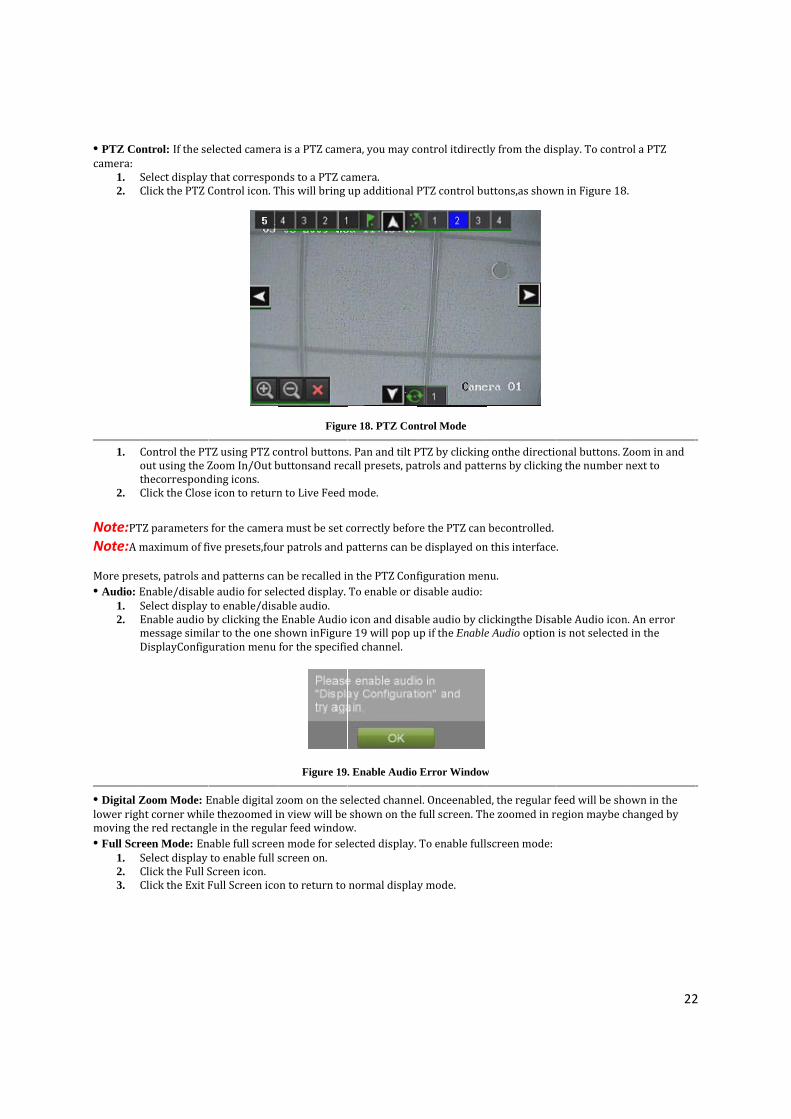
• PTZ Cocamera:
1. 2.
1.
2. Note:PTNote:A More pre• Audio:
1. 2.
• Digital Zlower righmoving th• Full Scr
1. 2. 3.
ontrol: If the se
Select display Click the PTZ C
Control the PTout using the ZthecorrespondClick the Close
TZ parameters maximum of fi
sets, patrols anEnable/disablSelect display Enable audio bmessage similDisplayConfig
Zoom Mode: Eht corner whilhe red rectangreen Mode: EnSelect display Click the Full SClick the Exit F
elected camera
that corresponControl icon. T
TZ using PTZ coZoom In/Out bding icons. e icon to return
for the camerive presets,fou
nd patterns cae audio for selto enable/disaby clicking thear to the one suration menu
Enable digital ze thezoomed ile in the regulanable full screeto enable full sScreen icon. Full Screen ico
a is a PTZ came
nds to a PTZ caThis will bring
Figur
ontrol buttonsbuttonsand rec
n to Live Feed
a must be set cur patrols and p
n be recalled inected display. able audio. Enable Audio shown inFigurefor the specifie
Figure 19.
zoom on the sen view will be ar feed windown mode for selscreen on.
on to return to
era, you may c
amera. up additional P
re 18. PTZ Con
s. Pan and tilt Pcall presets, pa
mode.
correctly beforpatterns can be
n the PTZ ConfTo enable or d
icon and disabe 19 will pop ued channel.
. Enable Audio
elected channeshown on the w. lected display.
normal display
ontrol itdirect
PTZ control bu
ntrol Mode
PTZ by clickingatrols and patte
re the PTZ can e displayed on
figuration mendisable audio:
ble audio by clup if the Enable
Error Window
el. Onceenabledfull screen. Th
To enable full
y mode.
ly from the dis
uttons,as show
g onthe directioerns by clickin
becontrolled.n this interface
nu.
ickingthe Disae Audio option
w
d, the regular fhe zoomed in r
screen mode:
splay. To contr
wn in Figure 18
onal buttons. Zg the number n
.
able Audio iconis not selected
feed will be shoegion maybe c
22
rol a PTZ
8.
Zoom in and next to
n. An error d in the
own in the changed by
2

23
3.2 Using the Display Menu The Display Menu can be accessed by right‐clicking the mouse on any of the display in Live Feed mode. The Display menu, shown in Figure 20 allows you to quickly change into different display modes and to start/stop auto‐switching of the display modes.
Figure 20. Live Feed Display Menu
2x2 Mode: Click to switch to fourchannel display mode.
3x3 Mode: Click to switch to ninechannel display mode.
4x4 Mode: Click to switch to sixteenchannel display mode.
Main Menu: Click to go to DVR MainMenu. If Lock Main Menu is selected inthe Lock Menus menu, you must enterthe current Admin Password to exit outof the Live Feed.

24
Start/Stop Auto-Switch: Click to start/stop auto‐switch. Auto‐switch will cyclethrough selected cameras. Switching ofcamera can be on an individual ormultiple camera basis. Next Set of Display: Click to view thenext set of display. In 2x2 mode, this willshow the next four display. In 3x3 mode,this will show the next nine display.
Note:In order to use auto‐switching of channels, the dwell time must be configured inthe Display Configuration menu. Note:After 20 seconds of inactivity, the DVR will automatically exit out of the Displaymenu and go back into the Live Feed mode. Note:The Lock Main Menu setting is selected by default, meaning the Admin passwordmust be enter to exit out of the Live Feed into the Main Menu. To change this option andremove the lock to the Main Menu, visit the Lock Menus menu (See Locking andUnlocking System Menus on page 59).
3.3 Configuring Live Feed Displays Live Feed displays can be customized to your own needs. These settings can be accessedby entering the Display Configuration menu, shown in Figure 21.
Figure 21. Display Configuration Menu
To customize display settings: 1. Enter the Display Configuration menu by going to Main Menu > System Configuration> Display
Configuration. 2. Select the Video Output to configure. You may configure either the VGA, MainCVBS or Spot CVBS. 3. The settings available to configure for each video output includes:

25
• Screen Configuration: Screen configuration of each video output. Youmay select between a 1x1, 2x2 or 4x4 configuration.
• Sequencing Dwell Time: The time in seconds to dwell between switchingof channels when Start Sequence is selected in Live Feed. Selecting DisableSwitching will disable switching in Live Feed.
• Enable Audio: Enables/disables audio output for the selected video output. • Output Format: Designates the video output standard. • Device Name/No.: Designates the device name and number of the currentunit. • VGA Resolution: Designates the resolution of main VGA display. • Mouse Pointer Speed: Pointer speed of the mouse, the higher theamount, the faster the mouse
would move.
3.4 Setting Camera Order Setting the camera order allows you to logically position cameras for more efficientmonitoring of your own individual location.
Figure 22. Camera Order Setting
To set the camera order:
1. Enter the Display Configuration menu, shown in Figure 20 by going to MainMenu > System Configuration > Display Configuration.
2. Select the Video Output to configure camera order for. 3. Select the Screen Configuration you would like to use in Live Feed. The previewof the screen configuration on the
right will change depending on theoption selected. 4. Each display in the preview of the screen configuration will have a selectionbox containing a list of the different
cameras that are available on the DVR. 1. Pressing the up and down button of each selection box, select the camera youwould like to show in the particular
display. Selecting ‘X’ will disable the display. 5. Click the Previous and Next button to go to the next set of displays for theselected screen configuration. For example,
in 2x2 screen configuration mode,pressing the Next button will bring up the next set of 4 displays. 6. Click the Save button to Save settings. 7. Repeat steps 2-6 to adjust the camera order for other video outputs. 8. Click the Exit button to exit out of the menu.
Note:You must click the Save button after adjusting the order of one video output beforeyou are able to move on to adjust another one.

26
C H A P T E R 4
Record Settings
4.1 Configuring Settings for Recording There are multiple ways to setup your DVR for recording. They include setting up arecording schedule, triggering a recording by motion detection and/or a sensor alarm, andmanually starting the recording.
4.1.1 Configuring Recording Settings Before setting your DVR up for recording, certain settings should be configured first.These settings can be found in the Recording Configuration menu, shown in Figure 23.
Figure 23. Recording Configuration Menu
The first set of settings to configure in this menu is the recording quality settings. Toconfigure the recording quality settings:
1. Enter the Recording Quality Settings menu by going to Main Menu > RecordingConfiguration > Recording Quality Settings. The Recording Quality Settingsmenu is shown in Figure 24.
Figure 24. Recording Quality Settings Menu
2. Select the camera to configure in the camera drop down menu on the upperleft of the menu. If all cameras are to be configured with the same settings,select All Cameras from the list.
27
3. Select the Encoding Parameters mode to configure. Either Continuous or OnEvent can be selected. 4. Select the camera resolution in the Resolution drop down menu The optionsfor the camera resolution includes
4CIF,CIF and QCIF. 5. Select the recording Frame Rate to use for the designated camera. A rate of25 all the way down to 1of a frame can be
selected. 6. Set the picture quality using the Picture Quality slider. A preview of theselected picture quality will be shown on the
right preview screen. Increasingthe picture quality will also increase the bit rate of the video feed. The resolutionand frame rate of the feed will be adjusted automatically.
7. Select the Pre-record time. The pre-record time is the time in seconds to alsorecord before a recording is triggered. Setting the pre-record time to MAX willallow the DVR to use up to the maximum available buffer space for recording.
8. Select the Post-record time. The post-record time is the time in seconds toalso record after a recording has ended. 9. Enter the Files Removed After time. The Files Removed After time denotesthe amount of days that files will be
deleted after its initial recording. Settingthe time to 0 will allow the DVR to only delete and overwrite files when theHDD is full.
10. Repeat steps 3-9 for other Encoding Parameters mode. 11. Select the Save button to save the recording quality settings and select Exit toreturn to the previous menu. Selecting the
Exit button without clicking Savewill quit out of the menu without saving settings. Note:For 7204HVI‐ST Series, when resolution is 4CIF,Frame rate can be set as 12 all the way down to 1. For 7208HVI-ST Series, when resolution is 4CIF, Frame rate can be set as 8 all the way down to 1,But for 7216HVI-ST Series, when resolution is 4CIF, Frame rate can only be set as 6 all the way down to 1.
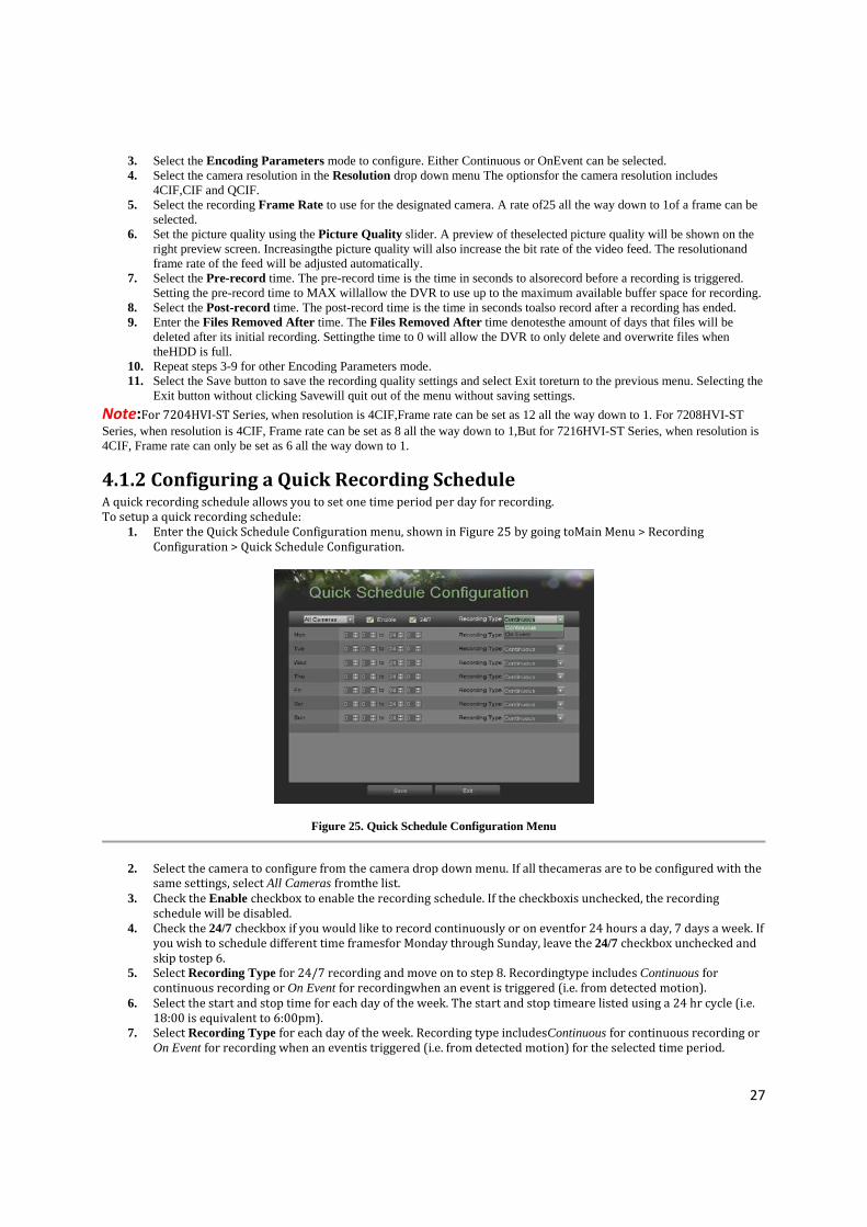
4.1.2 Configuring a Quick Recording Schedule A quick recording schedule allows you to set one time period per day for recording. To setup a quick recording schedule:
1. Enter the Quick Schedule Configuration menu, shown in Figure 25 by going toMain Menu > Recording Configuration > Quick Schedule Configuration.
Figure 25. Quick Schedule Configuration Menu
2. Select the camera to configure from the camera drop down menu. If all thecameras are to be configured with the
same settings, select All Cameras fromthe list. 3. Check the Enable checkbox to enable the recording schedule. If the checkboxis unchecked, the recording
schedule will be disabled. 4. Check the 24/7 checkbox if you would like to record continuously or on eventfor 24 hours a day, 7 days a week. If
you wish to schedule different time framesfor Monday through Sunday, leave the 24/7 checkbox unchecked and skip tostep 6.
5. Select Recording Type for 24/7 recording and move on to step 8. Recordingtype includes Continuous for continuous recording or On Event for recordingwhen an event is triggered (i.e. from detected motion).
6. Select the start and stop time for each day of the week. The start and stop timeare listed using a 24 hr cycle (i.e. 18:00 is equivalent to 6:00pm).
7. Select Recording Type for each day of the week. Recording type includesContinuous for continuous recording or On Event for recording when an eventis triggered (i.e. from detected motion) for the selected time period.

28
8. Select the Save button to save the schedule settings and select Exit to return tothe previous menu. Select the Exit button without clicking Save will quitout of the menu without saving settings.
Note:On Event recordings are recordings that are triggered from motion detection and/or from an external alarm (See Configuring Alarms and Exceptions on page 61). Note:If an event occurs during Continuous recording, the frame rate will automaticallyswitch to that set for Event recording.
4.1.3 Configuring an Advanced Recording Schedule An advanced recording schedule allows you to schedule multiple time periods per day forrecording as oppose to a single time period of a quick recording schedule. Setting up anadvanced recording schedule will allow you to further conserve disk space by recordingonly during the time periods you would like to record at. To setup an advanced recording schedule:
1. Enter the Advanced Schedule Configuration menu, shown in Figure 26 bygoing to Main Menu > Recording Configuration > Advanced Schedule Configuration.
Figure 26. Advanced Schedule Configuration Menu
2. Select the camera to configure from the camera drop down menu. If all thecameras are to be configured with the same
settings, select All Cameras fromthe list. 3. Check the Enable checkbox to enable the recording schedule. If the checkboxis unchecked, the recording schedule will
be disabled. 4. Select a day between Monday to Sunday to configure schedule for. 5. Setup time periods for schedule. If the 24HR checkbox is checked, recordingwill occur over the entire day. To setup
multiple time periods, uncheck 24HRand enter the Start and Stop Time for the selected day. The start and stop timeare listed using a 24 hr cycle (i.e. 18:00 is equivalent to 6:00pm).
6. Select recording type under Type for selected day of the week. Recording typeincludes Continuous for continuous recording or On Event for recording whenan event is triggered (i.e. from detected motion) for the selected time period.
7. If there are scheduling errors detected, such as overlapping time periods, errormessages such as those shown in Figure 25 will appear.

29
Figure 27. Advanced Schedule Configuration Error Messages
8. Select the Add button to add time frame to schedule. The newly added timeframe will appear in the schedule on
the left, with the schedule parametersshown on the right. Continuous recordings are shown in blue on the schedulewhile event recordings are shown in yellow. An example of this can be seenin Figure 28.
Figure 28. Advanced Schedule Configuration Example
9. Repeat steps 4‐10 to setup additional time periods for the selected day. 10. Select the Save button to save the schedule settings and select Exit to return tothe previous menu. Selecting the
Exit button without clicking Save will quitout of the menu without saving settings. Note:Creating a schedule in the Quick Schedule Configuration menu will also create aschedule in Advanced Schedule Configuration. The quick schedule will show up as a timeperiod in the Advanced Schedule Configuration.

30
C H A P T E R 5
Playback
5.1 Playing Back a Recording Previously recorded files can be played back using the Playback Interface. You must firstsearch for recordings to play them back.
5.1.1 Understanding the Playback Interface It’s important to understand how to use the Playback Interface to efficiently navigatethrough recorded files. To access the Playback Interface, shown in Figure 29, go to MainMenu > Playback.
Figure 29. Playback Interface Menu
Some of the main features of the Playback Interface includes: • Channel Selector: Select the channel to search for recordings on. • Calendar: Select the date to search for recordings on. • Timeline: Select the time to search for recordings on. • Preview: Shows a preview of the selected recording. • Playback Controls: Controls for playback of the selected recording. • Clip Backup Tools: Tools to backup clips from a recording. • Clip Playback Controls: Controls for playback of marked clip.

31
5.2 Searching for Recorded Files The Playback Interface allows for easy searching of recorded files. To search for recordedfiles using the Playback Interface:
1. Enter the Playback menu, shown in Figure 28 by going to Main Menu > Playback. 2. Select the channel to search for recordings on. 3. Select the date to search for recordings on using the calendar. The system dateis shown at the top of the
calendar. You may change the month and year of thecalendar by clicking the left and right arrows next to the month and year.Dates with continuous recordings in the selected month and channel are displayed inlight blue, and dates are displayed in yellow when they are on event recording. Dates without recordings are dark gray. The active selecteddate is displayed in light gray, as shown in Figure 30.
Figure 30. Playback Menu Example
4. Click on the desired date that is highlighted in light blue to search for recordings.If recordings exist, the timeline
will be filled with blue bars to designaterecorded files. The playback marker, indicated by a green vertical line willautomatically jump to the beginning of the earliest recordings for the selecteddate. The marker can be moved to any other location by clicking on thedesired position on the blue bars.
5. Select the Play button in the Playback Controls to start playback of the recording.

32
5.3 Playing Back Recorded Files After finding the recordings you would like to playback (See Searching for RecordedFiles on page 37), you may use the Playback Controls to navigate through the recording. The controls found under Playback Controls include:
Play Button:Button to playback recording.
Decrease Speed Button: Button to decrease play speed.
Increase Speed Button: Button to increase play speed
Enter/Exit Full-Screen Mode: Button to enter into and exit out of full-screen mode.
Enable/Disable Audio:Button to enable and disable audio in playback mode.
Figure 31. Playback control buttons
To playback recorded files:
1. Search and select recording to playback in the Playback Interface. 2. Click the Play button to begin playback of selected recording and the Pausebutton to pause playback. 3. You may slow down or speed up the playback speed by clicking the DecreaseSpeed/Increase Speed button. 4. Click the Full‐Screen button to enter full‐screen playback mode, shown in Figure 32
Figure 32. Full-Screen Playback Mode
5. In full‐screen mode, you may hide the toolbars by clicking the Hide Toolbarbutton. Clicking the Exit Full‐Screen
button will return you to the originalplayback mode. 6. Click the Enable/Disable Audio button to turn on and off audio during playback. 7. Click the Digital Zoom button to enable digital zoom. Once enabled, the regularrecorded feed will be shown in
the lower right corner while the zoomed inview will be shown on the full screen. The zoomed in region may be changedby moving the red rectangle in the regular recorded feed window.
8. Click the Exit button to return to the previous menu.

33
5.4 Playing Back Multiple Channels You may also playback recordings from multiple channels simultaneously. To playbackrecordings from multiple channels: 1. Search and select recording to playback in the Playback Interface. 2. Enter into Full‐Screen mode, shown in Figure 30 by clicking the Full‐Screenbutton. 3. In Full‐Screen mode, you may select additional channels to playback by clickingthe checkbox next to the desired camera in the Channel Selector panel. Playbackwill begin simultaneously on the selected channels. 4. You may stop playback on any of the channels by un‐checking the checkboxnext to the channel. Note:Up to4 channels can be played back at the same time.
C H A P T E R 6
Backup
6.1 Backing Up Video Clips Video clips can be backed up to various devices, such as USB flash drives, USB HDDs or aDVD writer.
6.1.1 Selecting Video Clips Video clips can be selected for backup in the Playback Interface using the controls found inthe Mark Clip For Backup panel, shown in Figure 33.
Figure 33. Mark Clip For Backup Controls
The controls found in the Mark Clip For Backup panel includes:
• Start Clip Button: Mark the starting point for the video clip. • Stop Clip Button: Mark the ending point for the video clip. • Play Clip Button: Play the selected video clip. • Save Clip Button: Save the selected video clip to the HDD. • Clear Clip Button: Clear the selected video clip.

34
To select video clips in the Playback Interface: 1. Enter the Playback Interface, shown in Figure 34 by going to Main Menu >Playback.
Figure 34. Playback Menu
2. Search for the recorded files that you would like to select video clips from(See Searching for Recorded Files on page 35). Video clips can only beselected in single playback mode.
3. Select the starting position of the video clip by clicking the desired location onthe blue recordings bar. 4. Click the Start Clip button. 5. Select the ending position of the video clip. 6. Click the stop Clip button. 7. The selected video clip time range will be shown at the bottom of the PlaybackInterface, as seen in Figure 35.
Figure 35. Video Clip Time Range
8. You may play the video clip using the Play Clip button or use the arrow keysshown next to the clip time range to progress through the video one second,minute or hour at a time.
9. Click the Save Clip button to save clip to the DVR. Clip must be first saved tothe DVR before it can be backed up to an external USB storage device or to aDVD writer. Clicking the Clear Clip button will remove the video clip.
10. Repeat steps 2‐7 to select additional clips. If you would like to backup videoclips at this point, click the Backup button.
Note:The Play Clip, Save Clip and Clear Clip buttons are not available unless a completedvideo clip is selected. A completed video clip has a start and end point marked by using theStart Clip and End Clip button. Note:The Start Clip button is not available when there is still a video clip that has notbeen saved or cleared.
6.2 Backing Up Video Clips After video clips have been selected in the Playback Interface (See Selecting Video Clipson page 46), you may back them up to an external USB storage device or DVD writer bygoing to the Backup menu. To backup video clips:
1. Enter the Clips Backup menu, shown in Figure 36 by first going to Main Menu> Playback. In the Playback menu, click the Clips Backup button.

35
Figure 36. Clips Backup Menu
2. If video clips were successfully saved to the HDD using the Playback Interface,they will be listed under the
Backup Clips heading on the left hand side of themenu. The camera number as well as the time range would be listed.
3. Select the video clips you would like to backup by checking the checkbox nextto the desired clips. You may also click the Play icon to play and review theclip. Video clips can be deleted by selecting it and clicking the Remove buttonor by clicking the Remove All button to delete all clips.
4. Connect at least one USB storage device to the DVR. If the device is compatiblewith the DVR, it will automatically be detected. Select the backup device fromthe Backup Device drop down menu.
5. The Clips Selected, Required Space and Available Space will be displayed onthe Clips Backup menu. If the USB storage device has not been properly initializedand formatted, you may click on the Format button to do so. It isimportant to note that formatting will delete ALL data from the storage device.
6. If the available space on the storage device is adequate, select the Backup buttonto begin backup of the selected clips.
7. After clips have been backed up, you may click the Playback button to return tothe Playback Interface or the Done button to return to the previous menu.
Note:Formatting a storage device will permanently delete all the files on that device. There is also NO WARNING MESSAGE after clicking the Format button to format thestorage device. Please proceed with caution and backup all critical data from the storagedevice before formatting.
6.3 Backing Up Recorded Files Not only can video clips be backed up, full recorded files can also be backed up to a storagemedium. To back up recorded files:
1. Search for recorded files using the File Management menu (See Searchingfor Recorded Files on page 83). 2. Select the files you would like to backup by checking the box next to the file.You may also check the All File box
to backup all files. The total required spacewill be shown next to Total Size. 3. Click the Files Backup button, this will take you to the Files Backup menu, asshown in Figure 37.

36
Figure 37. Files Backup Menu
4. In the Files Backup menu, connect a USB storage device and click the Refreshbutton. If the device is detected, a list of its file contents as well as the availablefree space will be shown. 5. You may delete files on the USB storage device to free up additional storagespace by clicking the Delete button on the selected file. You may also formatthe device by clicking the Format button. Formatting will remove ALL filesfrom the device. 6. When there is sufficient storage space for backup, click the Backup button. Abackup progress bar will be shown. 7. Click the OK button once backup has completed. 8. Click the Exit button to return to the File Management menu.

37
C H A P T E R 7
System Configuration
7.1 Configuring Network Settings
7.1.1 Network configuration Network settings must be configured before you’re able to use your DVR over the network. To configure network settings:
1. Enter the Network Configuration menu, shown in Figure 38 by going to MainMenu > System Configuration > Network Configuration.
Figure 38. Network Settings Menu
2. The current network settings are displayed on the right side of the menu. 3. If you have a DHCP server running and would like your DVR to automaticallyobtain an IP address and other
network settings from that server, check theDHCP checkbox. 4. If you would like to configure your own settings, enter the settings for:
• IP Address: IP address you would like to use for your DVR. • Subnet Mask: Subnet Mask of network. • Default Gateway: IP address of your Gateway. Typically the IP address ofyour router. • DNS Server: The preferred and alternate Domain Name System (DNS)Server to be used with your DVR.
5. To enable Dynamic DNS (DDNS), check the DDNS checkbox. Dynamic DNSallows you to create a hostname and associate it to your IP address, makingaccess to your DVR over the internet easier. To configure DDNS: 1. Enable DDNS by checking the DDNS checkbox. 2. Select a DDNS provider from the DDNS Provider selection box. 3. Enter settings for Server Address, DVR Domain Name, User Name, andPassword.
6. If a central monitoring station that is compatible with your DVR is available,you may enter its settings under Central Station IP and Central Station Port.
7. Enter the Client Port and HTTP Port to be use with your DVR. The clientport designates the port to be use with the client software while the HTTPport refers to the one to be use with the built‐in Web Server.
8. After all settings have been configured; you may test the connection by clickingthe Test Connection button. A confirmation message, similar to the oneshown in Figure 39 will pop up if the network is working properly.

38
Figure 39. Test Connection Confirmation
9. Select the Save button to save the network settings and select Exit to return tothe previous menu. Selecting the
Exit button without clicking Save will quitout of the menu without saving settings.
7.1.2 Extended remote connection Extended remote connection is used for adding more network visitors with sub stream. Check “Extended remote connection” to enable this function. 7204HVI‐ST support up to 24 network visitors, six for each channel. 7208HVI‐ST support up to 48 network visitors. 7216HVI‐ST support up to 50 networks visitors. If you don’t enable this function, then 7208HVI‐ST/7216HVI‐ST only support up to 24 network visitors. You have no need of checking “Extended remote connection” when it is 7204HVI‐ST. .
7.2 Managing User Accounts By default, DVR comes with two user accounts, the Administrator account and the Guest accounts. TheAdministrator user name is admin and the password is 12345. The default password forAdministrator should be changed right away for security reasons. The Administrator hasthe authority to add, delete or configure parameters for many of the system functions. The Guest accounts user name is guest without password. You can easily switch between accounts by click Login/Logout at the lower left corner of the main menu.
7.2.1 Adding a New Remote/Local User You may add up to 30 new users to your DVR. To add new users:
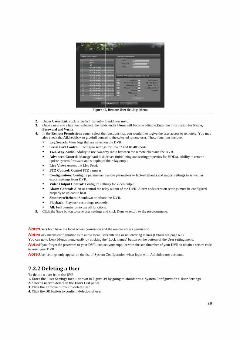
1. Enter the User Settings menu, shown in Figure 40 by going to MainMenu > System Configuration > User Settings.
2. 3.
4.
5.
Note:UsNote:LoYou can gNote:If to reset yoNote:Us
7.2.2 DTo delete1. Enter t2. Select a3. Click th4. Click th
Under Users LOnce a new enPassword and In the Remote also check the • Log Searc• Serial Por• Two-Way• Advanced
update sys• Live View• PTZ Con• Configur
export set• Video Ou• Alarm Co
properly t• Shutdown• Playback• All: Full pClick the Save
sers both have tock menus confgo to Lock Menyou forget the p
our DVR. ser settings only
Deleting a user from thhe User Settina user to deletehe Remove buthe OK button to
List, click on Setry has been selVerify. Permissions pAllcheckbox toch: View logs trt Control: Coy Audio: Abilitd Control: Manstem firmware w: Access the Lntrol: Control Pation: Configutings from DVR
utput Control: ontrol: Alert oro upload to hosn/Reboot: Shut
k: Playback recopermission to ubutton to save
the local accessfiguration is to anus menu easilypassword to yo
y appear on the
a User he DVR: ngs menu, showe in the Users Ltton to delete uo confirm dele
Figure 40
elect this entry tlected, the field
panel, select the o givefull controthat are saved o
onfigure settingsty to use two-wnage hard disk and stoppingof
Live Feed. PTZ cameras. ure parameters, rR. Configure setti
r control the relst. tdown or rebooordings remotel
use all functionsuser settings an
s permission andallow local user
y by clicking theur DVR, contac
list of System
wn in Figure 39List panel. user. etion of user.
0. Remote User
to add new userds under Users w
functions that yol to the selecteon the DVR. s for RS232 and
way radio betwedrives (initializ
f the relay outpu
restore paramet
ings for video olay output of the
ot the DVR. ly. s. nd click Done to
d the remote acrs entering or ne’ Lock menus’ct your supplier
Configuration w
9 by going to M
Settings Menu
r. will become ed
you would likeed remote user.
d RS485 ports.en the remote c
zing and settingut.
ters to factoryd
output. e DVR. Alarm
o return to the p
ccess permissionnot entering men’ button on the br with the serial
when login with
MainMenu > Sy
ditable.Enter the
togive the userThese function
clientand the DVproperties for H
efaults and imp
andexception s
previousmenu.
n. nus.(Details seebottom of the Ulnumber of you
h Administrato
ystem Configur
e information fo
r access to remons include:
VR. HDDs). Ability
port settings to a
settings must be
e page 60 ) User setting menur DVR to obtai
r accounts.
ration > User S
39
or Name,
otely. You may
to remote
as well as
e configured
nu. in a secure code
Settings.
9
y
e

5. Click th
7.2.3 ETo edit a 1. Enter t2. Select a3. Edit usNew Rem4. Click Sa Note:Paenter in th
Note:Usenter char
7.2.4 S
On the m
7.3 C
he Done button
Editing auser: he User Settinga user to edit iner informationote User on paave button to s
assword of Admhe older passwo
ser password caracters.
Switch U
main menu (see
Config
n to exit menu.
a User
gs menu, shown the Users Lisn in the Users aage 54. save settings a
ministrator can bord will appear a
an be both numb
ser
e in Figure 41
,click
guring
.
wn in Figure 39st panel. and Remote Pe
nd Done butto
be modified in Uafter clicking sa
bers and charac
F
), information
k Login/Logou
PTZ C
9 by going to M
ermissions pan
on to exit menu
User setting meave button, ente
cters. You can c
Figure 41.Main
n about users a
ut to switch us
amera
MainMenu > Sy
nel. Remoteper
u.
enu. If passworder in the right p
click the button
Menu
are show on th
sers.
as
stem Configur
rmissions are d
d of administraassword and cli
n on the p
he lower left c
ation > User Se
defined above
ator is changed, ick Done button
password editab
corner,
40
ettings
in Adding a
a dialog box ton to exit.
ble fields to
0
o

41
7.3.1 Configuring Basic PTZ Settings Settings for a PTZ camera must be configured before it can be used. Before proceeding,verify that the PTZ and RS-485 of the DVR are connected properly. To configure PTZ settings:
1. Enter the PTZ Configuration menu, shown in Figure 42 by going to MainMenu > System Configuration > PTZ Configuration.
Figure 42. PTZ Configuration Menu
2. Select the Serial Settings tab. 3. Select the camera to configure in the camera drop down menu on the upperleft of the menu. If all cameras are to be
configured with the same settings,select All Cameras from the list. 4. Configure PTZ settings, including those of Baud Rate, Data Bit, Stop Bit, Parity,Flow Ctrl, Protocol and Address
according to the parameters of the PTZcamera(s). 5. Click the Save button to save current settings.
To test and verify PTZ settings:
1. Enter the PTZ Configuration menu, shown in Figure 41 by going to MainMenu > System Configuration > PTZ Configuration.
2. Select the On Camera Settings tab. This will open up the On Camera Settingsmenu, shown in Figure 43.
Figure 43. PTZ Configuration

42
3. Select the camera to test in the camera drop down menu. 4. Using the Directional buttons and other PTZ control buttons (Zoom In/Out,Focus In/Out, Iris In/Out), test the
functionality of the PTZ camera. If PTZcamera and protocol supports it, you may also click the Auto-Scan button totest its function. PTZ controls buttons are shown in Figure 44.
Figure 44. PTZ Controls Button
5. If PTZ camera is not working properly, make sure PTZ is connected and configuredwith the correct settings under the Serial Settings tab.
6. Click Done to exit and return to the previous menu.
7.4 Customizing PTZ Presets, Patterns and Patrols Your DVR allows you to customize presets, patterns and patrols for a connected PTZ ,camera. A PTZ camera must first be configured before PTZ presets, patterns and patrolscan be customized (See Configuring Basic PTZ Settings on page 57). To customize PTZ presets:
1. Enter the PTZ Configuration menu, shown in Figure 42 by going to MainMenu > System Configuration > PTZ Configuration.
2. Select the On Camera Settings tab. 3. Select Save Presets and move the camera to the desired position using thePTZ control buttons. 4. Double-click on a preset number in the upper left corner of the screen. Thecurrent position of the PTZ camera will be
set for the selected preset number. 5. To test the newly configured preset, first move the PTZ camera to a differentposition. Select Recall Presets and click
on the preset number. The camerashould move to the location that was set for the selected preset number. 6. Click the Done button to exit out of the PTZ Configuration menu.
Note:Only the first 23 presets are shown in the table. To save or recall more presets,click on the “...” button. Clicking the “...” button will bring up a selection list for presets up to200. To customize PTZ patterns:
1. Enter the PTZ Configuration menu, shown in Figure 42 by going to MainMenu > System Configuration > PTZ Configuration.
2. Select the On Camera Settings tab. 3. Select a Pattern Number to set from the drop down list. 4. Click the Record button to begin recording the movement of the PTZ. 5. Move the PTZ to the desired locations using the PTZ control buttons. 6. Click the Save button to save pattern. 7. To test out your new pattern, click the Play button. The PTZ should move as itdid during the recording process. You
may click the Stop button at any time toend the pattern. Clicking the Play button again will start playing the PTZ patternagain at the initial position.
8. Click the Done button to exit out of the PTZ Configuration menu. To customize PTZ patrols:

1.
2. 3. 4.
5. 6. 7. 8. 9.
7.5 C
7.5.1 SSet up prorelevant ev To set up 1. Enter thDetection
2. Select twith the sa3. Check tdisable mo4. Set the the higher5. Set the area. A reon areas thScreen busection fro6. If you’r7. Select tavailable i
Enter the PTZ Configuration. Select the On CSelect a PatrolSelect a Presetpatrol. Click the Add bRepeat steps 4-Click the Up anTo test out youClick the Done
Configu
Setting Upoperly, using movents rather tha
motion detectiohe Motion DeteSettings.
the camera to coame settings,sethe Enable Mootion detection.motion detectio
r the sensitivity motion detectiod grid will beshhat overlap the
utton to include om the motion dre not satisfied wthe Actions to tincludes:
Configuration m
Camera Settinl Number to set Number that i
button. The Pre-5 until you havnd Down button
ur new preset, ce button to exit
uring A
p Motion otion detected ran everything, w
on: ection Settings m
onfigure in the lect All Camera
otion Detection. on sensitivity bywillbe to motio
on region in thehown, designaticurrent selectedthe whole area detection regionwith the selectetake if motion is
menu, shown in
ngs tab. et from the dropis next to the P
eset Number wve included all tn at the bottom lick the Play buout of the PTZ
Alarms
Detectionrecording will iwhich willalso m
menu, shown in
Figure 45. M
camera drop doas from the list.
n checkbox to en
y adjusting the on. e preview screening that the seledmotion detectiinto the motion
n. ed region, you ms detected in th
n Figure 42 by g
p down list. atrol Number
will be added tothe presets you of the list to ch
utton. The PTZ Configuration
s and E
n increase the nummake searching
n Figure 45 by g
Motion Detectio
own menu on th. nable motion de
green Sensitivi
n on the right sected area is parion area will inn detection regi
may click the Ce designated re
going to MainM
from the dropd
the patrol list.would like to h
hange the order should movethmenu.
Excepti
mber of days yog for events easi
going toMain M
on Settings Men
he upperleft of t
etection forthe
ity bar. Themor
ide of themenurt of the motionclude them intoion.Left-clickin
Clear buttonto regions. Moretha
Menu > System
down list that yo
haveon the patroofthe presets in
hrough the list o
ions
ourDVR is ableier.
Menu > Recordi
nu
the menu. If all
selected camera
re lime green re
u by left-clickingn detectionregioo the region. Yong on any part o
eset the motion an one action ca
Configuration
ou would like to
ol. n the patrol. of added presets
e to record. It w
ing Configurati
l cameras are to
a. Uncheck the
ectangles select
g with the mouon. Dragging orou may also clicof the grid will r
detection area.an be selected. T
43
> PTZ
o add to the
s.
will only record
on > Motion
o be configured
checkbox to
ted in the bar,
se on an open r left-clicking ck theFull remove that
The actions
3

8. Select tExit butto
7.5.2 CRecording
1.
2. 3.
4.
5. 6.
Certain ac
1.
2.
• Sound Aucamera.
• Pop-up Im• Notify Su• Send Ema• Trigger A
the Alarmthe Save buttonon without clic
Configurgs can also be Enter the TrigSettings.
Select the RecSelect the cambe configured Check the Enacheckbox to diSelect the triggSelect the SaveExit button wi
ctions can alsoEnter the TrigSettings. Select the Trig
udio Warning:
mage on Moniturveillance Cenail: DVR will s
Alarm Output:m Output list, whn to save the mcking Savewill
ring Alarmtriggered fromgger Settings m
ording Triggemera to configuwith the same
able Trigger Evisable trigger eger inputs thate button to savithout clicking
o be performedgger Settings m
gger Actions ta
: DVR will soun
tor: DVR will nter: DVR willsend an email o: DVR will trigghere theoutput tmotion detectioquit out of the
m Inputsm an external smenu, shown in
Figure
rs tab. ure in the camee settings,selecvents checkboxevents. t you would likve the trigger sSave will quito
d if an alarm inmenu, shown in
ab, this will tak
nd an audio wa
show an imagel notify surveillaout to the designger alarm outputo trigger can bon settings and menu without
s ensor alarm den Figure 46 by g
e 46. Trigger Se
era drop down ct All Cameras x to enable trig
ke to associate settings and seout of the men
nput is triggeren Figure 45 by g
ke you to the T
arning if motion
e of what causedance center whenated recipientsut when motione selected. d select Exit tot saving setting
evice. To setupgoing to Main
ettings Menu
menu on the ufrom the list.gger events for
with the selecelect Exit to retnu without savi
ed. To setup trigoing to Main
Trigger Actions
n isdetected in th
d themotion on enmotion is det
s whenmotion isn isdetected. Sel
return to the pgs.
p recordingtrigMenu >Record
upperleft of the
r theselected c
cted camera. turn tothe preving settings.
iggeractions: Menu >Record
s submenu,sho
he designated r
the monitor. tected. s detected. lecting this opti
previous menu
ggers from alarding Configura
e menu. If all c
camera. Unchec
vious menu. Se
ding Configura
wn in Figure 4
44
regions of the
ion will enable
u. Selecting the
rm inputs: tion > Trigger
cameras are to
ck the
electing the
tion > Trigger
47.
4

45
Figure 47. Trigger Actions Sub-Menu.
3. Select the alarm input to configure in the Alarm Input No. drop down menuon the upper left of the menu. If all alarm inputs are to be configured with thesame settings, select Allfrom the list.
4. Select the Trigger Action for the external alarm input device. Normal Open orNormal Close can be selected. 5. Select the PTZ Actions (only if a PTZ camera is configured on the DVR) to runwhen the alarm input is triggered.
Only one PTZ action can be selected peralarm input. 6. Select the Actions to run when the alarm input is triggered. Multiple actionscan be selected per alarm input. The
actions available includes: • Sound Audio Warning: DVR will sound an audio warning if alarm is triggered. • Pop-up Image on Monitor: DVR will show the corresponding channelthat is associated with the trigger input. • Notify Surveillance Center: DVR will notify surveillance center whenalarm is triggered. • Send Email: DVR will send an email out to the designated recipients whenalarm is triggered. • Trigger Alarm Output: DVR will trigger alarm output when input is triggered.Selecting this option will enable the Alarm Output list, where theoutput to trigger can be selected.
7. Select the Save button to save the trigger settings and select Exit to return tothe previous menu. Selecting the Exit button without clicking Save will quitout of the menu without saving settings.
7.5.3 Configuring Exceptions Actions can also be triggered when the DVR detects certain exceptions. To setup exceptionconfiguration:
1. Enter the Exception Configuration menu, shown in Figure 48 by going toMain Menu > System Configuration > Exception Configuration.
Figure 48. Exception Configuration Menu

46
2. Select the Exception Type to configure. The exception type includes:
• HDD Full: If selected, trigger action when HDD is full. • HDD Error: If selected, trigger action when errors on the HDD aredetected. • Network Failure: If selected, trigger action when a network failure isdetected. • IP Conflict: If selected, trigger action if an IP conflict is detected. • Illegal Login: If selected, trigger action when illegal logins are detected. • Video Exception: If selected, trigger action when an exception such as distortedvideo is detected. • Video Output Standard Mismatch: If selected, trigger action when videooutput standard does not match.
3. Select the Actions to take when the exception is detected. More than oneaction can be selected. The actions available includes: • Sound Audio Warning: DVR will sound an audio warning if exception isdetected. • Notify Surveillance Center: DVR will notify surveillance center if exceptionis detected. • Send Email: DVR will send an email out to the designated recipients ifexception is detected. • Trigger Alarm Output: DVR will trigger alarm output if exception isdetected. Selecting this option will
enable the Alarm Output list, where theoutput to trigger can be selected. 4. Select the Save button to save the exception settings and select Exit to return tothe previous menu. Selecting the
Exit button without clicking Save will quitout of the menu without saving settings.
7.5.4 Configuring Email Settings If you would like to have the DVR send out e‐mails when certain events are detected orexceptions have been triggered, you must first setup the e‐mail settings. To setup e‐mail settings:
1. Enter the Email Configuration menu, shown in Figure 49 by going to MainMenu > System Configuration > Email Configuration.
Figure 49. Email Configuration Menu
2. Under Server Information, enter all pertinent email information, including:
• Server Authentication: Enable if email server requires authentication.Enabling Server Authenticating will enable the User Name and Passwordfields.
• User Name: User name to use for server authentication. • Password: Password to use for server authentication. • SMTP Server: Address for SMTP server. • SMTP Port: Port for SMTP server. • From Email Address: The Fromaddress to use when an e‐mail is sent outfrom the DVR.

3. 4.
5. 6.
C H A
Cam
8.1 T1.
2.
3. 4.
• Attach JPcheckbox
• SSL: EnaEnter To E-maYou may now List by selectiRemove. Select the SaveExit button wi
P T E R 8
mera
To setuEnter the Priv
Select the camall cameras arClick Enable PUp to four privand pink. Usin
PEG: Enablingx) to the out‐goable Secure Socail Address antest the e‐mailng the recipien
e button to savithout clicking
8
Mana
up privvacy Zones men
mera to setup pre to be configuPrivacy Zones. vacy zones canng the mouse, c
g will attach a soing e‐mail. ckets Layer (SSnd click the Addl settings by clnt and clicking
ve the e‐mail seSave will quit
agem
vacy zonu, shown in F
Figur
rivacy zones inured withthe sa
n be used per cclick and drago
small JPEG seg
SL) for out‐goind button. The eicking the Testg
ettings and selout ofthe men
ent
nes: igure 50 by go
re 50.Privacy Z
n using the camame settings, s
camera and areout rectangular
gment (duratio
ng e‐mail. e‐mail addresst button or rem
lect Exit to retunu without savi
oing to Main Me
Zone Menu
mera drop dowselect All Came
e shown using r boxes definin
n can beset ne
will beadded move ane‐mail
urn to thepreving settings.
enu >Camera S
wnmenu on theeras from the li
fourdifferent cng the desired
ext to the Attac
to the Recipien address off th
vious menu. Sel
Setup > Privac
e upper left of tist.
colors, yellow, zones.
47
ch JPEG
nts List. he Recipients
lecting the
y Zones.
the menu. If
green, blue
7

5.
6.
8.2 CVideo tamTo configu
1.
2.
3. 4. 5.
6.
Note:Vi
8.3 CVideo loss To configu
1.
You may clearto clear all zonSelect the Savethe Exit button
Configmpering detectio
ure video tampEnter the VideoTampering Det
Select the camemenu. If all camClick Enable VAdjust the SenSelect Actions include: • Sound Au• Pop-up Im
channel. • Notify Su• Send Ema• Trigger A
enable theSelect the SaveExit button wit
ideo tampering
Configs detection can
ure video loss dEnter the VideoDetection.
r a privacy zonnes. e button to savn without click
guring on can be used tering detectiono Tampering Dtection
.
era to setup vidmeras are to be Video Tamperisitivity for vide to take if video
udio Warning:mage on Monit
urveillance Cenail: DVR will s
Alarm Output:e Alarm Outpute button to savethout clicking S
area is defaulte
guring be enabled on a
detection: o Loss Detectio
e at any time b
ve the privacy king Savewill q
Videoto recognize if :
Detection menu,
Figure 51. V
deo tampering dconfiguredwithing Detection.eo tampering deo tampering is d
: DVR will sountor: DVR will
nter: DVR willsend an email o: DVR will triggt list, where theoe the privacy zoSavewill quit ou
ed as full screen
Videoany of the chan
on menu, shown
by clicking on t
zones settingsquit out of the m
o Tampan area of a cam
shown in Figur
Video Tamperin
detection in usinh the same setti
etection. detected. More
nd an audio washow the corres
l notify surveillaout to the designger alarm outpuoutput to triggenes settings and
ut of the menu w
n. Area setting i
o Loss Dnnels on your D
n in Figure 52 b
the correspond
and select Eximenu without
pering mera is purpose
re 51 by going
ng Detection Me
ng the camera dings, select All C
than one action
arning if tampersponding chann
ance center whenated recipientsut when tamperer can be selected select Exit torwithout saving
is not supported
DetectDVR to detect th
by going to Mai
dingClear Zone
it toreturn to thsaving setting
Detecelycovered and
toMain Menu >
enu
dropdown menuCameras from
n canbe selected
ring isdetected.nelthat is associ
entampering is s whentamperinring isdetected. ed. return to the presettings.
d.
tion he loss ofvideo.
inMenu > Cam
e button or Cle
he previous mgs.
ction to respond acco
> Camera Setup
u on the upper lthe list.
d per channel. T
iated with the ta
detected. ng is detected.
Selecting this o
evious menu. S
era Setup > Vid
48
ear All button
menu. Selecting
ordingly.
p > Video
eft of the
These actions
ampered
option will
electing the
deo Loss
8

49
Figure 52. Video Loss Detection Menu
2. Select the camera to setup video loss detection in using the camera drop downmenu on the upper left of the menu. If all cameras are to be configured withthe same settings, select All Cameras from the list.
3. Click Enable Video Loss Detection. 4. Select Actions to take if video loss is detected. More than one action can beselected per channel. These actions include:
• Sound Audio Warning: DVR will sound an audio warning if video loss isdetected. • Pop-up Image on Monitor: DVR will show the corresponding channelthat is associated with the video loss
channel. • Notify Surveillance Center: DVR will notify surveillance center whenvideo loss is detected. • Send Email: DVR will send an email out to the designated recipients whenvideo loss is detected. • Trigger Alarm Output: DVR will trigger alarm output when video loss isdetected. Selecting this option will
enable the Alarm Output list, where theoutput to trigger can be selected. 5. Select the Save button to save the privacy zones settings and select Exit toreturn to the previous menu. Selecting the
Exit button without clicking Savewill quit out of the menu without saving settings.
8.4 Configuring OSD Settings On Screen Display (OSD) settings can be configured in the OSD Configuration menu. TheOSD is shown in each display in Live Feed and Playback mode. To configure OSD settings:
1. Enter the OSD Configuration menu, shown in Figure 53 by going to MainMenu > Cameras Setup > OSD Configuration.

2.
3.
4. 5.
Select the camecameras are to Configure OSD• Camera N• Display C• Display D• Display W• Date Form• Time For• OSD DispUsing the mouSelect the SaveExit button wit
era to setup OSbe configured w
D settings, incluName: Name oCamera Name:Date: Enable to Week: Enable tomat: Format ofrmat: Format oplay: Display stse, click and dre button to savethout clicking S
Figure 5
SD configurationwiththe same seuding: f selected came: Enable to dispdisplay date in
o display week f date. f time. tyle for OSD.
rag OSD elemene the privacy zoSavewill quit ou
53. OSD Config
n in using the cettings, select A
era. play camera namn OSD.
in OSD.
nts on preview nes settings and
ut of the menu w
uration Menu
camera drop dowAll Cameras fro
me in OSD.
screen to desired select Exit torwithout saving
wnmenu on theom the list.
edlocation. return to the presettings.
e upper left of th
evious menu. S
50
he menu. If all
electing the
0

51
C H A P T E R 9
Disk Management
9.1 Managing Disks
9.1.1 Checking Disk Status The status of all installed hard disk drives (HDD) can be checked under the DiskManagement menu. To check the status of installed disks:
1. Enter the Disk Management menu, shown in Figure 54 by going to Main Menu> System Configuration > Disk Management.
Figure 54. Disk Management Menu
2. There are four different panels found in the Disk Management menu. Theyinclude:
• Disk Utilization: Displays the maximum space available of all disks combined. • Available Disks: Displays a list of all installed disks(include local and network) and their respectivespace
and status. • Status: Displays the available disk space of all disks combined.
3. Click the Done button to exit out of Disk Management.
9.2 Formatting Disk A newly installed hard disk drive (HDD) must be first formatted before it can be used withyour DVR. Formatting the disk will erase all data on it. To format a new disk:
1. Enter the Disk Management menu, shown in Figure 54 by going to Main Menu> System Configuration > Disk Management.
2. Select a disk to format. A disk that has not been formatted will show ErrorDetected as its status. If the disk is one that is newly installed, the status of thedrive will show up as Non-Active and the Reformat button will change to theAdd button.
3. Click the Reformat/Add button. 4. A confirmation message, similar to the one shown in Figure 55 will appear onthe screen. Click the Yes button to
continue formatting process.

52
Figure 55. Disk Format Confirmation
5. A format progress bar (Figure 55) will be shown on the menu. After the diskhas been formatted, the status of the disk will change to Active.
Figure 55. Disk Format Progress Bar
6. Click the Done button to exit out of Disk Management.
9.2.1 Enabling Disk Overwrite Enabling disk overwrite will allow the DVR to overwrite the installed disks once the disksare full. To enable disk overwrite:
1. Enter the Disk Management menu, shown in Figure 54 by going to Main Menu> System Configuration > Disk Management.
2. Check the Overwrite checkbox. 3. Click the Save button. 4. Click the Done button to exit out of Disk Management.
9.3 Managing Files
9.3.1 Searching for Recorded Files Previously recorded files can be searched by criteria in the File Management menu. To search for all recorded files:
1. Enter the File Management menu, shown in Figure 56 by going to Main Menu> File Management.

2.
3. 4. 5. 6. 7. 8.
9. 10.
Select the camewith the letter Acameras in the Select the StarSelect the EndSelect the VideSelect the File Click the SearcA list of results
You may now Click the Done
eras that you wA. Digital camesearch, check t
rt Time. d Time. eo Type. VideoType. File type
ch button or if ys with your sear
play the selecte button to exit
Figu
would like to inceras arelisted onthe Allbox.
o type includes e includes Lockyou would like rch criteria will
Figur
ted file by clickt out of the File
ure 56. File Sear
clude in the searn the second row
Continuous andked and Unlocketo search for onl be shown at th
re 57. File Sear
king the Play be Management
rch Menu
rch. Analog camw, preceded wi
d On Event recoed files. nly locked fileshe bottom of the
rch Results
button that is nt menu.
merasare listed ith the letter D.
ordings.
, theSearch All emenu (Figure
next tothe file.
on the first rowIf you would li
Locked Files b57).
53
w, preceded ike includeall
button.
3

54
9.4 Locking and Unlocking Recorded Files To lock and unlock recorded files:
1. Search for recorded files using the File Management menu (See Searchingfor Recorded Files on page 83). 2. Select the file you would like to lock/unlock. 3. Click the Lock icon for the selected file. 4. Click the Done button to exit out of the File Management menu.
Note: Locked files will never be overwritten until they are unlocked.

55
C H A P T E R 1 0
DVR Management
10.1 Managing System
10.1.1 Upgrading the System Firmware The system firmware for your DVR can be updated from a USB storage device. To update the system firmware:
1. Enter the Firmware Upgrade menu, shown in Figure 58 by going to MainMenu > Maintenance > Firmware Upgrade.
Figure 58. Firmware Upgrade Menu
2. Connect the USB storage device to a USB port on the DVR. 3. Click the Refresh button. The contents of the USB storage device will be shownon the screen. 4. Select the firmware file. The firmware file is named digicap. 5. Click the Upgrade button to upgrade the DVR. The DVR will automaticallyreboot after the upgrade is completed.
If you do not wish to upgrade at thispoint, click the Cancel button.
10.1.2 Restoring Default Settings To restore factory default settings to your DVR:
1. Enter the Factory Default menu, shown in Figure 59 by going to Main Menu >Maintenance > Factory Default.

56
Figure 59. Factory Default Menu
2. Select the OK button to restore factory defaults or select the Cancel button toreturn to the previous menu.
Note:Network information such as IP address, subnet mask and gateway will not berestored.
10.2 Exporting & Importing Configuration
Configuration information from your DVR can be exported to a USB storage device andimported into another DVR. This will allow you to efficiently setup the same configurationon numerous DVRs. To export DVR configuration:
1. Enter the Export/Import Configuration menu, shown in Figure 60 by going toMain Menu > Maintenance > Export/Import Configuration.
Figure 60. Import/Export Configuration Menu
2. Connect the USB storage device to a USB port on the DVR. 3. Click the Refresh button. The contents of the USB storage device will be shownon the screen. 4. Click the New Folder button to create a new folder or the Delete button to deletea file/folder. 5. Select the location where you would like the configuration to be stored on theUSB storage device. 6. Click Export to export a configuration file to USB storage device. The configurationfile will be named devCfg.bin. 7. Click the Exit button to exit out of the Export/Import Configuration menu.
To import DVR configuration:

57
1. Enter the Export/Import Configuration menu, shown in Figure 65 by going toMain Menu > Maintenance >Export/Import Configuration.
2. Connect the USB storage device to a USB port on the DVR. 3. Click the Refresh button. The contents of the USB storage device will be shownon the screen. 4. Select the configuration file. The configuration file is named devCfg.bin. 5. Click the Import button. 6. Click the Exit button to exit out of the Export/Import Configuration menu.
10.3 Viewing System Logs Many events of your DVR are logged into the system logs.To access the system logs and search for these events:
1. Enter the System Logs menu, shown in Figure 61 by going to Main Menu >Maintenance > System Logs.
Figure 61. System Logs Menu
2. Select the date from the Calendar to search for system logs in. The current systemdate is displayed in the upper left
corner of the menu. 3. Select the log type using the Search Type drop down list. Four log types areavailable: Alarm, Exception,
Operation,Information. 4. Click the Search button. The search results will be displayed in a list on theright side of the menu (Figure 62). If there
are more than 2000 entries, clickthe Prev Page or Next Page button to display more entries.
Figure 62. System Log Search Results

58
5. Select an entry to view more detail information about the entry. 6. If applicable, you may also view the associated video to the selected log entryby clicking the Play button. 7. Log files can also be exported onto a USB storage device. To export a log file,connect a USB storage device to the
DVR, select the log files to export and clickthe Export button. 8. Click the Done button to exit out of menu.
10.4 Locking and Unlocking System Menus System menus on your DVR can be locked to prevent unauthorized local access. To lock and unlock system menus:
1. Enter the Lock Menus menu, shown in Figure 63 by going to Main Menu >Maintenance > Lock Menus.
Figure 63. Lock Menus Menu
Figure 64. Lock Menus Menu
2. If you select Administrator(see Figure 68),there is only Main menu you can choose to lock/unlock. 3. If you select other users(see Figure 69),select the menus you would like to lock/unlock by selecting the Lock
iconbeside the menu’s name in the list on the right. You may also choose to lockand unlock all settings or just recording settings by clicking on the correspondingbuttons (Unlock All Settings, Lock All Settings, Lock All RecordingSettings).
4. Once a system menu is locked, access to that menu will only be granted afterthe correct Admin password is entered. 5. Click the Done button to save settings and to return to the previous menu.
Note:In the Lock/Unlock Menu list, you can’t modify menus if they appear dark grey. Note:Lock Menus menu is available when current user is Administrator.


