
DURESCA® TIRESCA® TRAVESCA®GASLINK®
Your independent bushing and busbar supplier
DTOIA Condenser Bushings, 25 – 230 kVTransformer to Air Epoxy Resin Impregnated PaperIEEE Standards C57.19.01 – 2000 and C57.19.00 - 2004
TRAVESCA®
General description
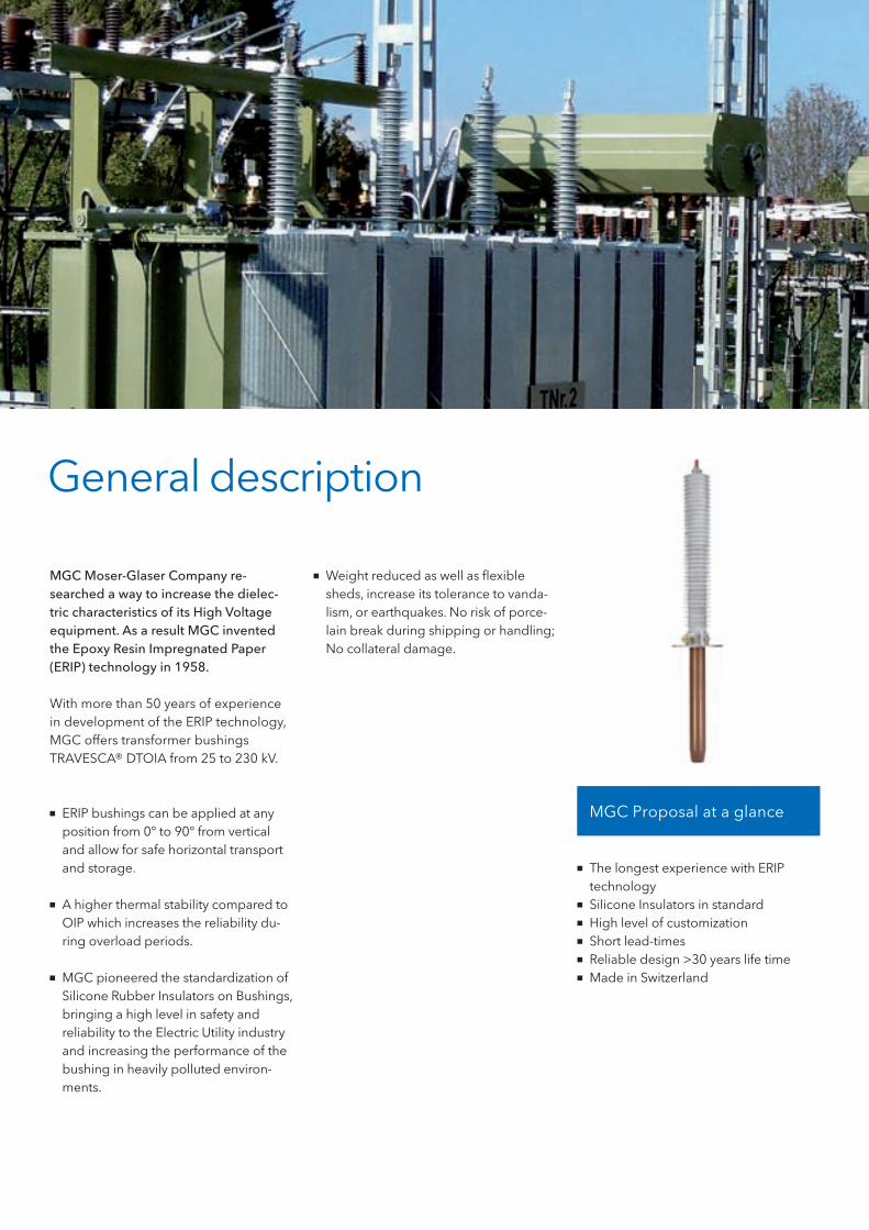
MGC Moser-Glaser Company re-searched a way to increase the dielec-tric characteristics of its High Voltage equipment. As a result MGC invented the Epoxy Resin Impregnated Paper (ERIP) technology in 1958.
With more than 50 years of experience in development of the ERIP technology, MGC offers transformer bushings TRAVESCA® DTOIA from 25 to 230 kV.
■■ ERIP bushings can be applied at any position from 0° to 90° from vertical and allow for safe horizontal transport and storage.
■■ A higher thermal stability compared to OIP which increases the reliability du-ring overload periods.
■■ MGC pioneered the standardization of Silicone Rubber Insulators on Bushings, bringing a high level in safety and reliability to the Electric Utility industry and increasing the performance of the bushing in heavily polluted environ-ments.
■■ Weight reduced as well as flexible sheds, increase its tolerance to vanda-lism, or earthquakes. No risk of porce-lain break during shipping or handling; No collateral damage.
MGC Proposal at a glance
■■ The longest experience with ERIP technology
■■ Silicone Insulators in standard■■ High level of customization■■ Short lead-times■■ Reliable design >30 years life time■■ Made in Switzerland

Replacement bushings
■■ In addition to the standard range, our design, combined with our production process, allows a wide flexibility and adaptability to provide tailor-made solutions.
■■ MGC can interchange bushings from the previous IEEE Std C57.19.01-1991 from 25 to 196 kV. This allows the cus-tomer to replace existing OIP bushings with the modern ERIP technology. The supply chain is simplified as the silicone molding operation is done in-house, MGC can offer short lead-times for its standard range of product.
Features
Silicone housing ERIP active part
■■ DTOIA bushings are delivered in stan-dard with silicon housing which de-monstrates superior’s electrical and mechanical characteristics.
■■ MGC standardized on a minimum 44 mm/kV (heavy) of nominal line-to-ground voltage creepage distance.
■■ The insulation lays directly on the con-ductor or tube and consists of crepe paper dried under vacuum and imp-regnated with epoxy resin. Conductive grading layers are embedded during the winding of the insulation for the best field control. This guarantees the highest operational and human safety.
■■ A strong moisture barrier prevents any contamination or moisture ingress.
■■ MGC design does not use any oil; DTOIA are completely dry and free of partial discharge.
Standard ratings
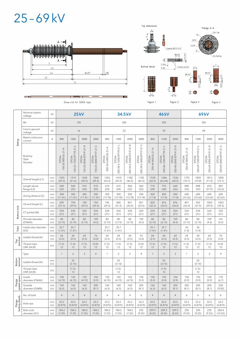
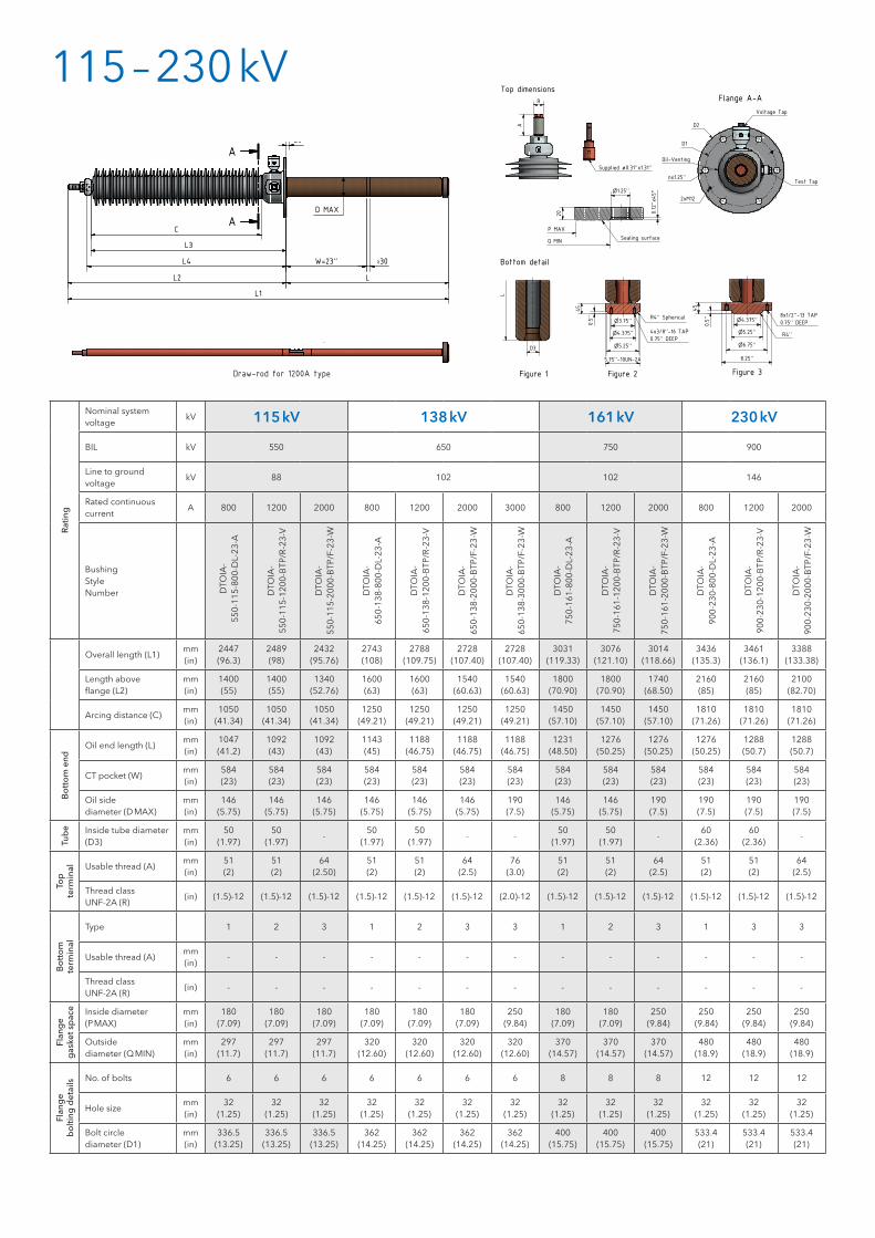
Nominal system voltage kV 25 34.5 46 69 115 138 161 230
Maximum line-to-ground voltage A 16 22 29 44 88 102 102 146
Basic lightning impulse insulation level (BIL) kV 150 200 250 350 550 650 750 900
Rated continuous current A 800 – 3000 800 – 3000 800 – 3000 800 – 3000 800 – 3000 800 – 3000 800 – 3000 800 – 2000
Creepage distance min. 44 mm / kV according to L-G Voltage
Standard routine tests Special tests
All bushings are electrically tested according to IEEE standard C57.19.01-2000. Tightness test with 1.5 Bar overpressure is also performed to any single unit in routine.
MGC performed also tests beyond standard requirements, like mechanical test adapted to bushings dedicated to mobile transformers or special tests to figure out the excellent properties of MGC design under strong climatic conditions.
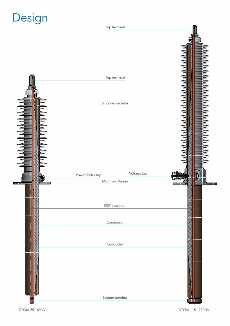
Silicone insulator
Bottom terminal
DTOIA 25 - 69 kV DTOIA 115 - 230 kV
Condenser
Conductor
Mounting flange
Top terminal
Power factor tap Voltage tap
ERIP insulation
Top terminal
Design

Common characteristicsTop terminal
■■ DTOIA top terminal is delivered in Copper Silver Plated as a standard. It's bolted to the head of the bushing. The top terminal is designed for draw-lead, draw-rod and bottom connectors applications.
■■ NEMA top terminal pad can be offered as an optional accessory.
Draw-lead
■■ The maximum continuous current ra-ting of the draw-lead cable is determi-ned by the size and type of the cable supplied by the transformer manufac-turer.
■■ The cable is drawn through the bus-hing and connected to the bolt via brazing.
■■ Maximum cable section is 500mm². The bushings are delivered with cable bolt equipped with a pilot hole Ø 0.31 x 1.31in.
■■ This one has to be drilled according to the lead diameter.
■■ DTOIA design for draw-lead applica-tion does not require additional shiel-ding.
■■ MGC offers various possibilities of draw-lead terminals to ensure a full interchangeability in case of bushing replacement.
Draw-rod
■■ MGC offers extended bushing flexibili-ty and ease-of-use through the use of a draw-rod conductor.
■■ A split copper rod allows easy instal- lation and removal without lowering the oil level, while also providing cur-rent ratings beyond draw-lead ratings.
Bottom connected
■■ Used for bushings with the highest current ratings. A man-hole on the transformer is required to access the connection.
■■ The bushing can be equipped with a removable corona shield as an optio-nal accessory.
Current
■■ The current rating gives the maximum continuous rating with no effect on the bushing life time. Draw-lead; 800A Draw-rod; 1200A Bottom connected; 2000A and above
■■ Bushing rating as well as cable size has to be chosen at least 20% above trans-former rating.
Short-time current level
■■ The bushings withstand a short-time current of 25x rated continuous current for a maximum of 2 seconds.
■■ For draw-lead the short-time current is defined according to the cable cross section in mm²: I = 0.06 x S
Mounting flange
Made of corrosion free aluminium, equipped with
■■ lifting holes■■ Power factor tap (all ratings)■■ Voltage tap (for 115 kV and above)
Power factor, Voltage taps
■■ All bushings have a Power factor tap. The tap is connected to the ground layer.
■■ The grounding is done through the cap. Test voltage is 2 kV, 50Hz for 72sec.
■■ 115 kV and above are additionally equipped with a 20 kV Voltage tap. It’s connected to one of the inner layer from the C1 condenser.
th 2sec (kA)
25 – 69 kVR
atin
g
Nominal system voltage
kV 25 kV 34.5 kV 46 kV 69 kV
BIL kV 150 200 250 350
Line to ground voltage
kV 16 22 29 44
Rated continuous current
A 800 1200 2000 3000 800 1200 2000 3000 800 1200 2000 800 1200 2000 3000
BushingStyleNumber D
TOIA
-15
0-25
-800
-DL-
21-A
DTO
IA-
150-
25-1
200-
BTT
/R-2
1-L
DTO
IA-
150-
25-2
000-
BTF
/F-2
1-R
DTO
IA-
150-
25-3
000-
BTF
/F-2
1-S
DTO
IA-
200-
34.5
-800
-DL-
21-A
DTO
IA-
200-
34.5
-120
0-B
TT/R
-21-
L
DTO
IA-
200-
34.5
-200
0-B
TF/F
-21-
R
DTO
IA-
200-
34.5
-300
0-B
TF/F
-21-
S
DTO
IA-
250-
46-8
00-D
L-21
-A
DTO
IA-
250-
46-1
200-
BTT
/R-2
1-L
DTO
IA-
250-
46-2
000-
BTF
/F-2
1-R
DTO
IA-
350-
69-8
00-D
L-21
-A
DTO
IA-
350-
69-1
200-
BTT
/R-2
1-L
DTO
IA-
350-
69-2
000-
BTF
/F-2
1-R
DTO
IA-
350-
69-3
000-
BTF
/F-2
1-S
Overall length (L1)mm (in)
1255(49.3)
1310(51.6)
1260(49.5)
1260(49.5)
1355(53.3)
1410(55.5)
1182(46.5)
1182(46.5)
1530(60.3)
1586(62.44)
1536(60.5)
1795(70.7)
1850(72.8)
1813(71.4)
1858(73.1)
Length above flange (L2)
mm(in)
560(22)
560(22)
510(20)
510(20)
610(24)
610(24)
560(22)
560(22)
710(28)
710(28)
660(26)
898(35)
898(35)
810(31.9)
855(33.6)
Arcing distance (C)mm(in)
300(11.81)
300(11.81)
300(11.81)
300(11.81)
350(13.78)
350(13.78)
350(13.78)
350(13.78)
450(17.8)
450(17.8)
450(17.8)
600(23.62)
600(23.62)
600(23.62)
600(23.62)
Bo
tto
m e
nd
Oil end length (L)mm(in)
695(27.3)
750(29.5)
750(29.5)
750(29.5)
745(29.3)
800(31.5)
851(33.5)
851(33.5)
820(32.3)
876(34.5)
876(34.5)
897(35.3)
952(37.5)
1003(39.5)
1003(39.5)
CT pocket (W)mm(in)
534(21)
534(21)
534(21)
534(21)
534(21)
534(21)
534(21)
534(21)
534(21)
534(21)
534(21)
534(21)
534(21)
534(21)
534(21)
Oil side diameter (D MAX)
mm(in)
80(3.15)
80(3.15)
80(3.15)
109(4.3)
80(3.15)
80(3.15)
80(3.15)
109(4.3)
80(3.15)
80(3.15)
109(4.3)
80(3.15)
80(3.15)
109(4.3)
141(5.5)
Tub
e Inside tube diameter(D3)
mm(in)
35.7(1.41)
35.7(1.41)
- -35.7
(1.41)35.7
(1.41)- -
35.7(1.41)
35.7(1.41)
-36
(1.4)36
(1.4)- -
Top
term
inal Usable thread (A)
mm(in)
64(2.5)
64(2.5)
64(2.5)
76(3.0)
64(2.5)
64(2.5)
64(2.5)
76(3.0)
64(2.5)
64(2.5)
64(2.5)
64(2.5)
64(2.5)
64(2.5)
76(3.0)
Thread class UNF-2A (R)
(in)(1.5)-
12(1.5)-
12(1.5)-
12(2.0)-
12(1.5)-
12(1.5)-
12(1.5)-
12(2.0)-
12(1.5)-
12(1.5)-
12(1.5)-
12(1.5)-
12(1.5)-
12(1.5)-
12(2.0)-
12
Bo
tto
mte
rmin
al
Type 1 2 3 4 1 2 3 4 1 2 3 1 2 3 4
Usable thread (A)mm(in)
-55
(2.16)- - -
55(2.16)
- - -55
(2.16)- -
55(2.16)
- -
Thread class UNF-2A (R)
(in) -(1.5)-
12- - -
(1.5)-12
- - -(1.5)-
12- -
(1.5)-12
- -
Flan
ge
gas
ket s
pac
e Inside diameter (P MAX)
mm(in)
120(4.72)
120(4.72)
120(4.72)
150(5.9)
120(4.72)
120(4.72)
120(4.72)
150(5.9)
150(5.9)
150(5.9)
150(5.9)
150(5.9)
150(5.9)
150(5.9)
170 (6.7)
Outside diameter (Q MIN)
mm(in)
165(6.5)
165(6.5)
165(6.5)
205(8.1)
160(6.3)
160(6.3)
160(6.3)
205(8.1)
160(6.3)
160(6.3)
205(8.1)
205(8.1)
205(8.1)
205(8.1)
230 (9.05)
Flan
ge
bo
lting
det
ails No. of bolts 4 4 4 4 4 4 4 6 4 4 4 6 6 6 6
Hole sizemm(in)
22.2(0.875)
22.2(0.875)
22.2(0.875)
22.2(0.875)
22.2(0.875)
22.2(0.875)
22.2(0.875)
22.2(0.875)
22.2(0.875)
22.2(0.875)
22.2(0.875)
22.2(0.875)
22.2(0.875)
22.2(0.875)
22.2(0.875)
Bolt circle diameter (D1)
mm(in)
184.2(7.25)
184.2(7.25)
184.2(7.25)
184.2(7.25)
184.2(7.25)
184.2(7.25)
184.2(7.25)
235(9.25)
209.5(8.25)
209.5(8.25)
209.5(8.25)
235(9.25)
235(9.25)
235(9.25)
260.4(10.25)
Flange A-A
1
1
2
2
3
3
4
4
5
5
6
6
A A
B B
C C
D D
A
A
n0.875''
0.12''x45°
Q MIN
P MAX
Sealing surface
R
A
Bottom detail
Top dimensions
Dimensions
15
W=21'' 30≥
L
C
L3
L4
L2
L1
D1
D2
2xM12
nx7/8''
Test Tap
Oil-Venting
3.13''
0.625''
1.75''
0.75''
0.75''
4.13'' 1.75''
0.625''
1.75''
2''
3''
Figure 1 Figure 2 Figure 3 Figure 4
n0.563''
n0.563''
Supplied n0.31''x1.31''
R
A
L
D3
20
3 fixing screws
Draw-rod for 1200A type
115 – 230 kVR
atin
g
Nominal system voltage
kV 115 kV 138 kV 161 kV 230 kV
BIL kV 550 650 750 900
Line to ground voltage
kV 88 102 102 146
Rated continuous current
A 800 1200 2000 800 1200 2000 3000 800 1200 2000 800 1200 2000
BushingStyleNumber D
TOIA
-55
0-11
5-80
0-D
L-23
-A
DTO
IA-
550-
115-
1200
-BTP
/R-2
3-V
DTO
IA-
550-
115-
2000
-BTP
/F-2
3-W
DTO
IA-
650-
138-
800-
DL-
23-A
DTO
IA-
650-
138-
1200
-BTP
/R-2
3-V
DTO
IA-
650-
138-
2000
-BTP
/F-2
3-W
DTO
IA-
650-
138-
3000
-BTP
/F-2
3-W
DTO
IA-
750-
161-
800-
DL-
23-A
DTO
IA-
750-
161-
1200
-BTP
/R-2
3-V
DTO
IA-
750-
161-
2000
-BTP
/F-2
3-W
DTO
IA-
900-
230-
800-
DL-
23-A
DTO
IA-
900-
230-
1200
-BTP
/R-2
3-V
DTO
IA-
900-
230-
2000
-BTP
/F-2
3-W
Overall length (L1)mm (in)
2447(96.3)
2489(98)
2432(95.76)
2743(108)
2788(109.75)
2728(107.40)
2728(107.40)
3031(119.33)
3076(121.10)
3014(118.66)
3436(135.3)
3461(136.1)
3388(133.38)
Length above flange (L2)
mm(in)
1400(55)
1400(55)
1340(52.76)
1600(63)
1600(63)
1540(60.63)
1540(60.63)
1800(70.90)
1800(70.90)
1740(68.50)
2160(85)
2160(85)
2100(82.70)
Arcing distance (C)mm(in)
1050(41.34)
1050(41.34)
1050(41.34)
1250(49.21)
1250(49.21)
1250(49.21)
1250(49.21)
1450(57.10)
1450(57.10)
1450(57.10)
1810(71.26)
1810(71.26)
1810(71.26)
Bo
tto
m e
nd
Oil end length (L)mm(in)
1047(41.2)
1092(43)
1092(43)
1143(45)
1188(46.75)
1188(46.75)
1188(46.75)
1231(48.50)
1276(50.25)
1276(50.25)
1276(50.25)
1288(50.7)
1288(50.7)
CT pocket (W)mm(in)
584(23)
584(23)
584(23)
584(23)
584(23)
584(23)
584(23)
584(23)
584(23)
584(23)
584(23)
584(23)
584(23)
Oil side diameter (D MAX)
mm(in)
146(5.75)
146(5.75)
146(5.75)
146(5.75)
146(5.75)
146(5.75)
190(7.5)
146(5.75)
146(5.75)
190(7.5)
190(7.5)
190(7.5)
190(7.5)
Tub
e Inside tube diameter(D3)
mm(in)
50(1.97)
50(1.97)
-50
(1.97)50
(1.97)- -
50(1.97)
50(1.97)
-60
(2.36)60
(2.36)-
Top
term
inal Usable thread (A)
mm(in)
51(2)
51(2)
64(2.50)
51(2)
51(2)
64(2.5)
76(3.0)
51(2)
51(2)
64(2.5)
51(2)
51(2)
64(2.5)
Thread class UNF-2A (R)
(in) (1.5)-12 (1.5)-12 (1.5)-12 (1.5)-12 (1.5)-12 (1.5)-12 (2.0)-12 (1.5)-12 (1.5)-12 (1.5)-12 (1.5)-12 (1.5)-12 (1.5)-12
Bo
tto
mte
rmin
al
Type 1 2 3 1 2 3 3 1 2 3 1 3 3
Usable thread (A)mm(in)
- - - - - - - - - - - - -
Thread class UNF-2A (R)
(in) - - - - - - - - - - - - -
Flan
ge
gas
ket s
pac
e Inside diameter (P MAX)
mm(in)
180(7.09)
180(7.09)
180(7.09)
180(7.09)
180(7.09)
180 (7.09)
250 (9.84)
180(7.09)
180(7.09)
250(9.84)
250(9.84)
250(9.84)
250(9.84)
Outside diameter (Q MIN)
mm(in)
297(11.7)
297(11.7)
297(11.7)
320(12.60)
320(12.60)
320 (12.60)
320 (12.60)
370(14.57)
370(14.57)
370(14.57)
480(18.9)
480(18.9)
480(18.9)
Flan
ge
bo
lting
det
ails No. of bolts 6 6 6 6 6 6 6 8 8 8 12 12 12
Hole sizemm(in)
32(1.25)
32(1.25)
32(1.25)
32(1.25)
32(1.25)
32(1.25)
32(1.25)
32(1.25)
32(1.25)
32(1.25)
32(1.25)
32(1.25)
32(1.25)
Bolt circle diameter (D1)
mm(in)
336.5(13.25)
336.5(13.25)
336.5(13.25)
362(14.25)
362(14.25)
362(14.25)
362(14.25)
400(15.75)
400(15.75)
400(15.75)
533.4(21)
533.4(21)
533.4(21)
Flange A-A
A
A
Cop
yrig
htby
MG
CM
oser
-Gla
serA
G
Bottom detail
Top dimensions
Dimensions
n1.25''
0.12''x45°
Q MIN
P MAX
Sealing surface
20
R
A
C
L3
L4
L2
L1
D MAX
W=23'' 30≥
L
D2
D1
nx1.25''
2xM12
Voltage Tap
Test Tap
Figure 2 Figure 3Figure 1
Supplied ø0.31''x1.31''
D3
n4.375''
n5.25''
n3.75''
5.75''-10UN-2A
45
0.5''
R4'' Spherical
4x3/8''-16 TAP
0.75'' DEEP
n4.375''
n5.25''
n6.75''
8.25''
45
0.5'' 8x1/2''-13 TAP
0.75'' DEEP
R4''
L
20
3 fixing screws
Oil-Venting
Draw-rod for 1200A type

Busbar system
DURESCA®
Wall bushings
DURESCA®
Busbar system
TIRESCA®
Transformer bushings
TRAVESCA®
SF6 insulated busbar system
GASLINK®
MGC Moser-Glaser Ltd.Lerchenweg 214303 Kaiseraugst / Switzerland
Phone +41 61 467 61 11Fax +41 61 467 61 10E-Mail [email protected] www.mgc.ch
Member of PFIFFNER Group
This document has been drawn up with the utmost care. We cannot,
however, guarantee that it is entirely complete, correct or up-to-date.
© Copyright MGC, Subject to change without notice. 2016.03


