
1
Instructions and Parts List
Dual S867 II "L" ClipApplicatorType 10500
(Section I)
Serial No. For reference, record machine serial number here.
3M-Matic™
3M Industrial Adhesives and Tapes3M Center, Building 220-5E-06St. Paul, MN 55144-1000
3M-Matic™and AccuGlide™ are Trademarks of 3M, St. Paul, MN 55144-1000Printed in U.S.A© 3M 2013 44-0009-2042-9 (C062013-NA)
Important SafetyInformation
Spare Parts
BEFORE INSTALLING OR OPERATING THIS EQUIPMENTRead, understand, and follow all safety and operating instructions.
It is recommended you immediately order the spare parts listed in the "Spare Parts/Service Information" section. These parts are expected to wear through normal use, and should be kept on hand to minimize production delays.

2
Instruction Manual
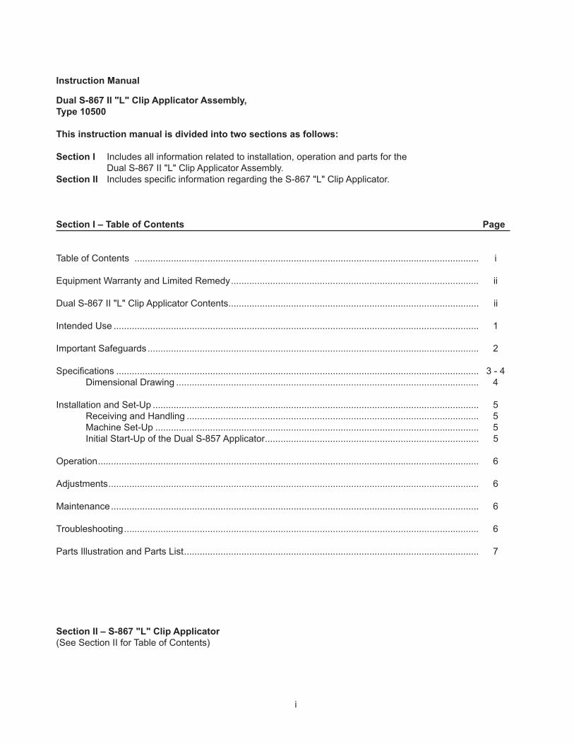
Dual S-867 II "L" Clip Applicator Assembly, Type 10500
This instruction manual is divided into two sections as follows:
Section I Includes all information related to installation, operation and parts for the Dual S-867 II "L" Clip Applicator Assembly.Section II Includes specifi c information regarding the S-867 "L" Clip Applicator.
Section I – Table of Contents Page
Table of Contents .................................................................................................................................... i
Equipment Warranty and Limited Remedy ............................................................................................... ii
Dual S-867 II "L" Clip Applicator Contents ................................................................................................ ii
Intended Use ............................................................................................................................................ 1
Important Safeguards ............................................................................................................................... 2
Specifi cations ........................................................................................................................................... 3 - 4 Dimensional Drawing .................................................................................................................... 4
Installation and Set-Up ............................................................................................................................. 5 Receiving and Handling ................................................................................................................ 5 Machine Set-Up ............................................................................................................................ 5 Initial Start-Up of the Dual S-857 Applicator .................................................................................. 5 Operation .................................................................................................................................................. 6 Adjustments .............................................................................................................................................. 6 Maintenance ............................................................................................................................................. 6 Troubleshooting ........................................................................................................................................ 6
Parts Illustration and Parts List ................................................................................................................. 7
i
Section II – S-867 "L" Clip Applicator(See Section II for Table of Contents)

1ii
Scotch® and 3M-Matic™ are Trademarks of 3M, St. Paul, Minnesota 55144-1000
(1) Dual S-867 II "L" Clip Applicator Assembly (1) Instruction and Parts Manual
Dual S-867 II "L" Clip Applicator Assembly Contents
Equipment Warranty and Limited Remedy: THE FOLLOWING WARRANTY IS MADE IN LIEU OF ALL OTHER WARRANTIES, EXPRESS OR IMPLIED, INCLUDING, BUT NOT LIMITED TO, THE IMPLIED WARRANTY OF MERCHANTABILITY, THE IMPLIED WARRANTY OF FITNESS FOR A PARTICULAR PURPOSE AND ANY IMPLIED WARRANTY ARISING OUT OF A COURSE OF DEALING, A CUSTOM OR USAGE OF TRADE:
3M warrants that its 3M-Matic™ Dual S-867 II "L" Clip Applicator, Type 10500 will be free from defects for ninety (90) days after delivery. If any part is proved to be defective within the warranty period, then the exclusive remedy and 3M’s and seller’s sole obligation shall be, at 3M’s option, to repair or replace the part, provided the defective part is returned immediately to 3M’s factory or an authorized service station designated by 3M. A part will be presumed to have become defective after the warranty period unless the part is received or 3M is notifi ed of the problem no later than fi ve (5) calendar days after the warranty period. If 3M is unable to repair or replace the part within a reasonable time, then 3M, at its option, will replace the equipment or refund the purchase price. 3M shall have no obligation to provide or pay for the labor required to install the repaired or replacement part. 3M shall have no obligation to repair or replace (1) those parts failing due to operator misuse, carelessness, or due to any accidental cause other than equipment failure, or (2) parts failing due to non-lubrication, inadequate cleaning, improper operating environment, improper utilities or operator error.
Limitation of Liability: 3M and seller shall not be liable for direct, indirect, special, incidental or consequential damages based upon breach of warranty, breach of contract, negligence, strict liability or any other legal theory.
The foregoing Equipment Warranty and Limited Remedy and Limitation of Liability may be changed only by a written agreement signed by authorized offi cers of 3M and seller.
Warranty
1
Dual S-867 II "L" Clip Applicator Assembly
Intended Use
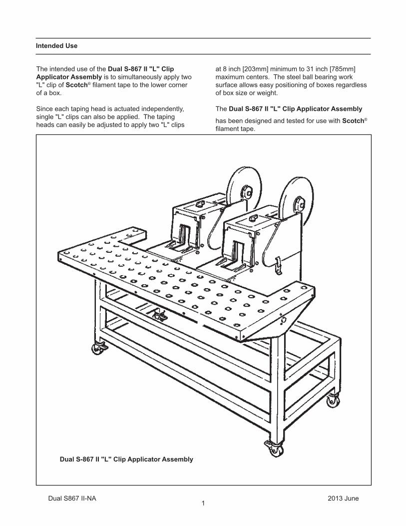
The intended use of the Dual S-867 II "L" Clip Applicator Assembly is to simultaneously apply two "L" clip of Scotch® fi lament tape to the lower corner of a box.
Since each taping head is actuated independently, single "L" clips can also be applied. The taping heads can easily be adjusted to apply two "L" clips
at 8 inch [203mm] minimum to 31 inch [785mm] maximum centers. The steel ball bearing work surface allows easy positioning of boxes regardless of box size or weight.
The Dual S-867 II "L" Clip Applicator Assembly
has been designed and tested for use with Scotch® fi lament tape.
2013 JuneDual S867 II-NA

2
Important Safeguards
This safety alert symbol identif es important messages in this manual.
READ AND UNDERSTAND THEM BEFORE INSTALLING OR OPERATING
THIS EQUIPMENT.
Explanation of Signal Word Consequences
Indicates a potentially hazardous situation, which, if not avoided, could result in death or serious injury and/or property damage.
WARNING:
Indicates a potentially hazardous situation, which, if not avoided, may result in minor or moderate injury and/or property damage.
CAUTION:
• To reduce the risk associated with sharp blade hazards:− Keep hands and fi ngers away from tape cutoff blades under orange blade guards. The blades are extremely sharp• To reduce the risk associated with muscle strain:− Use the appropriate rigging and material handling equipment when lifting or repositioning this equipment
WARNING (continued)
• To reduce the risk associated with pinch and entanglement hazards:− Always feed boxes into the machine by
pushing only from the end of the box− Keep hands, hair, loose clothing, and jewelry
away from opening in the nest
CAUTION
• To reduce the risk associated with mechanical and pneumatic hazards:− Read, understand and follow all safety and operating instructions before operating or servicing the case sealer− Allow only properly trained and qualifi ed personnel to operate and/or service this equipment− Never attempt to defeat the machine guard interlock• To reduce the risk associated with pinch and entanglement hazards:− Turn air supply off and disconnect before performing any adjustments, maintenance or servicing the machine− Turn the machine off while not in use− Never attempt to work on any part of the machine or load tape while the machine is running
WARNING
Important – In the event the following safety labels are damaged or destroyed, they must be replaced to ensure operator safety. Replacement part numbers for individual labels are shown in "Important Safeguards," at the beginning of Section II.
2013 JuneDual S867 II-NA

3
Specifications
1. Tape:
Scotch® fi lament tape.
2. Tape Width:
3/8 inch [9mm], to 1-1/2 inch [36mm].
3. Tape Roll Diameter:
Up to 15 inches [115mm] maximum on a 3 inch [76.2mm] diameter core.
4. Applied Tape Length:
4-1/2 inches [115mm] (nominal). Tape legs are 2-1/4 inches ±1/8 inch [55mm ±3.2mm].
5. Box Size Capacity (Applying two "L" Clips):
Height – 2-1/4 inches [60mm] minimum to unlimited maximum. Width – 13 inches [330mm] minimum to unlimited maximum (Single clip application requires 3-1/4 inch [85mm] minimum box width.) Depth – 2-1/4 inches [60mm] minimum to unlimited maximum
Note – Operator capability will determine maximum height, width and depth. For other size requirements, please contact your 3M sales representative.
6. Cycle Time:
1.2 seconds
7. Compressed Air Requirements:
65 PSIG [4.2 bar gauge pressure] 4.3 SCFM [120 liter/minute @ 21C, 1.0 bar] at 50 cycles/minute
8. Operating Conditions:
Use in dry, relatively clean environments at 40°F to 120°F [5°C to 49°C] with clean, dry boxes.
Note – Machine should not be washed down or subjected to conditions causing moisture condensation on components.
9. Weight:
275 pounds [125 kg] unpackaged 350 pounds [160 kg] packaged (continued)
2013 JuneDual S867 II-NA
4
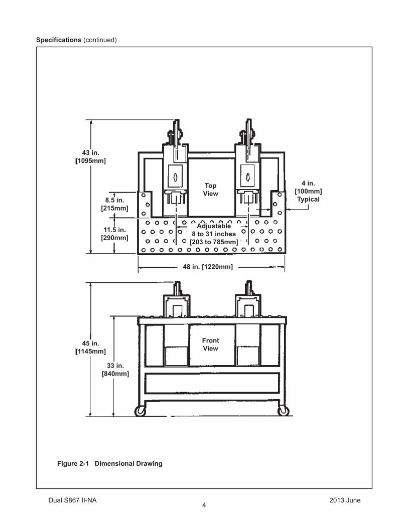
Figure 2-1 Dimensional Drawing
Specifications (continued)
43 in.[1095mm]
45 in.[1145mm]
33 in.[840mm]
48 in. [1220mm]
TopView
FrontView
Adjustable8 to 31 inches
[203 to 785mm]
8.5 in.[215mm]
4 in.[100mm]Typical
11.5 in.[290mm]
2013 JuneDual S867 II-NA

5
Installation and Set-Up
Receiving And Handling
Examine the "L" Clip Applicator Assembly for damage that may have occurred during transit. If damage is evident, fi le a damage claim immediately with the transportation company and also notify your 3M representative.
Machine Set-Up
1. Level machine by shimming under casters if necessary. Machine must be level or boxes left on machine will roll off.
2. Turn air valve on both applicators "Off" and connect plant air supply to male quick disconnect on the lower/rear frame rail of the applicator frame. See Figure 3-1.
Figure 3-1 Air Connection
Initial Start-Up of the Dual S-867 Applicator
After completing the "Set-Up" procedure, continue through "Operation" section of this manual for tape loading/threading and to be sure machine operates properly.
2013 JuneDual S867 II-NA
Air Supply
S867Connection

6
Operation
1. Tape Loading/Threading – See Section II.
2. Turn plant air supply and both applicator air valves "On".
3. Adjust spacing of applicators – Loosen lock knob at front of each applicator (under work table) and slide applicators to desired spacing, then lock in place by tightening lock knob.
Adjustments – See Section II of this manual.
Maintenance – See Section II of this manual.
Troubleshooting – See Section II of this manual.
Adjustments/Maintenance/Troubleshooting
4. Push box forward over both applicator paddle stops and against box paddle, hold box fi rmly in applicator nests to allow application of tape "L" clips. Tape application takes 1/4 second, then box can be removed from machine nests while applicators complete their cycle. Total cycle time 1.2 seconds.
• To reduce the risk associated with mechanical and pneumatic hazards:− Read, understand and follow all safety and operating instructions before operating or servicing the case sealer− Allow only properly trained and qualifi ed personnel to operate and/or service this equipment− Never attempt to defeat the machine guard interlock• To reduce the risk associated with pinch and entanglement hazards:− Turn air supply off and disconnect before performing any adjustments, maintenance or servicing the machine• To reduce the risk associated with sharp blade hazards:− Keep hands and fi ngers away from tape cutoff blades under orange blade guards. The blades are extremely sharp• To reduce the risk associated with muscle strain:− Use the appropriate rigging and material handling equipment when lifting or repositioning this equipment
WARNING
2013 JuneDual S867 II-NA
7
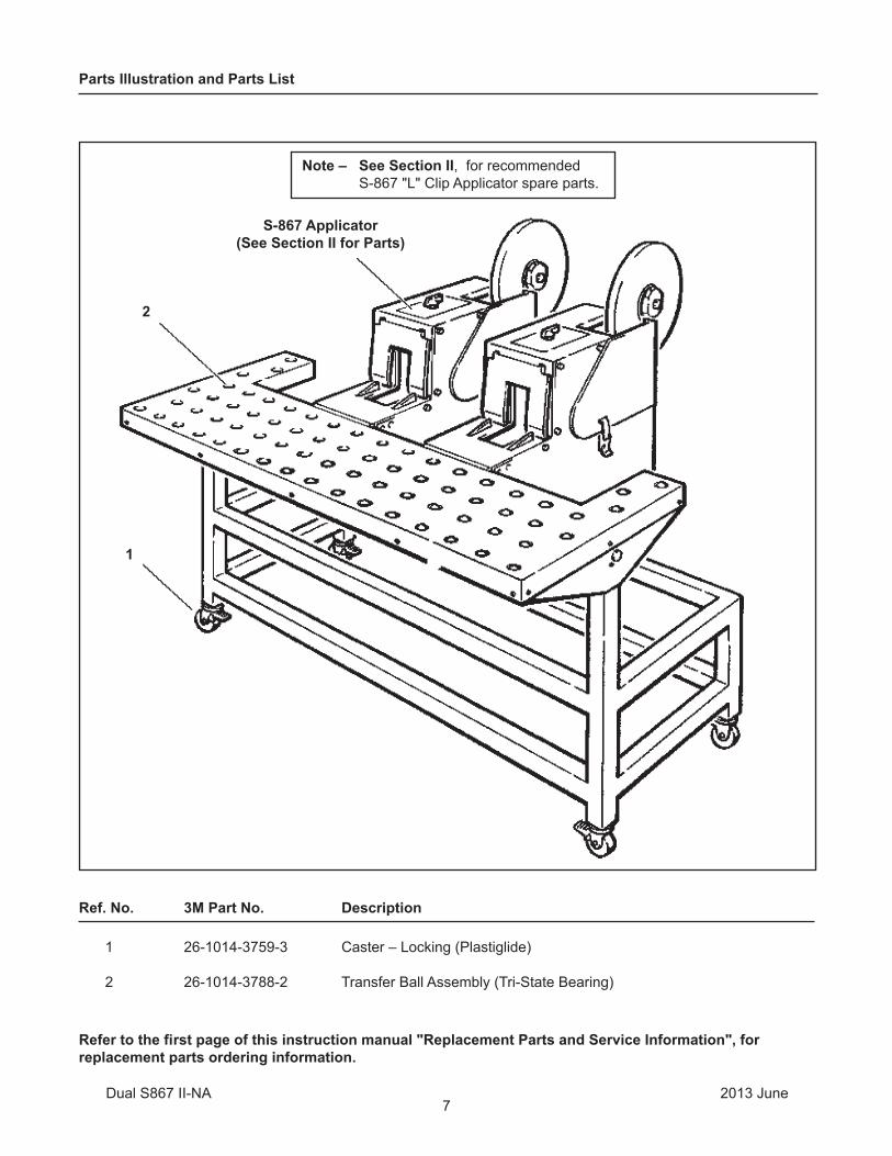
Parts Illustration and Parts List
Note – See Section II, for recommended S-867 "L" Clip Applicator spare parts.
Ref. No. 3M Part No. Description
1 26-1014-3759-3 Caster – Locking (Plastiglide)
2 26-1014-3788-2 Transfer Ball Assembly (Tri-State Bearing)
Refer to the first page of this instruction manual "Replacement Parts and Service Information", for replacement parts ordering information.
S-867 Applicator(See Section II for Parts)
1
2
2013 JuneDual S867 II-NA

8
THIS PAGE IS BLANK

Instructions and Parts List
S867 Type 10500
"L" ClipApplicator(Section II)
Serial No. For reference, record machine serial number here.
Important SafetyInformation
Spare Parts
3M-Matic™
BEFORE INSTALLING OR OPERATING THIS EQUIPMENTRead, understand, and follow all safety and operating instructions.
It is recommended you immediately order the spare parts listed in the "Spare Parts/Service Information" section. These parts are expected to wear through normal use, and should be kept on hand to minimize production delays.
3M Industrial Adhesives and Tapes3M Center, Building 220-5E-06St. Paul, MN 55144-1000
3M-Matic™and AccuGlide™ are Trademarks of 3M, St. Paul, MN 55144-1000Printed in U.S.A© 3M 2013 44-0009-2041-1 (F060713-NA)

This instruction manual covers safety aspects, handling and transport, storage, unpacking, preparation, installation, operation, adjust-ments, maintenance, troubleshooting, repair work and servicing plus parts list of the 3M-Matic S867 L-Clip Applicator.
3M Industrial Adhesives and Tapes3M Center, Building 220-5E-06St. Paul, MN 55144-1000
Edition June 2013
Copyright 3M 2013All rights reserved
The manufacturer reserves the right to change the product at any time without notice.

1
3M-Matic™, AccuGlide™ and Scotch™ are Trademarks of 3M St. Paul, MN 55144-1000Printed in U.S.A.
3M Industrial Adhesives and Tapes3M Center, Building 220-5E-06St. Paul, MN 55144-1000
To Our Customers:
This is the 3M-Matic™/AccuGlide™/Scotch® equipment you ordered. It has been set up and tested in the factory with Scotch® tapes. If technical assistance or replacement parts are needed, call or fax the appropriate number.
Included with each machine is an Instructions and Parts List manual.
Technical Assistance / Replacement Parts and Additional Manuals:
Contact your local service provider. Provide the customer support coordinator with the model/machine name, machine type, and serial number that are located on the identification plate (For example: Model S867 - Type 40800 - Serial Number 13282).
Identification Plate
Replacement Parts and Service Information
i

To Our Customers:
This is the 3M-Matic™/AccuGlide™/Scotch® equipment you ordered. It has been set up and tested in
the factory with Scotch® tapes. If technical assistance or replacement parts are needed, call or fax the
appropriate number listed below.
Included with each machine is an Instructions and Parts List manual.
Replacement Parts and Additional Manuals
Order parts by part number, part description, and quantity required.
When ordering parts or additional manuals, include model/machine name,
machine type, and serial number that are located on the identifi cation plate
(For example: S867 L-Clip Applicator - Type 10500 - Serial Number 13282).
3M Tape Dispenser Parts
241 Venture Drive 1-800-344-9883
Amery, WI 54001-1325 Fax: 1-715-268-8153
Technical Assistance:
Call the 3M-Matic™ Helpline at 1-800-328-1390. Provide the customer support coordinator
with the model/machine name, machine type, and serial number that are located on the
identifi cation plate . If you have a technical question that does not require an immediate
response, you may fax it to 1-651-736-7282.
3M-Matic™, AccuGlide™ and Scotch™ are Trademarks of 3M, St. Paul, MN 55144-1000
Printed in U.S.A.
3M Industrial Adhesives and Tapes3M Center, Building 220-5E-06St. Paul, MN 55144-1000
Minimum billing on parts orders will be $25.00. Replacement part prices available on request.
Note : Outside the U.S., contact the local 3M subsidiary for parts ordering information.$10.00 restocking charge per invoice on returned parts.
Replacement Parts and Service Information
ii

(Table of Contents continued on next page)
2013 JuneS867-NA iii
TABLE OF CONTENTS: S-867 “L” Clip Applicator, Type 10500
S-867 “L” Clip Applicator Page
Cover Page Replacement Parts and Service Information ........................................................................ i-ii Table of Contents ................................................................................................................. iii-iv Acronyms and Abbreviations ................................................................................................ v
1. Introduction
1.1 Intended Use .............................................................................................................. 1 1.2 How to Read and Use the Manual ............................................................................... 2 1.2.1 Importance of the Manual .................................................................................. 2 1.2.2 Manual Maintenance ......................................................................................... 2 1.2.3 Consulting the Manual ........................................................................................ 2 1.2.4 How to Update the Manual in Case of Modifi cations .......................................... 2
2. General Information
2.1 Identifi cation Data ........................................................................................................ 3 2.2 Warranty / Contents ..................................................................................................... 4
3. Important Safeguards
3.1 Signal Words Explanation ............................................................................................. 5 3.2 Table of Warnings ......................................................................................................... 5 3.3 Operator’s Qualifi cations Defi nition ............................................................................. 6 3.4 Table of Warnings and Replacement Labels ............................................................... 7
4. Technical Specifications
4.1 Tape Specifi cations ................................................................................................... 8 4.2 Air Power Requirements ............................................................................................... 8 4.3 Box Size Capacity ................................................................................................... 8 4.4 Cycle Time .................................................................................................................... 8 4.5 Operating Conditions ................................................................................................... 8 4.6 Machine Dimensions ................................................................................................... 8
5. Installation and Set-Up
5.1 Receiving and Handling ................................................................................................ 9 5.2 Machine Set-Up ............................................................................................................ 9 5.3 Mounting ...................................................................................................................... 9 - 10 5.4 Air Regulator / Filter ...................................................................................................... 11 5.5 Tape Drum - Bracket Assembly .................................................................................... 12

4
THIS PAGE IS BLANK

iv
TABLE OF CONTENTS (continued)
2013 JuneS867-NA
6. Theory of Operation
6.1 General Information ................................................................................................ .......13 6.2 Operational Explanation ................................................................................................ 13 Rest Position, Air Off .................................................................................................... 13 Rest Position, Air On ..................................................................................................... 13 Application Cycle, Cut / Buff Sequence ......................................................................... 14 Application Cycle, Feed Sequence ............................................................................. 15 6.3 Components ...................................................................................................................16 Valves .................................................................................................... ......................16 Cylinders .................................................................................................... ..................16
7. Operation
7.1 Tape Loading and Threading ........................................................................................ 17 7.2 Operating Sequence ..................................................................................................... 18
8. Adjustments
8.1 Tape Width .......................................................................................... .........................19 8.2 Tape Web Alignment ............................................................................................. ........19 8.3 Tape Drum Tension ........................................................................................................ 19 8.4 Tape Tension Roller ............................................................................. .........................19 8.5 V-8 Valve Adjustment ............................................................... ....................................19 8.6 Air Flow Controls ................................................................................................... .......19
9. Maintenance
9.1 Blade Replacement ................................................................................................... ...20 9.2 Air Line Filter ............................................................................................... ..................20
10. Troubleshooting
10.1 Pneumatic Schematic ................................................................................................ ....21 10.2 Troubleshooting Guide ............................................................................................... ...22 - 23 10.3 Air Line Connections / Tubing Length ............................................................................ 24
11. Replacement Parts and Service Information
11.1 Recommended Spare Parts .......................................................................................... 26 11.2 How To Order Replacement Parts ................................................................................. 26 11.3 Repair Service .............................................................................. .................................26
Drawings and Parts Lists ................................................................................................... 27 - 46
12. Typical Mounting Set-Up / Single Head Stand
12.1 Purpose of Attachment .................................................................................................. 47
13. Specifications
13.1 Parts .......................................................................................... ...................................47 13.2 Overall Dimensions ............................................................................................. ..........47 13.3 Work Surface Height ................................................................................................... ..47 13.4 Work Surface Size............................................................................ ..............................47 13.5 Work Surface Weight ............................................................... ......................................47
14. Assembly Instructions
14.1 Single Head Stand ................................................................................................ ........48 - 49 14.2 Work Surface Height .......................................................................................... ..........49 14.3 Instructions .............................................................................. ......................................49 14.4 Warranty .............................................................................. .........................................51

2013 JuneS867-NA
ABBREVIATIONS AND ACRONYMS
v
LIST OF ABBREVIATIONS AND ACRONYMS
3M-Matic - Trademark of 3M St. Paul, MN 55144-1000
Scotch - Trademark of 3M St. Paul, MN 55144-1000 Drw. - drawing
Ex. - for example
Fig. - exploded view fi gure no. (spare parts)
Figure - Illustration Max. - maximum
Min. - minimum
Nr. - number
N/A - not applicable
OFF - machine not operating ON - machine operating
PLC - Programmable Logic Control
PP - Polypropylene
PTFE - Polytetrafl ourethelene
PU / PU-Foam - Polyurethane Foam
PVC - Poly-vinyl chloride
W - Width
H - Height
L - Length

1
1.1 Intended Use:
The intended use of the S-867 "L" Clip Applicator is to apply an "L" clip of Scotch® fi lament tape to most box corners.
The machine is designed for installation adjacent to a conveyor system or on a stand for off-line systems, the S-867 allows the operator to quickly apply the "L" clip box closure. When a box is inserted into the
1 - Introduction
nest, the product paddle is depressed and the air operating mechanism which applies the "L" clip tape closure is activated causing the "L" clip to be automatically applied to the box corner.
The S-867 "L" Clip Applicator has been designed and tested for use with Scotch® fi lament and strapping tape.
3M-Matic™ S-867 "L" Clip Applicator, Type 10500
2013 JuneS867-NA
2 2013 JuneS867 - NA
1 - Introduction (continued)
1.2.2 Manual Maintenance
Keep the manual in a clean and dry place near the machine. Do not remove, tear, or rewrite parts of the manual for any reason. Use the manual without damaging it. In case the manual has been lost or damaged, ask your after-sale service for a new copy.
1.2.3 Consulting the Manual
The manual is composed of:
- Pages which identify the document and the machine- Index of the subjects- Instructions and notes on the machine- Enclosures, drawings and diagrams- Spare parts (last section)
All pages and diagrams are numbered. The spare parts lists are identifi ed by the fi gure identifi cation number. All the notes on safety measures or possible dangers are identifi ed by the symbol:
1.2.4 How to Update the Manual in Case of Modifications to the Machine
Modifi cations to the machine are subject to manufacturer’s internal procedures. The user receives a complete and up-to-date copy of the manual together with the machine. Afterwards the user may receive pages or parts of the manual which contain amendments orimprovements made after its fi rst publication. The user must use them to update this manual.
1.1 Manufacturing Specifications / Description / Intended Use (continued)
The 3M-MaticTM case sealing machines have beendesigned and manufactured in compliance with the legal requirements at the date of inception.
1.2 How to Read and Use the Instruction Manual
This instruction manual covers safety aspects, handling and transport, storage, unpacking, preparation, installation, operation, Setup and adjustments, technical and manufacturing specifi ca-tions, maintenance, troubleshooting, repair work and servicing, electric diagrams, warranty information, disposal (ELV), a defi nition of symbols, plus a parts list of the 3M-MaticTM S-867 "L" Clip Applicator 3M Industrial Adhesives and Tapes Division 3M Center, Bldg. 220-5E-06 St. Paul, MN 55144-1000 (USA) Edition June 2013 Copyright 3M 2010 All rights reserved. The manufacturer reserves the right to change the product at any time without notice. Publication © 3M 2013 44-0009-2041-1.
1.2.1 Importance of the Manual
The manual is an important part of the machine; all information contained herein is intended to enable the equipment to be maintained in perfect condition and operated safely. Ensure that the manual is available to all operators of this equipment and is kept up to date with all subsequent amendments. Should the equipment be sold or disposed of, please ensure that the manual is passed on. Electrical and pneumatic diagrams are included in the manual. Equipment using PLC controls and/or electronic components will include relevant schematics or programs in the enclosure and in addition, the relevant documentation will be delivered separately.

3 2013 June
2.1 Data Identifying Manufacturer and Machine
2 - General Information
S867 - NA
Identification Plate

4 2013 JuneS867-NA
2 - General Information (continued)
Contents—L-Clip Applicator
(1) S-867 "L" Clip Applicator, Type 10500 (1) Instruction and Parts Manual
2.2 Warranty
Equipment Warranty and Limited Remedy: THE FOLLOWING WARRANTY IS MADE IN LIEU OF ALL OTHER WARRANTIES, EXPRESS OR IMPLIED, INCLUDING, BUT NOT LIMITED TO, THE IMPLIED WARRANTY OF MERCHANTABILITY, THE IMPLIED WARRANTY OF FITNESS FOR A PARTICULAR PURPOSE AND ANY IMPLIED WARRANTY ARISING OUT OF A COURSE OF DEALING, A CUSTOM OR USAGE OF TRADE:
3M sells its 3M-Matic™ S-867 "L" Clip Applicator , Type 10500 with the following warranties:
1. The drive belts and the taping head knives, springs and rollers will be free from all defects for ninety (90) days after delivery.2. All other taping head parts will be free from all defects for three (3) years after delivery. 3. All other parts will be free from all defects for two (2) years after delivery.
If any part is proved to be defective within its warranty period, then the exclusive remedy and 3M’s and seller’s sole obligation shall be, at 3M’s option, to repair or replace the part, provided the defective part is returned immediately to 3M’s factory or an authorized service station designated by 3M. A part will be presumed to have become defective after its warranty period unless the part is received or 3M is notifi ed of the problem no later than fi ve (5) calendar days after the warranty period. If 3M is unable to repair or replace the part within a reasonable time, then 3M at its option, will replace the equipment or refund the purchase price. 3M shall have no obligation to provide or pay for the labor required to install the repaired or replacement part. 3M shall have no obligation to repair or replace (1) those parts failing due to operator misuse, carelessness, or due to any accidental cause other than equipment failure, or (2) parts failing due to non-lubrication, inadequate cleaning, improper operating environment, improper utilities or operator error.
Limitation of Liability: 3M and seller shall not be liable for direct, indirect, special, incidental or consequential damages based upon breach of warranty, breach of contract, negligence, strict liability or any other legal theory.
The foregoing Equipment Warranty and Limited Remedy and Limitation of Liability may be changed only by a written agreement signed by authorized offi cers of 3M and seller.

5
3 - Important Safeguards
• To reduce the risk associated with mechanical and pneumatic hazards: − Read, understand and follow all safety and operating instructions before operating or servicing the case sealer − Allow only properly trained and qualifi ed personnel to operate and/or service this equipment − Never attempt to defeat the machine guard interlock • To reduce the risk associated with pinch and entanglement hazards: − Turn air supply off and disconnect before performing any adjustments, maintenance or servicing the machine − Turn the machine off while not in use − Never attempt to work on any part of the machine or load tape while the machine is running
• To reduce the risk associated with sharp blade hazards: − Keep hands and fi ngers away from tape cutoff blades under orange blade guards. The blades are extremely sharp • To reduce the risk associated with muscle strain:
− Use the appropriate rigging and material handling equipment when lifting or repositioning this equipment
• To reduce the risk associated with pinch and entanglement hazards:
− Always feed boxes into the machine by pushing only from the end of the box
− Keep hands, hair, loose clothing, and jewelry away from opening in the nest
2013 JuneS867-NA
3.1 Explanation of Signal Word and Possible Consequences
3.2 Table of Warnings
Indicates a potentially hazardous situation, which, if not avoided, may result in minor or moderate injury and/or property damage.
CAUTION:
Indicates a potentially hazardous situation, which, if not avoided, could result in death or serious injury and/or property damage.
WARNING:
This safety alert symbol identifi es important messages in this manual.READ AND UNDERSTAND THEM
BEFORE INSTALLING OR OPERATING THIS EQUIPMENT.
WARNING
WARNING (continued)
CAUTION

6
Skill 1 - Machine Operator This operator is trained to use the machine with the machine controls, to feed cases into the machine, to change the tape and to start, stop and restart production.
Important – the factory manager must ensure that the operator has been properly trained on all the machine functions before starting work.
3 - Important Safeguards (continued)
Skill 2 - Mechanical Maintenance Technician This operator is trained to use the machine as the MACHINE OPERATOR and in addition is able to work with the safety protection disconnected, to check and adjust mechanical parts, to carry out maintenance operations and repair the machine.
Skill 3 - Specialist From the Manufacturer Skilled operator sent by the manufacturer or its agent to perform complex repairs or modifi cations, when agreed with the customer.
Operation State of the MachineOp-
erator's Skill
Number of Op-erators
Installation and set up of the machine.
Running with safety protections disabled. 2 1
Tape replacement. Main air valve in the "off" position or air supply disconnected. 1 1
Replacement of blades. Air supply disconnected. 2 1
Ordinary maintenance. Air supply disconnected. 2 1
Extraordinary maintenance (me-chanical).
Running with safety protections disabled. 3 1
Operator Skill Level Descriptions
Operator's Skill Levels Required to Perform the Main Operations on Machine
• To reduce the risk associated with mechanical and pneumatic hazards: − Read, understand and follow all safety and operating instructions before operating or servicing the case sealer − Allow only properly trained and qualifi ed personnel to operate and/or service this equipment
2013 JuneS867-NA
WARNING
3.3 Operator Qualif cations

7
3 - Important Safeguards (continued)
Figure 3-1 Replacement Labels/3M Part Numbers78-8133-9648-4
Valve Label(not shown)
78-8119-6596-7
Important – In the event the following safety labels are damaged or destroyed, they must be replaced to ensure operator safety. Replacement part numbers for individual labels are shown in Figure 3-1, or a label kit part number 78-8137-0223-6, is available that includes all labels used on the machine.
2013 JuneS867-NA
78-8133-9643-5
78-8133-9656-7
78-8119-6594-2
78-8119-6598-3
78-8119-6595-5
3.4 Table of Warnings and Replacement Labels

8
4 - Specifications
4.4 Cycle Time:
1.2 seconds per cycle
The cycle time is suffi cient to satisfy the majority of applications. Flow controls (see Machine Setup and Adjustments section) control the application rate and return stroke rate of the buffi ng and tape feed air cylinders. While these fl ow controls can be adjusted for increased speed, this practice may result in higher maintenance costs and shorten machine life.
4.1 Tape Specifications:
Tape – Most "Scotch" brand fi lament tapes.
Tape Width – 3/8 inch [9mm] to 1 1/2 inch [36mm].
Tape Roll Diameter – Up to 15 inches [380mm] maximum on a 3 inch [76.2mm] diameter core.
Applied Tape Length – 4 1/2 inches [115mm] (nominal). Tape legs are 2 1/4 ±1/8 inches[55 mm ± 3.2mm].
4.2 Air Power Requirements:
60 to 65 PSIG [415 to 450 kPa] gauge pressure.
2.16 SCFM [3.65 m3/h 21°C, 101 kPa] at 50 cycles/min
4.5 Operating Conditions:
Use in dry, relatively clean environments at 40° to 120°F [5° to 49°C] with clean, dry boxes.
Important – Machine should not be washed down or subjected to conditions causing moisture condensation on components.
4.6 Machine Dimensions:
Length – 31 inches [790mm] (includes 360 yard [330m] tape roll)
Height – 29 inches [735mm] (includes 360 yard [330m] tape roll)
Width – 11 inches [280mm]
Weight – Packaged 83 lb [37.7 kg] Unpackaged 75 lb [34 kg]
4.3 Box Size Capacity:
Bottom or Top Taping Position Height – 2 1/4 inches [60mm] minimum to
unlimited maximum
Width – 3 inches [75mm] minimum to unlimited maximum
Depth – 2 1/4 inches [60mm] minimum to unlimited maximum
Note: Operator capability will determine maximum height, width, and depth. Smaller heights and widths are sometimes possible and it is recommended that your 3M Representative be contacted for testing of these applications.
2013 JuneS867-NA
9
5.1 Receiving and Handling
After the applicator has been unpacked, examine it thoroughly for any damage that may have occurred during transit. If damage is evident, f le a damage claim immediately with the transportation company and also notify your 3M Representative.
5.2 Machine Set-Up
Read the installation instructions through completely before performing the set-up procedure. Refer to the back of this manual for literature on "Typical Mounting Set-Up" for the S-867 Applicator.
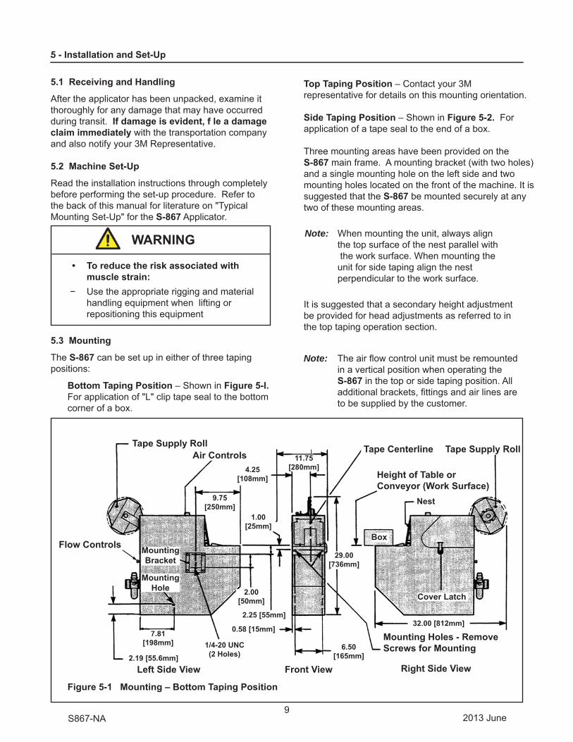
5.3 Mounting
The S-867 can be set up in either of three taping positions:
Bottom Taping Position – Shown in Figure 5-l. For application of "L" clip tape seal to the bottom corner of a box.
5 - Installation and Set-Up
Top Taping Position – Contact your 3M representative for details on this mounting orientation.
Side Taping Position – Shown in Figure 5-2. For application of a tape seal to the end of a box.
Three mounting areas have been provided on the S-867 main frame. A mounting bracket (with two holes) and a single mounting hole on the left side and two mounting holes located on the front of the machine. It is suggested that the S-867 be mounted securely at any two of these mounting areas.
Note: When mounting the unit, always align the top surface of the nest parallel with the work surface. When mounting the unit for side taping align the nest perpendicular to the work surface.
It is suggested that a secondary height adjustment be provided for head adjustments as referred to in the top taping operation section.
Note: The air fl ow control unit must be remounted in a vertical position when operating the S-867 in the top or side taping position. All additional brackets, fi ttings and air lines are to be supplied by the customer.
• To reduce the risk associated with muscle strain:− Use the appropriate rigging and material
handling equipment when lifting or repositioning this equipment
2013 JuneS867-NA
WARNING
Tape Supply Roll Tape Centerline Tape Supply Roll Air Controls
Flow Controls
Left Side View Front View Right Side View
Mounting Holes - Remove Screws for Mounting
Height of Table orConveyor (Work Surface)
MountingBracket
1/4-20 UNC(2 Holes)
2.00[50mm]
7.81[198mm]
1.00[25mm]
MountingHole
2.25 [55mm]32.00 [812mm]
2.19 [55.6mm]
0.58 [15mm]
Cover Latch
Box
Nest9.75[250mm]
11.75[280mm]4.25
[108mm]
29.00[736mm]
6.50[165mm]
Figure 5-1 Mounting – Bottom Taping Position

10
5 - Installation and Set-Up (continued)
Figure 5-2 Mounting Side Taping Position – Front View
2013 JuneS867-NA
Tape Centerline
Mounting Bracket
Front View
1/4-20 UNC Mounting Holes - Remove Screws for Mounting
1/4-20 UNC (2 Holes)
2.00 [50mm]
7.75[197mm]
1.00 [25mm]
2.25 [55mm]
0.58 [15mm]4.25
[108mm]
6.50[165mm]

11
5 - Installation and Set-Up (continued)
5.4 Air Regulator / Filter
The air control unit is supplied with two (2) mount-ing screws. Install the unit on the main frame, lower rear side, in the mounting holes provided.
1. Refer to Figure 5-3 and locate the air control unit (A) in a vertical position for proper operation. Assemble and secure the two 8-32 x 1/2 lg. screws and fl at washers.
2. Refer to Figure 5-4 and push the air line (B) onto the male elbow (C) on the right side of the air control unit as shown.
3. Connect main air supply line.
Note: The main air supply line and required fi ttings are to be supplied by customer.
Turn On/Off valve on S-867 to "Off" (O) position. See Figure 5-3.
Connect main air supply line to main air supply inlet on air regulator. See Figure 5-4.
Figure 5-3 Installation – Tape Mounting Bracket and Unwind Hub – Left Rear View
2013 JuneS867-NA
Tape Retainer
On-Off Valve
D F E
A
1 11/16 [43mm]

12
5 - Installation and Set-Up (continued)
2. Assemble the tape drum/backup plate (D) to the bracket (E) and adjust tape drum/backup plate in or out to obtain the 1-11/16 inch [43 mm] clearance between backup plate and bracket as shown in Figure 5-3. Secure this setting with the 1/2-13 jam nut (F).
Tape Loading and Threading
See "Operations Section."
5.5 Tape Drum - Bracket Assembly
The tape drum bracket is supplied with two #10-24 x 1/2 lg mounting screws. Assemble the bracket to the machine and the tape drum to the bracket.
1. Attach the tape drum bracket (E) to the rear of the machine with two #10-24 x 1/2 lg soc hd capscrews as shown in Figure 5-3.
Figure 5-4 Air Control Unit – Set-Up
2013 JuneS867-NA
Air Pressure Adjustment Knob
Main Air Supply Inlet
Pressure Gauge
Air Filter
Drain Valve
B
C

13
6 - Theory of Operation
This section contains general information about the S-867, a pneumatic schematic, detailed operational explanation and a pneumatic components list.
6.1 General Information
The S-867 is a pneumatically powered machine containing eleven pneumatic valves and six pneumatic cylinders. These components are all listed at the end of this section with a brief description of their function.
The machine consists of four primary assemblies listed below.
• Knife assembly – cuts the section of tape to be applied.
• Buff assembly – applies the section of tape to the box corner.
• Feed assembly – advances the tape between applications.
• Jaw assembly – retains the free end of the tape between applications.
6.2 Operational Explanation
Rest Position, Air Off
When the machine is in rest position with the air off, a spring-actuated air cylinder extends to hold up the feed assembly. See Figure 6-1. This is neces-sary because the air cylinder is in the fully extended position. Without the spring-actuated air cylinder, the weight of the feed assembly could cause the air cylinder to retract and damage the section of tape ready for application.
Rest Position, Air On
When air is applied to the machine, it is routed through the On/Off control valve V-1, through line 2, through safety valve V-9, and into the manifold through line 28. See Figure 6-1.
The manifold then routes the air to seven locations. Four of the routes from the manifold direct air to valves that are closed when the machine is in the rest position. These "blocked" air routes are:
• Through line 3 to valve V-2
• Through line 25 to valve V-3
• Through line 24 to valve V-4
• Through line 18 to valve V-6
The remaining three routes direct air to actuate the air cylinders and prepare the machine for the application cycle.
• Air is directed through line 29 to retract the spring-loaded safety cylinder that retains the feed mechanism.
• Air is directed through line 27 to the pilot valve P-1. The air exits the pilot valve and is branched
to retract the buff and cut cylinders. The pilot valve directs air through line 9, the buff cylinder retract fl ow control valve, and line 21 to the rod end of the buff cylinder to retract the cylinder, and through line 8 to the rod end of the cut cylinder and retracts it also.
• Air is also directed through line 7 to pilot valve P-2. The air exits the pilot valve P-2 and is
branched to extend the feed and jaw cylinders. Air travels from the pilot valve through line 14, valve V-5, and line 26 to the head end of the jaw cylinder and extends the cylinder. Air is also directed through line 15, valve V-7, line 19, the feed cylinder extend fl ow control valve, and line 22 to the head-end of the feed cylinder and extends the feed cylinder.
Figure 6-1 Rest Position
2013 JuneS867-NA
Tape Roll
Box
Tape PathFeed AssemblyKnife AssemblyBuffing Assembly

14
6 - Theory of Operation (continued)
Application Cycle, Cut / Buff Sequence
When the machine is in the powered rest position and a box is placed in the nest area, the box paddle actuates valve V-2. This allows a pulse of air to fl ow from the manifold through valve V-2, line 4, valve V-8, and line 5 to the PA port of the pilot valve P-1. This shifts the pilot valve P-1. Air is then directed to the paddle cylinder, which holds the paddle to the machine housing, which prevents the additional actuation of paddle valve V-2 before the application cycle is completed.
Air is then directed to the head end of the cut and buff cylinders and causes both to extend at the same time. At full extension, a section of tape is cut by the knife assembly and immediately applied to the box by the buff roller assembly.
As the buff assembly reaches full extension, it actuates valve V-3. This directs a pulse of air to the PB port of the pilot valve P-1 causing it to shift and direct air to the rod end of the cut and buff cylinders. This causes the cut and buff cylinders to retract and return the knife and buff assemblies back to the ma-chine rest position. Shortly before the buff cylinder fully retracts, it actuates valve V-4. This begins the feed sequence.
Figure 6-2 Cut / Buff Sequence
2013 JuneS867-NA
The Buffing RollersApply the Tape
The Knife Cutsthe Tape
Box
15
6 - Theory of Operation (continued)
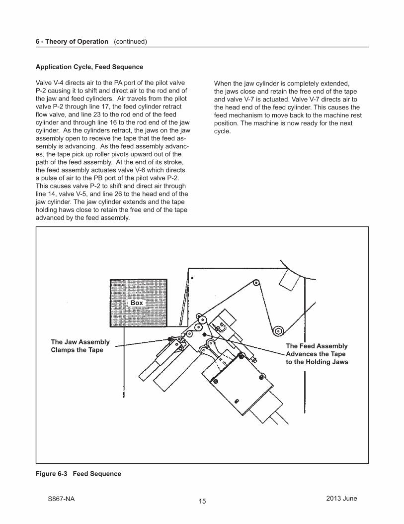
Application Cycle, Feed Sequence
Valve V-4 directs air to the PA port of the pilot valve P-2 causing it to shift and direct air to the rod end of the jaw and feed cylinders. Air travels from the pilot valve P-2 through line 17, the feed cylinder retract fl ow valve, and line 23 to the rod end of the feed cylinder and through line 16 to the rod end of the jaw cylinder. As the cylinders retract, the jaws on the jaw assembly open to receive the tape that the feed as-sembly is advancing. As the feed assembly advanc-es, the tape pick up roller pivots upward out of the path of the feed assembly. At the end of its stroke, the feed assembly actuates valve V-6 which directs a pulse of air to the PB port of the pilot valve P-2. This causes valve P-2 to shift and direct air through line 14, valve V-5, and line 26 to the head end of the jaw cylinder. The jaw cylinder extends and the tape holding haws close to retain the free end of the tape advanced by the feed assembly.
When the jaw cylinder is completely extended, the jaws close and retain the free end of the tape and valve V-7 is actuated. Valve V-7 directs air to the head end of the feed cylinder. This causes the feed mechanism to move back to the machine rest position. The machine is now ready for the next cycle.
Figure 6-3 Feed Sequence
2013 JuneS867-NA
The Jaw AssemblyClamps the Tape The Feed Assembly
Advances the Tapeto the Holding Jaws
Box

16
6 - Theory of Operation (continued)
6.3 Components
Refer to Figure 6-1 for component locations.
Valves
V-1: The on/off control valve, actuated by the knob on the top of the machine.
V-2 Paddle Valve: A box placed in the paddle area actuates V-2, which directs a pulse of air from the manifold, through valve V-8, to the PA port of pilot valve P-1. This shifts valve P-1 and activates the buff and cut cylinders beginning the application cycle.
V-3: This valve is actuated by an actuator on the buff cylinder slide assembly and directs air to the PB inlet of valve P-1, thus causing it to shift and retract the buff and cut cylinders.
V-4: This valve is actuated by an actuator on the buff cylinder slide assembly and routes air to the PA port of the pilot valve P-2. This causes valve P-2 to shift and direct power to the feed and jaw cylinders to begin the feed sequence.
V-5: Actuated by the buff cylinder slide assembly at the end of the retract stroke, V-5 directs air from the pilot valve V-2 to the jaw cylinder.
V-6: Actuated by the feed cylinder slide assembly at the end of the retract stroke, V-6 shifts the pilot valve P-2 and causes extension of the jaw cylinder. This causes the tape holding jaws to close on the free end of the tape.
V-7: Valve V-7 is actuated by the actuator mounted on the jaw cylinder rod. When the jaw cylinder fully extends, valve V-7 actuates and directs air to the head-end of the feed cylinder, causing the feed cylin-der retract. This completes the feed cycle.
V-8: Actuated by the full extension of the feed cylin-der assembly, valve V-8 provides a path for air from paddle valve V-2 to pilot valve P-1. This sets up the machine for the application cycle.
V-9: Safety Valve: V-9 removes power (air) to the machine when the cover is opened.
P-1 Pilot Valve: P-1 controls the buff/cut sequence.
P-2 Pilot Valve: P-2 controls the feed sequence.
Cylinders
Safety Cylinder: A spring loaded cylinder that retains the feed assembly when the machine is in the rest position-power off.
Paddle Cylinder: A cylinder which is actuated at the beginning of the application cycle. It holds the box paddle beyond the actuation point of paddle valve V-2, to prevent additional actuation of the paddle valve before the application cycle ends.
Buff Cylinder: The buff cylinder controls the buff roller assembly the "L" clip of tape to the box corner.
Cut Cylinder: The cut cylinder controls the knife assembly that cuts the section of tape applied by the buff roller assembly.
Feed Cylinder: The feed cylinder controls the feed assembly that advances the tape and inserts it into the holding jaws immediately following the buff/cut sequence.
Jaw Cylinder: The jaw cylinder controls the holding jaws that retain the end of the tape between applications.
Air Flow Control Valves
F-1: Flow Control Valve 1 controls the extend rate of the feed cylinder. This is needed to prevent premature wear and damage to machine components.
F-2: Flow Control Valve 2 controls the retract rate of the feed cylinder. This is needed to prevent premature wear and damage to machine components.
F-3: Flow Control Valve 3 controls the retract rate of the buffi ng cylinder. This is needed to prevent premature wear and damage to machine components.
F-4: Flow Control Valve 4 controls the extend rate of the buffi ng cylinder. This is needed to ensure the tape is cut prior to being applied to the product.
2013 JuneS867-NA

17
7.1 Tape Loading and Threading
The tape drum assembly is set up for dispensing 3/8 inch [9mm] or 1/2 inch [12mm] wide tape. For dispensing other tape widths refer to "Adjustments – Tape Width." A tape threading diagram is located outside the applicator on the top of the nest for quick reference.
7 - Operation
• To reduce the risk associated with mechanical and pneumatic hazards:− Read, understand and follow all safety and operating instructions before operating or servicing the
case sealer− Allow only properly trained and qualifi ed personnel to operate and/or service this equipment
For easy access to tape loading and threading, open the cover located on the right side of the S-867. Release the cover latch, shown in Figure 7-1, pull outward on the upper part of the latch, unhook the latch and pivot open the cover.
Refer to Figure 7-1 and thread the tape as follows:
1. Place the tape roll on the tape drum so the tape is dispensed downward, adhesive side forward. The tape roll must be fully against the drum fl ange.
2. Pull approximately 12 inches [300mm] of tape from the roll and thread the tape under the tension roller, adhesive side up.
• To reduce the risk associated with mechanical and pneumatic hazards:− Never attempt to defeat the machine guard interlock
• To reduce the risk associated with pinch and entanglement hazards:− Turn air supply off and disconnect before performing any adjustments, maintenance or servicing
the machine or taping heads
Figure 7-1 Tape Loading and Threading – Right Side View
2013 JuneS867-NA
WARNING
WARNING
On-Off Valve
Box Paddle
Nest
Paddle Stop
Wrap Roller
One-Way Roller
Tension Roller
Tape Adhesive Side
Take-Up Roller
Tape Supply Roll
Top WrapRoller
Tape SupportShaft
Tape Pick-UpRoller

18
7 - Operation (continued)
3. Bring the tape up over the take-up roller, adhesive side up.
7. Turn “On” (I) the main air supply at the on/off valve.
8. To clear the tape which has been tacked to the nest, manually holding the paddle stop down and push the box paddle in to cycle the unit. The applicator is ready to operate.
4. Thread the tape over the top wrap roller, around the one way roller assembly, over the wrap roller, adhesive side toward the nest, begin tape down behind the tape holding roller and also the tape pick-up roll.
Note: To simplify the tape threading at the next reloading, replace with a new roll of "Scotch" brand fi lament tape, and splice the tape web together at the tension roller.
5. Pull out enough tape to tack it to the top of the nest as shown.
6. Close the cover and secure the latch.
Note: Remove all work tools, etc. from inside S-867 case before closing cover.
7.2 Operating Sequence
1. Move the box forward over the paddle stops, depressing the box paddle and hold it fi rmly and squarely against the nest vertical surface to apply the tape.
2. The application only takes 1/4 second to apply the tape, then the box can be removed from the nest while the machine continues to complete the cycle.
• To reduce the risk associated with sharp blade hazards:− Keep hands and fi ngers away from
tape cutoff blades under orange blade guards. The blades are extremely sharp
CAUTION
CAUTION
• To reduce the risk associated with pinch and entanglement hazards:− Always feed boxes into the machine by
pushing only from the end of the box
• To reduce the risk associated with pinch and entanglement hazards:− Keep hands, hair, loose clothing, and
jewelry away from the opening in the nest
2013 JuneS867-NA
WARNING

19
8 - Adjustments
8.1 Tape Width
The tape drum is assembled at the factory for 3/8 inch [9mm] or 1/2 inch [12mm] wide tapes. For 5/8 inch [15mm] tapes the retainers must be moved to the secondary position on the tape drum. This is done by removing the two screws and relo-cating the retainer, then replacing and securing the screws.
8.2 Tape Web Alignment
The tape drum assembly controls tape web alignment in the applicator. Adjust the tape drum assembly so the tape web is dispensed, centered on the buffi ng rollers.
8.3 Tape Drum Tension
The tape drum assembly provides a preset tape roll tension to control over-travel. The tape drum tension requires no further adjustment.
8.4 Tape Tension Roller
The tension roller assembly, shown in Figure 8-1, provides a preset tension to the tape web. No further adjustment is required. If the tension roller assembly is replaced or comes out of adjustment, make adjustment as follows to obtain tension to the tape web: turn the lock nut, located behind the tension roller assembly, counterclockwise to increase tension, clockwise to decrease tension.
8.5 V-8 Valve Adjustment
The V-8 Valve is fully engaged (at the top of it's travel) and properly adjusted when the cam roller arm is in a parallel position to the valve body (see Figure 8-1). Loosen valve adjustment screws (2), slide valve up or down to obtain this adjustment and tighten screws. Be sure feed assembly is held at top of travel when making valve adjustment.
8.6 Air Flow Controls (Figure 8-2)
There are four air fl ow control valves on the S-867. Two each for the tape feed air cylinder and tape buff air cylinder. These are preset at the factory. Should adjustment be necessary, turn knob counterclockwise to increase cylinder speed and clockwise to decrease cylinder speed. The factory setting of each speed control valve is as follows: F1 - 1 turns open, F2 - 1-1/2 turns open, F3 - 1-1/2 turns open, F4 - 1-3/8 turns open.
Figure 8-1 V-8 Valve Adjustment Figure 8-2 Air Flow Controls – Top View
2013 JuneS867-NA
ActuatorRoller
V-8Valve
Valve AdjustmentScrews (2)
Feed Assembly(at top of travel)
Roller Arm Parallel
• To reduce the risk associated with sharp blade hazards:− Keep hands and fi ngers away from
tape cutoff blades under orange blade guards. The blades are extremely sharp
WARNING
FEED ASSY BUFFING ASSY

20
9 - Maintenance
1. Release latch and open cover on right side of S-867.
2. Remove and retain blade guard mounting screws (2), washers (2) and blade guard.
3. Wrap old blades cutting teeth with tape to prevent injury.
4. Remove and retain screws (2), washer (2), blade alignment retainer. Remove and discard old cutting blades (2).
5. Wrap tape around replacement cutting blades (2) teeth before installing.
6. Install blades as shown with beveled side of blade toward blade guard. Be sure blade is seated fully against blade alignment retainer and then tighten screws (2).
7. Remove tape from blades and replace blade guard (B) using screws (A) and plain washers (AA). Tighten screws.
8. Close and secure cover. Connect/turn on main air supply.
9.1 Blade Replacement Refer to Figure 9-1
9.2 Air Line Filter
The air fi lter supplied with the S-867 is equipped with an automatic drain. No maintenance is required.
• To reduce the risk associated with pinch and entanglement hazards:− Turn air supply off and disconnect
before performing any adjustments, maintenance or servicing the machine
2013 JuneS867-NA
Tape Wrap
BladeD
C
AA
A
B
CD
• To reduce the risk associated with sharp blade hazards:− Keep hands and fi ngers away from
tape cutoff blades under orange blade guards. The blades are extremely sharp
WARNING
WARNING
Figure 9-1 Blade Replacement – Right Side View
21
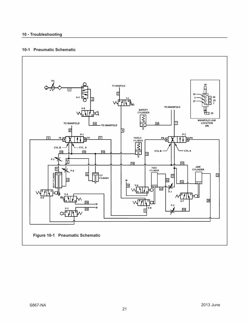
10 - Troubleshooting
Figure 10-1 Pneumatic Schematic
10-1 Pneumatic Schematic
2013 JuneS867-NA

22
Figure 10-2 Troubleshooting Valve Locations – S-867 Right Side View
Note: The complete pneumatic schematic is shown in the beginning of the Troubleshooting section, Figure 10-1.
10-2 Troubleshooting Guide (arranged in sequence of machine operation)
• To reduce the risk associated with sharp blade hazards:− Keep hands and fi ngers away from tape cutoff blades under orange blade guards. The blades are
extremely sharp • To reduce the risk associated with mechanical and pneumatic hazards:− Allow only properly trained and qualifi ed personnel to operate and/or service this equipment
• To reduce the risk associated with pinch and entanglement hazards:− Turn air supply off and disconnect before performing any adjustments, maintenance or servicing the
machine
10 - Troubleshooting (continued)
Problem Possible Cause Correction
Unit does not cycle.
Cut-off assembly does not retract.
Buffi ng assembly does not retract.
1. Air supply shut off or not connected to unit.
2. Cover open.3. Valve V-8 out of adjustment or
defective.4. Valve V-9 out of adjustment or
defective.5. Valve V-2 out of adjustment or
defective.6. Power valve P-1 defective.7. Kinked air lines.
1. Valve V-3 out of adjustment.2. Cut-off assembly jammed with
tape holding roller on tape feed assembly.
1. Valve V-3 out of adjustment or defective.
2. Flow control closed.
1. Check main air supply line and turn on unit.
2. Close cover.3. Adjust or replace valve V-8.
(see page 10)4. Adjust or replace valve V-9.
5. Adjust or replace valve V-2.
6. Replace valve.7. Straightened or replace air lines.
1. Adjust or replace valve V-3.2. Turn off air and retract cut-off
assembly. Actuate and hold V-3 valve and turn on air.
1. Adjust or replace valve V-3.2. Adjust retract fl ow control for
buff cylinder.
2013 JuneS867-NA
WARNING
Flow Controls

23
10 - Troubleshooting (continued)
10-2 Troubleshooting Guide (arranged in sequence of machine operation)
Possible Cause1. Valve V-4 out of adjustment or
defective.2. Flow control closed.
3. Power valve P-2 defective.
1. Valve V-3 out of adjustment or defective.
2. Valve V-2 out of adjustment or defective, sticks closed when box paddle is actuated.
1. Valve V-6 out of adjustment or defective.
2. Valve V-5 out of adjustment or defective.
3. Power valve P-2 defective.4. Valve V-7 out of adjustment or
defective.
1. Valve V-7 out of adjustment or defective.
2. Valve V-5 out of adjustment or defective.
3. Check for loose cylinder rod connection.
1. Dull blade.2. Blade out of adjustment.
1. Bad jaw roller.2. Valve V-6 actuates before tape is in
jaw assembly.3. Valve V-7 actuated before tape is
clamped.4. Wave washer missing from tape
holding roller5. Jaws close too slow.6. Feed cylinder extends too fast.7. Low clamping force on tape.
Missing or broken jaw spring 8. Bad one-way roller assembly. End of
tape is not fed into the jaw assembly.
ProblemCut-off assembly and buffi ng as-sembly cycle extend and retract and unit stops.
Buffi ng arm/cut-off blade out of sequence, oscillate back and forth.
Feed assembly retracts and stops.
Feed cylinder extends but does not actuate V-8 valve.
Tape not cutting or tape end shred-ding or buffi ng rollers stop in mid-stroke and do not apply the tape.
Tape not being held by jaw assembly.
Correction1. Adjust or replace valve V-4.
2. Adjust extend fl ow control for feed cylinder.
3. Replace valve.
1. Turn off air supply adjust valve V-3. Retract cut and buffi ng cylinder to retracted positions. Actuate and hold V-3 as air is turned on. This should put air circuitry in sequence.
2. Adjust or replace valve V-2.
1. Adjust or replace valve V-6.
2. Adjust or replace valve V-5.
3. Replace valve.4. Adjust or replace valve V-7.
1. Adjust or replace valve V-7.
2. Adjust or replace valve V-5.
3. Retighten and adjust V-8 valve if needed.
1. Replace blade.2. Readjust blade and tighten screw.
1. Replace roller.2. Adjust V-6 valve.
3. Adjust or replace V-7 valve.4. Replace wave washer.
5. Adjust jaw cylinder fl ow control.6. Adjust fl ow control for extending
feed cylinder.7. Replace jaw spring.8. Replace one-way roller assem-
bly located on feed assembly.
2013 JuneS867-NA
• To reduce the risk associated with sharp blade hazards:− Keep hands and fi ngers away from tape cutoff blades under orange blade guards. The blades are
extremely sharp • To reduce the risk associated with mechanical and pneumatic hazards:− Allow only properly trained and qualifi ed personnel to operate and/or service this equipment
• To reduce the risk associated with pinch and entanglement hazards:− Turn air supply off and disconnect before performing any adjustments, maintenance or servicing the
machine
WARNING

24
10 - Troubleshooting (continued)
Air LineNumber From / To Length1 Air Regulator / V-1 Valve 927mm [36.5 inch]2 V-1 Valve / V-9 Valve 457mm [18.0 inch]3 Manifold / V-2 Valve 483mm [19.0 inch]4 V-2 Valve / V-8 Valve 439mm [17.3 inch]5 V-8 Valve / P-1 Port PA 584mm [23.0 inch]6 V-3 Valve / P-1 Port PB 363mm [14.3 inch]7 Manifold / P-2 Port B 546mm [21.5 inch]8 P1 Port A / Cut Cyl. Rod 533mm [21.0 inch]9 P-1 Valve / F4 End Port 584mm [23.0 inch]10 Cut Cyl. Hd / Pad.Cyl.Rod 394mm [15.5 inch]11 F-3 End Port / Buff Cyl. Hd 229mm [9.0 inch]12 V-6 Valve / P-2 Port PB 216mm [8.5 inch]13 V-4 Valve/P-2 Port PA 241mm [9.5 inch]14 P-2 Port B / V-5 Valve 330mm [13.0 inch]15 P-2 Port B / V-7 Valve 541 mm [21.3 inch]
Air LineNumber From / To Length16 P-2 Port A / Jaw Cyl. Rod 361mm [14.3 inch]17 P-2 Port A / F1 End Port 488mm [19.2 inch]18 Manifold / V-6 Valve 635mm [25.0 inch]19 V7 Valve / F2 End Port 787mm [31.0 inch]20 P-1 Port A / F3 End Port 610mm [24.0 inch]21 F4 Side Port / Buff Cyl.Rod 279mm [11.0 inch]22 F2 Side Port / Feed Cyl.Hd. 622mm [24.50 inch]23 F1 Side Port / Feed Cyl.Rod 521mm [20.5 inch]24 Manifold / V-4 Valve 305mm [12.0 inch]25 Manifold / V-3 Valve 622mm [24.5 inch]26 V-5 Valve / Jaw Cyl. Head 673mm [26.5 inch]27 Manifold / P-1 Port IN 483mm [19.0 inch]28 Manifold / V-9 Valve 254mm [10.0 inch]29 Manifold / Safety Cylinder 279mm [11.0 inch]30 P-1 Port A / Cut Cyl. Head 635 mm [25.0 inch]
Figure 10-3 Air Line Connections / Tubing Length
2013 JuneS867-NA
Flow Controls
PaddleCylinder Feed
Cylinder
KnifeAssembly
BuffAssembly
SafetyCylinder
JawAssembly
Manifold
V-9
F-2
F-1
F-4
F-3
V-8
V-1
V-2
V-7
V-6
V-5
P-1
P-2
10.3 Air Line Connections / Tubing Length

25
THIS PAGE IS BLANK

26
11.1 Recommended Spare Parts
It is suggested that the following spare parts be ordered and kept on hand:
Qty. Part Number Description
2 70-8601-0078-6 Blade – Serrated 4 78-8046-8594-5 Roller – Buffi ng
11.2 How To Order Replacement Parts
1. See Figures 11-1 to 11-9, in "Replacement Parts" section, to determine individual part and reference number.
2. Refer to the "Replacement Parts -- Illustrations and Parts Lists" section in this manual for part number and description.
Note – The complete description has been included for standard fasteners and some commercially available components. This has been done to allow obtaining these standard parts locally, should the customer elect to do so.
3. Refer to fi rst page of this instruction manual "Replacement Parts and Service Information", for replacement parts ordering information.
Important – Not all the parts listed are normally stocked items. Some parts or assemblies shown are available only on a special order basis. Contact 3M/Tape Dispenser Parts to confi rm item availability.
11.3 Repair Service
Refer to the fi rst page of this instruction manual "Replacement Parts and Service Information" for information on repair service.
11 - Replacement Parts And Service Information
2013 JuneS867-NA

27
Frame Assemblies
2013 JuneS867-NA
S867
Figure 11-1 Main Frame, Nest, Covers
Figure 11-2 Tape Drum / Feed / Jaw
Figure 11-3 Tape Feed Assembly
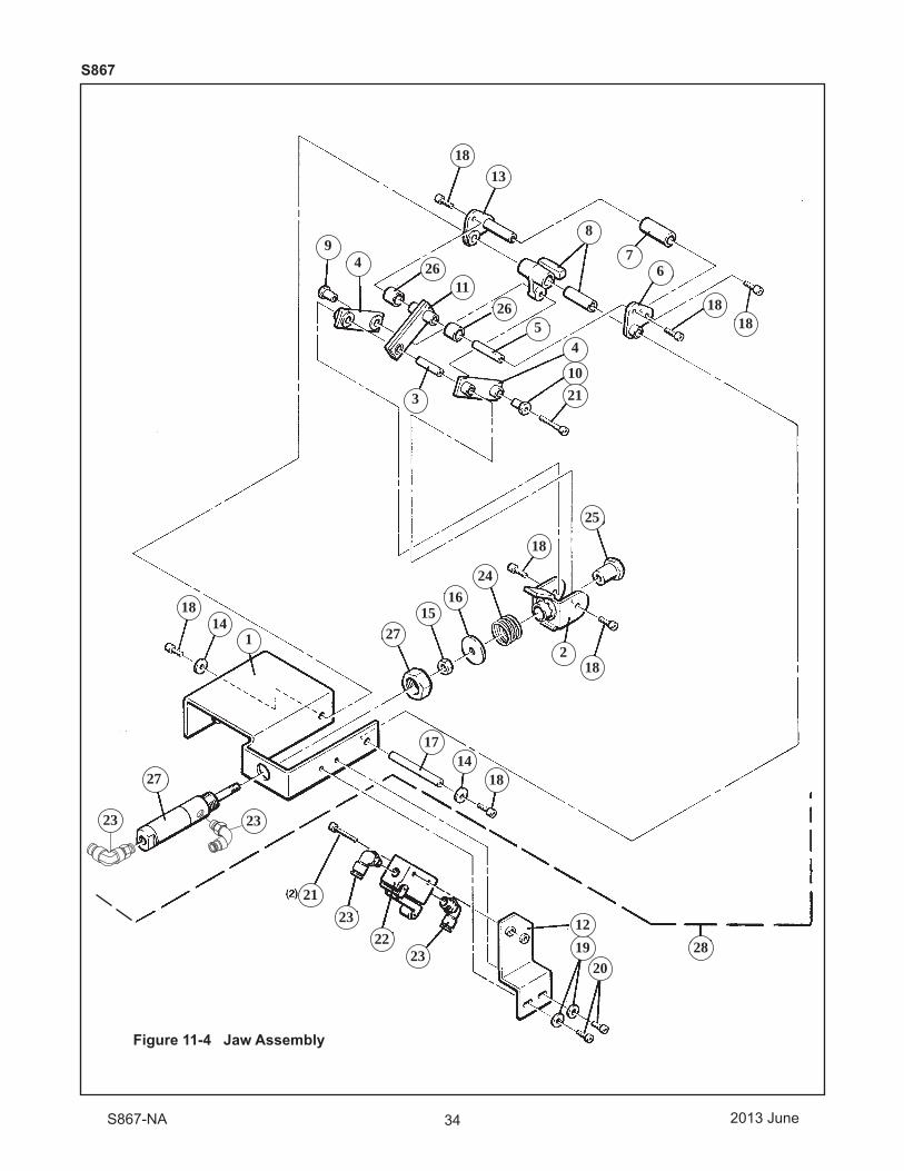
Figure 11-4 Jaw Assembly
Figure 11-5 Cut-Off Buffing Assembly
Figure 11-6 Cut-Off Assembly
Figure 11-7 Buffing Assembly
Figure 11-8 and 11-9 Pneumatic Components

28 2013 JuneS867-NA
S867
10
1919
29
14
14
23
33
12
12
21
31
16
1625
25
35
11
20
20 30
1524
34
13
32
17
26
18
28
27
1
5
5
3
3
3
3
7
22
6
6
4
4
8
9
9 Figure 11-1 Main Frame, Nest, Covers

29 2013 JuneS867-NA
S867
Figure 11-1
Ref. No. 3M Part No. Description
11-1-1 78-8133-9642-7 Frame Weldment11-1-2 78-8133-9649-2 Bumper11-1-3 70-8000-0878-4 Screw – Soc Hd, Hex Soc Dr, 10-24 x 3/8 Lg.11-1-4 78-8046-8599-4 Plate Assembly11-1-5 78-8046-8600-0 Plate – Shaft11-1-6 78-8161-4222-4 Bearing – Flanged, Oilite #FF-520-1011-1-7 78-8098-8978-1 Paddle Assembly11-1-8 78-8098-8975-7 Shaft – Paddle Stop11-1-9 78-8098-8974-0 Stop – Paddle UH11-1-10 78-8098-8976-5 Mandrel – Spring11-1-11 78-8098-8973-2 Spring – Torsion11-1-12 78-9260-8615-0 Pin – Slotted Spring, Med Duty, lJ8 Dia x 5/8 Lg11-1-13 26-1002-4389-3 Nut – Flanged, Spiralock, 1/4-2011-1-14 26-1006-1986-0 Screw – Soc Hd, Hex Soc Dr, 1/4-20 x 3/4 Lg.11-1-15 78-8133-9648-4 Label – Valve11-1-16 26-1006-1984-5 Screw – Flt Hd, Hex Soc Dr, Loc-Wel, 8-32 x 1/2 Lg.11-1-17 78-8059-5753-3 Shaft – Paddle11-1-18 78-8046-8510-1 Spring – Paddle11-1-19 78-8161-8389-7 Bearing – Nyliner, Thomson #4L1-FF11-1-20 78-8002-4778-1 Bearing – Nyliner, Thomson #4L2-FF11-1-21 78-8052-6250-4 Paddle – Box11-1-23 78-8098-9003-7 Nest Assembly11-1-24 78-8059-5756-6 Cover11-1-25 26-1006-2447-2 Nut – S-Lock, Nylon Insert, 8-3211-1-26 26-1006-2066-0 Latch – Over Center Draw, Southco #97-50-110-1511-1-27 78-8052-6257-9 Bracket – Mount, R/H11-1-28 78-8059-5746-7 Hinge – Cover11-1-29 70-8656-5934-9 Screw – Soc Hd, Hex Soc Dr, 8-32 x 1/4 Lg.11-1-30 78-8133-9643-5 Label – Flow Control11-1-31 78-8059-5741-8 Cover – Safety11-1-32 78-8133-9656-7 Label – Information11-1-33 78-8119-6594-2 Label – Warning, Sharp Knife/Rollers11-1-34 78-8119-6596-7 Label – Safety Instructions, Air Supply11-1-35 78-8119-6598-3 Label – Tape Threading

30
Figure 11-2 Tape Drum, Tape Feed, Jaw Assemblies
2013 JuneS867-NA
S867
10
10
1919
29
29
14
14
23
33
12
21
31
31
31
16
16
16
16
16
25
25
35
35
35
35
11
20
30
30
30
30
15
15
24
24
34
13
22
32
17
26
18
28
27
1
5
3
3
7
2
6
4
89
Tape Feed Tape Feed AssemblyAssembly
Jaw Jaw Assembly Assembly

31 2013 JuneS867-NA
S867
Figure 11-2
Ref. No. 3M Part No. Description
11-2-1 78-8046-8542-4 Shaft – Tape Arm11-2-2 78-8046-8511-9 Tape Arm Assembly (Pickup)11-2-3 78-8161-4227-3 Bearing – Flange, Oilite #FF-520-511-2-4 78-8052-6371-8 Shaft – Pickup11-2-5 78-8046-8545-7 Pickup Roller Assembly11-2-6 78-8059-5754-1 Bolt – Modifi ed11-2-7 78-8052-6334-6 Roller – Tension11-2-8 78-8046-8549-9 Plate – Tape Backup11-2-9 78-8023-2190-7 Drum – Tape11-2-10 78-8023-2191-5 Retainer – Tape11-2-11 78-8059-5772-3 Support – Tape Drum11-2-12 78-8046-8551-5 Shaft – Roller (Take-up)
11-2-13 78-8046-8562-2 Roller – Top Wrap11-2-14 78-8059-5781-4 Standoff – Wheel11-2-15 78-8059-5755-8 Standoff – Wheel (Eccentric)11-2-16 70-8656-5938-0 Screw – Soc Hd Hex Soc Dr, 1/4-20 x 1/2 Lg.11-2-17 70-8000-5377-2 Washer – Plain, Type A, 1/211-2-18 26-1006-1770-8 Screw – Soc Hd, Hex Soc Dr, 10-24 x 1 /2 Lg.11-2-19 78-8656-4003-7 Ring – Retaining E-Ring, Waldes #5133-3711-2-20 78-8656-5004-4 Ring – Retaining Grip Ring, Waldes #5555-2511-2-21 78-8014-1001-6 Bearing – Thrust, Oilite #TT-70611-2-22 26-1001-2646-0 Nut – Nyl Insert, 1/2-1311-2-23 70-8000-5374-9 Nut – Jam, 1 /2-1311-2-24 26-1000-0664-7 Washer – Shim, .50 ID x .75 OD x .015 Thk11-2-25 26-1002-4949-4 Screw – Self Tap, Thrd Form, Plastite #6-19 x 3/8 Lg.11-2-26 26-1006-1986-0 Screw – Soc Hd, Hex Soc Dr, 1/4-20 x 3/4 Lg.11-2-27 26-1002-8745-2 Washer – Plain, Type B, .28 ID x 1.0 OD x .06 Th11-2-28 78-8052-6390-8 Shaft – Tension11-2-29 26-1006-1981-1 Screw – Soc Hd, Hex Soc Dr, 1/4-20 x 1-1/4 Lg.11-2-30 26-1004-1508-7 Bushing – Adapter, Stationary, Dua-L-Vee, Bishop-Wisecarver#B-211-2-31 26-1002-6708-2 Washer – U-Bent, Assoc. Sp #U500-017011-2-32 26-1009-3643-9 Washer – Plain, 9/32 ID x 5/8 OD x 1/8 Thk11-2-33 70-8000-2641-4 Screw – Soc Hd, Hex Soc Dr, 1/4-20 x 5/8 Lg.11-2-34 78-8163-0100-2 Bearing – Thrust, Oilite #TT-50411-2-35 26-1004-1506-1 Wheel-Guide – Dua-L-Vee Bishop-Wisecarver#W2X

32
Figure 11-3 Tape Feed Assembly
= Full Assembly
2013 JuneS867-NA
10
19
14
23
12
21
16
16
16
16
11
1120
15
24
2217
1
5
3
7
2
6
6
4
8
9
S867
1325
18
26
27

33
2013 JuneS867-NA
S867
Figure 11-3
Ref. No. 3M Part No. Description
11-3-1 78-8052-6349-4 Plate – Stripper
11-3-2 78-8059-5758-2 Rail – Stripper
11-3-3 78-8052-6350-2 Bracket – Stripper Cylinder
11-3-4 78-8046-8559-8 Spacer – Stripper
11-3-5 78-8046-8560-6 Plate – Stripper (Tape)
11-3-7 78-8046-8562-2 Roller – Top Wrap
11-3-8 78-8046-8563-0 Roller – Wrap
11-3-9 78-8046-8564-8 Shaft – Roller (Clutch)
11-3-10 78-8059-5779-8 Roller Assembly – One-Way
11-3-11 78-8163-0109-3 Bearing – Thrust, Oilite #TT-703
11-3-12 78-8059-5778-0 Roller Assembly Kit – One-Way
(Includes Ref No. 29 and (2) Ref No. 30)
11-3-13 78-8046-8567-1 Shaft – Concave Roller
11-3-14 78-8046-8569-7 Cam – Hex
11-3-15 26-1004-6031-5 Screw – Soc Hd, Hex Soc Dr, 10-24 x 1/2 Lg.
11-3-16 78-8656-4003-7 Ring – Retaining E-Ring, Waldes #5133-37
11-3-17 26-1006-2403-5 Screw – Flt Hd, Hex Soc Dr, 10-24 x 1-1/2 Lg.
11-3-18 78-8656-5004-4 Ring - Retaining Grip Ring - Waldes #5555-25
11-3-19 70-7023-8090-1 Screw – Flt Hd, Hex Soc Dr, 1/4-20 x 1/2 Lg.
11-3-20 70-8000-1289-3 Screw – Flt Hd, Hex Soc Dr, 8-32 x 1/2 Lg.
11-3-21 78-8046-8570-5 Bumper – Cam
11-3-22 26-1002-2124-6 Screw – Flt Hd, Hex Soc Dr, 10-24 x 1/2 Lg.
11-3-23 26-1006-1333-5 Screw – Soc Hd, Hex Soc Dr, 10-24 x 3/8 Lg.
11-3-24 26-1004-5847-5 Nut – Nyl Insert, S-Lock, 10x24
11-3-25 26-1000-0922-9 Washer - Wave 1/4"
11-3-26 78-8068-3913-6 Roller - Concave
11-3-27 78-8111-1289-1 Full Assembly
34 2013 JuneS867-NA
10
19
14
14
23
23
12
21
21
16
25
11
20
15
24
13
22
17
26
26
18
18
1818
18
18
18
28
27
27
1
5
3
7
2
64
4
89
S867
Figure 11-4 Jaw Assembly
23 23

35 2013 JuneS867-NA
S867
Figure 11-4
Ref. No. 3M Part No. Description
11-4-1 78-8054-8685-5 Bracket – Jaw Mounting
11-4-2 78-8054-8687-1 Clevis – Air Cylinder
11-4-3 78-8054-8671-5 Shaft – Clevis
11-4-4 78-8054-8672-3 Jaw Link Assembly – Outer
11-4-5 78-8054-8673-1 Shaft – Link
11-4-6 78-8054-8680-6 Roller Plate Assembly – R/H
11-4-7 78-8054-8683-0 Roller – Jaws
11-4-8 78-8054-8684-8 Tape Clamp Assembly
11-4-9 78-8054-8674-9 Pin – Link Tap
11-4-10 78-8054-8675-6 Pin – Link Thru
11-4-11 78-8054-8676-4 Jaw – Link Assembly - Inner
11-4-12 78-8046-8541-6 Bracket – Valve
11-4-13 78-8079-5487-6 Roller Plate Assembly – L/H
11-4-14 12-7991-1737-4 Washer – Plain, Type A, #8
11-4-15 26-1004-0331-5 Nut – Jam, 5/16 - 24
11-4-16 26-1003-3708-3 Washer – Plain, .328 ID x 1.25 OD x .063 Thk
11-4-17 78-8054-8677-2 Shaft – Jaws
11-4-18 70-8000-0864-4 Screw – Soc Hd, Hex Soc Dr, 8-32 x 1/2 Lg.
11-4-19 26-1000-4442-4 Washer – Type A, #10
11-4-20 26-1006-1333-5 Screw – Soc Hd, Hex Soc Dr, 10-24 x 3/8 Lg.
11-4-21 70-8000-2155-5 Screw – Soc Hd, Hex Soc Dr, 8-32 x 1 Lg.
11-4-22 26-1000-0922-9 Washer - Wave 1/4"
11-4-23 26-1016-2163-4 Fitting - Elbow, 1/4 Tube x 1/4 NPT SMC Corp KQ2L07-35S
11-4-24 78-8054-8691-3 Spring – Jaw
11-4-25 78-8111-1279-2 Adapter – Air Cylinder
11-4-26 78-8054-8719-2 Spacer
11-4-27 26-1016-2151-9 Cylinder – Jaw, SMC Corp #NCMB106-0062C
11-4-28 78-8111-1282-6 Jaw Assembly (Replacement)

36
Figure 11-5 Cut-Off, Buffing Assemblies
2013 JuneS867-NA
S867
1
3
2
2
4
3
6
7
12 9
1014
11
8
13
Cut-Off Assembly (See Figure 11-6)
Buffing Assembly (See Figure 11-7)

37 2013 JuneS867-NA
S867
Figure 11-5
Ref. No. 3M Part No. Description
11-5-1 70-8000-0878-4 Screw – Soc Hd, Hex Soc Dr, 10-24 x 3/8 Lg
11-5-2 70-8656-5938-0 Screw – Soc Hd Hex Soc Dr, 1/4-20 x 1/2 Lg.
11-5-3 26-1006-1770-8 Screw – Soc Hd, Hex Soc Dr, 10-24 x 1 /2 Lg.
11-5-4 26-1007-3472-7 Washer – Plain, Hardened, 13/64 ID x 1/2 OD
11-5-6 26-1004-7415-9 Flow Control – Flairline #RFC-1/8 PK
11-5-7 26-1016-2159-2 Fitting – Male Connector, 1/4 O.D. Tube x 1/8 Male NPT, SMC Corp #KJH07-34S
11-5-8 78-8003-8731-4 Bushing – Snap, Heyco #2096
11-5-9 78-8133-9643-5 Label – Flow Control
11-5-10 26-1000-4442-4 Washer – Type A, #10
11-5-11 26-1016-2163-4 Fitting - Elbow, 1/4 Tube x 1/4 NPT SMC Corp KQ2L07-35S
11-5-12 26-1016-2160-0 Fitting - Elbow, 1/4 Tube x 1/8 NPT SMC Corp KJL07-34S
11-5-13 26-1016-2155-0 Filter/Regulator (Includes mounting bracket)
11-5-14 78-8119-6596-7 Label – Safety Instructions, Air Supply

38
Figure 11-6 Cut-Off Assembly
2013 JuneS867-NA
S867
10
12
12
11
13
13
15
7
2
6
4
8
9
(Includes Label)
3
14
1415
16

39 2013 JuneS867-NA
S867
Figure 11-6
Ref. No. 3M Part No. Description
11-6-1 78-8046-8572-1 Bracket – Air Cylinder
11-6-2 70-8601-0078-6 Blade
11-6-3 78-8046-8575-4 Blade Guard Assembly
11-6-4 78-8079-5480-1 Bracket – Blade Mounting
11-6-5 26-1000-8448-7 Nut – Jam, 1/4-28
11-6-6 12-7991-1735-8 Washer – Plain, Type A, #4
11-6-7 78-8068-3916-9 Clamp - Blade
11-6-8 78-8005-2959-2 Rivet – Pop, 1 /8 Dia, USM #AD-45-ABS
11-6-9 78-8046-8577-0 Bracket – Slide
11-6-10 78-8046-8578-8 Rod – Slide
11-6-11 70-8000-0864-4 Screw – Soc Hd, Hex Soc Dr, 8-32 x 1/2 Lg.
11-6-12 26-1006-1333-5 Screw – Soc Hd, Hex Soc Dr, 10-24 x 3/8 Lg.
11-6-13 26-1000-4442-4 Washer – Plain, Type A, #10
11-6-14 26-1016-2152-7 Cylinder – Cut, SMC Corp. #NCMB075-0200C
11-6-15 26-1016-2161-8 Fitting - Male Run Tee 1/4 Tube x 1/4 Tube x 1/8 Male NPT,
SMC Corp #KJY07-34S
11-6-16 26-1016-2160-0 Fitting - Elbow, 1/4 Tube x 1/8 NPT SMC Corp KJL07-34S

40
Figure 11-7 Buffing Assembly
2013 JuneS867-NA
S867
10
1019
19
23
23
12
21
21
16
16
25
25
11
11
20
20
20
20 24
24
22
22
17
17
26
26
18
18
18
1818
2827
1 5
3
7
7
2
2
6
6
4
8
8
9
9
14
1415
1513
18
14
1415
1513

41 2013 JuneS867-NA
S867
Figure 11-7
Ref. No. 3M Part No. Description
11-7-1 78-8052-6366-8 Plate – Arm Mounting
11-7-2 78-8059-5734-3 Rail – Buffi ng
11-7-3 78-8059-5735-0 Bracket – Mounting
11-7-4 78-8052-6369-2 Cam – Switch
11-7-5 78-8046-8585-3 Bracket – Cylinder
11-7-6 78-8046-8586-1 Shaft – Buffi ng Arm
11-7-7 78-8046-8587-9 Buffi ng Arm Assembly
11-7-8 78-8032-1206-3 Bearing – Flanged, Oilite #FF-636-3
11-7-9 78-8046-8588-7 Arm– Buffi ng
11-7-10 78-8046-8589-5 Mandrel – Spring
11-7-11 78-8046-8590-3 Spring – Buffi ng Roller
11-7-12 78-8046-8591-1 Plate – Buff Mounting
11-7-13 78-8046-8592-9 Sleeve – Buffi ng Roller
11-7-14 78-8046-8593-7 Spacer – Buffi ng Roller
11-7-15 78-8046-8594-5 Roller – Buffi ng
11-7-16 78-8046-8595-2 Shaft – Buffi ng
11-7-17 78-8656-4012-8 Ring – Retaining E-Ring, Waldes #5133-50
11-7-18 26-1006-1770-8 Screw – Soc Hd, Hex Soc Dr, 10-24 x 1/2 Lg.
11-7-19 70-8656-5938-0 Screw – Soc Hd, Hex Soc Dr, 1/4-20 x 1/2 Lg.
11-7-20 18-1755-2103-0 Nut – Nylon Insert, 10-24
11-7-21 26-1002-4389-3 Nut –- Flanged, Spiralock, 1/4-20
11-7-22 78-8052-6367-6 Spacer – Roller
11-7-23 70-8000-1495-6 Screw – Soc Hd, Hex Soc Dr, 1/4-20 x 1-1/2 Lg.
11-7-24 26-1004-1506-1 Wheel – Guide, Dua-L-Vee #W2X
11-7-25 26-1004-1508-7 Bushing – Adapter, Stationary, Dua-L-Vee #B-2
11-7-26 26-1006-1771-6 Washer – Plain, SST, H.K. Metalcraft, #18-8
11-7-27 78-8059-5763-2 Brace – Buffi ng Assembly
11-7-28 70-8000-0878-4 Screw – Soc Hd, Hex Soc Dr, 10-24 x 3/8 Lg.

42
Figure 11-8 Pneumatic Components
2013 JuneS867-NA
S867
10
10
17
19
19
19
12
12
21
11
18
22
22
22
22
22
22
22
22
22
1414
20
13
13
13
15
17
16
1
5
3
7
2
6
4
8
9

43
S867
Figure 11-8
Ref. No. 3M Part No. Description
11-8-1 78-8046-8553-1 Mount – Cylinder Rod
11-8-2 78-8046-8572-1 Bracket – Air Cylinder
11-8-3 78-8052-6341-1 Mount – Valve V-5
11-8-4 78-8046-8597-8 Bracket – Switch
11-8-5 70-8656-5938-0 Screw – Soc Hd Hex Soc Dr, 1/4-20 x 1/2 Lg.
11-8-6 26-1006-1770-8 Screw – Soc Hd, Hex Soc Dr, 10-24 x 1 /2 Lg.
11-8-7 26-1007-3472-7 Washer – Plain, Hardened, 13/64 ID x 1/2 OD
11-8-8 26-1000-8448-7 Nut – Jam, 1/4-28
11-8-9 26-1002-8745-2 Washer – Plain, Type B, .28 ID x 1.0 OD x .06 Th
11-8-10 26-1004-7411-8 Valve – Air, Internal Check Valve, One-Way Roller
1/8 NPT Ports, SMC #NVM-131-NO1-02-X6
11-8-11 70-8000-2155-5 Screw – Soc Hd, Hex Soc Dr, 8-32 x 1 Lg.
11-8-12 26-1004-7410-0 Valve – Air, 3-Way, Roller Actuator, SMC #VM 131 -N01 -01
11-8-13 26-1006-1985-2 Screw — Soc Hd, Hex Soc Dr, 8-32 x 1-1/4 Lg.
11-8-14 26-1016-2159-2 Fitting – Male Connector, 1/4 O.D. Tube x 1/8 Male NPT, SMC Corp #KJH07-34S
11-8-15 78-8079-5483-5 Spacer – Valve, V-4
11-8-16 26-1002-6708-2 Washer – U-Bent, Assoc. Sp #U500-0170
11-8-17 78-8003-8731-4 Bushing – Snap, Heyco #2096
11-8-18 70-8000-2641-4 Screw – Soc Hd, Hex Soc Dr, 1/4-20 x 5/8 Lg.
11-8-19 26-1005-5133-7 Nut Plate – Ohio #TP1416
11-8-20 26-1005-5410-9 Valve – 3-Way, Brass Ball, Manual Actuator,
1/8 NPTF, SMC #701-2F2F2F-BT
11-8-21 26-1016-2147-7 Cylinder – Buffi ng, SMC Corp #NCMB075-0512C
11-8-22 26-1016-2160-0 Fitting - Elbow, 1/4 Tube x 1/8 NPT SMC Corp KJL07-34S
2013 JuneS867-NA

44 2013 JuneS867-NA
10
40
10
19
23
33
33
33
33
33
38
38
33
33
33
23
23
12
12
21
21
21
31
3231
16
25
25
25
20
36
36
34
15
24
14
13
22
26
16
16
26
18
28
1
5
3
7
4
8
8
9
9
2927
37
1128
6
17
S867
Figure 11-9 Pneumatic Components
39
41
30
35
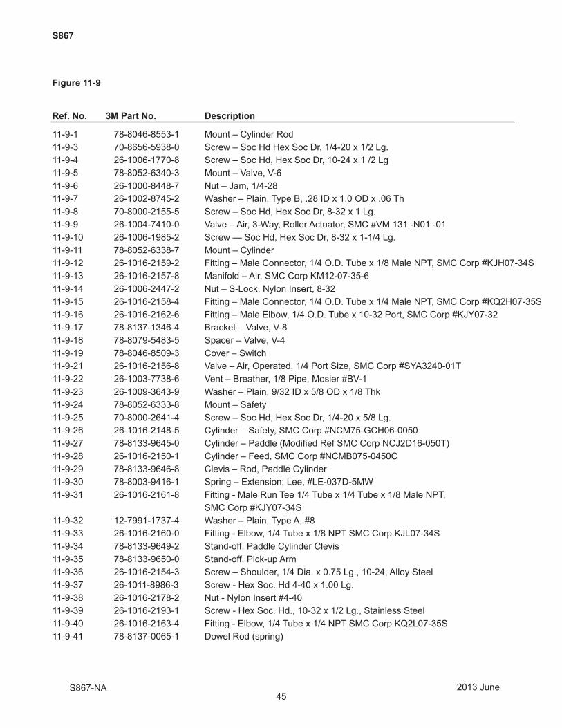
45
S867
Figure 11-9
Ref. No. 3M Part No. Description
11-9-1 78-8046-8553-1 Mount – Cylinder Rod 11-9-3 70-8656-5938-0 Screw – Soc Hd Hex Soc Dr, 1/4-20 x 1/2 Lg.11-9-4 26-1006-1770-8 Screw – Soc Hd, Hex Soc Dr, 10-24 x 1 /2 Lg11-9-5 78-8052-6340-3 Mount – Valve, V-611-9-6 26-1000-8448-7 Nut – Jam, 1/4-2811-9-7 26-1002-8745-2 Washer – Plain, Type B, .28 ID x 1.0 OD x .06 Th11-9-8 70-8000-2155-5 Screw – Soc Hd, Hex Soc Dr, 8-32 x 1 Lg.11-9-9 26-1004-7410-0 Valve – Air, 3-Way, Roller Actuator, SMC #VM 131 -N01 -0111-9-10 26-1006-1985-2 Screw — Soc Hd, Hex Soc Dr, 8-32 x 1-1/4 Lg.11-9-11 78-8052-6338-7 Mount – Cylinder11-9-12 26-1016-2159-2 Fitting – Male Connector, 1/4 O.D. Tube x 1/8 Male NPT, SMC Corp #KJH07-34S11-9-13 26-1016-2157-8 Manifold – Air, SMC Corp KM12-07-35-611-9-14 26-1006-2447-2 Nut – S-Lock, Nylon Insert, 8-3211-9-15 26-1016-2158-4 Fitting – Male Connector, 1/4 O.D. Tube x 1/4 Male NPT, SMC Corp #KQ2H07-35S11-9-16 26-1016-2162-6 Fitting – Male Elbow, 1/4 O.D. Tube x 10-32 Port, SMC Corp #KJY07-3211-9-17 78-8137-1346-4 Bracket – Valve, V-811-9-18 78-8079-5483-5 Spacer – Valve, V-411-9-19 78-8046-8509-3 Cover – Switch11-9-21 26-1016-2156-8 Valve – Air, Operated, 1/4 Port Size, SMC Corp #SYA3240-01T11-9-22 26-1003-7738-6 Vent – Breather, 1/8 Pipe, Mosier #BV-111-9-23 26-1009-3643-9 Washer – Plain, 9/32 ID x 5/8 OD x 1/8 Thk11-9-24 78-8052-6333-8 Mount – Safety11-9-25 70-8000-2641-4 Screw – Soc Hd, Hex Soc Dr, 1/4-20 x 5/8 Lg.11-9-26 26-1016-2148-5 Cylinder – Safety, SMC Corp #NCM75-GCH06-005011-9-27 78-8133-9645-0 Cylinder – Paddle (Modifi ed Ref SMC Corp NCJ2D16-050T)11-9-28 26-1016-2150-1 Cylinder – Feed, SMC Corp #NCMB075-0450C11-9-29 78-8133-9646-8 Clevis – Rod, Paddle Cylinder11-9-30 78-8003-9416-1 Spring – Extension; Lee, #LE-037D-5MW11-9-31 26-1016-2161-8 Fitting - Male Run Tee 1/4 Tube x 1/4 Tube x 1/8 Male NPT, SMC Corp #KJY07-34S11-9-32 12-7991-1737-4 Washer – Plain, Type A, #811-9-33 26-1016-2160-0 Fitting - Elbow, 1/4 Tube x 1/8 NPT SMC Corp KJL07-34S11-9-34 78-8133-9649-2 Stand-off, Paddle Cylinder Clevis11-9-35 78-8133-9650-0 Stand-off, Pick-up Arm11-9-36 26-1016-2154-3 Screw – Shoulder, 1/4 Dia. x 0.75 Lg., 10-24, Alloy Steel11-9-37 26-1011-8986-3 Screw - Hex Soc. Hd 4-40 x 1.00 Lg.11-9-38 26-1016-2178-2 Nut - Nylon Insert #4-4011-9-39 26-1016-2193-1 Screw - Hex Soc. Hd., 10-32 x 1/2 Lg., Stainless Steel11-9-40 26-1016-2163-4 Fitting - Elbow, 1/4 Tube x 1/4 NPT SMC Corp KQ2L07-35S11-9-41 78-8137-0065-1 Dowel Rod (spring)
2013 JuneS867-NA

46
THIS PAGE IS BLANK


