1 / 18
87045 LIMOGES Cedex Telephone: +33 5 55 06 87 87 – FAX: +33 5 55 06 88 88
DXDXDXDX3333 MCB 25kA 80A to 125A MCB 25kA 80A to 125A MCB 25kA 80A to 125A MCB 25kA 80A to 125A (1,5 modules per p(1,5 modules per p(1,5 modules per p(1,5 modules per poooole)le)le)le)
Cat N°(s): Cat N°(s): Cat N°(s): Cat N°(s): 4 097 49 to 51, 4 097 62 to 64, 4 097 75 to 77, 4 097 49 to 51, 4 097 62 to 64, 4 097 75 to 77, 4 097 49 to 51, 4 097 62 to 64, 4 097 75 to 77, 4 097 49 to 51, 4 097 62 to 64, 4 097 75 to 77, 4 097 88 to 90, 4 098 01 to 03, 4 098 14 to 16, 44 097 88 to 90, 4 098 01 to 03, 4 098 14 to 16, 44 097 88 to 90, 4 098 01 to 03, 4 098 14 to 16, 44 097 88 to 90, 4 098 01 to 03, 4 098 14 to 16, 4 098098098098 40 to 40 to 40 to 40 to 42, 442, 442, 442, 4 098 53 to 55 098 53 to 55 098 53 to 55 098 53 to 55
CONTENTSCONTENTSCONTENTSCONTENTS PAGES
1. Description - Use ................................ 1 2. Range................................................. 1 3. Overall dimensions ............................. 1 4. Preparation - Connection .................... 1 5. General characteristics ....................... 2 6. Conformities and approvals ................ 7 7. Characteristic curves .......................... 7 8. Auxiliaries and accessories............... 16
1. DESCRIPTION 1. DESCRIPTION 1. DESCRIPTION 1. DESCRIPTION ---- USEUSEUSEUSE
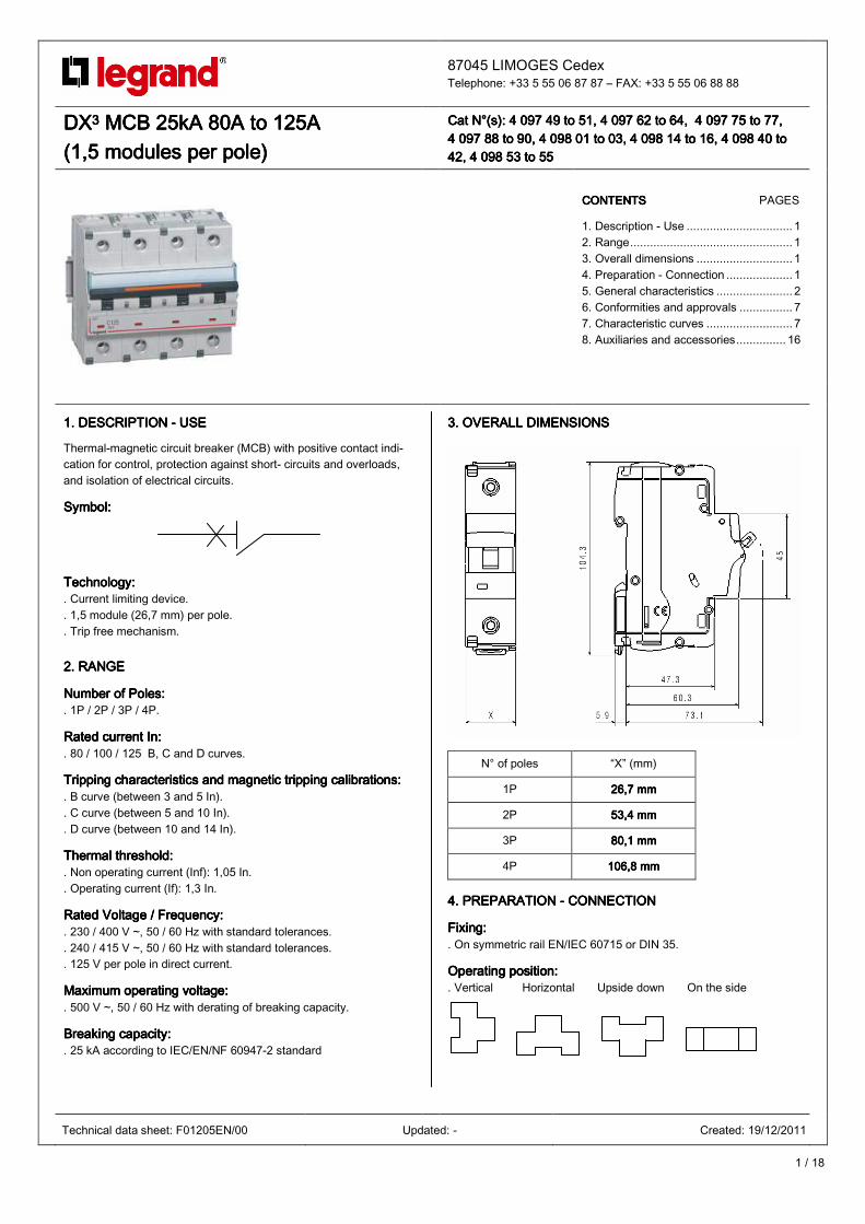
Thermal-magnetic circuit breaker (MCB) with positive contact indi-cation for control, protection against short- circuits and overloads, and isolation of electrical circuits.
SymbolSymbolSymbolSymbol::::
TechnoloTechnoloTechnoloTechnologygygygy:::: . Current limiting device. . 1,5 module (26,7 mm) per pole. . Trip free mechanism.
2. 2. 2. 2. RANGERANGERANGERANGE
Number of Poles:Number of Poles:Number of Poles:Number of Poles: . 1P / 2P / 3P / 4P.
Rated current InRated current InRated current InRated current In:::: . 80 / 100 / 125 B, C and D curves.
Tripping characteristics and magnetic tripping calibrationsTripping characteristics and magnetic tripping calibrationsTripping characteristics and magnetic tripping calibrationsTripping characteristics and magnetic tripping calibrations:::: . B curve (between 3 and 5 In). . C curve (between 5 and 10 In). . D curve (between 10 and 14 In).
Thermal threshold:Thermal threshold:Thermal threshold:Thermal threshold: . Non operating current (Inf): 1,05 In. . Operating current (If): 1,3 In.
Rated Voltage / Frequency:Rated Voltage / Frequency:Rated Voltage / Frequency:Rated Voltage / Frequency: . 230 / 400 V ~, 50 / 60 Hz with standard tolerances. . 240 / 415 V ~, 50 / 60 Hz with standard tolerances. . 125 V per pole in direct current.
Maximum operating voltage:Maximum operating voltage:Maximum operating voltage:Maximum operating voltage: . 500 V ~, 50 / 60 Hz with derating of breaking capacity.
Breaking capacity:Breaking capacity:Breaking capacity:Breaking capacity: . 25 kA according to IEC/EN/NF 60947-2 standard
3. 3. 3. 3. OVERALL DIMENSIONSOVERALL DIMENSIONSOVERALL DIMENSIONSOVERALL DIMENSIONS
4. 4. 4. 4. PREPARATION PREPARATION PREPARATION PREPARATION ---- CONNECTION CONNECTION CONNECTION CONNECTION
Fixing:Fixing:Fixing:Fixing: . On symmetric rail EN/IEC 60715 or DIN 35.
Operating position:Operating position:Operating position:Operating position: . Vertical Horizontal Upside down On the side
N° of poles “X” (mm)
1P 22226666,7 mm,7 mm,7 mm,7 mm
2P 53,4 mm53,4 mm53,4 mm53,4 mm
3P 80,1 mm80,1 mm80,1 mm80,1 mm
4P 106,106,106,106,8888 mm mm mm mm
Technical data sheet: F01205EN/00 Updated: - Created: 19/12/2011

2 / 18
DXDXDXDX3333 MCB 25kA 80A to 125A MCB 25kA 80A to 125A MCB 25kA 80A to 125A MCB 25kA 80A to 125A (1,5 modules per p(1,5 modules per p(1,5 modules per p(1,5 modules per poooole)le)le)le)
Cat N°(s): Cat N°(s): Cat N°(s): Cat N°(s): 4 097 49 to 51, 4 097 62 to 64, 4 097 75 to 77, 4 097 49 to 51, 4 097 62 to 64, 4 097 75 to 77, 4 097 49 to 51, 4 097 62 to 64, 4 097 75 to 77, 4 097 49 to 51, 4 097 62 to 64, 4 097 75 to 77, 4 097 88 to 90, 4 098 01 to 03, 4 098 14 to 16, 44 097 88 to 90, 4 098 01 to 03, 4 098 14 to 16, 44 097 88 to 90, 4 098 01 to 03, 4 098 14 to 16, 44 097 88 to 90, 4 098 01 to 03, 4 098 14 to 16, 4 098098098098 40 to 40 to 40 to 40 to 42, 4 098 53 to 5542, 4 098 53 to 5542, 4 098 53 to 5542, 4 098 53 to 55
4. PREPARATION 4. PREPARATION 4. PREPARATION 4. PREPARATION –––– CONNECTION CONNECTION CONNECTION CONNECTION (continued)
Supply:Supply:Supply:Supply: . Either from the top or the bottom
Terminal depth:Terminal depth:Terminal depth:Terminal depth: . 19 mm. . It is possible to separate the terminals by retractable insulation shields.
Stripping length recommended:Stripping length recommended:Stripping length recommended:Stripping length recommended: . 17 mm for main terminals. . 10 mm for automatic terminals.
Screw head:Screw head:Screw head:Screw head: . Allen screw.
Tightening torque:Tightening torque:Tightening torque:Tightening torque: . Recommended: 5.5 Nm. . Mini 4.5 Nm . Maxi 6 Nm.
Tools required:Tools required:Tools required:Tools required: . For terminals: Allen wrench 4 mm. . For fixing: flat screwdriver 5,5 mm (6 mm maximum).
Connectable section:Connectable section:Connectable section:Connectable section: . For main terminals:
Copper cable
Without ferrule Without ferrule
Rigid cable 6 mm² 6 mm² 6 mm² 6 mm² to 70 to 70 to 70 to 70 mm²mm²mm²mm² ----
Flexible cable 6 mm² 6 mm² 6 mm² 6 mm² to 50 to 50 to 50 to 50 mm²mm²mm²mm² 6 mm² 6 mm² 6 mm² 6 mm² totototo 50 mm² 50 mm² 50 mm² 50 mm²
. For automatic terminals:
Copper cable
Without ferrule Without ferrule
Rigid cable 0.75 mm² 0.75 mm² 0.75 mm² 0.75 mm² to 2.5 to 2.5 to 2.5 to 2.5 mm²mm²mm²mm² ----
Flexible cable 0.75 mm² 0.75 mm² 0.75 mm² 0.75 mm² to 2.5 to 2.5 to 2.5 to 2.5 mm²mm²mm²mm² 0.75 mm² 0.75 mm² 0.75 mm² 0.75 mm² to 1.5 to 1.5 to 1.5 to 1.5 mm²mm²mm²mm²
Manual actuation of the Manual actuation of the Manual actuation of the Manual actuation of the MCBMCBMCBMCB:::: . Ergonomic 2 position handle:
0 / OFF: Device open. I / ON: Device closed.
4. PREPARATION 4. PREPARATION 4. PREPARATION 4. PREPARATION –––– CONNECTION CONNECTION CONNECTION CONNECTION (continued)
ContacContacContacContact status displayt status displayt status displayt status display:::: . By marking of the associated m.c.b. handle:
“O-Off“ white on a green background = contacts opened. “I-On” white on a red background = contacts closed.
. By mechanical indicator on front face: Green = contacts opened. Red = contacts closed.
Sealing:Sealing:Sealing:Sealing: . Possible in ʺOpenʺ position (OFF) or ʺCloseʺ position (ON).
Lockout::Lockout::Lockout::Lockout:: . By 5 mm padlock (cat. n° 4 06313) or 6 mm padlock (cat. n° 0 227 97) with padlock support (cat. n° 4 063 03) in “Open” position
Consignment:Consignment:Consignment:Consignment: . On site padlocking system, possible only open circuit - 0 / OFF handle position - with 1,5mm² stripped wire for example or 2,4mm wide Colring.
Labelling:Labelling:Labelling:Labelling: . Circuit identification by way of a label inserted in the label holder situated on the product.
5. GENERAL CHARACTERISTICS5. GENERAL CHARACTERISTICS5. GENERAL CHARACTERISTICS5. GENERAL CHARACTERISTICS
FroFroFroFront side marking:nt side marking:nt side marking:nt side marking: . By permanent ink pad printing showing:
-Trade name: DX3 - Breaking curve - Rated current (in A) - Icu in kA, Breaking capacity according to IEC/ EN 60947-2 standard (25kA) - Catalogue number and logo - Mark: Legrand
Technical data sheet: F01205EN/00 Updated: - Created: 19/12/2011

3 / 18
DXDXDXDX3333 MCB 25kA 80A to 125A MCB 25kA 80A to 125A MCB 25kA 80A to 125A MCB 25kA 80A to 125A (1,5 modules per p(1,5 modules per p(1,5 modules per p(1,5 modules per poooole)le)le)le)
Cat N°(s): Cat N°(s): Cat N°(s): Cat N°(s): 4 097 49 to 51, 4 097 62 to 64, 4 097 75 to 77, 4 097 49 to 51, 4 097 62 to 64, 4 097 75 to 77, 4 097 49 to 51, 4 097 62 to 64, 4 097 75 to 77, 4 097 49 to 51, 4 097 62 to 64, 4 097 75 to 77, 4 097 88 to 90, 4 098 01 to 03, 4 098 14 to 16, 44 097 88 to 90, 4 098 01 to 03, 4 098 14 to 16, 44 097 88 to 90, 4 098 01 to 03, 4 098 14 to 16, 44 097 88 to 90, 4 098 01 to 03, 4 098 14 to 16, 4 098098098098 40 to 40 to 40 to 40 to 42, 4 098 53 to 5542, 4 098 53 to 5542, 4 098 53 to 5542, 4 098 53 to 55
5. GE5. GE5. GE5. GENERAL CHARACTERISTICSNERAL CHARACTERISTICSNERAL CHARACTERISTICSNERAL CHARACTERISTICS (continued)
ShortShortShortShort----circuit breaking circuit breaking circuit breaking circuit breaking capacity:capacity:capacity:capacity: . Alternate current 50/60Hz, single-phase or three-phase network, according to IEC 60947-2. B, C and D curves
Un 1P 2P 3P / 4P
110 V~ 36 kA36 kA36 kA36 kA 72 kA72 kA72 kA72 kA ----
230 V~ 25 kA25 kA25 kA25 kA 50 kA50 kA50 kA50 kA 50 kA50 kA50 kA50 kA
400 V~ -------- 25 kA25 kA25 kA25 kA 25 kA25 kA25 kA25 kA
440 V~ ---- 20kA20kA20kA20kA 20kA20kA20kA20kA
500 V~
IcuIcuIcuIcu
---- 10kA10kA10kA10kA 10kA10kA10kA10kA
110 V~
230 V~
400 V~
IcsIcsIcsIcs 75% of Icu75% of Icu75% of Icu75% of Icu 75% of Icu75% of Icu75% of Icu75% of Icu 75% of Icu75% of Icu75% of Icu75% of Icu
ShortShortShortShort----circuit bcircuit bcircuit bcircuit breaking capacity of reaking capacity of reaking capacity of reaking capacity of only one only one only one only one pole:pole:pole:pole: . Three-phase network 220 / 380 V~ to 240 / 415 V~
- for TN neutral system, Icn1 = 25 kA (under 220 to 240 V~) - for IT neutral system, Iit = 6,25 kA (under 380 to 415 V~)
. In three-phase network 110 / 220 V~ to 120 / 240 V~ - for TN neutral system, Icn1 = 50 kA (under 110 to 127 V~) - for IT neutral system, Iit = 12,5 kA (under 220 to 240 V~)
ShortShortShortShort----circuit bcircuit bcircuit bcircuit breaking capacity in DC current:reaking capacity in DC current:reaking capacity in DC current:reaking capacity in DC current: . Direct current according to standard IEC 60947-2
Un 1P 2P 3P 4P
24 ÷ 48 V d.c. 25252525 kA kA kA kA 25252525 kA kA kA kA ---- ----
110 V d.c. ---- 25252525 kA kA kA kA 25252525 kA kA kA kA ----
230 V d.c.
IcuIcuIcuIcu
---- ---- ---- 25252525 kA kA kA kA
24 ÷ 48 V d.c. 25252525 kA kA kA kA 22225555 kA kA kA kA ---- ----
110 V d.c. ---- 25252525 kA kA kA kA 25252525 kA kA kA kA ----
230 V d.c.
IcsIcsIcsIcs
---- ---- ---- 25252525 kA kA kA kA
Minimum operating voltage Minimum operating voltage Minimum operating voltage Minimum operating voltage :::: . 12 V a.c. / d.c. per pole.
Pulse rated voltage:Pulse rated voltage:Pulse rated voltage:Pulse rated voltage: . Uimp = 6 kV (wave 1.5 / 50 µs).
Insulation rated voltage:Insulation rated voltage:Insulation rated voltage:Insulation rated voltage: . Ui = 500 V.
5. GENERAL CHARACTERISTICS5. GENERAL CHARACTERISTICS5. GENERAL CHARACTERISTICS5. GENERAL CHARACTERISTICS (continued)
Pollution degree::Pollution degree::Pollution degree::Pollution degree:: . 3.
Dielectric strength:Dielectric strength:Dielectric strength:Dielectric strength: . 2500 V.
Operation at 400Hz:Operation at 400Hz:Operation at 400Hz:Operation at 400Hz: . The magnetic thresholds increase by 45%.
Load to cLoad to cLoad to cLoad to closlosloslose and open of a pole trough the handlee and open of a pole trough the handlee and open of a pole trough the handlee and open of a pole trough the handle:::: . 0,17 Nm per pole to close. . 0,09 Nm per pole to open.
Mechanical endurance according to IEC 60947Mechanical endurance according to IEC 60947Mechanical endurance according to IEC 60947Mechanical endurance according to IEC 60947----2 :2 :2 :2 : . 20 000 operations without load . 10 000 operations with load (under In x Cos ϕ=0.9) . 2 000 operations with load (under In in DC current)
Enclosure mEnclosure mEnclosure mEnclosure material:aterial:aterial:aterial: . Polyester. . Characteristics of this material: self extinguishing, heat and fire resistant according to EN 60898-1, glow-wire test at 960°C for external parts made of insulating material necessary to retain in position current-carrying parts and parts of protective circuit (650°C for all other external parts made of insulating material).
Average weight per pole:Average weight per pole:Average weight per pole:Average weight per pole: . 0,220 kg.
Volume when packed:Volume when packed:Volume when packed:Volume when packed:
Volume (dm³ )
Single pole 0,360,360,360,36
Double pole 0,630,630,630,63
Triple / Four pole 1,141,141,141,14
Ambient operating temperatAmbient operating temperatAmbient operating temperatAmbient operating temperature:ure:ure:ure: . Min. = -25°C. Max. = +70°C
Ambient storage temperature:Ambient storage temperature:Ambient storage temperature:Ambient storage temperature:
. Min. = -40°C. Max. = +70°C
Protection class:Protection class:Protection class:Protection class: . Protection index of terminals against solid and liquid bodies:
IP 20 (according to IEC 529, EN 60529 et NF C 20-010). . Protection index of the box against solid and liquid bodies:
IP 40 (according to IEC 529, EN 60529 et NF C 20-010). . Protection index against mechanical shocks: IK 02 (according to EN 50102 et NF C 20-015).
Resistance to sinusoidal vibrations:Resistance to sinusoidal vibrations:Resistance to sinusoidal vibrations:Resistance to sinusoidal vibrations: . According to IEC 60068-2-35. . Axis : x, y, z. . Frequency range: 5÷100 Hz ; duration 90 minutes . Displacement (5÷13,2 Hz) : 1mm. . Acceleration (13,2÷100 Hz) : 0,7g (g=9,81 m/s2)
Technical data sheet: F01205EN/00 Updated: - Created: 19/12/2011

4 / 18
DXDXDXDX3333 MCB 25kA 80A to 125A MCB 25kA 80A to 125A MCB 25kA 80A to 125A MCB 25kA 80A to 125A (1,5(1,5(1,5(1,5 modules per p modules per p modules per p modules per poooole)le)le)le)
Cat N°(s): Cat N°(s): Cat N°(s): Cat N°(s): 4 097 49 to 51, 4 097 62 to 64, 4 097 75 to 77, 4 097 49 to 51, 4 097 62 to 64, 4 097 75 to 77, 4 097 49 to 51, 4 097 62 to 64, 4 097 75 to 77, 4 097 49 to 51, 4 097 62 to 64, 4 097 75 to 77, 4 097 88 to 90, 4 098 01 to 03, 4 098 14 to 16, 44 097 88 to 90, 4 098 01 to 03, 4 098 14 to 16, 44 097 88 to 90, 4 098 01 to 03, 4 098 14 to 16, 44 097 88 to 90, 4 098 01 to 03, 4 098 14 to 16, 4 098098098098 40 to 40 to 40 to 40 to 42, 4 098 53 to 5542, 4 098 53 to 5542, 4 098 53 to 5542, 4 098 53 to 55
5. GENERAL CHARACTERISTICS5. GENERAL CHARACTERISTICS5. GENERAL CHARACTERISTICS5. GENERAL CHARACTERISTICS (continued)
RecognitionRecognitionRecognitionRecognition:::: . Recognition of the circuit by insertion of a label in the label holder.
Power dissipated per Power dissipated per Power dissipated per Power dissipated per polepolepolepole at In (in W) : at In (in W) : at In (in W) : at In (in W) : . mcbs B, C and D curves
In 80 A 100 A 125 A
1P to 4P 8,88,88,88,8 10101010 15.615.615.615.6
. Impedance per pole (Ω) = Power dissipated In2
Derating of circuitDerating of circuitDerating of circuitDerating of circuit----breakers according to ambient temperaturebreakers according to ambient temperaturebreakers according to ambient temperaturebreakers according to ambient temperature :::: . The nominal characteristics of a circuit breaker are modified according to the ambient temperature inside the cabinet or the enclosure where the circuit breaker is located.
. Reference temperature: 40°C according IEC/EN 60947-2.
Ambient temperature / In
In (A) -25°C -10°C 0°C 10°C 20°C 30°C 40°C40°C40°C40°C 50°C 60°C 70°C
80 102102102102 97979797 94949494 91919191 88888888 84848484 80808080 76767676 72727272 69696969
100 128128128128 122122122122 118118118118 114114114114 110110110110 105105105105 100100100100 95959595 90909090 86868686
125 160160160160 152152152152 147147147147 142142142142 137137137137 131131131131 125125125125 119119119119 113113113113 108108108108
Derating of MCB for use with fluorescent lights:Derating of MCB for use with fluorescent lights:Derating of MCB for use with fluorescent lights:Derating of MCB for use with fluorescent lights: Ferromagnetic and electronic ballasts have a high inrush current for a short time. These currents can cause the tripping of circuit breakers. At the time of the installation, it should take into account the maximum number of ballasts per circuit breaker that the manufacturers of lamps and ballasts indicate in their catalogues.
Influence of the altitude:Influence of the altitude:Influence of the altitude:Influence of the altitude:
≤2000 m 3000 m 4000 m 5000 m
Dielectric holding 3000 V3000 V3000 V3000 V 2500250025002500 V V V V 2000 V2000 V2000 V2000 V 1500 V1500 V1500 V1500 V
Max operational Voltage 400 V400 V400 V400 V 400 V400 V400 V400 V 400 V400 V400 V400 V 400 V400 V400 V400 V
Derating at 40°C nonenonenonenone nonenonenonenone nonenonenonenone nonenonenonenone
Derating of Derating of Derating of Derating of MCBMCBMCBMCBs function of the number of devices side by side:s function of the number of devices side by side:s function of the number of devices side by side:s function of the number of devices side by side: When several MCBs are juxtaposed and operate simultaneously, the thermal evacuation of the poles is limited. This results in an increase in operating temperature of the circuit breakers which can cause unwanted tripping. It is recommended to apply the following coefficients to the rated currents.
Number of circuit breakers side by side Coefficient
2 - 3 0.90.90.90.9
4 – 5 0.80.80.80.8
6 - 9 0.70.70.70.7
≥ 10 0.60.60.60.6
These values are given by the recommendation of IEC 60439-1, NF C 63421 and EN 60439-1 standards. To avoid to have to use these coefficients, it is necessary to allow a good ventilation and to separate the devices with 0.5 module spacing elements (cat. N° 4 063 07).
Technical data sheet: F01205EN/00 Updated: - Created: 19/12/2011
5 / 18
DXDXDXDX3333 MCB 25kA 80A to 125A MCB 25kA 80A to 125A MCB 25kA 80A to 125A MCB 25kA 80A to 125A (1,5 modules per p(1,5 modules per p(1,5 modules per p(1,5 modules per poooole)le)le)le)
Cat N°(s): Cat N°(s): Cat N°(s): Cat N°(s): 4 097 49 to 51, 4 097 62 to 64, 4 097 75 to 77, 4 097 49 to 51, 4 097 62 to 64, 4 097 75 to 77, 4 097 49 to 51, 4 097 62 to 64, 4 097 75 to 77, 4 097 49 to 51, 4 097 62 to 64, 4 097 75 to 77, 4 04 04 04 097 88 to 90, 4 098 01 to 03, 4 098 14 to 16, 497 88 to 90, 4 098 01 to 03, 4 098 14 to 16, 497 88 to 90, 4 098 01 to 03, 4 098 14 to 16, 497 88 to 90, 4 098 01 to 03, 4 098 14 to 16, 4 098098098098 40 to 40 to 40 to 40 to 42, 4 098 53 to 5542, 4 098 53 to 5542, 4 098 53 to 5542, 4 098 53 to 55
5. GENERAL CHARACTERISTICS5. GENERAL CHARACTERISTICS5. GENERAL CHARACTERISTICS5. GENERAL CHARACTERISTICS (continued)
BackBackBackBack----up protectionup protectionup protectionup protection between mod between mod between mod between modular circuitular circuitular circuitular circuit----breakers and fuses inbreakers and fuses inbreakers and fuses inbreakers and fuses in three three three three----phase network (+ neutal) 400 / 415 V~ according to phase network (+ neutal) 400 / 415 V~ according to phase network (+ neutal) 400 / 415 V~ according to phase network (+ neutal) 400 / 415 V~ according to IEC/EN 60947IEC/EN 60947IEC/EN 60947IEC/EN 60947----2:2:2:2: For TT or TN neutral system in 230/400 V network, to know the breaking capacity of the combination of a double pole breaker (connected between phase and neutral under 230V) downstream of a triple-pole circuit-breaker, take the values shown in Tables 230/400V.
Fuse upstreamFuse upstreamFuse upstreamFuse upstream
gG type aM type
m.c.b. downstreamm.c.b. downstreamm.c.b. downstreamm.c.b. downstream 125A 160A 125A 160A
DX3 25kA
B, C and D curves 80A to 125A 100kA100kA100kA100kA 100kA100kA100kA100kA 100kA100kA100kA100kA 100kA100kA100kA100kA
All these values are also valid for circuit breakers associated to differential blocks. According to the curves and ratings of circuit breakers, attention to the magnetic threshold and to the size of upstream circuit breakers which must necessarily be higher.
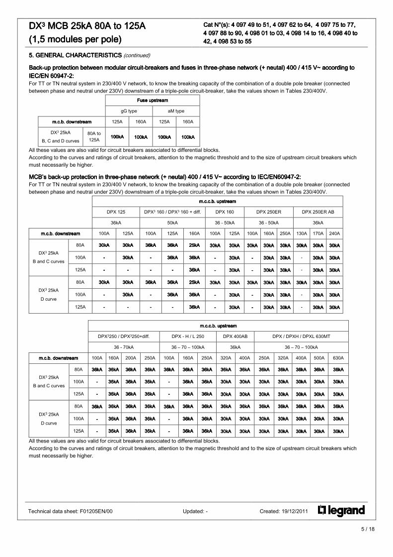
MCB’s backMCB’s backMCB’s backMCB’s back----up protection in up protection in up protection in up protection in threethreethreethree----phase network (+ neutal) 400 / 415 V~ according tophase network (+ neutal) 400 / 415 V~ according tophase network (+ neutal) 400 / 415 V~ according tophase network (+ neutal) 400 / 415 V~ according to IEC/EN60947IEC/EN60947IEC/EN60947IEC/EN60947----2:2:2:2: For TT or TN neutral system in 230/400 V network, to know the breaking capacity of the combination of a double pole breaker (connected between phase and neutral under 230V) downstream of a triple-pole circuit-breaker, take the values shown in Tables 230/400V.
m.c.c.m.c.c.m.c.c.m.c.c.b. upstreamb. upstreamb. upstreamb. upstream
DPX 125 DPX3 160 / DPX3 160 + diff. DPX 160 DPX 250ER DPX 250ER AB
36kA 50kA 36 - 50kA 36 - 50kA 36kA
m.c.b. downstreamm.c.b. downstreamm.c.b. downstreamm.c.b. downstream 100A 125A 100A 125A 160A 100A 125A 100A 160A 250A 130A 170A 240A
80A 30kA30kA30kA30kA 30kA30kA30kA30kA 36kA36kA36kA36kA 36kA36kA36kA36kA 25kA25kA25kA25kA 30kA30kA30kA30kA 30kA30kA30kA30kA 30kA30kA30kA30kA 30kA30kA30kA30kA 30kA30kA30kA30kA 30kA30kA30kA30kA 30kA30kA30kA30kA 30kA30kA30kA30kA
100A ---- 30kA30kA30kA30kA ---- 36kA36kA36kA36kA 36kA36kA36kA36kA ---- 30kA30kA30kA30kA ---- 30kA30kA30kA30kA 30kA30kA30kA30kA - 30kA30kA30kA30kA 30kA30kA30kA30kA DX3 25kA
B and C curves
125A ---- ---- ---- ---- 36kA36kA36kA36kA ---- 30kA30kA30kA30kA ---- 30kA30kA30kA30kA 30kA30kA30kA30kA - 30kA30kA30kA30kA 30kA30kA30kA30kA
80A 30kA30kA30kA30kA 30kA30kA30kA30kA 36kA36kA36kA36kA 36kA36kA36kA36kA 25kA25kA25kA25kA 30kA30kA30kA30kA 30kA30kA30kA30kA 30kA30kA30kA30kA 30kA30kA30kA30kA 30kA30kA30kA30kA 30kA30kA30kA30kA 30kA30kA30kA30kA 30kA30kA30kA30kA
100A ---- 30kA30kA30kA30kA ---- 36kA36kA36kA36kA 36kA36kA36kA36kA ---- 30kA30kA30kA30kA ---- 30kA30kA30kA30kA 30kA30kA30kA30kA - 30kA30kA30kA30kA 30kA30kA30kA30kA DX3 25kA
D curve 125A ---- ---- ---- ---- 36kA36kA36kA36kA ---- 30kA30kA30kA30kA ---- 30kA30kA30kA30kA 30kA30kA30kA30kA - 30kA30kA30kA30kA 30kA30kA30kA30kA
m.c.c.b. upstreamm.c.c.b. upstreamm.c.c.b. upstreamm.c.c.b. upstream
DPX3250 / DPX3250+diff. DPX - H / L 250 DPX 400AB DPX / DPXH / DPXL 630MT
36 - 70kA 36 – 70 – 100kA 36kA 36 – 70 – 100kA
m.c.b. downstreamm.c.b. downstreamm.c.b. downstreamm.c.b. downstream 100A 160A 200A 250A 100A 160A 250A 320A 400A 250A 320A 400A 500A 630A
80A 36kA36kA36kA36kA 36kA36kA36kA36kA 36kA36kA36kA36kA 36kA36kA36kA36kA 36kA36kA36kA36kA 36kA36kA36kA36kA 36kA36kA36kA36kA 36kA36kA36kA36kA 36kA36kA36kA36kA 36kA36kA36kA36kA 36kA36kA36kA36kA 36kA36kA36kA36kA 36kA36kA36kA36kA 36kA36kA36kA36kA
100A ---- 36kA36kA36kA36kA 36kA36kA36kA36kA 36kA36kA36kA36kA ---- 36kA36kA36kA36kA 36kA36kA36kA36kA 30kA30kA30kA30kA 30kA30kA30kA30kA 30kA30kA30kA30kA 30kA30kA30kA30kA 30kA30kA30kA30kA 30kA30kA30kA30kA 30kA30kA30kA30kA DX3 25kA
B and C curves 125A ---- 36kA36kA36kA36kA 36kA36kA36kA36kA 33336kA6kA6kA6kA ---- 36kA36kA36kA36kA 36kA36kA36kA36kA 30kA30kA30kA30kA 30kA30kA30kA30kA 30kA30kA30kA30kA 30kA30kA30kA30kA 30kA30kA30kA30kA 30kA30kA30kA30kA 30kA30kA30kA30kA
80A 36kA36kA36kA36kA 36kA36kA36kA36kA 36kA36kA36kA36kA 36kA36kA36kA36kA 36kA36kA36kA36kA 36kA36kA36kA36kA 36kA36kA36kA36kA 36kA36kA36kA36kA 36kA36kA36kA36kA 36kA36kA36kA36kA 36kA36kA36kA36kA 36kA36kA36kA36kA 36kA36kA36kA36kA 36kA36kA36kA36kA
100A ---- 36kA36kA36kA36kA 36kA36kA36kA36kA 36kA36kA36kA36kA ---- 36kA36kA36kA36kA 36kA36kA36kA36kA 30kA30kA30kA30kA 30kA30kA30kA30kA 30kA30kA30kA30kA 30kA30kA30kA30kA 30kA30kA30kA30kA 30kA30kA30kA30kA 30kA30kA30kA30kA DX3 25kA
D curve 125A ---- 36kA36kA36kA36kA 36kA36kA36kA36kA 36kA36kA36kA36kA ---- 36kA36kA36kA36kA 36kA36kA36kA36kA 30kA30kA30kA30kA 33330kA0kA0kA0kA 30kA30kA30kA30kA 30kA30kA30kA30kA 30kA30kA30kA30kA 30kA30kA30kA30kA 30kA30kA30kA30kA
All these values are also valid for circuit breakers associated to differential blocks. According to the curves and ratings of circuit breakers, attention to the magnetic threshold and to the size of upstream circuit breakers which must necessarily be higher.
Technical data sheet: F01205EN/00 Updated: - Created: 19/12/2011

6 / 18
DXDXDXDX3333 MCB 25kA 80A to 125A MCB 25kA 80A to 125A MCB 25kA 80A to 125A MCB 25kA 80A to 125A (1,5 modules per p(1,5 modules per p(1,5 modules per p(1,5 modules per poooole)le)le)le)
Cat N°(s): Cat N°(s): Cat N°(s): Cat N°(s): 4 097 49 to 51, 4 097 62 to 64, 4 097 75 to 77, 4 097 49 to 51, 4 097 62 to 64, 4 097 75 to 77, 4 097 49 to 51, 4 097 62 to 64, 4 097 75 to 77, 4 097 49 to 51, 4 097 62 to 64, 4 097 75 to 77, 4 097 88 to 90, 4 098 01 to 03, 4 04 097 88 to 90, 4 098 01 to 03, 4 04 097 88 to 90, 4 098 01 to 03, 4 04 097 88 to 90, 4 098 01 to 03, 4 098 14 to 16, 498 14 to 16, 498 14 to 16, 498 14 to 16, 4 098098098098 40 to 40 to 40 to 40 to 42, 4 098 53 to 5542, 4 098 53 to 5542, 4 098 53 to 5542, 4 098 53 to 55
5. GENERAL CHARACTERISTICS 5. GENERAL CHARACTERISTICS 5. GENERAL CHARACTERISTICS 5. GENERAL CHARACTERISTICS (continued):
BackBackBackBack----up protectionup protectionup protectionup protection between mod between mod between mod between modular circuitular circuitular circuitular circuit----breakers and fuses inbreakers and fuses inbreakers and fuses inbreakers and fuses in three three three three----phase network (+ neutal) 230 / 240 V~ according to phase network (+ neutal) 230 / 240 V~ according to phase network (+ neutal) 230 / 240 V~ according to phase network (+ neutal) 230 / 240 V~ according to IEC/EN 60947IEC/EN 60947IEC/EN 60947IEC/EN 60947----2:2:2:2:
Fuse upstreamFuse upstreamFuse upstreamFuse upstream
gG type aM type
m.c.b. downstreamm.c.b. downstreamm.c.b. downstreamm.c.b. downstream 125A 160A 125A 160A
DX3 25kA
B, C and D curves 80A to 125A 100kA100kA100kA100kA 100kA100kA100kA100kA 100kA100kA100kA100kA 100kA100kA100kA100kA
All these values are also valid for circuit breakers associated to differential blocks. According to the curves and ratings of circuit breakers, attention to the magnetic threshold and to the size of upstream circuit breakers which must necessarily be higher.
MCB’s back-up protection in three phase network (+ neutal) 230 / 240 V~ according to IEC/EN 60947-2: m.c.c.b. upstreamm.c.c.b. upstreamm.c.c.b. upstreamm.c.c.b. upstream
DPX3 160
DPX3 160 + diff. DPX 160 DPX 160 DPX 250ER DPX 250ER
50kA 36kA 50kA 36kA 50kA
m.c.b. downstreamm.c.b. downstreamm.c.b. downstreamm.c.b. downstream 100A 125A 160A 100A 160A 100A 160A 100A 160A 250A 100A 160A 250A
80A 65kA65kA65kA65kA 65kA65kA65kA65kA 65kA65kA65kA65kA ---- ---- 55kA55kA55kA55kA 55kA55kA55kA55kA ---- ---- ---- 55kA55kA55kA55kA 55kA55kA55kA55kA 55kA55kA55kA55kA
100A ---- 65kA65kA65kA65kA 65kA65kA65kA65kA ---- ---- ---- 55555555kAkAkAkA ---- ---- ---- ---- 55kA55kA55kA55kA 55kA55kA55kA55kA DX3 25kA
B and C curves
125A ---- ---- 65kA65kA65kA65kA ---- ---- ---- 55kA55kA55kA55kA ---- ---- ---- ---- 55kA55kA55kA55kA 55kA55kA55kA55kA
80A 65kA65kA65kA65kA 65kA65kA65kA65kA 65kA65kA65kA65kA ---- ---- 55kA55kA55kA55kA 55kA55kA55kA55kA ---- ---- ---- 55kA55kA55kA55kA 55kA55kA55kA55kA 55kA55kA55kA55kA
100A ---- 65kA65kA65kA65kA 65kA65kA65kA65kA ---- ---- ---- 55kA55kA55kA55kA ---- ---- ---- ---- 55kA55kA55kA55kA 55kA55kA55kA55kA DX3 25kA
D curve 125A ---- ---- 65kA65kA65kA65kA ---- ---- ---- 55kA55kA55kA55kA ---- ---- ---- ---- 55kA55kA55kA55kA 55kA55kA55kA55kA
m.c.c.b. upstreamm.c.c.b. upstreamm.c.c.b. upstreamm.c.c.b. upstream
DPX3 250
DPX3 250 + diff. DPX 250 DPX H / L 250 DPX 630MT
70kA 36kA 70 – 100kA 36kA
m.c.b. downstreamm.c.b. downstreamm.c.b. downstreamm.c.b. downstream 100A 160A 200A 250A 100A 160A 250A 100A 160A 250A 250A 320A 400A 500A 630A
80A 60kA60kA60kA60kA 60kA60kA60kA60kA 60kA60kA60kA60kA 60kA60kA60kA60kA 55kA55kA55kA55kA 55kA55kA55kA55kA 55kA55kA55kA55kA 60kA60kA60kA60kA 60kA60kA60kA60kA 60kA60kA60kA60kA 55kA55kA55kA55kA 55kA55kA55kA55kA 55kA55kA55kA55kA 55kA55kA55kA55kA 55kA55kA55kA55kA
100A ---- 60kA60kA60kA60kA 60kA60kA60kA60kA 60kA60kA60kA60kA ---- 55kA55kA55kA55kA 55kA55kA55kA55kA ---- 60kA60kA60kA60kA 60kA60kA60kA60kA 55kA55kA55kA55kA 55kA55kA55kA55kA 55kA55kA55kA55kA 55kA55kA55kA55kA 55kA55kA55kA55kA DX3 25kA
B and C curves
125A ---- 60kA60kA60kA60kA 60kA60kA60kA60kA 60kA60kA60kA60kA ---- 55kA55kA55kA55kA 55kA55kA55kA55kA ---- 60kA60kA60kA60kA 60kA60kA60kA60kA 55kA55kA55kA55kA 55kA55kA55kA55kA 55kA55kA55kA55kA 55kA55kA55kA55kA 55kA55kA55kA55kA
80A 60kA60kA60kA60kA 60kA60kA60kA60kA 60kA60kA60kA60kA 60kA60kA60kA60kA 55kA55kA55kA55kA 55kA55kA55kA55kA 55kA55kA55kA55kA 60kA60kA60kA60kA 60kA60kA60kA60kA 60kA60kA60kA60kA 55kA55kA55kA55kA 55kA55kA55kA55kA 55555555kAkAkAkA 55kA55kA55kA55kA 55kA55kA55kA55kA
100A ---- 60kA60kA60kA60kA 60kA60kA60kA60kA 60kA60kA60kA60kA ---- 55kA55kA55kA55kA 55kA55kA55kA55kA ---- 60kA60kA60kA60kA 60kA60kA60kA60kA 55kA55kA55kA55kA 55kA55kA55kA55kA 55kA55kA55kA55kA 55kA55kA55kA55kA 55kA55kA55kA55kA DX3 25kA
D curve 125A ---- 60kA60kA60kA60kA 60kA60kA60kA60kA 60kA60kA60kA60kA ---- 55kA55kA55kA55kA 55kA55kA55kA55kA ---- 60kA60kA60kA60kA 60kA60kA60kA60kA 55kA55kA55kA55kA 55kA55kA55kA55kA 55kA55kA55kA55kA 55kA55kA55kA55kA 55kA55kA55kA55kA
All these values are also valid for circuit breakers associated to differential blocks. According to the curves and ratings of circuit breakers, attention to the magnetic threshold and to the size of upstream circuit breakers which must necessarily be higher.
Technical data sheet: F01205EN/00 Updated: - Created: 19/12/2011

7 / 18
DXDXDXDX3333 MCB 25kA 80A MCB 25kA 80A MCB 25kA 80A MCB 25kA 80A to 125Ato 125Ato 125Ato 125A (1,5 modules per p(1,5 modules per p(1,5 modules per p(1,5 modules per poooole)le)le)le)
Cat N°(s): Cat N°(s): Cat N°(s): Cat N°(s): 4 097 49 to 51, 4 097 62 to 64, 4 097 75 to 77, 4 097 49 to 51, 4 097 62 to 64, 4 097 75 to 77, 4 097 49 to 51, 4 097 62 to 64, 4 097 75 to 77, 4 097 49 to 51, 4 097 62 to 64, 4 097 75 to 77, 4 097 88 to 90, 4 098 01 to 03, 4 098 14 to 16, 44 097 88 to 90, 4 098 01 to 03, 4 098 14 to 16, 44 097 88 to 90, 4 098 01 to 03, 4 098 14 to 16, 44 097 88 to 90, 4 098 01 to 03, 4 098 14 to 16, 4 098098098098 40 to 40 to 40 to 40 to 42, 4 098 53 to 5542, 4 098 53 to 5542, 4 098 53 to 5542, 4 098 53 to 55
5. GENERAL CHARACTERISTICS5. GENERAL CHARACTERISTICS5. GENERAL CHARACTERISTICS5. GENERAL CHARACTERISTICS (continued)
Selectivity between two levels of protectiSelectivity between two levels of protectiSelectivity between two levels of protectiSelectivity between two levels of protectionononon . The downstream circuit breaker must always have a magnetic threshold and a rated current lower than those of the upstream protection. . Selectivity is indicated total (T) if there is selectivity up to the value of breaking capacity (according to IEC / EN 60947-2) of the downstream circuit breaker.
Selectivity between Selectivity between Selectivity between Selectivity between MCB and MCB or MCCB upstreamMCB and MCB or MCCB upstreamMCB and MCB or MCCB upstreamMCB and MCB or MCCB upstream:::: . Selectivity limit at 400V~: values in Ampere.
m.c.c.b. upstreamm.c.c.b. upstreamm.c.c.b. upstreamm.c.c.b. upstream
DX325kA
Curve D
DPX3160E / B / N
DPX3160E / B / N + diff. DPX 160 DPX 250ER
16 – 25kA 16 - 25 - 50kA 25 – 36 – 50kA 25 – 36 – 50kA
m.c.b. downstreamm.c.b. downstreamm.c.b. downstreamm.c.b. downstream 100A 125A 125A 160A 160A 160A 250A
80A 1200120012001200 1500150015001500 5000500050005000 6000600060006000 5000500050005000 5000500050005000 5000500050005000
100A ---- 1500150015001500 ---- 5000500050005000 4000400040004000 4000400040004000 4000400040004000 DX3 25kA
B and C curves
125A ---- ---- ---- 3000300030003000 2000200020002000 2000200020002000 3000300030003000
80A 1212121200000000 1500150015001500 5000500050005000 6000600060006000 4000400040004000 4000400040004000 5000500050005000
100A ---- 1500150015001500 ---- 5000500050005000 3000300030003000 3000300030003000 4000400040004000 DX3 25kA
D curve 125A ---- ---- ---- 3000300030003000 1500150015001500 1500150015001500 2000200020002000
m.c.c.b. upstreamm.c.c.b. upstreamm.c.c.b. upstreamm.c.c.b. upstream
DPX 250 / H / L DPX 250ER AB DPX3 250
DPX3 250 + diff DPX 400AB
25 - 70 - 100kA 36kA 25 - 36 - 70kA 36kA
m.c.b. downstreamm.c.b. downstreamm.c.b. downstreamm.c.b. downstream 160A 250A 240A 100A 160A 200A 250A 320A 400A
80A 8000800080008000 TTTT TTTT 4000400040004000 TTTT TTTT TTTT TTTT TTTT
100A 6000600060006000 TTTT TTTT ---- TTTT TTTT TTTT TTTT TTTT DX3 25kA
B and C curves
125A 3000300030003000 8000800080008000 TTTT ---- TTTT TTTT TTTT TTTT TTTT
80A 8000800080008000 TTTT TTTT ---- TTTT TTTT TTTT TTTT TTTT
100A 6000600060006000 TTTT TTTT ---- TTTT TTTT TTTT TTTT TTTT DX3 25kA
D curve 125A 3000300030003000 7000700070007000 TTTT ---- ---- TTTT TTTT TTTT TTTT
SSSSelectivity between modular circuit breakers and fuses:electivity between modular circuit breakers and fuses:electivity between modular circuit breakers and fuses:electivity between modular circuit breakers and fuses: . Selectivity limit at 400V~: values in Ampere.
Fuse. upstreamFuse. upstreamFuse. upstreamFuse. upstream
aM type gG type
m.c.b. downstreamm.c.b. downstreamm.c.b. downstreamm.c.b. downstream 100A 125A 160A 100A 125A 160A
80A 3000300030003000 6000600060006000 8000800080008000 3000300030003000 3000300030003000 4000400040004000
100A ---- 4040404000000000 5000500050005000 ---- 3000300030003000 3500350035003500 DX3 25kA
B and C curves
125° ---- ---- 4000400040004000 ---- ---- 3500350035003500
80A ---- 4000400040004000 5000500050005000 ---- 2000200020002000 3000300030003000
100A ---- ---- 4000400040004000 ---- ---- 2000200020002000 DX3 25kA
D curve 125A ---- ---- ---- ---- ---- ----
Technical data sheet: F01205EN/00 Updated: - Created: 19/12/2011

8 / 18
DXDXDXDX3333 MCB 25kA 80A to 125A MCB 25kA 80A to 125A MCB 25kA 80A to 125A MCB 25kA 80A to 125A (1,5 modules per p(1,5 modules per p(1,5 modules per p(1,5 modules per poooolllle)e)e)e)
Cat N°(s): Cat N°(s): Cat N°(s): Cat N°(s): 4 097 49 to 51, 4 097 62 to 64, 4 097 75 to 77, 4 097 49 to 51, 4 097 62 to 64, 4 097 75 to 77, 4 097 49 to 51, 4 097 62 to 64, 4 097 75 to 77, 4 097 49 to 51, 4 097 62 to 64, 4 097 75 to 77, 4 097 88 to 90, 4 098 01 to 03, 4 098 14 to 16, 44 097 88 to 90, 4 098 01 to 03, 4 098 14 to 16, 44 097 88 to 90, 4 098 01 to 03, 4 098 14 to 16, 44 097 88 to 90, 4 098 01 to 03, 4 098 14 to 16, 4 098098098098 40 to 40 to 40 to 40 to 42, 4 098 53 to 5542, 4 098 53 to 5542, 4 098 53 to 5542, 4 098 53 to 55
6. CONFORMITIES AND APPROVALS6. CONFORMITIES AND APPROVALS6. CONFORMITIES AND APPROVALS6. CONFORMITIES AND APPROVALS
Compliance to standardsCompliance to standardsCompliance to standardsCompliance to standards:::: . Standard: IEC/EN 60947-2. . CEE guidelines : 73/23/CEE + 93/68/CEE . Legrand circuit-breakers can be used under the conditions of use as defined by IEC / EN 60947. . The performance of circuit breakers can be influenced by particular climates: hot dry, cold dry, hot humid, salt fog atmosphere
ClassificationClassificationClassificationClassification according to Annex Q according to Annex Q according to Annex Q according to Annex Q (standard IEC/EN 60947(standard IEC/EN 60947(standard IEC/EN 60947(standard IEC/EN 60947----1)1)1)1) :::: . Category C with a range test temperature -25 °C / +70 °C . salt fog atmosphere according IEC 60068-2-52
Respect of the environment Respect of the environment Respect of the environment Respect of the environment –––– Compliance with CEE directives: Compliance with CEE directives: Compliance with CEE directives: Compliance with CEE directives: . Compliance with Directive 2002/95/EC of 27/01/03 called "RoHS" which provides for the banning of hazardous substances such as lead, mercury, cadmium, hexavalent chromium, brominated flame retardants polybrominated biphenyls (PBBs) and polybrominated diphenyl ethers (PBDEs) from 1st July 2006 . Compliance with Directive 91/338/CEE of 18/06/91 and Decree 94-647 of 27/07/04
Plastic materialsPlastic materialsPlastic materialsPlastic materials : : : : . Halogens-free plastic materials. . Marking of parts according to ISO 11469 and ISO 1043.
Packaging:Packaging:Packaging:Packaging: . Design and manufacture of packaging in accordance with Decree 98-638 of 07.20.98 and Directive 94/62/EC
Technical data sheet: F01205EN/00 Updated: - Created: 19/12/2011
9 / 18
DXDXDXDX3333 MCB 25kA 80A to 125A MCB 25kA 80A to 125A MCB 25kA 80A to 125A MCB 25kA 80A to 125A (1,5 modules per p(1,5 modules per p(1,5 modules per p(1,5 modules per poooole)le)le)le)
Cat N°(s): Cat N°(s): Cat N°(s): Cat N°(s): 4 097 49 to 51, 4 097 62 to 64, 4 097 75 to 77, 4 097 49 to 51, 4 097 62 to 64, 4 097 75 to 77, 4 097 49 to 51, 4 097 62 to 64, 4 097 75 to 77, 4 097 49 to 51, 4 097 62 to 64, 4 097 75 to 77, 4 097 88 to 90,4 097 88 to 90,4 097 88 to 90,4 097 88 to 90, 4 098 01 to 03, 4 098 14 to 16, 4 4 098 01 to 03, 4 098 14 to 16, 4 4 098 01 to 03, 4 098 14 to 16, 4 4 098 01 to 03, 4 098 14 to 16, 4 098098098098 40 to 40 to 40 to 40 to 42, 4 098 53 to 5542, 4 098 53 to 5542, 4 098 53 to 5542, 4 098 53 to 55
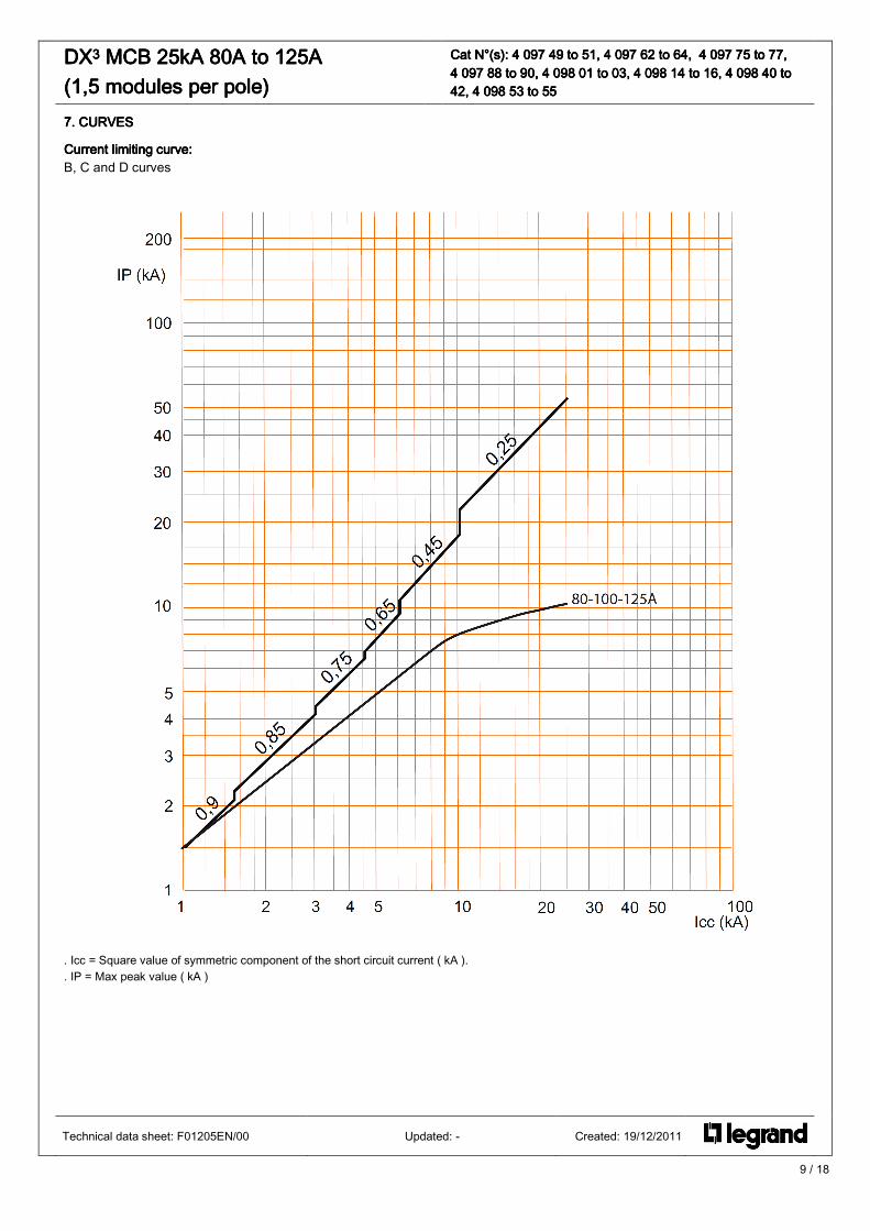
7. CURVES7. CURVES7. CURVES7. CURVES
Current limiting curve:Current limiting curve:Current limiting curve:Current limiting curve: B, C and D curves
. Icc = Square value of symmetric component of the short circuit current ( kA ). . IP = Max peak value ( kA )
Technical data sheet: F01205EN/00 Updated: - Created: 19/12/2011

10 / 18
DXDXDXDX3333 MCB 25kA 80A to 125A MCB 25kA 80A to 125A MCB 25kA 80A to 125A MCB 25kA 80A to 125A (1,5 modules per p(1,5 modules per p(1,5 modules per p(1,5 modules per poooole)le)le)le)
Cat N°(s): Cat N°(s): Cat N°(s): Cat N°(s): 4 097 49 to 51, 4 097 62 to 64, 4 097 75 to 77, 4 097 49 to 51, 4 097 62 to 64, 4 097 75 to 77, 4 097 49 to 51, 4 097 62 to 64, 4 097 75 to 77, 4 097 49 to 51, 4 097 62 to 64, 4 097 75 to 77, 4 097 88 to 90, 4 098 01 to 03, 4 098 14 to 16, 44 097 88 to 90, 4 098 01 to 03, 4 098 14 to 16, 44 097 88 to 90, 4 098 01 to 03, 4 098 14 to 16, 44 097 88 to 90, 4 098 01 to 03, 4 098 14 to 16, 4 098098098098 40 to 40 to 40 to 40 to 42, 4 098 53 to 5542, 4 098 53 to 5542, 4 098 53 to 5542, 4 098 53 to 55
7. CURVES7. CURVES7. CURVES7. CURVES (continued)
Operating characteristic of circuit breakers BOperating characteristic of circuit breakers BOperating characteristic of circuit breakers BOperating characteristic of circuit breakers B curvecurvecurvecurve::::
Technical data sheet: F01205EN/00 Updated: - Created: 19/12/2011
11 / 18
DXDXDXDX3333 MCB 25kA 80A to 125A MCB 25kA 80A to 125A MCB 25kA 80A to 125A MCB 25kA 80A to 125A (1,5 modules per p(1,5 modules per p(1,5 modules per p(1,5 modules per poooole)le)le)le)
Cat N°(s): Cat N°(s): Cat N°(s): Cat N°(s): 4 097 49 to 51, 4 097 62 to 64, 4 097 75 to 77, 4 097 49 to 51, 4 097 62 to 64, 4 097 75 to 77, 4 097 49 to 51, 4 097 62 to 64, 4 097 75 to 77, 4 097 49 to 51, 4 097 62 to 64, 4 097 75 to 77, 4 094 094 094 097 88 to 90, 4 098 01 to 03, 4 098 14 to 16, 47 88 to 90, 4 098 01 to 03, 4 098 14 to 16, 47 88 to 90, 4 098 01 to 03, 4 098 14 to 16, 47 88 to 90, 4 098 01 to 03, 4 098 14 to 16, 4 098098098098 40 to 40 to 40 to 40 to 42, 4 098 53 to 5542, 4 098 53 to 5542, 4 098 53 to 5542, 4 098 53 to 55
7. CURVES7. CURVES7. CURVES7. CURVES (continued)
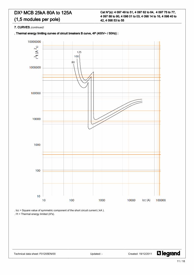
. . . . Thermal energy limiting curves Thermal energy limiting curves Thermal energy limiting curves Thermal energy limiting curves of circuit breakers Bof circuit breakers Bof circuit breakers Bof circuit breakers B curve curve curve curve, 4P (400V~ / 50Hz), 4P (400V~ / 50Hz), 4P (400V~ / 50Hz), 4P (400V~ / 50Hz) ::::
. Icc = Square value of symmetric component of the short circuit current ( kA ). . I2t = Thermal energy limited (A²s).
Technical data sheet: F01205EN/00 Updated: - Created: 19/12/2011

12 / 18
DXDXDXDX3333 MCB 25kA 80A to 125A MCB 25kA 80A to 125A MCB 25kA 80A to 125A MCB 25kA 80A to 125A (1,5 modules per p(1,5 modules per p(1,5 modules per p(1,5 modules per poooole)le)le)le)
Cat N°(s): Cat N°(s): Cat N°(s): Cat N°(s): 4 097 49 to 51, 4 097 62 to 64, 4 097 75 to 77, 4 097 49 to 51, 4 097 62 to 64, 4 097 75 to 77, 4 097 49 to 51, 4 097 62 to 64, 4 097 75 to 77, 4 097 49 to 51, 4 097 62 to 64, 4 097 75 to 77, 4 097 88 to 90, 4 098 4 097 88 to 90, 4 098 4 097 88 to 90, 4 098 4 097 88 to 90, 4 098 01 to 03, 4 098 14 to 16, 401 to 03, 4 098 14 to 16, 401 to 03, 4 098 14 to 16, 401 to 03, 4 098 14 to 16, 4 098098098098 40 to 40 to 40 to 40 to 42, 4 098 53 to 5542, 4 098 53 to 5542, 4 098 53 to 5542, 4 098 53 to 55
7. CURVES7. CURVES7. CURVES7. CURVES (continued)
Operating characteristic of circuit breakers COperating characteristic of circuit breakers COperating characteristic of circuit breakers COperating characteristic of circuit breakers C curvecurvecurvecurve::::
Technical data sheet: F01205EN/00 Updated: - Created: 19/12/2011
13 / 18
DXDXDXDX3333 MCB 25kA 80A to 125A MCB 25kA 80A to 125A MCB 25kA 80A to 125A MCB 25kA 80A to 125A (1,5 modules per p(1,5 modules per p(1,5 modules per p(1,5 modules per poooole)le)le)le)
Cat N°(s): Cat N°(s): Cat N°(s): Cat N°(s): 4 097 49 to 51, 4 097 62 to 64, 4 097 75 to 77, 4 097 49 to 51, 4 097 62 to 64, 4 097 75 to 77, 4 097 49 to 51, 4 097 62 to 64, 4 097 75 to 77, 4 097 49 to 51, 4 097 62 to 64, 4 097 75 to 77, 4 097 88 to 90, 4 098 01 to 03, 4 098 14 to 16, 44 097 88 to 90, 4 098 01 to 03, 4 098 14 to 16, 44 097 88 to 90, 4 098 01 to 03, 4 098 14 to 16, 44 097 88 to 90, 4 098 01 to 03, 4 098 14 to 16, 4 098098098098 40 to 40 to 40 to 40 to 42, 4 098 53 to 5542, 4 098 53 to 5542, 4 098 53 to 5542, 4 098 53 to 55
7. CURVES7. CURVES7. CURVES7. CURVES (continued)
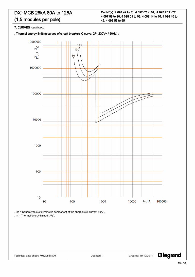
. . . . Thermal energy limiting curves Thermal energy limiting curves Thermal energy limiting curves Thermal energy limiting curves of circuit breakers Cof circuit breakers Cof circuit breakers Cof circuit breakers C curve curve curve curve, 2P (230V~ / 50Hz), 2P (230V~ / 50Hz), 2P (230V~ / 50Hz), 2P (230V~ / 50Hz) ::::
. Icc = Square value of symmetric component of the short circuit current ( kA ). . I2t = Thermal energy limited (A²s).
Technical data sheet: F01205EN/00 Updated: - Created: 19/12/2011
14 / 18
DXDXDXDX3333 MCB 25kA 80A to 125A MCB 25kA 80A to 125A MCB 25kA 80A to 125A MCB 25kA 80A to 125A (1,5 modules per p(1,5 modules per p(1,5 modules per p(1,5 modules per poooole)le)le)le)
Cat N°(s): Cat N°(s): Cat N°(s): Cat N°(s): 4444 097 49 to 51, 4 097 62 to 64, 4 097 75 to 77, 097 49 to 51, 4 097 62 to 64, 4 097 75 to 77, 097 49 to 51, 4 097 62 to 64, 4 097 75 to 77, 097 49 to 51, 4 097 62 to 64, 4 097 75 to 77, 4 097 88 to 90, 4 098 01 to 03, 4 098 14 to 16, 44 097 88 to 90, 4 098 01 to 03, 4 098 14 to 16, 44 097 88 to 90, 4 098 01 to 03, 4 098 14 to 16, 44 097 88 to 90, 4 098 01 to 03, 4 098 14 to 16, 4 098098098098 40 to 40 to 40 to 40 to 42, 4 098 53 to 5542, 4 098 53 to 5542, 4 098 53 to 5542, 4 098 53 to 55
7. CURVES7. CURVES7. CURVES7. CURVES (continued)
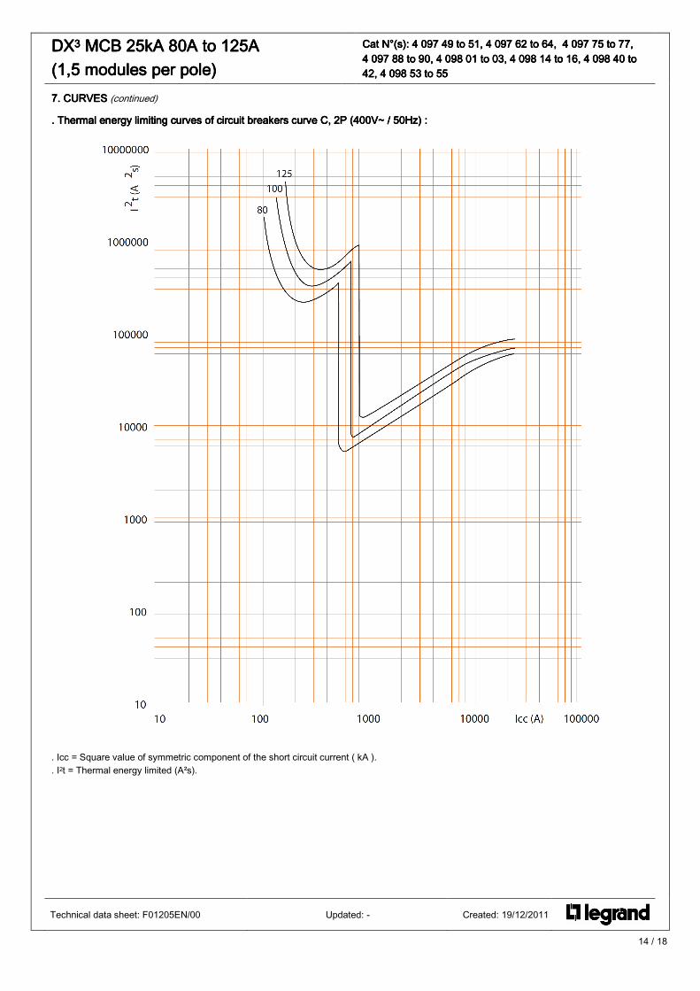
. . . . Thermal energy limiting curves Thermal energy limiting curves Thermal energy limiting curves Thermal energy limiting curves of circuit breakers curve C, 2P (400V~ / 50Hz)of circuit breakers curve C, 2P (400V~ / 50Hz)of circuit breakers curve C, 2P (400V~ / 50Hz)of circuit breakers curve C, 2P (400V~ / 50Hz) ::::
. Icc = Square value of symmetric component of the short circuit current ( kA ). . I2t = Thermal energy limited (A²s).
Technical data sheet: F01205EN/00 Updated: - Created: 19/12/2011

15 / 18
DXDXDXDX3333 MCB 25kA 80A to 125A MCB 25kA 80A to 125A MCB 25kA 80A to 125A MCB 25kA 80A to 125A (1,5 modules per p(1,5 modules per p(1,5 modules per p(1,5 modules per poooole)le)le)le)
Cat N°(s): Cat N°(s): Cat N°(s): Cat N°(s): 4 097 49 to 51, 4 04 097 49 to 51, 4 04 097 49 to 51, 4 04 097 49 to 51, 4 097 62 to 64, 4 097 75 to 77, 97 62 to 64, 4 097 75 to 77, 97 62 to 64, 4 097 75 to 77, 97 62 to 64, 4 097 75 to 77, 4 097 88 to 90, 4 098 01 to 03, 4 098 14 to 16, 44 097 88 to 90, 4 098 01 to 03, 4 098 14 to 16, 44 097 88 to 90, 4 098 01 to 03, 4 098 14 to 16, 44 097 88 to 90, 4 098 01 to 03, 4 098 14 to 16, 4 098098098098 40 to 40 to 40 to 40 to 42, 4 098 53 to 5542, 4 098 53 to 5542, 4 098 53 to 5542, 4 098 53 to 55
7. CURVES7. CURVES7. CURVES7. CURVES (continued)
. . . . Thermal energy limiting curves Thermal energy limiting curves Thermal energy limiting curves Thermal energy limiting curves of circuit breakers Cof circuit breakers Cof circuit breakers Cof circuit breakers C curve curve curve curve, 1P / 3P / 4P (400V~ / 50Hz), 1P / 3P / 4P (400V~ / 50Hz), 1P / 3P / 4P (400V~ / 50Hz), 1P / 3P / 4P (400V~ / 50Hz) ::::
. Icc = Square value of symmetric component of the short circuit current ( kA ). . I2t = Thermal energy limited (A²s).
Technical data sheet: F01205EN/00 Updated: - Created: 19/12/2011
16 / 18
DXDXDXDX3333 MCB 25kA 80A to 125A MCB 25kA 80A to 125A MCB 25kA 80A to 125A MCB 25kA 80A to 125A (1,5 modules per p(1,5 modules per p(1,5 modules per p(1,5 modules per poooole)le)le)le)
Cat N°(s): Cat N°(s): Cat N°(s): Cat N°(s): 4 097 49 to 51, 4 097 62 to 4 097 49 to 51, 4 097 62 to 4 097 49 to 51, 4 097 62 to 4 097 49 to 51, 4 097 62 to 64, 4 097 75 to 77, 64, 4 097 75 to 77, 64, 4 097 75 to 77, 64, 4 097 75 to 77, 4 097 88 to 90, 4 098 01 to 03, 4 098 14 to 16, 44 097 88 to 90, 4 098 01 to 03, 4 098 14 to 16, 44 097 88 to 90, 4 098 01 to 03, 4 098 14 to 16, 44 097 88 to 90, 4 098 01 to 03, 4 098 14 to 16, 4 098098098098 40 to 40 to 40 to 40 to 42, 4 098 53 to 5542, 4 098 53 to 5542, 4 098 53 to 5542, 4 098 53 to 55
7. CURVES7. CURVES7. CURVES7. CURVES (continued)
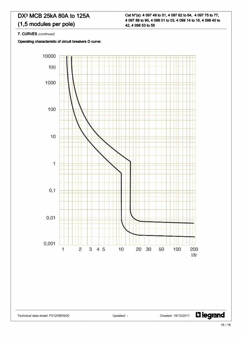
Operating characteristic of circuit breakers DOperating characteristic of circuit breakers DOperating characteristic of circuit breakers DOperating characteristic of circuit breakers D curve curve curve curve::::
Technical data sheet: F01205EN/00 Updated: - Created: 19/12/2011

17 / 18
DXDXDXDX3333 MCB 25kA 80A to 125A MCB 25kA 80A to 125A MCB 25kA 80A to 125A MCB 25kA 80A to 125A (1,5 modules per p(1,5 modules per p(1,5 modules per p(1,5 modules per poooole)le)le)le)
Cat N°(s): Cat N°(s): Cat N°(s): Cat N°(s): 4 097 49 to 51, 4 097 62 to 64, 4 097 75 to 77, 4 097 49 to 51, 4 097 62 to 64, 4 097 75 to 77, 4 097 49 to 51, 4 097 62 to 64, 4 097 75 to 77, 4 097 49 to 51, 4 097 62 to 64, 4 097 75 to 77, 4 097 88 to 90, 4 098 01 to 03, 4 098 14 to 16, 44 097 88 to 90, 4 098 01 to 03, 4 098 14 to 16, 44 097 88 to 90, 4 098 01 to 03, 4 098 14 to 16, 44 097 88 to 90, 4 098 01 to 03, 4 098 14 to 16, 4 098098098098 40 to 40 to 40 to 40 to 42, 4 098 53 to 5542, 4 098 53 to 5542, 4 098 53 to 5542, 4 098 53 to 55
7. CURVES7. CURVES7. CURVES7. CURVES (continued)
. . . . Thermal energy limiting curves Thermal energy limiting curves Thermal energy limiting curves Thermal energy limiting curves of circuof circuof circuof circuit breakers Dit breakers Dit breakers Dit breakers D curve curve curve curve, 3P / 4P (400V~ / 50Hz), 3P / 4P (400V~ / 50Hz), 3P / 4P (400V~ / 50Hz), 3P / 4P (400V~ / 50Hz) ::::
. Icc = Square value of symmetric component of the short circuit current ( kA ). . I2t = Thermal energy limited (A²s).
Technical data sheet: F01205EN/00 Updated: - Created: 19/12/2011

18 / 18
DXDXDXDX3333 MCB 25kA MCB 25kA MCB 25kA MCB 25kA 80A to 125A 80A to 125A 80A to 125A 80A to 125A (1,5 modules per p(1,5 modules per p(1,5 modules per p(1,5 modules per poooole)le)le)le)
Cat N°(s): Cat N°(s): Cat N°(s): Cat N°(s): 4 097 49 to 51, 4 097 62 to 64, 4 097 75 to 77, 4 097 49 to 51, 4 097 62 to 64, 4 097 75 to 77, 4 097 49 to 51, 4 097 62 to 64, 4 097 75 to 77, 4 097 49 to 51, 4 097 62 to 64, 4 097 75 to 77, 4 097 88 to 90, 4 098 01 to 03, 4 098 14 to 16, 44 097 88 to 90, 4 098 01 to 03, 4 098 14 to 16, 44 097 88 to 90, 4 098 01 to 03, 4 098 14 to 16, 44 097 88 to 90, 4 098 01 to 03, 4 098 14 to 16, 4 098098098098 40 to 40 to 40 to 40 to 42, 4 098 53 to 5542, 4 098 53 to 5542, 4 098 53 to 5542, 4 098 53 to 55
8. AUXILIARIES AND ACCESSORIES8. AUXILIARIES AND ACCESSORIES8. AUXILIARIES AND ACCESSORIES8. AUXILIARIES AND ACCESSORIES
AddAddAddAdd----on modules 125 Aon modules 125 Aon modules 125 Aon modules 125 A :::: Add on module
mcb 2P 3P 4P
2P XXXX ---- ----
3P ---- XXXX ----
4P ---- ---- XXXX
Wiring accessories:Wiring accessories:Wiring accessories:Wiring accessories: . Sealable screw cover (cat n° 4 063 06). . Insulating shields (cat n° 4 063 12) . Aluminium terminal 95 mm² max (cat. n° 4 063 11)
Signal auxiliaries:Signal auxiliaries:Signal auxiliaries:Signal auxiliaries: . Auxiliary contact (½ module – cat n° 4 062 58). . Fault signalling changeover switch (½ module – cat n° 4 062 60). . Auxiliary contact modifiable in default signal (½ module – cat n° 4 062 62). . Auxiliary contact + fault signalling switch - can be modified to 2 auxiliary contacts (1 module - cat n° 4 062 66).
Control auxiliaries:Control auxiliaries:Control auxiliaries:Control auxiliaries: . Shunt releases (1 module - cat n°. 4 062 76 / 78). . Under voltage release (1 module - cat n° 4 062 80 / 82). . Autonomous shunt trip for NC push-button (1 module - cat n°. 4 062 87).
Possible combinations of auxiliaries and MCBs:Possible combinations of auxiliaries and MCBs:Possible combinations of auxiliaries and MCBs:Possible combinations of auxiliaries and MCBs: . The auxiliaries are installed to the left of the MCBs . Maximum number of auxiliaries = 3 . Maximum number of 1 module signalling auxiliaries = 2 . Maximum number of control auxiliaries (Cat. Nos. 4 062 76 to 4 062 87) = 1 . The control auxiliary (Cat. Nos. 4 062 76 to 4 062 87) must manda-torily be placed to the left of the signalling auxiliaries (Cat. Nos. 4 062 58 to 4 062 66) where the auxiliaries from these 2 families are connected to the same MCB.
Sealing:Sealing:Sealing:Sealing: . Possible in ʺOpenʺ mode (OFF) or ʺCloseʺ mode (ON).
Locking options:Locking options:Locking options:Locking options: . By padlock (cat. n° 4 063 13 or 0 227 97), whit padlock support (cat. n° 4 063 03)
Installation software:Installation software:Installation software:Installation software: . XL PRO3
Technical data sheet: F01205EN/00 Updated: - Created: 19/12/2011


