
Dynamag / MagneSafe V5 IntelliHead USB / MagneSafe V5 Readers USB| Secure Card Reader Authenticators and OEM Products |
Programmer’s Reference (COMMANDS)
Page 1 of 152 (D998200176-11)
Dynamag /
MagneSafe V5 IntelliHead USB /
MagneSafe V5 Readers USB Secure Card Reader Authenticators and OEM Products
Programmer’s Reference (COMMANDS)
June 2017
Manual Part Number:
D998200176-11
REGISTERED TO ISO 9001:2008

Dynamag / MagneSafe V5 IntelliHead USB / MagneSafe V5 Readers USB| Secure Card Reader Authenticators and OEM Products |
Programmer’s Reference (COMMANDS)
Page 2 of 152 (D998200176-11)
Copyright © 2006 - 2017 MagTek, Inc.
Printed in the United States of America
INFORMATION IN THIS PUBLICATION IS SUBJECT TO CHANGE WITHOUT NOTICE AND
MAY CONTAIN TECHNICAL INACCURACIES OR GRAPHICAL DISCREPANCIES. CHANGES
OR IMPROVEMENTS MADE TO THIS PRODUCT WILL BE UPDATED IN THE NEXT
PUBLICATION RELEASE. NO PART OF THIS DOCUMENT MAY BE REPRODUCED OR
TRANSMITTED IN ANY FORM OR BY ANY MEANS, ELECTRONIC OR MECHANICAL, FOR
ANY PURPOSE, WITHOUT THE EXPRESS WRITTEN PERMISSION OF MAGTEK, INC.
MagTek® is a registered trademark of MagTek, Inc.
MagnePrint® is a registered trademark of MagTek, Inc.
Magensa™ is a trademark of MagTek, Inc.
MagneSafe™ is a trademark of MagTek, Inc.
IntelliStripe® is a registered trademark of MagTek, Inc.
AAMVA™ is a trademark of AAMVA.
American Express® and EXPRESSPAY FROM AMERICAN EXPRESS® are registered trademarks of
American Express Marketing & Development Corp.
D-PAYMENT APPLICATION SPECIFICATION® is a registered trademark to Discover Financial
Services CORPORATION
MasterCard® is a registered trademark and PayPass™ and Tap & Go™ are trademarks of MasterCard
International Incorporated.
Visa® and Visa payWave® are registered trademarks of Visa International Service Association.
ANSI®, the ANSI logo, and numerous other identifiers containing "ANSI" are registered trademarks,
service marks, and accreditation marks of the American National Standards Institute (ANSI).
ISO® is a registered trademark of the International Organization for Standardization.
PCI Security Standards Council® is a registered trademark of the PCI Security Standards Council, LLC.
EMVCo™ and EMV™ are trademarks of EMVCo and its licensors.
UL™ and the UL logo are trademarks of UL LLC.
The Bluetooth® word mark and logos are registered trademarks owned by Bluetooth SIG, Inc. and any
use of such marks by MagTek is under license.
Apple Pay®, iPhone®, iPod®, and Mac® are registered trademarks of Apple Inc., registered in the U.S.
and other countries. App StoreSM is a service mark of Apple Inc., registered in the U.S. and other
countries. iPad™ is a trademark of Apple, Inc. IOS is a trademark or registered trademark of Cisco in
the U.S. and other countries and is used by Apple Inc. under license.
Microsoft® and Windows® are registered trademarks of Microsoft Corporation.
USB (Universal Serial Bus) Specification is Copyright © 1998 Compaq Computer Corporation, Intel
Corporation, Microsoft Corporation, NEC Corporation.
Keyboard Usage Definitions content is taken from Universal Serial Bus HID Usage Tables, Version 1.12,
Section 10, Keyboard/Keypad Page (0x07) ©1996-2005 USB Implementers’ Forum
Modifier Byte Definitions content is taken from Section 8.3 Report Format for Array Items, Device Class
Definition for Human Interface Devices (HID) Version 1.11, ©1996-2001 USB Implementers’ Forum,
All other system names and product names are the property of their respective owners.

Dynamag / MagneSafe V5 IntelliHead USB / MagneSafe V5 Readers USB| Secure Card Reader Authenticators and OEM Products |
Programmer’s Reference (COMMANDS)
Page 3 of 152 (D998200176-11)
Table 1-1 - Revisions
Rev Number Date Notes
10 May 05, 2017 Initial release derived from D100003048-14
11 June 14, 2017 Add other applicable products to title

Dynamag / MagneSafe V5 IntelliHead USB / MagneSafe V5 Readers USB| Secure Card Reader Authenticators and OEM Products |
Programmer’s Reference (COMMANDS)
Page 4 of 152 (D998200176-11)
LIMITED WARRANTY MagTek warrants that the products sold pursuant to this Agreement will perform in accordance with
MagTek’s published specifications. This warranty shall be provided only for a period of one year from
the date of the shipment of the product from MagTek (the “Warranty Period”). This warranty shall apply
only to the “Buyer” (the original purchaser, unless that entity resells the product as authorized by
MagTek, in which event this warranty shall apply only to the first repurchaser).
During the Warranty Period, should this product fail to conform to MagTek’s specifications, MagTek
will, at its option, repair or replace this product at no additional charge except as set forth below. Repair
parts and replacement products will be furnished on an exchange basis and will be either reconditioned or
new. All replaced parts and products become the property of MagTek. This limited warranty does not
include service to repair damage to the product resulting from accident, disaster, unreasonable use,
misuse, abuse, negligence, or modification of the product not authorized by MagTek. MagTek reserves
the right to examine the alleged defective goods to determine whether the warranty is applicable.
Without limiting the generality of the foregoing, MagTek specifically disclaims any liability or warranty
for goods resold in other than MagTek’s original packages, and for goods modified, altered, or treated
without authorization by MagTek.
Service may be obtained by delivering the product during the warranty period to MagTek (1710 Apollo
Court, Seal Beach, CA 90740). If this product is delivered by mail or by an equivalent shipping carrier,
the customer agrees to insure the product or assume the risk of loss or damage in transit, to prepay
shipping charges to the warranty service location, and to use the original shipping container or equivalent.
MagTek will return the product, prepaid, via a three (3) day shipping service. A Return Material
Authorization (“RMA”) number must accompany all returns. Buyers may obtain an RMA number by
contacting Technical Support at (888) 624-8350.
EACH BUYER UNDERSTANDS THAT THIS MAGTEK PRODUCT IS
OFFERED AS IS. MAGTEK MAKES NO OTHER WARRANTY, EXPRESS OR
IMPLIED, AND MAGTEK DISCLAIMS ANY WARRANTY OF ANY OTHER
KIND, INCLUDING ANY WARRANTY OF MERCHANTABILITY OR FITNESS
FOR A PARTICULAR PURPOSE.
IF THIS PRODUCT DOES NOT CONFORM TO MAGTEK’S
SPECIFICATIONS, THE SOLE REMEDY SHALL BE REPAIR OR
REPLACEMENT AS PROVIDED ABOVE. MAGTEK’S LIABILITY, IF ANY,
SHALL IN NO EVENT EXCEED THE TOTAL AMOUNT PAID TO MAGTEK
UNDER THIS AGREEMENT. IN NO EVENT WILL MAGTEK BE LIABLE TO
THE BUYER FOR ANY DAMAGES, INCLUDING ANY LOST PROFITS, LOST
SAVINGS, OR OTHER INCIDENTAL OR CONSEQUENTIAL DAMAGES
ARISING OUT OF THE USE OF, OR INABILITY TO USE, SUCH PRODUCT,
EVEN IF MAGTEK HAS BEEN ADVISED OF THE POSSIBILITY OF SUCH
DAMAGES, OR FOR ANY CLAIM BY ANY OTHER PARTY.

Dynamag / MagneSafe V5 IntelliHead USB / MagneSafe V5 Readers USB| Secure Card Reader Authenticators and OEM Products |
Programmer’s Reference (COMMANDS)
Page 5 of 152 (D998200176-11)
LIMITATION ON LIABILITY
EXCEPT AS PROVIDED IN THE SECTIONS RELATING TO MAGTEK’S LIMITED WARRANTY,
MAGTEK’S LIABILITY UNDER THIS AGREEMENT IS LIMITED TO THE CONTRACT PRICE OF
THIS PRODUCT.
MAGTEK MAKES NO OTHER WARRANTIES WITH RESPECT TO THE PRODUCT, EXPRESSED
OR IMPLIED, EXCEPT AS MAY BE STATED IN THIS AGREEMENT, AND MAGTEK
DISCLAIMS ANY IMPLIED WARRANTY, INCLUDING WITHOUT LIMITATION ANY IMPLIED
WARRANTY OF MERCHANTABILITY OR FITNESS FOR A PARTICULAR PURPOSE.
MAGTEK SHALL NOT BE LIABLE FOR CONTINGENT, INCIDENTAL, OR CONSEQUENTIAL
DAMAGES TO PERSONS OR PROPERTY. MAGTEK FURTHER LIMITS ITS LIABILITY OF ANY
KIND WITH RESPECT TO THE PRODUCT, INCLUDING ANY NEGLIGENCE ON ITS PART, TO
THE CONTRACT PRICE FOR THE GOODS.
MAGTEK’S SOLE LIABILITY AND BUYER’S EXCLUSIVE REMEDIES ARE STATED IN THIS
SECTION AND IN THE SECTION RELATING TO MAGTEK’S LIMITED WARRANTY.

Dynamag / MagneSafe V5 IntelliHead USB / MagneSafe V5 Readers USB| Secure Card Reader Authenticators and OEM Products |
Programmer’s Reference (COMMANDS)
Page 6 of 152 (D998200176-11)
FCC INFORMATION This device complies with Part 15 of the FCC Rules. Operation is subject to the following two
conditions: (1) This device may not cause harmful interference, and (2) This device must accept any
interference received, including interference that may cause undesired operation.
Note: This equipment has been tested and found to comply with the limits for a Class B digital device,
pursuant to part 15 of the FCC Rules. These limits are designed to provide reasonable protection against
harmful interference in a residential installation. This equipment generates, uses and can radiate radio
frequency energy and, if not installed and used in accordance with the instructions, may cause harmful
interference to radio communications. However, there is no guarantee that interference will not occur in a
particular installation. If this equipment does cause harmful interference to radio or television reception,
which can be determined by turning the equipment off and on, the user is encouraged to try to correct the
interference by one or more of the following measures:
Reorient or relocate the receiving antenna.
Increase the separation between the equipment and receiver.
Connect the equipment into an outlet on a circuit different from that to which the receiver is
connected.
Consult the dealer or an experienced radio/TV technician for help.
Caution: Any changes or modifications not expressly approved by the party responsible for
compliance could void the user’s authority to operate this equipment. RF Exposure: A
distance of 20 cm shall be maintained between the antenna and users, and the transmitter
may not be co-located with any other transmitter or antenna.
CUR/UR This product is recognized per Underwriter Laboratories and Canadian Underwriter Laboratories 1950.
CANADIAN DOC STATEMENT This digital apparatus does not exceed the Class B limits for radio noise from digital apparatus set out in
the Radio Interference Regulations of the Canadian Department of Communications.
Le présent appareil numérique n’émet pas de bruits radioélectriques dépassant les limites applicables aux
appareils numériques de la classe B prescrites dans le Réglement sur le brouillage radioélectrique édicté
par le ministère des Communications du Canada.
This Class B digital apparatus complies with Canadian ICES-003.
Cet appareil numérique de la classe B est conformé à la norme NMB-003 du Canada.
CE STANDARDS Testing for compliance with CE requirements was performed by an independent laboratory. The unit
under test was found compliant with standards established for Class B devices.

Dynamag / MagneSafe V5 IntelliHead USB / MagneSafe V5 Readers USB| Secure Card Reader Authenticators and OEM Products |
Programmer’s Reference (COMMANDS)
Page 7 of 152 (D998200176-11)
UL/CSA This product is recognized per UL 60950-1, 2nd Edition, 2011-12-19 (Information Technology
Equipment - Safety - Part 1: General Requirements), CSA C22.2 No. 60950-1-07, 2nd Edition,
2011-12 (Information Technology Equipment - Safety - Part 1: General Requirements).
ROHS STATEMENT When ordered as RoHS compliant, this product meets the Electrical and Electronic Equipment (EEE)
Reduction of Hazardous Substances (RoHS) European Directive 2002/95/EC. The marking is clearly
recognizable, either as written words like “Pb-free,” “lead-free,” or as another clear symbol ( ).
1 - Table of Contents
Dynamag / MagneSafe V5 IntelliHead USB / MagneSafe V5 Readers USB| Secure Card Reader Authenticators and OEM Products |
Programmer’s Reference (COMMANDS)
Page 8 of 152 (D998200176-11)
1 Table of Contents Limited Warranty .............................................................................................................................................. 4
FCC Information ................................................................................................................................................ 6
CUR/UR............................................................................................................................................................... 6
CANADIAN DOC STATEMENT ........................................................................................................................... 6
CE STANDARDS ................................................................................................................................................. 6
UL/CSA ............................................................................................................................................................... 7
RoHS STATEMENT ............................................................................................................................................. 7
1 Table of Contents ...................................................................................................................................... 8
2 Introduction ............................................................................................................................................. 13
2.1 About This Document .................................................................................................................... 13
2.2 About APIs ....................................................................................................................................... 13
2.3 About Terminology ......................................................................................................................... 13
2.4 About Connections and Data Formats ........................................................................................ 15
2.5 About Device Features .................................................................................................................. 17
3 Connection Types .................................................................................................................................... 19
3.1 How to Use USB Connections (USB, Proprietary Wireless) ...................................................... 19
3.1.1 About USB Reports, Usages, Usage Pages, and Usage IDs ............................................. 20
3.1.2 How to Send Commands On the USB Connection ............................................................ 21
3.1.3 How to Receive Data On the USB Connection (HID) ......................................................... 23
3.1.4 How to Use the USB Connection in Keyboard Emulation Mode (KB) ............................. 24
4 Data Formats .......................................................................................................................................... 25
4.1 How to Use HID Format (HID) ....................................................................................................... 25
4.2 How to Use Streaming Format (Streaming) ............................................................................... 26
4.2.1 Magnetic Stripe Card Data In Streaming Format (Swipe or Keypad Entry) .................. 26
4.2.2 Commands and Responses In Streaming Format ........................................................... 28
5 Security Levels ........................................................................................................................................ 29
5.1 About Message Authentication Codes (MAC) ............................................................................ 29
5.2 Security Level 2 .............................................................................................................................. 29
5.3 Security Level 3 .............................................................................................................................. 29
5.4 Security Level 4 (MSR Only) .......................................................................................................... 30
5.5 Command Behaviors By Security Level ...................................................................................... 30
6 Encryption, Decryption, and Key Management .................................................................................. 31
6.1 Determining Key ............................................................................................................................. 31
6.2 Decrypting Data .............................................................................................................................. 32
7 Magnetic Stripe Card Data Sent from Device to Host (Swipe or Keypad Entry Only) .................. 33
7.1 About Track Data ............................................................................................................................ 33
7.2 Track 1 Decode Status (HID, TLV, GATT) ..................................................................................... 35
7.3 Track 2 Decode Status (HID, TLV, GATT) ..................................................................................... 35
1 - Table of Contents
Dynamag / MagneSafe V5 IntelliHead USB / MagneSafe V5 Readers USB| Secure Card Reader Authenticators and OEM Products |
Programmer’s Reference (COMMANDS)
Page 9 of 152 (D998200176-11)
7.4 Track 3 Decode Status (HID, TLV, GATT, 3-Track Only) ............................................................ 35
7.5 Card Encode Type (HID, TLV, GATT) ............................................................................................. 36
7.6 Device Encryption Status .............................................................................................................. 37
7.7 Encrypted Track Data .................................................................................................................... 37
7.7.1 Track 1 Encrypted Data Length (HID, GATT) ...................................................................... 38
7.7.2 Track 2 Encrypted Data Length (HID, GATT) ...................................................................... 38
7.7.3 Track 3 Encrypted Data Length (HID, GATT, 3-Track Only) .............................................. 39
7.7.4 Track 1 Absolute Data Length (HID, GATT) ........................................................................ 39
7.7.5 Track 2 Absolute Data Length (HID, GATT) ........................................................................ 39
7.7.6 Track 3 Absolute Data Length (HID, GATT, 3-Track Only) ................................................ 39
7.7.7 Track 1 Encrypted Data ......................................................................................................... 40
7.7.8 Track 2 Encrypted Data ......................................................................................................... 40
7.7.9 Track 3 Encrypted Data ......................................................................................................... 40
7.8 MagnePrint Status ......................................................................................................................... 40
7.9 MagnePrint Data Length (HID, GATT) .......................................................................................... 43
7.10 MagnePrint Absolute Data Length (HID, TLV, GATT) ............................................................ 43
7.11 Encrypted MagnePrint Data ..................................................................................................... 43
7.12 Device Serial Number ................................................................................................................ 43
7.13 Masked Track Data .................................................................................................................... 44
7.13.1 Track 1 Masked Data Length (HID, GATT) .......................................................................... 45
7.13.2 Track 2 Masked Data Length (HID, GATT) .......................................................................... 45
7.13.3 Track 3 Masked Data Length (HID, GATT, 3-Track Only) ................................................. 45
7.13.4 Track 1 Masked Data ............................................................................................................ 45
7.13.5 Track 2 Masked Data ............................................................................................................ 46
7.13.6 Track 3 Masked Data (3-Track Only) ................................................................................... 47
7.14 Encrypted Session ID ................................................................................................................. 47
7.15 DUKPT Key Serial Number (KSN) ............................................................................................. 48
7.16 Remaining MSR Transactions .................................................................................................. 48
7.17 MagneSafe Version Number (HID, GATT) ............................................................................... 48
7.18 SHA-1 Hashed Track 2 Data (HID, TLV, GATT, SHA-1) .......................................................... 49
7.19 HID Report Version (HID, GATT) ............................................................................................... 49
7.20 MagnePrint KSN (HID, TLV, GATT) ........................................................................................... 49
7.21 Clear Text CRC (Streaming) ...................................................................................................... 50
7.22 Encrypted CRC (Streaming) ...................................................................................................... 50
7.23 Format Code (Streaming) ......................................................................................................... 50
7.24 Battery Level (HID, GATT) .......................................................................................................... 51
8 Commands .............................................................................................................................................. 52
8.1 About Result Codes ........................................................................................................................ 52
8.2 General Commands ....................................................................................................................... 53
8.2.1 Command 0x00 - Get Property ............................................................................................ 53

1 - Table of Contents
Dynamag / MagneSafe V5 IntelliHead USB / MagneSafe V5 Readers USB| Secure Card Reader Authenticators and OEM Products |
Programmer’s Reference (COMMANDS)
Page 10 of 152 (D998200176-11)
8.2.2 Command 0x01 - Set Property (MAC) ................................................................................. 53
8.2.3 Command 0x02 - Reset Device (MAC) ............................................................................... 54
8.2.4 Command 0x03 - Get Keymap Item (KB)........................................................................... 55
8.2.5 Command 0x04 - Set Keymap Item (MAC, KB) ................................................................ 56
8.2.6 Command 0x05 - Save Custom Keymap (MAC, KB) ........................................................ 57
8.2.7 Command 0x09 - Get Current TDES DUKPT KSN ............................................................. 57
8.2.8 Command 0x0A - Set Session ID (MSR Only) .................................................................... 58
8.2.9 Command 0x10 - Activate Authenticated Mode (MSR Only) .......................................... 59
8.2.10 Command 0x11 - Activation Challenge Response (MSR Only)....................................... 61
8.2.11 Command 0x12 - Deactivate Authenticated Mode (MSR Only) ..................................... 62
8.2.12 Command 0x14 - Get Device State (MSR Only) ................................................................ 62
8.2.13 Command 0x15 - Get / Set Security Level (MAC) ............................................................. 65
8.2.14 Command 0x1C - Get Remaining MSR Transactions Counter (MSR Only) ................... 66
8.2.15 Command 0x30 - Encrypt Bulk Data (Encrypt Bulk Data Only) ...................................... 67
9 Properties ................................................................................................................................................. 69
9.1 Property 0x00 - Firmware ID ........................................................................................................ 69
9.2 Property 0x01 - USB Serial Number (HID, KB) ........................................................................... 69
9.3 Property 0x02 - USB Polling Interval (HID, KB) .......................................................................... 70
9.4 Property 0x03 - Device Serial Number ........................................................................................ 71
9.5 Property 0x04 - MagneSafe Version Number ............................................................................ 72
9.6 Property 0x05 - Track ID Enable (MSR Only).............................................................................. 72
9.7 Property 0x07 - ISO Track Mask (MSR Only) .............................................................................. 74
9.8 Property 0x08 - AAMVA Track Mask (MSR Only) ....................................................................... 74
9.9 Property 0x0A - USB HID Max Packet Size (HID) ....................................................................... 75
9.10 Property 0x10 - Interface Type ................................................................................................. 76
9.11 Property 0x14 - Track Data Send Flags (KB/Streaming, MSR Only) .................................. 77
9.11.1 KB Mode Flags (KB Only) ...................................................................................................... 77
9.11.2 Streaming Flags (Streaming Only) ...................................................................................... 78
9.12 Property 0x15 - MagnePrint Flags (HID, Streaming, MSR Only) ......................................... 78
9.13 Property 0x16 - Active Keymap (KB, MSR Only) .................................................................... 79
9.14 Property 0x17 - ASCII to Keypress Conversion Type (KB, MSR Only) ................................. 80
9.15 Property 0x19 - CRC Flags (Streaming, MSR Only) ............................................................... 81
9.16 Property 0x1A - Keyboard SureSwipe Flags (Streaming, KB, MSR Only) .......................... 82
9.17 Property 0x1E - Pre Card String (Streaming, MSR Only) ...................................................... 82
9.18 Property 0x1F - Post Card String (Streaming, MSR Only) .................................................... 83
9.19 Property 0x20 - Pre Track String (Streaming, MSR Only) .................................................... 84
9.20 Property 0x21 - Post Track String (Streaming, MSR Only) .................................................. 85
9.21 Property 0x22 - Termination String (Streaming, MSR Only) ................................................ 86
9.22 Property 0x23 - Field Separator (Streaming, MSR Only) ..................................................... 86
1 - Table of Contents
Dynamag / MagneSafe V5 IntelliHead USB / MagneSafe V5 Readers USB| Secure Card Reader Authenticators and OEM Products |
Programmer’s Reference (COMMANDS)
Page 11 of 152 (D998200176-11)
9.23 Property 0x24 - Start Sentinel Track 1 ISO ABA (Streaming Only, MSR Only or Keypad
Entry Only) .................................................................................................................................................... 87
9.24 Property 0x25 - Start Sentinel Track 2 ISO ABA (Streaming, MSR Only) .......................... 88
9.25 Property 0x26 - Start Sentinel Track 3 ISO ABA (Streaming, MSR Only) .......................... 88
9.26 Property 0x27 - Start Sentinel Track 3 AAMVA (Streaming, MSR Only) ............................ 88
9.27 Property 0x28 - Start Sentinel Track 2 7bits (Streaming, MSR Only) ................................ 89
9.28 Property 0x29 - Start Sentinel Track 3 7bits (Streaming, MSR Only, 3-Track Only) ........ 89
9.29 Property 0x2B - End Sentinel (Streaming, MSR Only) .......................................................... 89
9.30 Property 0x2C - Format Code (Streaming, MSR Only) .......................................................... 90
9.31 Property 0x2D - End Sentinel Track 1 (Streaming, MSR Only) ............................................ 91
9.32 Property 0x2E - End Sentinel Track 2 (Streaming, MSR Only) ............................................ 91
9.33 Property 0x2F - End Sentinel Track 3 (Streaming, MSR Only, 3-Track Only) .................... 92
9.34 Property 0x30 - Send Remaining MSR Transactions Counter (Streaming, MSR Only) ... 92
9.35 Property 0x31 - Mask Other Cards (MSR Only)...................................................................... 92
9.36 Property 0x34 - Send Clear AAMVA Card Data (MSR Only) ................................................. 93
9.37 Property 0x38 - HID SureSwipe Flag (HID, MSR Only) .......................................................... 94
9.38 Property 0x52 - Host Poll Timeout (HID Only or KB Only) .................................................... 95
9.39 Property 0x54 - Card Data Encryption Variant (MSR Only, Configurable MSR Keys Only)
96
9.40 Property 0x57 - SHA Hash Configuration (HID, TLV, SHA-1, SHA-256, MSR Only) ........... 97
Appendix A Examples ................................................................................................................................. 99
A.1 Command Examples ...................................................................................................................... 99
A.1.1 Example: HID Device Card Swipe In Security Level 2 (Security Level 2, HID, MSR Only)
100
A.1.2 Example: Keyboard Card Swipe In Security Level 2, SureSwipe Mode (KB, MSR Only)
104
A.1.3 Example: Streaming Card Swipe In Security Level 2, Not SureSwipe (Streaming) ... 105
A.1.4 Example: Swipe Decryption, HID Device In Security Level 3 or 4 (HID, MSR Only) ... 107
A.1.5 Example: Swipe Decryption, Streaming Mode, Device In Security Level 3 or 4
(Streaming) ............................................................................................................................................ 116
A.1.6 Example: Configuring a Device Before Encryption Is Enabled (Security Level 2, HID)
123
A.1.7 Example: Configuring a Keyboard Emulation Device After Encryption Is Enabled (KB)
126
A.1.8 Example: Changing from Security Level 2 to Security Level 3 ..................................... 130
A.1.9 Example: Changing from Security Level 2 to Security Level 4 (MSR Only) ................. 132
A.1.10 Example: Changing from Security Level 3 to Security Level 4 (MSR Only) ................. 134
A.1.11 Example: Authentication (MSR Only) ................................................................................ 136
A.2 About the SDKs and Additional Examples ............................................................................... 139
Appendix B Keyboard Usage ID Definitions (KB) .................................................................................. 140
B.1 Keyboard/Keypad Page (0x07) (KB) ......................................................................................... 140
B.2 Modifier Byte Definitions (KB) .................................................................................................... 150
1 - Table of Contents
Dynamag / MagneSafe V5 IntelliHead USB / MagneSafe V5 Readers USB| Secure Card Reader Authenticators and OEM Products |
Programmer’s Reference (COMMANDS)
Page 12 of 152 (D998200176-11)
Appendix C Identifying ISO/ABA and AAMVA Cards (MSR Only) ....................................................... 151
C.1 ISO/ABA Financial Cards ............................................................................................................ 151
C.2 AAMVA Driver Licenses ............................................................................................................... 152
2 - Introduction
Dynamag / MagneSafe V5 IntelliHead USB / MagneSafe V5 Readers USB| Secure Card Reader Authenticators and OEM Products |
Programmer’s Reference (COMMANDS)
Page 13 of 152 (D998200176-11)
2 Introduction
2.1 About This Document This document describes how to communicate with Secure Card Reader Authenticator (SCRA) devices
which implement MagneSafe V5. MagneSafe V5 device features include:
Supplies 54 byte MagnePrint value
Includes Device Serial Number
Encrypts all track data and the MagnePrint value
Provides clear text confirmation data including cardholder’s name, expiration date, and a portion of
the PAN as part of the Masked Track Data
Supports Mutual Authentication Mode for use with Magensa.net
Offers selectable levels of Security
2.2 About APIs MagTek provides convenient Application Programming Interface (API) libraries for some connection
types and development frameworks. These APIs wrap the details of the connection in an interface that
conceptually parallels the device’s internal operation, freeing developers from dealing with the details of
the connection, and allowing them to focus on software business logic. Information about using MagTek
APIs is available in separate documentation, including D99875535 Secure Card Reader Authenticator
API PROGRAMMING REFERENCE MANUAL.
Developers also have the option to revert to direct communication with the device using libraries
available in the chosen development framework. For example, custom software written in Visual Basic
or visual C++ may make API calls to the standard Windows USB HID driver. This document provides
details for implementing software that uses the direct communication method.
MagTek has also developed software that demonstrates direct communication with the device, which
software developers can use to test the device and to which provides a starting point for developing other
software. For more information, see the MagTek web site, or contact your reseller or MagTek Support
Services.
2.3 About Terminology The general terms “device” and “host” are used in different, often incompatible ways in a multitude of
specifications and contexts. For example, “host” may have different a meaning in the context of USB
communication than in the context of networked financial transaction processing. In this document,
“device” and “host” are used strictly as follows:
Device refers to the Secure Card Reader Authenticator (SCRA) that receives and responds to the
command set specified in this document. Devices include Dynamag, eDynamo, and so on.
Host refers to the piece of general-purpose electronic equipment the device is connected or paired to,
which can send data to and receive data from the device. Host types include PC and Mac
computers/laptops, tablets, smartphones, teletype terminals, and even test harnesses. In many cases
the host may have custom software installed on it that communicates with the device. When “host”
must be used differently, it is qualified as something specific, such as “acquirer host” or “USB host.”
Similarly, the word “user” is used in different ways in different contexts. This document separates users
into more descriptive categories:
The cardholder
2 - Introduction
Dynamag / MagneSafe V5 IntelliHead USB / MagneSafe V5 Readers USB| Secure Card Reader Authenticators and OEM Products |
Programmer’s Reference (COMMANDS)
Page 14 of 152 (D998200176-11)
The operator (such as a cashier, bank teller, customer service representative, or server), and
The developer or the administrator (such as an integrator configuring the device for the first time).
Because some connection types, payment brands, and other vocabulary name spaces (notably BLE, EMV,
smart phones, and more recent versions of Windows) use very specific meanings for the term
“Application,” this document favors the term software to refer to software on the host that provides a user
interface for the operator.
The combination of device(s), host(s), software, firmware, configuration settings, physical mounting and
environment, user experience, and documentation is referred to as the solution.
Dynamag / MagneSafe V5 IntelliHead USB / MagneSafe V5 Readers USB| Secure Card Reader Authenticators and OEM Products | Programmer’s Reference (COMMANDS)
Page 15 of 152 (D998200176-11)
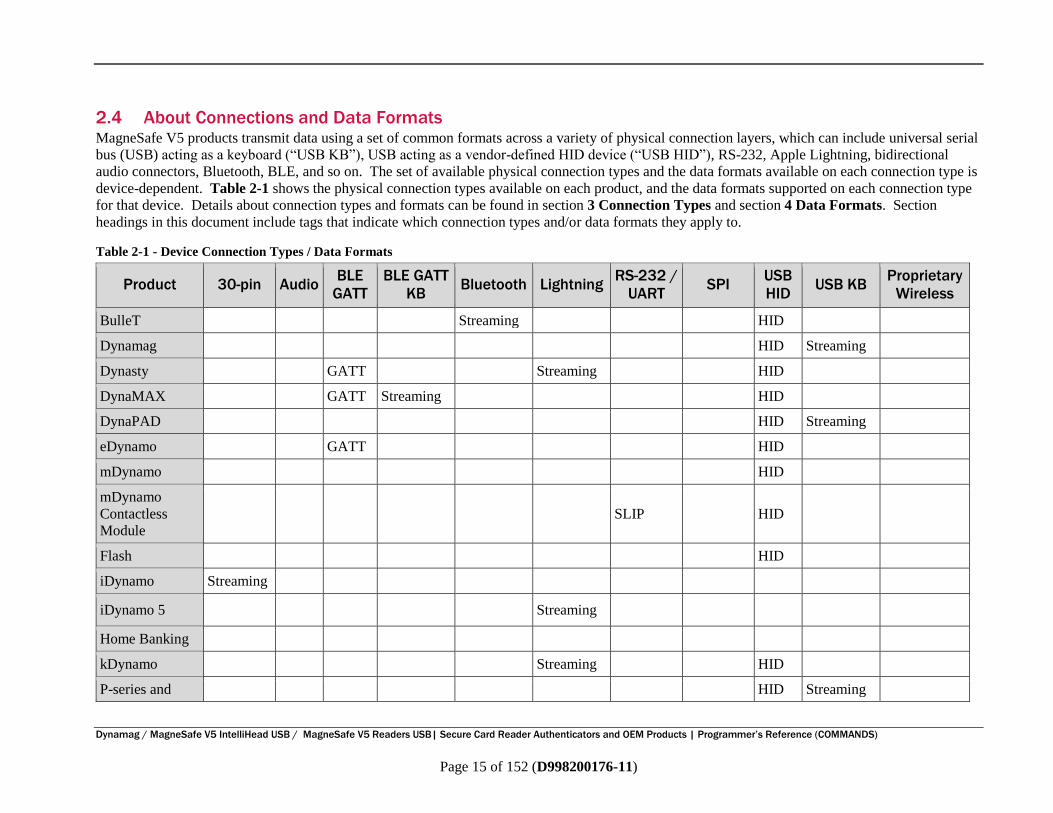
2.4 About Connections and Data Formats MagneSafe V5 products transmit data using a set of common formats across a variety of physical connection layers, which can include universal serial
bus (USB) acting as a keyboard (“USB KB”), USB acting as a vendor-defined HID device (“USB HID”), RS-232, Apple Lightning, bidirectional
audio connectors, Bluetooth, BLE, and so on. The set of available physical connection types and the data formats available on each connection type is
device-dependent. Table 2-1 shows the physical connection types available on each product, and the data formats supported on each connection type
for that device. Details about connection types and formats can be found in section 3 Connection Types and section 4 Data Formats. Section
headings in this document include tags that indicate which connection types and/or data formats they apply to.
Table 2-1 - Device Connection Types / Data Formats
Product 30-pin Audio BLE
GATT
BLE GATT
KB Bluetooth Lightning
RS-232 /
UART SPI
USB
HID USB KB
Proprietary
Wireless
BulleT Streaming HID
Dynamag HID Streaming
Dynasty GATT Streaming HID
DynaMAX GATT Streaming HID
DynaPAD HID Streaming
eDynamo GATT HID
mDynamo HID
mDynamo
Contactless
Module
SLIP HID
Flash HID
iDynamo Streaming
iDynamo 5 Streaming
Home Banking
kDynamo Streaming HID
P-series and HID Streaming

Dynamag / MagneSafe V5 IntelliHead USB / MagneSafe V5 Readers USB Secure Card Reader Authenticators and OEM Products
Programmer’s Reference (COMMANDS)
Dynamag / MagneSafe V5 IntelliHead USB / MagneSafe V5 Readers USB| Secure Card Reader Authenticators and OEM Products | Programmer’s Reference (COMMANDS)
Page 16 of 152 (D998200176-11)
Product 30-pin Audio BLE
GATT
BLE GATT
KB Bluetooth Lightning
RS-232 /
UART SPI
USB
HID USB KB
Proprietary
Wireless
I-65 w/V5
pDynamo GATT HID
SPI Enc
IntelliHead V5 Streaming
tDynamo GATT HID Streaming
UART Enc
IntelliHead V5 Streaming
USB Enc
IntelliHead V5 See Dynamag
uDynamo TLV HID
Dynamag / MagneSafe V5 IntelliHead USB / MagneSafe V5 Readers USB Secure Card Reader Authenticators and OEM Products
Programmer’s Reference (COMMANDS)
Dynamag / MagneSafe V5 IntelliHead USB / MagneSafe V5 Readers USB| Secure Card Reader Authenticators and OEM Products | Programmer’s Reference (COMMANDS)
Page 17 of 152 (D998200176-11)
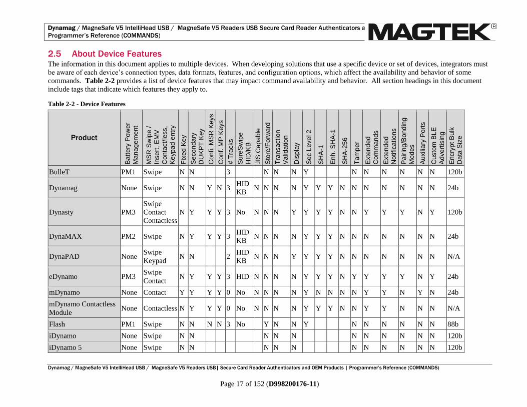
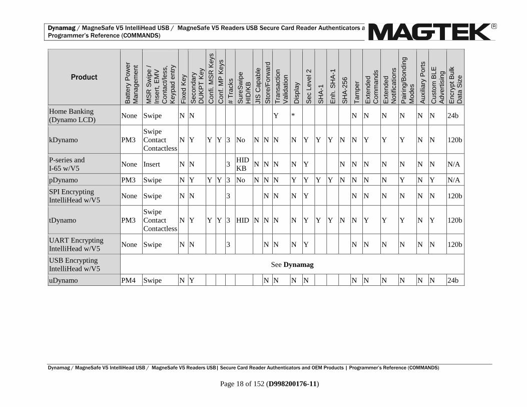
2.5 About Device Features The information in this document applies to multiple devices. When developing solutions that use a specific device or set of devices, integrators must
be aware of each device’s connection types, data formats, features, and configuration options, which affect the availability and behavior of some
commands. Table 2-2 provides a list of device features that may impact command availability and behavior. All section headings in this document
include tags that indicate which features they apply to.
Table 2-2 - Device Features
Product
Batt
ery
Pow
er
Mana
ge
ment
MS
R S
wip
e /
Insert
, E
MV
Conta
ct/
less,
Keypa
d e
ntr
y
Fix
ed K
ey
Secon
dary
DU
KP
T K
ey
Confi. M
SR
Keys
Conf. M
P K
eys
# T
racks
Sure
Sw
ipe
HID
/KB
JIS
Cap
ab
le
Sto
re/F
orw
ard
Tra
nsaction
Valid
ation
Dis
pla
y
Sec L
eve
l 2
SH
A-1
Enh.
SH
A-1
SH
A-2
56
Tam
per
Exte
nd
ed
Com
mands
Exte
nd
ed
Notifications
Pair
ing
/Bond
ing
Modes
Auxili
ary
Port
s
Custo
m B
LE
Advert
isin
g
Encry
pt B
ulk
Data
Siz
e
BulleT PM1 Swipe N N 3 N N N Y N N N N N N 120b
Dynamag None Swipe N N Y N 3 HID
KB N N N N Y Y Y N N N N N N N 24b
Dynasty PM3
Swipe
Contact
Contactless
N Y Y Y 3 No N N N Y Y Y Y N N Y Y Y N Y 120b
DynaMAX PM2 Swipe N Y Y Y 3 HID
KB N N N N Y Y Y N N N N N N N 24b
DynaPAD None Swipe
Keypad N N 2
HID
KB N N N Y Y Y Y N N N N N N N N/A
eDynamo PM3 Swipe
Contact N Y Y Y 3 HID N N N N Y Y Y N Y Y Y Y N Y 24b
mDynamo None Contact Y Y Y Y 0 No N N N N Y N N N N Y Y N Y N 24b
mDynamo Contactless
Module None Contactless N Y Y Y 0 No N N N N Y Y Y N N Y Y N N N N/A
Flash PM1 Swipe N N N N 3 No Y N N Y N N N N N N 88b
iDynamo None Swipe N N N N N N N N N N N 120b
iDynamo 5 None Swipe N N N N N N N N N N N 120b
Dynamag / MagneSafe V5 IntelliHead USB / MagneSafe V5 Readers USB Secure Card Reader Authenticators and OEM Products
Programmer’s Reference (COMMANDS)
Dynamag / MagneSafe V5 IntelliHead USB / MagneSafe V5 Readers USB| Secure Card Reader Authenticators and OEM Products | Programmer’s Reference (COMMANDS)
Page 18 of 152 (D998200176-11)
Product
Batt
ery
Pow
er
Mana
ge
ment
MS
R S
wip
e /
Insert
, E
MV
Conta
ct/
less,
Keypa
d e
ntr
y
Fix
ed K
ey
Secon
dary
DU
KP
T K
ey
Confi. M
SR
Keys
Conf. M
P K
eys
# T
racks
Sure
Sw
ipe
HID
/KB
JIS
Cap
ab
le
Sto
re/F
orw
ard
Tra
nsaction
Valid
ation
Dis
pla
y
Sec L
eve
l 2
SH
A-1
Enh.
SH
A-1
SH
A-2
56
Tam
per
Exte
nd
ed
Com
mands
Exte
nd
ed
Notifications
Pair
ing
/Bond
ing
Modes
Auxili
ary
Port
s
Custo
m B
LE
Advert
isin
g
Encry
pt B
ulk
Data
Siz
e
Home Banking
(Dynamo LCD) None Swipe N N Y * N N N N N N 24b
kDynamo PM3
Swipe
Contact
Contactless
N Y Y Y 3 No N N N N Y Y Y N N Y Y Y N N 120b
P-series and
I-65 w/V5 None Insert N N 3
HID
KB N N N N Y N N N N N N N N/A
pDynamo PM3 Swipe N Y Y Y 3 No N N N Y Y Y Y N N N N Y N Y N/A
SPI Encrypting
IntelliHead w/V5 None Swipe N N 3 N N N Y N N N N N N 120b
tDynamo PM3
Swipe
Contact
Contactless
N Y Y Y 3 HID N N N N Y Y Y N N Y Y Y N Y 120b
UART Encrypting
IntelliHead w/V5 None Swipe N N 3 N N N Y N N N N N N 120b
USB Encrypting
IntelliHead w/V5 See Dynamag
uDynamo PM4 Swipe N Y N N N N N N N N N N 24b

3 - Connection Types
Dynamag / MagneSafe V5 IntelliHead USB / MagneSafe V5 Readers USB| Secure Card Reader Authenticators and OEM Products |
Programmer’s Reference (COMMANDS)
Page 19 of 152 (D998200176-11)
3 Connection Types Table 2-1 on page 15 includes a list of connection types available for each device. The following
subsections provide details developers will need to communicate with the device using each connection
type.
3.1 How to Use USB Connections (USB, Proprietary Wireless) These USB devices conform to the USB specification revision 1.1. They also conform to the Human
Interface Device (HID) class specification version 1.1. This document assumes the reader is familiar with
USB HID class specifications, which are available at www.usb.org. MagTek strongly recommends
becoming familiar with that standard before trying to communicate with the device directly via USB.
When connecting via USB, MagneSafe V5 devices connect to the USB host either as a vendor-defined
HID device (“HID”) or as an HID Keyboard Emulation device (“KB”), depending on the device type and
configuration. Details for using the device in each of these modes are provided in the sections that
follow. In addition to connecting to the USB host as different USB device types depending on their
mode, the device can transmit data in different formats (see section 4 Data Formats). To decode
incoming device data for devices connected as HID devices, see section 4.1 How to Use HID Format
(HID). To decode incoming device data for devices connected as KB devices, see section 4.2 How to
Use Streaming Format (Streaming).
These devices are full-speed, high-powered USB devices that draw power from the USB bus they are
connected to. They enter and wake up from Suspend mode when directed to do so by the USB host.
They do not support remote wakeup.
The devices have an adjustable endpoint descriptor polling interval value that can be set to any value in
the range of 1ms to 255ms. This property can be used to speed up or slow down the card data transfer
rate [see section 9.3 Property 0x02 - USB Polling Interval (HID, KB)].
MagneSafe V5 devices identify themselves with MagTek’s vendor ID, 0x0801. They report their Product
ID (PID) according to the following rules:
Swipe devices report PID 0x0011 when in HID mode.
Insert devices report PID 0x0013 when in HID mode.
Audio devices report PID 0x0017 when in HID mode.
Combination EMV/swipe devices report PID 0x0019 when in HID mode.
All devices report PID 0x0001 when in KB mode.
Wireless USB device dongles report PID 0x0011 when in HID mode.
Wireless USB device dongles report PID 0x0001 when in KB mode.
Wireless USB devices report PID 0x0014 when plugged directly into the host with a USB cable.
3 - Connection Types
Dynamag / MagneSafe V5 IntelliHead USB / MagneSafe V5 Readers USB| Secure Card Reader Authenticators and OEM Products |
Programmer’s Reference (COMMANDS)
Page 20 of 152 (D998200176-11)
3.1.1 About USB Reports, Usages, Usage Pages, and Usage IDs
All USB HID devices send and receive data using reports. Each report can contain several sections,
called usages, each of which has its own unique four-byte (32-bit) identifier. The two most significant
bytes of a usage are called the usage page, and the two least significant bytes are called the usage ID.
Vendor-defined usages must have a usage page in the range 0xFF00 - 0xFFFF, and it is common practice
for related usage IDs share the same usage page. For these reasons, all usages for MagneSafe V5 devices
use vendor-defined usage page 0xFF00, Magnetic Stripe Reader.
HID reports used by the host can be divided into two types:
Feature Reports, which the host uses to send data to the device. Feature reports can be divided into
Get types and Set types. MagneSafe V5 devices only use one feature report.
Input Reports are used by the device to send asynchronous responses or notifications to the host
when a related feature report completes, or automatically when the device’s state changes. The
device commonly uses this asynchronous notification when a command depends on cardholder action
or otherwise takes more time to run. For details about input reports, see section 3.1.3 How to
Receive Data On the USB Connection (HID).
Host software should use the HID class-specific request Set Report to send Set type Feature Reports to
the device as commands, and use the HID class-specific request Get Report to send Get type Feature
Reports to retrieve data or responses from the device when synchronous response is appropriate.
Both request types are sent over the default control pipe, and the device will NAK the Status page of the
Set Report request until the command is completed. This ensures that as soon as the Set Report request
is completed, the host can call a follow-up Get Report request to get the command response.
Details about using Feature Reports can be found in section 3.1.2 How to Send Commands On the USB
Connection. Details about using input reports are provided in section 3.1.3 How to Receive Data On
the USB Connection (HID).
3 - Connection Types
Dynamag / MagneSafe V5 IntelliHead USB / MagneSafe V5 Readers USB| Secure Card Reader Authenticators and OEM Products |
Programmer’s Reference (COMMANDS)
Page 21 of 152 (D998200176-11)
3.1.2 How to Send Commands On the USB Connection
When the device is connected to the host via USB, regardless of whether the device identifies and
operates as a vendor-defined HID device or as a keyboard, the host uses the Set and Get forms of feature
report 0x20 to send commands to the device and receive responses.
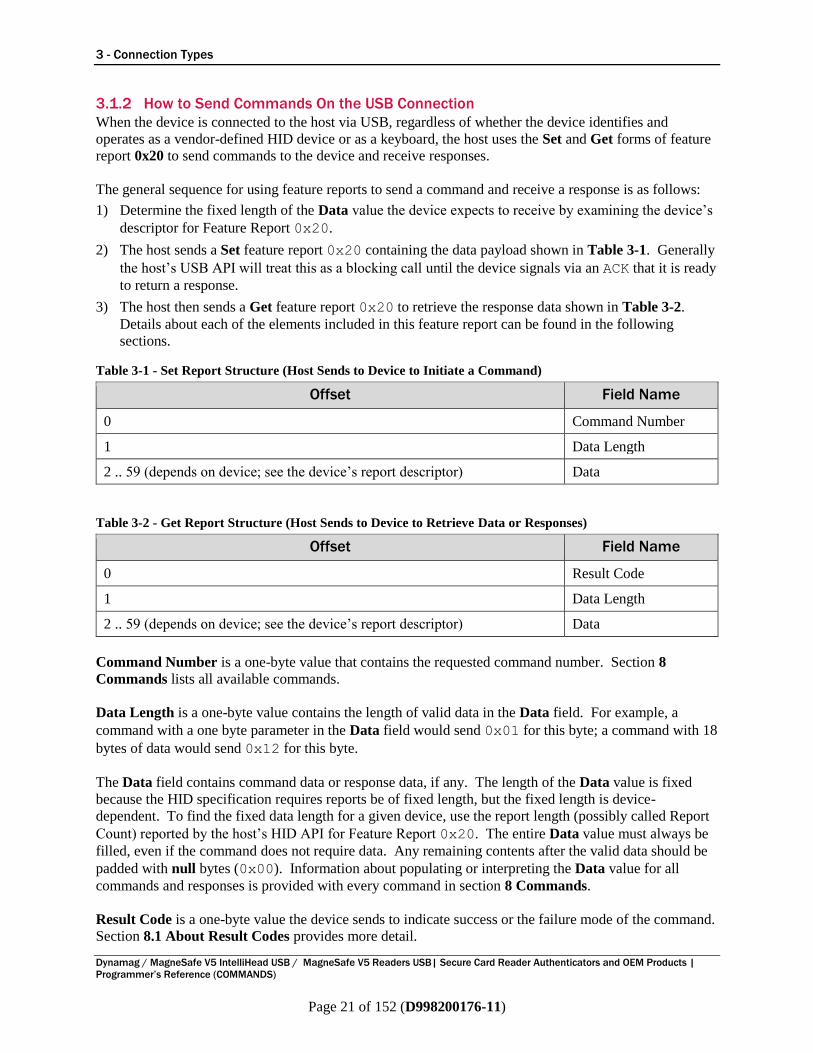
The general sequence for using feature reports to send a command and receive a response is as follows:
1) Determine the fixed length of the Data value the device expects to receive by examining the device’s
descriptor for Feature Report 0x20.
2) The host sends a Set feature report 0x20 containing the data payload shown in Table 3-1. Generally
the host’s USB API will treat this as a blocking call until the device signals via an ACK that it is ready
to return a response.
3) The host then sends a Get feature report 0x20 to retrieve the response data shown in Table 3-2.
Details about each of the elements included in this feature report can be found in the following
sections.
Table 3-1 - Set Report Structure (Host Sends to Device to Initiate a Command)
Offset Field Name
0 Command Number
1 Data Length
2 .. 59 (depends on device; see the device’s report descriptor) Data
Table 3-2 - Get Report Structure (Host Sends to Device to Retrieve Data or Responses)
Offset Field Name
0 Result Code
1 Data Length
2 .. 59 (depends on device; see the device’s report descriptor) Data
Command Number is a one-byte value that contains the requested command number. Section 8
Commands lists all available commands.
Data Length is a one-byte value contains the length of valid data in the Data field. For example, a
command with a one byte parameter in the Data field would send 0x01 for this byte; a command with 18
bytes of data would send 0x12 for this byte.
The Data field contains command data or response data, if any. The length of the Data value is fixed
because the HID specification requires reports be of fixed length, but the fixed length is device-
dependent. To find the fixed data length for a given device, use the report length (possibly called Report
Count) reported by the host’s HID API for Feature Report 0x20. The entire Data value must always be
filled, even if the command does not require data. Any remaining contents after the valid data should be
padded with null bytes (0x00). Information about populating or interpreting the Data value for all
commands and responses is provided with every command in section 8 Commands.
Result Code is a one-byte value the device sends to indicate success or the failure mode of the command.
Section 8.1 About Result Codes provides more detail.

3 - Connection Types
Dynamag / MagneSafe V5 IntelliHead USB / MagneSafe V5 Readers USB| Secure Card Reader Authenticators and OEM Products |
Programmer’s Reference (COMMANDS)
Page 22 of 152 (D998200176-11)
3 - Connection Types
Dynamag / MagneSafe V5 IntelliHead USB / MagneSafe V5 Readers USB| Secure Card Reader Authenticators and OEM Products |
Programmer’s Reference (COMMANDS)
Page 23 of 152 (D998200176-11)
3.1.3 How to Receive Data On the USB Connection (HID)
When the device communicates with the host as a vendor-defined HID device, it sends unsolicited
messages such as card data to the host via one or more Input Reports, which are asynchronous data
packets (i.e., events) sent from the device to the host using the USB Interrupt IN pipe. Events occur
when the device state changes or when an asynchronous command (such as a command that requires
cardholder interaction) has completed.
Devices that do not support Notifications (a specific way of sending asynchronous data to the host, see
section 2.5 About Device Features) implement a single input report for Magnetic Stripe Card Data
Sent from Device to Host (Swipe or Keypad Entry Only). Because these devices only implement one
input report, the input report they send to the host does not include a report identifier, in accordance with
the USB HID specification. The host can locate a specific data element in the input report by finding the
corresponding Usage and interpreting its contents as binary data. For example, upon receiving an input
report, the host software can find Track 1 Decode Status (HID, TLV, GATT) as follows:
1) Knowing from section 3.1.1 that the device uses usage page 0xFF00, and knowing from the “Where
to Find Value” column in the first table of section 7.2 that the desired data is found in the usage with
Usage ID 0x0020, call the platform’s USB SDK to retrieve the data from usage 0xFF000020 in
the input report.
2) Interpret the single binary data byte from that Usage according to the second table in section 7.2.
Per the USB HID standard, the host polls the device on a regular Polling Interval to see if it has input data
available to send. If the device does not, it will respond to the poll with a USB NAK.
3 - Connection Types
Dynamag / MagneSafe V5 IntelliHead USB / MagneSafe V5 Readers USB| Secure Card Reader Authenticators and OEM Products |
Programmer’s Reference (COMMANDS)
Page 24 of 152 (D998200176-11)
3.1.4 How to Use the USB Connection in Keyboard Emulation Mode (KB)
When the device is set to Security Level 2, the factory default setting is for the device to transmit data in
SureSwipe format, and this section does not apply. See D99875206 Technical Reference Manual,
USB KB SureSwipe & Swipe Reader instead.
When the device is operating in USB keyboard emulation (“KB”) mode (see Property 0x10 - Interface
Type], it expects to receive commands and send command responses using HID format (see section 3.1.2
How to Send Commands On the USB Connection), and sends Magnetic Stripe Card Data Sent from
Device to Host (Swipe or Keypad Entry Only) using Streaming format [see section 4.2.1 Magnetic
Stripe Card Data In Streaming Format)] as follows:
A device in KB mode identifies itself to the USB host as a keyboard, and transmits streaming data to the
host as ASCII as though it is being typed by a person on an actual keyboard. It does this by mapping each
of the possible ASCII characters in the stream to keystrokes. By default, to send an ASCII character to
the host, the device looks up the ASCII character in the key map [see Property 0x16 - Active Keymap
(KB, MSR Only)] and retrieves a combination of a single Key Usage ID (defined in Appendix B
Keyboard Usage ID Definitions), which is a unique value assigned to every keyboard key, and a Key
Modifier Byte (defined in appendix B.2 Modifier Byte Definitions), and sends them to the host. The
key modifier byte modifies the meaning of the key usage ID, by indicating whether any combination of
the right or left Ctrl , Shift , Alt or GUI keys [as defined by Universal Serial Bus (USB) Device Class
Definition for Human Interface Devices (HID)] are pressed at the same time as the key usage ID.
The device transmits ASCII 0 to 31 and 127 as their equivalent control code combinations. For example,
for a carriage return value 13 (0x0D), the device will appear to the host as a keyboard where a person
very quickly presses and holds the Ctrl key, then presses the M key, then releases both keys.
When the keymap contains a Key Usage ID and Key Modifier Byte of 0xFF for the ASCII value the
device wants to send, or if Property 0x17 - ASCII to Keypress Conversion Type (KB, MSR Only) is
set to Alt ASCII Code, the device uses Alt ASCII code keystrokes instead of key map values, meaning it
simulates holding down the Alt key on a keyboard and typing the three-digit decimal value of the ASCII
character it wants to send. For example, to transmit the ASCII character ‘?’ (063 decimal in the ASCII
table), the device sends keypad ‘0’ combined with the Left Alt key modifier, then keypad ‘6’ combined
with the Left Alt key modifier, then keypad ‘3’ combined with the Left Alt key modifier.
Caution
Because the host perceives a KB mode device as a keyboard, pressing keys on another
keyboard connected to the host while the device is transmitting may corrupt the data the
host receives.

4 - Data Formats
Dynamag / MagneSafe V5 IntelliHead USB / MagneSafe V5 Readers USB| Secure Card Reader Authenticators and OEM Products |
Programmer’s Reference (COMMANDS)
Page 25 of 152 (D998200176-11)
4 Data Formats
4.1 How to Use HID Format (HID) When the device and host are communicating in vendor-defined HID mode, data comes from the device
as described in section 3.1.3 How to Receive Data On the USB Connection (HID). The host software
can retrieve the incoming data by examining the various usages in the report(s). For details about which
usages to examine and how to interpret the data, see section 7 Magnetic Stripe Card Data Sent from
Device to Host.
4 - Data Formats
Dynamag / MagneSafe V5 IntelliHead USB / MagneSafe V5 Readers USB| Secure Card Reader Authenticators and OEM Products |
Programmer’s Reference (COMMANDS)
Page 26 of 152 (D998200176-11)
4.2 How to Use Streaming Format (Streaming) This section describes how the device functions when it is using Streaming format on its current
connection to the host. Some device connection types use streaming format for both
commands/responses and for magnetic stripe data, while other device connection types use streaming
format just for magnetic stripe data. The following sections describe each of these separately.
4.2.1 Magnetic Stripe Card Data In Streaming Format (Swipe or Keypad Entry)
In streaming format, the device sends Magnetic Stripe Card Data Sent from Device to Host (Swipe or
Keypad Entry Only) as a series of potentially variable length fields in a fixed order, separated by
delimiters. Many of the delimiters are configurable, which allows the device to output customized
sequences of characters to the host. These options are most commonly used when the device
communicates with the host as if the device were a keyboard [see section 3.1.4 How to Use the USB
Connection in Keyboard Emulation Mode (KB)], where developers may configure the delimiters to
drive the host’s user interface to advance from one user interface field to the next, or to submit a filled out
form.
Streaming data is composed entirely of ASCII characters, but the host should interpret the characters
differently depending on the nature of the data:
ASCII fields like Masked Track Data, Device Serial Number, and Format Code (Streaming)
simply contain the data as ASCII characters.
Binary fields like Device Encryption Status, Encrypted Track Data, MagnePrint Status,
Encrypted MagnePrint Data, Encrypted Session ID, DUKPT Key Serial Number, Clear Text
CRC (Streaming), and Encrypted CRC (Streaming) are hexadecimal encoded, where the contents
consist only of the characters 0123456789ABCDEF, and every two bytes represents the hexadecimal
value of the binary byte being sent. The host should decode every two characters as one byte.
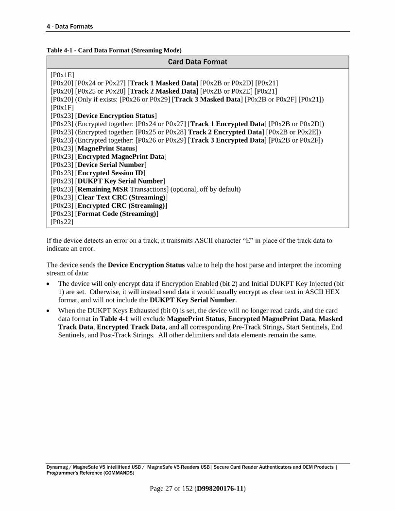
The delimiters the device sends between fields are stored as Properties in the device’s non-volatile
memory, which the host can configure using Command 0x01 - Set Property (MAC). Table 4-1 shows
the format the device uses to transmit magnetic stripe data in Streaming mode, where the delimiter
properties are abbreviated as a “P” followed by the property number. When transmitting card data to the
host, the device replaces each bracketed [P0x##] value with the actual value contained in the specified
property, and replaces other bracketed values with card data. For information about a specific property’s
valid values and effects on device behavior, see its documentation in section 9 Properties.
4 - Data Formats
Dynamag / MagneSafe V5 IntelliHead USB / MagneSafe V5 Readers USB| Secure Card Reader Authenticators and OEM Products |
Programmer’s Reference (COMMANDS)
Page 27 of 152 (D998200176-11)
Table 4-1 - Card Data Format (Streaming Mode)
Card Data Format
[P0x1E]
[P0x20] [P0x24 or P0x27] [Track 1 Masked Data] [P0x2B or P0x2D] [P0x21]
[P0x20] [P0x25 or P0x28] [Track 2 Masked Data] [P0x2B or P0x2E] [P0x21]
[P0x20] (Only if exists: [P0x26 or P0x29] [Track 3 Masked Data] [P0x2B or P0x2F] [P0x21])
[P0x1F]
[P0x23] [Device Encryption Status]
[P0x23] (Encrypted together: [P0x24 or P0x27] [Track 1 Encrypted Data] [P0x2B or P0x2D])
[P0x23] (Encrypted together: [P0x25 or P0x28] Track 2 Encrypted Data] [P0x2B or P0x2E])
[P0x23] (Encrypted together: [P0x26 or P0x29] [Track 3 Encrypted Data] [P0x2B or P0x2F])
[P0x23] [MagnePrint Status]
[P0x23] [Encrypted MagnePrint Data]
[P0x23] [Device Serial Number]
[P0x23] [Encrypted Session ID]
[P0x23] [DUKPT Key Serial Number]
[P0x23] [Remaining MSR Transactions] (optional, off by default)
[P0x23] [Clear Text CRC (Streaming)]
[P0x23] [Encrypted CRC (Streaming)]
[P0x23] [Format Code (Streaming)]
[P0x22]
If the device detects an error on a track, it transmits ASCII character “E” in place of the track data to
indicate an error.
The device sends the Device Encryption Status value to help the host parse and interpret the incoming
stream of data:
The device will only encrypt data if Encryption Enabled (bit 2) and Initial DUKPT Key Injected (bit
1) are set. Otherwise, it will instead send data it would usually encrypt as clear text in ASCII HEX
format, and will not include the DUKPT Key Serial Number.
When the DUKPT Keys Exhausted (bit 0) is set, the device will no longer read cards, and the card
data format in Table 4-1 will exclude MagnePrint Status, Encrypted MagnePrint Data, Masked
Track Data, Encrypted Track Data, and all corresponding Pre-Track Strings, Start Sentinels, End
Sentinels, and Post-Track Strings. All other delimiters and data elements remain the same.
4 - Data Formats
Dynamag / MagneSafe V5 IntelliHead USB / MagneSafe V5 Readers USB| Secure Card Reader Authenticators and OEM Products |
Programmer’s Reference (COMMANDS)
Page 28 of 152 (D998200176-11)
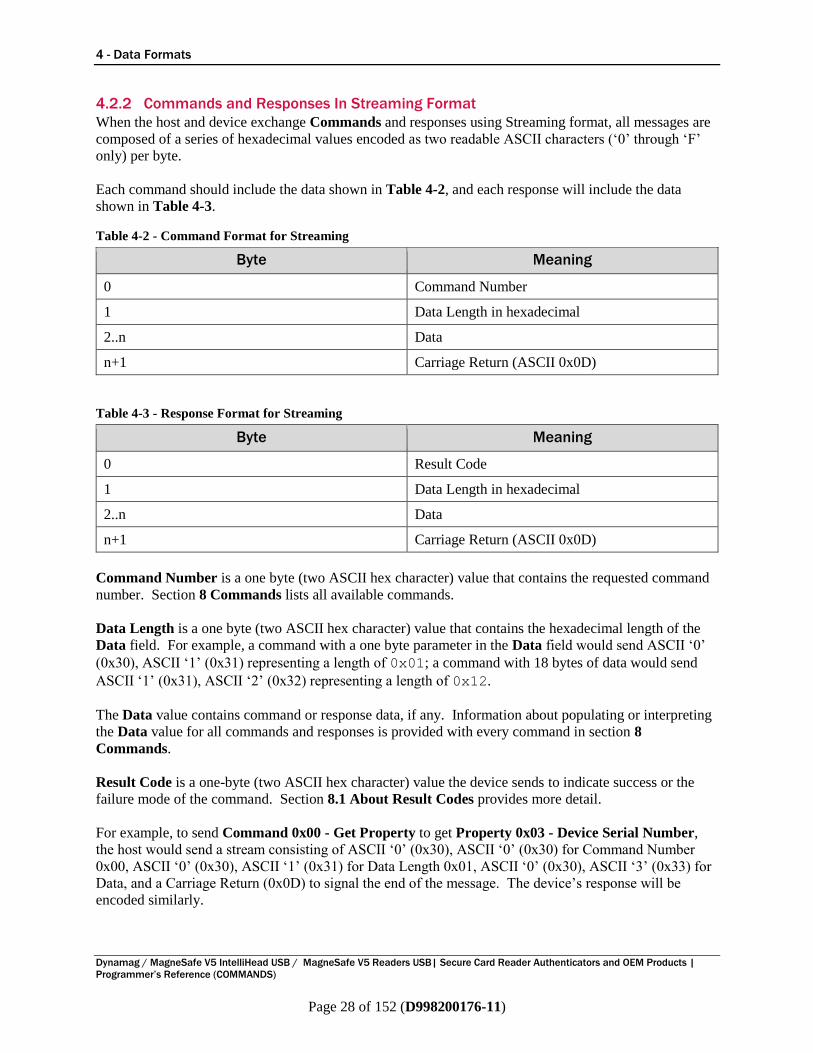
4.2.2 Commands and Responses In Streaming Format
When the host and device exchange Commands and responses using Streaming format, all messages are
composed of a series of hexadecimal values encoded as two readable ASCII characters (‘0’ through ‘F’
only) per byte.
Each command should include the data shown in Table 4-2, and each response will include the data
shown in Table 4-3.
Table 4-2 - Command Format for Streaming
Byte Meaning
0 Command Number
1 Data Length in hexadecimal
2..n Data
n+1 Carriage Return (ASCII 0x0D)
Table 4-3 - Response Format for Streaming
Byte Meaning
0 Result Code
1 Data Length in hexadecimal
2..n Data
n+1 Carriage Return (ASCII 0x0D)
Command Number is a one byte (two ASCII hex character) value that contains the requested command
number. Section 8 Commands lists all available commands.
Data Length is a one byte (two ASCII hex character) value that contains the hexadecimal length of the
Data field. For example, a command with a one byte parameter in the Data field would send ASCII ‘0’
(0x30), ASCII ‘1’ (0x31) representing a length of 0x01; a command with 18 bytes of data would send
ASCII ‘1’ (0x31), ASCII ‘2’ (0x32) representing a length of 0x12.
The Data value contains command or response data, if any. Information about populating or interpreting
the Data value for all commands and responses is provided with every command in section 8
Commands.
Result Code is a one-byte (two ASCII hex character) value the device sends to indicate success or the
failure mode of the command. Section 8.1 About Result Codes provides more detail.
For example, to send Command 0x00 - Get Property to get Property 0x03 - Device Serial Number,
the host would send a stream consisting of ASCII ‘0’ (0x30), ASCII ‘0’ (0x30) for Command Number
0x00, ASCII ‘0’ (0x30), ASCII ‘1’ (0x31) for Data Length 0x01, ASCII ‘0’ (0x30), ASCII ‘3’ (0x33) for
Data, and a Carriage Return (0x0D) to signal the end of the message. The device’s response will be
encoded similarly.

5 - Security Levels
Dynamag / MagneSafe V5 IntelliHead USB / MagneSafe V5 Readers USB| Secure Card Reader Authenticators and OEM Products |
Programmer’s Reference (COMMANDS)
Page 29 of 152 (D998200176-11)
5 Security Levels Devices can be configured to operate at different Security Levels, which affects the content sent from the
device to the host when a card is swiped, the host software’s ability to modify properties, and the host
software’s ability to execute certain commands. This section provides details about how the different
security levels affect the device’s behavior.
Most MagneSafe devices support three Security Levels: Level 2, Level 3, and Level 4. The Security
Level can be increased by sending commands to the device, but can never be decreased.
5.1 About Message Authentication Codes (MAC) Commands in this manual that are tagged “MAC” are privileged commands. If the device is set to a
Security Level higher than 2 (see section 5 Security Levels), the host software must calculate and append
a four-byte Message Authentication Code (“MAC”) to the Data field of the message, extending the length
of the field by 4 bytes, to prove the sender is authorized to execute that command. The host software
should calculate the MAC per ISO 9797-1, MAC Algorithm 3, Padding Method 1. Data supplied to the
MAC algorithm should be provided in raw binary form, not converted to ASCII-hexadecimal. The MAC
key to be used is as specified in ANSI X9.24 Part 1, Appendix A (“Request PIN Entry 2” bullet 2). The
host should use the current DUKPT KSN (which can be retrieved using Command 0x09 - Get Current
TDES DUKPT KSN) to get a reference to the MAC key.
Upon successfully completing any MACed command, the device advances the DUKPT Key.
If a MAC is required but not present or incorrect, the device will return 0x07.
5.2 Security Level 2 Security Level 2 is the least secure mode. In this mode, keys are loaded but the device does not require
the host software to use them for most operations: Keys are used/needed to load new keys and to move to
Security Level 3 or 4, but all other properties and commands are freely usable. The host can use
Command 0x15 - Get / Set Security Level (MAC) to determine the device’s current security level.
(MSR Only:)
In Security Level 2, if the device is using Streaming format (see section 4.2 How to Use Streaming
Format), the device sends data in the SureSwipe format (see MagTek document D99875206 Technical
Reference Manual, USB KB SureSwipe & Swipe Reader). The default SureSwipe mode can be
changed to allow the device to send data in the MagneSafe V5 format described in this manual, but the
device will not send MagnePrint data.
In Security Level 2, if the device is using HID format, the device sends track data but does not send
MagnePrint data. By default, the data is sent in the format defined in this manual. Changing Property
0x38 - HID SureSwipe Flag (HID, MSR Only) to 0x01 will cause the device to use the SureSwipe
VID/PID and send data as defined in D99875191 Technical Reference Manual, USB HID SureSwipe
& Swipe Reader.
5.3 Security Level 3 Security Level 3 enables encryption of track data, MagnePrint data, and the Session ID. MagnePrint data
is always included and always encrypted. The host can use Command 0x15 - Get / Set Security Level
(MAC) to determine the device’s current security level.
5 - Security Levels
Dynamag / MagneSafe V5 IntelliHead USB / MagneSafe V5 Readers USB| Secure Card Reader Authenticators and OEM Products |
Programmer’s Reference (COMMANDS)
Page 30 of 152 (D998200176-11)
5.4 Security Level 4 (MSR Only) When the device is at Security Level 4, the device requires the host to successfully complete an
Authentication Sequence before it will transmit data from a card swipe (see section 8.2.9 Command 0x10
- Activate Authenticated Mode). Correctly executing the Authentication Sequence also causes the green
LED to blink, alerting the operator that the device is being controlled by a host with knowledge of the
keys—that is, an Authentic Host. The host can use Command 0x15 - Get / Set Security Level (MAC)
to determine the device’s current security level.
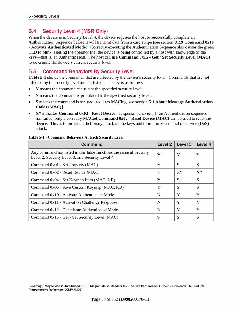
5.5 Command Behaviors By Security Level Table 5-1 shows the commands that are affected by the device’s security level. Commands that are not
affected by the security level are not listed. The key is as follows:
Y means the command can run at the specified security level.
N means the command is prohibited at the specified security level.
S means the command is secured [requires MACing, see section 5.1 About Message Authentication
Codes (MAC)].
X* indicates Command 0x02 - Reset Device has special behavior. If an Authentication sequence
has failed, only a correctly MACed Command 0x02 - Reset Device (MAC) can be used to reset the
device. This is to prevent a dictionary attack on the keys and to minimize a denial of service (DoS)
attack.
Table 5-1 - Command Behaviors At Each Security Level
Command Level 2 Level 3 Level 4
Any command not listed in this table functions the same at Security
Level 2, Security Level 3, and Security Level 4. Y Y Y
Command 0x01 - Set Property (MAC) Y S S
Command 0x02 - Reset Device (MAC) Y X* X*
Command 0x04 - Set Keymap Item (MAC, KB) Y S S
Command 0x05 - Save Custom Keymap (MAC, KB) Y S S
Command 0x10 - Activate Authenticated Mode N Y Y
Command 0x11 - Activation Challenge Response N Y Y
Command 0x12 - Deactivate Authenticated Mode N Y Y
Command 0x15 - Get / Set Security Level (MAC) S S S
6 - Encryption, Decryption, and Key Management
Dynamag / MagneSafe V5 IntelliHead USB / MagneSafe V5 Readers USB| Secure Card Reader Authenticators and OEM Products |
Programmer’s Reference (COMMANDS)
Page 31 of 152 (D998200176-11)
6 Encryption, Decryption, and Key Management Some data exchanged between the device and the host is encrypted. This includes Encrypted Track
Data, Encrypted MagnePrint Data, Encrypted Session ID, Encrypted CRC (Streaming). To decrypt
it, the host must first determine what key to use, then decrypt the data.
6.1 Determining Key When the device and the host are using TDES DUKPT key management and the device is encrypting data
(see Security Levels), the host software must do the following to generate a key (the “derived key”) to
use for decryption:
1) Determine the value of the Initial Key loaded into the device. The lookup methods the host
software uses will depend on the overall solution architecture and are outside the scope of this
document. However, most solutions will do this in one of two ways, both of which use the Initial
Key Serial Number that arrives with the encrypted data (see Command 0x09 - Get Current TDES
DUKPT KSN for details about interpreting the KSN):
a) Look up the value of the Base Derivation Key using the Initial KSN portion of the current KSN
as an index value, then use TDES DUKPT algorithms to calculate the value of the Initial Key; or
b) Look up the value of the Initial Key directly, using the Initial KSN portion of the current KSN as
an index value.
2) Derive the current key. Apply TDES DUKPT algorithms to the Initial Key value and the encryption
counter portion of the KSN that arrives with the encrypted data.
3) Determine what “variant” the device used to create the derived key it used to encrypt. The
variants are defined in ANS X9.24 Part 1, which programmers of host software must be familiar
with. Which variant the host should use to calculate the derived key depends on the type of data the
host is decrypting or encrypting, and on device settings:
a) Encrypted CRC (Streaming) data will always be encrypted using the Message Authentication,
request or both ways variant.
b) Encrypted MagnePrint Data will be encrypted according to the setting in Property 0x54 -
Card Data Encryption Variant (MSR Only, Configurable MSR Keys Only), if the device
supports it. Otherwise, it will be encrypted using the PIN Encryption variant.
c) Encrypted Track Data and Encrypted Session ID will be encrypted according to the setting in
Property 0x54 - Card Data Encryption Variant (MSR Only, Configurable MSR Keys Only),
if the device supports it. Otherwise, it will be encrypted using the PIN Encryption variant.
4) Use the variant algorithm with the current key to calculate that variant.
5) Decrypt the data according to the steps in section 6.2 Decrypting Data.
6 - Encryption, Decryption, and Key Management
Dynamag / MagneSafe V5 IntelliHead USB / MagneSafe V5 Readers USB| Secure Card Reader Authenticators and OEM Products |
Programmer’s Reference (COMMANDS)
Page 32 of 152 (D998200176-11)
6.2 Decrypting Data For Encrypted Track Data the device begins by encrypting the first 8 bytes of clear text track data. The
8-byte result of this encryption is placed in an encrypted data buffer. The process continues using the
DES CBC (Cipher Block Chaining) method with the encrypted 8 bytes XORed with the next 8 bytes of
clear text. That result is placed in next 8 bytes of the encrypted data buffer, and the device continues until
all clear text bytes have been encrypted. If the final block of clear text contains fewer than 8 bytes, the
device pads the end of the block to make 8 bytes. After the final clear text block is XORed with the prior
8 bytes of encrypted data, the device encrypts it and places it in the encrypted data value. No Initial
Vector is used in the process.
The host must decrypt the data in 8 byte blocks, ignoring any final unused bytes in the last block. When a
value consists of more than one block, the host should use the CBC method to decrypt the data by
following these steps:
1) Start decryption on the last block of 8 bytes (call it block N) using the key.
2) XOR the result of the decryption with the next-last block of 8 bytes (block N-1).
3) Repeat until reaching the first block.
4) Do not XOR the first block with anything.
5) Concatenate all blocks.
6) Determine the expected length of the decrypted data. In some cases this may be a standard field
length, and in other cases the expected data length may accompany the encrypted data. When
decrypting track data where no length is available, the host software can use the End Sentinel to find
the actual end of the data (ignoring the padding at the end, which will be all zeroes).
7) Truncate the end of the decrypted data block to the expected data length, which discards the padding
at the end.
7 - Magnetic Stripe Card Data Sent from Device to Host (Swipe or Keypad Entry Only)
Dynamag / MagneSafe V5 IntelliHead USB / MagneSafe V5 Readers USB| Secure Card Reader Authenticators and OEM Products |
Programmer’s Reference (COMMANDS)
Page 33 of 152 (D998200176-11)
7 Magnetic Stripe Card Data Sent from Device to Host (Swipe or
Keypad Entry Only) The device sends card swipe data to the host even if it can not fully decode the data. How the host
interprets incoming messages to find the data detailed in this section will depend on the connection type
(see section 3 Connection Types) and the data format (see section 4 Data Formats). Each subsection is
tagged with the features, connection types, and data formats for which it is relevant.
7.1 About Track Data After the host receives and decrypts Encrypted Track Data, or receives clear text track data (based on
device settings or state), or receives Masked Track Data, it may need to parse each track into individual
values embedded in the tracks. The device can read multiple card formats, which vary even between
different issuers and payment brands using the same underlying standards. Describing all possible
formats is beyond the scope of this document, but this section describes how to parse data from tracks 1,
2, and 3 in a generic ISO/ABA compliant format as an example.
Table 7-1 shows an example of ISO/ABA track data the device sends to the host, using unmasked
placeholder numbers to make it easier to see the relative positions of the values embedded in the track
data. It is important to note that some cards will not include Track 3 data, and some devices will not read
or transmit Track 3 data (see section 2.5 About Device Features). On devices that have a keypad,
manually entered data does not include Track 3.
Table 7-1 – Example Generic ISO/ABA Track Data Format
Generic ISO/ABA Track Data Format
Track 1 Data %75555555555555555^CARDHOLDER NAME/^33338880004444000006?
Track 2 Data ;5555555555555555=33338880004444006?
Track 3 Data ;5555555555555555=333388800044440000006?
The example track data in Table 7-1 can be interpreted as follows:
The % , ? , and ; are Sentinels / delimiters, and are taken directly from the data on the card, except
when using Streaming format, where they may be overridden by Properties as described in section
4.2.1 Magnetic Stripe Card Data In Streaming Format (Swipe or Keypad Entry). On devices
that have a keypad, manually entered data in Streaming format (and only in Streaming format) will
also construct track data using those Properties as delimiters.
The 7 at the beginning of Track 1 data is the card format code. For swiped credit / debit cards, this
will come from the card and will generally be B . On devices that have a keypad, manually entered
data will use M .
The string of 5s is the Account Number / License Number / PAN.
The carets ^ are a standard ISO track 1 delimiter surrounding the Cardholder Name.
CARDHOLDER NAME/ is the Cardholder Name. On devices that have a keypad, manually entered
data will use string literal MANUAL ENTRY/ .
The string of 3s is the Expiration Date.
The string of 8s is the Service Code. For swiped credit / debit cards, this will come from the card.
On devices that have a keypad, manually entered data will use 000 .
The remaining characters (0s, 4s, and 6 ) are Discretionary Data. For swiped debit / credit cards this
data will be of varying length and content and will come from the card, and must be interpreted
7 - Magnetic Stripe Card Data Sent from Device to Host (Swipe or Keypad Entry Only)
Dynamag / MagneSafe V5 IntelliHead USB / MagneSafe V5 Readers USB| Secure Card Reader Authenticators and OEM Products |
Programmer’s Reference (COMMANDS)
Page 34 of 152 (D998200176-11)
according to the standards established by issuers, payment brands, and so on. On devices that have a
keypad, manually entered track data will use a MagTek standard for Discretionary Data as follows:
o The string of 4s is the CVV2 a cardholder or operator entered on the keypad. This may be 3
or 4 characters long and is not padded, so the host software must find it by using the fixed-
length padding and sentinels that surround it.
o The strings of 0s are literals of fixed length: Track 1 will have three zeroes after the Service
Code, and five zeroes after the CVV2; Track 2 will have three zeroes after the Service Code,
and two zeroes after CVV2.
o The 6 will contain either a 0 or a 1.
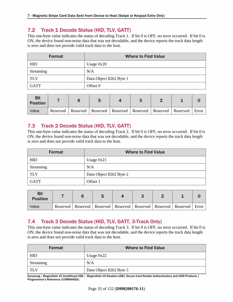
7 - Magnetic Stripe Card Data Sent from Device to Host (Swipe or Keypad Entry Only)
Dynamag / MagneSafe V5 IntelliHead USB / MagneSafe V5 Readers USB| Secure Card Reader Authenticators and OEM Products |
Programmer’s Reference (COMMANDS)
Page 35 of 152 (D998200176-11)
7.2 Track 1 Decode Status (HID, TLV, GATT) This one-byte value indicates the status of decoding Track 1. If bit 0 is OFF, no error occurred. If bit 0 is
ON, the device found non-noise data that was not decodable, and the device reports the track data length
is zero and does not provide valid track data to the host.
Format Where to Find Value
HID Usage 0x20
Streaming N/A
TLV Data Object 8262 Byte 1
GATT Offset 0
Bit
Position 7 6 5 4 3 2 1 0
Value Reserved Reserved Reserved Reserved Reserved Reserved Reserved Error
7.3 Track 2 Decode Status (HID, TLV, GATT) This one-byte value indicates the status of decoding Track 2. If bit 0 is OFF, no error occurred. If bit 0 is
ON, the device found non-noise data that was not decodable, and the device reports the track data length
is zero and does not provide valid track data to the host.
Format Where to Find Value
HID Usage 0x21
Streaming N/A
TLV Data Object 8262 Byte 2
GATT Offset 1
Bit
Position 7 6 5 4 3 2 1 0
Value Reserved Reserved Reserved Reserved Reserved Reserved Reserved Error
7.4 Track 3 Decode Status (HID, TLV, GATT, 3-Track Only) This one-byte value indicates the status of decoding Track 3. If bit 0 is OFF, no error occurred. If bit 0 is
ON, the device found non-noise data that was not decodable, and the device reports the track data length
is zero and does not provide valid track data to the host.
Format Where to Find Value
HID Usage 0x22
Streaming N/A
TLV Data Object 8262 Byte 3
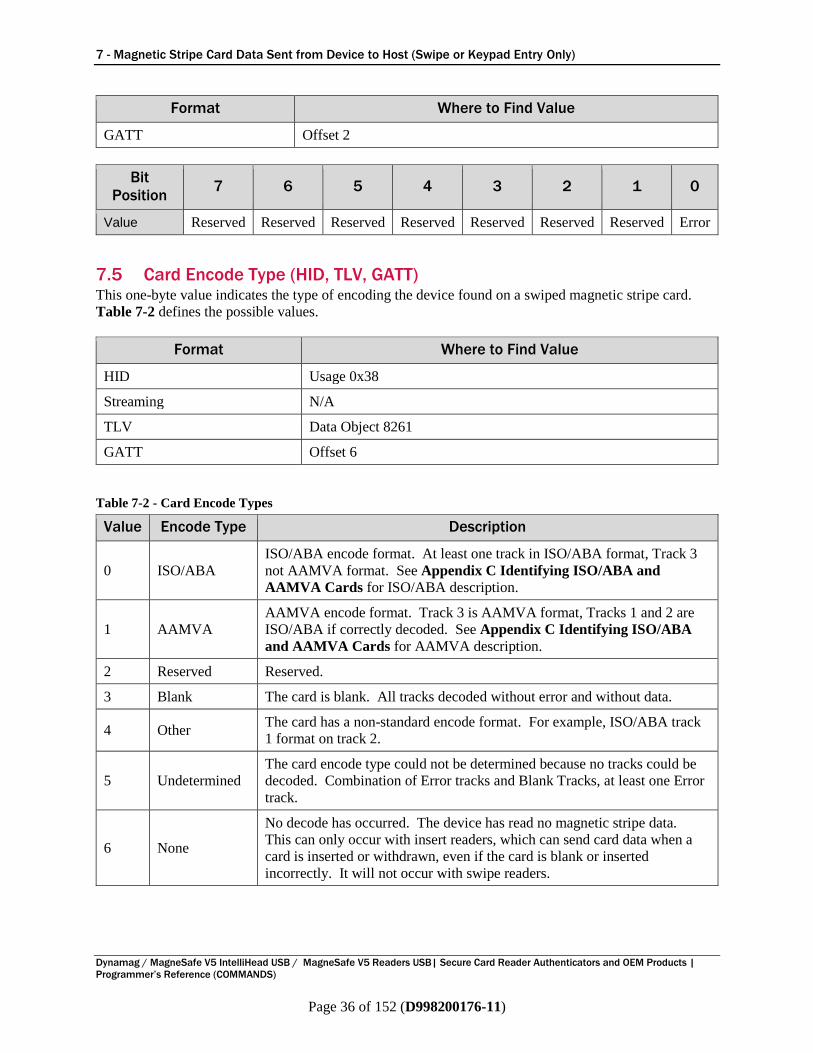
7 - Magnetic Stripe Card Data Sent from Device to Host (Swipe or Keypad Entry Only)
Dynamag / MagneSafe V5 IntelliHead USB / MagneSafe V5 Readers USB| Secure Card Reader Authenticators and OEM Products |
Programmer’s Reference (COMMANDS)
Page 36 of 152 (D998200176-11)
Format Where to Find Value
GATT Offset 2
Bit
Position 7 6 5 4 3 2 1 0
Value Reserved Reserved Reserved Reserved Reserved Reserved Reserved Error
7.5 Card Encode Type (HID, TLV, GATT) This one-byte value indicates the type of encoding the device found on a swiped magnetic stripe card.
Table 7-2 defines the possible values.
Format Where to Find Value
HID Usage 0x38
Streaming N/A
TLV Data Object 8261
GATT Offset 6
Table 7-2 - Card Encode Types
Value Encode Type Description
0 ISO/ABA
ISO/ABA encode format. At least one track in ISO/ABA format, Track 3
not AAMVA format. See Appendix C Identifying ISO/ABA and
AAMVA Cards for ISO/ABA description.
1 AAMVA
AAMVA encode format. Track 3 is AAMVA format, Tracks 1 and 2 are
ISO/ABA if correctly decoded. See Appendix C Identifying ISO/ABA
and AAMVA Cards for AAMVA description.
2 Reserved Reserved.
3 Blank The card is blank. All tracks decoded without error and without data.
4 Other The card has a non-standard encode format. For example, ISO/ABA track
1 format on track 2.
5 Undetermined
The card encode type could not be determined because no tracks could be
decoded. Combination of Error tracks and Blank Tracks, at least one Error
track.
6 None
No decode has occurred. The device has read no magnetic stripe data.
This can only occur with insert readers, which can send card data when a
card is inserted or withdrawn, even if the card is blank or inserted
incorrectly. It will not occur with swipe readers.

7 - Magnetic Stripe Card Data Sent from Device to Host (Swipe or Keypad Entry Only)
Dynamag / MagneSafe V5 IntelliHead USB / MagneSafe V5 Readers USB| Secure Card Reader Authenticators and OEM Products |
Programmer’s Reference (COMMANDS)
Page 37 of 152 (D998200176-11)
7.6 Device Encryption Status This two-byte value contains the Device Encryption Status in big endian byte order. Byte 1 is the least
significant byte; the LSB of byte 1 is status bit 0, and the LSB of byte 2 is status bit 15.
If the Encryption Enabled bit or Initial DUKPT Key Injected bit are not set, the device will send card
data it would usually encrypt as clear text, and will not include a valid DUKPT Key Serial Number.
When the DUKPT Keys Exhausted bit is set, the device will no longer read cards but will continue to
send Magnetic Stripe Card Data Sent from Device to Host (Swipe or Keypad Entry Only) to report
status. The data it sends to the host in this case will not include valid MagnePrint Status, Encrypted
MagnePrint Data, Masked Track Data, or Encrypted Track Data.
Format Where to Find Value
HID Usage 0x42
Streaming See Table 4-1 p. 27
TLV Data Object 8001
GATT Offset 493-494
The Device Encryption Status is defined as follows:
Bit Meaning
0 DUKPT keys exhausted (1 = Exhausted, 0 = Keys available)
1 Initial DUKPT key injected, always set to 1
2 Encryption Enabled, always set to 1
3 Authentication Required
4 Timed out waiting for cardholder to swipe card (N/A for Store and Forward devices)
8 Encryption Counter expired
9 Reserved
10 Reserved
11 DUKPT Variant used to encrypt Encrypted Track Data. 0 = PIN Variant, 1 = Data
Variant/Bidirectional (Configurable MSR Keys Only)
12 Reserved
13 Reserved
14 Unused (always set to 0)
15 Unused (always set to 0)
7.7 Encrypted Track Data If decodable track data exists for a given track, the device returns it in the corresponding Track x
Encrypted Data value, described in the subsections below.
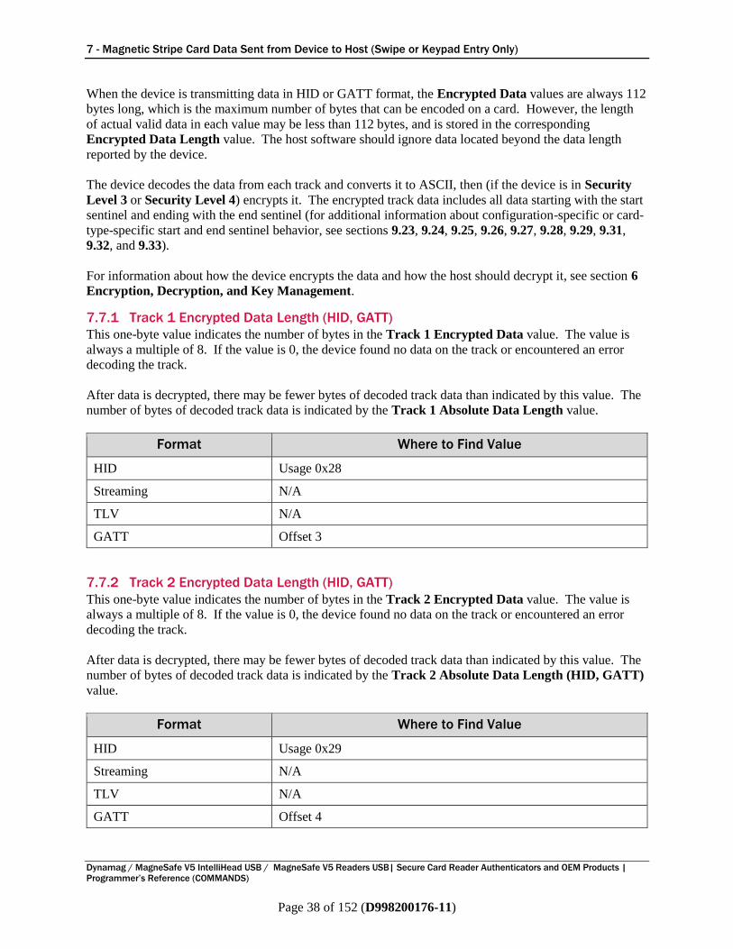
7 - Magnetic Stripe Card Data Sent from Device to Host (Swipe or Keypad Entry Only)
Dynamag / MagneSafe V5 IntelliHead USB / MagneSafe V5 Readers USB| Secure Card Reader Authenticators and OEM Products |
Programmer’s Reference (COMMANDS)
Page 38 of 152 (D998200176-11)
When the device is transmitting data in HID or GATT format, the Encrypted Data values are always 112
bytes long, which is the maximum number of bytes that can be encoded on a card. However, the length
of actual valid data in each value may be less than 112 bytes, and is stored in the corresponding
Encrypted Data Length value. The host software should ignore data located beyond the data length
reported by the device.
The device decodes the data from each track and converts it to ASCII, then (if the device is in Security
Level 3 or Security Level 4) encrypts it. The encrypted track data includes all data starting with the start
sentinel and ending with the end sentinel (for additional information about configuration-specific or card-
type-specific start and end sentinel behavior, see sections 9.23, 9.24, 9.25, 9.26, 9.27, 9.28, 9.29, 9.31,
9.32, and 9.33).
For information about how the device encrypts the data and how the host should decrypt it, see section 6
Encryption, Decryption, and Key Management.
7.7.1 Track 1 Encrypted Data Length (HID, GATT)
This one-byte value indicates the number of bytes in the Track 1 Encrypted Data value. The value is
always a multiple of 8. If the value is 0, the device found no data on the track or encountered an error
decoding the track.
After data is decrypted, there may be fewer bytes of decoded track data than indicated by this value. The
number of bytes of decoded track data is indicated by the Track 1 Absolute Data Length value.
Format Where to Find Value
HID Usage 0x28
Streaming N/A
TLV N/A
GATT Offset 3
7.7.2 Track 2 Encrypted Data Length (HID, GATT)
This one-byte value indicates the number of bytes in the Track 2 Encrypted Data value. The value is
always a multiple of 8. If the value is 0, the device found no data on the track or encountered an error
decoding the track.
After data is decrypted, there may be fewer bytes of decoded track data than indicated by this value. The
number of bytes of decoded track data is indicated by the Track 2 Absolute Data Length (HID, GATT)
value.
Format Where to Find Value
HID Usage 0x29
Streaming N/A
TLV N/A
GATT Offset 4

7 - Magnetic Stripe Card Data Sent from Device to Host (Swipe or Keypad Entry Only)
Dynamag / MagneSafe V5 IntelliHead USB / MagneSafe V5 Readers USB| Secure Card Reader Authenticators and OEM Products |
Programmer’s Reference (COMMANDS)
Page 39 of 152 (D998200176-11)
7.7.3 Track 3 Encrypted Data Length (HID, GATT, 3-Track Only)
This one-byte value indicates the number of bytes in the Track 3 Encrypted Data value. The value is
always a multiple of 8. If the value is 0, the device found no data on the track or encountered an error
decoding the track.
After data is decrypted, there may be fewer bytes of decoded track data than indicated by this value. The
number of bytes of decoded track data is indicated by the Track 3 Absolute Data Length value.
Format Where to Find Value
HID Usage 0x2A
Streaming N/A
TLV N/A
GATT Offset 5
7.7.4 Track 1 Absolute Data Length (HID, GATT)
This one-byte value indicates the number of usable bytes in the Track 1 Encrypted Data value after
decryption. If the value is 0, the device found no data on the track or encountered an error decoding the
track.
Format Where to Find Value
HID Usage 0x51
Streaming N/A
TLV N/A
GATT Offset 852
7.7.5 Track 2 Absolute Data Length (HID, GATT)
This one-byte value indicates the number of usable bytes in the Track 2 Encrypted Data value after
decryption. If the value is 0, the device found no data on the track or encountered an error decoding the
track.
Format Where to Find Value
HID Usage 0x52
Streaming N/A
TLV N/A
GATT Offset 853
7.7.6 Track 3 Absolute Data Length (HID, GATT, 3-Track Only)
This one-byte value indicates the number of usable bytes in the Track 3 Encrypted Data value after
decryption. If the value is 0, the device found no data on the track or encountered an error decoding the
track.

7 - Magnetic Stripe Card Data Sent from Device to Host (Swipe or Keypad Entry Only)
Dynamag / MagneSafe V5 IntelliHead USB / MagneSafe V5 Readers USB| Secure Card Reader Authenticators and OEM Products |
Programmer’s Reference (COMMANDS)
Page 40 of 152 (D998200176-11)
Format Where to Find Value
HID Usage 0x53
Streaming N/A
TLV N/A
GATT Offset 854
7.7.7 Track 1 Encrypted Data
Format Where to Find Value
HID Usage 0x30
Streaming See Table 4-1 p. 27
TLV Data Object 8215
GATT Offset 7-118
7.7.8 Track 2 Encrypted Data
Format Where to Find Value
HID Usage 0x31
Streaming See Table 4-1 p. 27
TLV Data Object 8216
GATT Offset 119-230
7.7.9 Track 3 Encrypted Data
On 2-track devices (see Table 2-2 - Device Features), this value is included in incoming data as a null
value.
Format Where to Find Value
HID Usage 0x32
Streaming See Table 4-1 p. 27
TLV Data Object 8217
GATT Offset 231-342
7.8 MagnePrint Status This four-byte value contains 32 bits of MagnePrint status information in little endian byte order. Byte 1
is the least significant byte and its LSB is status bit 0. Byte 4 is the most significant byte and its MSB is
status bit 31. Table 7-3 provides an example showing the meaning of the MagnePrint Status bits for a
specific value. If Property 0x15 - MagnePrint Flags is set to not transmit MagnePrint data, the device
will not include this value.

7 - Magnetic Stripe Card Data Sent from Device to Host (Swipe or Keypad Entry Only)
Dynamag / MagneSafe V5 IntelliHead USB / MagneSafe V5 Readers USB| Secure Card Reader Authenticators and OEM Products |
Programmer’s Reference (COMMANDS)
Page 41 of 152 (D998200176-11)
Bit 0 = MagnePrint capable flag
Bits 1 to 15 = Product revision & mode
Bit 16 = Reserved
Bit 17 = Reserved for noise measurement
Bit 18 = Swipe too slow
Bit 19 = Swipe too fast
Bit 20 = Reserved
Bit 21 = Actual card swipe direction (0 = Forward, 1 = Reverse)
Bits 22-31 = Reserved
Format Where to Find Value
HID Usage 0x23
Streaming See Table 4-1 p. 27
TLV Data Object 8263
GATT Offset 344-347
Thinking about the value in hexadecimal notation, each hexadecimal digit represents 4 bits. For example,
Table 7-3 shows a MagnePrint Status where the characters are A1050000.
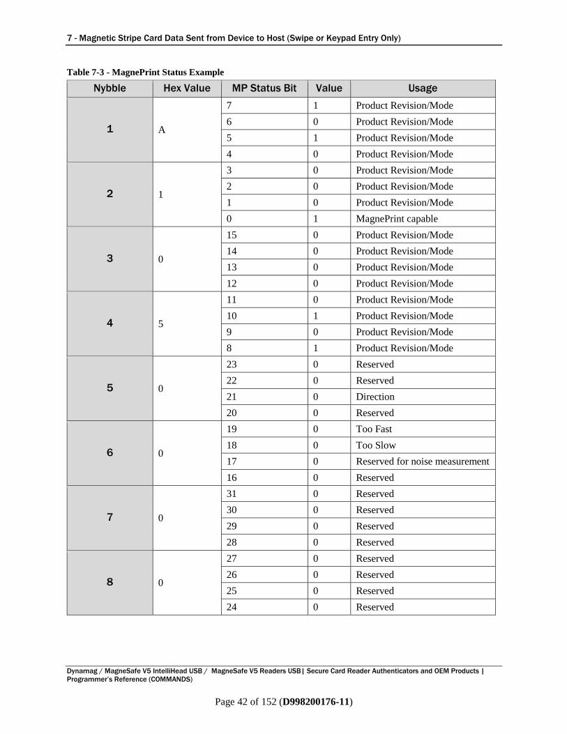
7 - Magnetic Stripe Card Data Sent from Device to Host (Swipe or Keypad Entry Only)
Dynamag / MagneSafe V5 IntelliHead USB / MagneSafe V5 Readers USB| Secure Card Reader Authenticators and OEM Products |
Programmer’s Reference (COMMANDS)
Page 42 of 152 (D998200176-11)
Table 7-3 - MagnePrint Status Example
Nybble Hex Value MP Status Bit Value Usage
1 A
7 1 Product Revision/Mode
6 0 Product Revision/Mode
5 1 Product Revision/Mode
4 0 Product Revision/Mode
2 1
3 0 Product Revision/Mode
2 0 Product Revision/Mode
1 0 Product Revision/Mode
0 1 MagnePrint capable
3 0
15 0 Product Revision/Mode
14 0 Product Revision/Mode
13 0 Product Revision/Mode
12 0 Product Revision/Mode
4 5
11 0 Product Revision/Mode
10 1 Product Revision/Mode
9 0 Product Revision/Mode
8 1 Product Revision/Mode
5 0
23 0 Reserved
22 0 Reserved
21 0 Direction
20 0 Reserved
6 0
19 0 Too Fast
18 0 Too Slow
17 0 Reserved for noise measurement
16 0 Reserved
7 0
31 0 Reserved
30 0 Reserved
29 0 Reserved
28 0 Reserved
8 0
27 0 Reserved
26 0 Reserved
25 0 Reserved
24 0 Reserved
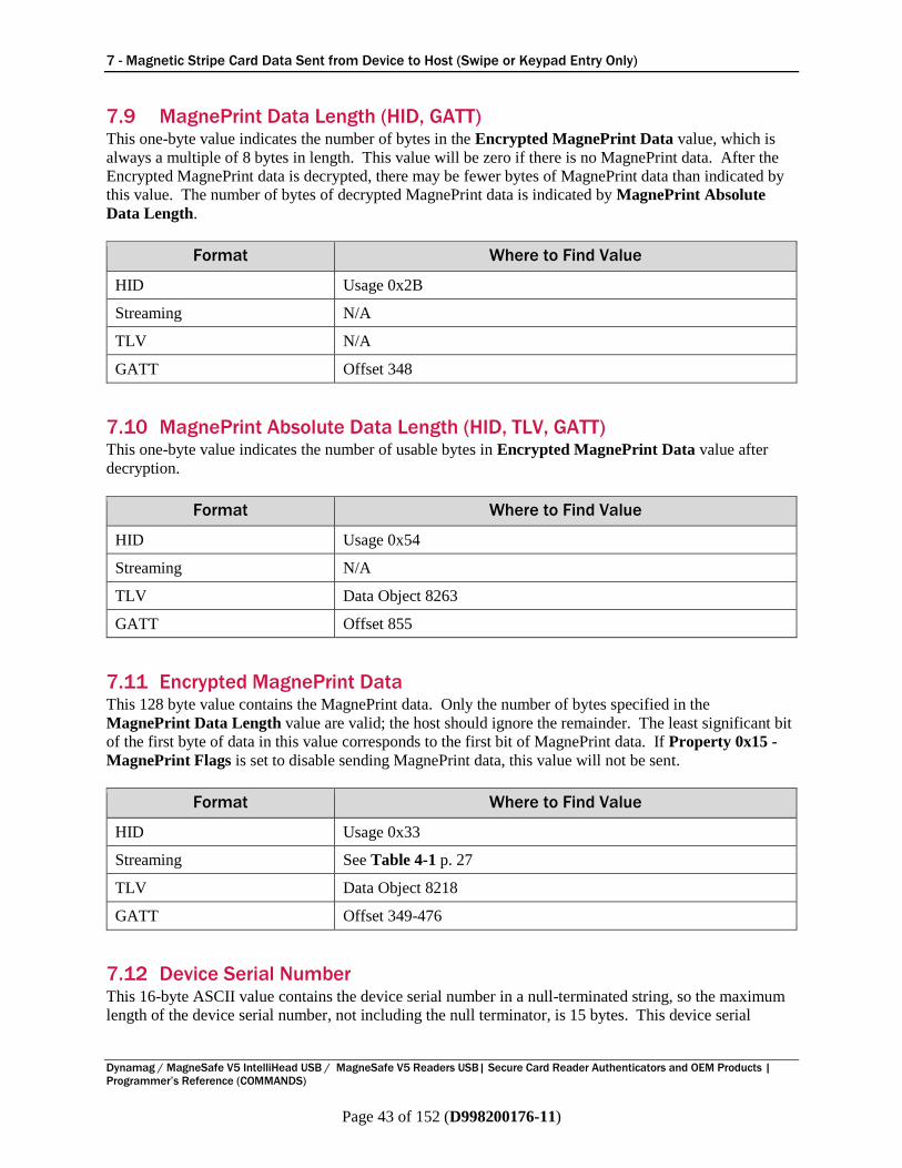
7 - Magnetic Stripe Card Data Sent from Device to Host (Swipe or Keypad Entry Only)
Dynamag / MagneSafe V5 IntelliHead USB / MagneSafe V5 Readers USB| Secure Card Reader Authenticators and OEM Products |
Programmer’s Reference (COMMANDS)
Page 43 of 152 (D998200176-11)
7.9 MagnePrint Data Length (HID, GATT) This one-byte value indicates the number of bytes in the Encrypted MagnePrint Data value, which is
always a multiple of 8 bytes in length. This value will be zero if there is no MagnePrint data. After the
Encrypted MagnePrint data is decrypted, there may be fewer bytes of MagnePrint data than indicated by
this value. The number of bytes of decrypted MagnePrint data is indicated by MagnePrint Absolute
Data Length.
Format Where to Find Value
HID Usage 0x2B
Streaming N/A
TLV N/A
GATT Offset 348
7.10 MagnePrint Absolute Data Length (HID, TLV, GATT) This one-byte value indicates the number of usable bytes in Encrypted MagnePrint Data value after
decryption.
Format Where to Find Value
HID Usage 0x54
Streaming N/A
TLV Data Object 8263
GATT Offset 855
7.11 Encrypted MagnePrint Data This 128 byte value contains the MagnePrint data. Only the number of bytes specified in the
MagnePrint Data Length value are valid; the host should ignore the remainder. The least significant bit
of the first byte of data in this value corresponds to the first bit of MagnePrint data. If Property 0x15 -
MagnePrint Flags is set to disable sending MagnePrint data, this value will not be sent.
Format Where to Find Value
HID Usage 0x33
Streaming See Table 4-1 p. 27
TLV Data Object 8218
GATT Offset 349-476
7.12 Device Serial Number This 16-byte ASCII value contains the device serial number in a null-terminated string, so the maximum
length of the device serial number, not including the null terminator, is 15 bytes. This device serial

7 - Magnetic Stripe Card Data Sent from Device to Host (Swipe or Keypad Entry Only)
Dynamag / MagneSafe V5 IntelliHead USB / MagneSafe V5 Readers USB| Secure Card Reader Authenticators and OEM Products |
Programmer’s Reference (COMMANDS)
Page 44 of 152 (D998200176-11)
number can also be retrieved and set with Property 0x03 - Device Serial Num. This value is stored in
non-volatile memory, so it will persist when the device is power cycled.
Format Where to Find Value
HID Usage 0x40
Streaming See Table 4-1 p. 27
TLV Data Object 8102
GATT Offset 477-492
7.13 Masked Track Data If decodable track data exists for a given track, the device returns a masked version of the data in the
Track x Masked Track Data value for that track. The masked version includes one byte of data for each
character decoded from the track, starting with the Start Sentinel and ending with the End Sentinel.
Much of the data is masked; the device sends a specified mask character instead of the actual character
read from the track. Which characters are masked depends on the card data format: Only ISO/ABA
(Financial Cards with ISO/IEC 7813 Format code B) and AAMVA cards are selectively masked; all
other card types are either entirely masked or sent totally in the clear. More detail about masking is
included in the sections below about each specific track.
There are separate masking settings for ISO/ABA format cards and AAMVA format cards (See Property
0x07 - ISO Track Mask and Property 0x08 - AAMVA Track Mask for more information). Each of
these settings allows the host software to specify masking details for the Primary Account Number and
Driver’s License / ID Number (DL/ID#), the masking character to be used, and whether a correction
should be applied to make the Mod 10 (Luhn algorithm) digit at the end of the number be correct.
Table 7-4 provides an example of data from tracks 1, 2, and 3 of a swiped ISO/ABA card after it has been
decrypted or if the device has sent it in the clear. Table 7-5 shows the same data as it might appear with a
specific set of Masked Track Data rules applied.
Table 7-4 – Sample ISO/ABA Swiped Track Data, Clear Text / Decrypted
Sample ISO/ABA Swiped Track Data, Clear Text / Decrypted
Track 1 %B6011000995500000^ TEST CARD ^15121015432112345678?
Track 2 ;6011000995500000=15121015432112345678?
Track 3 ;6011000995500000=15121015432112345678333333333333333333333?
Table 7-5 – Sample ISO/ABA Swiped Track Data, Masked
Sample ISO/ABA Swiped Track Data, Masked
Track 1 %B6011000020000000^ TEST CARD ^15120000000000000000?
Track 2 ;6011000020000000=15120000000000000000?
Track 3 ;6011000020000000=00000000000000000000000000000000000000000?
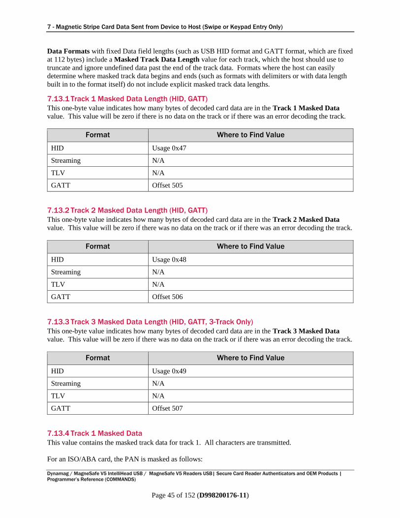
7 - Magnetic Stripe Card Data Sent from Device to Host (Swipe or Keypad Entry Only)
Dynamag / MagneSafe V5 IntelliHead USB / MagneSafe V5 Readers USB| Secure Card Reader Authenticators and OEM Products |
Programmer’s Reference (COMMANDS)
Page 45 of 152 (D998200176-11)
Data Formats with fixed Data field lengths (such as USB HID format and GATT format, which are fixed
at 112 bytes) include a Masked Track Data Length value for each track, which the host should use to
truncate and ignore undefined data past the end of the track data. Formats where the host can easily
determine where masked track data begins and ends (such as formats with delimiters or with data length
built in to the format itself) do not include explicit masked track data lengths.
7.13.1 Track 1 Masked Data Length (HID, GATT)
This one-byte value indicates how many bytes of decoded card data are in the Track 1 Masked Data
value. This value will be zero if there is no data on the track or if there was an error decoding the track.
Format Where to Find Value
HID Usage 0x47
Streaming N/A
TLV N/A
GATT Offset 505
7.13.2 Track 2 Masked Data Length (HID, GATT)
This one-byte value indicates how many bytes of decoded card data are in the Track 2 Masked Data
value. This value will be zero if there was no data on the track or if there was an error decoding the track.
Format Where to Find Value
HID Usage 0x48
Streaming N/A
TLV N/A
GATT Offset 506
7.13.3 Track 3 Masked Data Length (HID, GATT, 3-Track Only)
This one-byte value indicates how many bytes of decoded card data are in the Track 3 Masked Data
value. This value will be zero if there was no data on the track or if there was an error decoding the track.
Format Where to Find Value
HID Usage 0x49
Streaming N/A
TLV N/A
GATT Offset 507
7.13.4 Track 1 Masked Data
This value contains the masked track data for track 1. All characters are transmitted.
For an ISO/ABA card, the PAN is masked as follows:
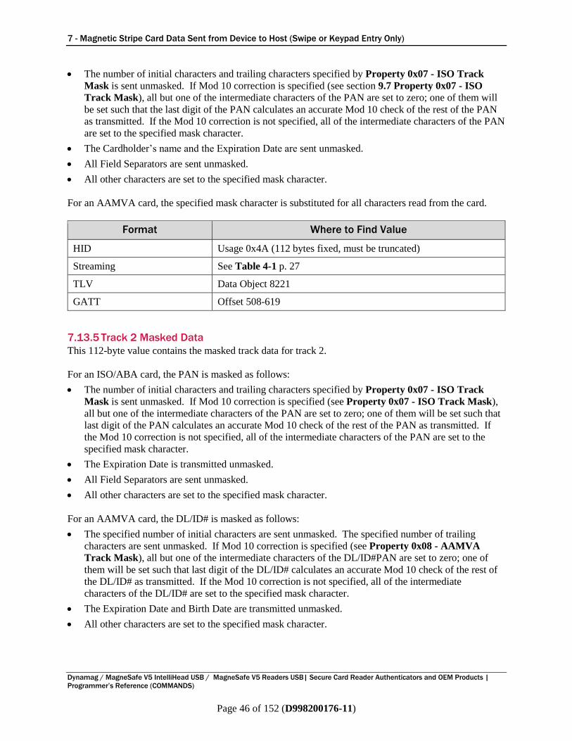
7 - Magnetic Stripe Card Data Sent from Device to Host (Swipe or Keypad Entry Only)
Dynamag / MagneSafe V5 IntelliHead USB / MagneSafe V5 Readers USB| Secure Card Reader Authenticators and OEM Products |
Programmer’s Reference (COMMANDS)
Page 46 of 152 (D998200176-11)
The number of initial characters and trailing characters specified by Property 0x07 - ISO Track
Mask is sent unmasked. If Mod 10 correction is specified (see section 9.7 Property 0x07 - ISO
Track Mask), all but one of the intermediate characters of the PAN are set to zero; one of them will
be set such that the last digit of the PAN calculates an accurate Mod 10 check of the rest of the PAN
as transmitted. If the Mod 10 correction is not specified, all of the intermediate characters of the PAN
are set to the specified mask character.
The Cardholder’s name and the Expiration Date are sent unmasked.
All Field Separators are sent unmasked.
All other characters are set to the specified mask character.
For an AAMVA card, the specified mask character is substituted for all characters read from the card.
Format Where to Find Value
HID Usage 0x4A (112 bytes fixed, must be truncated)
Streaming See Table 4-1 p. 27
TLV Data Object 8221
GATT Offset 508-619
7.13.5 Track 2 Masked Data
This 112-byte value contains the masked track data for track 2.
For an ISO/ABA card, the PAN is masked as follows:
The number of initial characters and trailing characters specified by Property 0x07 - ISO Track
Mask is sent unmasked. If Mod 10 correction is specified (see Property 0x07 - ISO Track Mask),
all but one of the intermediate characters of the PAN are set to zero; one of them will be set such that
last digit of the PAN calculates an accurate Mod 10 check of the rest of the PAN as transmitted. If
the Mod 10 correction is not specified, all of the intermediate characters of the PAN are set to the
specified mask character.
The Expiration Date is transmitted unmasked.
All Field Separators are sent unmasked.
All other characters are set to the specified mask character.
For an AAMVA card, the DL/ID# is masked as follows:
The specified number of initial characters are sent unmasked. The specified number of trailing
characters are sent unmasked. If Mod 10 correction is specified (see Property 0x08 - AAMVA
Track Mask), all but one of the intermediate characters of the DL/ID#PAN are set to zero; one of
them will be set such that last digit of the DL/ID# calculates an accurate Mod 10 check of the rest of
the DL/ID# as transmitted. If the Mod 10 correction is not specified, all of the intermediate
characters of the DL/ID# are set to the specified mask character.
The Expiration Date and Birth Date are transmitted unmasked.
All other characters are set to the specified mask character.

7 - Magnetic Stripe Card Data Sent from Device to Host (Swipe or Keypad Entry Only)
Dynamag / MagneSafe V5 IntelliHead USB / MagneSafe V5 Readers USB| Secure Card Reader Authenticators and OEM Products |
Programmer’s Reference (COMMANDS)
Page 47 of 152 (D998200176-11)
Format Where to Find Value
HID Usage 0x4B (112 bytes fixed, must be truncated)
Streaming See Table 4-1 p. 27
TLV Data Object 8222
GATT Offset 620-731
7.13.6 Track 3 Masked Data (3-Track Only)
This 112-byte value contains the Masked Track Data for track 3. On 2-track devices (see Table 2-2 -
Device Features), this value is not included in the incoming data.
For an ISO/ABA card, the PAN is masked as follows:
The number of initial characters and trailing characters specified by Property 0x07 - ISO Track
Mask is sent unmasked. If Mod 10 correction is specified (see section 9.7 Property 0x07 - ISO
Track Mask), all but one of the intermediate characters of the PAN are set to zero; one of them will
be set such that last digit of the PAN calculates an accurate Mod 10 check of the rest of the PAN as
transmitted. If the Mod 10 correction is not specified, all of the intermediate characters of the PAN
are set to the specified mask character.
All Field Separators are sent unmasked.
All other characters are set to the specified mask character.
For an AAMVA card, the specified mask character is substituted for all characters read from the card.
Format Where to Find Value
HID Usage 0x4C (112 bytes fixed, must be truncated)
Streaming See Table 4-1 p. 27
TLV Data Object 8223
GATT Offset 732-843
7.14 Encrypted Session ID This 8-byte value contains the encrypted version of the current Session ID. Its primary purpose is to
prevent replays. After a card is read, this property will be encrypted, along with the card data, and
supplied as part of the transaction message. The clear text version will never be transmitted. To avoid
replay, the host software should set the Session ID property before a transaction, and verify that the
Encrypted Session ID returned with card data decrypts to the original value it set.
Format Where to Find Value
HID Usage 0x50
Streaming See Table 4-1 p. 27
TLV Data Object 8309
GATT Offset 844-851
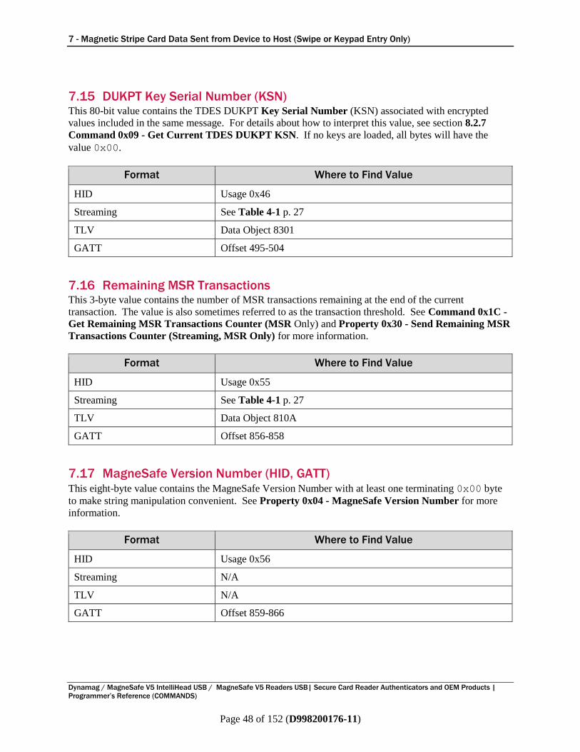
7 - Magnetic Stripe Card Data Sent from Device to Host (Swipe or Keypad Entry Only)
Dynamag / MagneSafe V5 IntelliHead USB / MagneSafe V5 Readers USB| Secure Card Reader Authenticators and OEM Products |
Programmer’s Reference (COMMANDS)
Page 48 of 152 (D998200176-11)
7.15 DUKPT Key Serial Number (KSN) This 80-bit value contains the TDES DUKPT Key Serial Number (KSN) associated with encrypted
values included in the same message. For details about how to interpret this value, see section 8.2.7
Command 0x09 - Get Current TDES DUKPT KSN. If no keys are loaded, all bytes will have the
value 0x00.
Format Where to Find Value
HID Usage 0x46
Streaming See Table 4-1 p. 27
TLV Data Object 8301
GATT Offset 495-504
7.16 Remaining MSR Transactions This 3-byte value contains the number of MSR transactions remaining at the end of the current
transaction. The value is also sometimes referred to as the transaction threshold. See Command 0x1C -
Get Remaining MSR Transactions Counter (MSR Only) and Property 0x30 - Send Remaining MSR
Transactions Counter (Streaming, MSR Only) for more information.
Format Where to Find Value
HID Usage 0x55
Streaming See Table 4-1 p. 27
TLV Data Object 810A
GATT Offset 856-858
7.17 MagneSafe Version Number (HID, GATT) This eight-byte value contains the MagneSafe Version Number with at least one terminating 0x00 byte
to make string manipulation convenient. See Property 0x04 - MagneSafe Version Number for more
information.
Format Where to Find Value
HID Usage 0x56
Streaming N/A
TLV N/A
GATT Offset 859-866
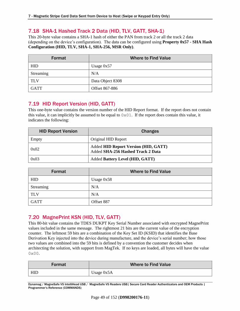
7 - Magnetic Stripe Card Data Sent from Device to Host (Swipe or Keypad Entry Only)
Dynamag / MagneSafe V5 IntelliHead USB / MagneSafe V5 Readers USB| Secure Card Reader Authenticators and OEM Products |
Programmer’s Reference (COMMANDS)
Page 49 of 152 (D998200176-11)
7.18 SHA-1 Hashed Track 2 Data (HID, TLV, GATT, SHA-1) This 20-byte value contains a SHA-1 hash of either the PAN from track 2 or all the track 2 data
(depending on the device’s configuration). The data can be configured using Property 0x57 - SHA Hash
Configuration (HID, TLV, SHA-1, SHA-256, MSR Only).
Format Where to Find Value
HID Usage 0x57
Streaming N/A
TLV Data Object 8308
GATT Offset 867-886
7.19 HID Report Version (HID, GATT) This one-byte value contains the version number of the HID Report format. If the report does not contain
this value, it can implicitly be assumed to be equal to 0x01. If the report does contain this value, it
indicates the following:
HID Report Version Changes
Empty Original HID Report
0x02 Added HID Report Version (HID, GATT)
Added SHA-256 Hashed Track 2 Data
0x03 Added Battery Level (HID, GATT)
Format Where to Find Value
HID Usage 0x58
Streaming N/A
TLV N/A
GATT Offset 887
7.20 MagnePrint KSN (HID, TLV, GATT) This 80-bit value contains the TDES DUKPT Key Serial Number associated with encrypted MagnePrint
values included in the same message. The rightmost 21 bits are the current value of the encryption
counter. The leftmost 59 bits are a combination of the Key Set ID (KSID) that identifies the Base
Derivation Key injected into the device during manufacture, and the device’s serial number; how those
two values are combined into the 59 bits is defined by a convention the customer decides when
architecting the solution, with support from MagTek. If no keys are loaded, all bytes will have the value
0x00.
Format Where to Find Value
HID Usage 0x5A
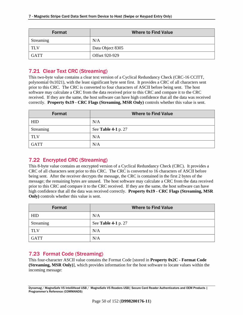
7 - Magnetic Stripe Card Data Sent from Device to Host (Swipe or Keypad Entry Only)
Dynamag / MagneSafe V5 IntelliHead USB / MagneSafe V5 Readers USB| Secure Card Reader Authenticators and OEM Products |
Programmer’s Reference (COMMANDS)
Page 50 of 152 (D998200176-11)
Format Where to Find Value
Streaming N/A
TLV Data Object 8305
GATT Offset 920-929
7.21 Clear Text CRC (Streaming) This two-byte value contains a clear text version of a Cyclical Redundancy Check (CRC-16 CCITT,
polynomial 0x1021), with the least significant byte sent first. It provides a CRC of all characters sent
prior to this CRC. The CRC is converted to four characters of ASCII before being sent. The host
software may calculate a CRC from the data received prior to this CRC and compare it to the CRC
received. If they are the same, the host software can have high confidence that all the data was received
correctly. Property 0x19 - CRC Flags (Streaming, MSR Only) controls whether this value is sent.
Format Where to Find Value
HID N/A
Streaming See Table 4-1 p. 27
TLV N/A
GATT N/A
7.22 Encrypted CRC (Streaming) This 8-byte value contains an encrypted version of a Cyclical Redundancy Check (CRC). It provides a
CRC of all characters sent prior to this CRC. The CRC is converted to 16 characters of ASCII before
being sent. After the receiver decrypts the message, the CRC is contained in the first 2 bytes of the
message; the remaining bytes are unused. The host software may calculate a CRC from the data received
prior to this CRC and compare it to the CRC received. If they are the same, the host software can have
high confidence that all the data was received correctly. Property 0x19 - CRC Flags (Streaming, MSR
Only) controls whether this value is sent.
Format Where to Find Value
HID N/A
Streaming See Table 4-1 p. 27
TLV N/A
GATT N/A
7.23 Format Code (Streaming) This four-character ASCII value contains the Format Code [stored in Property 0x2C - Format Code
(Streaming, MSR Only)], which provides information for the host software to locate values within the
incoming message:

7 - Magnetic Stripe Card Data Sent from Device to Host (Swipe or Keypad Entry Only)
Dynamag / MagneSafe V5 IntelliHead USB / MagneSafe V5 Readers USB| Secure Card Reader Authenticators and OEM Products |
Programmer’s Reference (COMMANDS)
Page 51 of 152 (D998200176-11)
Format Where to Find Value
HID N/A
Streaming See Table 4-1 p. 27
TLV N/A
GATT N/A
7.24 Battery Level (HID, GATT) This one-byte value contains the battery level of the device between 0% and 100%. 0x00 represents the
lowest safe operating voltage; 0x64 means the battery is at full voltage. When the device is powered by
USB, it will always return 100%. This field should be ignored for devices that do not contain a battery.
Format Where to Find Value
HID Usage 0x5B
Streaming N/A
TLV N/A
GATT Offset 930
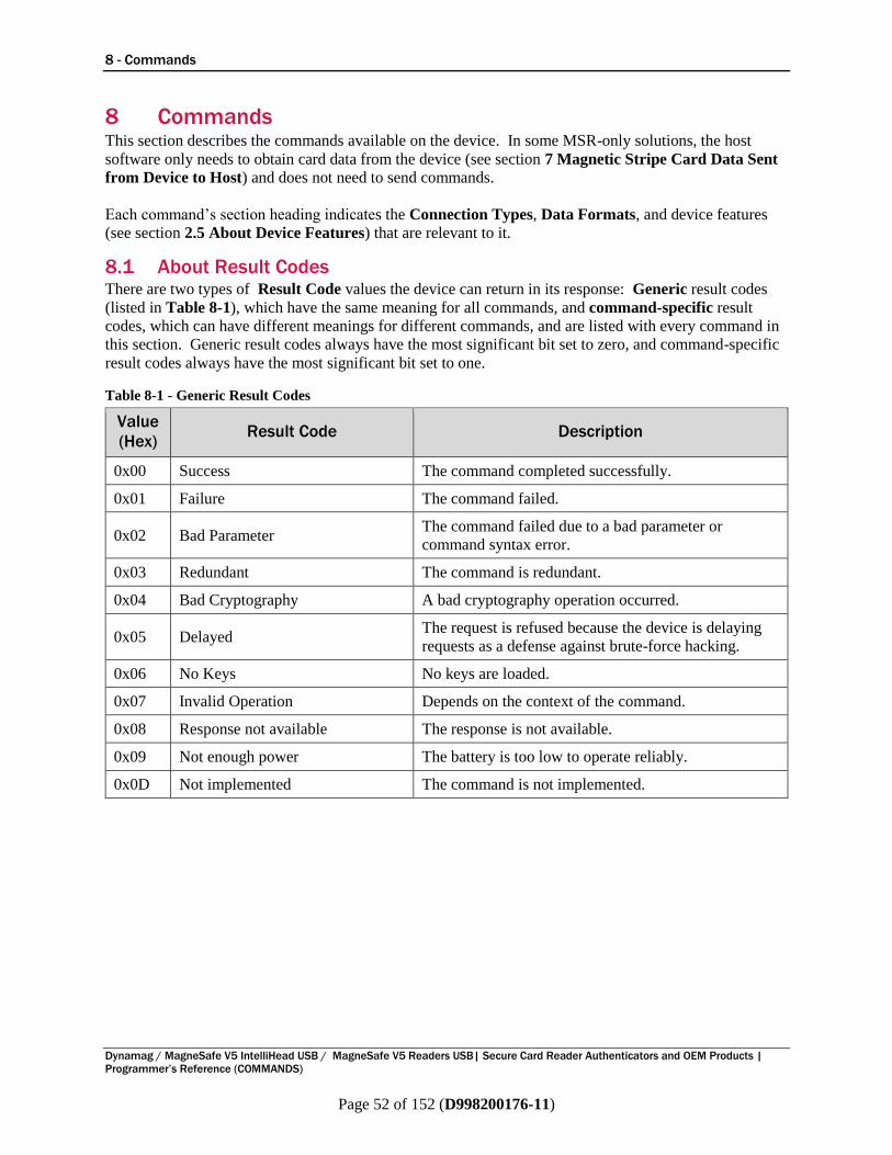
8 - Commands
Dynamag / MagneSafe V5 IntelliHead USB / MagneSafe V5 Readers USB| Secure Card Reader Authenticators and OEM Products |
Programmer’s Reference (COMMANDS)
Page 52 of 152 (D998200176-11)
8 Commands This section describes the commands available on the device. In some MSR-only solutions, the host
software only needs to obtain card data from the device (see section 7 Magnetic Stripe Card Data Sent
from Device to Host) and does not need to send commands.
Each command’s section heading indicates the Connection Types, Data Formats, and device features
(see section 2.5 About Device Features) that are relevant to it.
8.1 About Result Codes There are two types of Result Code values the device can return in its response: Generic result codes
(listed in Table 8-1), which have the same meaning for all commands, and command-specific result
codes, which can have different meanings for different commands, and are listed with every command in
this section. Generic result codes always have the most significant bit set to zero, and command-specific
result codes always have the most significant bit set to one.
Table 8-1 - Generic Result Codes
Value
(Hex) Result Code Description
0x00 Success The command completed successfully.
0x01 Failure The command failed.
0x02 Bad Parameter The command failed due to a bad parameter or
command syntax error.
0x03 Redundant The command is redundant.
0x04 Bad Cryptography A bad cryptography operation occurred.
0x05 Delayed The request is refused because the device is delaying
requests as a defense against brute-force hacking.
0x06 No Keys No keys are loaded.
0x07 Invalid Operation Depends on the context of the command.
0x08 Response not available The response is not available.
0x09 Not enough power The battery is too low to operate reliably.
0x0D Not implemented The command is not implemented.
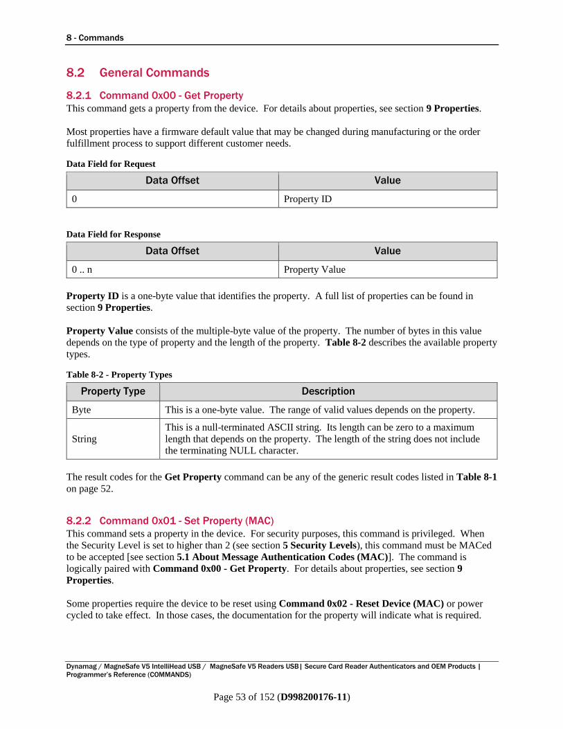
8 - Commands
Dynamag / MagneSafe V5 IntelliHead USB / MagneSafe V5 Readers USB| Secure Card Reader Authenticators and OEM Products |
Programmer’s Reference (COMMANDS)
Page 53 of 152 (D998200176-11)
8.2 General Commands
8.2.1 Command 0x00 - Get Property
This command gets a property from the device. For details about properties, see section 9 Properties.
Most properties have a firmware default value that may be changed during manufacturing or the order
fulfillment process to support different customer needs.
Data Field for Request
Data Offset Value
0 Property ID
Data Field for Response
Data Offset Value
0 .. n Property Value
Property ID is a one-byte value that identifies the property. A full list of properties can be found in
section 9 Properties.
Property Value consists of the multiple-byte value of the property. The number of bytes in this value
depends on the type of property and the length of the property. Table 8-2 describes the available property
types.
Table 8-2 - Property Types
Property Type Description
Byte This is a one-byte value. The range of valid values depends on the property.
String
This is a null-terminated ASCII string. Its length can be zero to a maximum
length that depends on the property. The length of the string does not include
the terminating NULL character.
The result codes for the Get Property command can be any of the generic result codes listed in Table 8-1
on page 52.
8.2.2 Command 0x01 - Set Property (MAC)
This command sets a property in the device. For security purposes, this command is privileged. When
the Security Level is set to higher than 2 (see section 5 Security Levels), this command must be MACed
to be accepted [see section 5.1 About Message Authentication Codes (MAC)]. The command is
logically paired with Command 0x00 - Get Property. For details about properties, see section 9
Properties.
Some properties require the device to be reset using Command 0x02 - Reset Device (MAC) or power
cycled to take effect. In those cases, the documentation for the property will indicate what is required.
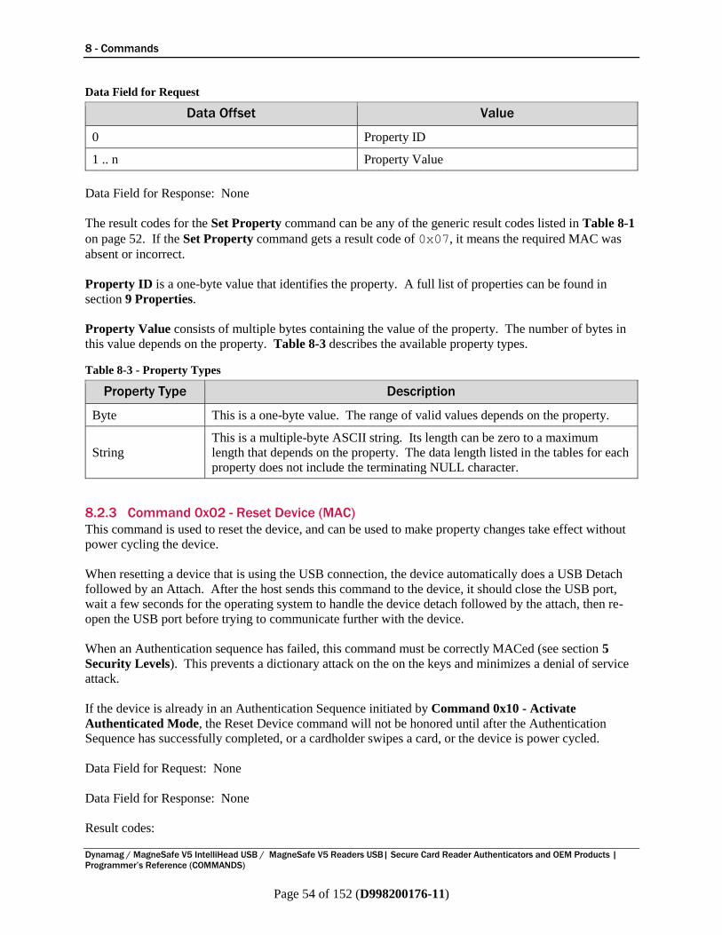
8 - Commands
Dynamag / MagneSafe V5 IntelliHead USB / MagneSafe V5 Readers USB| Secure Card Reader Authenticators and OEM Products |
Programmer’s Reference (COMMANDS)
Page 54 of 152 (D998200176-11)
Data Field for Request
Data Offset Value
0 Property ID
1 .. n Property Value
Data Field for Response: None
The result codes for the Set Property command can be any of the generic result codes listed in Table 8-1
on page 52. If the Set Property command gets a result code of 0x07, it means the required MAC was
absent or incorrect.
Property ID is a one-byte value that identifies the property. A full list of properties can be found in
section 9 Properties.
Property Value consists of multiple bytes containing the value of the property. The number of bytes in
this value depends on the property. Table 8-3 describes the available property types.
Table 8-3 - Property Types
Property Type Description
Byte This is a one-byte value. The range of valid values depends on the property.
String
This is a multiple-byte ASCII string. Its length can be zero to a maximum
length that depends on the property. The data length listed in the tables for each
property does not include the terminating NULL character.
8.2.3 Command 0x02 - Reset Device (MAC)
This command is used to reset the device, and can be used to make property changes take effect without
power cycling the device.
When resetting a device that is using the USB connection, the device automatically does a USB Detach
followed by an Attach. After the host sends this command to the device, it should close the USB port,
wait a few seconds for the operating system to handle the device detach followed by the attach, then re-
open the USB port before trying to communicate further with the device.
When an Authentication sequence has failed, this command must be correctly MACed (see section 5
Security Levels). This prevents a dictionary attack on the on the keys and minimizes a denial of service
attack.
If the device is already in an Authentication Sequence initiated by Command 0x10 - Activate
Authenticated Mode, the Reset Device command will not be honored until after the Authentication
Sequence has successfully completed, or a cardholder swipes a card, or the device is power cycled.
Data Field for Request: None
Data Field for Response: None
Result codes:
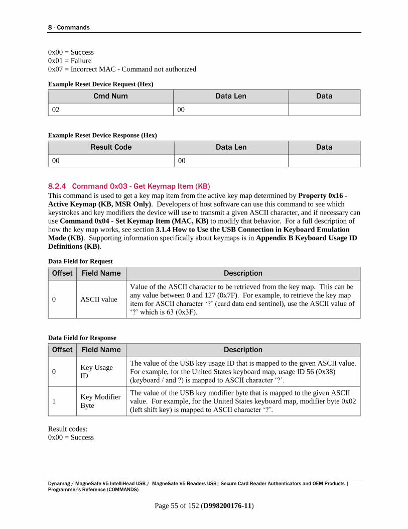
8 - Commands
Dynamag / MagneSafe V5 IntelliHead USB / MagneSafe V5 Readers USB| Secure Card Reader Authenticators and OEM Products |
Programmer’s Reference (COMMANDS)
Page 55 of 152 (D998200176-11)
0x00 = Success
0x01 = Failure
0x07 = Incorrect MAC - Command not authorized
Example Reset Device Request (Hex)
Cmd Num Data Len Data
02 00
Example Reset Device Response (Hex)
Result Code Data Len Data
00 00
8.2.4 Command 0x03 - Get Keymap Item (KB)
This command is used to get a key map item from the active key map determined by Property 0x16 -
Active Keymap (KB, MSR Only). Developers of host software can use this command to see which
keystrokes and key modifiers the device will use to transmit a given ASCII character, and if necessary can
use Command 0x04 - Set Keymap Item (MAC, KB) to modify that behavior. For a full description of
how the key map works, see section 3.1.4 How to Use the USB Connection in Keyboard Emulation
Mode (KB). Supporting information specifically about keymaps is in Appendix B Keyboard Usage ID
Definitions (KB).
Data Field for Request
Offset Field Name Description
0 ASCII value
Value of the ASCII character to be retrieved from the key map. This can be
any value between 0 and 127 (0x7F). For example, to retrieve the key map
item for ASCII character ‘?’ (card data end sentinel), use the ASCII value of
‘?’ which is 63 (0x3F).
Data Field for Response
Offset Field Name Description
0 Key Usage
ID
The value of the USB key usage ID that is mapped to the given ASCII value.
For example, for the United States keyboard map, usage ID 56 (0x38)
(keyboard / and ?) is mapped to ASCII character ‘?’.
1 Key Modifier
Byte
The value of the USB key modifier byte that is mapped to the given ASCII
value. For example, for the United States keyboard map, modifier byte 0x02
(left shift key) is mapped to ASCII character ‘?’.
Result codes:
0x00 = Success
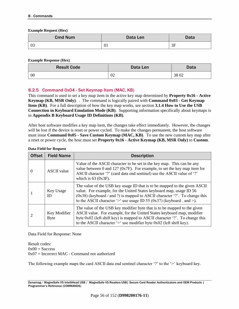
8 - Commands
Dynamag / MagneSafe V5 IntelliHead USB / MagneSafe V5 Readers USB| Secure Card Reader Authenticators and OEM Products |
Programmer’s Reference (COMMANDS)
Page 56 of 152 (D998200176-11)
Example Request (Hex)
Cmd Num Data Len Data
03 01 3F
Example Response (Hex)
Result Code Data Len Data
00 02 38 02
8.2.5 Command 0x04 - Set Keymap Item (MAC, KB)
This command is used to set a key map item in the active key map determined by Property 0x16 - Active
Keymap (KB, MSR Only). . The command is logically paired with Command 0x03 - Get Keymap
Item (KB). For a full description of how the key map works, see section 3.1.4 How to Use the USB
Connection in Keyboard Emulation Mode (KB). Supporting information specifically about keymaps is
in Appendix B Keyboard Usage ID Definitions (KB).
After host software modifies a key map item, the changes take effect immediately. However, the changes
will be lost if the device is reset or power cycled. To make the changes permanent, the host software
must issue Command 0x05 - Save Custom Keymap (MAC, KB). To use the new custom key map after
a reset or power cycle, the host must set Property 0x16 - Active Keymap (KB, MSR Only) to Custom.
Data Field for Request
Offset Field Name Description
0 ASCII value
Value of the ASCII character to be set in the key map. This can be any
value between 0 and 127 (0x7F). For example, to set the key map item for
ASCII character ‘?’ (card data end sentinel) use the ASCII value of ‘?’
which is 63 (0x3F).
1 Key Usage
ID
The value of the USB key usage ID that is to be mapped to the given ASCII
value. For example, for the United States keyboard map, usage ID 56
(0x38) (keyboard / and ?) is mapped to ASCII character ‘?’. To change this
to the ASCII character ‘>‘ use usage ID 55 (0x37) (keyboard . and >).
2 Key Modifier
Byte
The value of the USB key modifier byte that is to be mapped to the given
ASCII value. For example, for the United States keyboard map, modifier
byte 0x02 (left shift key) is mapped to ASCII character ‘?’. To change this
to the ASCII character ‘>‘ use modifier byte 0x02 (left shift key).
Data Field for Response: None
Result codes:
0x00 = Success
0x07 = Incorrect MAC - Command not authorized
The following example maps the card ASCII data end sentinel character ‘?’ to the ‘>‘ keyboard key.
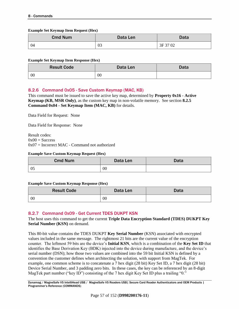
8 - Commands
Dynamag / MagneSafe V5 IntelliHead USB / MagneSafe V5 Readers USB| Secure Card Reader Authenticators and OEM Products |
Programmer’s Reference (COMMANDS)
Page 57 of 152 (D998200176-11)
Example Set Keymap Item Request (Hex)
Cmd Num Data Len Data
04 03 3F 37 02
Example Set Keymap Item Response (Hex)
Result Code Data Len Data
00 00
8.2.6 Command 0x05 - Save Custom Keymap (MAC, KB)
This command must be issued to save the active key map, determined by Property 0x16 - Active
Keymap (KB, MSR Only), as the custom key map in non-volatile memory. See section 8.2.5
Command 0x04 - Set Keymap Item (MAC, KB) for details.
Data Field for Request: None
Data Field for Response: None
Result codes:
0x00 = Success
0x07 = Incorrect MAC - Command not authorized
Example Save Custom Keymap Request (Hex)
Cmd Num Data Len Data
05 00
Example Save Custom Keymap Response (Hex)
Result Code Data Len Data
00 00
8.2.7 Command 0x09 - Get Current TDES DUKPT KSN
The host uses this command to get the current Triple Data Encryption Standard (TDES) DUKPT Key
Serial Number (KSN) on demand.
This 80-bit value contains the TDES DUKPT Key Serial Number (KSN) associated with encrypted
values included in the same message. The rightmost 21 bits are the current value of the encryption
counter. The leftmost 59 bits are the device’s Initial KSN, which is a combination of the Key Set ID that
identifies the Base Derivation Key (BDK) injected into the device during manufacture, and the device’s
serial number (DSN); how those two values are combined into the 59 bit Initial KSN is defined by a
convention the customer defines when architecting the solution, with support from MagTek. For
example, one common scheme is to concatenate a 7 hex digit (28 bit) Key Set ID, a 7 hex digit (28 bit)
Device Serial Number, and 3 padding zero bits. In these cases, the key can be referenced by an 8-digit
MagTek part number (“key ID”) consisting of the 7 hex digit Key Set ID plus a trailing “0.”
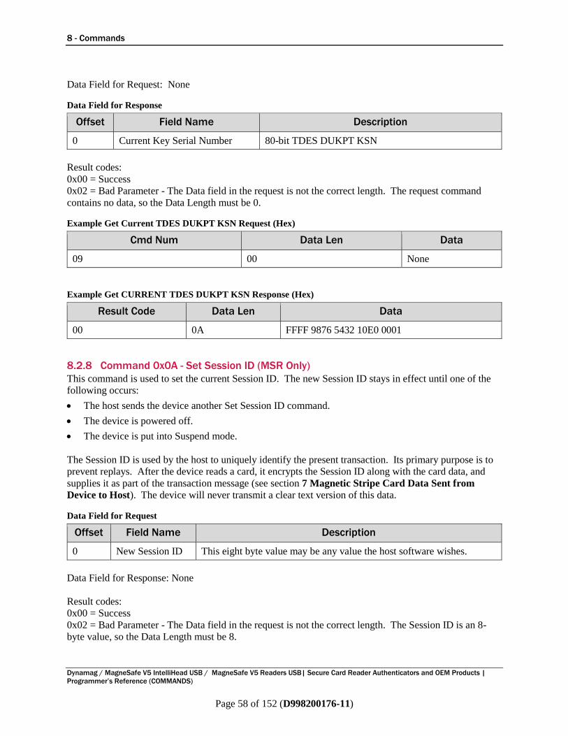
8 - Commands
Dynamag / MagneSafe V5 IntelliHead USB / MagneSafe V5 Readers USB| Secure Card Reader Authenticators and OEM Products |
Programmer’s Reference (COMMANDS)
Page 58 of 152 (D998200176-11)
Data Field for Request: None
Data Field for Response
Offset Field Name Description
0 Current Key Serial Number 80-bit TDES DUKPT KSN
Result codes:
0x00 = Success
0x02 = Bad Parameter - The Data field in the request is not the correct length. The request command
contains no data, so the Data Length must be 0.
Example Get Current TDES DUKPT KSN Request (Hex)
Cmd Num Data Len Data
09 00 None
Example Get CURRENT TDES DUKPT KSN Response (Hex)
Result Code Data Len Data
00 0A FFFF 9876 5432 10E0 0001
8.2.8 Command 0x0A - Set Session ID (MSR Only)
This command is used to set the current Session ID. The new Session ID stays in effect until one of the
following occurs:
The host sends the device another Set Session ID command.
The device is powered off.
The device is put into Suspend mode.
The Session ID is used by the host to uniquely identify the present transaction. Its primary purpose is to
prevent replays. After the device reads a card, it encrypts the Session ID along with the card data, and
supplies it as part of the transaction message (see section 7 Magnetic Stripe Card Data Sent from
Device to Host). The device will never transmit a clear text version of this data.
Data Field for Request
Offset Field Name Description
0 New Session ID This eight byte value may be any value the host software wishes.
Data Field for Response: None
Result codes:
0x00 = Success
0x02 = Bad Parameter - The Data field in the request is not the correct length. The Session ID is an 8-
byte value, so the Data Length must be 8.
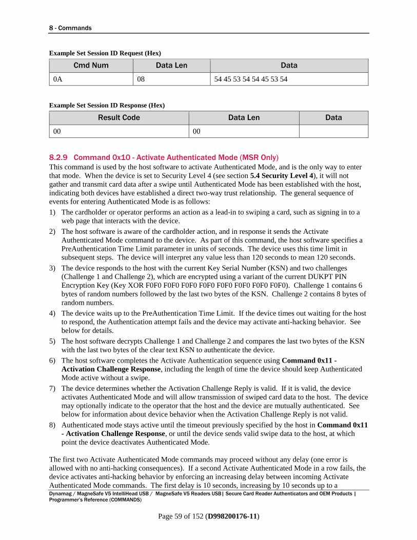
8 - Commands
Dynamag / MagneSafe V5 IntelliHead USB / MagneSafe V5 Readers USB| Secure Card Reader Authenticators and OEM Products |
Programmer’s Reference (COMMANDS)
Page 59 of 152 (D998200176-11)
Example Set Session ID Request (Hex)
Cmd Num Data Len Data
0A 08 54 45 53 54 54 45 53 54
Example Set Session ID Response (Hex)
Result Code Data Len Data
00 00
8.2.9 Command 0x10 - Activate Authenticated Mode (MSR Only)
This command is used by the host software to activate Authenticated Mode, and is the only way to enter
that mode. When the device is set to Security Level 4 (see section 5.4 Security Level 4), it will not
gather and transmit card data after a swipe until Authenticated Mode has been established with the host,
indicating both devices have established a direct two-way trust relationship. The general sequence of
events for entering Authenticated Mode is as follows:
1) The cardholder or operator performs an action as a lead-in to swiping a card, such as signing in to a
web page that interacts with the device.
2) The host software is aware of the cardholder action, and in response it sends the Activate
Authenticated Mode command to the device. As part of this command, the host software specifies a
PreAuthentication Time Limit parameter in units of seconds. The device uses this time limit in
subsequent steps. The device will interpret any value less than 120 seconds to mean 120 seconds.
3) The device responds to the host with the current Key Serial Number (KSN) and two challenges
(Challenge 1 and Challenge 2), which are encrypted using a variant of the current DUKPT PIN
Encryption Key (Key XOR F0F0 F0F0 F0F0 F0F0 F0F0 F0F0 F0F0 F0F0). Challenge 1 contains 6
bytes of random numbers followed by the last two bytes of the KSN. Challenge 2 contains 8 bytes of
random numbers.
4) The device waits up to the PreAuthentication Time Limit. If the device times out waiting for the host
to respond, the Authentication attempt fails and the device may activate anti-hacking behavior. See
below for details.
5) The host software decrypts Challenge 1 and Challenge 2 and compares the last two bytes of the KSN
with the last two bytes of the clear text KSN to authenticate the device.
6) The host software completes the Activate Authentication sequence using Command 0x11 -
Activation Challenge Response, including the length of time the device should keep Authenticated
Mode active without a swipe.
7) The device determines whether the Activation Challenge Reply is valid. If it is valid, the device
activates Authenticated Mode and will allow transmission of swiped card data to the host. The device
may optionally indicate to the operator that the host and the device are mutually authenticated. See
below for information about device behavior when the Activation Challenge Reply is not valid.
8) Authenticated mode stays active until the timeout previously specified by the host in Command 0x11
- Activation Challenge Response, or until the device sends valid swipe data to the host, at which
point the device deactivates Authenticated Mode.
The first two Activate Authenticated Mode commands may proceed without any delay (one error is
allowed with no anti-hacking consequences). If a second Activate Authenticated Mode in a row fails, the
device activates anti-hacking behavior by enforcing an increasing delay between incoming Activate
Authenticated Mode commands. The first delay is 10 seconds, increasing by 10 seconds up to a

8 - Commands
Dynamag / MagneSafe V5 IntelliHead USB / MagneSafe V5 Readers USB| Secure Card Reader Authenticators and OEM Products |
Programmer’s Reference (COMMANDS)
Page 60 of 152 (D998200176-11)
maximum delay of 10 minutes. The operator may deactivate anti-hacking mode at any time by swiping
any encoded magnetic stripe card. When the device is in this anti-hacking mode, it will not respond to
Command 0x02 - Reset Device.
To support use of Authenticated Mode, the host software can use Command 0x14 - Get Device State
(MSR Only) at any time to determine the current state of the device.
Data Field for Request
Offset Field Name Description
0 PreAuthentication Time
Limit (msb)
Most significant byte of the PreAuthentication Time Limit in
seconds (120 seconds or greater)
1 PreAuthentication Time
Limit (lsb)
Least significant byte of the PreAuthentication Time Limit in
seconds (120 seconds or greater)
Data Field for Response
Offset Field Name Description
0 Current Key
Serial Number
This eighty-bit value includes the Initial Key Serial Number in the
leftmost 59 bits and the value of the encryption counter in the rightmost
21 bits.
10 Challenge 1 The host should use this eight-byte challenge later in Command 0x11 -
Activation Challenge Response, and to authenticate the device.
18 Challenge 2 The host should use this eight-byte challenge later in Command 0x12 -
Deactivate Authenticated Mode.
Result codes:
0x00 = Success
0x03 = Redundant - the device is already in this mode
0x05 = Delayed - the request is refused due to anti-hacking mode
0x07 = Sequence Error - the current Security Level is too low
0x80 = Encryption Counter Expired
Example Activate Authenticated Mode Request (Hex)
Cmd Num Data Len Data
10 00
Example Activate Authenticated Mode Response (Hex)
Result Code Data Len Data
00 1A FFFF 0123 4567 8000 0003 9845 A48B 7ED3 C294 7987 5FD4 03FA
8543
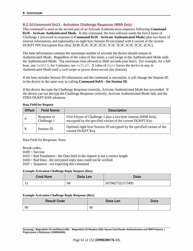
8 - Commands
Dynamag / MagneSafe V5 IntelliHead USB / MagneSafe V5 Readers USB| Secure Card Reader Authenticators and OEM Products |
Programmer’s Reference (COMMANDS)
Page 61 of 152 (D998200176-11)
8.2.10 Command 0x11 - Activation Challenge Response (MSR Only)
This command is used as the second part of an Activate Authentication sequence following Command
0x10 - Activate Authenticated Mode. In this command, the host software sends the first 6 bytes of
Challenge 1 (received in response to Command 0x10 - Activate Authenticated Mode) plus two bytes of
timeout information, and (optionally) an eight byte Session ID encrypted with a variant of the current
DUKPT PIN Encryption Key (Key XOR 3C3C 3C3C 3C3C 3C3C 3C3C 3C3C 3C3C 3C3C).
The time information contains the maximum number of seconds the device should remain in
Authenticated Mode. Regardless of the value of this timer, a card swipe in the Authenticated Mode ends
the Authenticated Mode. The maximum time allowed is 3600 seconds (one hour). For example, for a full
hour, use 0x0E10; for 3 minutes, use 0x012C. A value of 0x00 forces the device to stay in
Authenticated Mode until a card swipe or power down occurs (no timeout).
If the host includes Session ID information and the command is successful, it will change the Session ID
in the device in the same way as calling Command 0x0A - Set Session ID.
If the device decrypts the Challenge Response correctly, Activate Authenticated Mode has succeeded. If
the device can not decrypt the Challenge Response correctly, Activate Authenticated Mode fails and the
TDES DUKPT KSN advances.
Data Field for Request
Offset Field Name Description
0 Response to
Challenge 1
First 6 bytes of Challenge 1 plus a two-byte timeout (MSB first),
encrypted by the specified variant of the current DUKPT Key.
8 Session ID Optional eight byte Session ID encrypted by the specified variant of the
current DUKPT Key.
Data Field for Response: None
Result codes:
0x00 = Success
0x02 = Bad Parameters - the Data field in the request is not a correct length
0x04 = Bad Data - the encrypted reply data could not be verified
0x07 = Sequence - not expecting this command
Example Activation Challenge Reply Request (Hex)
Cmd Num Data Len Data
11 08 8579827521573495
Example Activation Challenge Reply Response (Hex)
Result Code Data Len Data
00 00
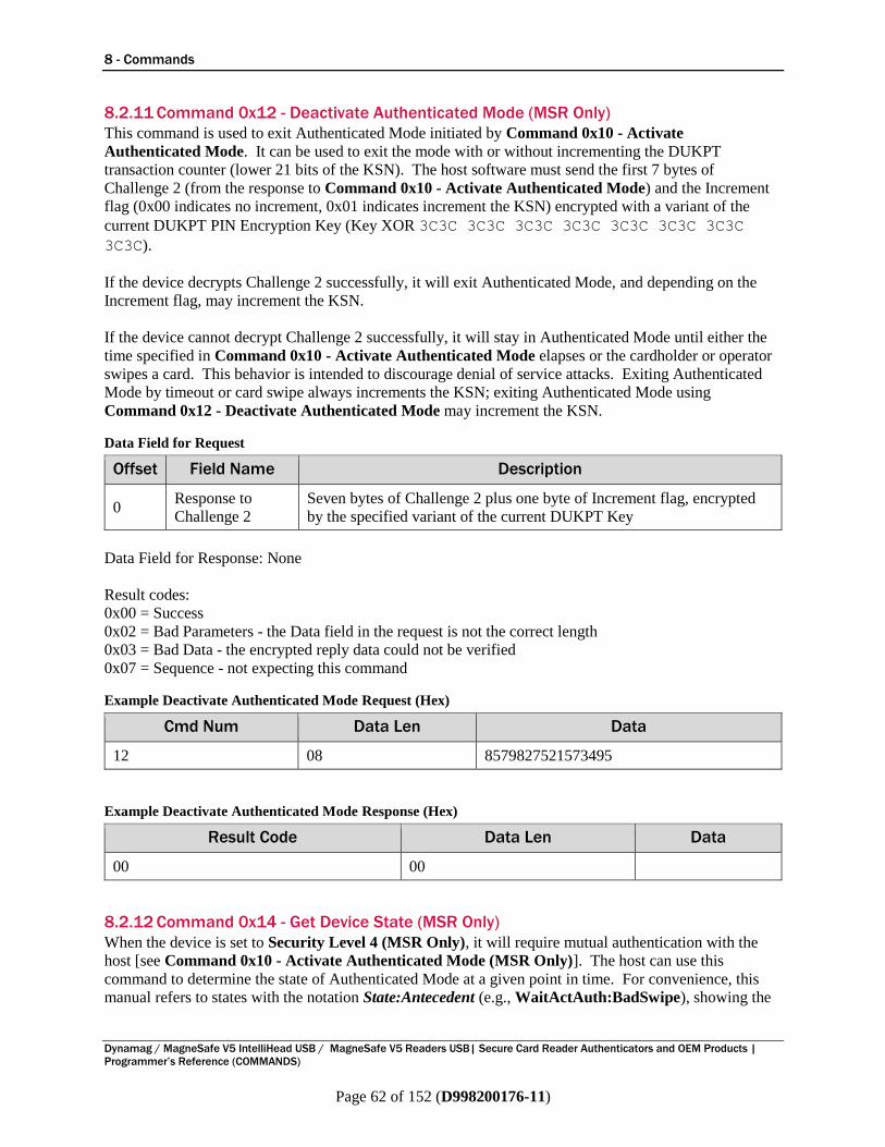
8 - Commands
Dynamag / MagneSafe V5 IntelliHead USB / MagneSafe V5 Readers USB| Secure Card Reader Authenticators and OEM Products |
Programmer’s Reference (COMMANDS)
Page 62 of 152 (D998200176-11)
8.2.11 Command 0x12 - Deactivate Authenticated Mode (MSR Only)
This command is used to exit Authenticated Mode initiated by Command 0x10 - Activate
Authenticated Mode. It can be used to exit the mode with or without incrementing the DUKPT
transaction counter (lower 21 bits of the KSN). The host software must send the first 7 bytes of
Challenge 2 (from the response to Command 0x10 - Activate Authenticated Mode) and the Increment
flag (0x00 indicates no increment, 0x01 indicates increment the KSN) encrypted with a variant of the
current DUKPT PIN Encryption Key (Key XOR 3C3C 3C3C 3C3C 3C3C 3C3C 3C3C 3C3C
3C3C).
If the device decrypts Challenge 2 successfully, it will exit Authenticated Mode, and depending on the
Increment flag, may increment the KSN.
If the device cannot decrypt Challenge 2 successfully, it will stay in Authenticated Mode until either the
time specified in Command 0x10 - Activate Authenticated Mode elapses or the cardholder or operator
swipes a card. This behavior is intended to discourage denial of service attacks. Exiting Authenticated
Mode by timeout or card swipe always increments the KSN; exiting Authenticated Mode using
Command 0x12 - Deactivate Authenticated Mode may increment the KSN.
Data Field for Request
Offset Field Name Description
0 Response to
Challenge 2
Seven bytes of Challenge 2 plus one byte of Increment flag, encrypted
by the specified variant of the current DUKPT Key
Data Field for Response: None
Result codes:
0x00 = Success
0x02 = Bad Parameters - the Data field in the request is not the correct length
0x03 = Bad Data - the encrypted reply data could not be verified
0x07 = Sequence - not expecting this command
Example Deactivate Authenticated Mode Request (Hex)
Cmd Num Data Len Data
12 08 8579827521573495
Example Deactivate Authenticated Mode Response (Hex)
Result Code Data Len Data
00 00
8.2.12 Command 0x14 - Get Device State (MSR Only)
When the device is set to Security Level 4 (MSR Only), it will require mutual authentication with the
host [see Command 0x10 - Activate Authenticated Mode (MSR Only)]. The host can use this
command to determine the state of Authenticated Mode at a given point in time. For convenience, this
manual refers to states with the notation State:Antecedent (e.g., WaitActAuth:BadSwipe), showing the

8 - Commands
Dynamag / MagneSafe V5 IntelliHead USB / MagneSafe V5 Readers USB| Secure Card Reader Authenticators and OEM Products |
Programmer’s Reference (COMMANDS)
Page 63 of 152 (D998200176-11)
current state and the state that led to it. Lists of possible states and their definitions are provided in the
device response tables below.
In most cases, the host software can also track the state of Authenticated Mode by inference. As the host
software interacts with the device, most state transitions are marked by the messages exchanged with the
device. The exception is the transition from WaitActRply:x to WaitActAuth:TOAuth, which happens
if the device times out waiting for the host to send Command 0x11 - Activation Challenge Response
(MSR Only), which the device does not report to the host. To cover this case, the host must be aware
that a timeout could occur, in which case the device will respond to Command 0x11 - Activation
Challenge Response (MSR Only) with Result Code 0x07 (Sequence Error).
Example 1 – Power Up followed by Authentication and good swipe:
1) Device powers on. Host software should send this command to discover the current state of the
device is WaitActAuth:PU.
2) Host sends a valid Command 0x10 - Activate Authenticated Mode (MSR Only). Device responds
with result code 0x00, inferring the transition to the WaitActRply:PU state.
3) Host sends a valid Command 0x11 - Activation Challenge Response (MSR Only). Device
responds with result code 0x00, inferring the transition to the WaitSwipe:PU state.
4) Cardholder swipes a card correctly. Device sends card data to the host, inferring the transition to the
WaitActAuth:GoodSwipe state.
Example 2 – Device times out waiting for swipe:
1) Device waiting after a good swipe. Host software may send this command to discover the current
state of the device is WaitActAuth:GoodSwipe.
2) Host sends valid Command 0x10 - Activate Authenticated Mode (MSR Only). Device responds
with result code 0x00, inferring the transition to the WaitActRply:GoodSwipe state.
3) Host sends a valid Command 0x11 - Activation Challenge Response (MSR Only). Device
responds with result code 0x00, inferring the transition to the WaitSwipe:GoodSwipe state.
4) Authenticated mode times out before a swipe occurs. Device sends mostly empty card data to the
host to report the timeout in Device Encryption Status. The host infers the transition to the
WaitActAuth:TOSwipe state.
Example 3 – Host sends invalid Command 0x11 - Activation Challenge Response (MSR Only):
1) Device waiting after a good swipe. Host software may send this command to discover the current
state of the device is WaitActAuth:GoodSwipe.
2) Host sends valid Command 0x10 - Activate Authenticated Mode (MSR Only). Device responds
with result code 0x00, inferring the transition to the WaitActRply:GoodSwipe state.
3) Host sends invalid Command 0x11 - Activation Challenge Response (MSR Only). Device
responds with result code 0x02 or 0x04, inferring the transition to the WaitActAuth:FailAuth state.
Example 4 – Host waits too long sending Command 0x11 - Activation Challenge Response (MSR
Only):
1) Device waiting after a good swipe. Host software may send this command to discover the current
state of the device is WaitActAuth:GoodSwipe.
2) Host sends valid Command 0x10 - Activate Authenticated Mode (MSR Only). Device responds
with result code 0x00, inferring the transition to the WaitActRply:GoodSwipe state.

8 - Commands
Dynamag / MagneSafe V5 IntelliHead USB / MagneSafe V5 Readers USB| Secure Card Reader Authenticators and OEM Products |
Programmer’s Reference (COMMANDS)
Page 64 of 152 (D998200176-11)
3) Device times out waiting for host to send Command 0x11 - Activation Challenge Response (MSR
Only) (State => WaitActAuth:TOAuth). Host doesn’t know because the device does not send any
message.
4) Host eventually sends Command 0x11 - Activation Challenge Response (MSR Only) (State
remains WaitActAuth:TOAuth). Device responds with result code 0x07, inferring the previous
transition to WaitActAuth:TOAuth state.
Data Field for Request: None
Data Field for Response First Byte – Current State
Current Device State
Value Name Meaning
0x00 WaitActAuth
Waiting for Activate Authenticated Mode. The device requires the host to
authenticate using Command 0x10 - Activate Authenticated Mode before
it will accept swipes.
0x01 WaitActRply
Waiting for Activation Challenge Reply. The host has started to
authenticate, and the device is waiting for Command 0x11 - Activation
Challenge Response.
0x02 WaitSwipe Waiting for swipe. The device is waiting for the cardholder or operator to
swipe a card.
0x03 WaitDelay
Waiting for Anti-Hacking Timer. Two or more previous attempts to
Authenticate have failed; the device is waiting for the Anti-Hacking timer to
expire before it accepts Command 0x10 - Activate Authenticated Mode.
Data Field for Response Second Byte - How the device got to its current state
Current State Antecedent
Value Name Meaning
0x00 PU Just Powered Up. The device has had no swipes and has not been
Authenticated since it was powered up.
0x01 GoodAuth Authentication Activation Successful. The host has sent the device a valid
Command 0x11 - Activation Challenge Response.
0x02 GoodSwipe Good Swipe. The cardholder swiped a valid card correctly.
0x03 BadSwipe Bad Swipe. The cardholder swiped a card incorrectly or the card is not
valid.
0x04 FailAuth Authentication Activation Failed. The most recent Command 0x11 -
Activation Challenge Response failed.
0x05 FailDeact Authentication Deactivation Failed. A recent Command 0x12 - Deactivate
Authenticated Mode failed.
0x06 TOAuth
Authentication Activation Timed Out. The host failed to send Command
0x11 - Activation Challenge Response in the time period specified by
Command 0x10 - Activate Authenticated Mode.
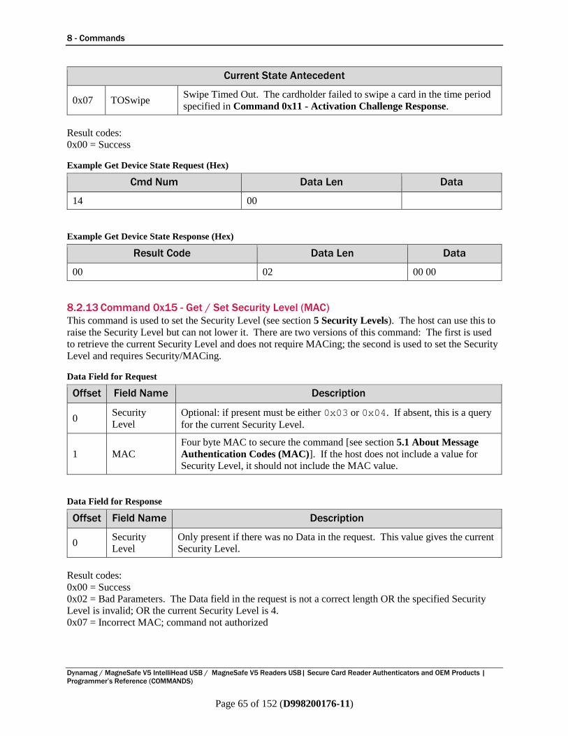
8 - Commands
Dynamag / MagneSafe V5 IntelliHead USB / MagneSafe V5 Readers USB| Secure Card Reader Authenticators and OEM Products |
Programmer’s Reference (COMMANDS)
Page 65 of 152 (D998200176-11)
Current State Antecedent
0x07 TOSwipe Swipe Timed Out. The cardholder failed to swipe a card in the time period
specified in Command 0x11 - Activation Challenge Response.
Result codes:
0x00 = Success
Example Get Device State Request (Hex)
Cmd Num Data Len Data
14 00
Example Get Device State Response (Hex)
Result Code Data Len Data
00 02 00 00
8.2.13 Command 0x15 - Get / Set Security Level (MAC)
This command is used to set the Security Level (see section 5 Security Levels). The host can use this to
raise the Security Level but can not lower it. There are two versions of this command: The first is used
to retrieve the current Security Level and does not require MACing; the second is used to set the Security
Level and requires Security/MACing.
Data Field for Request
Offset Field Name Description
0 Security
Level
Optional: if present must be either 0x03 or 0x04. If absent, this is a query
for the current Security Level.
1 MAC
Four byte MAC to secure the command [see section 5.1 About Message
Authentication Codes (MAC)]. If the host does not include a value for
Security Level, it should not include the MAC value.
Data Field for Response
Offset Field Name Description
0 Security
Level
Only present if there was no Data in the request. This value gives the current
Security Level.
Result codes:
0x00 = Success
0x02 = Bad Parameters. The Data field in the request is not a correct length OR the specified Security
Level is invalid; OR the current Security Level is 4.
0x07 = Incorrect MAC; command not authorized

8 - Commands
Dynamag / MagneSafe V5 IntelliHead USB / MagneSafe V5 Readers USB| Secure Card Reader Authenticators and OEM Products |
Programmer’s Reference (COMMANDS)
Page 66 of 152 (D998200176-11)
Example Set Security Level to 3 Request (Hex)
Cmd Num Data Len Data
15 05 03 xx xx xx xx
Where xx xx xx xx is a valid MAC
Example Set Security Level Response (Hex)
Result Code Data Len Data
00 00
Example Get Security Level Request (Hex)
Cmd Num Data Len Data
15 00
Example Get Security Level Response (Hex)
Result Code Data Len Data
00 01 03
8.2.14 Command 0x1C - Get Remaining MSR Transactions Counter (MSR Only)
This command is used to get the maximum number of remaining card swipe transactions or correctly
completed Authentication sequences (Command 0x10 - Activate Authenticated Mode followed by a
correct Command 0x11 - Activation Challenge Response) that the device can process. The value it
returns is also sometimes referred to as the transaction threshold.
The value has three possible states:
Disabled - value 0xFFFFFF - In this state there is no limit to the number of transactions that can be
performed.
Expired - value 0x000000 - This state indicates MSR transactions and Authentication commands are
prohibited.
Active - value 1 to 1,000,000 (0x000001 to 0x0F4240) - In this state, each transaction or successful
Authentication sequence causes the value to be decremented and allows transactions to be processed.
If an Authentication sequence decrements this value to 0, the device will permit one final encrypted
card swipe.
Some devices are configured to only allow the manufacturer to call this command.
Data Field for Request: None

8 - Commands
Dynamag / MagneSafe V5 IntelliHead USB / MagneSafe V5 Readers USB| Secure Card Reader Authenticators and OEM Products |
Programmer’s Reference (COMMANDS)
Page 67 of 152 (D998200176-11)
Data Field for Response
Offset Field Name Description
0 Device Serial
Number
16 bytes of device serial number. If the serial number is shorter than
15 bytes, this value will be left justified and padded with binary zeroes.
At least one byte (usually the last one) must contain binary zero.
16 Remaining MSR
Transactions
This three byte value contains the current number of remaining MSR
transactions.
Result codes:
0x00 = Success
0x02 = Invalid length
Example Get Remaining MSR Transactions Request (Hex)
Cmd Num Data Len Data
1C 00
Example Get Remaining MSR Transactions Response (Hex) - 2033 MSR Transactions Remaining
Result Code Data Len Data
00 13 54455354205345545550203030303100
0007F1
8.2.15 Command 0x30 - Encrypt Bulk Data (Encrypt Bulk Data Only)
The host can use this command to encrypt a block of data. The device uses the Data-Response variant of
the DUKPT key to encrypt the data. The command will also compute a MAC for the S/N, Num Bytes
Encrypted, KSN, and Cryptogram. Data to be encrypted that is not a multiple of 8 bytes will be padded
with NULLs to be a multiple of 8.
The device will increment the DUKPT key counter/pointer before processing this command.
Some devices are configured to only allow the manufacturer to call this command.
Example Encrypt Bulk Data Request (Hex)
Cmd Num Data Len Data
30 05 01 02 03 04 05
Example Encrypt Bulk Data Response (Hex)
Result
Code
Data
Len
DSN (16
bytes)
Num Bytes
Encrypted
(1 byte)
KSN
(10 bytes)
Cryptogram (8
bytes)
MAC
(4
bytes)
00 0x27 32 31 30 34
32 38 31 32 05
31 32 33 34 35
31 32 33 34 35
01 02 03 04
05 06 07 08
01 02
03 04
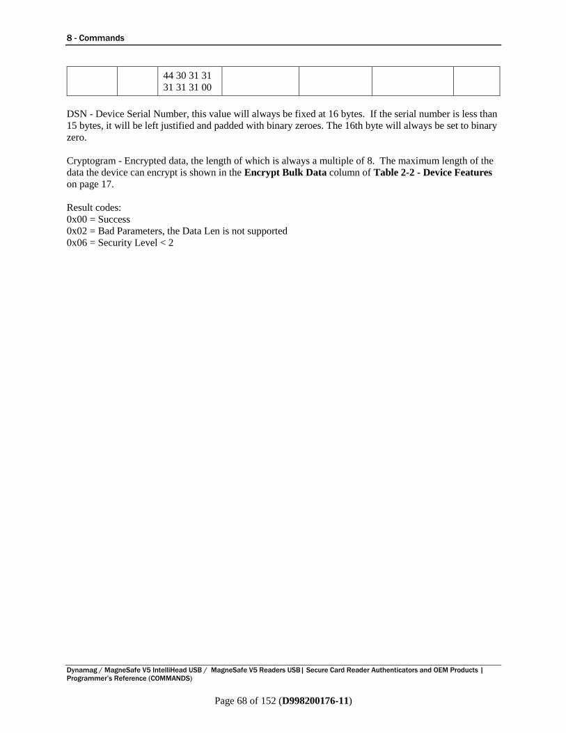
8 - Commands
Dynamag / MagneSafe V5 IntelliHead USB / MagneSafe V5 Readers USB| Secure Card Reader Authenticators and OEM Products |
Programmer’s Reference (COMMANDS)
Page 68 of 152 (D998200176-11)
DSN - Device Serial Number, this value will always be fixed at 16 bytes. If the serial number is less than
15 bytes, it will be left justified and padded with binary zeroes. The 16th byte will always be set to binary
zero.
Cryptogram - Encrypted data, the length of which is always a multiple of 8. The maximum length of the
data the device can encrypt is shown in the Encrypt Bulk Data column of Table 2-2 - Device Features
on page 17.
Result codes:
0x00 = Success
0x02 = Bad Parameters, the Data Len is not supported
0x06 = Security Level < 2
44 30 31 31
31 31 31 00

9 - Properties
Dynamag / MagneSafe V5 IntelliHead USB / MagneSafe V5 Readers USB| Secure Card Reader Authenticators and OEM Products |
Programmer’s Reference (COMMANDS)
Page 69 of 152 (D998200176-11)
9 Properties MagneSafe V5 devices have a number of programmable configuration properties stored in non-volatile
memory. Most of the programmable properties pertain to data formats other than vendor-defined HID,
but some of the properties deal with the device regardless of format (for information about changing
formats and making format-specific properties visible, see Property 0x10 - Interface Type). These
properties can be configured at the factory or by an administrator using a program supplied by MagTek.
Changing these configuration properties requires low-level communication with the device. Details for
communicating with the device to read or change programmable properties are provided in section 8.2.1
Command 0x00 - Get Property and section 8.2.2 Command 0x01 - Set Property (MAC).
9.1 Property 0x00 - Firmware ID Property ID: 0x00
Property Type: String
Length: Fixed at 11 bytes
Get Property: Yes
Set Property: No
Default Value: Part number of installed firmware
This is an 11 or 13 byte read-only property that identifies the firmware part number and revision installed
on the device. The first 8 or 10 bytes represent the part number, the next byte represents the firmware
major revision number, and the final two bytes represent an internal build number. For example, this
property might be “21042812D01”.
Example Get Firmware ID property Request (Hex)
Cmd Num Data Len Property ID
00 01 00
Example Get Firmware ID property Response (Hex)
Result Code Data Len Property Value
00 0B 32 31 30 34 32 38 31 32 44 30 31
9.2 Property 0x01 - USB Serial Number (HID, KB) Property ID: 0x01
Property Type: String
Length: 0 - 15 bytes
Get Property: Yes
Set Property: Yes
Default Value: Null string / Packed hexadecimal device serial number set when the device is configured.
The value contains the USB serial number, from 0 to 15 bytes long. The device will send the value of this
property (if any) to the host during USB device enumeration. This is useful for distinguishing between
devices when more than one of the same kind of device is attached to the host.
This property is stored in non-volatile memory, so it will persist when the device is power cycled. When
this property is changed, the device must be reset (see Command 0x02 - Reset Device) or powered off
for at least 30 seconds, then powered on, before the changes will take effect.
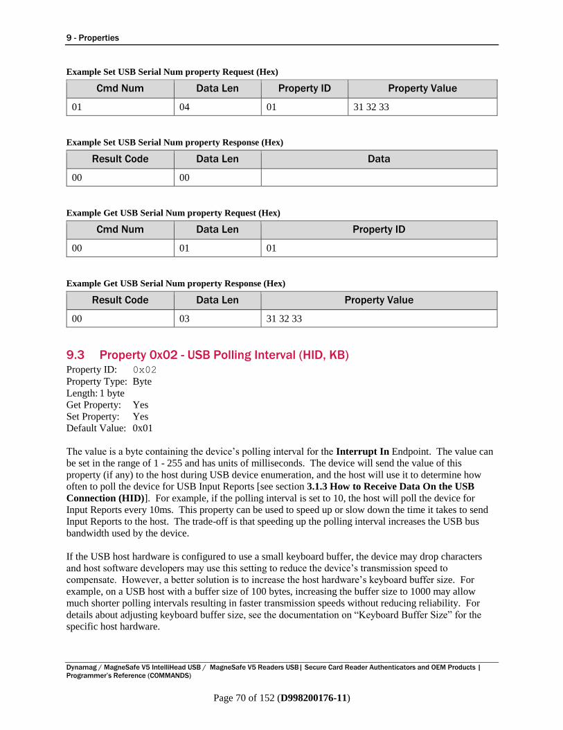
9 - Properties
Dynamag / MagneSafe V5 IntelliHead USB / MagneSafe V5 Readers USB| Secure Card Reader Authenticators and OEM Products |
Programmer’s Reference (COMMANDS)
Page 70 of 152 (D998200176-11)
Example Set USB Serial Num property Request (Hex)
Cmd Num Data Len Property ID Property Value
01 04 01 31 32 33
Example Set USB Serial Num property Response (Hex)
Result Code Data Len Data
00 00
Example Get USB Serial Num property Request (Hex)
Cmd Num Data Len Property ID
00 01 01
Example Get USB Serial Num property Response (Hex)
Result Code Data Len Property Value
00 03 31 32 33
9.3 Property 0x02 - USB Polling Interval (HID, KB) Property ID: 0x02
Property Type: Byte
Length: 1 byte
Get Property: Yes
Set Property: Yes
Default Value: 0x01
The value is a byte containing the device’s polling interval for the Interrupt In Endpoint. The value can
be set in the range of 1 - 255 and has units of milliseconds. The device will send the value of this
property (if any) to the host during USB device enumeration, and the host will use it to determine how
often to poll the device for USB Input Reports [see section 3.1.3 How to Receive Data On the USB
Connection (HID)]. For example, if the polling interval is set to 10, the host will poll the device for
Input Reports every 10ms. This property can be used to speed up or slow down the time it takes to send
Input Reports to the host. The trade-off is that speeding up the polling interval increases the USB bus
bandwidth used by the device.
If the USB host hardware is configured to use a small keyboard buffer, the device may drop characters
and host software developers may use this setting to reduce the device’s transmission speed to
compensate. However, a better solution is to increase the host hardware’s keyboard buffer size. For
example, on a USB host with a buffer size of 100 bytes, increasing the buffer size to 1000 may allow
much shorter polling intervals resulting in faster transmission speeds without reducing reliability. For
details about adjusting keyboard buffer size, see the documentation on “Keyboard Buffer Size” for the
specific host hardware.
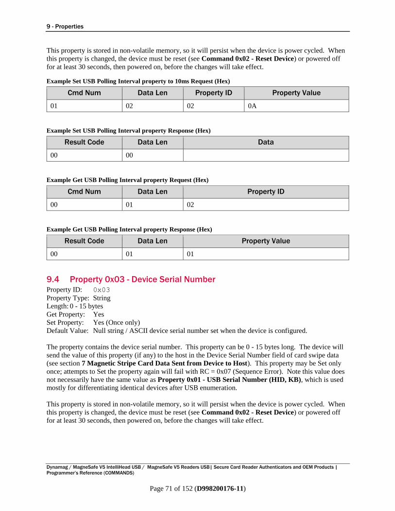
9 - Properties
Dynamag / MagneSafe V5 IntelliHead USB / MagneSafe V5 Readers USB| Secure Card Reader Authenticators and OEM Products |
Programmer’s Reference (COMMANDS)
Page 71 of 152 (D998200176-11)
This property is stored in non-volatile memory, so it will persist when the device is power cycled. When
this property is changed, the device must be reset (see Command 0x02 - Reset Device) or powered off
for at least 30 seconds, then powered on, before the changes will take effect.
Example Set USB Polling Interval property to 10ms Request (Hex)
Cmd Num Data Len Property ID Property Value
01 02 02 0A
Example Set USB Polling Interval property Response (Hex)
Result Code Data Len Data
00 00
Example Get USB Polling Interval property Request (Hex)
Cmd Num Data Len Property ID
00 01 02
Example Get USB Polling Interval property Response (Hex)
Result Code Data Len Property Value
00 01 01
9.4 Property 0x03 - Device Serial Number Property ID: 0x03
Property Type: String
Length: 0 - 15 bytes
Get Property: Yes
Set Property: Yes (Once only)
Default Value: Null string / ASCII device serial number set when the device is configured.
The property contains the device serial number. This property can be 0 - 15 bytes long. The device will
send the value of this property (if any) to the host in the Device Serial Number field of card swipe data
(see section 7 Magnetic Stripe Card Data Sent from Device to Host). This property may be Set only
once; attempts to Set the property again will fail with RC = 0x07 (Sequence Error). Note this value does
not necessarily have the same value as Property 0x01 - USB Serial Number (HID, KB), which is used
mostly for differentiating identical devices after USB enumeration.
This property is stored in non-volatile memory, so it will persist when the device is power cycled. When
this property is changed, the device must be reset (see Command 0x02 - Reset Device) or powered off
for at least 30 seconds, then powered on, before the changes will take effect.
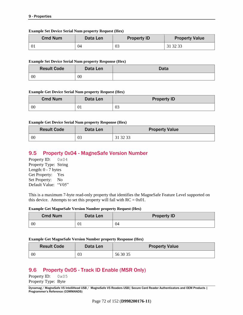
9 - Properties
Dynamag / MagneSafe V5 IntelliHead USB / MagneSafe V5 Readers USB| Secure Card Reader Authenticators and OEM Products |
Programmer’s Reference (COMMANDS)
Page 72 of 152 (D998200176-11)
Example Set Device Serial Num property Request (Hex)
Cmd Num Data Len Property ID Property Value
01 04 03 31 32 33
Example Set Device Serial Num property Response (Hex)
Result Code Data Len Data
00 00
Example Get Device Serial Num property Request (Hex)
Cmd Num Data Len Property ID
00 01 03
Example Get Device Serial Num property Response (Hex)
Result Code Data Len Property Value
00 03 31 32 33
9.5 Property 0x04 - MagneSafe Version Number Property ID: 0x04
Property Type: String
Length: 0 - 7 bytes
Get Property: Yes
Set Property: No
Default Value: “V05”
This is a maximum 7-byte read-only property that identifies the MagneSafe Feature Level supported on
this device. Attempts to set this property will fail with RC = 0x01.
Example Get MagneSafe Version Number property Request (Hex)
Cmd Num Data Len Property ID
00 01 04
Example Get MagneSafe Version Number property Response (Hex)
Result Code Data Len Property Value
00 03 56 30 35
9.6 Property 0x05 - Track ID Enable (MSR Only) Property ID: 0x05
Property Type: Byte
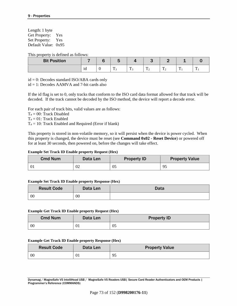
9 - Properties
Dynamag / MagneSafe V5 IntelliHead USB / MagneSafe V5 Readers USB| Secure Card Reader Authenticators and OEM Products |
Programmer’s Reference (COMMANDS)
Page 73 of 152 (D998200176-11)
Length: 1 byte
Get Property: Yes
Set Property: Yes
Default Value: 0x95
This property is defined as follows:
Bit Position 7 6 5 4 3 2 1 0
id 0 T3 T3 T2 T2 T1 T1
id = 0: Decodes standard ISO/ABA cards only
id = 1: Decodes AAMVA and 7-bit cards also
If the id flag is set to 0, only tracks that conform to the ISO card data format allowed for that track will be
decoded. If the track cannot be decoded by the ISO method, the device will report a decode error.
For each pair of track bits, valid values are as follows:
T# = 00: Track Disabled
T# = 01: Track Enabled
T# = 10: Track Enabled and Required (Error if blank)
This property is stored in non-volatile memory, so it will persist when the device is power cycled. When
this property is changed, the device must be reset (see Command 0x02 - Reset Device) or powered off
for at least 30 seconds, then powered on, before the changes will take effect.
Example Set Track ID Enable property Request (Hex)
Cmd Num Data Len Property ID Property Value
01 02 05 95
Example Set Track ID Enable property Response (Hex)
Result Code Data Len Data
00 00
Example Get Track ID Enable property Request (Hex)
Cmd Num Data Len Property ID
00 01 05
Example Get Track ID Enable property Response (Hex)
Result Code Data Len Property Value
00 01 95
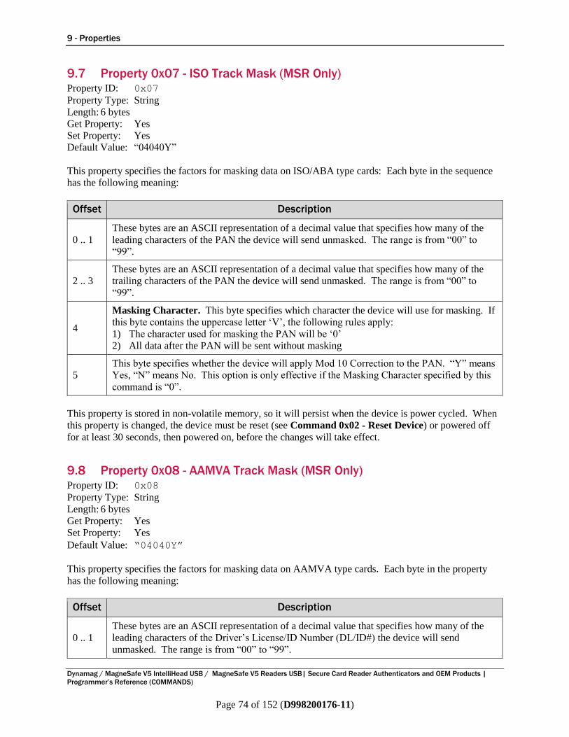
9 - Properties
Dynamag / MagneSafe V5 IntelliHead USB / MagneSafe V5 Readers USB| Secure Card Reader Authenticators and OEM Products |
Programmer’s Reference (COMMANDS)
Page 74 of 152 (D998200176-11)
9.7 Property 0x07 - ISO Track Mask (MSR Only) Property ID: 0x07
Property Type: String
Length: 6 bytes
Get Property: Yes
Set Property: Yes
Default Value: “04040Y”
This property specifies the factors for masking data on ISO/ABA type cards: Each byte in the sequence
has the following meaning:
Offset Description
0 .. 1
These bytes are an ASCII representation of a decimal value that specifies how many of the
leading characters of the PAN the device will send unmasked. The range is from “00” to
“99”.
2 .. 3
These bytes are an ASCII representation of a decimal value that specifies how many of the
trailing characters of the PAN the device will send unmasked. The range is from “00” to
“99”.
4
Masking Character. This byte specifies which character the device will use for masking. If
this byte contains the uppercase letter ‘V’, the following rules apply:
1) The character used for masking the PAN will be ‘0’
2) All data after the PAN will be sent without masking
5
This byte specifies whether the device will apply Mod 10 Correction to the PAN. “Y” means
Yes, “N” means No. This option is only effective if the Masking Character specified by this
command is “0”.
This property is stored in non-volatile memory, so it will persist when the device is power cycled. When
this property is changed, the device must be reset (see Command 0x02 - Reset Device) or powered off
for at least 30 seconds, then powered on, before the changes will take effect.
9.8 Property 0x08 - AAMVA Track Mask (MSR Only) Property ID: 0x08
Property Type: String
Length: 6 bytes
Get Property: Yes
Set Property: Yes
Default Value: “04040Y”
This property specifies the factors for masking data on AAMVA type cards. Each byte in the property
has the following meaning:
Offset Description
0 .. 1
These bytes are an ASCII representation of a decimal value that specifies how many of the
leading characters of the Driver’s License/ID Number (DL/ID#) the device will send
unmasked. The range is from “00” to “99”.

9 - Properties
Dynamag / MagneSafe V5 IntelliHead USB / MagneSafe V5 Readers USB| Secure Card Reader Authenticators and OEM Products |
Programmer’s Reference (COMMANDS)
Page 75 of 152 (D998200176-11)
Offset Description
2 .. 3 These bytes are an ASCII representation of a decimal value that specifies how many of the
trailing characters of the DL/ID# will send unmasked. The range is from “00” to “99”.
4
Masking Character. This byte specifies which character the device will use for masking. If
this byte contains the uppercase letter ‘V’, the following rules apply:
The device will mask the PAN according to the rules of this property (Property 0x34 -
Send Clear AAMVA Card Data is ignored)
The device uses ‘0’ for masking the PAN
The device will send all data after the PAN without masking
5
This byte specifies whether the device will apply Mod 10 Correction to the DL/ID#. “Y”
means Yes, “N” means No. This option is only effective if the masking character specified in
this command is “0”.
This property is stored in non-volatile memory, so it will persist when the device is power cycled. When
this property is changed, the device must be reset (see Command 0x02 - Reset Device) or powered off
for at least 30 seconds, then powered on, before the changes will take effect.
9.9 Property 0x0A - USB HID Max Packet Size (HID) Property ID: 0x0A
Property Type: Byte
Length: 1 byte
Get Property: Yes
Set Property: Yes
Default Value: 0x08
The value is a byte that contains the device’s maximum packet size for the USB Interrupt In endpoint
when using the HID data format [see section 3.1.3 How to Receive Data On the USB Connection
(HID)]. The device will send the value of this property to the host during USB device enumeration. The
value can be set in the range of 1 - 64 and has units of bytes. For example, if the maximum packet size is
set to 8, the device will send HID reports in multiple packets of 8 bytes each, possibly fewer bytes for the
last packet of the report. This property can be used to speed up or slow down the time it takes to send
data to the host. Larger packet sizes speed up communications and smaller packet sizes slow down
communications. The trade-off is that speeding up the data transfer rate increases the USB bus bandwidth
used by the device.
This property is stored in non-volatile memory, so it will persist when the device is power cycled. When
this property is changed, the device must be reset (see Command 0x02 - Reset Device) or powered off
for at least 30 seconds, then powered on, before the changes will take effect.
Example Set USB HID Max Packet Size property Request (Hex)
Cmd Num Data Len Property ID Property Value
01 02 0A 08
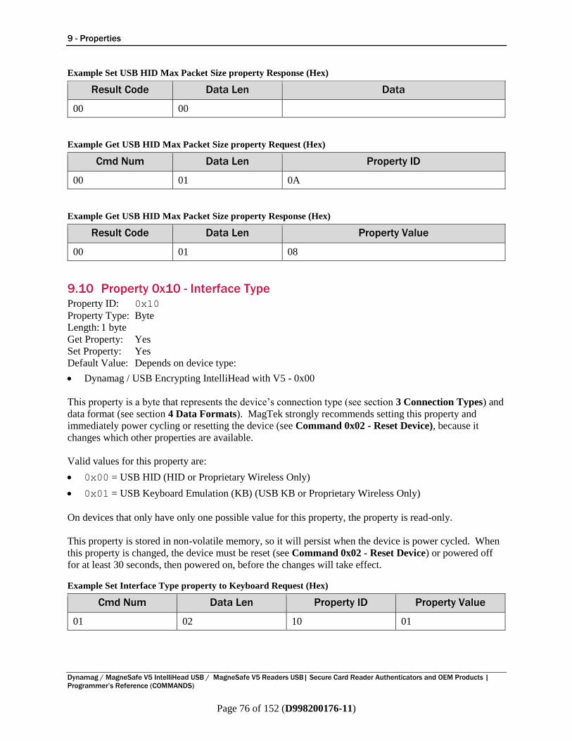
9 - Properties
Dynamag / MagneSafe V5 IntelliHead USB / MagneSafe V5 Readers USB| Secure Card Reader Authenticators and OEM Products |
Programmer’s Reference (COMMANDS)
Page 76 of 152 (D998200176-11)
Example Set USB HID Max Packet Size property Response (Hex)
Result Code Data Len Data
00 00
Example Get USB HID Max Packet Size property Request (Hex)
Cmd Num Data Len Property ID
00 01 0A
Example Get USB HID Max Packet Size property Response (Hex)
Result Code Data Len Property Value
00 01 08
9.10 Property 0x10 - Interface Type Property ID: 0x10
Property Type: Byte
Length: 1 byte
Get Property: Yes
Set Property: Yes
Default Value: Depends on device type:
Dynamag / USB Encrypting IntelliHead with V5 - 0x00
This property is a byte that represents the device’s connection type (see section 3 Connection Types) and
data format (see section 4 Data Formats). MagTek strongly recommends setting this property and
immediately power cycling or resetting the device (see Command 0x02 - Reset Device), because it
changes which other properties are available.
Valid values for this property are:
0x00 = USB HID (HID or Proprietary Wireless Only)
0x01 = USB Keyboard Emulation (KB) (USB KB or Proprietary Wireless Only)
On devices that only have only one possible value for this property, the property is read-only.
This property is stored in non-volatile memory, so it will persist when the device is power cycled. When
this property is changed, the device must be reset (see Command 0x02 - Reset Device) or powered off
for at least 30 seconds, then powered on, before the changes will take effect.
Example Set Interface Type property to Keyboard Request (Hex)
Cmd Num Data Len Property ID Property Value
01 02 10 01
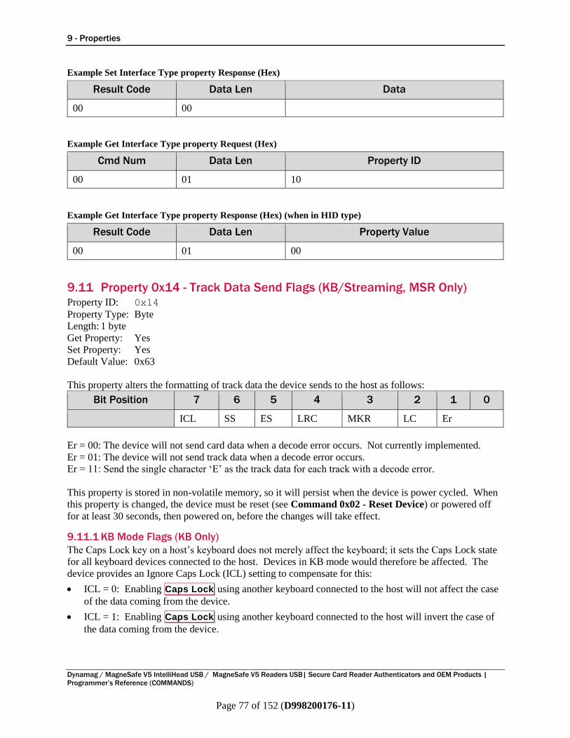
9 - Properties
Dynamag / MagneSafe V5 IntelliHead USB / MagneSafe V5 Readers USB| Secure Card Reader Authenticators and OEM Products |
Programmer’s Reference (COMMANDS)
Page 77 of 152 (D998200176-11)
Example Set Interface Type property Response (Hex)
Result Code Data Len Data
00 00
Example Get Interface Type property Request (Hex)
Cmd Num Data Len Property ID
00 01 10
Example Get Interface Type property Response (Hex) (when in HID type)
Result Code Data Len Property Value
00 01 00
9.11 Property 0x14 - Track Data Send Flags (KB/Streaming, MSR Only) Property ID: 0x14
Property Type: Byte
Length: 1 byte
Get Property: Yes
Set Property: Yes
Default Value: 0x63
This property alters the formatting of track data the device sends to the host as follows:
Bit Position 7 6 5 4 3 2 1 0
ICL SS ES LRC MKR LC Er
Er = 00: The device will not send card data when a decode error occurs. Not currently implemented.
Er = 01: The device will not send track data when a decode error occurs.
Er = 11: Send the single character ‘E’ as the track data for each track with a decode error.
This property is stored in non-volatile memory, so it will persist when the device is power cycled. When
this property is changed, the device must be reset (see Command 0x02 - Reset Device) or powered off
for at least 30 seconds, then powered on, before the changes will take effect.
9.11.1 KB Mode Flags (KB Only)
The Caps Lock key on a host’s keyboard does not merely affect the keyboard; it sets the Caps Lock state
for all keyboard devices connected to the host. Devices in KB mode would therefore be affected. The
device provides an Ignore Caps Lock (ICL) setting to compensate for this:
ICL = 0: Enabling Caps Lock using another keyboard connected to the host will not affect the case
of the data coming from the device.
ICL = 1: Enabling Caps Lock using another keyboard connected to the host will invert the case of
the data coming from the device.

9 - Properties
Dynamag / MagneSafe V5 IntelliHead USB / MagneSafe V5 Readers USB| Secure Card Reader Authenticators and OEM Products |
Programmer’s Reference (COMMANDS)
Page 78 of 152 (D998200176-11)
Minimizing key reports (MKR) means the device sends the minimum number of key reports to represent
each character. When Property 0x17 - ASCII to Keypress Conversion Type (KB, MSR Only) is set to
ACTIVE KEYMAP, the minimum number consists of one key-down report per character, except in the
case of transmitting more than one of the same character in a row. In this case, the device will send a
key-down followed by a key-up. When Property 0x17 - ASCII to Keypress Conversion Type (KB,
MSR Only) is set to ALT ASCII code, the minimum number consists of four key reports per
character (Alt and first digit down, second digit down, third digit down, Alt and third digit up). This
mode is up to two times faster, but it may not work with all host software.
When not minimizing key reports, the maximum number of key reports is sent to represent each
character. When Property 0x17 - ASCII to Keypress Conversion Type (KB, MSR Only) is set to
ACTIVE KEYMAP, the maximum number consists of two key reports per character (one for the key
down and one for the key up). When Property 0x17 - ASCII to Keypress Conversion Type (KB, MSR
Only) is set to ALT ASCII code, the maximum number consists of eight key reports per character (Alt
down, first digit down, first digit up, second digit down, second digit up, third digit down, third digit up,
Alt up). This mode is slower but it will work with all host software.
The MKR flag should be set to zero, MKR = 0: Don’t minimize key reports.
The state of the Caps Lock key on the host keyboard has no effect on the case of transmitted card data
unless the ICL bit in this property is set to 1, in which case if Caps Lock is enabled, the card data will be
transmitted opposite to what is specified by the following Lower case (LC) bit:
LC = 0: Send card data as uppercase.
LC = 1: Send card data as lowercase.
9.11.2 Streaming Flags (Streaming Only)
SS = 0: Don’t send Start Sentinel for each track.
SS = 1: Send Start Sentinel for each track.
ES = 0: Don’t send End Sentinel for each track.
ES = 1: Send End Sentinel for each track.
The LRC is the unmodified LRC from the track data. If the host software needs to verify the LRC, it
would need to restore the original Start Sentinels, then convert the track data from ASCII to card data
format, and apply the LRC calculation algorithm appropriate for the card format (e.g., ISO or AAMVA).
The LRC property only applies to track data sent in Streaming mode and completely in the clear (Security
Level 2).
LRC = 0: Don’t send LRC for each track.
LRC = 1: Send LRC for each track.
9.12 Property 0x15 - MagnePrint Flags (HID, Streaming, MSR Only) Caution: Using this command adds or suppresses fields in the data stream between the
device and host, which changes the position of all subsequent data elements in the stream.
This may render the device incompatible with host software that expects to parse a fixed
format, rather than using Property 0x2C - Format Code (Streaming, MSR Only) to determine
the position of data in the stream.
Property ID: 0x15
Property Type: Byte
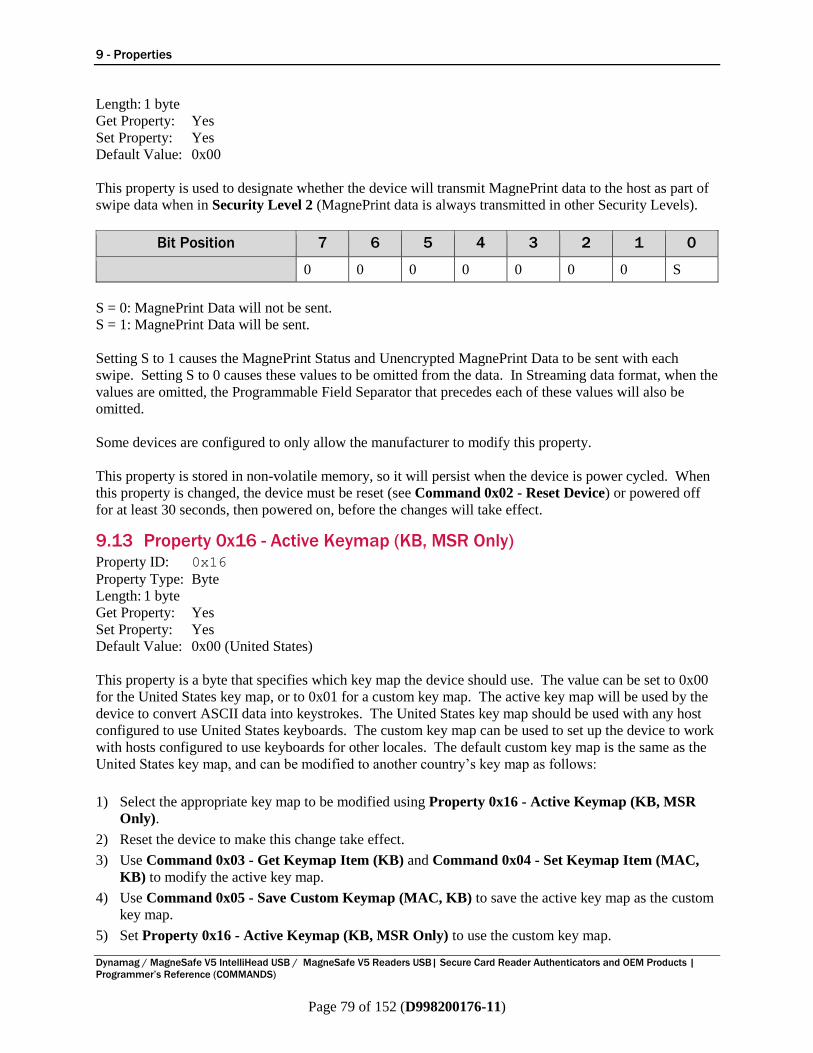
9 - Properties
Dynamag / MagneSafe V5 IntelliHead USB / MagneSafe V5 Readers USB| Secure Card Reader Authenticators and OEM Products |
Programmer’s Reference (COMMANDS)
Page 79 of 152 (D998200176-11)
Length: 1 byte
Get Property: Yes
Set Property: Yes
Default Value: 0x00
This property is used to designate whether the device will transmit MagnePrint data to the host as part of
swipe data when in Security Level 2 (MagnePrint data is always transmitted in other Security Levels).
Bit Position 7 6 5 4 3 2 1 0
0 0 0 0 0 0 0 S
S = 0: MagnePrint Data will not be sent.
S = 1: MagnePrint Data will be sent.
Setting S to 1 causes the MagnePrint Status and Unencrypted MagnePrint Data to be sent with each
swipe. Setting S to 0 causes these values to be omitted from the data. In Streaming data format, when the
values are omitted, the Programmable Field Separator that precedes each of these values will also be
omitted.
Some devices are configured to only allow the manufacturer to modify this property.
This property is stored in non-volatile memory, so it will persist when the device is power cycled. When
this property is changed, the device must be reset (see Command 0x02 - Reset Device) or powered off
for at least 30 seconds, then powered on, before the changes will take effect.
9.13 Property 0x16 - Active Keymap (KB, MSR Only) Property ID: 0x16
Property Type: Byte
Length: 1 byte
Get Property: Yes
Set Property: Yes
Default Value: 0x00 (United States)
This property is a byte that specifies which key map the device should use. The value can be set to 0x00
for the United States key map, or to 0x01 for a custom key map. The active key map will be used by the
device to convert ASCII data into keystrokes. The United States key map should be used with any host
configured to use United States keyboards. The custom key map can be used to set up the device to work
with hosts configured to use keyboards for other locales. The default custom key map is the same as the
United States key map, and can be modified to another country’s key map as follows:
1) Select the appropriate key map to be modified using Property 0x16 - Active Keymap (KB, MSR
Only).
2) Reset the device to make this change take effect.
3) Use Command 0x03 - Get Keymap Item (KB) and Command 0x04 - Set Keymap Item (MAC,
KB) to modify the active key map.
4) Use Command 0x05 - Save Custom Keymap (MAC, KB) to save the active key map as the custom
key map.
5) Set Property 0x16 - Active Keymap (KB, MSR Only) to use the custom key map.

9 - Properties
Dynamag / MagneSafe V5 IntelliHead USB / MagneSafe V5 Readers USB| Secure Card Reader Authenticators and OEM Products |
Programmer’s Reference (COMMANDS)
Page 80 of 152 (D998200176-11)
6) Reset the device to make these changes take effect.
This property is stored in non-volatile memory, so it will persist when the device is power cycled. When
this property is changed, the device must be reset (see Command 0x02 - Reset Device) or powered off
for at least 30 seconds, then powered on, before the changes will take effect.
Example Set Active Keymap property Request (Hex)
Cmd Num Data Len Property ID Property Value
01 02 16 00
Example Set Active Keymap property Response (Hex)
Result Code Data Len Data
00 00
Example Get Active Keymap property Request (Hex)
Cmd Num Data Len Property ID
00 01 16
Example Get Active Keymap property Response (Hex)
Result Code Data Len Property Value
00 01 00
9.14 Property 0x17 - ASCII to Keypress Conversion Type (KB, MSR Only) Property ID: 0x17
Property Type: Byte
Length: 1 byte
Get Property: Yes
Set Property: Yes
Default Value: 0x00 (keymap)
This property is a byte that specifies the type of conversion the device will perform when converting
ASCII data to keystrokes. The value can be set to 0x00 for keymap [the active keymap is set with
Property 0x16 - Active Keymap (KB, MSR Only)] or to 0x01 for ALT ASCII code (international
keyboard emulation).
When the value is set to 0x00 (keymap), data is transmitted to the host according to the active keymap,
which defaults to the United States keyboard keymap. For example, to transmit the ASCII character ‘?’
(063 decimal), the character is looked up in a keymap. For a United States keyboard keymap, the ‘/’
(forward slash) key combined with the left shift key modifier are stored in the keymap to represent the
key press combination that is used to represent the ASCII character ‘?’ (063 decimal).

9 - Properties
Dynamag / MagneSafe V5 IntelliHead USB / MagneSafe V5 Readers USB| Secure Card Reader Authenticators and OEM Products |
Programmer’s Reference (COMMANDS)
Page 81 of 152 (D998200176-11)
When the value is set to 0x01 (ALT ASCII code), instead of using the key map, the device transmits
an international keyboard key press combination consisting of the decimal values of the ASCII character
combined with the ALT key modifier. For example, to transmit the ASCII character ‘?’ (063 decimal),
the device sends keypad ‘0’ combined with left ALT key modifier, keypad ‘6’ combined with the left
ALT key modifier, then keypad ‘3’ combined with the left ALT key modifier.
In general, if the device only needs to emulate a United States keyboard, this property should be set to
0x00 (keymap). If the device needs emulate all countries’ keyboards, this property should be set to 1
(ALT ASCII code). The tradeoff is that ALT ASCII code mode is slightly slower than keymap
mode because more keypresses need to be transmitted. Some host software is not compatible with ALT
ASCII code mode.
This property is stored in non-volatile memory, so it will persist when the device is power cycled. When
this property is changed, the device must be reset (see Command 0x02 - Reset Device) or powered off
for at least 30 seconds, then powered on, before the changes will take effect.
Example Set ASCII To Keypress Conversion Type property Request (Hex)
Cmd Num Data Len Property ID Property Value
01 02 17 00
Example Set ASCII To Keypress Conversion Type property Response (Hex)
Result Code Data Len Data
00 00
Example Get ASCII To Keypress Conversion Type property Request (Hex)
Cmd Num Data Len Property ID
00 01 17
Example Get ASCII To Keypress Conversion Type property Response (Hex)
Result Code Data Len Property Value
00 01 00
9.15 Property 0x19 - CRC Flags (Streaming, MSR Only) Property ID: 0x19
Property Type: Byte
Length: 1 byte
Get Property: Yes
Set Property: Yes
Default Value: 0x01

9 - Properties
Dynamag / MagneSafe V5 IntelliHead USB / MagneSafe V5 Readers USB| Secure Card Reader Authenticators and OEM Products |
Programmer’s Reference (COMMANDS)
Page 82 of 152 (D998200176-11)
This property specifies whether the device will send the Encrypted and/or Clear Text CRC as part of a
card swipe message [see section 7.21 Clear Text CRC (Streaming) and section 7.22 Encrypted CRC
(Streaming)].
Bit Position 7 6 5 4 3 2 1 0
0 0 0 0 0 0 E S
E = 0: The Encrypted CRC will NOT be sent.
E = 1: The Encrypted CRC will be sent.
S = 0: The Clear Text CRC will NOT be sent.
S = 1: The Clear Text CRC will be sent.
In the default state 0x01, the device will send only the Clear Text CRC. If both E and S are set to 0, the
device still sends the Programmable Field Separator that precedes each of these fields.
This property is stored in non-volatile memory, so it will persist when the device is power cycled. When
this property is changed, the device must be reset (see Command 0x02 - Reset Device) or powered off
for at least 30 seconds, then powered on, before the changes will take effect.
9.16 Property 0x1A - Keyboard SureSwipe Flags (Streaming, KB, MSR Only) Property ID: 0x1A
Property Type: Byte
Length: 1 byte
Get Property: Yes
Set Property: Yes
Default Value: 0x01
This property enables/disables SureSwipe emulation when in Security Level 2 with Property 0x10 -
Interface Type set to Keyboard. A value of 0x01 enables SureSwipe emulation, a value of 0x00
disables it. The default is 0x01, meaning the device sends keyboard data in SureSwipe format (see
MagTek document D99875206 Technical Reference Manual, USB KB SureSwipe & Swipe
Reader). This allows customers to receive a device without security enabled (Security Level 2) and use
it exactly like a SureSwipe device. Later, when the customer is ready, they can switch the device to a
higher Security Level and take advantage of the robust security features offered by the device.
Developers might disable SureSwipe emulation to allow the device to transmit keyboard data in the full
V5 format without encryption so they can write software that works with this format without initially
having to deal with cryptography.
This property is only effective when using the USB or BLE connection with Streaming format [see
section 4.2 How to Use Streaming Format (Streaming)]. If you wish to send SureSwipe data using
HID format, see Property 0x38 - HID SureSwipe Flag (HID, MSR Only).
This property is stored in non-volatile memory, so it will persist when the device is power cycled. When
this property is changed, the device must be reset (see Command 0x02 - Reset Device) or powered off
for at least 30 seconds, then powered on, before the changes will take effect.
9.17 Property 0x1E - Pre Card String (Streaming, MSR Only) Property ID: 0x1E
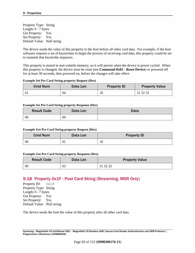
9 - Properties
Dynamag / MagneSafe V5 IntelliHead USB / MagneSafe V5 Readers USB| Secure Card Reader Authenticators and OEM Products |
Programmer’s Reference (COMMANDS)
Page 83 of 152 (D998200176-11)
Property Type: String
Length: 0 - 7 bytes
Get Property: Yes
Set Property: Yes
Default Value: Null string
The device sends the value of this property to the host before all other card data. For example, if the host
software requires a set of keystrokes to begin the process of receiving card data, this property could be set
to transmit that keystroke sequence.
This property is stored in non-volatile memory, so it will persist when the device is power cycled. When
this property is changed, the device must be reset (see Command 0x02 - Reset Device) or powered off
for at least 30 seconds, then powered on, before the changes will take effect.
Example Set Pre Card String property Request (Hex)
Cmd Num Data Len Property ID Property Value
01 04 1E 31 32 33
Example Set Pre Card String property Response (Hex)
Result Code Data Len Data
00 00
Example Get Pre Card String property Request (Hex)
Cmd Num Data Len Property ID
00 01 1E
Example Get Pre Card String property Response (Hex)
Result Code Data Len Property Value
00 03 31 32 33
9.18 Property 0x1F - Post Card String (Streaming, MSR Only) Property ID: 0x1F
Property Type: String
Length: 0 - 7 bytes
Get Property: Yes
Set Property: Yes
Default Value: Null string.
The device sends the host the value of this property after all other card data.
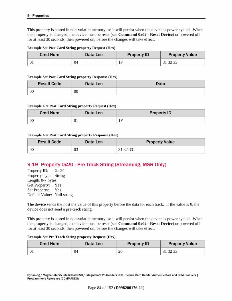
9 - Properties
Dynamag / MagneSafe V5 IntelliHead USB / MagneSafe V5 Readers USB| Secure Card Reader Authenticators and OEM Products |
Programmer’s Reference (COMMANDS)
Page 84 of 152 (D998200176-11)
This property is stored in non-volatile memory, so it will persist when the device is power cycled. When
this property is changed, the device must be reset (see Command 0x02 - Reset Device) or powered off
for at least 30 seconds, then powered on, before the changes will take effect.
Example Set Post Card String property Request (Hex)
Cmd Num Data Len Property ID Property Value
01 04 1F 31 32 33
Example Set Post Card String property Response (Hex)
Result Code Data Len Data
00 00
Example Get Post Card String property Request (Hex)
Cmd Num Data Len Property ID
00 01 1F
Example Get Post Card String property Response (Hex)
Result Code Data Len Property Value
00 03 31 32 33
9.19 Property 0x20 - Pre Track String (Streaming, MSR Only) Property ID: 0x20
Property Type: String
Length: 0-7 bytes
Get Property: Yes
Set Property: Yes
Default Value: Null string
The device sends the host the value of this property before the data for each track. If the value is 0, the
device does not send a pre-track string.
This property is stored in non-volatile memory, so it will persist when the device is power cycled. When
this property is changed, the device must be reset (see Command 0x02 - Reset Device) or powered off
for at least 30 seconds, then powered on, before the changes will take effect.
Example Set Pre Track String property Request (Hex)
Cmd Num Data Len Property ID Property Value
01 04 20 31 32 33

9 - Properties
Dynamag / MagneSafe V5 IntelliHead USB / MagneSafe V5 Readers USB| Secure Card Reader Authenticators and OEM Products |
Programmer’s Reference (COMMANDS)
Page 85 of 152 (D998200176-11)
Example Set Pre Track String property Response (Hex)
Result Code Data Len Data
00 00
Example Get Pre Track String property Request (Hex)
Cmd Num Data Len Property ID
00 01 20
Example Get Pre Track String property Response (Hex)
Result Code Data Len Property Value
00 03 31 32 33
9.20 Property 0x21 - Post Track String (Streaming, MSR Only) Property ID: 0x21
Property Type: String
Length: 0-7 bytes
Get Property: Yes
Set Property: Yes
Default Value: Null string.
The device sends the host the value of this property after the data for each track. If the value is 0, the
device does not send a pre-track string.
This property is stored in non-volatile memory, so it will persist when the device is power cycled. When
this property is changed, the device must be reset (see Command 0x02 - Reset Device) or powered off
for at least 30 seconds, then powered on, before the changes will take effect.
Example Set Post Track String property Request (Hex)
Cmd Num Data Len Property ID Property Value
01 04 21 31 32 33
Example Set Post Track String property Response (Hex)
Result Code Data Len Data
00 00
Example Get Post Track String property Request (Hex)
Cmd Num Data Len Property ID
00 01 21

9 - Properties
Dynamag / MagneSafe V5 IntelliHead USB / MagneSafe V5 Readers USB| Secure Card Reader Authenticators and OEM Products |
Programmer’s Reference (COMMANDS)
Page 86 of 152 (D998200176-11)
Example Get Post Track String property Response (Hex)
Result Code Data Len Property Value
00 03 31 32 33
9.21 Property 0x22 - Termination String (Streaming, MSR Only) Property ID: 0x22
Property Type: String
Length: 0-7 bytes
Get Property: Yes
Set Property: Yes
Default Value: 0x0D (carriage return)
The device sends the host the value of this property after the all the data for a transaction. If the value is
0, the device does not send a termination string.
This property is stored in non-volatile memory, so it will persist when the device is power cycled. When
this property is changed, the device must be reset (see Command 0x02 - Reset Device) or powered off
for at least 30 seconds, then powered on, before the changes will take effect.
Example Set property Request (Hex)
Cmd Num Data Len Property ID Property Value
01 02 22 0D
Example Set property Response (Hex)
Result Code Data Len Data
00 00
Example Get property Request (Hex)
Cmd Num Data Len Property ID
00 01 22
Example Get property Response (Hex)
Result Code Data Len Property Value
00 01 0D
9.22 Property 0x23 - Field Separator (Streaming, MSR Only) Property ID: 0x23
Property Type: Byte
Length: 1 byte
Get Property: Yes

9 - Properties
Dynamag / MagneSafe V5 IntelliHead USB / MagneSafe V5 Readers USB| Secure Card Reader Authenticators and OEM Products |
Programmer’s Reference (COMMANDS)
Page 87 of 152 (D998200176-11)
Set Property: Yes
Default Value: 0x7C (‘|’)
This property stores the character the device will use for P35 (see section 4.2 How to Use Streaming
Format). If the value is in the range 1 - 127, the device sends the equivalent ASCII character. If the
value is 0, the device does not send a delimiter, which is inadvisable.
This property is stored in non-volatile memory, so it will persist when the device is power cycled. When
this property is changed, the device must be reset (see Command 0x02 - Reset Device) or powered off
for at least 30 seconds, then powered on, before the changes will take effect.
Example Set property Request (Hex)
Cmd Num Data Len Property ID Property Value
01 02 23 7C
Example Set property Response (Hex)
Result Code Data Len Data
00 00
Example Get property Request (Hex)
Cmd Num Data Len Property ID
00 01 23
Example Get property Response (Hex)
Result Code Data Len Property Value
00 01 7C
9.23 Property 0x24 - Start Sentinel Track 1 ISO ABA (Streaming Only, MSR
Only or Keypad Entry Only) Property ID: 0x24
Property Type: Byte
Length: 1 byte
Get Property: Yes
Set Property: Yes
Default Value: 0x25 (‘%’)
This property stores the character the device will use to replace the Track 1 Start Sentinel for cards where
it recognizes Track 1 encoded in ISO/ABA format. The default value is the standard ISO/ABA Track 1
Start Sentinel, meaning no replacement. If the value is in the range 1 - 127, the device sends the
equivalent ASCII character. If the value is 0, the device will not send a character.

9 - Properties
Dynamag / MagneSafe V5 IntelliHead USB / MagneSafe V5 Readers USB| Secure Card Reader Authenticators and OEM Products |
Programmer’s Reference (COMMANDS)
Page 88 of 152 (D998200176-11)
This property is stored in non-volatile memory, so it will persist when the device is power cycled. When
this property is changed, the device must be reset (see Command 0x02 - Reset Device) or powered off
for at least 30 seconds, then powered on, before the changes will take effect.
9.24 Property 0x25 - Start Sentinel Track 2 ISO ABA (Streaming, MSR Only) Property ID: 0x25
Property Type: Byte
Length: 1 byte
Get Property: Yes
Set Property: Yes
Default Value: 0x3B (‘;’)
This property stores the character the device will use to replace the Track 2 Start Sentinel for cards where
it recognizes Track 2 encoded in ISO/ABA format. The default value is the standard ISO/ABA Track 2
Start Sentinel, meaning no replacement. If the value is in the range 1 - 127, the device sends the
equivalent ASCII character. If the value is 0, the device will not send a character.
This property is stored in non-volatile memory, so it will persist when the device is power cycled. When
this property is changed, the device must be reset (see Command 0x02 - Reset Device) or powered off
for at least 30 seconds, then powered on, before the changes will take effect.
9.25 Property 0x26 - Start Sentinel Track 3 ISO ABA (Streaming, MSR Only) Property ID: 0x26
Property Type: Byte
Length: 1 byte
Get Property: Yes
Set Property: Yes
Default Value: 0x2B (‘+’)
This property stores the character the device will use as a Track 3 Start Sentinel for cards where it
recognizes Track 3 encoded in ISO/ABA format. If the value is in the range 1 - 127, the device sends the
equivalent ASCII character. If the value is 0, the device will not send a character.
This property is stored in non-volatile memory, so it will persist when the device is power cycled. When
this property is changed, the device must be reset (see Command 0x02 - Reset Device) or powered off
for at least 30 seconds, then powered on, before the changes will take effect.
9.26 Property 0x27 - Start Sentinel Track 3 AAMVA (Streaming, MSR Only) Property ID: 0x27
Property Type: Byte
Length: 1 byte
Get Property: Yes
Set Property: Yes
Default Value: 0x23 (‘#’)
This property stores the character the device will use as a Track 3 Start Sentinel for cards where it
recognizes Track 3 encoded in AAMVA format. If the value is in the range 1 - 127, the device sends the
equivalent ASCII character. If the value is 0, the device will not send a character.

9 - Properties
Dynamag / MagneSafe V5 IntelliHead USB / MagneSafe V5 Readers USB| Secure Card Reader Authenticators and OEM Products |
Programmer’s Reference (COMMANDS)
Page 89 of 152 (D998200176-11)
This property is stored in non-volatile memory, so it will persist when the device is power cycled. When
this property is changed, the device must be reset (see Command 0x02 - Reset Device) or powered off
for at least 30 seconds, then powered on, before the changes will take effect.
9.27 Property 0x28 - Start Sentinel Track 2 7bits (Streaming, MSR Only) Property ID: 0x28
Property Type: Byte
Length: 1 byte
Get Property: Yes
Set Property: Yes
Default Value: 0x40 (‘@’)
This property stores the character the device will use to replace the Track 2 Start Sentinel for cards where
it recognizes Track 2 encoded in the 7-bit ISO format used for Track 1. If the value is in the range 1 -
127, the device sends the equivalent ASCII character. If the value is 0, the device will not send a
character.
This property is stored in non-volatile memory, so it will persist when the device is power cycled. When
this property is changed, the device must be reset (see Command 0x02 - Reset Device) or powered off
for at least 30 seconds, then powered on, before the changes will take effect.
9.28 Property 0x29 - Start Sentinel Track 3 7bits (Streaming, MSR Only, 3-
Track Only) Property ID: 0x29
Property Type: Byte
Length: 1 byte
Get Property: Yes
Set Property: Yes
Default Value: 0x26 (‘&’)
This property stores the character the device will use to replace the Track 3 Start Sentinel for cards where
it recognizes Track 3 encoded in the 7-bit ISO format used for Track 1. If the value is in the range 1 -
127, the device sends the equivalent ASCII character. If the value is 0, the device will not send a
character.
This property is stored in non-volatile memory, so it will persist when the device is power cycled. When
this property is changed, the device must be reset (see Command 0x02 - Reset Device) or powered off
for at least 30 seconds, then powered on, before the changes will take effect.
9.29 Property 0x2B - End Sentinel (Streaming, MSR Only) Property ID: 0x2B
Property Type: Byte
Length: 1 byte
Get Property: Yes
Set Property: Yes
Default Value: 0x3F (‘?’)
This property stores the character the device will send as the End Sentinel for all tracks in any card data
format [unless it is overridden, track by track, by Property 0x2D - End Sentinel Track 1 (Streaming,
MSR Only), Property 0x2E - End Sentinel Track 2 (Streaming, MSR Only), or Property 0x2F - End

9 - Properties
Dynamag / MagneSafe V5 IntelliHead USB / MagneSafe V5 Readers USB| Secure Card Reader Authenticators and OEM Products |
Programmer’s Reference (COMMANDS)
Page 90 of 152 (D998200176-11)
Sentinel Track 3 (Streaming, MSR Only, 3-Track Only)]. In tracks that have a standard end sentinel
embedded, it will replace them. If the value is in the range 1 - 127, the device sends the equivalent ASCII
character. If the value is 0, the device will not send a character.
This property is stored in non-volatile memory, so it will persist when the device is power cycled. When
this property is changed, the device must be reset (see Command 0x02 - Reset Device) or powered off
for at least 30 seconds, then powered on, before the changes will take effect.
9.30 Property 0x2C - Format Code (Streaming, MSR Only) Property ID: 0x2C
Property Type: String
Length: 4 bytes
Get Property: Yes
Set Property: Yes
Default Value: “0000”
This property specifies the Format Code the device will include when it sends card swipe data to the host
[see section 7.23 Format Code (Streaming)], and is designed to allow programmers of host software to
populate the final three characters as “notes” the host software can use to determine how to parse or
interpret the accompanying data. When setting this property, the host must send four characters: The
device will ignore the first character, which is reserved for MagTek/device use, and will change the final
three characters of the property to the final three characters the host specified.
The value can be interpreted as follows:
By default, the Format Code is “0000”.
If the manufacturer configures Property 0x30 - Send Remaining MSR Transactions Counter
(Streaming, MSR Only) to send the MSR Transactions Remaining counter (successful completion
of the Set Encryption Counter command documented in D99300006 MagneSafe V5 Key Loading
Manual) the device changes the Format Code from “0000” to “0001.”
If the host directly sets the value of the Format Code property, the new value overrides the factory set
value. The host can change the final three characters, but making such a change will automatically
cause the first character to change to “1”.
If a user or host software changes a setting that automatically updates Format Code, the first character
of the Format Code will change to a “1”. Such settings include:
o Property 0x15 - MagnePrint Flags (HID, Streaming, MSR Only)
o Property 0x16 - Active Keymap (KB, MSR Only)
o Property 0x17 - ASCII to Keypress Conversion Type (KB, MSR Only)
o Property 0x14 - Track Data Send Flags (KB/Streaming, MSR Only)
o Property 0x19 - CRC Flags (Streaming, MSR Only)
o Property 0x1E - Pre Card String (Streaming, MSR Only)
o Property 0x1F - Post Card String (Streaming, MSR Only)
o Property 0x20 - Pre Track String (Streaming, MSR Only)
o Property 0x21 - Post Track String (Streaming, MSR Only)
o Property 0x22 - Termination String (Streaming, MSR Only)
o Property 0x23 - Field Separator (Streaming, MSR Only)
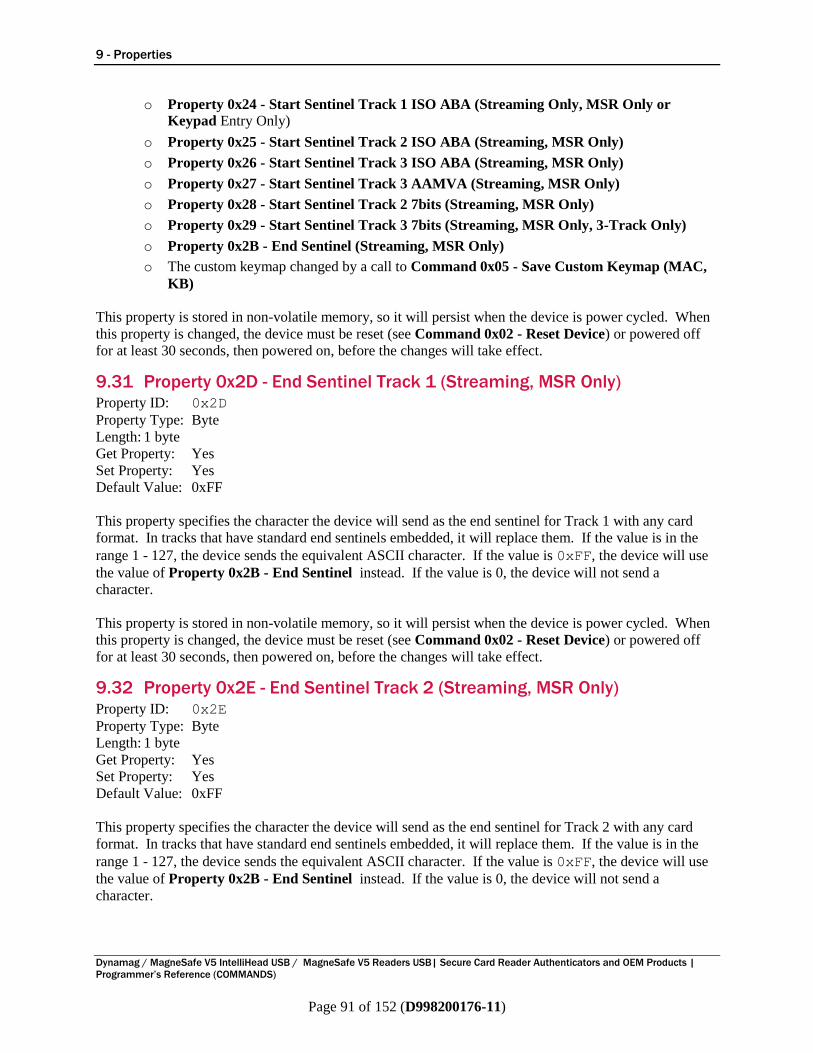
9 - Properties
Dynamag / MagneSafe V5 IntelliHead USB / MagneSafe V5 Readers USB| Secure Card Reader Authenticators and OEM Products |
Programmer’s Reference (COMMANDS)
Page 91 of 152 (D998200176-11)
o Property 0x24 - Start Sentinel Track 1 ISO ABA (Streaming Only, MSR Only or
Keypad Entry Only)
o Property 0x25 - Start Sentinel Track 2 ISO ABA (Streaming, MSR Only)
o Property 0x26 - Start Sentinel Track 3 ISO ABA (Streaming, MSR Only)
o Property 0x27 - Start Sentinel Track 3 AAMVA (Streaming, MSR Only)
o Property 0x28 - Start Sentinel Track 2 7bits (Streaming, MSR Only)
o Property 0x29 - Start Sentinel Track 3 7bits (Streaming, MSR Only, 3-Track Only)
o Property 0x2B - End Sentinel (Streaming, MSR Only)
o The custom keymap changed by a call to Command 0x05 - Save Custom Keymap (MAC,
KB)
This property is stored in non-volatile memory, so it will persist when the device is power cycled. When
this property is changed, the device must be reset (see Command 0x02 - Reset Device) or powered off
for at least 30 seconds, then powered on, before the changes will take effect.
9.31 Property 0x2D - End Sentinel Track 1 (Streaming, MSR Only) Property ID: 0x2D
Property Type: Byte
Length: 1 byte
Get Property: Yes
Set Property: Yes
Default Value: 0xFF
This property specifies the character the device will send as the end sentinel for Track 1 with any card
format. In tracks that have standard end sentinels embedded, it will replace them. If the value is in the
range 1 - 127, the device sends the equivalent ASCII character. If the value is 0xFF, the device will use
the value of Property 0x2B - End Sentinel instead. If the value is 0, the device will not send a
character.
This property is stored in non-volatile memory, so it will persist when the device is power cycled. When
this property is changed, the device must be reset (see Command 0x02 - Reset Device) or powered off
for at least 30 seconds, then powered on, before the changes will take effect.
9.32 Property 0x2E - End Sentinel Track 2 (Streaming, MSR Only) Property ID: 0x2E
Property Type: Byte
Length: 1 byte
Get Property: Yes
Set Property: Yes
Default Value: 0xFF
This property specifies the character the device will send as the end sentinel for Track 2 with any card
format. In tracks that have standard end sentinels embedded, it will replace them. If the value is in the
range 1 - 127, the device sends the equivalent ASCII character. If the value is 0xFF, the device will use
the value of Property 0x2B - End Sentinel instead. If the value is 0, the device will not send a
character.
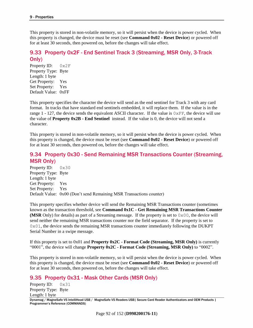
9 - Properties
Dynamag / MagneSafe V5 IntelliHead USB / MagneSafe V5 Readers USB| Secure Card Reader Authenticators and OEM Products |
Programmer’s Reference (COMMANDS)
Page 92 of 152 (D998200176-11)
This property is stored in non-volatile memory, so it will persist when the device is power cycled. When
this property is changed, the device must be reset (see Command 0x02 - Reset Device) or powered off
for at least 30 seconds, then powered on, before the changes will take effect.
9.33 Property 0x2F - End Sentinel Track 3 (Streaming, MSR Only, 3-Track
Only) Property ID: 0x2F
Property Type: Byte
Length: 1 byte
Get Property: Yes
Set Property: Yes
Default Value: 0xFF
This property specifies the character the device will send as the end sentinel for Track 3 with any card
format. In tracks that have standard end sentinels embedded, it will replace them. If the value is in the
range 1 - 127, the device sends the equivalent ASCII character. If the value is 0xFF, the device will use
the value of Property 0x2B - End Sentinel instead. If the value is 0, the device will not send a
character.
This property is stored in non-volatile memory, so it will persist when the device is power cycled. When
this property is changed, the device must be reset (see Command 0x02 - Reset Device) or powered off
for at least 30 seconds, then powered on, before the changes will take effect.
9.34 Property 0x30 - Send Remaining MSR Transactions Counter (Streaming,
MSR Only) Property ID: 0x30
Property Type: Byte
Length: 1 byte
Get Property: Yes
Set Property: Yes
Default Value: 0x00 (Don’t send Remaining MSR Transactions counter)
This property specifies whether device will send the Remaining MSR Transactions counter (sometimes
known as the transaction threshold, see Command 0x1C - Get Remaining MSR Transactions Counter
(MSR Only) for details) as part of a Streaming message. If the property is set to 0x00, the device will
send neither the remaining MSR transactions counter nor the field separator. If the property is set to
0x01, the device sends the remaining MSR transactions counter immediately following the DUKPT
Serial Number in a swipe message.
If this property is set to 0x01 and Property 0x2C - Format Code (Streaming, MSR Only) is currently
“0001”, the device will change Property 0x2C - Format Code (Streaming, MSR Only) to “0002”.
This property is stored in non-volatile memory, so it will persist when the device is power cycled. When
this property is changed, the device must be reset (see Command 0x02 - Reset Device) or powered off
for at least 30 seconds, then powered on, before the changes will take effect.
9.35 Property 0x31 - Mask Other Cards (MSR Only) Property ID: 0x31
Property Type: Byte
Length: 1 byte

9 - Properties
Dynamag / MagneSafe V5 IntelliHead USB / MagneSafe V5 Readers USB| Secure Card Reader Authenticators and OEM Products |
Programmer’s Reference (COMMANDS)
Page 93 of 152 (D998200176-11)
Get Property: Yes
Set Property: Yes
Default Value: 0x00 (Don’t Mask Other cards)
This property designates whether cards which do not decode as either ISO/ABA (Financial) or AAMVA
(Driver License) format should be sent with their data masked or in the clear. The default value (0x00)
is to send the data in the clear. If this property is set to 0x01, the device will send the track(s) to the host
using a “0” for each byte of track data the device reads from the card.
If a card is encoded according to ISO/ABA rules (Track 1 in 7 bit format, Tracks 2 and Track 3 in 5 bit
format), and Track 1 does not begin with the character ‘B’, the device will always send the Track 1
Masked Data value unmasked, regardless of the value of this property. See Appendix E for details.
This property is stored in non-volatile memory, so it will persist when the device is power cycled. When
this property is changed, the device must be reset (see Command 0x02 - Reset Device) or powered off
for at least 30 seconds, then powered on, before the changes will take effect.
9.36 Property 0x34 - Send Clear AAMVA Card Data (MSR Only) Property ID: 0x34
Property Type: Byte
Length: 1 byte
Get Property: Yes
Set Property: Yes
Default Value: 0x00
This property controls how the device sends AAMVA card data when the security level is higher than
Security Level 2:
0 = Send masked AAMVA card data.
1 = Send clear AAMVA card data.
This property is stored in non-volatile memory, so it will persist when the device is power cycled. When
this property is changed, the device must be reset (see Command 0x02 - Reset Device) or powered off
for at least 30 seconds, then powered on, before the changes will take effect.
Example Set Send Clear AAMVA Card Data property Request (Hex)
Cmd Num Data Len Property ID Data
01 06 34 01 xx xx xx xx
xx xx xx xx is the MAC.
Example Set Send Clear AAMVA Card Data property Response (Hex)
Result Code Data Len Data
00 00
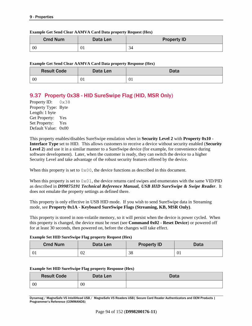
9 - Properties
Dynamag / MagneSafe V5 IntelliHead USB / MagneSafe V5 Readers USB| Secure Card Reader Authenticators and OEM Products |
Programmer’s Reference (COMMANDS)
Page 94 of 152 (D998200176-11)
Example Get Send Clear AAMVA Card Data property Request (Hex)
Cmd Num Data Len Property ID
00 01 34
Example Get Send Clear AAMVA Card Data property Response (Hex)
Result Code Data Len Data
00 01 01
9.37 Property 0x38 - HID SureSwipe Flag (HID, MSR Only) Property ID: 0x38
Property Type: Byte
Length: 1 byte
Get Property: Yes
Set Property: Yes
Default Value: 0x00
This property enables/disables SureSwipe emulation when in Security Level 2 with Property 0x10 -
Interface Type set to HID. This allows customers to receive a device without security enabled (Security
Level 2) and use it in a similar manner to a SureSwipe device (for example, for convenience during
software development). Later, when the customer is ready, they can switch the device to a higher
Security Level and take advantage of the robust security features offered by the device.
When this property is set to 0x00, the device functions as described in this document.
When this property is set to 0x01, the device returns card swipes and enumerates with the same VID/PID
as described in D99875191 Technical Reference Manual, USB HID SureSwipe & Swipe Reader. It
does not emulate the property settings as defined there.
This property is only effective in USB HID mode. If you wish to send SureSwipe data in Streaming
mode, see Property 0x1A - Keyboard SureSwipe Flags (Streaming, KB, MSR Only).
This property is stored in non-volatile memory, so it will persist when the device is power cycled. When
this property is changed, the device must be reset (see Command 0x02 - Reset Device) or powered off
for at least 30 seconds, then powered on, before the changes will take effect.
Example Set HID SureSwipe Flag property Request (Hex)
Cmd Num Data Len Property ID Data
01 02 38 01
Example Set HID SureSwipe Flag property Response (Hex)
Result Code Data Len Data
00 00
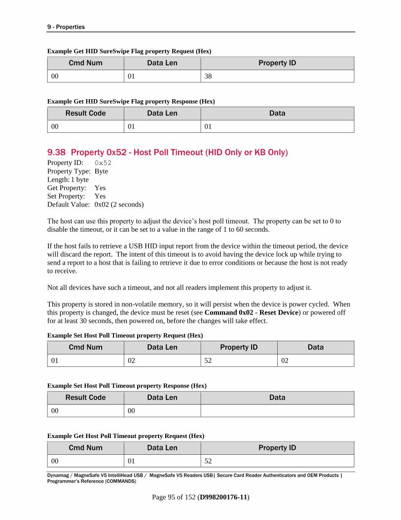
9 - Properties
Dynamag / MagneSafe V5 IntelliHead USB / MagneSafe V5 Readers USB| Secure Card Reader Authenticators and OEM Products |
Programmer’s Reference (COMMANDS)
Page 95 of 152 (D998200176-11)
Example Get HID SureSwipe Flag property Request (Hex)
Cmd Num Data Len Property ID
00 01 38
Example Get HID SureSwipe Flag property Response (Hex)
Result Code Data Len Data
00 01 01
9.38 Property 0x52 - Host Poll Timeout (HID Only or KB Only) Property ID: 0x52
Property Type: Byte
Length: 1 byte
Get Property: Yes
Set Property: Yes
Default Value: 0x02 (2 seconds)
The host can use this property to adjust the device’s host poll timeout. The property can be set to 0 to
disable the timeout, or it can be set to a value in the range of 1 to 60 seconds.
If the host fails to retrieve a USB HID input report from the device within the timeout period, the device
will discard the report. The intent of this timeout is to avoid having the device lock up while trying to
send a report to a host that is failing to retrieve it due to error conditions or because the host is not ready
to receive.
Not all devices have such a timeout, and not all readers implement this property to adjust it.
This property is stored in non-volatile memory, so it will persist when the device is power cycled. When
this property is changed, the device must be reset (see Command 0x02 - Reset Device) or powered off
for at least 30 seconds, then powered on, before the changes will take effect.
Example Set Host Poll Timeout property Request (Hex)
Cmd Num Data Len Property ID Data
01 02 52 02
Example Set Host Poll Timeout property Response (Hex)
Result Code Data Len Data
00 00
Example Get Host Poll Timeout property Request (Hex)
Cmd Num Data Len Property ID
00 01 52
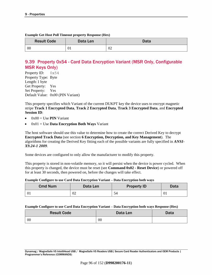
9 - Properties
Dynamag / MagneSafe V5 IntelliHead USB / MagneSafe V5 Readers USB| Secure Card Reader Authenticators and OEM Products |
Programmer’s Reference (COMMANDS)
Page 96 of 152 (D998200176-11)
Example Get Host Poll Timeout property Response (Hex)
Result Code Data Len Data
00 01 02
9.39 Property 0x54 - Card Data Encryption Variant (MSR Only, Configurable
MSR Keys Only) Property ID: 0x54
Property Type: Byte
Length: 1 byte
Get Property: Yes
Set Property: Yes
Default Value: 0x00 (PIN Variant)
This property specifies which Variant of the current DUKPT key the device uses to encrypt magnetic
stripe Track 1 Encrypted Data, Track 2 Encrypted Data, Track 3 Encrypted Data, and Encrypted
Session ID:
0x00 = Use PIN Variant
0x01 = Use Data Encryption Both Ways Variant
The host software should use this value to determine how to create the correct Derived Key to decrypt
Encrypted Track Data (see section 6 Encryption, Decryption, and Key Management). The
algorithms for creating the Derived Key fitting each of the possible variants are fully specified in ANSI-
X9.24-1 2009.
Some devices are configured to only allow the manufacturer to modify this property.
This property is stored in non-volatile memory, so it will persist when the device is power cycled. When
this property is changed, the device must be reset (see Command 0x02 - Reset Device) or powered off
for at least 30 seconds, then powered on, before the changes will take effect.
Example Configure to use Card Data Encryption Variant – Data Encryption both ways
Cmd Num Data Len Property ID Data
01 02 54 01
Example Configure to use Card Data Encryption Variant – Data Encryption both ways Response (Hex)
Result Code Data Len Data
00 00

9 - Properties
Dynamag / MagneSafe V5 IntelliHead USB / MagneSafe V5 Readers USB| Secure Card Reader Authenticators and OEM Products |
Programmer’s Reference (COMMANDS)
Page 97 of 152 (D998200176-11)
Example Get Card Data Encryption Variant property
Cmd Num Data Len Property ID
00 01 54
Example Get Card Data Encryption Variant Response (Hex)
Result Code Data Len Data
00 01 01
9.40 Property 0x57 - SHA Hash Configuration (HID, TLV, SHA-1, SHA-256,
MSR Only) Property ID: 0x57
Property Type: Byte
Length: 1 byte
Get Property: Yes
Set Property: Yes
Default Value: 0x00
This property specifies whether and how the device returns a SHA-x Hash code with swipe data. See
section 7.18 SHA-1 Hashed Track 2 Data (HID, TLV, GATT, SHA-1).
The possible options are:
Value Meaning
0x00 Device will send a SHA-1 Hash code of all Track 2 data
0x01 Device will send a SHA-1 Hash code of the Track 2 PAN
0x02 Device will send a Salted SHA-1 Hash code of all Track 2 data
0x03 Device will send a Salted SHA-1 Hash code of the Track 2 PAN
0x04 Device will send a SHA-256 Hash code of all Track 2 data
0x05 Device will send a SHA-256 Hash code of the Track 2 PAN
0x06 Device will send a Salted SHA-256 Hash code of all Track 2 data
0x07 Device will send a Salted SHA-256 Hash code of the Track 2 PAN
0xFF Device will not send any Hash code
Some devices are configured to only allow the manufacturer to modify this property.
This property is stored in non-volatile memory, so it will persist when the device is power cycled. When
this property is changed, the device must be reset (see Command 0x02 - Reset Device) or powered off
for at least 30 seconds, then powered on, before the changes will take effect.
Example Set SHA Hash Configuration property Request (Hex)
Cmd Num Data Len Property ID Data
01 02 57 07
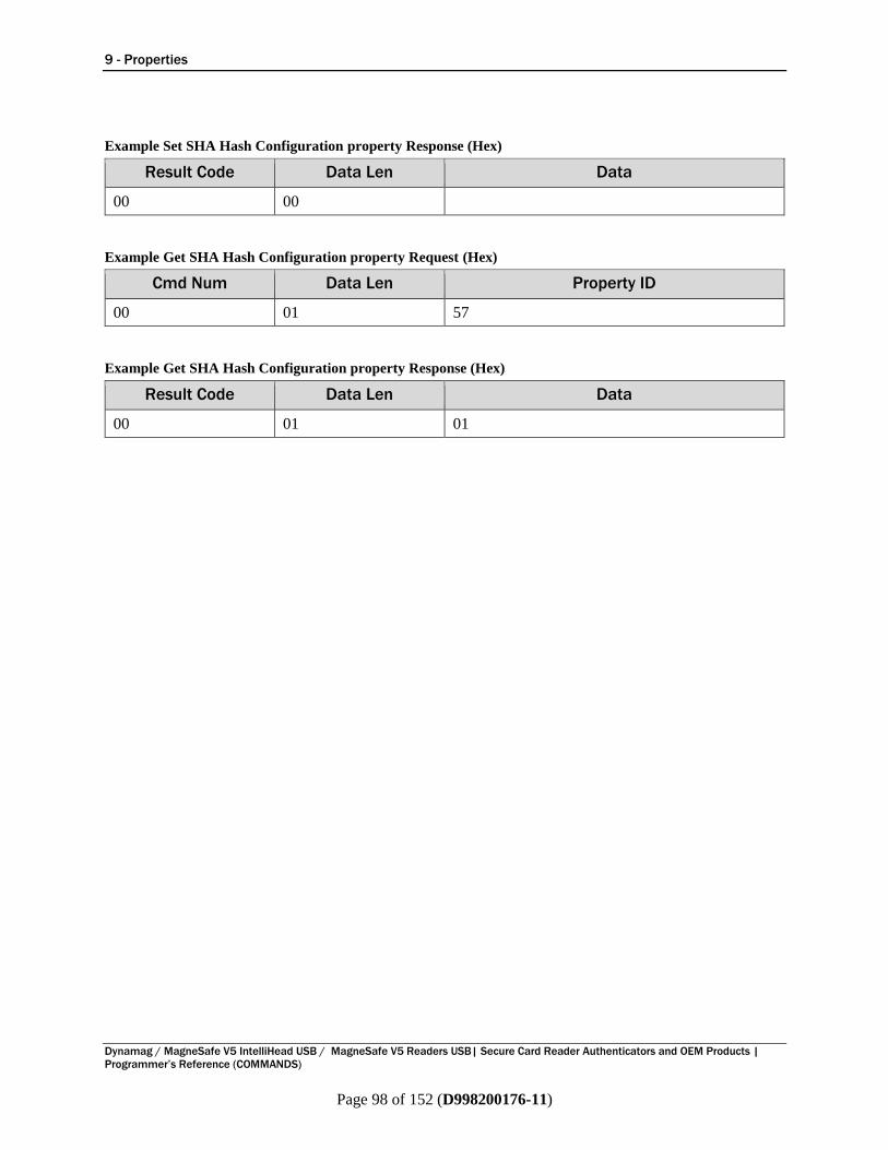
9 - Properties
Dynamag / MagneSafe V5 IntelliHead USB / MagneSafe V5 Readers USB| Secure Card Reader Authenticators and OEM Products |
Programmer’s Reference (COMMANDS)
Page 98 of 152 (D998200176-11)
Example Set SHA Hash Configuration property Response (Hex)
Result Code Data Len Data
00 00
Example Get SHA Hash Configuration property Request (Hex)
Cmd Num Data Len Property ID
00 01 57
Example Get SHA Hash Configuration property Response (Hex)
Result Code Data Len Data
00 01 01
Appendix A - Examples
Dynamag / MagneSafe V5 IntelliHead USB / MagneSafe V5 Readers USB| Secure Card Reader Authenticators and OEM Products |
Programmer’s Reference (COMMANDS)
Page 99 of 152 (D998200176-11)
Appendix A Examples This section includes direct command examples and information about using demonstration software. In
addition to the examples here, source code with detailed comments is included with the demo software
and can be used as a guide for custom software development.
The book USB Complete by Jan Axelson is also a good guide for software developers, especially the
chapter “Human Interface Devices: Host Applications.”
A.1 Command Examples This section provides examples of command sequences and cryptographic operations. Each example
shows a sequence as it actually runs, so developers of custom software can check their code against the
examples step-by-step to make sure the software is parsing and computing values correctly.
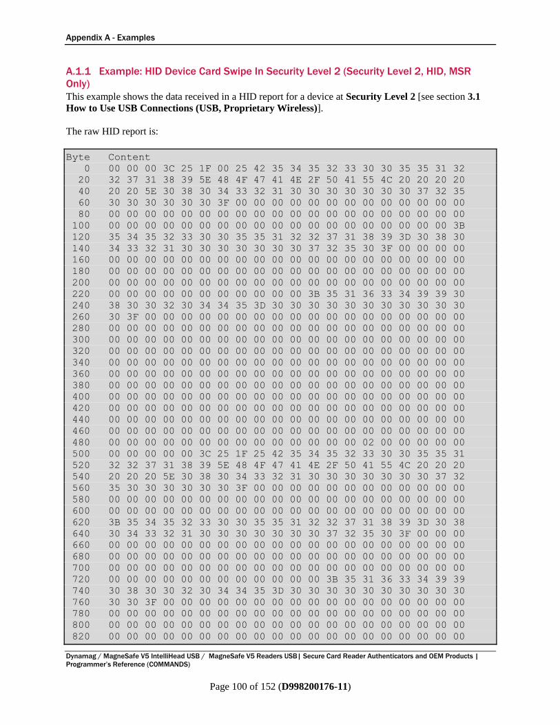
Appendix A - Examples
Dynamag / MagneSafe V5 IntelliHead USB / MagneSafe V5 Readers USB| Secure Card Reader Authenticators and OEM Products |
Programmer’s Reference (COMMANDS)
Page 100 of 152 (D998200176-11)
A.1.1 Example: HID Device Card Swipe In Security Level 2 (Security Level 2, HID, MSR
Only)
This example shows the data received in a HID report for a device at Security Level 2 [see section 3.1
How to Use USB Connections (USB, Proprietary Wireless)].
The raw HID report is:
Byte Content
0 00 00 00 3C 25 1F 00 25 42 35 34 35 32 33 30 30 35 35 31 32
20 32 37 31 38 39 5E 48 4F 47 41 4E 2F 50 41 55 4C 20 20 20 20
40 20 20 5E 30 38 30 34 33 32 31 30 30 30 30 30 30 30 37 32 35
60 30 30 30 30 30 30 3F 00 00 00 00 00 00 00 00 00 00 00 00 00
80 00 00 00 00 00 00 00 00 00 00 00 00 00 00 00 00 00 00 00 00
100 00 00 00 00 00 00 00 00 00 00 00 00 00 00 00 00 00 00 00 3B
120 35 34 35 32 33 30 30 35 35 31 32 32 37 31 38 39 3D 30 38 30
140 34 33 32 31 30 30 30 30 30 30 30 37 32 35 30 3F 00 00 00 00
160 00 00 00 00 00 00 00 00 00 00 00 00 00 00 00 00 00 00 00 00
180 00 00 00 00 00 00 00 00 00 00 00 00 00 00 00 00 00 00 00 00
200 00 00 00 00 00 00 00 00 00 00 00 00 00 00 00 00 00 00 00 00
220 00 00 00 00 00 00 00 00 00 00 00 3B 35 31 36 33 34 39 39 30
240 38 30 30 32 30 34 34 35 3D 30 30 30 30 30 30 30 30 30 30 30
260 30 3F 00 00 00 00 00 00 00 00 00 00 00 00 00 00 00 00 00 00
280 00 00 00 00 00 00 00 00 00 00 00 00 00 00 00 00 00 00 00 00
300 00 00 00 00 00 00 00 00 00 00 00 00 00 00 00 00 00 00 00 00
320 00 00 00 00 00 00 00 00 00 00 00 00 00 00 00 00 00 00 00 00
340 00 00 00 00 00 00 00 00 00 00 00 00 00 00 00 00 00 00 00 00
360 00 00 00 00 00 00 00 00 00 00 00 00 00 00 00 00 00 00 00 00
380 00 00 00 00 00 00 00 00 00 00 00 00 00 00 00 00 00 00 00 00
400 00 00 00 00 00 00 00 00 00 00 00 00 00 00 00 00 00 00 00 00
420 00 00 00 00 00 00 00 00 00 00 00 00 00 00 00 00 00 00 00 00
440 00 00 00 00 00 00 00 00 00 00 00 00 00 00 00 00 00 00 00 00
460 00 00 00 00 00 00 00 00 00 00 00 00 00 00 00 00 00 00 00 00
480 00 00 00 00 00 00 00 00 00 00 00 00 00 00 02 00 00 00 00 00
500 00 00 00 00 00 3C 25 1F 25 42 35 34 35 32 33 30 30 35 35 31
520 32 32 37 31 38 39 5E 48 4F 47 41 4E 2F 50 41 55 4C 20 20 20
540 20 20 20 5E 30 38 30 34 33 32 31 30 30 30 30 30 30 30 37 32
560 35 30 30 30 30 30 30 3F 00 00 00 00 00 00 00 00 00 00 00 00
580 00 00 00 00 00 00 00 00 00 00 00 00 00 00 00 00 00 00 00 00
600 00 00 00 00 00 00 00 00 00 00 00 00 00 00 00 00 00 00 00 00
620 3B 35 34 35 32 33 30 30 35 35 31 32 32 37 31 38 39 3D 30 38
640 30 34 33 32 31 30 30 30 30 30 30 30 37 32 35 30 3F 00 00 00
660 00 00 00 00 00 00 00 00 00 00 00 00 00 00 00 00 00 00 00 00
680 00 00 00 00 00 00 00 00 00 00 00 00 00 00 00 00 00 00 00 00
700 00 00 00 00 00 00 00 00 00 00 00 00 00 00 00 00 00 00 00 00
720 00 00 00 00 00 00 00 00 00 00 00 00 3B 35 31 36 33 34 39 39
740 30 38 30 30 32 30 34 34 35 3D 30 30 30 30 30 30 30 30 30 30
760 30 30 3F 00 00 00 00 00 00 00 00 00 00 00 00 00 00 00 00 00
780 00 00 00 00 00 00 00 00 00 00 00 00 00 00 00 00 00 00 00 00
800 00 00 00 00 00 00 00 00 00 00 00 00 00 00 00 00 00 00 00 00
820 00 00 00 00 00 00 00 00 00 00 00 00 00 00 00 00 00 00 00 00
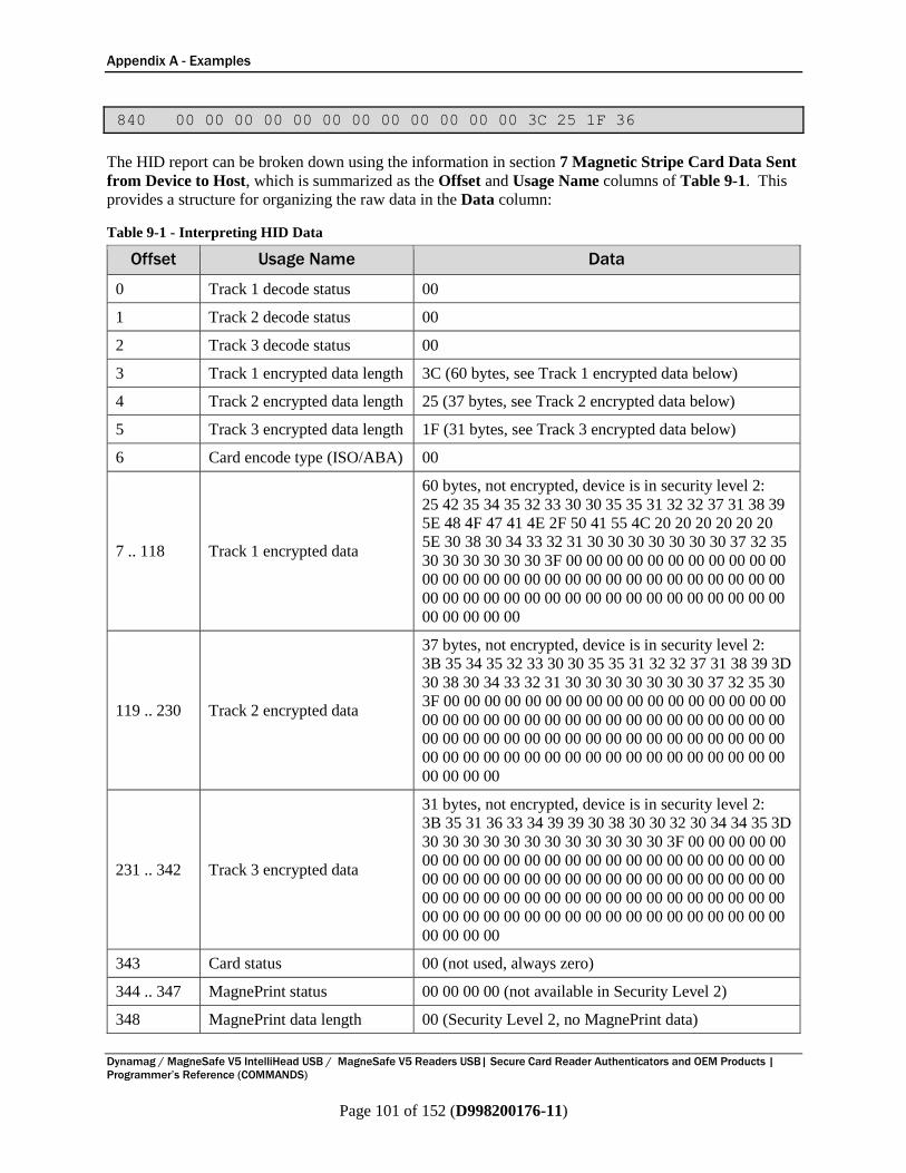
Appendix A - Examples
Dynamag / MagneSafe V5 IntelliHead USB / MagneSafe V5 Readers USB| Secure Card Reader Authenticators and OEM Products |
Programmer’s Reference (COMMANDS)
Page 101 of 152 (D998200176-11)
840 00 00 00 00 00 00 00 00 00 00 00 00 3C 25 1F 36
The HID report can be broken down using the information in section 7 Magnetic Stripe Card Data Sent
from Device to Host, which is summarized as the Offset and Usage Name columns of Table 9-1. This
provides a structure for organizing the raw data in the Data column:
Table 9-1 - Interpreting HID Data
Offset Usage Name Data
0 Track 1 decode status 00
1 Track 2 decode status 00
2 Track 3 decode status 00
3 Track 1 encrypted data length 3C (60 bytes, see Track 1 encrypted data below)
4 Track 2 encrypted data length 25 (37 bytes, see Track 2 encrypted data below)
5 Track 3 encrypted data length 1F (31 bytes, see Track 3 encrypted data below)
6 Card encode type (ISO/ABA) 00
7 .. 118 Track 1 encrypted data
60 bytes, not encrypted, device is in security level 2:
25 42 35 34 35 32 33 30 30 35 35 31 32 32 37 31 38 39
5E 48 4F 47 41 4E 2F 50 41 55 4C 20 20 20 20 20 20
5E 30 38 30 34 33 32 31 30 30 30 30 30 30 30 37 32 35
30 30 30 30 30 30 3F 00 00 00 00 00 00 00 00 00 00 00
00 00 00 00 00 00 00 00 00 00 00 00 00 00 00 00 00 00
00 00 00 00 00 00 00 00 00 00 00 00 00 00 00 00 00 00
00 00 00 00 00
119 .. 230 Track 2 encrypted data
37 bytes, not encrypted, device is in security level 2:
3B 35 34 35 32 33 30 30 35 35 31 32 32 37 31 38 39 3D
30 38 30 34 33 32 31 30 30 30 30 30 30 30 37 32 35 30
3F 00 00 00 00 00 00 00 00 00 00 00 00 00 00 00 00 00
00 00 00 00 00 00 00 00 00 00 00 00 00 00 00 00 00 00
00 00 00 00 00 00 00 00 00 00 00 00 00 00 00 00 00 00
00 00 00 00 00 00 00 00 00 00 00 00 00 00 00 00 00 00
00 00 00 00
231 .. 342 Track 3 encrypted data
31 bytes, not encrypted, device is in security level 2:
3B 35 31 36 33 34 39 39 30 38 30 30 32 30 34 34 35 3D
30 30 30 30 30 30 30 30 30 30 30 30 3F 00 00 00 00 00
00 00 00 00 00 00 00 00 00 00 00 00 00 00 00 00 00 00
00 00 00 00 00 00 00 00 00 00 00 00 00 00 00 00 00 00
00 00 00 00 00 00 00 00 00 00 00 00 00 00 00 00 00 00
00 00 00 00 00 00 00 00 00 00 00 00 00 00 00 00 00 00
00 00 00 00
343 Card status 00 (not used, always zero)
344 .. 347 MagnePrint status 00 00 00 00 (not available in Security Level 2)
348 MagnePrint data length 00 (Security Level 2, no MagnePrint data)
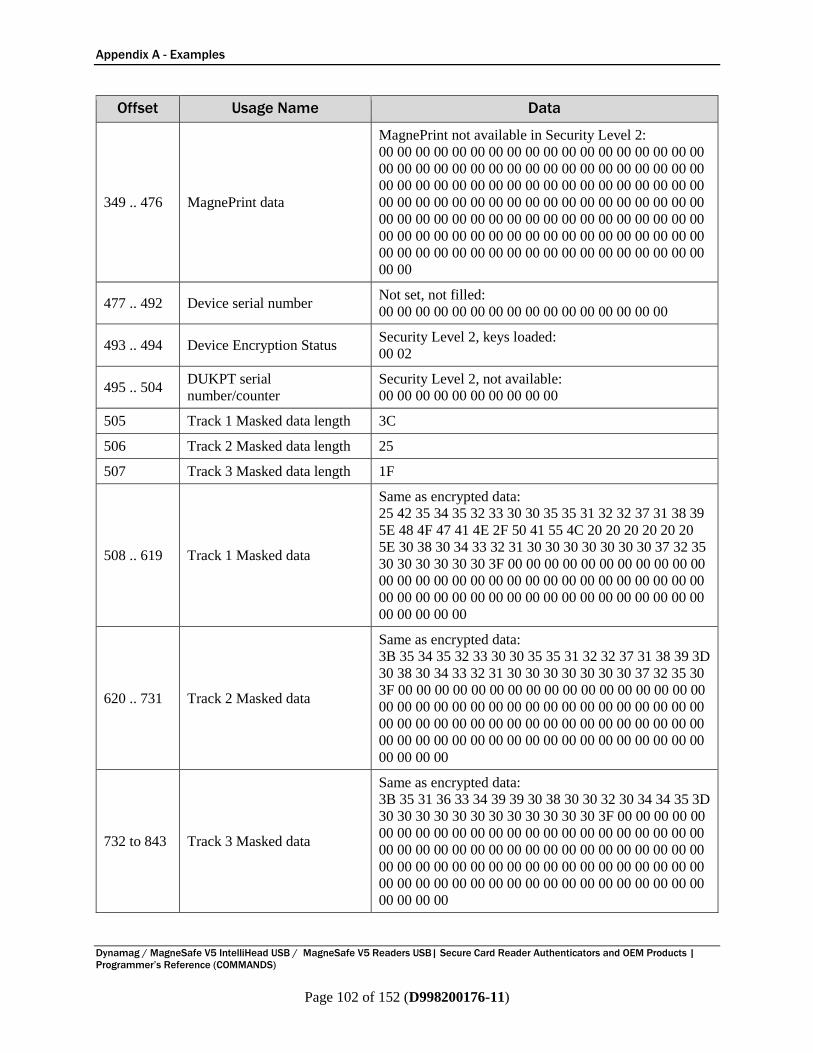
Appendix A - Examples
Dynamag / MagneSafe V5 IntelliHead USB / MagneSafe V5 Readers USB| Secure Card Reader Authenticators and OEM Products |
Programmer’s Reference (COMMANDS)
Page 102 of 152 (D998200176-11)
Offset Usage Name Data
349 .. 476 MagnePrint data
MagnePrint not available in Security Level 2:
00 00 00 00 00 00 00 00 00 00 00 00 00 00 00 00 00 00
00 00 00 00 00 00 00 00 00 00 00 00 00 00 00 00 00 00
00 00 00 00 00 00 00 00 00 00 00 00 00 00 00 00 00 00
00 00 00 00 00 00 00 00 00 00 00 00 00 00 00 00 00 00
00 00 00 00 00 00 00 00 00 00 00 00 00 00 00 00 00 00
00 00 00 00 00 00 00 00 00 00 00 00 00 00 00 00 00 00
00 00 00 00 00 00 00 00 00 00 00 00 00 00 00 00 00 00
00 00
477 .. 492 Device serial number Not set, not filled:
00 00 00 00 00 00 00 00 00 00 00 00 00 00 00 00
493 .. 494 Device Encryption Status Security Level 2, keys loaded:
00 02
495 .. 504 DUKPT serial
number/counter
Security Level 2, not available:
00 00 00 00 00 00 00 00 00 00
505 Track 1 Masked data length 3C
506 Track 2 Masked data length 25
507 Track 3 Masked data length 1F
508 .. 619 Track 1 Masked data
Same as encrypted data:
25 42 35 34 35 32 33 30 30 35 35 31 32 32 37 31 38 39
5E 48 4F 47 41 4E 2F 50 41 55 4C 20 20 20 20 20 20
5E 30 38 30 34 33 32 31 30 30 30 30 30 30 30 37 32 35
30 30 30 30 30 30 3F 00 00 00 00 00 00 00 00 00 00 00
00 00 00 00 00 00 00 00 00 00 00 00 00 00 00 00 00 00
00 00 00 00 00 00 00 00 00 00 00 00 00 00 00 00 00 00
00 00 00 00 00
620 .. 731 Track 2 Masked data
Same as encrypted data:
3B 35 34 35 32 33 30 30 35 35 31 32 32 37 31 38 39 3D
30 38 30 34 33 32 31 30 30 30 30 30 30 30 37 32 35 30
3F 00 00 00 00 00 00 00 00 00 00 00 00 00 00 00 00 00
00 00 00 00 00 00 00 00 00 00 00 00 00 00 00 00 00 00
00 00 00 00 00 00 00 00 00 00 00 00 00 00 00 00 00 00
00 00 00 00 00 00 00 00 00 00 00 00 00 00 00 00 00 00
00 00 00 00
732 to 843 Track 3 Masked data
Same as encrypted data:
3B 35 31 36 33 34 39 39 30 38 30 30 32 30 34 34 35 3D
30 30 30 30 30 30 30 30 30 30 30 30 3F 00 00 00 00 00
00 00 00 00 00 00 00 00 00 00 00 00 00 00 00 00 00 00
00 00 00 00 00 00 00 00 00 00 00 00 00 00 00 00 00 00
00 00 00 00 00 00 00 00 00 00 00 00 00 00 00 00 00 00
00 00 00 00 00 00 00 00 00 00 00 00 00 00 00 00 00 00
00 00 00 00
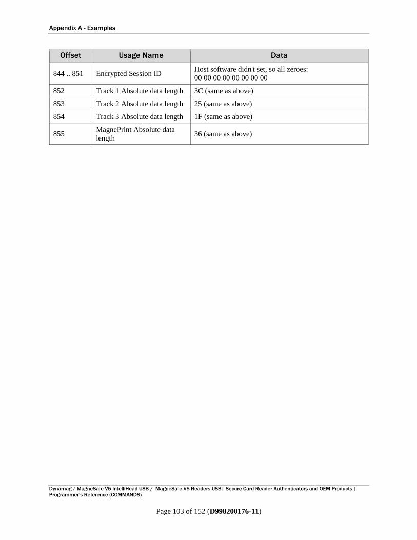
Appendix A - Examples
Dynamag / MagneSafe V5 IntelliHead USB / MagneSafe V5 Readers USB| Secure Card Reader Authenticators and OEM Products |
Programmer’s Reference (COMMANDS)
Page 103 of 152 (D998200176-11)
Offset Usage Name Data
844 .. 851 Encrypted Session ID Host software didn't set, so all zeroes:
00 00 00 00 00 00 00 00
852 Track 1 Absolute data length 3C (same as above)
853 Track 2 Absolute data length 25 (same as above)
854 Track 3 Absolute data length 1F (same as above)
855 MagnePrint Absolute data
length 36 (same as above)
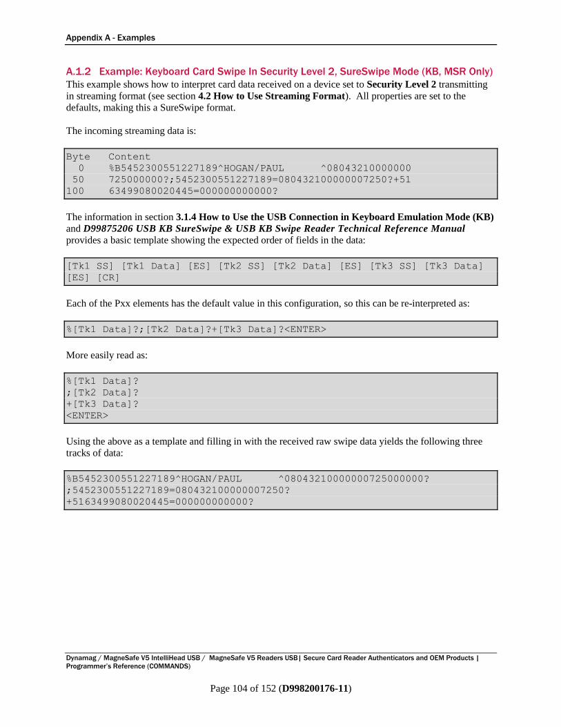
Appendix A - Examples
Dynamag / MagneSafe V5 IntelliHead USB / MagneSafe V5 Readers USB| Secure Card Reader Authenticators and OEM Products |
Programmer’s Reference (COMMANDS)
Page 104 of 152 (D998200176-11)
A.1.2 Example: Keyboard Card Swipe In Security Level 2, SureSwipe Mode (KB, MSR Only)
This example shows how to interpret card data received on a device set to Security Level 2 transmitting
in streaming format (see section 4.2 How to Use Streaming Format). All properties are set to the
defaults, making this a SureSwipe format.
The incoming streaming data is:
Byte Content
0 %B5452300551227189^HOGAN/PAUL ^08043210000000
50 725000000?;5452300551227189=080432100000007250?+51
100 63499080020445=000000000000?
The information in section 3.1.4 How to Use the USB Connection in Keyboard Emulation Mode (KB)
and D99875206 USB KB SureSwipe & USB KB Swipe Reader Technical Reference Manual
provides a basic template showing the expected order of fields in the data:
[Tk1 SS] [Tk1 Data] [ES] [Tk2 SS] [Tk2 Data] [ES] [Tk3 SS] [Tk3 Data]
[ES] [CR]
Each of the Pxx elements has the default value in this configuration, so this can be re-interpreted as:
%[Tk1 Data]?;[Tk2 Data]?+[Tk3 Data]?<ENTER>
More easily read as:
%[Tk1 Data]?
;[Tk2 Data]?
+[Tk3 Data]?
<ENTER>
Using the above as a template and filling in with the received raw swipe data yields the following three
tracks of data:
%B5452300551227189^HOGAN/PAUL ^08043210000000725000000?
;5452300551227189=080432100000007250?
+5163499080020445=000000000000?
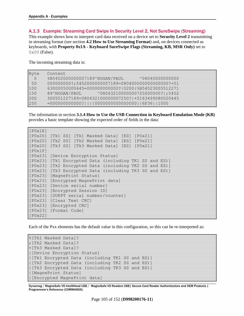
Appendix A - Examples
Dynamag / MagneSafe V5 IntelliHead USB / MagneSafe V5 Readers USB| Secure Card Reader Authenticators and OEM Products |
Programmer’s Reference (COMMANDS)
Page 105 of 152 (D998200176-11)
A.1.3 Example: Streaming Card Swipe In Security Level 2, Not SureSwipe (Streaming)
This example shows how to interpret card data received on a device set to Security Level 2 transmitting
in streaming format (see section 4.2 How to Use Streaming Format) and, on devices connected as
keyboards, with Property 0x1A - Keyboard SureSwipe Flags (Streaming, KB, MSR Only) set to
0x00 (False).
The incoming streaming data is:
Byte Content
0 %B5452000000007189^HOGAN/PAUL ^08040000000000
50 000000000?;5452000000007189=080400000000000000?+51
100 63000050000445=000000000000?|0200|%B54523005512271
150 89^HOGAN/PAUL ^08043210000000725000000?|;5452
200 300551227189=080432100000007250?|+5163499080020445
250 =000000000000?||||0000000000000000||6F36||1000
The information in section 3.1.4 How to Use the USB Connection in Keyboard Emulation Mode (KB)
provides a basic template showing the expected order of fields in the data:
[P0x1E]
[P0x20] [Tk1 SS] [Tk1 Masked Data] [ES] [P0x21]
[P0x20] [Tk2 SS] [Tk2 Masked Data] [ES] [P0x21]
[P0x20] [Tk3 SS] [Tk3 Masked Data] [ES] [P0x21]
[P0x1F]
[P0x23] [Device Encryption Status]
[P0x23] [Tk1 Encrypted Data (including TK1 SS and ES)]
[P0x23] [Tk2 Encrypted Data (including TK2 SS and ES)]
[P0x23] [Tk3 Encrypted Data (including TK3 SS and ES)]
[P0x23] [MagnePrint Status]
[P0x23] [Encrypted MagnePrint data]
[P0x23] [Device serial number]
[P0x23] [Encrypted Session ID]
[P0x23] [DUKPT serial number/counter]
[P0x23] [Clear Text CRC]
[P0x23] [Encrypted CRC]
[P0x23] [Format Code]
[P0x22]
Each of the Pxx elements has the default value in this configuration, so this can be re-interpreted as:
%[Tk1 Masked Data]?
;[Tk2 Masked Data]?
+[Tk3 Masked Data]?
|[Device Encryption Status]
|[Tk1 Encrypted Data (including TK1 SS and ES)]
|[Tk2 Encrypted Data (including TK2 SS and ES)]
|[Tk3 Encrypted Data (including TK3 SS and ES)]
|[MagnePrint Status]
|[Encrypted MagnePrint data]
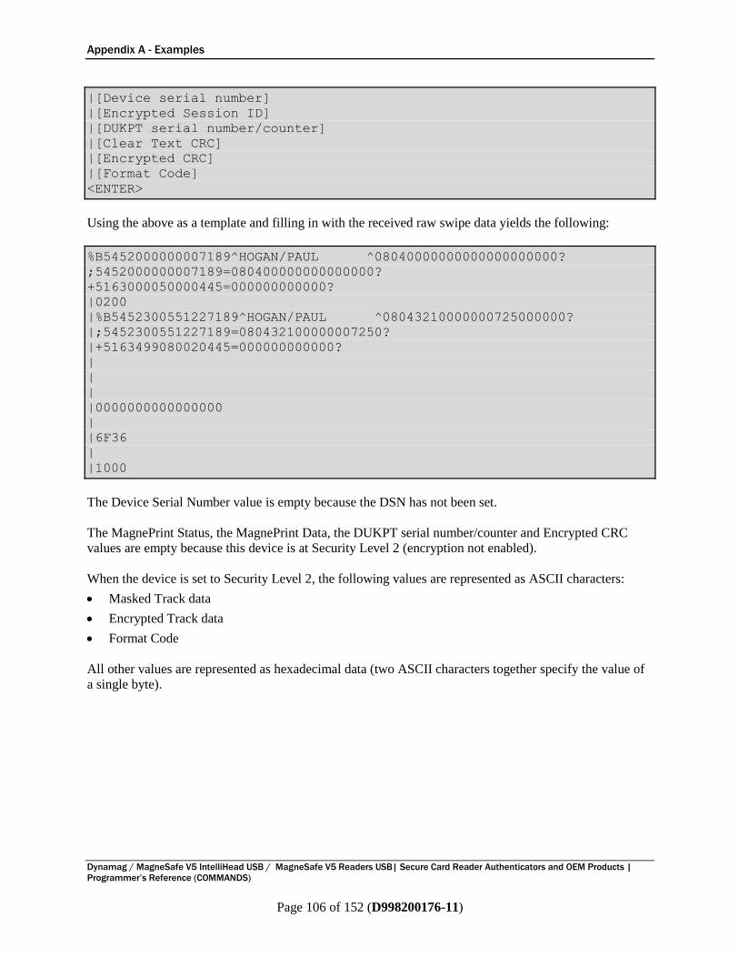
Appendix A - Examples
Dynamag / MagneSafe V5 IntelliHead USB / MagneSafe V5 Readers USB| Secure Card Reader Authenticators and OEM Products |
Programmer’s Reference (COMMANDS)
Page 106 of 152 (D998200176-11)
|[Device serial number]
|[Encrypted Session ID]
|[DUKPT serial number/counter]
|[Clear Text CRC]
|[Encrypted CRC]
|[Format Code]
<ENTER>
Using the above as a template and filling in with the received raw swipe data yields the following:
%B5452000000007189^HOGAN/PAUL ^08040000000000000000000?
;5452000000007189=080400000000000000?
+5163000050000445=000000000000?
|0200
|%B5452300551227189^HOGAN/PAUL ^08043210000000725000000?
|;5452300551227189=080432100000007250?
|+5163499080020445=000000000000?
|
|
|
|0000000000000000
|
|6F36
|
|1000
The Device Serial Number value is empty because the DSN has not been set.
The MagnePrint Status, the MagnePrint Data, the DUKPT serial number/counter and Encrypted CRC
values are empty because this device is at Security Level 2 (encryption not enabled).
When the device is set to Security Level 2, the following values are represented as ASCII characters:
Masked Track data
Encrypted Track data
Format Code
All other values are represented as hexadecimal data (two ASCII characters together specify the value of
a single byte).
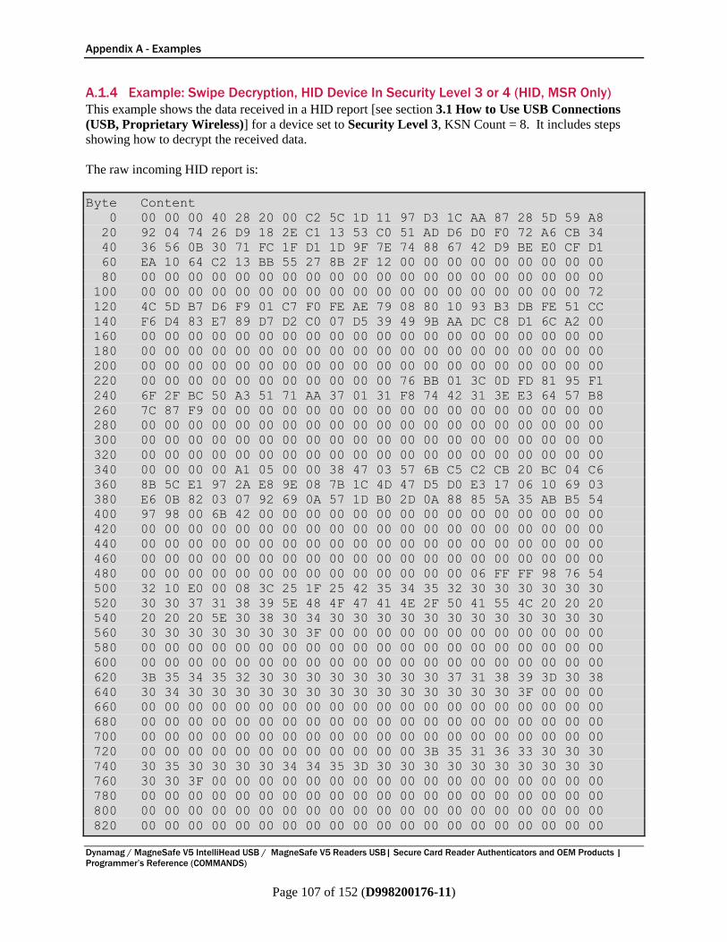
Appendix A - Examples
Dynamag / MagneSafe V5 IntelliHead USB / MagneSafe V5 Readers USB| Secure Card Reader Authenticators and OEM Products |
Programmer’s Reference (COMMANDS)
Page 107 of 152 (D998200176-11)
A.1.4 Example: Swipe Decryption, HID Device In Security Level 3 or 4 (HID, MSR Only)
This example shows the data received in a HID report [see section 3.1 How to Use USB Connections
(USB, Proprietary Wireless)] for a device set to Security Level 3, KSN Count = 8. It includes steps
showing how to decrypt the received data.
The raw incoming HID report is:
Byte Content
0 00 00 00 40 28 20 00 C2 5C 1D 11 97 D3 1C AA 87 28 5D 59 A8
20 92 04 74 26 D9 18 2E C1 13 53 C0 51 AD D6 D0 F0 72 A6 CB 34
40 36 56 0B 30 71 FC 1F D1 1D 9F 7E 74 88 67 42 D9 BE E0 CF D1
60 EA 10 64 C2 13 BB 55 27 8B 2F 12 00 00 00 00 00 00 00 00 00
80 00 00 00 00 00 00 00 00 00 00 00 00 00 00 00 00 00 00 00 00
100 00 00 00 00 00 00 00 00 00 00 00 00 00 00 00 00 00 00 00 72
120 4C 5D B7 D6 F9 01 C7 F0 FE AE 79 08 80 10 93 B3 DB FE 51 CC
140 F6 D4 83 E7 89 D7 D2 C0 07 D5 39 49 9B AA DC C8 D1 6C A2 00
160 00 00 00 00 00 00 00 00 00 00 00 00 00 00 00 00 00 00 00 00
180 00 00 00 00 00 00 00 00 00 00 00 00 00 00 00 00 00 00 00 00
200 00 00 00 00 00 00 00 00 00 00 00 00 00 00 00 00 00 00 00 00
220 00 00 00 00 00 00 00 00 00 00 00 76 BB 01 3C 0D FD 81 95 F1
240 6F 2F BC 50 A3 51 71 AA 37 01 31 F8 74 42 31 3E E3 64 57 B8
260 7C 87 F9 00 00 00 00 00 00 00 00 00 00 00 00 00 00 00 00 00
280 00 00 00 00 00 00 00 00 00 00 00 00 00 00 00 00 00 00 00 00
300 00 00 00 00 00 00 00 00 00 00 00 00 00 00 00 00 00 00 00 00
320 00 00 00 00 00 00 00 00 00 00 00 00 00 00 00 00 00 00 00 00
340 00 00 00 00 A1 05 00 00 38 47 03 57 6B C5 C2 CB 20 BC 04 C6
360 8B 5C E1 97 2A E8 9E 08 7B 1C 4D 47 D5 D0 E3 17 06 10 69 03
380 E6 0B 82 03 07 92 69 0A 57 1D B0 2D 0A 88 85 5A 35 AB B5 54
400 97 98 00 6B 42 00 00 00 00 00 00 00 00 00 00 00 00 00 00 00
420 00 00 00 00 00 00 00 00 00 00 00 00 00 00 00 00 00 00 00 00
440 00 00 00 00 00 00 00 00 00 00 00 00 00 00 00 00 00 00 00 00
460 00 00 00 00 00 00 00 00 00 00 00 00 00 00 00 00 00 00 00 00
480 00 00 00 00 00 00 00 00 00 00 00 00 00 00 06 FF FF 98 76 54
500 32 10 E0 00 08 3C 25 1F 25 42 35 34 35 32 30 30 30 30 30 30
520 30 30 37 31 38 39 5E 48 4F 47 41 4E 2F 50 41 55 4C 20 20 20
540 20 20 20 5E 30 38 30 34 30 30 30 30 30 30 30 30 30 30 30 30
560 30 30 30 30 30 30 30 3F 00 00 00 00 00 00 00 00 00 00 00 00
580 00 00 00 00 00 00 00 00 00 00 00 00 00 00 00 00 00 00 00 00
600 00 00 00 00 00 00 00 00 00 00 00 00 00 00 00 00 00 00 00 00
620 3B 35 34 35 32 30 30 30 30 30 30 30 30 37 31 38 39 3D 30 38
640 30 34 30 30 30 30 30 30 30 30 30 30 30 30 30 30 3F 00 00 00
660 00 00 00 00 00 00 00 00 00 00 00 00 00 00 00 00 00 00 00 00
680 00 00 00 00 00 00 00 00 00 00 00 00 00 00 00 00 00 00 00 00
700 00 00 00 00 00 00 00 00 00 00 00 00 00 00 00 00 00 00 00 00
720 00 00 00 00 00 00 00 00 00 00 00 00 3B 35 31 36 33 30 30 30
740 30 35 30 30 30 30 34 34 35 3D 30 30 30 30 30 30 30 30 30 30
760 30 30 3F 00 00 00 00 00 00 00 00 00 00 00 00 00 00 00 00 00
780 00 00 00 00 00 00 00 00 00 00 00 00 00 00 00 00 00 00 00 00
800 00 00 00 00 00 00 00 00 00 00 00 00 00 00 00 00 00 00 00 00
820 00 00 00 00 00 00 00 00 00 00 00 00 00 00 00 00 00 00 00 00

Appendix A - Examples
Dynamag / MagneSafe V5 IntelliHead USB / MagneSafe V5 Readers USB| Secure Card Reader Authenticators and OEM Products |
Programmer’s Reference (COMMANDS)
Page 108 of 152 (D998200176-11)
840 00 00 00 00 21 68 5F 15 8B 5C 6B E0 3C 25 1F 36
The HID report can be broken down using the information in section 7 Magnetic Stripe Card Data Sent
from Device to Host, which is summarized as the Offset and Usage Name columns of Table 9-2. This
provides a structure for organizing the raw data in the Data column:
Table 9-2 - Interpreting HID Data
Offset Usage Name Data
0 Track 1 decode status 00
1 Track 2 decode status 00
2 Track 3 decode status 00
3 Track 1 encrypted data length 40 (64 bytes, always in multiples of 8)
4 Track 2 encrypted data length 28 (40 bytes, always in multiples of 8)
5 Track 3 encrypted data length 20 (32 bytes, always in multiples of 8)
6 Card encode type (ISO/ABA) 00
7 to 118 Track 1 encrypted data
C2 5C 1D 11 97 D3 1C AA 87 28 5D 59 A8 92 04 74
26 D9 18 2E C1 13 53 C0 51 AD D6 D0 F0 72 A6 CB
34 36 56 0B 30 71 FC 1F D1 1D 9F 7E 74 88 67 42 D9
BE E0 CF D1 EA 10 64 C2 13 BB 55 27 8B 2F 12 00
00 00 00 00 00 00 00 00 00 00 00 00 00 00 00 00 00 00
00 00 00 00 00 00 00 00 00 00 00 00 00 00 00 00 00 00
00 00 00 00 00 00 00 00 00 00 00
119 to 230 Track 2 encrypted data
72 4C 5D B7 D6 F9 01 C7 F0 FE AE 79 08 80 10 93
B3 DB FE 51 CC F6 D4 83 E7 89 D7 D2 C0 07 D5 39
49 9B AA DC C8 D1 6C A2 00 00 00 00 00 00 00 00
00 00 00 00 00 00 00 00 00 00 00 00 00 00 00 00 00 00
00 00 00 00 00 00 00 00 00 00 00 00 00 00 00 00 00 00
00 00 00 00 00 00 00 00 00 00 00 00 00 00 00 00 00 00
00 00 00 00 00 00 00 00 00 00
231 to 342 Track 3 encrypted data
76 BB 01 3C 0D FD 81 95 F1 6F 2F BC 50 A3 51 71
AA 37 01 31 F8 74 42 31 3E E3 64 57 B8 7C 87 F9 00
00 00 00 00 00 00 00 00 00 00 00 00 00 00 00 00 00 00
00 00 00 00 00 00 00 00 00 00 00 00 00 00 00 00 00 00
00 00 00 00 00 00 00 00 00 00 00 00 00 00 00 00 00 00
00 00 00 00 00 00 00 00 00 00 00 00 00 00 00 00 00 00
00 00 00 00 00 00 00
343 Card status 00 (not used, always zero)
344 to 347 MagnePrint status A1 05 00 00
348 MagnePrint data length 38
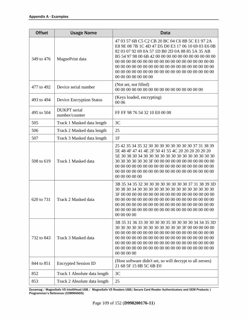
Appendix A - Examples
Dynamag / MagneSafe V5 IntelliHead USB / MagneSafe V5 Readers USB| Secure Card Reader Authenticators and OEM Products |
Programmer’s Reference (COMMANDS)
Page 109 of 152 (D998200176-11)
Offset Usage Name Data
349 to 476 MagnePrint data
47 03 57 6B C5 C2 CB 20 BC 04 C6 8B 5C E1 97 2A
E8 9E 08 7B 1C 4D 47 D5 D0 E3 17 06 10 69 03 E6 0B
82 03 07 92 69 0A 57 1D B0 2D 0A 88 85 5A 35 AB
B5 54 97 98 00 6B 42 00 00 00 00 00 00 00 00 00 00 00
00 00 00 00 00 00 00 00 00 00 00 00 00 00 00 00 00 00
00 00 00 00 00 00 00 00 00 00 00 00 00 00 00 00 00 00
00 00 00 00 00 00 00 00 00 00 00 00 00 00 00 00 00 00
00 00 00 00 00 00 00
477 to 492 Device serial number (Not set, not filled)
00 00 00 00 00 00 00 00 00 00 00 00 00 00 00 00
493 to 494 Device Encryption Status (Keys loaded, encrypting)
00 06
495 to 504 DUKPT serial
number/counter FF FF 98 76 54 32 10 E0 00 08
505 Track 1 Masked data length 3C
506 Track 2 Masked data length 25
507 Track 3 Masked data length 1F
508 to 619 Track 1 Masked data
25 42 35 34 35 32 30 30 30 30 30 30 30 30 37 31 38 39
5E 48 4F 47 41 4E 2F 50 41 55 4C 20 20 20 20 20 20
5E 30 38 30 34 30 30 30 30 30 30 30 30 30 30 30 30 30
30 30 30 30 30 30 3F 00 00 00 00 00 00 00 00 00 00 00
00 00 00 00 00 00 00 00 00 00 00 00 00 00 00 00 00 00
00 00 00 00 00 00 00 00 00 00 00 00 00 00 00 00 00 00
00 00 00 00 00
620 to 731 Track 2 Masked data
3B 35 34 35 32 30 30 30 30 30 30 30 30 37 31 38 39 3D
30 38 30 34 30 30 30 30 30 30 30 30 30 30 30 30 30 30
3F 00 00 00 00 00 00 00 00 00 00 00 00 00 00 00 00 00
00 00 00 00 00 00 00 00 00 00 00 00 00 00 00 00 00 00
00 00 00 00 00 00 00 00 00 00 00 00 00 00 00 00 00 00
00 00 00 00 00 00 00 00 00 00 00 00 00 00 00 00 00 00
00 00 00 00
732 to 843 Track 3 Masked data
3B 35 31 36 33 30 30 30 30 35 30 30 30 30 34 34 35 3D
30 30 30 30 30 30 30 30 30 30 30 30 3F 00 00 00 00 00
00 00 00 00 00 00 00 00 00 00 00 00 00 00 00 00 00 00
00 00 00 00 00 00 00 00 00 00 00 00 00 00 00 00 00 00
00 00 00 00 00 00 00 00 00 00 00 00 00 00 00 00 00 00
00 00 00 00 00 00 00 00 00 00 00 00 00 00 00 00 00 00
00 00 00 00
844 to 851 Encrypted Session ID (Host software didn't set, so will decrypt to all zeroes)
21 68 5F 15 8B 5C 6B E0
852 Track 1 Absolute data length 3C
853 Track 2 Absolute data length 25
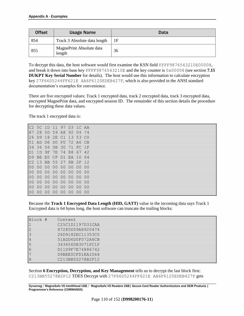
Appendix A - Examples
Dynamag / MagneSafe V5 IntelliHead USB / MagneSafe V5 Readers USB| Secure Card Reader Authenticators and OEM Products |
Programmer’s Reference (COMMANDS)
Page 110 of 152 (D998200176-11)
Offset Usage Name Data
854 Track 3 Absolute data length 1F
855 MagnePrint Absolute data
length 36
To decrypt this data, the host software would first examine the KSN field FFFF9876543210E00008,
and break it down into base key FFFF9876543210E and the key counter is 0x00008 (see section 7.15
DUKPT Key Serial Number for details). The host would use this information to calculate encryption
key 27F66D5244FF621E AA6F6120EDEB427F, which is also provided in the ANSI standard
documentation’s examples for convenience.
There are five encrypted values: Track 1 encrypted data, track 2 encrypted data, track 3 encrypted data,
encrypted MagnePrint data, and encrypted session ID. The remainder of this section details the procedure
for decrypting these data values.
The track 1 encrypted data is:
C2 5C 1D 11 97 D3 1C AA
87 28 5D 59 A8 92 04 74
26 D9 18 2E C1 13 53 C0
51 AD D6 D0 F0 72 A6 CB
34 36 56 0B 30 71 FC 1F
D1 1D 9F 7E 74 88 67 42
D9 BE E0 CF D1 EA 10 64
C2 13 BB 55 27 8B 2F 12
00 00 00 00 00 00 00 00
00 00 00 00 00 00 00 00
00 00 00 00 00 00 00 00
00 00 00 00 00 00 00 00
00 00 00 00 00 00 00 00
00 00 00 00 00 00 00 00
Because the Track 1 Encrypted Data Length (HID, GATT) value in the incoming data says Track 1
Encrypted data is 64 bytes long, the host software can truncate the trailing blocks:
Block # Content
1 C25C1D1197D31CAA
2 87285D59A8920474
3 26D9182EC11353C0
4 51ADD6D0F072A6CB
5 3436560B3071FC1F
6 D11D9F7E74886742
7 D9BEE0CFD1EA1064
8 C213BB55278B2F12
Section 6 Encryption, Decryption, and Key Management tells us to decrypt the last block first:
C213BB55278B2F12 TDES Decrypt with 27F66D5244FF621E AA6F6120EDEB427F gets
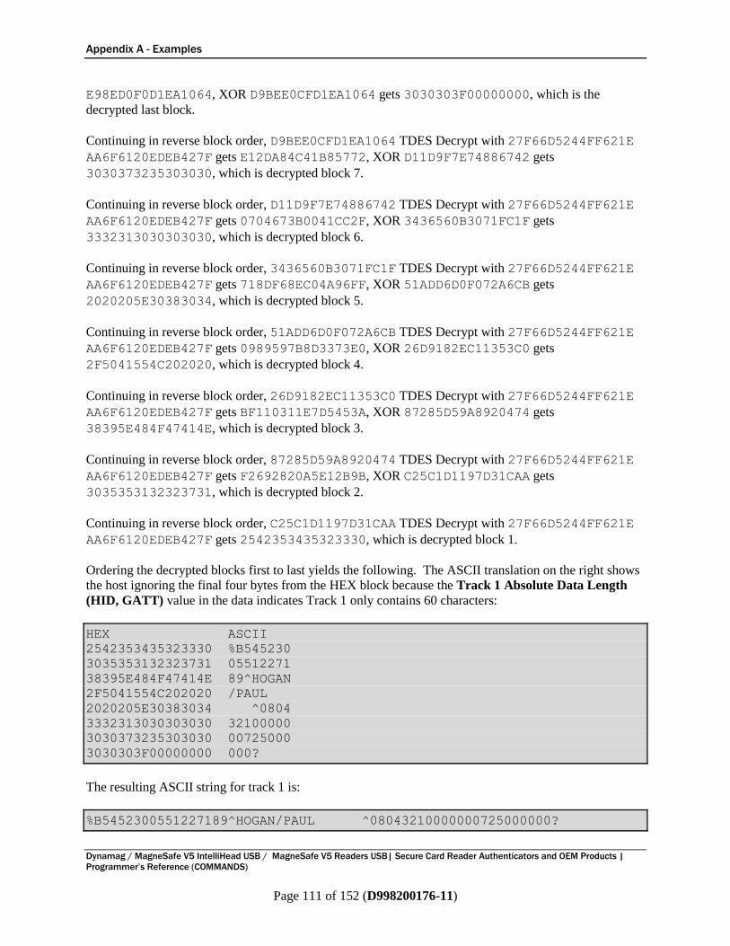
Appendix A - Examples
Dynamag / MagneSafe V5 IntelliHead USB / MagneSafe V5 Readers USB| Secure Card Reader Authenticators and OEM Products |
Programmer’s Reference (COMMANDS)
Page 111 of 152 (D998200176-11)
E98ED0F0D1EA1064, XOR D9BEE0CFD1EA1064 gets 3030303F00000000, which is the
decrypted last block.
Continuing in reverse block order, D9BEE0CFD1EA1064 TDES Decrypt with 27F66D5244FF621E
AA6F6120EDEB427F gets E12DA84C41B85772, XOR D11D9F7E74886742 gets
3030373235303030, which is decrypted block 7.
Continuing in reverse block order, D11D9F7E74886742 TDES Decrypt with 27F66D5244FF621E
AA6F6120EDEB427F gets 0704673B0041CC2F, XOR 3436560B3071FC1F gets
3332313030303030, which is decrypted block 6.
Continuing in reverse block order, 3436560B3071FC1F TDES Decrypt with 27F66D5244FF621E
AA6F6120EDEB427F gets 718DF68EC04A96FF, XOR 51ADD6D0F072A6CB gets
2020205E30383034, which is decrypted block 5.
Continuing in reverse block order, 51ADD6D0F072A6CB TDES Decrypt with 27F66D5244FF621E
AA6F6120EDEB427F gets 0989597B8D3373E0, XOR 26D9182EC11353C0 gets
2F5041554C202020, which is decrypted block 4.
Continuing in reverse block order, 26D9182EC11353C0 TDES Decrypt with 27F66D5244FF621E
AA6F6120EDEB427F gets BF110311E7D5453A, XOR 87285D59A8920474 gets
38395E484F47414E, which is decrypted block 3.
Continuing in reverse block order, 87285D59A8920474 TDES Decrypt with 27F66D5244FF621E
AA6F6120EDEB427F gets F2692820A5E12B9B, XOR C25C1D1197D31CAA gets
3035353132323731, which is decrypted block 2.
Continuing in reverse block order, C25C1D1197D31CAA TDES Decrypt with 27F66D5244FF621E
AA6F6120EDEB427F gets 2542353435323330, which is decrypted block 1.
Ordering the decrypted blocks first to last yields the following. The ASCII translation on the right shows
the host ignoring the final four bytes from the HEX block because the Track 1 Absolute Data Length
(HID, GATT) value in the data indicates Track 1 only contains 60 characters:
HEX ASCII
2542353435323330 %B545230
3035353132323731 05512271
38395E484F47414E 89^HOGAN
2F5041554C202020 /PAUL
2020205E30383034 ^0804
3332313030303030 32100000
3030373235303030 00725000
3030303F00000000 000?
The resulting ASCII string for track 1 is:
%B5452300551227189^HOGAN/PAUL ^08043210000000725000000?
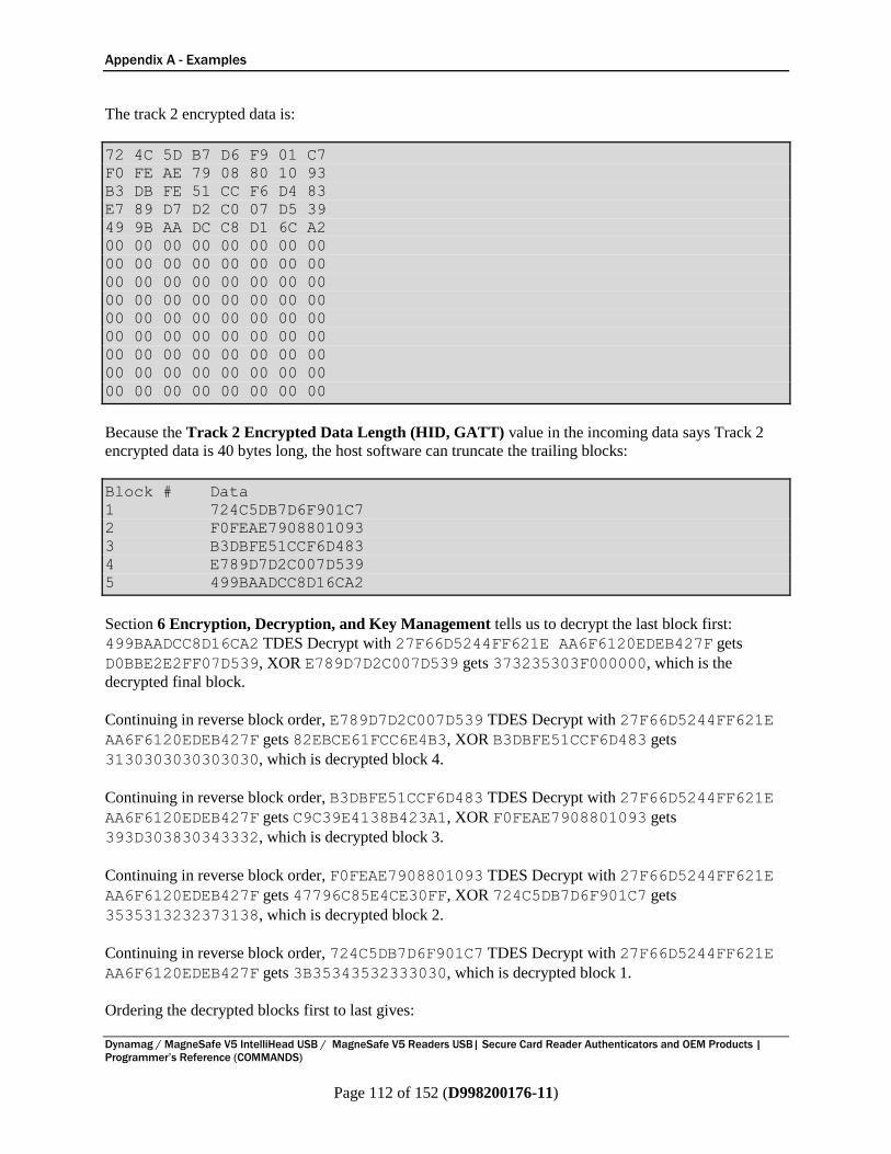
Appendix A - Examples
Dynamag / MagneSafe V5 IntelliHead USB / MagneSafe V5 Readers USB| Secure Card Reader Authenticators and OEM Products |
Programmer’s Reference (COMMANDS)
Page 112 of 152 (D998200176-11)
The track 2 encrypted data is:
72 4C 5D B7 D6 F9 01 C7
F0 FE AE 79 08 80 10 93
B3 DB FE 51 CC F6 D4 83
E7 89 D7 D2 C0 07 D5 39
49 9B AA DC C8 D1 6C A2
00 00 00 00 00 00 00 00
00 00 00 00 00 00 00 00
00 00 00 00 00 00 00 00
00 00 00 00 00 00 00 00
00 00 00 00 00 00 00 00
00 00 00 00 00 00 00 00
00 00 00 00 00 00 00 00
00 00 00 00 00 00 00 00
00 00 00 00 00 00 00 00
Because the Track 2 Encrypted Data Length (HID, GATT) value in the incoming data says Track 2
encrypted data is 40 bytes long, the host software can truncate the trailing blocks:
Block # Data
1 724C5DB7D6F901C7
2 F0FEAE7908801093
3 B3DBFE51CCF6D483
4 E789D7D2C007D539
5 499BAADCC8D16CA2
Section 6 Encryption, Decryption, and Key Management tells us to decrypt the last block first:
499BAADCC8D16CA2 TDES Decrypt with 27F66D5244FF621E AA6F6120EDEB427F gets
D0BBE2E2FF07D539, XOR E789D7D2C007D539 gets 373235303F000000, which is the
decrypted final block.
Continuing in reverse block order, E789D7D2C007D539 TDES Decrypt with 27F66D5244FF621E
AA6F6120EDEB427F gets 82EBCE61FCC6E4B3, XOR B3DBFE51CCF6D483 gets
3130303030303030, which is decrypted block 4.
Continuing in reverse block order, B3DBFE51CCF6D483 TDES Decrypt with 27F66D5244FF621E
AA6F6120EDEB427F gets C9C39E4138B423A1, XOR F0FEAE7908801093 gets
393D303830343332, which is decrypted block 3.
Continuing in reverse block order, F0FEAE7908801093 TDES Decrypt with 27F66D5244FF621E
AA6F6120EDEB427F gets 47796C85E4CE30FF, XOR 724C5DB7D6F901C7 gets
3535313232373138, which is decrypted block 2.
Continuing in reverse block order, 724C5DB7D6F901C7 TDES Decrypt with 27F66D5244FF621E
AA6F6120EDEB427F gets 3B35343532333030, which is decrypted block 1.
Ordering the decrypted blocks first to last gives:
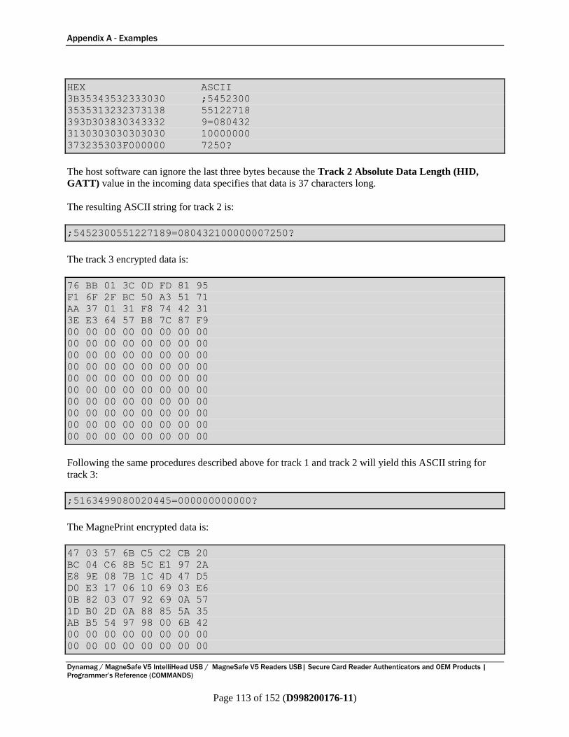
Appendix A - Examples
Dynamag / MagneSafe V5 IntelliHead USB / MagneSafe V5 Readers USB| Secure Card Reader Authenticators and OEM Products |
Programmer’s Reference (COMMANDS)
Page 113 of 152 (D998200176-11)
HEX ASCII
3B35343532333030 ;5452300
3535313232373138 55122718
393D303830343332 9=080432
3130303030303030 10000000
373235303F000000 7250?
The host software can ignore the last three bytes because the Track 2 Absolute Data Length (HID,
GATT) value in the incoming data specifies that data is 37 characters long.
The resulting ASCII string for track 2 is:
;5452300551227189=080432100000007250?
The track 3 encrypted data is:
76 BB 01 3C 0D FD 81 95
F1 6F 2F BC 50 A3 51 71
AA 37 01 31 F8 74 42 31
3E E3 64 57 B8 7C 87 F9
00 00 00 00 00 00 00 00
00 00 00 00 00 00 00 00
00 00 00 00 00 00 00 00
00 00 00 00 00 00 00 00
00 00 00 00 00 00 00 00
00 00 00 00 00 00 00 00
00 00 00 00 00 00 00 00
00 00 00 00 00 00 00 00
00 00 00 00 00 00 00 00
00 00 00 00 00 00 00 00
Following the same procedures described above for track 1 and track 2 will yield this ASCII string for
track 3:
;5163499080020445=000000000000?
The MagnePrint encrypted data is:
47 03 57 6B C5 C2 CB 20
BC 04 C6 8B 5C E1 97 2A
E8 9E 08 7B 1C 4D 47 D5
D0 E3 17 06 10 69 03 E6
0B 82 03 07 92 69 0A 57
1D B0 2D 0A 88 85 5A 35
AB B5 54 97 98 00 6B 42
00 00 00 00 00 00 00 00
00 00 00 00 00 00 00 00

Appendix A - Examples
Dynamag / MagneSafe V5 IntelliHead USB / MagneSafe V5 Readers USB| Secure Card Reader Authenticators and OEM Products |
Programmer’s Reference (COMMANDS)
Page 114 of 152 (D998200176-11)
00 00 00 00 00 00 00 00
00 00 00 00 00 00 00 00
00 00 00 00 00 00 00 00
00 00 00 00 00 00 00 00
00 00 00 00 00 00 00 00
00 00 00 00 00 00 00 00
00 00 00 00 00 00 00 00
Because the MagnePrint Data Length (HID, GATT) value in the incoming data says MagnePrint
encrypted data is 56 bytes long, the host software can truncate the trailing blocks:
Block # Data
1 4703576BC5C2CB20
2 BC04C68B5CE1972A
3 E89E087B1C4D47D5
4 D0E31706106903E6
5 0B82030792690A57
6 1DB02D0A88855A35
7 ABB5549798006B42
Section 6 Encryption, Decryption, and Key Management tells us to decrypt the last block first:
ABB5549798006B42 TDES Decrypt with 27F66D5244FF621E AA6F6120EDEB427F gets
D3B7EDDFD3045A35, XOR 1DB02D0A88855A35 gets CE07C0D55B810000, which is the
decrypted final block.
Continuing in reverse block order, 1DB02D0A88855A35 TDES Decrypt with 27F66D5244FF621E
AA6F6120EDEB427F gets B52307C37D314482, XOR 0B82030792690A57 gets
BEA104C4EF584ED5, which is decrypted block 6.
Continuing in reverse block order, 0B82030792690A57 TDES Decrypt with 27F66D5244FF621E
AA6F6120EDEB427F gets AF4EABEE4973E402, XOR D0E31706106903E6 gets
7FADBCE8591AE7E4, which is decrypted block 5.
Continuing in reverse block order, D0E31706106903E6 TDES Decrypt with 27F66D5244FF621E
AA6F6120EDEB427F gets 269870C3659D905E, XOR E89E087B1C4D47D5 gets
CE0678B879D0D78B, which is decrypted block 4.
Continuing in reverse block order, E89E087B1C4D47D5 TDES Decrypt with 27F66D5244FF621E
AA6F6120EDEB427F gets 7B8F912DAF1B3149, XOR BC04C68B5CE1972A gets
C78B57A6F3FAA663, which is decrypted block 3.
Continuing in reverse block order, BC04C68B5CE1972A TDES Decrypt with 27F66D5244FF621E
AA6F6120EDEB427F gets 078FD0419993F7B0, XOR 4703576BC5C2CB20 gets
408C872A5C513C90, which is decrypted block 2.
Continuing in reverse block order, 4703576BC5C2CB20 TDES Decrypt with 27F66D5244FF621E
AA6F6120EDEB427F gets 01000184EA10B939, which is decrypted block 1.
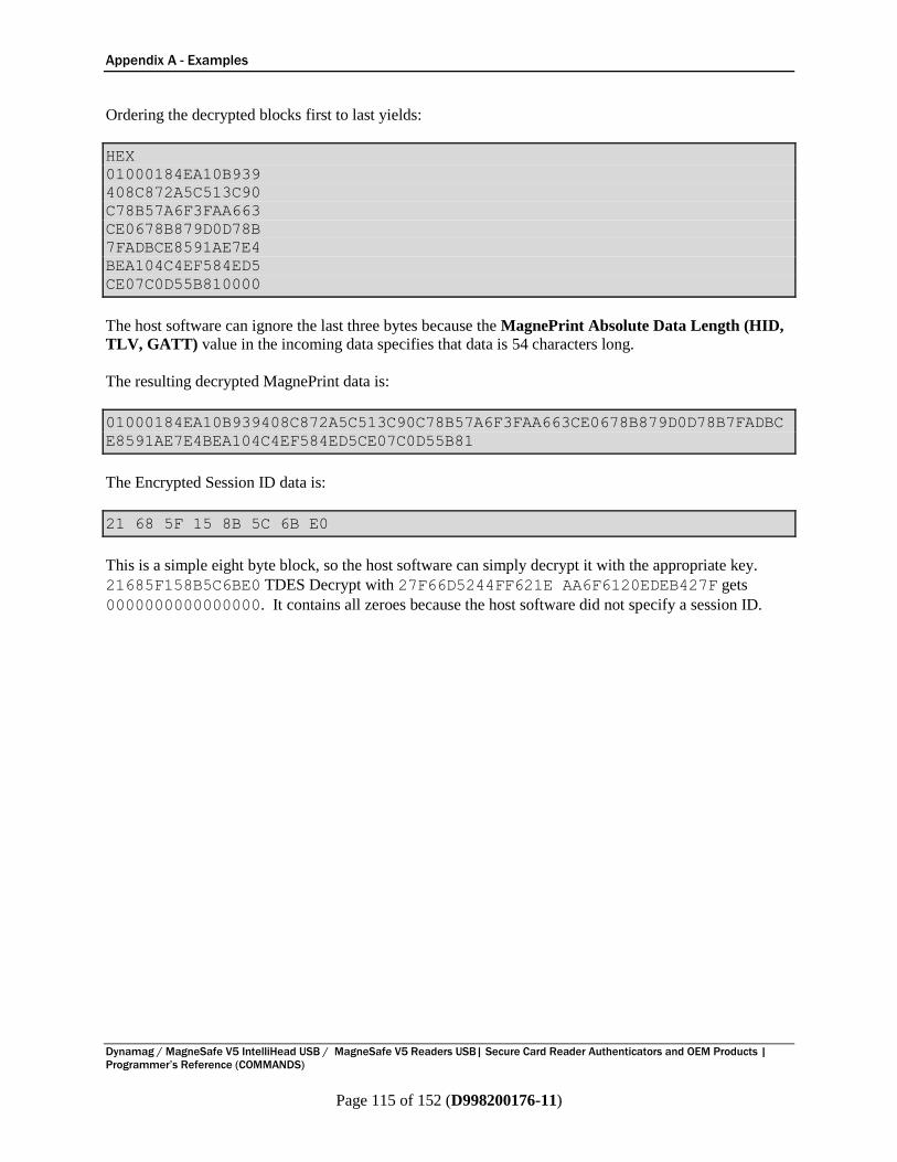
Appendix A - Examples
Dynamag / MagneSafe V5 IntelliHead USB / MagneSafe V5 Readers USB| Secure Card Reader Authenticators and OEM Products |
Programmer’s Reference (COMMANDS)
Page 115 of 152 (D998200176-11)
Ordering the decrypted blocks first to last yields:
HEX
01000184EA10B939
408C872A5C513C90
C78B57A6F3FAA663
CE0678B879D0D78B
7FADBCE8591AE7E4
BEA104C4EF584ED5
CE07C0D55B810000
The host software can ignore the last three bytes because the MagnePrint Absolute Data Length (HID,
TLV, GATT) value in the incoming data specifies that data is 54 characters long.
The resulting decrypted MagnePrint data is:
01000184EA10B939408C872A5C513C90C78B57A6F3FAA663CE0678B879D0D78B7FADBC
E8591AE7E4BEA104C4EF584ED5CE07C0D55B81
The Encrypted Session ID data is:
21 68 5F 15 8B 5C 6B E0
This is a simple eight byte block, so the host software can simply decrypt it with the appropriate key.
21685F158B5C6BE0 TDES Decrypt with 27F66D5244FF621E AA6F6120EDEB427F gets
0000000000000000. It contains all zeroes because the host software did not specify a session ID.
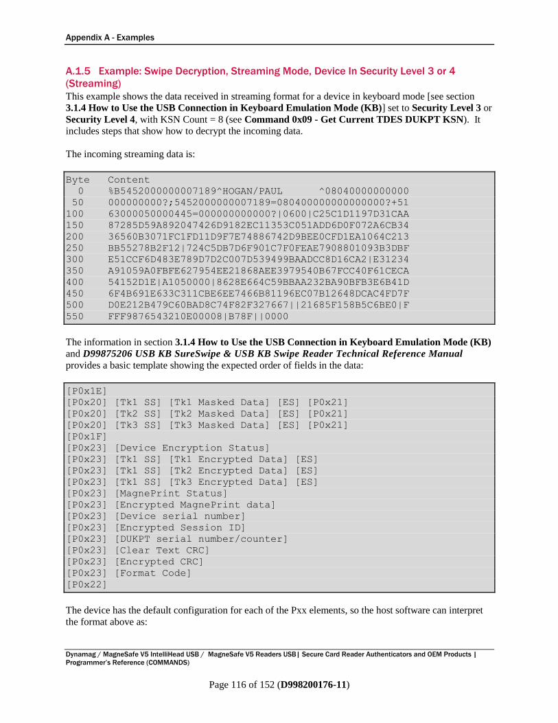
Appendix A - Examples
Dynamag / MagneSafe V5 IntelliHead USB / MagneSafe V5 Readers USB| Secure Card Reader Authenticators and OEM Products |
Programmer’s Reference (COMMANDS)
Page 116 of 152 (D998200176-11)
A.1.5 Example: Swipe Decryption, Streaming Mode, Device In Security Level 3 or 4
(Streaming)
This example shows the data received in streaming format for a device in keyboard mode [see section
3.1.4 How to Use the USB Connection in Keyboard Emulation Mode (KB)] set to Security Level 3 or
Security Level 4, with KSN Count = 8 (see Command 0x09 - Get Current TDES DUKPT KSN). It
includes steps that show how to decrypt the incoming data.
The incoming streaming data is:
Byte Content
0 %B5452000000007189^HOGAN/PAUL ^08040000000000
50 000000000?;5452000000007189=080400000000000000?+51
100 63000050000445=000000000000?|0600|C25C1D1197D31CAA
150 87285D59A892047426D9182EC11353C051ADD6D0F072A6CB34
200 36560B3071FC1FD11D9F7E74886742D9BEE0CFD1EA1064C213
250 BB55278B2F12|724C5DB7D6F901C7F0FEAE7908801093B3DBF
300 E51CCF6D483E789D7D2C007D539499BAADCC8D16CA2|E31234
350 A91059A0FBFE627954EE21868AEE3979540B67FCC40F61CECA
400 54152D1E|A1050000|8628E664C59BBAA232BA90BFB3E6B41D
450 6F4B691E633C311CBE6EE7466B81196EC07B12648DCAC4FD7F
500 D0E212B479C60BAD8C74F82F327667||21685F158B5C6BE0|F
550 FFF9876543210E00008|B78F||0000
The information in section 3.1.4 How to Use the USB Connection in Keyboard Emulation Mode (KB)
and D99875206 USB KB SureSwipe & USB KB Swipe Reader Technical Reference Manual
provides a basic template showing the expected order of fields in the data:
[P0x1E]
[P0x20] [Tk1 SS] [Tk1 Masked Data] [ES] [P0x21]
[P0x20] [Tk2 SS] [Tk2 Masked Data] [ES] [P0x21]
[P0x20] [Tk3 SS] [Tk3 Masked Data] [ES] [P0x21]
[P0x1F]
[P0x23] [Device Encryption Status]
[P0x23] [Tk1 SS] [Tk1 Encrypted Data] [ES]
[P0x23] [Tk1 SS] [Tk2 Encrypted Data] [ES]
[P0x23] [Tk1 SS] [Tk3 Encrypted Data] [ES]
[P0x23] [MagnePrint Status]
[P0x23] [Encrypted MagnePrint data]
[P0x23] [Device serial number]
[P0x23] [Encrypted Session ID]
[P0x23] [DUKPT serial number/counter]
[P0x23] [Clear Text CRC]
[P0x23] [Encrypted CRC]
[P0x23] [Format Code]
[P0x22]
The device has the default configuration for each of the Pxx elements, so the host software can interpret
the format above as:
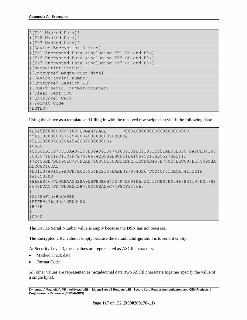
Appendix A - Examples
Dynamag / MagneSafe V5 IntelliHead USB / MagneSafe V5 Readers USB| Secure Card Reader Authenticators and OEM Products |
Programmer’s Reference (COMMANDS)
Page 117 of 152 (D998200176-11)
%[Tk1 Masked Data]?
;[Tk2 Masked Data]?
+[Tk3 Masked Data]?
|[Device Encryption Status]
|[Tk1 Encrypted Data (including TK1 SS and ES)]
|[Tk2 Encrypted Data (including TK2 SS and ES)]
|[Tk3 Encrypted Data (including TK3 SS and ES)]
|[MagnePrint Status]
|[Encrypted MagnePrint data]
|[Device serial number]
|[Encrypted Session ID]
|[DUKPT serial number/counter]
|[Clear Text CRC]
|[Encrypted CRC]
|[Format Code]
<ENTER>
Using the above as a template and filling in with the received raw swipe data yields the following data:
%B5452000000007189^HOGAN/PAUL ^08040000000000000000000?
;5452000000007189=080400000000000000?
+5163000050000445=000000000000?
|0600
|C25C1D1197D31CAA87285D59A892047426D9182EC11353C051ADD6D0F072A6CB34365
60B3071FC1FD11D9F7E74886742D9BEE0CFD1EA1064C213BB55278B2F12
|724C5DB7D6F901C7F0FEAE7908801093B3DBFE51CCF6D483E789D7D2C007D539499BA
ADCC8D16CA2
|E31234A91059A0FBFE627954EE21868AEE3979540B67FCC40F61CECA54152D1E
|A1050000
|8628E664C59BBAA232BA90BFB3E6B41D6F4B691E633C311CBE6EE7466B81196EC07B1
2648DCAC4FD7FD0E212B479C60BAD8C74F82F327667
|
|21685F158B5C6BE0
|FFFF9876543210E00008
|B78F
|
|0000
The Device Serial Number value is empty because the DSN has not been set.
The Encrypted CRC value is empty because the default configuration is to send it empty.
At Security Level 3, these values are represented as ASCII characters:
Masked Track data
Format Code
All other values are represented as hexadecimal data (two ASCII characters together specify the value of
a single byte).
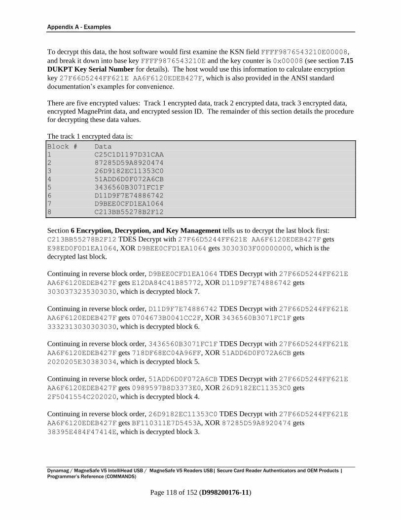
Appendix A - Examples
Dynamag / MagneSafe V5 IntelliHead USB / MagneSafe V5 Readers USB| Secure Card Reader Authenticators and OEM Products |
Programmer’s Reference (COMMANDS)
Page 118 of 152 (D998200176-11)
To decrypt this data, the host software would first examine the KSN field FFFF9876543210E00008,
and break it down into base key FFFF9876543210E and the key counter is 0x00008 (see section 7.15
DUKPT Key Serial Number for details). The host would use this information to calculate encryption
key 27F66D5244FF621E AA6F6120EDEB427F, which is also provided in the ANSI standard
documentation’s examples for convenience.
There are five encrypted values: Track 1 encrypted data, track 2 encrypted data, track 3 encrypted data,
encrypted MagnePrint data, and encrypted session ID. The remainder of this section details the procedure
for decrypting these data values.
The track 1 encrypted data is:
Block # Data
1 C25C1D1197D31CAA
2 87285D59A8920474
3 26D9182EC11353C0
4 51ADD6D0F072A6CB
5 3436560B3071FC1F
6 D11D9F7E74886742
7 D9BEE0CFD1EA1064
8 C213BB55278B2F12
Section 6 Encryption, Decryption, and Key Management tells us to decrypt the last block first:
C213BB55278B2F12 TDES Decrypt with 27F66D5244FF621E AA6F6120EDEB427F gets
E98ED0F0D1EA1064, XOR D9BEE0CFD1EA1064 gets 3030303F00000000, which is the
decrypted last block.
Continuing in reverse block order, D9BEE0CFD1EA1064 TDES Decrypt with 27F66D5244FF621E
AA6F6120EDEB427F gets E12DA84C41B85772, XOR D11D9F7E74886742 gets
3030373235303030, which is decrypted block 7.
Continuing in reverse block order, D11D9F7E74886742 TDES Decrypt with 27F66D5244FF621E
AA6F6120EDEB427F gets 0704673B0041CC2F, XOR 3436560B3071FC1F gets
3332313030303030, which is decrypted block 6.
Continuing in reverse block order, 3436560B3071FC1F TDES Decrypt with 27F66D5244FF621E
AA6F6120EDEB427F gets 718DF68EC04A96FF, XOR 51ADD6D0F072A6CB gets
2020205E30383034, which is decrypted block 5.
Continuing in reverse block order, 51ADD6D0F072A6CB TDES Decrypt with 27F66D5244FF621E
AA6F6120EDEB427F gets 0989597B8D3373E0, XOR 26D9182EC11353C0 gets
2F5041554C202020, which is decrypted block 4.
Continuing in reverse block order, 26D9182EC11353C0 TDES Decrypt with 27F66D5244FF621E
AA6F6120EDEB427F gets BF110311E7D5453A, XOR 87285D59A8920474 gets
38395E484F47414E, which is decrypted block 3.
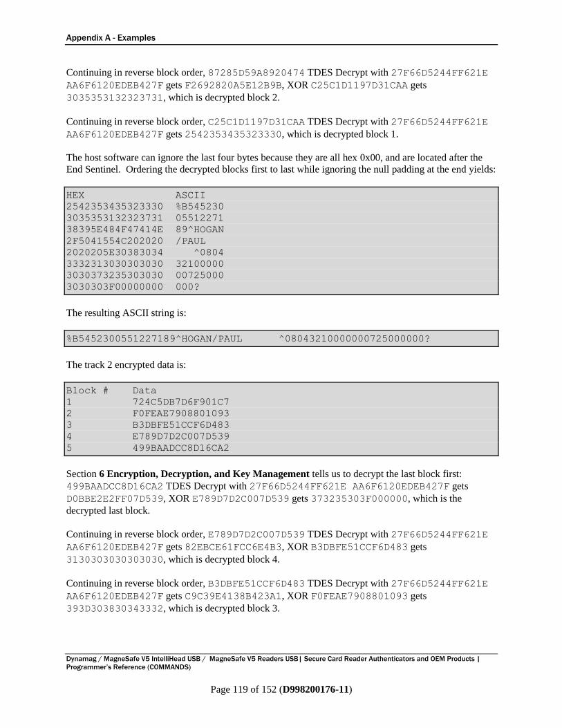
Appendix A - Examples
Dynamag / MagneSafe V5 IntelliHead USB / MagneSafe V5 Readers USB| Secure Card Reader Authenticators and OEM Products |
Programmer’s Reference (COMMANDS)
Page 119 of 152 (D998200176-11)
Continuing in reverse block order, 87285D59A8920474 TDES Decrypt with 27F66D5244FF621E
AA6F6120EDEB427F gets F2692820A5E12B9B, XOR C25C1D1197D31CAA gets
3035353132323731, which is decrypted block 2.
Continuing in reverse block order, C25C1D1197D31CAA TDES Decrypt with 27F66D5244FF621E
AA6F6120EDEB427F gets 2542353435323330, which is decrypted block 1.
The host software can ignore the last four bytes because they are all hex 0x00, and are located after the
End Sentinel. Ordering the decrypted blocks first to last while ignoring the null padding at the end yields:
HEX ASCII
2542353435323330 %B545230
3035353132323731 05512271
38395E484F47414E 89^HOGAN
2F5041554C202020 /PAUL
2020205E30383034 ^0804
3332313030303030 32100000
3030373235303030 00725000
3030303F00000000 000?
The resulting ASCII string is:
%B5452300551227189^HOGAN/PAUL ^08043210000000725000000?
The track 2 encrypted data is:
Block # Data
1 724C5DB7D6F901C7
2 F0FEAE7908801093
3 B3DBFE51CCF6D483
4 E789D7D2C007D539
5 499BAADCC8D16CA2
Section 6 Encryption, Decryption, and Key Management tells us to decrypt the last block first:
499BAADCC8D16CA2 TDES Decrypt with 27F66D5244FF621E AA6F6120EDEB427F gets
D0BBE2E2FF07D539, XOR E789D7D2C007D539 gets 373235303F000000, which is the
decrypted last block.
Continuing in reverse block order, E789D7D2C007D539 TDES Decrypt with 27F66D5244FF621E
AA6F6120EDEB427F gets 82EBCE61FCC6E4B3, XOR B3DBFE51CCF6D483 gets
3130303030303030, which is decrypted block 4.
Continuing in reverse block order, B3DBFE51CCF6D483 TDES Decrypt with 27F66D5244FF621E
AA6F6120EDEB427F gets C9C39E4138B423A1, XOR F0FEAE7908801093 gets
393D303830343332, which is decrypted block 3.

Appendix A - Examples
Dynamag / MagneSafe V5 IntelliHead USB / MagneSafe V5 Readers USB| Secure Card Reader Authenticators and OEM Products |
Programmer’s Reference (COMMANDS)
Page 120 of 152 (D998200176-11)
Continuing in reverse block order, F0FEAE7908801093 TDES Decrypt with 27F66D5244FF621E
AA6F6120EDEB427F gets 47796C85E4CE30FF, XOR 724C5DB7D6F901C7 gets
3535313232373138, which is decrypted block 2.
Continuing in reverse block order, 724C5DB7D6F901C7 TDES Decrypt with 27F66D5244FF621E
AA6F6120EDEB427F gets 3B35343532333030, which is decrypted block 1.
The host software can ignore the last four bytes because they are all hex 0x00, and are located after the
End Sentinel. Ordering the decrypted blocks first to last while ignoring the null padding at the end yields:
HEX ASCII
3B35343532333030 ;5452300
3535313232373138 55122718
393D303830343332 9=080432
3130303030303030 10000000
373235303F000000 7250?
The resulting ASCII string for track 2 is:
;5452300551227189=080432100000007250?
The track 3 encrypted data is:
Block # Data
1 E31234A91059A0FB
2 FE627954EE21868A
3 EE3979540B67FCC4
4 0F61CECA54152D1E
Section 6 Encryption, Decryption, and Key Management tells us to decrypt the last block first:
0F61CECA54152D1E TDES Decrypt with 27F66D5244FF621E AA6F6120EDEB427F gets
DE0949643B57C3C4, XOR EE3979540B67FCC4 gets 3030303030303F00, which is the
decrypted last block.
Continuing in reverse block order, EE3979540B67FCC4 TDES Decrypt with 27F66D5244FF621E
AA6F6120EDEB427F gets CB5F4964DE11B6BA, XOR FE627954EE21868A gets
353D303030303030, which is decrypted block 3.
Continuing in reverse block order, FE627954EE21868A TDES Decrypt with 27F66D5244FF621E
AA6F6120EDEB427F gets D32A0499226994CF, XOR E31234A91059A0FB gets
3038303032303434, which is decrypted block 2.
Continuing in reverse block order, E31234A91059A0FB TDES Decrypt with 27F66D5244FF621E
AA6F6120EDEB427F gets 2B35313633343939, which is decrypted block 1.
Ordering the decrypted blocks first to last gives:

Appendix A - Examples
Dynamag / MagneSafe V5 IntelliHead USB / MagneSafe V5 Readers USB| Secure Card Reader Authenticators and OEM Products |
Programmer’s Reference (COMMANDS)
Page 121 of 152 (D998200176-11)
HEX ASCII
2B35313633343939 +5163499
3038303032303434 08002044
353D303030303030 3=000000
3030303030303F00 000000?
The host software can ignore the last byte because it is hex 0x00 and is located after the End Sentinel.
The resulting ASCII string for track 3 is:
+5163499080020443=000000000000?
The MagnePrint data is:
Block # Data
1 8628E664C59BBAA2
2 32BA90BFB3E6B41D
3 6F4B691E633C311C
4 BE6EE7466B81196E
5 C07B12648DCAC4FD
6 7FD0E212B479C60B
7 AD8C74F82F327667
Section 6 Encryption, Decryption, and Key Management tells us to decrypt the last block first:
AD8C74F82F327667 TDES Decrypt with 27F66D5244FF621E AA6F6120EDEB427F gets
09162DCA11E5C60B, XOR 7FD0E212B479C60B gets 76C6CFD8A59C0000, which is the
decrypted last block.
Continuing in reverse block order, 7FD0E212B479C60B TDES Decrypt with 27F66D5244FF621E
AA6F6120EDEB427F gets AE81BFA4A2C80006, XOR C07B12648DCAC4FD gets
6EFAADC02F02C4FB, which is decrypted block 6.
Continuing in reverse block order, C07B12648DCAC4FD TDES Decrypt with 27F66D5244FF621E
AA6F6120EDEB427F gets AAC8D06ACCF27E6D, XOR BE6EE7466B81196E gets
14A6372CA7736703, which is decrypted block 5.
Continuing in reverse block order, BE6EE7466B81196E TDES Decrypt with 27F66D5244FF621E
AA6F6120EDEB427F gets 01D78CB7D1DAEA95, XOR 6F4B691E633C311C gets
6E9CE5A9B2E6DB89, which is decrypted block 4.
Continuing in reverse block order, 6F4B691E633C311C TDES Decrypt with 27F66D5244FF621E
AA6F6120EDEB427F gets 0D2620B051231748, XOR 32BA90BFB3E6B41D gets
3F9CB00FE2C5A355, which is decrypted block 3.
Continuing in reverse block order, 32BA90BFB3E6B41D TDES Decrypt with 27F66D5244FF621E
AA6F6120EDEB427F gets 41499B60A6AAD427, XOR 8628E664C59BBAA2 gets
C7617D0463316E85, which is decrypted block 2.
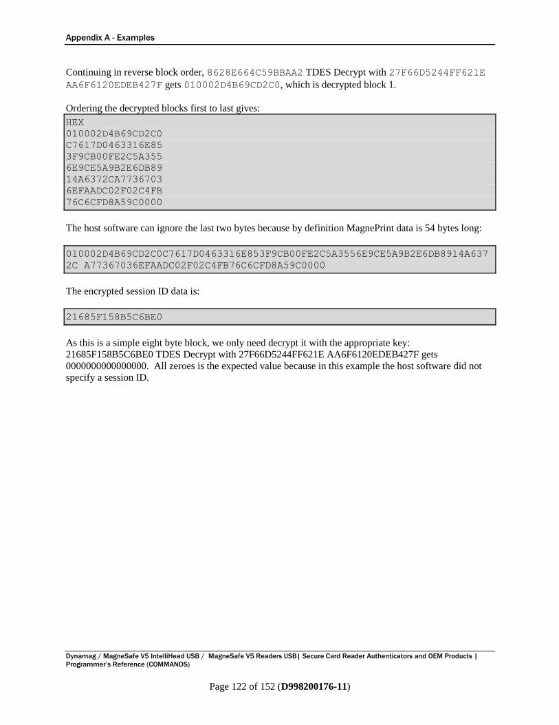
Appendix A - Examples
Dynamag / MagneSafe V5 IntelliHead USB / MagneSafe V5 Readers USB| Secure Card Reader Authenticators and OEM Products |
Programmer’s Reference (COMMANDS)
Page 122 of 152 (D998200176-11)
Continuing in reverse block order, 8628E664C59BBAA2 TDES Decrypt with 27F66D5244FF621E
AA6F6120EDEB427F gets 010002D4B69CD2C0, which is decrypted block 1.
Ordering the decrypted blocks first to last gives:
HEX
010002D4B69CD2C0
C7617D0463316E85
3F9CB00FE2C5A355
6E9CE5A9B2E6DB89
14A6372CA7736703
6EFAADC02F02C4FB
76C6CFD8A59C0000
The host software can ignore the last two bytes because by definition MagnePrint data is 54 bytes long:
010002D4B69CD2C0C7617D0463316E853F9CB00FE2C5A3556E9CE5A9B2E6DB8914A637
2C A77367036EFAADC02F02C4FB76C6CFD8A59C0000
The encrypted session ID data is:
21685F158B5C6BE0
As this is a simple eight byte block, we only need decrypt it with the appropriate key:
21685F158B5C6BE0 TDES Decrypt with 27F66D5244FF621E AA6F6120EDEB427F gets
0000000000000000. All zeroes is the expected value because in this example the host software did not
specify a session ID.
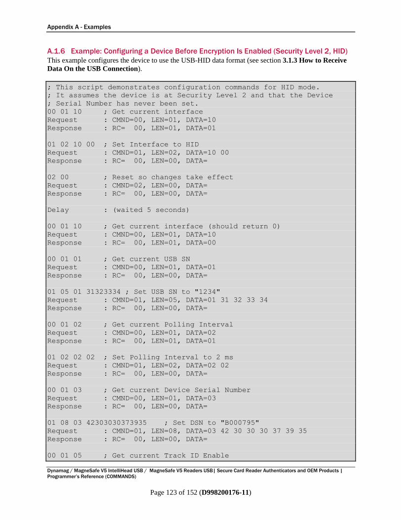
Appendix A - Examples
Dynamag / MagneSafe V5 IntelliHead USB / MagneSafe V5 Readers USB| Secure Card Reader Authenticators and OEM Products |
Programmer’s Reference (COMMANDS)
Page 123 of 152 (D998200176-11)
A.1.6 Example: Configuring a Device Before Encryption Is Enabled (Security Level 2, HID)
This example configures the device to use the USB-HID data format (see section 3.1.3 How to Receive
Data On the USB Connection).
; This script demonstrates configuration commands for HID mode.
; It assumes the device is at Security Level 2 and that the Device
; Serial Number has never been set.
00 01 10 ; Get current interface
Request : CMND=00, LEN=01, DATA=10
Response : RC= 00, LEN=01, DATA=01
01 02 10 00 ; Set Interface to HID
Request : CMND=01, LEN=02, DATA=10 00
Response : RC= 00, LEN=00, DATA=
02 00 ; Reset so changes take effect
Request : CMND=02, LEN=00, DATA=
Response : RC= 00, LEN=00, DATA=
Delay : (waited 5 seconds)
00 01 10 ; Get current interface (should return 0)
Request : CMND=00, LEN=01, DATA=10
Response : RC= 00, LEN=01, DATA=00
00 01 01 ; Get current USB SN
Request : CMND=00, LEN=01, DATA=01
Response : RC= 00, LEN=00, DATA=
01 05 01 31323334 ; Set USB SN to "1234"
Request : CMND=01, LEN=05, DATA=01 31 32 33 34
Response : RC= 00, LEN=00, DATA=
00 01 02 ; Get current Polling Interval
Request : CMND=00, LEN=01, DATA=02
Response : RC= 00, LEN=01, DATA=01
01 02 02 02 ; Set Polling Interval to 2 ms
Request : CMND=01, LEN=02, DATA=02 02
Response : RC= 00, LEN=00, DATA=
00 01 03 ; Get current Device Serial Number
Request : CMND=00, LEN=01, DATA=03
Response : RC= 00, LEN=00, DATA=
01 08 03 42303030373935 ; Set DSN to "B000795"
Request : CMND=01, LEN=08, DATA=03 42 30 30 30 37 39 35
Response : RC= 00, LEN=00, DATA=
00 01 05 ; Get current Track ID Enable
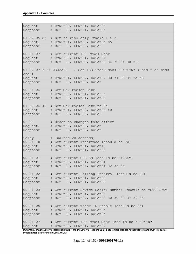
Appendix A - Examples
Dynamag / MagneSafe V5 IntelliHead USB / MagneSafe V5 Readers USB| Secure Card Reader Authenticators and OEM Products |
Programmer’s Reference (COMMANDS)
Page 124 of 152 (D998200176-11)
Request : CMND=00, LEN=01, DATA=05
Response : RC= 00, LEN=01, DATA=95
01 02 05 85 ; Set to read only Tracks 1 & 2
Request : CMND=01, LEN=02, DATA=05 85
Response : RC= 00, LEN=00, DATA=
00 01 07 ; Get current ISO Track Mask
Request : CMND=00, LEN=01, DATA=07
Response : RC= 00, LEN=06, DATA=30 34 30 34 30 59
01 07 07 303430342A4E ; Set ISO Track Mask "0404*N" (uses * as mask
char)
Request : CMND=01, LEN=07, DATA=07 30 34 30 34 2A 4E
Response : RC= 00, LEN=00, DATA=
00 01 0A ; Get Max Packet Size
Request : CMND=00, LEN=01, DATA=0A
Response : RC= 00, LEN=01, DATA=08
01 02 0A 40 ; Set Max Packet Size to 64
Request : CMND=01, LEN=02, DATA=0A 40
Response : RC= 00, LEN=00, DATA=
02 00 ; Reset so changes take effect
Request : CMND=02, LEN=00, DATA=
Response : RC= 00, LEN=00, DATA=
Delay : (waited 20 seconds)
00 01 10 ; Get current interface (should be 00)
Request : CMND=00, LEN=01, DATA=10
Response : RC= 00, LEN=01, DATA=00
00 01 01 ; Get current USB SN (should be "1234")
Request : CMND=00, LEN=01, DATA=01
Response : RC= 00, LEN=04, DATA=31 32 33 34
00 01 02 ; Get current Polling Interval (should be 02)
Request : CMND=00, LEN=01, DATA=02
Response : RC= 00, LEN=01, DATA=02
00 01 03 ; Get current Device Serial Number (should be "B000795")
Request : CMND=00, LEN=01, DATA=03
Response : RC= 00, LEN=07, DATA=42 30 30 30 37 39 35
00 01 05 ; Get current Track ID Enable (should be 85)
Request : CMND=00, LEN=01, DATA=05
Response : RC= 00, LEN=01, DATA=85
00 01 07 ; Get current ISO Track Mask (should be "0404*N")
Request : CMND=00, LEN=01, DATA=07

Appendix A - Examples
Dynamag / MagneSafe V5 IntelliHead USB / MagneSafe V5 Readers USB| Secure Card Reader Authenticators and OEM Products |
Programmer’s Reference (COMMANDS)
Page 125 of 152 (D998200176-11)
Response : RC= 00, LEN=06, DATA=30 34 30 34 2A 4E
00 01 0A ; Get Max Packet Size (should be 40)
Request : CMND=00, LEN=01, DATA=0A
Response : RC= 00, LEN=01, DATA=40
; ; END OF SCRIPT
Finished downloading
Card Encode Type = ISO
DUKPT Key Serial Number = 00000000000000000000
Track 1 Encrypted = 25 42 35 34 35 32 33 30 30 35 35 31 32 32 37 31 38
39 5E 48 4F 47 41 4E 2F 50 41 55 4C 20 20 20 20 20 20 5E 30 38 30 34
33 32 31 30 30 30 30 30 30 30 37 32 35 30 30 30 30 30 30 3F 00 00 00
00
Track 2 Encrypted = 3B 35 34 35 32 33 30 30 35 35 31 32 32 37 31 38 39
3D 30 38 30 34 33 32 31 30 30 30 30 30 30 30 37 32 35 30 3F 00 00 00
Track 3 Encrypted =
MagnePrint Status (hex) = 000005A1
MagnePrint Data (hex) = 01 00 02 8C 97 A8 CA 5B 69 CF D8 66 AA 23 88
E3 E1 2B E3 79 04 D3 31 6E F5 3F 9C 30 0B E2 43 A0 4E 6C 68 09 87 B2
52 DC 89 04 A6 F0 2B A7 73 E7 03 AF EA AD C0 1F 00 00
Device Serial Number = B000795
Track 1 Masked = %B5452300551227189^HOGAN/PAUL
^08043210000000725000000?
Track 2 Masked = ;5452300551227189=080432100000007250?
Encrypted Session ID (Hex) = 00 00 00 00 00 00 00 00
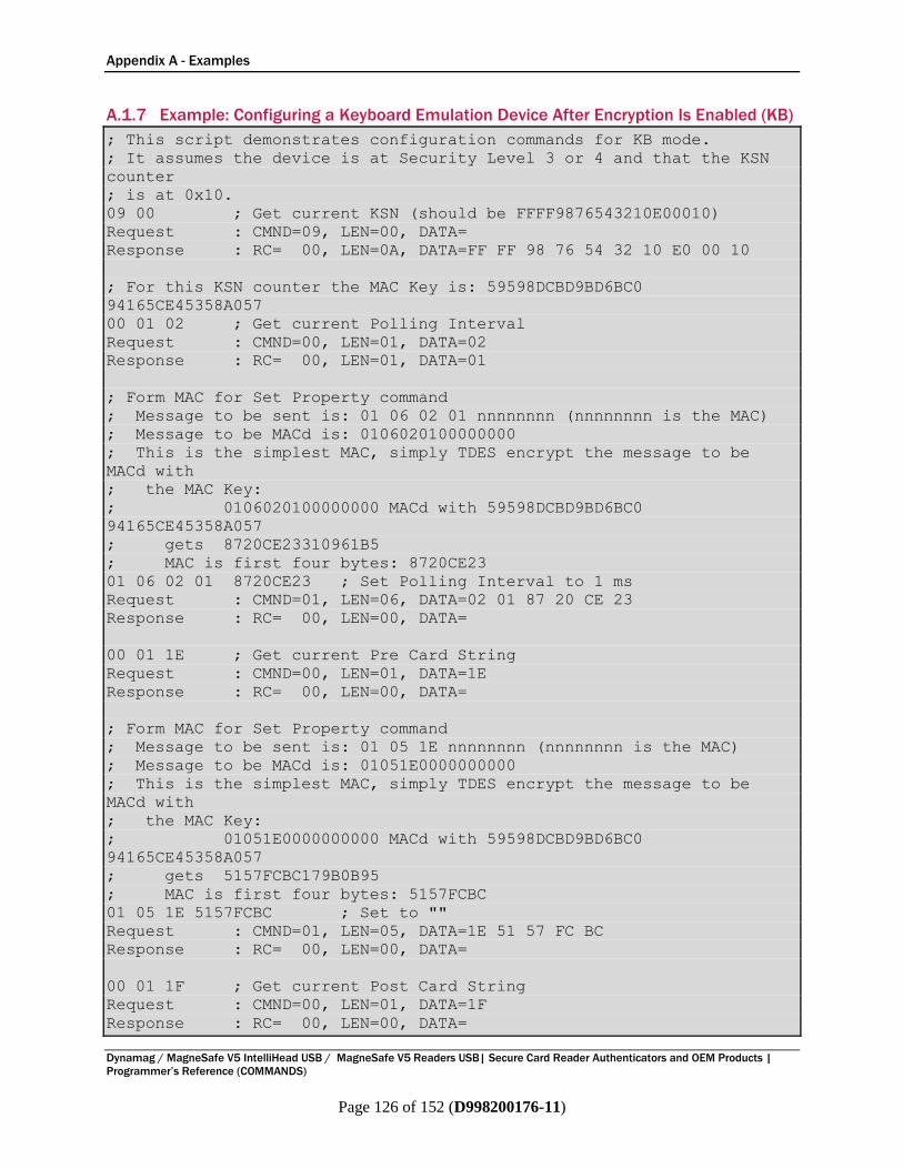
Appendix A - Examples
Dynamag / MagneSafe V5 IntelliHead USB / MagneSafe V5 Readers USB| Secure Card Reader Authenticators and OEM Products |
Programmer’s Reference (COMMANDS)
Page 126 of 152 (D998200176-11)
A.1.7 Example: Configuring a Keyboard Emulation Device After Encryption Is Enabled (KB)
; This script demonstrates configuration commands for KB mode.
; It assumes the device is at Security Level 3 or 4 and that the KSN
counter
; is at 0x10.
09 00 ; Get current KSN (should be FFFF9876543210E00010)
Request : CMND=09, LEN=00, DATA=
Response : RC= 00, LEN=0A, DATA=FF FF 98 76 54 32 10 E0 00 10
; For this KSN counter the MAC Key is: 59598DCBD9BD6BC0
94165CE45358A057
00 01 02 ; Get current Polling Interval
Request : CMND=00, LEN=01, DATA=02
Response : RC= 00, LEN=01, DATA=01
; Form MAC for Set Property command
; Message to be sent is: 01 06 02 01 nnnnnnnn (nnnnnnnn is the MAC)
; Message to be MACd is: 0106020100000000
; This is the simplest MAC, simply TDES encrypt the message to be
MACd with
; the MAC Key:
; 0106020100000000 MACd with 59598DCBD9BD6BC0
94165CE45358A057
; gets 8720CE23310961B5
; MAC is first four bytes: 8720CE23
01 06 02 01 8720CE23 ; Set Polling Interval to 1 ms
Request : CMND=01, LEN=06, DATA=02 01 87 20 CE 23
Response : RC= 00, LEN=00, DATA=
00 01 1E ; Get current Pre Card String
Request : CMND=00, LEN=01, DATA=1E
Response : RC= 00, LEN=00, DATA=
; Form MAC for Set Property command
; Message to be sent is: 01 05 1E nnnnnnnn (nnnnnnnn is the MAC)
; Message to be MACd is: 01051E0000000000
; This is the simplest MAC, simply TDES encrypt the message to be
MACd with
; the MAC Key:
; 01051E0000000000 MACd with 59598DCBD9BD6BC0
94165CE45358A057
; gets 5157FCBC179B0B95
; MAC is first four bytes: 5157FCBC
01 05 1E 5157FCBC ; Set to ""
Request : CMND=01, LEN=05, DATA=1E 51 57 FC BC
Response : RC= 00, LEN=00, DATA=
00 01 1F ; Get current Post Card String
Request : CMND=00, LEN=01, DATA=1F
Response : RC= 00, LEN=00, DATA=
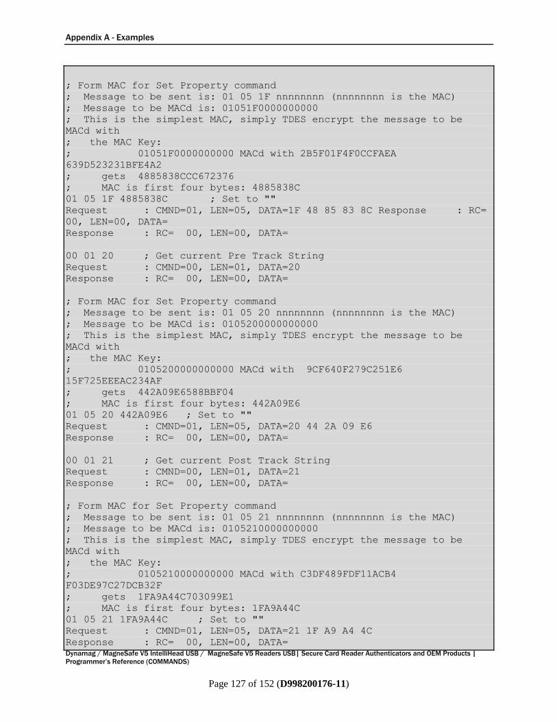
Appendix A - Examples
Dynamag / MagneSafe V5 IntelliHead USB / MagneSafe V5 Readers USB| Secure Card Reader Authenticators and OEM Products |
Programmer’s Reference (COMMANDS)
Page 127 of 152 (D998200176-11)
; Form MAC for Set Property command
; Message to be sent is: 01 05 1F nnnnnnnn (nnnnnnnn is the MAC)
; Message to be MACd is: 01051F0000000000
; This is the simplest MAC, simply TDES encrypt the message to be
MACd with
; the MAC Key:
; 01051F0000000000 MACd with 2B5F01F4F0CCFAEA
639D523231BFE4A2
; gets 4885838CCC672376
; MAC is first four bytes: 4885838C
01 05 1F 4885838C ; Set to ""
Request : CMND=01, LEN=05, DATA=1F 48 85 83 8C Response : RC=
00, LEN=00, DATA=
Response : RC= 00, LEN=00, DATA=
00 01 20 ; Get current Pre Track String
Request : CMND=00, LEN=01, DATA=20
Response : RC= 00, LEN=00, DATA=
; Form MAC for Set Property command
; Message to be sent is: 01 05 20 nnnnnnnn (nnnnnnnn is the MAC)
; Message to be MACd is: 0105200000000000
; This is the simplest MAC, simply TDES encrypt the message to be
MACd with
; the MAC Key:
; 0105200000000000 MACd with 9CF640F279C251E6
15F725EEEAC234AF
; gets 442A09E6588BBF04
; MAC is first four bytes: 442A09E6
01 05 20 442A09E6 ; Set to ""
Request : CMND=01, LEN=05, DATA=20 44 2A 09 E6
Response : RC= 00, LEN=00, DATA=
00 01 21 ; Get current Post Track String
Request : CMND=00, LEN=01, DATA=21
Response : RC= 00, LEN=00, DATA=
; Form MAC for Set Property command
; Message to be sent is: 01 05 21 nnnnnnnn (nnnnnnnn is the MAC)
; Message to be MACd is: 0105210000000000
; This is the simplest MAC, simply TDES encrypt the message to be
MACd with
; the MAC Key:
; 0105210000000000 MACd with C3DF489FDF11ACB4
F03DE97C27DCB32F
; gets 1FA9A44C703099E1
; MAC is first four bytes: 1FA9A44C
01 05 21 1FA9A44C ; Set to ""
Request : CMND=01, LEN=05, DATA=21 1F A9 A4 4C
Response : RC= 00, LEN=00, DATA=
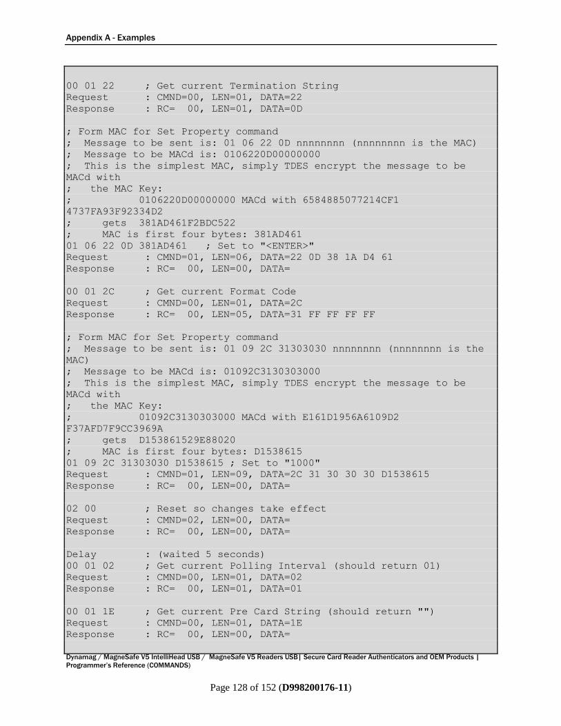
Appendix A - Examples
Dynamag / MagneSafe V5 IntelliHead USB / MagneSafe V5 Readers USB| Secure Card Reader Authenticators and OEM Products |
Programmer’s Reference (COMMANDS)
Page 128 of 152 (D998200176-11)
00 01 22 ; Get current Termination String
Request : CMND=00, LEN=01, DATA=22
Response : RC= 00, LEN=01, DATA=0D
; Form MAC for Set Property command
; Message to be sent is: 01 06 22 0D nnnnnnnn (nnnnnnnn is the MAC)
; Message to be MACd is: 0106220D00000000
; This is the simplest MAC, simply TDES encrypt the message to be
MACd with
; the MAC Key:
; 0106220D00000000 MACd with 6584885077214CF1
4737FA93F92334D2
; gets 381AD461F2BDC522
; MAC is first four bytes: 381AD461
01 06 22 0D 381AD461 ; Set to "<ENTER>"
Request : CMND=01, LEN=06, DATA=22 0D 38 1A D4 61
Response : RC= 00, LEN=00, DATA=
00 01 2C ; Get current Format Code
Request : CMND=00, LEN=01, DATA=2C
Response : RC= 00, LEN=05, DATA=31 FF FF FF FF
; Form MAC for Set Property command
; Message to be sent is: 01 09 2C 31303030 nnnnnnnn (nnnnnnnn is the
MAC)
; Message to be MACd is: 01092C3130303000
; This is the simplest MAC, simply TDES encrypt the message to be
MACd with
; the MAC Key:
; 01092C3130303000 MACd with E161D1956A6109D2
F37AFD7F9CC3969A
; gets D153861529E88020
; MAC is first four bytes: D1538615
01 09 2C 31303030 D1538615 ; Set to "1000"
Request : CMND=01, LEN=09, DATA=2C 31 30 30 30 D1538615
Response : RC= 00, LEN=00, DATA=
02 00 ; Reset so changes take effect
Request : CMND=02, LEN=00, DATA=
Response : RC= 00, LEN=00, DATA=
Delay : (waited 5 seconds)
00 01 02 ; Get current Polling Interval (should return 01)
Request : CMND=00, LEN=01, DATA=02
Response : RC= 00, LEN=01, DATA=01
00 01 1E ; Get current Pre Card String (should return "")
Request : CMND=00, LEN=01, DATA=1E
Response : RC= 00, LEN=00, DATA=
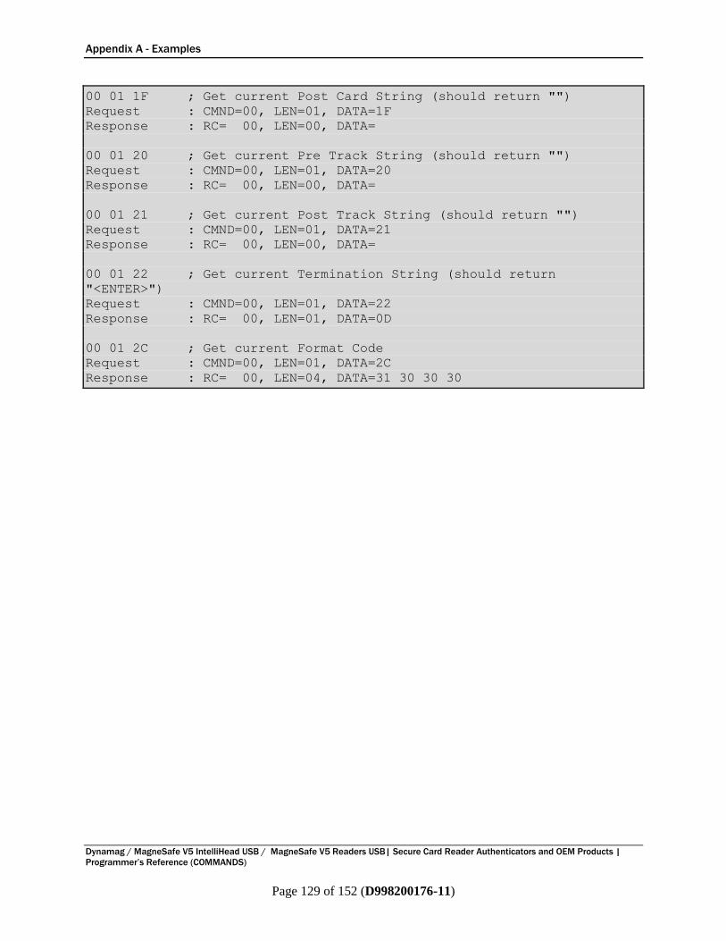
Appendix A - Examples
Dynamag / MagneSafe V5 IntelliHead USB / MagneSafe V5 Readers USB| Secure Card Reader Authenticators and OEM Products |
Programmer’s Reference (COMMANDS)
Page 129 of 152 (D998200176-11)
00 01 1F ; Get current Post Card String (should return "")
Request : CMND=00, LEN=01, DATA=1F
Response : RC= 00, LEN=00, DATA=
00 01 20 ; Get current Pre Track String (should return "")
Request : CMND=00, LEN=01, DATA=20
Response : RC= 00, LEN=00, DATA=
00 01 21 ; Get current Post Track String (should return "")
Request : CMND=00, LEN=01, DATA=21
Response : RC= 00, LEN=00, DATA=
00 01 22 ; Get current Termination String (should return
"<ENTER>")
Request : CMND=00, LEN=01, DATA=22
Response : RC= 00, LEN=01, DATA=0D
00 01 2C ; Get current Format Code
Request : CMND=00, LEN=01, DATA=2C
Response : RC= 00, LEN=04, DATA=31 30 30 30
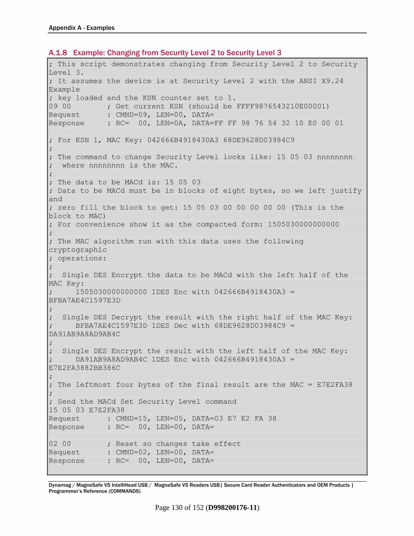
Appendix A - Examples
Dynamag / MagneSafe V5 IntelliHead USB / MagneSafe V5 Readers USB| Secure Card Reader Authenticators and OEM Products |
Programmer’s Reference (COMMANDS)
Page 130 of 152 (D998200176-11)
A.1.8 Example: Changing from Security Level 2 to Security Level 3
; This script demonstrates changing from Security Level 2 to Security
Level 3.
; It assumes the device is at Security Level 2 with the ANSI X9.24
Example
; key loaded and the KSN counter set to 1.
09 00 ; Get current KSN (should be FFFF9876543210E00001)
Request : CMND=09, LEN=00, DATA=
Response : RC= 00, LEN=0A, DATA=FF FF 98 76 54 32 10 E0 00 01
; For KSN 1, MAC Key: 042666B4918430A3 68DE9628D03984C9
;
; The command to change Security Level looks like: 15 05 03 nnnnnnnn
; where nnnnnnnn is the MAC.
;
; The data to be MACd is: 15 05 03
; Data to be MACd must be in blocks of eight bytes, so we left justify
and
; zero fill the block to get: 15 05 03 00 00 00 00 00 (This is the
block to MAC)
; For convenience show it as the compacted form: 1505030000000000
;
; The MAC algorithm run with this data uses the following
cryptographic
; operations:
;
; Single DES Encrypt the data to be MACd with the left half of the
MAC Key:
; 1505030000000000 1DES Enc with 042666B4918430A3 =
BFBA7AE4C1597E3D
;
; Single DES Decrypt the result with the right half of the MAC Key:
; BFBA7AE4C1597E3D 1DES Dec with 68DE9628D03984C9 =
DA91AB9A8AD9AB4C
;
; Single DES Encrypt the result with the left half of the MAC Key:
; DA91AB9A8AD9AB4C 1DES Enc with 042666B4918430A3 =
E7E2FA3882BB386C
;
; The leftmost four bytes of the final result are the MAC = E7E2FA38
;
; Send the MACd Set Security Level command
15 05 03 E7E2FA38
Request : CMND=15, LEN=05, DATA=03 E7 E2 FA 38
Response : RC= 00, LEN=00, DATA=
02 00 ; Reset so changes take effect
Request : CMND=02, LEN=00, DATA=
Response : RC= 00, LEN=00, DATA=

Appendix A - Examples
Dynamag / MagneSafe V5 IntelliHead USB / MagneSafe V5 Readers USB| Secure Card Reader Authenticators and OEM Products |
Programmer’s Reference (COMMANDS)
Page 131 of 152 (D998200176-11)
Delay : (waited 5 seconds)
09 00 ; Get current KSN (should be FFFF9876543210E00002)
Request : CMND=09, LEN=00, DATA=
Response : RC= 00, LEN=0A, DATA=FF FF 98 76 54 32 10 E0 00 02
15 00 ; Get current Security Level (Should be 03)
Request : CMND=15, LEN=00, DATA=
Response : RC= 00, LEN=01, DATA=03

Appendix A - Examples
Dynamag / MagneSafe V5 IntelliHead USB / MagneSafe V5 Readers USB| Secure Card Reader Authenticators and OEM Products |
Programmer’s Reference (COMMANDS)
Page 132 of 152 (D998200176-11)
A.1.9 Example: Changing from Security Level 2 to Security Level 4 (MSR Only)
; This script demonstrates changing from Security Level 2 to Security
Level 4.
; It assumes the device is at Security Level 2 with the ANSI X9.24
Example
; key loaded and the KSN counter set to 1.
09 00 ; Get current KSN (should be FFFF9876543210E00001)
Request : CMND=09, LEN=00, DATA=
Response : RC= 00, LEN=0A, DATA=FF FF 98 76 54 32 10 E0 00 01
; For KSN 1, MAC Key: 042666B4918430A3 68DE9628D03984C9
;
; The command to change Security Level looks like: 15 05 04 nnnnnnnn
; where nnnnnnnn is the MAC.
;
; The data to be MACd is: 15 05 04
; Data to be MACd must be in blocks of eight bytes, so we left justify
and
; zero fill the block to get: 15 05 04 00 00 00 00 00 (This is the
block to MAC)
; For convenience show it as the compacted form: 1505040000000000
;
; The MAC algorithm run with this data uses the following
cryptographic
; operations:
;
; Single DES Encrypt the data to be MACd with the left half of the
MAC Key:
; 1505040000000000 1DES Enc with 042666B4918430A3 =
644E76C88FFA0044
;
; Single DES Decrypt the result with the right half of the MAC Key:
; 644E76C88FFA0044 1DES Dec with 68DE9628D03984C9 =
DEAC363779906C06
;
; Single DES Encrypt the result with the left half of the MAC Key:
; DEAC363779906C06 1DES Enc with 042666B4918430A3 =
2F38A60E3F6AD6AD
;
; The leftmost four bytes of the final result are the MAC = 2F38A60E
;
; Send the MACd Set Security Level command
15 05 04 2F38A60E
Request : CMND=15, LEN=05, DATA=04 2F 38 A6 0E
Response : RC= 00, LEN=00, DATA=
02 00 ; Reset so changes take effect
Request : CMND=02, LEN=00, DATA=
Response : RC= 00, LEN=00, DATA=
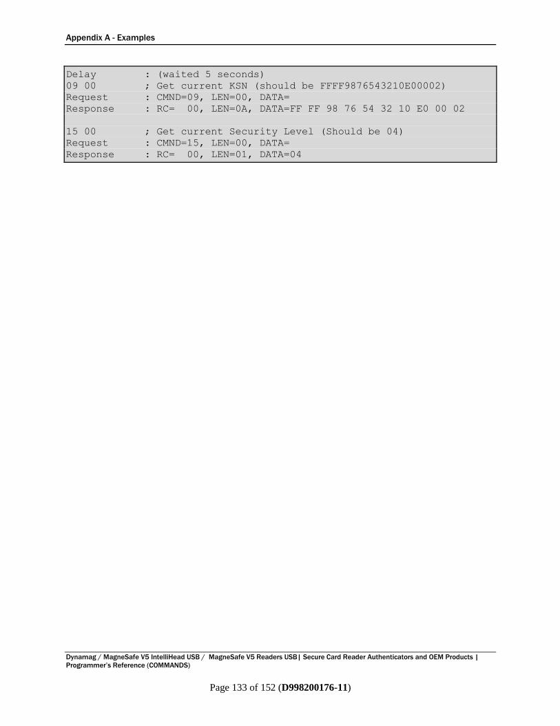
Appendix A - Examples
Dynamag / MagneSafe V5 IntelliHead USB / MagneSafe V5 Readers USB| Secure Card Reader Authenticators and OEM Products |
Programmer’s Reference (COMMANDS)
Page 133 of 152 (D998200176-11)
Delay : (waited 5 seconds)
09 00 ; Get current KSN (should be FFFF9876543210E00002)
Request : CMND=09, LEN=00, DATA=
Response : RC= 00, LEN=0A, DATA=FF FF 98 76 54 32 10 E0 00 02
15 00 ; Get current Security Level (Should be 04)
Request : CMND=15, LEN=00, DATA=
Response : RC= 00, LEN=01, DATA=04

Appendix A - Examples
Dynamag / MagneSafe V5 IntelliHead USB / MagneSafe V5 Readers USB| Secure Card Reader Authenticators and OEM Products |
Programmer’s Reference (COMMANDS)
Page 134 of 152 (D998200176-11)
A.1.10 Example: Changing from Security Level 3 to Security Level 4 (MSR Only)
; This script demonstrates changing from Security Level 3 to Security
Level 4.
; It assumes the device is at Security Level 3 with the ANSI X9.24
Example
; key loaded and the KSN counter set to 2.
09 00 ; Get current KSN (should be FFFF9876543210E00002)
Request : CMND=09, LEN=00, DATA=
Response : RC= 00, LEN=0A, DATA=FF FF 98 76 54 32 10 E0 00 02
; For KSN 2, MAC Key: C46551CEF9FDDBB0 AA9AD834130DC4C7
;
; The command to change Security Level looks like: 15 05 04 nnnnnnnn
; where nnnnnnnn is the MAC.
;
; The data to be MACd is: 15 05 04
; Data to be MACd must be in blocks of eight bytes, so we left justify
and
; zero fill the block to get: 15 05 04 00 00 00 00 00 (This is the
block to MAC)
; For convenience show it as the compacted form: 1505040000000000
;
; The MAC algorithm run with this data uses the following
cryptographic
; operations:
;
; Single DES Encrypt the data to be MACd with the left half of the
MAC Key:
; 1505040000000000 1DES Enc with C46551CEF9FDDBB0 =
735323A914B9482E
;
; Single DES Decrypt the result with the right half of the MAC Key:
; 735323A914B9482E 1DES Dec with AA9AD834130DC4C7 =
390E2E2AC8CB4EE6
;
; Single DES Encrypt the result with the left half of the MAC Key:
; 390E2E2AC8CB4EE6 1DES Enc with C46551CEF9FDDBB0 =
D9B7F3D8064C4B26
;
; The leftmost four bytes of the final result are the MAC = D9B7F3D8
;
; Send the MACd Set Security Level command
15 05 04 D9B7F3D8
Request : CMND=15, LEN=05, DATA=04 D9 B7 F3 D8
Response : RC= 00, LEN=00, DATA=
02 00 ; Reset so changes take effect
Request : CMND=02, LEN=00, DATA=
Response : RC= 00, LEN=00, DATA=

Appendix A - Examples
Dynamag / MagneSafe V5 IntelliHead USB / MagneSafe V5 Readers USB| Secure Card Reader Authenticators and OEM Products |
Programmer’s Reference (COMMANDS)
Page 135 of 152 (D998200176-11)
Delay : (waited 5 seconds)
09 00 ; Get current KSN (should be FFFF9876543210E00003)
Request : CMND=09, LEN=00, DATA=
Response : RC= 00, LEN=0A, DATA=FF FF 98 76 54 32 10 E0 00 03
15 00 ; Get current Security Level (Should be 04)
Request : CMND=15, LEN=00, DATA=
Response : RC= 00, LEN=01, DATA=04
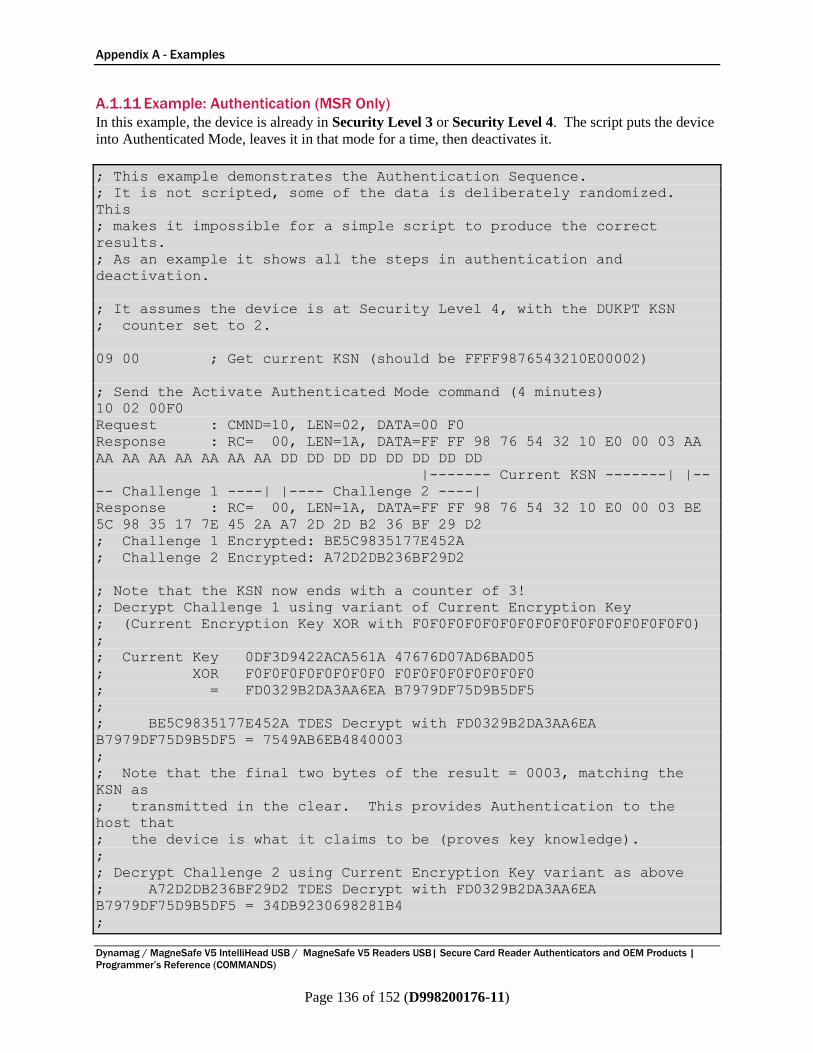
Appendix A - Examples
Dynamag / MagneSafe V5 IntelliHead USB / MagneSafe V5 Readers USB| Secure Card Reader Authenticators and OEM Products |
Programmer’s Reference (COMMANDS)
Page 136 of 152 (D998200176-11)
A.1.11 Example: Authentication (MSR Only)
In this example, the device is already in Security Level 3 or Security Level 4. The script puts the device
into Authenticated Mode, leaves it in that mode for a time, then deactivates it.
; This example demonstrates the Authentication Sequence.
; It is not scripted, some of the data is deliberately randomized.
This
; makes it impossible for a simple script to produce the correct
results.
; As an example it shows all the steps in authentication and
deactivation.
; It assumes the device is at Security Level 4, with the DUKPT KSN
; counter set to 2.
09 00 ; Get current KSN (should be FFFF9876543210E00002)
; Send the Activate Authenticated Mode command (4 minutes)
10 02 00F0
Request : CMND=10, LEN=02, DATA=00 F0
Response : RC= 00, LEN=1A, DATA=FF FF 98 76 54 32 10 E0 00 03 AA
AA AA AA AA AA AA AA DD DD DD DD DD DD DD DD
|------- Current KSN -------| |--
-- Challenge 1 ----| |---- Challenge 2 ----|
Response : RC= 00, LEN=1A, DATA=FF FF 98 76 54 32 10 E0 00 03 BE
5C 98 35 17 7E 45 2A A7 2D 2D B2 36 BF 29 D2
; Challenge 1 Encrypted: BE5C9835177E452A
; Challenge 2 Encrypted: A72D2DB236BF29D2
; Note that the KSN now ends with a counter of 3!
; Decrypt Challenge 1 using variant of Current Encryption Key
; (Current Encryption Key XOR with F0F0F0F0F0F0F0F0F0F0F0F0F0F0F0F0)
;
; Current Key 0DF3D9422ACA561A 47676D07AD6BAD05
; XOR F0F0F0F0F0F0F0F0 F0F0F0F0F0F0F0F0
; = FD0329B2DA3AA6EA B7979DF75D9B5DF5
;
; BE5C9835177E452A TDES Decrypt with FD0329B2DA3AA6EA
B7979DF75D9B5DF5 = 7549AB6EB4840003
;
; Note that the final two bytes of the result = 0003, matching the
KSN as
; transmitted in the clear. This provides Authentication to the
host that
; the device is what it claims to be (proves key knowledge).
;
; Decrypt Challenge 2 using Current Encryption Key variant as above
; A72D2DB236BF29D2 TDES Decrypt with FD0329B2DA3AA6EA
B7979DF75D9B5DF5 = 34DB9230698281B4
;
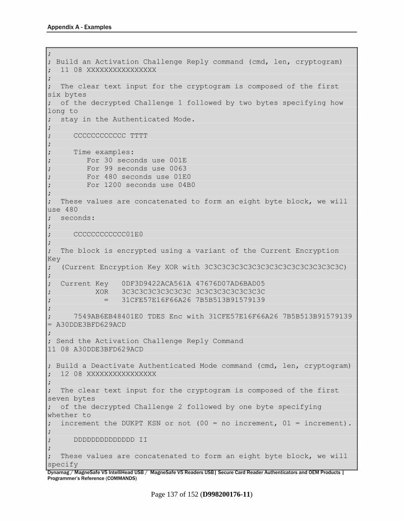
Appendix A - Examples
Dynamag / MagneSafe V5 IntelliHead USB / MagneSafe V5 Readers USB| Secure Card Reader Authenticators and OEM Products |
Programmer’s Reference (COMMANDS)
Page 137 of 152 (D998200176-11)
;
; Build an Activation Challenge Reply command (cmd, len, cryptogram)
; 11 08 XXXXXXXXXXXXXXXX
;
; The clear text input for the cryptogram is composed of the first
six bytes
; of the decrypted Challenge 1 followed by two bytes specifying how
long to
; stay in the Authenticated Mode.
;
; CCCCCCCCCCCC TTTT
;
; Time examples:
; For 30 seconds use 001E
; For 99 seconds use 0063
; For 480 seconds use 01E0
; For 1200 seconds use 04B0
;
; These values are concatenated to form an eight byte block, we will
use 480
; seconds:
;
; CCCCCCCCCCCC01E0
;
; The block is encrypted using a variant of the Current Encryption
Key
; (Current Encryption Key XOR with 3C3C3C3C3C3C3C3C3C3C3C3C3C3C3C3C)
;
; Current Key 0DF3D9422ACA561A 47676D07AD6BAD05
; XOR 3C3C3C3C3C3C3C3C 3C3C3C3C3C3C3C3C
; = 31CFE57E16F66A26 7B5B513B91579139
;
; 7549AB6EB48401E0 TDES Enc with 31CFE57E16F66A26 7B5B513B91579139
= A30DDE3BFD629ACD
;
; Send the Activation Challenge Reply Command
11 08 A30DDE3BFD629ACD
; Build a Deactivate Authenticated Mode command (cmd, len, cryptogram)
; 12 08 XXXXXXXXXXXXXXXX
;
; The clear text input for the cryptogram is composed of the first
seven bytes
; of the decrypted Challenge 2 followed by one byte specifying
whether to
; increment the DUKPT KSN or not (00 = no increment, 01 = increment).
;
; DDDDDDDDDDDDDD II
;
; These values are concatenated to form an eight byte block, we will
specify

Appendix A - Examples
Dynamag / MagneSafe V5 IntelliHead USB / MagneSafe V5 Readers USB| Secure Card Reader Authenticators and OEM Products |
Programmer’s Reference (COMMANDS)
Page 138 of 152 (D998200176-11)
; No Increment:
;
; DDDDDDDDDDDDDD00
;
; The block is encrypted using a variant of the Current Encryption
Key
; (Current Encryption Key XOR with 3C3C3C3C3C3C3C3C3C3C3C3C3C3C3C3C)
;
; Current Key 0DF3D9422ACA561A 47676D07AD6BAD05
; XOR 3C3C3C3C3C3C3C3C 3C3C3C3C3C3C3C3C
; = 31CFE57E16F66A26 7B5B513B91579139
;
; 34DB923069828100 TDES Enc with 31CFE57E16F66A26 7B5B513B91579139
= CA CB BD 5F 58 D5 C9 50
;
; Send the Deactivate Authenticated Mode command
12 08 CACBBD5F58D5C950

Appendix A - Examples
Dynamag / MagneSafe V5 IntelliHead USB / MagneSafe V5 Readers USB| Secure Card Reader Authenticators and OEM Products |
Programmer’s Reference (COMMANDS)
Page 139 of 152 (D998200176-11)
A.2 About the SDKs and Additional Examples MagTek provides SDKs and corresponding documentation for many programming languages and
operating systems that enable software developers to quickly develop custom host software that
communicates with this device, without having to deal with the complexities of platform APIs for direct
communication across the various available connection types, connecting using the various available
communication protocols, and parsing the various available data formats.
The SDKs and corresponding documentation include:
Functions for sending the direct commands described in this manual
Wrappers for commonly used commands and properties that further simplify development
Detailed compilable examples of processing incoming swipe data and using the direct commands and
properties described in this manual
To download the SDKs and documentation, search www.magtek.com for “SDK” and select the SDK and
documentation for the programming languages and platforms you need, or contact MagTek Support
Services for assistance.
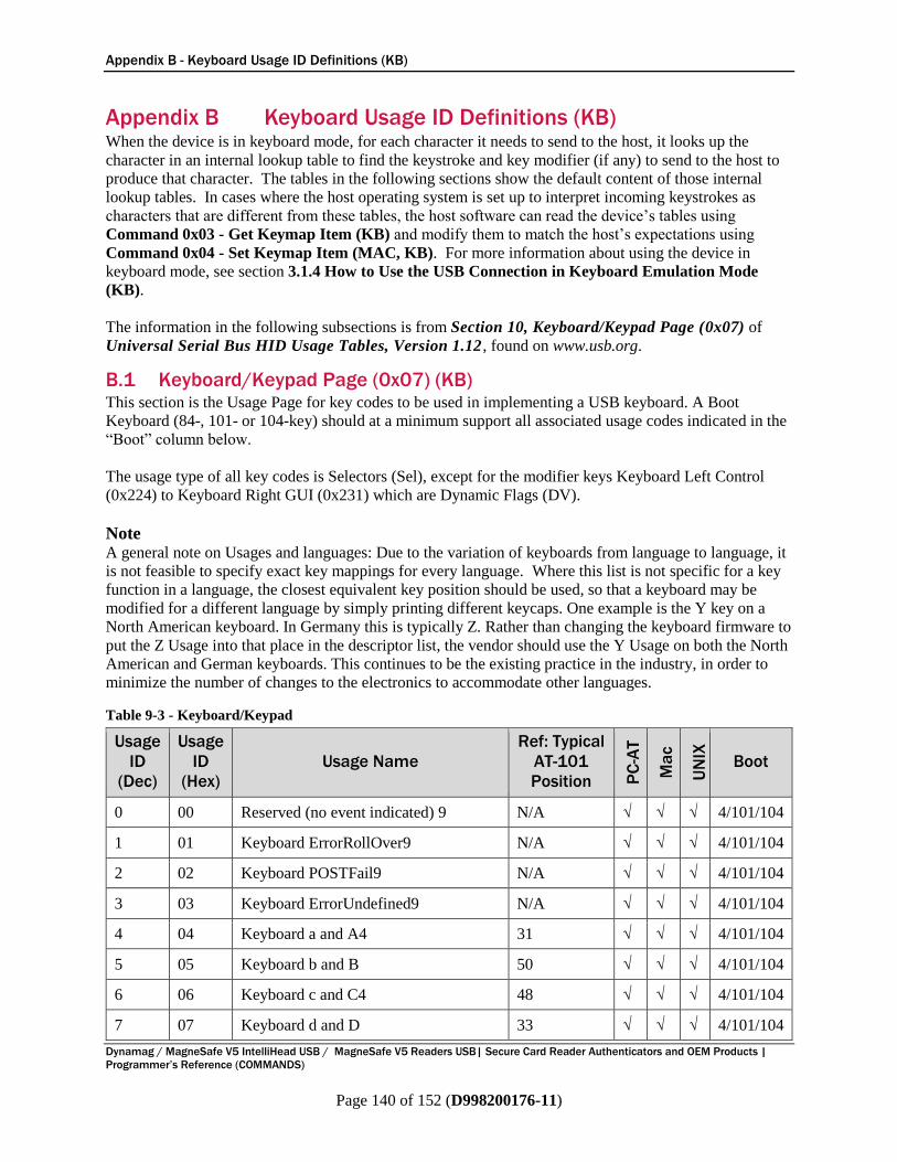
Appendix B - Keyboard Usage ID Definitions (KB)
Dynamag / MagneSafe V5 IntelliHead USB / MagneSafe V5 Readers USB| Secure Card Reader Authenticators and OEM Products |
Programmer’s Reference (COMMANDS)
Page 140 of 152 (D998200176-11)
Appendix B Keyboard Usage ID Definitions (KB) When the device is in keyboard mode, for each character it needs to send to the host, it looks up the
character in an internal lookup table to find the keystroke and key modifier (if any) to send to the host to
produce that character. The tables in the following sections show the default content of those internal
lookup tables. In cases where the host operating system is set up to interpret incoming keystrokes as
characters that are different from these tables, the host software can read the device’s tables using
Command 0x03 - Get Keymap Item (KB) and modify them to match the host’s expectations using
Command 0x04 - Set Keymap Item (MAC, KB). For more information about using the device in
keyboard mode, see section 3.1.4 How to Use the USB Connection in Keyboard Emulation Mode
(KB).
The information in the following subsections is from Section 10, Keyboard/Keypad Page (0x07) of
Universal Serial Bus HID Usage Tables, Version 1.12 , found on www.usb.org.
B.1 Keyboard/Keypad Page (0x07) (KB) This section is the Usage Page for key codes to be used in implementing a USB keyboard. A Boot
Keyboard (84-, 101- or 104-key) should at a minimum support all associated usage codes indicated in the
“Boot” column below.
The usage type of all key codes is Selectors (Sel), except for the modifier keys Keyboard Left Control
(0x224) to Keyboard Right GUI (0x231) which are Dynamic Flags (DV).
Note A general note on Usages and languages: Due to the variation of keyboards from language to language, it
is not feasible to specify exact key mappings for every language. Where this list is not specific for a key
function in a language, the closest equivalent key position should be used, so that a keyboard may be
modified for a different language by simply printing different keycaps. One example is the Y key on a
North American keyboard. In Germany this is typically Z. Rather than changing the keyboard firmware to
put the Z Usage into that place in the descriptor list, the vendor should use the Y Usage on both the North
American and German keyboards. This continues to be the existing practice in the industry, in order to
minimize the number of changes to the electronics to accommodate other languages.
Table 9-3 - Keyboard/Keypad
Usage
ID
(Dec)
Usage
ID
(Hex)
Usage Name
Ref: Typical
AT-101
Position PC
-AT
Ma
c
UN
IX
Boot
0 00 Reserved (no event indicated) 9 N/A √ √ √ 4/101/104
1 01 Keyboard ErrorRollOver9 N/A √ √ √ 4/101/104
2 02 Keyboard POSTFail9 N/A √ √ √ 4/101/104
3 03 Keyboard ErrorUndefined9 N/A √ √ √ 4/101/104
4 04 Keyboard a and A4 31 √ √ √ 4/101/104
5 05 Keyboard b and B 50 √ √ √ 4/101/104
6 06 Keyboard c and C4 48 √ √ √ 4/101/104
7 07 Keyboard d and D 33 √ √ √ 4/101/104
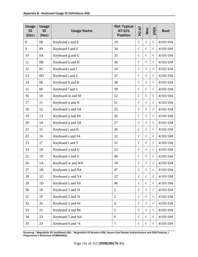
Appendix B - Keyboard Usage ID Definitions (KB)
Dynamag / MagneSafe V5 IntelliHead USB / MagneSafe V5 Readers USB| Secure Card Reader Authenticators and OEM Products |
Programmer’s Reference (COMMANDS)
Page 141 of 152 (D998200176-11)
Usage
ID
(Dec)
Usage
ID
(Hex)
Usage Name
Ref: Typical
AT-101
Position PC
-AT
Ma
c
UN
IX
Boot
8 08 Keyboard e and E 19 √ √ √ 4/101/104
9 09 Keyboard f and F 34 √ √ √ 4/101/104
10 0A Keyboard g and G 35 √ √ √ 4/101/104
11 0B Keyboard h and H 36 √ √ √ 4/101/104
12 0C Keyboard i and I 24 √ √ √ 4/101/104
13 0D Keyboard j and J 37 √ √ √ 4/101/104
14 0E Keyboard k and K 38 √ √ √ 4/101/104
15 0F Keyboard l and L 39 √ √ √ 4/101/104
16 10 Keyboard m and M 52 √ √ √ 4/101/104
17 11 Keyboard n and N 51 √ √ √ 4/101/104
18 12 Keyboard o and O4 25 √ √ √ 4/101/104
19 13 Keyboard p and P4 26 √ √ √ 4/101/104
20 14 Keyboard q and Q4 27 √ √ √ 4/101/104
21 15 Keyboard r and R 20 √ √ √ 4/101/104
22 16 Keyboard s and S4 32 √ √ √ 4/101/104
23 17 Keyboard t and T 21 √ √ √ 4/101/104
24 18 Keyboard u and U 23 √ √ √ 4/101/104
25 19 Keyboard v and V 49 √ √ √ 4/101/104
26 1A Keyboard w and W4 18 √ √ √ 4/101/104
27 1B Keyboard x and X4 47 √ √ √ 4/101/104
28 1C Keyboard y and Y4 22 √ √ √ 4/101/104
29 1D Keyboard z and Z4 46 √ √ √ 4/101/104
30 1E Keyboard 1 and !4 2 √ √ √ 4/101/104
31 1F Keyboard 2 and !4 3 √ √ √ 4/101/104
32 20 Keyboard 3 and #4 4 √ √ √ 4/101/104
33 21 Keyboard 4 and $4 5 √ √ √ 4/101/104
34 22 Keyboard 5 and %4 6 √ √ √ 4/101/104
35 23 Keyboard 6 and ^4 7 √ √ √ 4/101/104

Appendix B - Keyboard Usage ID Definitions (KB)
Dynamag / MagneSafe V5 IntelliHead USB / MagneSafe V5 Readers USB| Secure Card Reader Authenticators and OEM Products |
Programmer’s Reference (COMMANDS)
Page 142 of 152 (D998200176-11)
Usage
ID
(Dec)
Usage
ID
(Hex)
Usage Name
Ref: Typical
AT-101
Position PC
-AT
Ma
c
UN
IX
Boot
36 24 Keyboard 7 and &4 8 √ √ √ 4/101/104
37 25 Keyboard 8 and *4 9 √ √ √ 4/101/104
38 26 Keyboard 9 and (4 10 √ √ √ 4/101/104
39 27 Keyboard 0 and )4 11 √ √ √ 4/101/104
40 28 Keyboard Return (ENTER)5 43 √ √ √ 4/101/104
41 29 Keyboard ESCAPE 110 √ √ √ 4/101/104
42 2A Keyboard DELETE (Backspace) 15 √ √ √ 4/101/104
43 2B Keyboard Tab 16 √ √ √ 4/101/104
44 2C Keyboard Spacebar 61 √ √ √ 4/101/104
45 2D Keyboard - and (underscore)4 12 √ √ √ 4/101/104
46 2E Keyboard = and +4 13 √ √ √ 4/101/104
47 2F Keyboard [ and {4 27 √ √ √ 4/101/104
48 30 Keyboard ] and }4 28 √ √ √ 4/101/104
49 31 Keyboard \ and | 29 √ √ √ 4/101/104
50 32 Keyboard Non-US # and ~2 42 √ √ √ 4/101/104
51 33 Keyboard ; and :4 40 √ √ √ 4/101/104
52 34 Keyboard ‘ and “4 41 √ √ √ 4/101/104
53 35 Keyboard Grave Accent and Tilde4 1 √ √ √ 4/101/104
54 36 Keyboard, and <4 53 √ √ √ 4/101/104
55 37 Keyboard. and >4 54 √ √ √ 4/101/104
56 38 Keyboard / and ? 55 √ √ √ 4/101/104
57 39 Keyboard Caps Lock11 30 √ √ √ 4/101/104
58 3A Keyboard F1 112 √ √ √ 4/101/104
59 3B Keyboard F2 113 √ √ √ 4/101/104
60 3C Keyboard F3 114 √ √ √ 4/101/104
61 3D Keyboard F4 115 √ √ √ 4/101/104
62 3E Keyboard F5 116 √ √ √ 4/101/104
63 3F Keyboard F6 117 √ √ √ 4/101/104
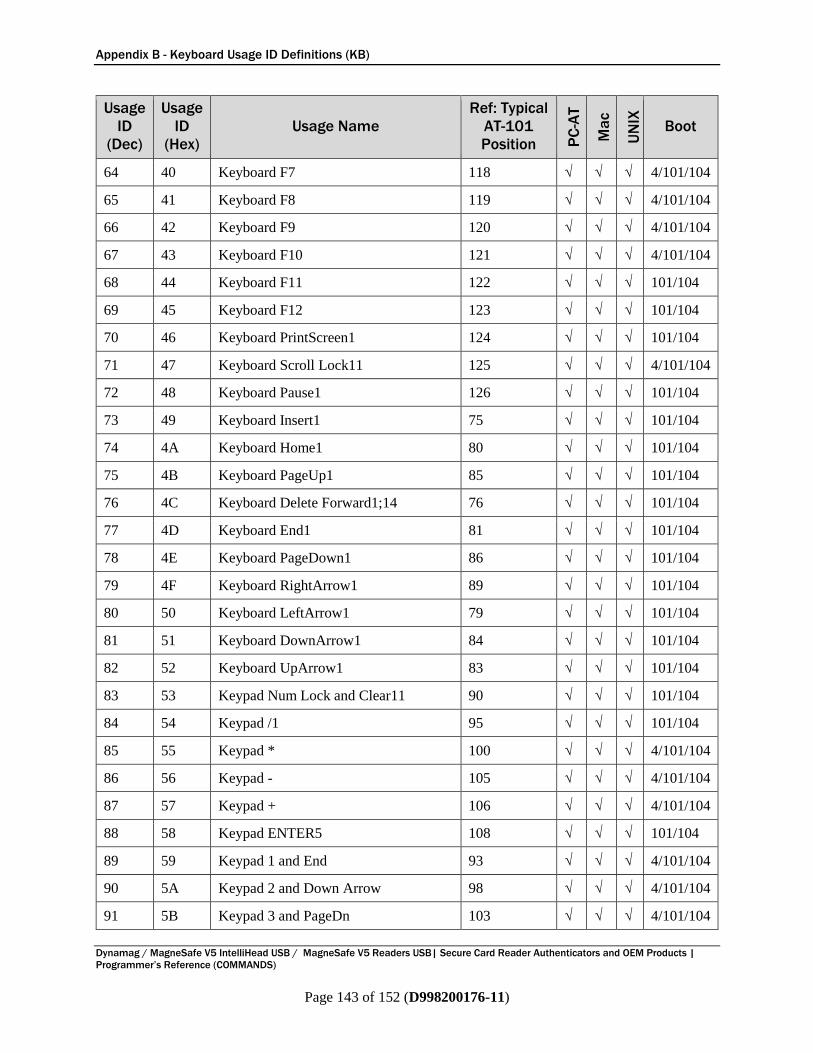
Appendix B - Keyboard Usage ID Definitions (KB)
Dynamag / MagneSafe V5 IntelliHead USB / MagneSafe V5 Readers USB| Secure Card Reader Authenticators and OEM Products |
Programmer’s Reference (COMMANDS)
Page 143 of 152 (D998200176-11)
Usage
ID
(Dec)
Usage
ID
(Hex)
Usage Name
Ref: Typical
AT-101
Position PC
-AT
Ma
c
UN
IX
Boot
64 40 Keyboard F7 118 √ √ √ 4/101/104
65 41 Keyboard F8 119 √ √ √ 4/101/104
66 42 Keyboard F9 120 √ √ √ 4/101/104
67 43 Keyboard F10 121 √ √ √ 4/101/104
68 44 Keyboard F11 122 √ √ √ 101/104
69 45 Keyboard F12 123 √ √ √ 101/104
70 46 Keyboard PrintScreen1 124 √ √ √ 101/104
71 47 Keyboard Scroll Lock11 125 √ √ √ 4/101/104
72 48 Keyboard Pause1 126 √ √ √ 101/104
73 49 Keyboard Insert1 75 √ √ √ 101/104
74 4A Keyboard Home1 80 √ √ √ 101/104
75 4B Keyboard PageUp1 85 √ √ √ 101/104
76 4C Keyboard Delete Forward1;14 76 √ √ √ 101/104
77 4D Keyboard End1 81 √ √ √ 101/104
78 4E Keyboard PageDown1 86 √ √ √ 101/104
79 4F Keyboard RightArrow1 89 √ √ √ 101/104
80 50 Keyboard LeftArrow1 79 √ √ √ 101/104
81 51 Keyboard DownArrow1 84 √ √ √ 101/104
82 52 Keyboard UpArrow1 83 √ √ √ 101/104
83 53 Keypad Num Lock and Clear11 90 √ √ √ 101/104
84 54 Keypad /1 95 √ √ √ 101/104
85 55 Keypad * 100 √ √ √ 4/101/104
86 56 Keypad - 105 √ √ √ 4/101/104
87 57 Keypad + 106 √ √ √ 4/101/104
88 58 Keypad ENTER5 108 √ √ √ 101/104
89 59 Keypad 1 and End 93 √ √ √ 4/101/104
90 5A Keypad 2 and Down Arrow 98 √ √ √ 4/101/104
91 5B Keypad 3 and PageDn 103 √ √ √ 4/101/104

Appendix B - Keyboard Usage ID Definitions (KB)
Dynamag / MagneSafe V5 IntelliHead USB / MagneSafe V5 Readers USB| Secure Card Reader Authenticators and OEM Products |
Programmer’s Reference (COMMANDS)
Page 144 of 152 (D998200176-11)
Usage
ID
(Dec)
Usage
ID
(Hex)
Usage Name
Ref: Typical
AT-101
Position PC
-AT
Ma
c
UN
IX
Boot
92 5C Keypad 4 and Left Arrow 92 √ √ √ 4/101/104
93 5D Keypad 4 and Left Arrow 97 √ √ √ 4/101/104
94 5E Keypad 4 and Left Arrow 102 √ √ √ 4/101/104
95 5F Keypad 7 and Home 91 √ √ √ 4/101/104
96 60 Keypad 8 and Up Arrow 96 √ √ √ 4/101/104
97 61 Keypad 9 and PageUp 101 √ √ √ 4/101/104
98 62 Keypad 0 and Insert 99 √ √ √ 4/101/104
99 63 Keypad . and Delete 104 √ √ √ 4/101/104
100 64 Keyboard Non-US \ and |3;6 45 √ √ √ 4/101/104
101 65 Keyboard Application10 129 √ √ 104
102 66 Keyboard Power9 = √ √
103 67 Keypad = √
104 68 Keyboard F13 62 √
105 69 Keyboard F14 63 √
106 6A Keyboard F15 64 √
107 6B Keyboard F16 65
107 6C Keyboard F17
109 6D Keyboard F18
110 6E Keyboard F19
111 6F Keyboard F20
112 70 Keyboard F21
113 71 Keyboard F22
114 72 Keyboard F23
115 73 Keyboard F24
116 74 Keyboard Execute √
117 75 Keyboard Help √
118 76 Keyboard Menu √
119 77 Keyboard Select √
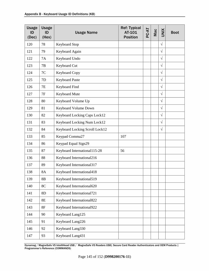
Appendix B - Keyboard Usage ID Definitions (KB)
Dynamag / MagneSafe V5 IntelliHead USB / MagneSafe V5 Readers USB| Secure Card Reader Authenticators and OEM Products |
Programmer’s Reference (COMMANDS)
Page 145 of 152 (D998200176-11)
Usage
ID
(Dec)
Usage
ID
(Hex)
Usage Name
Ref: Typical
AT-101
Position PC
-AT
Ma
c
UN
IX
Boot
120 78 Keyboard Stop √
121 79 Keyboard Again √
122 7A Keyboard Undo √
123 7B Keyboard Cut √
124 7C Keyboard Copy √
125 7D Keyboard Paste √
126 7E Keyboard Find √
127 7F Keyboard Mute √
128 80 Keyboard Volume Up √
129 81 Keyboard Volume Down √
130 82 Keyboard Locking Caps Lock12 √
131 83 Keyboard Locking Num Lock12 √
132 84 Keyboard Locking Scroll Lock12 √
133 85 Keypad Comma27 107
134 86 Keypad Equal Sign29
135 87 Keyboard International115-28 56
136 88 Keyboard International216
137 89 Keyboard International317
138 8A Keyboard International418
139 8B Keyboard International519
140 8C Keyboard International620
141 8D Keyboard International721
142 8E Keyboard International822
143 8F Keyboard International922
144 90 Keyboard Lang125
145 91 Keyboard Lang226
146 92 Keyboard Lang330
147 93 Keyboard Lang431
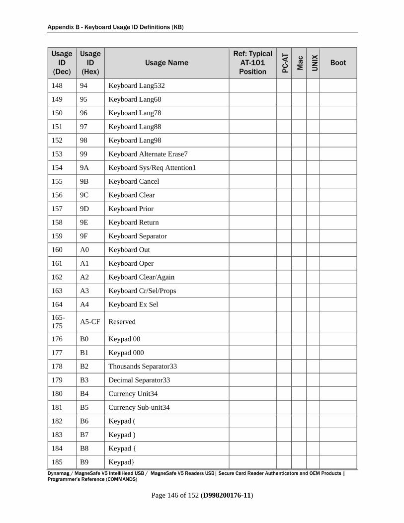
Appendix B - Keyboard Usage ID Definitions (KB)
Dynamag / MagneSafe V5 IntelliHead USB / MagneSafe V5 Readers USB| Secure Card Reader Authenticators and OEM Products |
Programmer’s Reference (COMMANDS)
Page 146 of 152 (D998200176-11)
Usage
ID
(Dec)
Usage
ID
(Hex)
Usage Name
Ref: Typical
AT-101
Position PC
-AT
Ma
c
UN
IX
Boot
148 94 Keyboard Lang532
149 95 Keyboard Lang68
150 96 Keyboard Lang78
151 97 Keyboard Lang88
152 98 Keyboard Lang98
153 99 Keyboard Alternate Erase7
154 9A Keyboard Sys/Req Attention1
155 9B Keyboard Cancel
156 9C Keyboard Clear
157 9D Keyboard Prior
158 9E Keyboard Return
159 9F Keyboard Separator
160 A0 Keyboard Out
161 A1 Keyboard Oper
162 A2 Keyboard Clear/Again
163 A3 Keyboard Cr/Sel/Props
164 A4 Keyboard Ex Sel
165-
175 A5-CF Reserved
176 B0 Keypad 00
177 B1 Keypad 000
178 B2 Thousands Separator33
179 B3 Decimal Separator33
180 B4 Currency Unit34
181 B5 Currency Sub-unit34
182 B6 Keypad (
183 B7 Keypad )
184 B8 Keypad {
185 B9 Keypad}

Appendix B - Keyboard Usage ID Definitions (KB)
Dynamag / MagneSafe V5 IntelliHead USB / MagneSafe V5 Readers USB| Secure Card Reader Authenticators and OEM Products |
Programmer’s Reference (COMMANDS)
Page 147 of 152 (D998200176-11)
Usage
ID
(Dec)
Usage
ID
(Hex)
Usage Name
Ref: Typical
AT-101
Position PC
-AT
Ma
c
UN
IX
Boot
186 BA Keypad Tab
187 BB Keypad Backspace
188 BC Keypad A
189 BD Keypad B
190 BE Keypad C
191 BF Keypad D
192 C0 Keypad E
193 C1 Keypad F
194 C2 Keypad XOR
195 C3 Keypad ^
196 C4 Keypad %
197 C5 Keypad <
198 C6 Keypad >
199 C7 Keypad &
200 C8 Keypad &&
201 C9 Keypad |
202 CA Keypad ||
203 CB Keypad :
204 CC Keypad #
205 CD Keypad Space
206 CE Keypad @
207 CF Keypad !
208 D0 Keypad Memory Store
209 D1 Keypad Memory Recall
210 D2 Keypad Memory Clear
211 D3 Keypad Memory Add
212 D4 Keypad Memory Subtract
213 D5 Keypad Memory Multiple
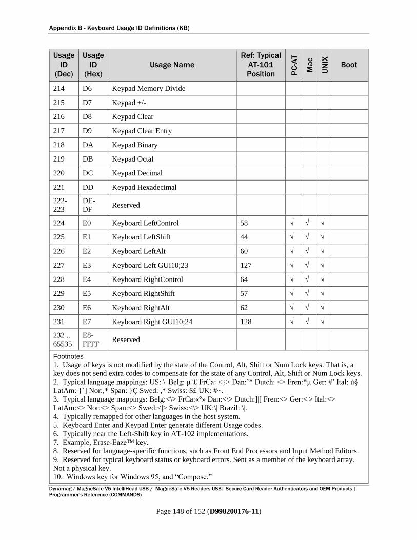
Appendix B - Keyboard Usage ID Definitions (KB)
Dynamag / MagneSafe V5 IntelliHead USB / MagneSafe V5 Readers USB| Secure Card Reader Authenticators and OEM Products |
Programmer’s Reference (COMMANDS)
Page 148 of 152 (D998200176-11)
Usage
ID
(Dec)
Usage
ID
(Hex)
Usage Name
Ref: Typical
AT-101
Position PC
-AT
Ma
c
UN
IX
Boot
214 D6 Keypad Memory Divide
215 D7 Keypad +/-
216 D8 Keypad Clear
217 D9 Keypad Clear Entry
218 DA Keypad Binary
219 DB Keypad Octal
220 DC Keypad Decimal
221 DD Keypad Hexadecimal
222-
223
DE-
DF Reserved
224 E0 Keyboard LeftControl 58 √ √ √
225 E1 Keyboard LeftShift 44 √ √ √
226 E2 Keyboard LeftAlt 60 √ √ √
227 E3 Keyboard Left GUI10;23 127 √ √ √
228 E4 Keyboard RightControl 64 √ √ √
229 E5 Keyboard RightShift 57 √ √ √
230 E6 Keyboard RightAlt 62 √ √ √
231 E7 Keyboard Right GUI10;24 128 √ √ √
232 ..
65535
E8-
FFFF Reserved
Footnotes
1. Usage of keys is not modified by the state of the Control, Alt, Shift or Num Lock keys. That is, a
key does not send extra codes to compensate for the state of any Control, Alt, Shift or Num Lock keys.
2. Typical language mappings: US: \| Belg: µ`£ FrCa: <}> Dan:’* Dutch: <> Fren:*µ Ger: #’ Ital: ù§
LatAm: }`] Nor:,* Span: }Ç Swed: ,* Swiss: $£ UK: #~.
3. Typical language mappings: Belg:<\> FrCa:«°» Dan:<\> Dutch:]|[ Fren:<> Ger:<|> Ital:<>
LatAm:<> Nor:<> Span:<> Swed:<|> Swiss:<\> UK:\| Brazil: \|.
4. Typically remapped for other languages in the host system.
5. Keyboard Enter and Keypad Enter generate different Usage codes.
6. Typically near the Left-Shift key in AT-102 implementations.
7. Example, Erase-Eaze™ key.
8. Reserved for language-specific functions, such as Front End Processors and Input Method Editors.
9. Reserved for typical keyboard status or keyboard errors. Sent as a member of the keyboard array.
Not a physical key.
10. Windows key for Windows 95, and “Compose.”

Appendix B - Keyboard Usage ID Definitions (KB)
Dynamag / MagneSafe V5 IntelliHead USB / MagneSafe V5 Readers USB| Secure Card Reader Authenticators and OEM Products |
Programmer’s Reference (COMMANDS)
Page 149 of 152 (D998200176-11)
Usage
ID
(Dec)
Usage
ID
(Hex)
Usage Name
Ref: Typical
AT-101
Position PC
-AT
Ma
c
UN
IX
Boot
11. Implemented as a non-locking key; sent as member of an array.
12. Implemented as a locking key; sent as a toggle button. Available for legacy support; however,
most systems should use the non-locking version of this key.
13. Backs up the cursor one position, deleting a character as it goes.
14. Deletes one character without changing position.
15-20. See additional foot notes in Universal Serial Bus HID Usage Tables, Copyright © 1996-2005,
USB Implementers Forum.
21. Toggle Double-Byte/Single-Byte mode.
22. Undefined, available for other Front End Language Processors.
23. Windowing environment key, examples are Microsoft Left Win key, Mac Left Apple key, Sun
Left Meta key
24. Windowing environment key, examples are Microsoft® RIGHT WIN key, Macintosh® RIGHT
APPLE key, Sun® RIGHT META key.
25. Hangul/English toggle key. This usage is used as an input method editor control key on a Korean
language keyboard.
26. Hanja conversion key. This usage is used as an input method editor control key on a Korean
language keyboard.
27. Keypad Comma is the appropriate usage for the Brazilian keypad period (.) key. This represents
the closest possible match, and system software should do the correct mapping based on the current
locale setting.
28. Keyboard International1 should be identified via footnote as the appropriate usage for the
Brazilian forward-slash (/) and question-mark (?) key. This usage should also be renamed to either
“Keyboard Non-US / and ?” or to “Keyboard International1” now that it's become clear that it does not
only apply to Kanji keyboards anymore.
29. Used on AS/400 keyboards.
30. Defines the Katakana key for Japanese USB word-processing keyboards.
31. Defines the Hiragana key for Japanese USB word-processing keyboards.
32. Usage 0x94 (Keyboard LANG5) “Defines the Zenkaku/Hankaku key for Japanese USB word-
processing keyboards.
33. The symbol displayed will depend on the current locale settings of the operating system. For
example, the US thousands separator would be a comma, and the decimal separator would be a period.
34. The symbol displayed will depend on the current locale settings of the operating system. For
example the US currency unit would be $ and the sub-unit would be ¢.

Appendix B - Keyboard Usage ID Definitions (KB)
Dynamag / MagneSafe V5 IntelliHead USB / MagneSafe V5 Readers USB| Secure Card Reader Authenticators and OEM Products |
Programmer’s Reference (COMMANDS)
Page 150 of 152 (D998200176-11)
B.2 Modifier Byte Definitions (KB) This appendix is from Section 8.3 Report Format for Array Items of Device Class Definition for
Human Interface Devices (HID) Version 1.11, found on www.usb.org. The modifier byte is defined
in Table 9-4.
Table 9-4 - Modifier Byte
Bit Key
0 LEFT CTRL
1 LEFT SHIFT
2 LEFT ALT
3 LEFT GUI
4 RIGHT CTRL
5 RIGHT SHIFT
6 RIGHT ALT
7 RIGHT GUI

Appendix C - Identifying ISO/ABA and AAMVA Cards (MSR Only)
Dynamag / MagneSafe V5 IntelliHead USB / MagneSafe V5 Readers USB| Secure Card Reader Authenticators and OEM Products |
Programmer’s Reference (COMMANDS)
Page 151 of 152 (D998200176-11)
Appendix C Identifying ISO/ABA and AAMVA Cards (MSR Only)
C.1 ISO/ABA Financial Cards The device uses the rules below to determine if a card is an ISO/ABA card (per ISO 7811-2,2001),
which affects incoming Card Encode Type (HID, TLV, GATT) and the masking used for Masked
Track Data. ISO defines a particular and different format for the data on each of the three tracks of the
card. The format of the card depends on decisions made by the entity that issued the card. For example,
some organizations may choose to use the Track 1 encoding format for Track 2 data, or other
permutations that do not conform to the standard. Many MagTek devices will decode these cards and
identify the card format “Other.” The device will only consider ISO Financial masking for cards it
classifies as ISO, which it determines according to the following rules:
1) If the low level decoding algorithm determines the data for every track conforms to the ISO format
defined for that track, the card is classified as ISO.
2) The device determines masking behavior for each track independently. One track may qualify for
masking and another may not.
3) Track 1:
a) The device’s intent is to send the card’s Format Code in the clear, the PAN partially masked, the
Name and Expiration Date in the clear, and the rest of the track masked.
b) If the card’s Format Code, PAN, Name, or Expiration Date are not correctly structured, the
device will transmit the rest of the track, starting with the point of discrepancy, in the clear. The
device defines “correct structure” for track 1 as follows:
i) If the card’s Format Code, PAN, Name, or Expiration Date contain the ‘?’ character (End
Sentinel), the field is not correctly structured.
ii) A correctly structured Format Code is the first character on the track and is the character ‘B’.
iii) A correctly structured PAN has a maximum of 19 digits and is ended by the character ‘^’
(Field Separator).
iv) A correctly structured Name has a maximum of 26 characters and is ended by the character
‘^’ (Field Separator).
v) A correctly structured Expiration Date has 4 characters.
4) Tracks 2 & 3:
a) The device’s intent is to send the PAN partially masked, the Expiration Date in the clear, and the
rest of the track masked.
b) If the PAN or Expiration Date are not correctly structured, the device will send the rest of the
track, starting at the point of discrepancy, in the clear. The device defines “correct structure” for
track 2 and track 3 as follows:
i) If the PAN or Expiration Date contain the ‘?’ character (End Sentinel), the field is not
correctly structured.
ii) A correctly structured PAN has a maximum of 19 digits and is ended by the character ‘=’
(Field Separator).
iii) A correctly structured Expiration Date has 4 characters.
Appendix C - Identifying ISO/ABA and AAMVA Cards (MSR Only)
Dynamag / MagneSafe V5 IntelliHead USB / MagneSafe V5 Readers USB| Secure Card Reader Authenticators and OEM Products |
Programmer’s Reference (COMMANDS)
Page 152 of 152 (D998200176-11)
C.2 AAMVA Driver Licenses The device uses the following rules to determine if a card is an AAMVA card:
1) If the device reads three tracks of data and Track 1 is formatted per ISO Track 1 rules, Track 2 is
formatted per ISO Track 2 rules, and Track 3 is formatted per ISO Track 1 [sic.] rules, the card is
considered to be an AAMVA card. Some MagTek devices do not support reading of Track 3, so this
rule will not apply on such devices.
2) If a low level decoding algorithm finds data for the available tracks to be in the ISO format particular
to each track, and Track 2 contains a correctly structured PAN field whose first 6 digits are “604425”
or contain values in the range “636000” to “636062” inclusive, the card is considered to be an
AAMVA card.
AAMVA card masking, when enabled, works as follows:
1) The device sends track 1 and track 3 entirely masked; all character positions are filled with zeroes.
2) Track 2 is treated as follows:
a) The device’s intent is to send the Driver License ID (DLID) partially masked, the Expiration Date
in the clear, the Birth Date in the clear, and the rest of the track masked.
b) If the DLID, Expiration Date, or Birth Date are not correctly structured, the rest of the track,
starting at the point of discrepancy, will be sent in the clear. The device defines “correctly
structured” as follows:
i) If the DLID, Expiration Date, or Birth Date contain the ‘?’ character (End Sentinel), the field
is not correctly structured.
ii) A correctly structured DLID has a maximum of 19 digits and is terminated by the character
‘=’ (Field Separator).
iii) A correctly structured Expiration Date has 4 characters.
iv) A correctly structured Birth Date has 8 characters.


