
AB1280AB12130
ABNRC
technology
4URD A : B L LEA T :I DGI ED S : I GC NI
MAN Y D
ProDigital RoHScompliant
www.sterling-power.comwww.sterling-power.usa.com
Alternator-to-Battery Chargersand Remote Control
STERLINGPOWER PRODUCTS
e1
12 v 80 - 130 amp24 v 80 amp
Safety Instructions
General Precautions
Precautions against Gas Explosions
Precautions when Handling Batteries
Important: If your alternator has got its own battery voltage sense wire, then this has to be removed from the battery terminal and should be connected to the alternator’s own B+ output instead. This will prevent contradictory regulation between the alternator and the alternator-to-battery charger.
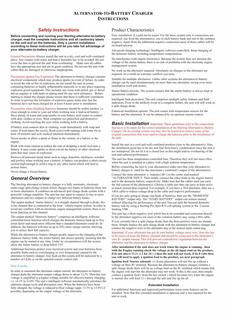
Product CharacteristicsEasy installation: It could not be easier. For the basic system only 4 connections are Before connecting and running your Sterling alternator-to-battery required: one from the alternator(s), one to each battery bank and one to the common charger, read the complete instructions and all cautionary labels negative. Apart from the additional negative connection most of these cables will be on the unit and on the batteries. Only a correct installation on board anyway.according to these instructions will let you take full advantage of
your alternator-to-battery charger. Advanced charging technology: Intelligent, software-controlled, 4step charging of the domestic battery including temperature compensation.
Always install the unit in a dry, cool and well-ventilated No interference with engine electronics: Because the system does not increase the place. Any contact with water and heavy humidity has to be avoided. Do not voltage of the starter battery there is no risk of problems with the electronic engine cover the fans to prevent the unit from overheating. Make sure all cables management system.have the appropriate size and are in good condition. Do not run the unit with
cables that are damaged or otherwise inappropriate. No work on the alternator required: Absolutely no changes to the alternator are required. As a result no warranty conflicts can arise.
The alternator-to-battery charger contains Suitable for multiple alternators: Unlike other systems the alternator-to-battery electrical components which may produce sparks in event of failure. In order charger can be used simultaneously on more than one alternator, saving even more to avoid the risk of fire or explosion, do not install the unit in rooms installation work and money.containing batteries or highly inflammable materials or in any place requiring
explosion-proof equipment. This includes any room with petrol, gas or diesel Starter battery priority: The system ensures that the starter battery is always kept in driven engines or with tanks or piping used for any such substance. Before operational condition.starting to install the charger please ensure that there is sufficient ventilation.
Intelligent fault protection: The unit comprises multiple safety features and fault In order to prevent the formation of explosive gases make sure that the indicators. Even in the unlikely event of a complete failure, the unit will still work as batteries have not been charged for at least 4 hours prior to installation.a split charge diode.
Someone should be within earshot, i.e. Enhanced installation options: The unit comes with temperature sensors for the close enough to come to your aid when working near a lead-acid battery. battery and the alternator. It can be enhanced by an optional remote control.Have plenty of water and soap nearby in case battery acid comes in contact
with skin, clothes or eyes. Wear complete eye protection and protective clothing. Avoid touching the eyes while working with a battery. Basic Installation If battery acid contacts skin or clothing, wash immediately with soap and water. If acid enters the eye(s), flood eye(s) with running cold water for at least 10 minutes and seek medical attention immediately.
Never smoke or allow a spark or flame in the vicinity of a battery or the engine.
Install the unit in a cool and well-ventilated position close to the alternator(s). Also, Work with extra caution to reduce the risk of dropping a metal tool onto a the installation point has to be dry and free from heavy condensation since the unit is battery. It may create sparks or short-circuit the battery or other electrical not waterproof. Do not fit it in a closed box as this might lead to overheating of the parts that may cause an explosion.unit and reduced performance.
Remove all personal metal items such as rings, bracelets, necklaces, watches The unit has three temperature-controlled fans. Therefore they will run more often and jewlery when working near a battery. A battery can produce a short-circuit when the unit is installed in a place with a high ambient temperature.current high enough to weld a ring or any other metal which will lead to Before connecting the unit to your alternator(s) make sure that your alternator-to-serious burns.battery charger is rated for the maximum ( combined ) output of the alternator(s).Never charge a frozen battery.Connect the main alternator/ s output(s) (B+) to the center stud marked “ALTERNATOR INPUT. Then simply connect the other studs to the engine battery General Overviewand to the domestic battery, respectively. Make sure that the cables used can carry
The Sterling alternator-to-battery charger is a fully automatic, electronic the full current of the alternator(s). Choose a cable size that can carry at least twice multi-stage split-charge system which charges two banks of batteries from one as much current than required. For example, if you have a 70A alternator, then use a or more alternators. It combines an advanced split charge diode system with a 140A cable to reduce voltage drop in the cable and improve performancepowerful voltage amplifier. The unit has one input to connect to one or more If you are only going to charge one bank of batteries, then use the “DOMESTIC alternators and two outputs to charge two different battery banks. BATTERY” output only. The “START BATTERY” output can remain unused The output marked “starter battery” is a straight channel through a diode; this without affecting the performance of the unit.You can split the boosted domestic is the channel that is connected to the boat / vehicle engine system. In order to battery side by using a Sterling Pro Split R 0 volt spliting system or the Current avoid any conflicts with an electronic engine management system, there is no limiting VSR. boost function on this channel. The unit has a short negative wire which has to be extended and connected directly The output marked “domestic battery” comprises an intelligent, software- to the alternator negative (or case) or the common battery neg using a 60A cable.controlled boost function which charges the domestic battery bank up to five If you currently have a split charge diode, then the three positive wires are already times faster and much more efficient than a standard alternator could do. In there. Simply replace the split charge diode with the alternator-to-battery charger and addition, the batteries will take in up to 50% more charge current, allowing connect the negative wire to the alternator neg or the nearest main comm neg.you to utilize their full capacity.
While the alternator-to-battery charger greatly improves the charging of the domestic battery bank, the starter battery has always priority, ensuring that the engine can be started at any time. Under no circumstances will the system allow the starter battery to drop below 13V.
After installation if the unit does not work when the engine is running , then Additional functions protect your electrical system and your batteries from with the Engine running check the voltage at the alt input stud on the product, possible faults such as overcharging or over temperature caused by the if its not above 13.3 ( x 2 for 24 v ) then the unit will not work, if its 0 volts then alternator to battery charger. Any fault on the system will be indicated by a you will need to apply a ignition feed to the product, see next paragraphnumber of LEDs or on the optional remote control unit.
Ignition feed/ Starter solenoid: Some alternators will not fire up without a voltage on their B+ terminal. Because the alternator-to-battery charger contains a split charge diode there will be no voltage feed on the B+ terminal which means that
In order to maximist the alternator output current, the alternator-to-battery the engine will start but the alternator may not work. If this is the case, then simply charger pulls the alternator output voltage down to about 13,3V. Then this low connect a ignition feed ( from the key switch ) which becomes live when the engine voltage is amplified to a higher voltage suitable for effective battery charging, is started. this will feed 12 v through the unit and fire up the alti.e. 14.1V to 14.8V. The unit’s intelligent software automatically calculates the optimum charge cycle and absorption time. When the batteries have been Extended Installationfully charged, the voltage is reduced to float voltage (appr. 13.5V to 13.8V) if
For additional functions and improved performance some extra features can be possible, depending on the output voltage of the alternator.
installed. Note that this extended installation is optional and is not required for the unit to work.
How it works
Important: These guidelines refer to the connections that have to be made for the correct installation of the Sterling Alternator-to-Battery Charger. On an existing system you may also be required to remove some of the original connections that were used to charge the batteries prior to the installation of the unit.
(4)
ALTERNATOR-TO-BATTERY CHARGER
INSTRUCTIONS
Battery Temperature: Using its ring terminal end, connect one of the enclosed temperature sensors to your domestic battery’s negative post.
Connect the two small wires on the other end to the small terminals marked “battery temp”. Be careful not to damage or alter the temperature sensor in any way! The system will then sense the battery temperature and change the output voltage in accordance with the recommended temperature compensation for the selected battery type.
Important: All voltages indicated in these instructions refer to an ambient temperature of 20°C. When using a battery temperature sensor these voltages will be different due to temperature compensation.
Alternator Temperature: Using its ring terminal end, connect one of the enclosed temperature sensors to your alternator case or negative stud.
Connect the two small wires on the other end to the small terminals marked “alt temp”. Be careful not to damage or alter the temperature sensor in any way! The system will then sense the alternator temperature and will disengage the voltage amplifier if the alternator temperature exceeds 100°C.
Voltage Sensing: The alternator-to-battery charger in its standard configuration senses all voltages directly at the unit. However, in order to compensate a possible voltage drop between the unit and your domestic battery, you can run a simple 0.5mm² wire from the positive stud of your domestic battery to the terminal marked “dom sense”.
Multiple Alternators: The alternator-to-battery charger can be used on more than one alternator at the same time. Simply connect all alternator outputs (B+) to the alternator input terminal on the unit. Make sure that your alternator-to-battery charger is rated for the combined maximum output of the alternators.
Remote Control: The remote control kit is an optional extra
The remote control will keep you informed about voltages, currents, temperatures and other operating figures. In the event of a problem, it indicates what the problem is.
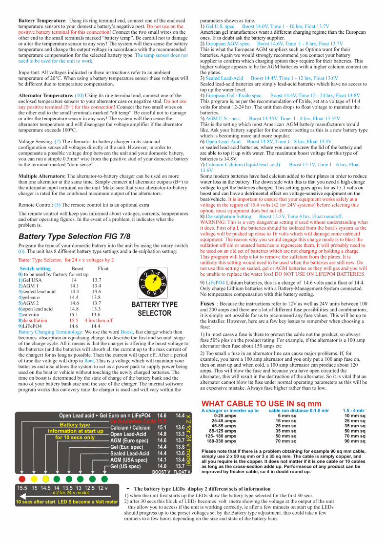
Battery Type Selection FIG 7/8Program the type of your domestic battery into the unit by using the rotary switch
. The unit has 8 different battery type settings and a de-sulphation setting:
Boost Float to be used by factory for set upGel USA 14 13.7AGM 1 14.1 13.4sealed lead acid 14.4 13.6gel euro 14.4 13.8AGM 2 14.6 13.7open lead acid 14.8 13.3calcuim 15.1 13.6
LiFePO4 14.6 14.4
.
Do not use on the positive battery terminal for this connection!
Do not use any positive terminal (B+) for this connection!
Batter Type Selector, for 24 v x voltages by 2
de sulfation 15.5 4 hrs then off
Boost 14.0V, Time 1 - 10 hrs, Float 13.7V
Boost 14.6V, Time 1 - 8 hrs, Float 13.7V
The temp sensor does not need to be used for the unit to work,
Boost 14.4V, Time 12 - 24 hrs, Float 13.8V
Boost 14.8V, Time 1 - 8 hrs, Float 13.3V
Boost 15.1V, Time 1 - 6 hrs, Float 13.6V
Boost 15.5V, Time 4 hrs, Float none/off.
Switch setting 0)1)2)3)4)5)6)7)8)9)
(10)
(7)
(5)
(6)
Gel U.S. spec.
European AGM spec.
Sealed Lead-Acid Boost 14.4V, Time 1 - 12 hrs, Float 13.6V
European Gel / Exide spec.
AGM U.S. spec. Boost 14.35V, Time 1 - 8 hrs, Float 13.35V
Open Lead-Acid
Calcium-Calcium (liquid lead-acid):
De-sulphation Setting:
LiFePO4
Battery Charging Terminology: Boost
float
It is important to ensure that your equipment works safely at a voltage in the region of 15.4 volts (x2 for 24V systems) before selecting this option, most equipment does but not all.
WARNING: This is a very dangerous setting if used without understanding what it does. First of all, the batteries should be isolated from the boat’s system as the voltage will be pushed up close to 16 volts which will damage some onboard equipment. The reason why you would engage this charge mode is to blast the sulfation off old or unused batteries to regenerate them. It will probably need to be used on an old set of batteries which are not charging or holding a charge. This program will help a lot to remove the sulfation from the plates. It is unlikely this setting would need to be used when the batteries are still new. Do not use this setting on sealed, gel or AGM batteries as they will gas and you will be unable to replace the water loss! DO NOT USE ON LIFEPO4 BATTERIES
parameters shown as time.
This is what the European AGM suppliers such as Optima want for their batteries. Again we would strongly recommend you contact your battery supplier to confirm which charging option they require for their batteries. This higher voltage appears to be for AGM batteries with a higher calcium content on the plates.
Sealed lead-acid batteries are simply lead-acid batteries which have no access to top up the water level.
This program is, as per the recommendation of Exide, set at a voltage of 14.4 volts for about 12-24 hrs. The unit then drops to float voltage to maintain the batteries.
This is the setting which most American AGM battery manufacturers would like. Ask your battery supplier for the correct setting as this is a new battery type which is becoming more and more popular.
9) Lithium batteries, this is a charge of 14.6 volts and a float of 14.4. Only charge Lithium batteries with a Battery-Management-System connected.No temperature compensation with this battery setting.
Fuses : Because the instructions refer to 12V as well as 24V units between 100 and 200 amps and there are a lot of different fuse possibilities and combinations, it is simply not possible for us to recommend any fuse values. This will be up to the installer. However, here are a few key issues to remember when choosing a fuse:
We use the word , fast charge which then 1) In most cases a fuse is there to protect the cable not the product, so always becomes absorption or equalising charge, to describe the first and second stage fuse 50% plus on the product rating. For example, if the alternator is a 100 amp of the charge cycle. All it means is that the charger is offering the boost voltage to alternator then fuse about 150 amps etc the batteries (and the batteries will absorb all the current up to the max current of
2) Too small a fuse in an alternator line can cause major problems. If, for the charger) for as long as possible. Then the current will taper off. After a period example, you have a 100 amp alternator and you only put a 100 amp fuse on, of time the voltage will drop to . This is a voltage which will maintain your then on start up and when cold, a 100 amp alternator can produce about 120 batteries and also allows the system to act as a power pack to supply power being amps. This will blow the fuse and because you have open circuited the used on the boat or vehicle without touching the newly charged batteries. The alternator, this will result in the destruction of the alternator. So it is vital that an time on boost is determined by the state of charge of the battery bank and the alternator cannot blow its fuse under normal operating parameters as this will be ratio of your battery bank size and the size of the charger. The internal software an expensive mistake. Always fuse higher rather than to lowprogram works this out every time the charger is used and will vary within the
1) American gel manufactures want a different charging regime than the European ones. If in doubt ask the battery supplier.2)
3)
4)
5)
6) or sealed lead-acid batteries, where you can unscrew the lid of the battery and are able to top it up with water. The maximum boost voltage for this type of batteries is 14.8V.7)
Some modern batteries have had calcium added to their plates in order to reduce water loss in the battery. The down side with this is that you need a high charge voltage to get the batteries charged. This setting goes up as far as 15.1 volts on boost and can have a detrimental effect on voltage-senstive equipment on the boat/vehicle.
8)
WHAT CABLE TO USE IN sq mmA charger or inverter up to cable run distance 0-1.5 mtr 1.5 - 4 mtr 0-25 amps 6 mm sq 10 mm sq 25-45 amps 16 mm sq 25 mm sq 45-85 amps 25 mm sq 35 mm sq 85-125 amps 35 mm sq 50 mm sq 125- 180 amps 50 mm sq 70 mm sq 180-330 amps 70 mm sq 90 mm sq
Please note that if there is a problem obtaining for example 90 sq mm cable, simply use 2 x 50 sq mm or 3 x 35 sq mm. The cable is simply copper, and all you require is the copper. It does not matter if it is one cable or 10 cables as long as the cross-section adds up. Performance of any product can be improved by thicker cable, so if in doubt round up.
Battery type information at start up
for 10 secs only
15.5 15 14.5 14 13.5 13 12.5 12 v
10 secs after start LED S become a Volt meter
15.1 13.6 14.8 13.3 14.6 13.7 14.4 13.8 14.4 13.6 14.1 13.4 14.0 13.7BOOST V FLOAT V
Calcium / Calcium Open Lead-Acid AGM (Euro spec) Gel (Eur. spec) Sealed Lead-Acid AGM (USA spec) Gel (US spec)
De-Sulphation Cycle 15.5Open Lead acid + Gel Euro on = LiFePO4 14.6 14.4
x 2 for 24 v model
x 2 fo
r 24 v m
odel
6 7
5
8
4
9
3
2
0
1
BATTERY TYPESELECTOR
- The battery type LEDs display 2 different sets of information
1) when the unit first starts up the LEDs show the battery type selected for the first 30 secs.2) after 30 secs this block of LEDs becomes volt metre showing the voltage at the output of the unit this allow you to access if the unit is working correctly, ie after a few minuets on start up the LEDsshould progress up to the preset voltages set by the Battery type adjustment. this could take a few minuets to a few hours depending on the size and state of the battery bank
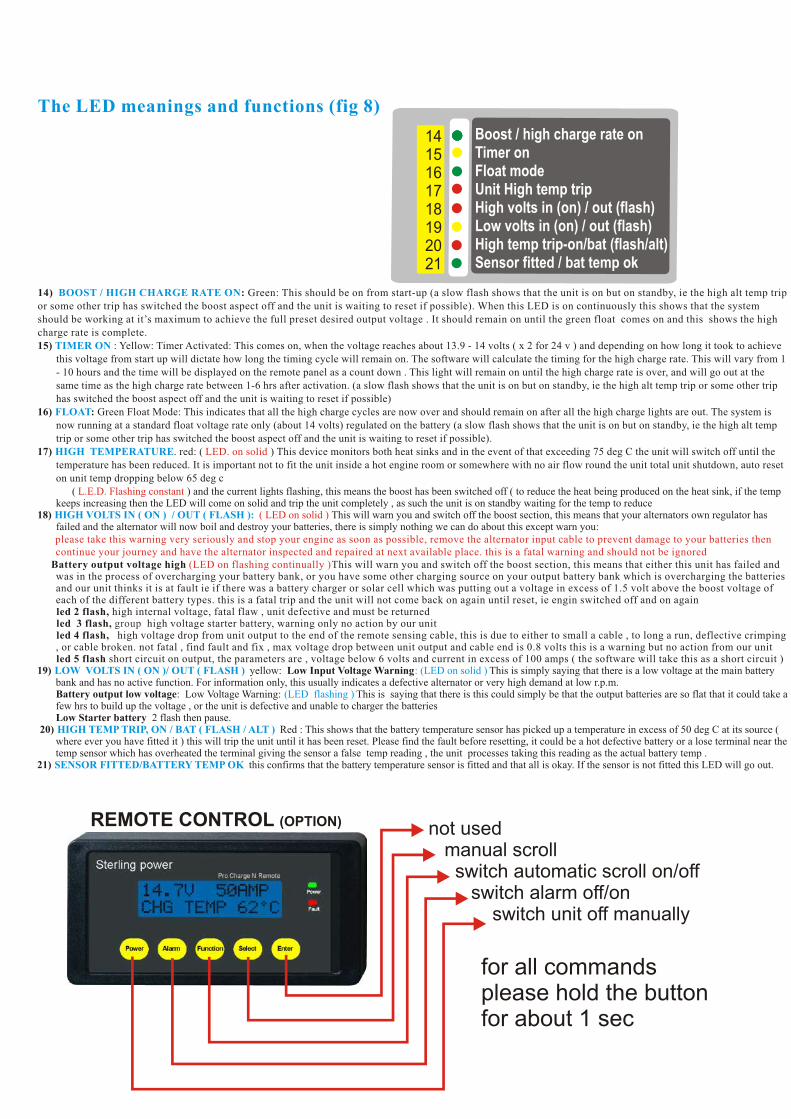
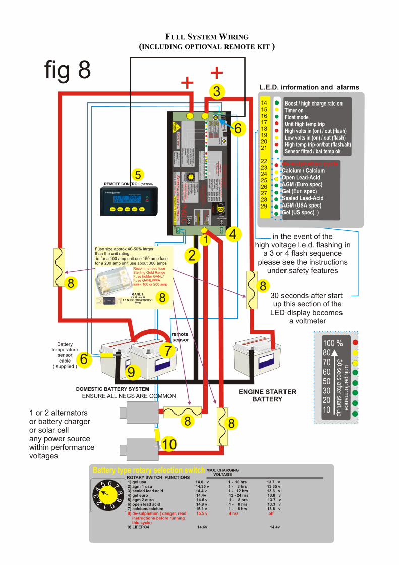
The LED meanings and functions (fig 8)
BOOST / HIGH CHARGE RATE ON
TIMER ON
FLOAT
HIGH TEMPERATURE
HIGH VOLTS IN ( ON ) / OUT ( FLASH ):
LOW VOLTS IN ( ON )/ OUT ( FLASH ) : (LED on solid )
(LED flashing )
HIGH TEMP TRIP, ON / BAT ( FLASH / ALT )
SENSOR FITTED/BATTERY TEMP OK
14) : Green: This should be on from start-up (a slow flash shows that the unit is on but on standby, ie the high alt temp trip or some other trip has switched the boost aspect off and the unit is waiting to reset if possible). When this LED is on continuously this shows that the system should be working at it’s maximum to achieve the full preset desired output voltage . It should remain on until the green float comes on and this shows the high charge rate is complete.15) : Yellow: Timer Activated: This comes on, when the voltage reaches about 13.9 - 14 volts ( x 2 for 24 v ) and depending on how long it took to achieve
this voltage from start up will dictate how long the timing cycle will remain on. The software will calculate the timing for the high charge rate. This will vary from 1 - 10 hours and the time will be displayed on the remote panel as a count down . This light will remain on until the high charge rate is over, and will go out at the same time as the high charge rate between 1-6 hrs after activation. (a slow flash shows that the unit is on but on standby, ie the high alt temp trip or some other trip has switched the boost aspect off and the unit is waiting to reset if possible)
16) : Green Float Mode: This indicates that all the high charge cycles are now over and should remain on after all the high charge lights are out. The system is now running at a standard float voltage rate only (about 14 volts) regulated on the battery (a slow flash shows that the unit is on but on standby, ie the high alt temp trip or some other trip has switched the boost aspect off and the unit is waiting to reset if possible).
17) . red: ( ) This device monitors both heat sinks and in the event of that exceeding 75 deg C the unit will switch off until the temperature has been reduced. It is important not to fit the unit inside a hot engine room or somewhere with no air flow round the unit total unit shutdown, auto reset on unit temp dropping below 65 deg c
( ) and the current lights flashing, this means the boost has been switched off ( to reduce the heat being produced on the heat sink, if the temp keeps increasing then the LED will come on solid and trip the unit completely , as such the unit is on standby waiting for the temp to reduce
18) This will warn you and switch off the boost section, this means that your alternators own regulator has failed and the alternator will now boil and destroy your batteries, there is simply nothing we can do about this except warn you:
Battery output voltage high This will warn you and switch off the boost section, this means that either this unit has failed and was in the process of overcharging your battery bank, or you have some other charging source on your output battery bank which is overcharging the batteries and our unit thinks it is at fault ie if there was a battery charger or solar cell which was putting out a voltage in excess of 1.5 volt above the boost voltage of each of the different battery types. this is a fatal trip and the unit will not come back on again until reset, ie engin switched off and on againled 2 flash, high internal voltage, fatal flaw , unit defective and must be returnedled 3 flash, high voltage starter battery, warning only no action by our unitled 4 flash, high voltage drop from unit output to the end of the remote sensing cable, this is due to either to small a cable , to long a run, deflective crimping , or cable broken. not fatal , find fault and fix , max voltage drop between unit output and cable end is 0.8 volts this is a warning but no action from our unitled 5 flash short circuit on output, the parameters are , voltage below 6 volts and current in excess of 100 amps ( the software will take this as a short circuit )
19) yellow: Low Input Voltage Warning This is simply saying that there is a low voltage at the main battery bank and has no active function. For information only, this usually indicates a defective alternator or very high demand at low r.p.m.
Battery output low voltage: Low Voltage Warning: This is saying that there is this could simply be that the output batteries are so flat that it could take a few hrs to build up the voltage , or the unit is defective and unable to charger the batteries
Low Starter battery 2 flash then pause.20) Red : This shows that the battery temperature sensor has picked up a temperature in excess of 50 deg C at its source (
where ever you have fitted it ) this will trip the unit until it has been reset. Please find the fault before resetting, it could be a hot defective battery or a lose terminal near the temp sensor which has overheated the terminal giving the sensor a false temp reading , the unit processes taking this reading as the actual battery temp .
21) this confirms that the battery temperature sensor is fitted and that all is okay. If the sensor is not fitted this LED will go out.
LED. on solid
L.E.D. Flashing constant
( LED on solid )
please take this warning very seriously and stop your engine as soon as possible, remove the alternator input cable to prevent damage to your batteries then continue your journey and have the alternator inspected and repaired at next available place. this is a fatal warning and should not be ignored
(LED on flashing continually )
group
Boost / high charge rate onTimer onFloat modeUnit High temp tripHigh volts in (on) / out (flash)Low volts in (on) / out (flash)High temp trip-on/bat (flash/alt)Sensor fitted / bat temp ok
1415161718192021
REMOTE CONTROL (OPTION)
for all commandsplease hold the button for about 1 sec
not used manual scroll switch automatic scroll on/off switch alarm off/on switch unit off manually
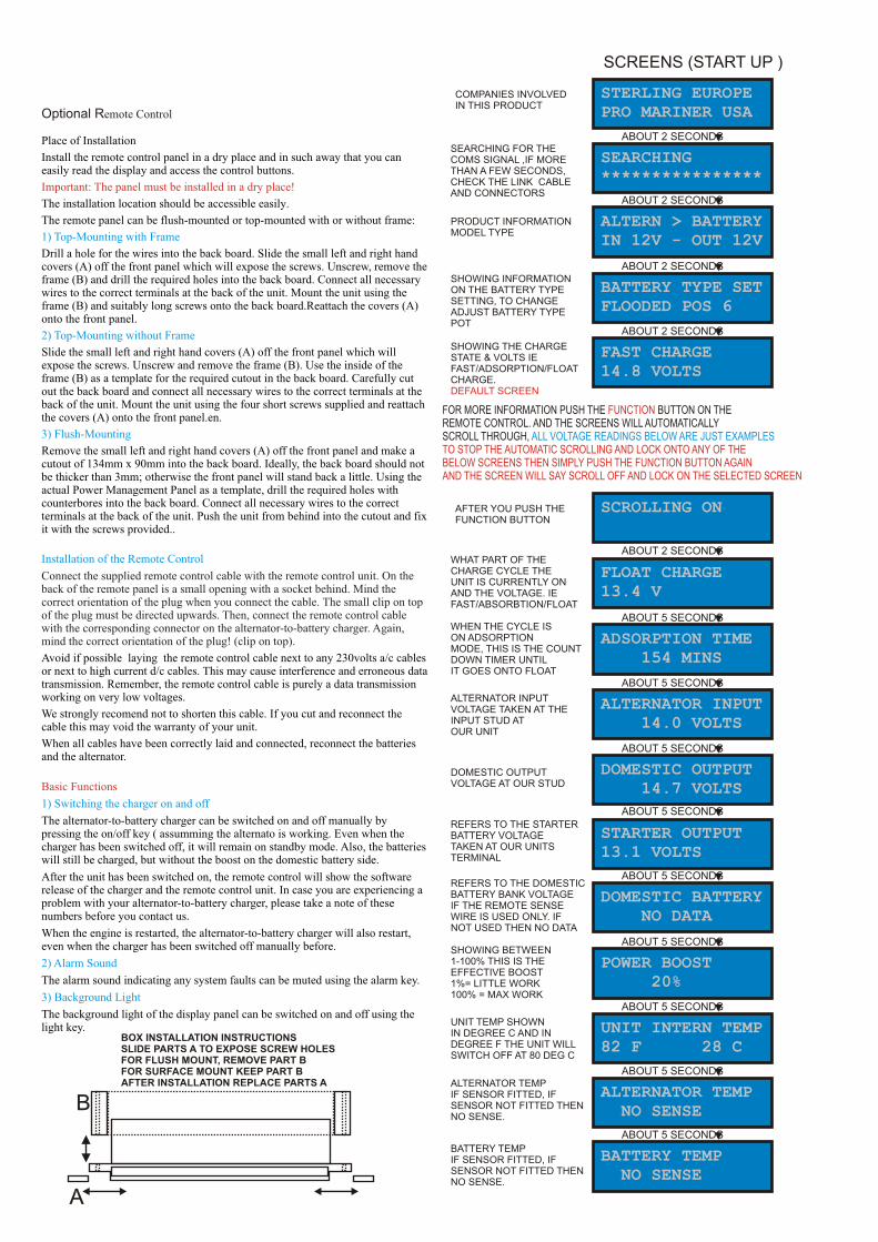
Optional Remote Control
Place of Installation
Install the remote control panel in a dry place and in such away that you can easily read the display and access the control buttons.
The installation location should be accessible easily.
The remote panel can be flush-mounted or top-mounted with or without frame:
Drill a hole for the wires into the back board. Slide the small left and right hand covers (A) off the front panel which will expose the screws. Unscrew, remove the frame (B) and drill the required holes into the back board. Connect all necessary wires to the correct terminals at the back of the unit. Mount the unit using the frame (B) and suitably long screws onto the back board.Reattach the covers (A) onto the front panel.
Slide the small left and right hand covers (A) off the front panel which will expose the screws. Unscrew and remove the frame (B). Use the inside of the frame (B) as a template for the required cutout in the back board. Carefully cut out the back board and connect all necessary wires to the correct terminals at the back of the unit. Mount the unit using the four short screws supplied and reattach the covers (A) onto the front panel.en.
Remove the small left and right hand covers (A) off the front panel and make a cutout of 134mm x 90mm into the back board. Ideally, the back board should not be thicker than 3mm; otherwise the front panel will stand back a little. Using the actual Power Management Panel as a template, drill the required holes with counterbores into the back board. Connect all necessary wires to the correct terminals at the back of the unit. Push the unit from behind into the cutout and fix it with the screws provided..
Avoid if possible laying the remote control cable next to any 230volts a/c cables or next to high current d/c cables. This may cause interference and erroneous data transmission. Remember, the remote control cable is purely a data transmission working on very low voltages.
We strongly recomend not to shorten this cable. If you cut and reconnect the cable this may void the warranty of your unit.
When all cables have been correctly laid and connected, reconnect the batteries and the alternator.
The alternator-to-battery charger can be switched on and off manually by pressing the on/off key ( assumming the alternato is working. Even when the charger has been switched off, it will remain on standby mode. Also, the batteries will still be charged, but without the boost on the domestic battery side.
After the unit has been switched on, the remote control will show the software release of the charger and the remote control unit. In case you are experiencing a problem with your alternator-to-battery charger, please take a note of these numbers before you contact us.
When the engine is restarted, the alternator-to-battery charger will also restart, even when the charger has been switched off manually before.
The alarm sound indicating any system faults can be muted using the alarm key.
The background light of the display panel can be switched on and off using the light key.
Important: The panel must be installed in a dry place!
Basic Functions
1) Top-Mounting with Frame
2) Top-Mounting without Frame
3) Flush-Mounting
Installation of the Remote Control
1) Switching the charger on and off
2) Alarm Sound
3) Background Light
Connect the supplied remote control cable with the remote control unit. On the back of the remote panel is a small opening with a socket behind. Mind the correct orientation of the plug when you connect the cable. The small clip on top of the plug must be directed upwards. Then, connect the remote control cable with the corresponding connector on the alternator-to-battery charger. Again, mind the correct orientation of the plug! (clip on top).
A
B
BOX INSTALLATION INSTRUCTIONSSLIDE PARTS A TO EXPOSE SCREW HOLESFOR FLUSH MOUNT, REMOVE PART BFOR SURFACE MOUNT KEEP PART BAFTER INSTALLATION REPLACE PARTS A
FOR MORE INFORMATION PUSH THE BUTTON ON THE REMOTE CONTROL. AND THE SCREENS WILL AUTOMATICALLY SCROLL THROUGH,
FUNCTION
TO STOP THE AUTOMATIC SCROLLING AND LOCK ONTO ANY OF THE BELOW SCREENS THEN SIMPLY PUSH THE FUNCTION BUTTON AGAIN AND THE SCREEN WILL SAY SCROLL OFF AND LOCK ON THE SELECTED SCREEN
ALL VOLTAGE READINGS BELOW ARE JUST EXAMPLES
SCROLLING ON
AFTER YOU PUSH THEFUNCTION BUTTON
SCREENS (START UP )
STERLING EUROPEPRO MARINER USA
ABOUT 2 SECONDS
SEARCHING****************
COMPANIES INVOLVED IN THIS PRODUCT
SEARCHING FOR THE COMS SIGNAL ,IF MORETHAN A FEW SECONDS,CHECK THE LINK CABLEAND CONNECTORS
ABOUT 2 SECONDS
ALTERN > BATTERYIN 12V - OUT 12V
PRODUCT INFORMATIONMODEL TYPE
ABOUT 2 SECONDS
BATTERY TYPE SETFLOODED POS 6
SHOWING INFORMATION ON THE BATTERY TYPE SETTING, TO CHANGE ADJUST BATTERY TYPEPOT
ABOUT 2 SECONDS
FAST CHARGE14.8 VOLTS
SHOWING THE CHARGE STATE & VOLTS IE FAST/ADSORPTION/FLOATCHARGE. DEFAULT SCREEN
ABOUT 2 SECONDS
STARTER OUTPUT13.1 VOLTS
REFERS TO THE STARTERBATTERY VOLTAGE TAKEN AT OUR UNITS TERMINAL
ABOUT 5 SECONDS
DOMESTIC BATTERY NO DATA
REFERS TO THE DOMESTICBATTERY BANK VOLTAGEIF THE REMOTE SENSE WIRE IS USED ONLY. IF NOT USED THEN NO DATA
ABOUT 5 SECONDS
POWER BOOST 20%
SHOWING BETWEEN1-100% THIS IS THE EFFECTIVE BOOST 1%= LITTLE WORK100% = MAX WORK
ABOUT 5 SECONDS
UNIT INTERN TEMP82 F 28 C
UNIT TEMP SHOWN IN DEGREE C AND INDEGREE F THE UNIT WILLSWITCH OFF AT 80 DEG C
ABOUT 5 SECONDS
ALTERNATOR TEMP NO SENSE
ALTERNATOR TEMPIF SENSOR FITTED, IF SENSOR NOT FITTED THEN NO SENSE.
ABOUT 5 SECONDS
BATTERY TEMP NO SENSE
BATTERY TEMPIF SENSOR FITTED, IFSENSOR NOT FITTED THEN NO SENSE.
ABOUT 5 SECONDS
FLOAT CHARGE13.4 V
WHAT PART OF THE CHARGE CYCLE THE UNIT IS CURRENTLY ON AND THE VOLTAGE. IEFAST/ABSORBTION/FLOAT
ABOUT 5 SECONDS
DOMESTIC OUTPUT 14.7 VOLTS
DOMESTIC OUTPUTVOLTAGE AT OUR STUD
ABOUT 5 SECONDS
ALTERNATOR INPUT 14.0 VOLTS
ALTERNATOR INPUTVOLTAGE TAKEN AT THEINPUT STUD ATOUR UNIT
ABOUT 5 SECONDS
ADSORPTION TIME 154 MINS
WHEN THE CYCLE ISON ADSORPTION MODE, THIS IS THE COUNTDOWN TIMER UNTILIT GOES ONTO FLOAT

ALARMS:THE UNIT IS FITTED WITH A LOT OF ALARM AND SAFETY FEATURES.UNDER NORMAL RUNNING THEY SHOULD NEVER COME ON.
THE ACTUAL ALARM WILL REMAIN ON THE SCREEN.IN THE EVENT OF SEVERAL ALARMS HAPPENING THEN THEY ARE PRIORITIZED TO SHOW THE WORST ONE
THE ALARM BUZZER CAN BE SWITCHED OFF BY PUSHING THE ALARM BUTTON ON THE REMOTE CONTROL,
HIGH VOLT DROP 1.6 V
IF THE VOLTAGE DROPBETWEEN THE UNIT OUT &THE DOM BAT ( IF SENSE WIRE IS USED ) EXCEEDS 1.6 V , THERE IS A CABLE PROBLEM
HIGH VOLTS IN15.5 VOLTS
THE STANDARD ALT S REG MUST HAVE FAILEDAND IS PUSHING OUT INEXCESS OF 15.5 V
HIGH VOLTAGE OUT15.8 VOLTS
ALARM IN THE EVENT OF THE OUTPUT VOLTAGE BEING 1 VOLT ABOVE THE DESIRED PROGRAMMED VOLTAGE
HIGH BATTERY TEMP170 F 55 C
SENSOR READING INEXCESS OF 55 DEG CCOULD BE HOT BATTSOR LOSE CONNECTION ON TERMINAL
HIGH ALT TEMP200 F 90 C
ALT TEMP SENSORSENSING IN EXCESS OF90 DEG C AT THE ALT
UNIT TEMP SENSOR FAILURE
ONE OF THE 3 INTERNALTEMP SENSORS HAS FAILED
HIGH VOLTAGE DROP 1 VOLT
THIS IS A WARNINGTHAT YOUR DOMESTICBATTERY CABLE ISTO THIN OR MAYBELOOSE
UNIT HIGH TEMP175 F 80 C
IF UNIT TEMP EXCEEDS80 DEG C THEN IT WILL SWITCH OFF THE UNIT
UNIT HOT155 F 70 C
IF THE UNIT IS ABOVE 70 DEG C BUT BELOW80 DEG C THEN THISIS A WARNING ITS GETTING HOT
HIGH V START BATT 15.5 VOLTS
COULD BE DUE TO MAJOR ALTERNATOR FAILURE OR OTHER CHARGE SOURCE
LOW V START BATT 12.8 VOLT
THIS IS A WARNINGTHAT YOUR STARTERBATTERY IS TO LOW.ALT FAILURE ??
LOW VOLTAGE OUT 12.8 VOLTS
DOMESTIC BATTERY BANK LOW, EITHEREXPECTED OR ALT / UNITFAILURE
LOW VOLTAGE IN 12.6 V
IF LOW INPUTVOLTAGE , CHECK ALT VOLTAGE TO SEE IFALT STILL WORKING ORREMOVE LARGE LOAD
OUTPUT SHORT 0.1 VOLTS
MAJOR FAULT ON THE DOMESTIC BATTERY BANK
Cable thickness is very important to avoid to much voltage drop at high currents. This could lead to a fire in the cable its always a good idea to test the unit at full power and feel all the battery cables, if you have problemstouching the cable then the temp will be in excess of about 50 deg C and this is getting to hot, add more cable to reduce the v drop and the temp will also drop
The usual only way this can happen if the alternators standard reg has failed and to much voltage is being produced at the alternator, this is a serious event and requires the engine to be switched off as soon as possible to prevent damage done to the system, we cannot stop this, only warn you. if you are somewhere where you cannot fix this problem, then please stop the engine as soon as possible and remove the alternator output cable or the alternator drive belt before continuing on . sort the alt as soon as possible
The usual only way this can happen if the alternators standard reg has failed and to much voltage is being produced at the alternator, ( as above ) however its possible the alternator is ok but the alt to battery charger regulator has failed in some way and its going to damage / over charge your batteries, in this case when the trip is activated the voltage should drop down to within safe limits ( about 14 volts ) the unit is then defective
This fault is intended to show high battery temp in excess of 55 deg c, however other factors can trigger thisalarm, for example a large amount of current going through loose/ small cable can cause the temperature on thebattery stud ( where the temp sensor is connected ) to over heat, this can set the alarm off. so in the event of this alarm activating, visit the terminal in question as soon as possible ( within a minuet or so ) and confirm if the batteries are hot or simply the terminal, in which case fix the terminal/wiring to stop this
This fault is intended to show high temp at the alternator, if this keeps going off then you should consider pipingcold air in around the back of the alternator, the alternator will then suck the air from the back of the alt through to the front , this will dramatically cool the alt down
There are 3 internal temp sensors controlling the fans inside our unit, in the event of one of them failing then thisalarm will sound, it would be a good idea to return the unit for service
This is the first stage warning that the voltage drop down your main domestic cable between the unit and the domestic batteries is getting to much ( assuming the remote sense wire is connected ) and you should be looking at increasing the amount of copper on that run of cable ( ie double it up ) . if the voltage drop goes over 1.8 volts then the unit will trip ( see above alarm )
This alarm is as it states, the unit is getting to hot and has switch off, make sure the unit is in a ventilate space and reasonablely cool, not in a engine room or a sealed cupboard. You may need to reposition the unit
This is just a pre warning saying the unit is getting into a uncomfortable condition but is still working and hashot as yet tripped out yet
Hard to say what would cause this, a alternator reg failure causing a high alt voltage would but then i would expect other alarms to go foo first, another possibility would be another charging source causing the problem , maybe a solar or wind gen or a battery charge has failed open circuit. check the alt voltage
This fault could be caused by a excessive load on the starter battery or a alternator failure
This alarm could be as a result or the alternator failure ( check alt voltage is above 13,3 volts ) if so then you could simply have a heavy load exceeding the ability of the system to sustain that load, the problemwill resolve itself when the load is relieved, and the system given a chance to recover .
I would say the most likely problem here would be the alternator failure, or possible such a large loadon the system the alternator has collapsed. remove all large loads and see if the alternator recovers , ifnot then the alternator has failed,
this would be a catastrophic short circuit on the domestic batteries, fix as soon as possible

hig
h tem
p trip
-on
/bat (flash
/alt)lo
w vo
lts in (o
n) / o
ut (flash
)h
igh
volts in
(on
) / ou
t (flash)
un
it hig
h tem
peratu
re tripflo
at mo
de
timer o
nb
oo
st / hig
h ch
arge rate o
n
senso
r fitted / b
at temp
ok
batte
ry ty
pe
info
rmatio
n a
t sta
rt up
fo
r 30 s
ecs o
nly
Rem
ote vo
ltage
senso
r(u
se either)
ALT TEMPSENSOR
0 1 2 93 84 5 7 6
BA
TT
ER
Y T
YP
ES
EL
EC
TO
R
L.E
.D. C
ha
rge
se
qu
en
ce
1) b
oo
st o
n2
) bo
os
t + tim
er o
n
3) flo
at o
n, c
om
ple
te
RO
TA
RY
SW
ITC
H F
UN
CT
ION
S
6
57
4
8
3
9
2 0
1
CO
MM
ON
NE
GA
TIV
E
ST
ER
LIN
G P
OW
ER
PR
OD
UC
TS
technology
4 AL : DUIT
RIG
AB D
L :
E
C
I
:
M
D
A
ES
N
I
Y
G
D
N
Pro
Dig
ital
remo
te co
ntro
l
Calc
ium
/ Calc
ium
B15.1
F13.6
Op
en
Lead
-Acid
B14.8
F13.3
AG
M (U
S s
pec) B
14.6
F13.7
Gel (E
ur. s
pec) B
14.4
F13.8
Seale
d L
ead
-Acid
B14.4
F13.6
A
GM
(Eu
r. sp
ec) B
14.1
F13.4
Gel (U
S s
pec) B
14.0
F13.7
BO
OS
T F
LO
AT
De-S
ulp
hatio
n C
ycle
15.5
v
POS
DO
ME
ST
ICB
AT
TE
RY
OU
TP
UT
POS
STA
RT
ER
BA
TT
ER
YO
UT
PU
T
POS
ALT
ER
NA
TO
RIN
PU
T
po
wer in
IGNITIONFEED IF REQUIRED
ST
ER
LIN
G P
OW
ER
PR
OD
UC
TS
ww
w.ste
rling-p
ow
er.co
m
1) G
el (U
S s
pe
c)
2) A
GM
(US
sp
ec
)3
) Se
ale
d L
ea
d-A
cid
4) G
el (E
ur. s
pe
c)
5) A
GM
(Eu
r. sp
ec
)6
) Op
en
Le
ad
-Ac
id7
) Ca
lciu
m / C
alc
ium
9) F
ac
tory
Se
tup
(Do
no
t us
e.)
8) D
e-S
ulp
ha
tion
(Atte
ntio
n:
Re
ad
ins
truc
tion
s b
efo
re ru
nn
ing
this
cy
cle
! (DA
NG
ER
)
AD
VA
NC
ED
4 S
TE
P
ALT
ER
NA
TO
R T
O B
AT
TE
RY
CH
AR
GE
R
DIG
ITA
LR
oH
Sco
mp
lian
t
15.5
15 1
4.5
14 1
3.5
13 1
2.5
12 v
10 s
ecs a
fter s
tart u
p b
eco
mes a
Vo
lt mete
r .
WA
RN
ING
! FAS
T C
HA
RG
ING
CO
ST
S W
AT
ER
.C
HE
CK
BA
TT
ER
Y W
AT
ER
LE
VE
L R
EG
UL
AR
LY.E
NS
UR
E B
AT
TE
RY
SE
LE
CT
OR
SW
ITC
H IS
CO
RR
EC
TLY
SE
T
FO
R Y
OU
R B
AT
TE
RY
TY
PE
.
12v 9
0 a
mp
Pro Alt C
++
++
++
remote control
1 0 2 93 84 7 5 6
++
++
++ ++
ENSURE ALL NEGS ARE COMMON
DOMESTIC BATTERY SYSTEM
remote sensor
++
9 11
L.E.D. information and alarms
4
7
de-sulphation cycleCalcium / Calcium Open Lead-Acid AGM (Euro spec) Gel (Eur. spec) Sealed Lead-Acid AGM (USA spec) Gel (US spec) )
1415161718192021
2223242526272829
30 seconds after start up this section of the l.e.d. display becomes
a voltmeter
in the event of the high voltage l.e.d. flashing in
a 3 or 4 flash sequence please see the instructions
under safety features
ENGINE STARTERBATTERY
Fuse size approx 40-50% larger than the unit rating, ie for a 100 amp unit use 150 amp fusefor a 200 amp unit use about 300 amps
Recommended fuseSterling Gold RangeFuse holder GANL1Fuse GANL###A###= 100 or 200 amp
GANL 11 X 12 mm IN
1 X 12 mm FUSED OUTPUT290 g
fuse
fuse
fuse
8
8
88
1
2
3
MINIMUM SYSTEM WIRING
BASIC INSTALLATION
Designed in UK / Made in Taiwan
STERLING POWER PRODUCTS
Advanced Intelligent digital
0.0 volt drop alternator distribution system
STERLING POWER PRODUCTS
www.sterling-power.com
technology
4DUL : RA AIT B
G LI ED :: D
C EI
SM IA G
N NYD
ProDigital
Start Batt
12 v system
Battery 2 / on line
Start Battery/on line
High alt voltage trip ( flashing )High output voltage trip ( solid )
Back feed engaged
Flash alt below 13.3 v/ on alt above 13.3 volts
On ok/Flash st-buy
Sence
Alt in
Batt 2
RoHScompliant
Pos Ign feed
IP66WATER PROOF
Split R 122Pro 120 amps
high temp trip-on/bat (flash/alt)low volts in (on) / out (flash)high volts in (on) / out (flash)unit high temperature tripfloat modetimer onboost / high charge rate on
sensor fitted / bat temp ok
battery type information at start up
for 30 secs only
Remote voltagesensor
(use either)
ALT
TE
MP
SE
NS
OR
6 7
5
4
8
3
9
2 1
0
BATTERY TYPESELECTOR
L.E.D. Charge sequence1) boost on2) boost + timer on 3) float on, complete
ROTARY SWITCH FUNCTIONS
6 5 7 4 8 3 9 2 01
COMMONNEGATIVE
STERLING POWER PRODUCTS
technology
4AL : DUIT RIG AB D L : EC I : M D
A ESN IY GD N
ProDigital
remote control
Calcium / Calcium B15.1 F13.6Open Lead-Acid B14.8 F13.3AGM (US spec) B14.6 F13.7Gel (Eur. spec) B14.4 F13.8Sealed Lead-Acid B14.4 F13.6 AGM (Eur. spec) B14.1 F13.4Gel (US spec) B14.0 F13.7 BOOST FLOAT
De-Sulphation Cycle 15.5v
PO
S
DOMESTICBATTERYOUTPUT
PO
S
STARTERBATTERYOUTPUT
PO
S
ALTERNATORINPUT
power in
IGN
ITIO
NF
EE
D IF
RE
QU
IRE
D
STERLING POWER PRODUCTSwww.sterling-power.com
1) Gel (US spec)2) AGM (US spec)3) Sealed Lead-Acid4) Gel (Eur. spec)5) AGM (Eur. spec)6) Open Lead-Acid7) Calcium / Calcium
9) Factory Setup (Do not use.)
8) De-Sulphation (Attention: Read instructions before running this cycle! (DANGER)
ADVANCED 4 STEP ALTERNATOR TO BATTERY CHARGER DIGITALRoHScompliant
15.5 15 14.5 14 13.5 13 12.5 12 v
10 secs after start up becomes a Volt meter .
WARNING! FAST CHARGING COSTS WATER.CHECK BATTERY WATER LEVEL REGULARLY.
ENSURE BATTERY SELECTOR SWITCH IS CORRECTLY SET FOR YOUR BATTERY TYPE.
12v 90 amp
Pro Alt C
+ +
++ ++
rem
ote
co
ntr
ol
6 7
5
4
8
3
9
2 0
1
+ +
++
++
How to increase the number of battery banks charged from a using a this can be done in any configuration
Pro Alt Pro Split
++
41
3
MINIMUM SYSTEM WIRING
BASIC INSTALLATION
fig 7
36
15
.5 1
5 1
4.5
14
13
.5 1
3 1
2.5
12
v
10
se
cs
afte
r sta
rt up
bec
om
es
a V
olt m
ete
r .
Boost / high charge rate onTimer onFloat modeUnit High temp tripHigh volts in (on) / out (flash)Low volts in (on) / out (flash)High temp trip-on/bat (flash/alt)Sensor fitted / bat temp ok
hig
h tem
p trip
-on
/bat (flash
/alt)lo
w vo
lts in (o
n) / o
ut (flash
)h
igh
volts in
(on
) / ou
t (flash)
un
it hig
h tem
peratu
re tripflo
at mo
de
timer o
nb
oo
st / hig
h ch
arge rate o
n
senso
r fitted / b
at temp
ok
batte
ry ty
pe
info
rmatio
n a
t sta
rt up
fo
r 30 s
ecs o
nly
Rem
ote vo
ltage
senso
r(u
se either)
ALT TEMPSENSOR
0 1 2 93 84 5 7 6
BA
TT
ER
Y T
YP
ES
EL
EC
TO
R
L.E
.D. C
ha
rge
se
qu
en
ce
1) b
oo
st o
n2
) bo
os
t + tim
er o
n
3) flo
at o
n, c
om
ple
te
RO
TA
RY
SW
ITC
H F
UN
CT
ION
S
6
57
4
8
3
9
2 0
1
CO
MM
ON
NE
GA
TIV
E
ST
ER
LIN
G P
OW
ER
PR
OD
UC
TS
technology
4 AL : DUIT
RIG
AB D
L :
E
C
I
:
M
D
A
ES
N
I
Y
G
D
N
Pro
Dig
ital
remo
te co
ntro
l
Calc
ium
/ Calc
ium
B15.1
F13.6
Op
en
Lead
-Acid
B14.8
F13.3
AG
M (U
S s
pec) B
14.6
F13.7
Gel (E
ur. s
pec) B
14.4
F13.8
Seale
d L
ead
-Acid
B14.4
F13.6
A
GM
(Eu
r. sp
ec) B
14.1
F13.4
Gel (U
S s
pec) B
14.0
F13.7
BO
OS
T F
LO
AT
De-S
ulp
hatio
n C
ycle
15.5
v
POS
DO
ME
ST
ICB
AT
TE
RY
OU
TP
UT
POS
STA
RT
ER
BA
TT
ER
YO
UT
PU
T
POS
ALT
ER
NA
TO
RIN
PU
T
po
wer in
IGNITIONFEED IF REQUIRED
ST
ER
LIN
G P
OW
ER
PR
OD
UC
TS
ww
w.ste
rling-p
ow
er.co
m
1) G
el (U
S s
pe
c)
2) A
GM
(US
sp
ec
)3
) Se
ale
d L
ea
d-A
cid
4) G
el (E
ur. s
pe
c)
5) A
GM
(Eu
r. sp
ec
)6
) Op
en
Le
ad
-Ac
id7
) Ca
lciu
m / C
alc
ium
9) F
ac
tory
Se
tup
(Do
no
t us
e.)
8) D
e-S
ulp
ha
tion
(Atte
ntio
n:
Re
ad
ins
truc
tion
s b
efo
re ru
nn
ing
this
cy
cle
! (DA
NG
ER
)
AD
VA
NC
ED
4 S
TE
P
ALT
ER
NA
TO
R T
O B
AT
TE
RY
CH
AR
GE
R
DIG
ITA
LR
oH
Sco
mp
lian
t
15.5
15 1
4.5
14 1
3.5
13 1
2.5
12 v
10 s
ecs a
fter s
tart u
p b
eco
mes a
Vo
lt mete
r .
WA
RN
ING
! FAS
T C
HA
RG
ING
CO
ST
S W
AT
ER
.C
HE
CK
BA
TT
ER
Y W
AT
ER
LE
VE
L R
EG
UL
AR
LY.E
NS
UR
E B
AT
TE
RY
SE
LE
CT
OR
SW
ITC
H IS
CO
RR
EC
TLY
SE
T
FO
R Y
OU
R B
AT
TE
RY
TY
PE
.
12v 9
0 a
mp
Pro Alt C
++
++
++
remote control
1 0 2 93 84 7 5 6
++
++
++ ++
FULL SYSTEM WIRING
(INCLUDING OPTIONAL REMOTE KIT )
ABSORBTIONTIME
FLOATINGVOLTAGE
Battery type rotary selection switchROTARY SWITCH FUNCTIONS
6 75 84 93 2 0 1
MAX. CHARGINGVOLTAGE
1) gel usa 14.0 v 1 - 10 hrs 13.7 v 2) agm 1 usa 14.35 v 1 - 8 hrs 13.35 v 3) sealed lead acid 14.4 v 1 - 12 hrs 13.6 v 4) gel euro 14.4v 12 - 24 hrs 13.8 v5) agm 2 euro 14.6 v 1 - 8 hrs 13.7 v6) open lead acid 14.8 v 1 - 8 hrs 13.3 v7) calcium/calcium 15.1 v 1 - 6 hrs 13.6 v
9) LIFEPO4 14.6v 14.4v
8) de-sulphation ( danger, read 15.5 v 4 hrs off instructions before running this cycle)
6
ENSURE ALL NEGS ARE COMMON
DOMESTIC BATTERY SYSTEM
Batterytemperature
sensorcable
( supplied )
remote sensor
1 or 2 alternatorsor battery chargeror solar cellany power sourcewithin performancevoltages
9
L.E.D. information and alarms
7
30 seconds after start up this section of the LED display becomes
a voltmeter
in the event of the high voltage l.e.d. flashing in
a 3 or 4 flash sequence please see the instructions
under safety features
100 %80706050302010
un
it pe
rform
an
ce3
0 se
cs afte
r start u
p
ENGINE STARTERBATTERY
Fuse size approx 40-50% larger than the unit rating, ie for a 100 amp unit use 150 amp fusefor a 200 amp unit use about 300 amps
Recommended fuseSterling Gold RangeFuse holder GANL1Fuse GANL###A###= 100 or 200 amp
GANL 11 X 12 mm IN
1 X 12 mm FUSED OUTPUT290 g
fuse
fuse
fuse
fuse
8
8 8
88
1
2
5REMOTE CONTROL (OPTION)
Power
Fault
Power Alarm Function Select Enter
Sterling power Pro Charge N Remote
++
4
3
fig 8
36
10
de-sulphation cycleCalcium / Calcium Open Lead-Acid AGM (Euro spec) Gel (Eur. spec) Sealed Lead-Acid AGM (USA spec) Gel (US spec) )
1415161718192021
2223242526272829
Boost / high charge rate onTimer onFloat modeUnit High temp tripHigh volts in (on) / out (flash)Low volts in (on) / out (flash)High temp trip-on/bat (flash/alt)Sensor fitted / bat temp ok

The current graph What do I expect to see from this unit and why?
Engine priority
System voltage graph:
The domestic current graph clearly shows the constant current charge between points , at position the current starts to taper off
The illustration below shows results from bench tests representing a typical until it reaches position 10. The accuracy of the software can be seen when the
split charge system with an engine battery of 100 amp hr (standard lead acid) voltage drops from the high voltage charge to the constant voltage charge
and a domestic battery of 3 x 100 amp hr (standard lead acid). The engine (float), the current only dropped 5 amps, (at position ) showing without
battery was discharged to 11 volts (about 10 engine starts) and the domestic doubt that the software program was spot on, the batteries could not accept any
bank to about 11 volts (will no longer run an inverter and is about 60% empty) . more positive charge and were clearly full. The high charge voltage is
The alternator used was a Bosch 90 amp with a standard 13.9 volt (variable) maintained between voltage positions at 14.8 volts .
regulator. The unit battery type is programmed to open lead acid. There are 2 x graphs, one is the current delivered into the batteries, and the other is various
Position shows that through the whole process the engine battery continues voltages measured on the system.
to charge and is not deprived of its charging voltage, the engine battery performance is the most important as at the end of the day it must be able to
The key points to pick up on here are: restart the engine.
The yellow trace (alternator voltage into the unit) clearly shows the system
doing its job it is designed to pull this voltage down a little to enable the standard alternator regulator to produce its full current, you can clearly see that the standard alternator voltage is at position on the voltage curve, however the input voltage has been pulled down to position , the effect on the alternator output current is full output at position - , where you can clearly see the standard alternator current without the advanced charging system taper down fast from 80 - 30 amps over the same time (from position 2-3). The advanced charging equates to about 70 amps improvement over the standard non assisted alternator.Position : This is the most interesting stage where the magic is at work, the point where the domestic battery voltage exceeds the alternator input voltage, this is what the advanced charging process is all about.
8-9 9
10
6-7
11
45
8 9
1
0 . 0 0 0
0.010
0.020
0.030
0.040
0.050
0.060
0.070
Amps
time in mins
am
ps
11
12.50
13.00
13.50
14.00
14.50
15.00
alternator input voltagestarter battery voltagedomestic battery voltage
0.080
0.090
0.100100
90
80
70
60
50
40
30
20
10
0
time in mins
volts
Domestic battery current
Starter battery bank current
Domestic battery bank current curve, with engine battery bank current curve
Engine battery bank, domestic battery bank, and alternator voltage curves
4
5
10
What a Standard alternator current curve was without the voltage amplifier
9
18
28
37
46
55
64
73
83
92
101
110
119
128
138
147
156
165
174
183
193
202
211
220
229
238
248
257
266
275
284
293
303
312
321
330
339
348
358
367
376
385
394
403
413
422
431
440
449
458
468
477
486
495
504
513
523
532
541
550
559
568
578
587
9
18
28
37
46
55
64
73
83
92
101
110
119
128
138
147
156
165
174
183
193
202
211
220
229
238
248
257
266
275
284
293
303
312
321
330
339
348
358
367
376
385
394
403
413
422
431
440
449
458
468
477
486
495
504
513
523
532
541
550
559
568
578
587
9
28
3
1
6 7

Sicherheitshinweise
Allgemeine Sicherheitsvorkehrungen
Sicherheitsvorkehrungen gegen Gasexplosionen
Sicherheitsvorkehrungen beim Umgang mit Batterien
Allgemeiner Überblick
Vor dem Einbau und dem Betrieb Ihres Sterling Das Sterling Lichtmaschinen-Batterie-Ladegerät ist ein Lichtmaschinen-Batterie-Ladegerätes lesen Sie diese vollautomatisches, elektronisches Mehrstufen-Ladesystem zum Anleitung sowie die Sicherheitshinweise auf dem Gerät gleichzeitigen Laden zwei verschiedener Batteriebänke mit Hilfe und den Batterien bitte vollständig durch. Nur eine gemäß einer oder mehrerer Lichtmaschinen. Es kombiniert einen dieser Anleitung durchgeführte, korrekte Installation stellt fortschrittlichen Dioden-Ladestromverteiler mit einer sicher, dass Ihr Lichtmaschinen-Batterie-Ladegerät leistungsfähigen Verstärkereinheit. Das Gerät besitzt einen optimal arbeiten kann. Anschluss für einen oder mehrere Lichtmaschinen und zwei
Ausgänge zum Laden zwei verschiedener Batteriebänke.
Der mit “starter battery” bezeichnete Ausgang ist eine einfache mit einer Sperrdiode versehene Durchleitung von der Lichtmaschine zur Installieren Sie das Gerät stets an einem trockenen, kühlen Starterbatterie des Bootes oder Fahrzeugs. Zur Vermeidung und gut belüfteten Ort. Jeglicher Kontakt mit Wasser oder möglicher Regelungskonflikte mit der Motorelektronik wird die großer Feuchtigkeit ist zu vermeiden. Sorgen Sie für Spannung auf diesem Ausgang nicht verstärkt.ausreichend Freiraum um die Lüfter des Gerätes, um es vor
Überhitzung zu schützen. Der mit “domestic battery” bezeichnete Ausgang arbeitet mit einem intelligenten, softwaregesteuerten Spannungsverstärker, der die Stellen Sie sicher, dass alle Kabel ausreichend dimensioniert Verbraucherbatterien bis zu fünf mal schneller und sehr viel und in gutem Zustand sind. Betreiben Sie das Gerät nicht mit effizienter als eine Standard-Lichtmaschine lädt. Darüber hinaus beschädigten oder ungeeigneten Kabeln.nehmen die Batterien bis zu 50% mehr Ladestrom auf, was die Nutzung ihrer vollen Kapazität erlaubt.
Das Lichtmaschinen-Batterie-Ladegerät sorgt für eine deutliche Das Lichtmaschinen-Batterie-Ladegerät enthält elektrische Verbesserung der Ladung der Verbraucherbatteriebank. Dabei hat Bauteile, die unter Umständen Funken erzeugen können. Um jedoch die Starterbatterie stets Priorität, und das Gerät sorgt dafür, das Risiko eines Brandes oder einer Explosion dass diese zum Starten des Motors jederzeit ausreichend geladen auszuschließen, darf das Gerät nicht in Räumen installiert ist. Die Starterbatterie wird während des Ladevorgangs stets auf werden, in denen Batterien oder leicht entzündliche Stoffe einer Spannung von mindestens 13V gehalten.aufbewahrt werden oder welche explosionsgeschützte Zusätzliche Funktionen des Gerätes schützen Ihr Bordnetz und Ihre Ausrüstung erfordern. Dies betrifft jeden Raum mit benzin-, Batterien vor möglichen Fehlern wie Überladung oder Überhitzung. gas- oder dieselbetriebenen Motoren sowie jeden Raum mit Ein Systemfehler wird durch eine Reihe von LEDs bzw. auf der entsprechenden Tanks oder Leitungen.optionalen Fernbedienung angezeigt.Bevor Sie mit der Installation des Ladegerätes beginnen,
sorgen Sie für ausreichende Belüftung. Um die Bildung Wie das Gerät arbeitetexplosiver Gase zu vermeiden, stellen Sie sicher, dass die
Batterien mindestens 4 Stunden vor Beginn der Das Lichtmaschinen-Batterie-Ladegerät maximiert die Installationsarbeiten nicht geladen wurden. Ausgangsleistung der Lichtmaschine und zieht dabei deren
Ausgangsspannung auf ca. 13V herunter. Diese (bei hohem Ausgangsstrom) anliegende, niedrige Spannung wird anschließend im Gerät auf eine höhere Spannung verstärkt, welche sich zum Wenn Sie in der Nähe einer Blei-Säure-Batterie arbeiten, sollte effektiven Laden von Batterien eignet, d.h. zwischen 14,2V und stets eine zweite Person in Rufweite sein, die im Bedarfsfall 14,8V. Dabei errechnet die intelligente Software automatisch den Hilfe leisten kann. Für den Fall dass Batteriesäure in Kontakt optimalen Ladezyklus und die Ausgleichsladezeit. Wenn die mit Haut, Augen oder Kleidung kommt, sollte stets reichlich Batterien vollständig geladen sind, geht das Gerät in eine Wasser und Seife in der Nähe bereitstehen. Tragen Sie stets Erhaltungsladung mit einer Spannung zwischen 13,5V und 13,8V.Augenschutz und schützende Kleidung. Vermeiden Sie
unbedingt, Ihre Augen zu berühren, während Sie mit einer Batterie hantieren.
ProduktmerkmaleFalls Haut oder Kleidung mit Batteriesäure in Kontakt kommen, waschen Sie diese sofort mit Wasser und Seife aus. Einfache Installation: Es könnte nicht einfacher sein. Für die Falls Batteriesäure in die Augen gerät, spülen Sie diese Basisinstallation sind nur 4 Kabelverbindungen erforderlich: eine mindestens 10 Minuten unter fließendem, kalten Wasser aus von der/den Lichtmaschine/n, eine zu jeder Batteriebank und eine und suchen unmittelbar danach einen Arzt auf. zum gemeinsamen Minuspol. Mit Ausnahme der Minuspol-
Verbindung sollten die meisten dieser Kabel an Bord bereits In der Nähe von Batterien oder Verbrennungsmotoren darf
vorhanden sein.weder geraucht werden, noch mit offenem Feuer hantiert werden. Jede Funkenbildung ist zu vermeiden. Fortschrittliche Ladetechnik: Intelligente, software-gesteuerte 4-
Stufen-Ladung der Verbraucherbatterien inklusive Temperatur-Achten Sie insbesondere darauf, dass keine metallischen Teile
kompensation.oder Werkzeuge mit den Batterien in Kontakt kommen. Dies kann einen Kurzschluss verursachen, welcher unter Keine Konflikte mit der Motorelektronik: Weil das System die ungünstigen Umständen eine Explosion auslösen könnte. Spannung der Starterbatterie nicht erhöht, sind Konflikte mit der
Motorelektronik praktisch ausgeschlossen.Bevor Sie mit der Arbeit an oder in der Nähe einer Batterie beginnen, entfernen Sie alle persönlichen Gegenstände aus Keine Veränderungen an der Lichtmaschine: Die Lichtmaschine Metall, wie z.B. Ringe, Armreifen, Halsketten, Uhren und muss nicht im geringsten modifiziert werden. Deswegen wird auch Schmuck. Eine Batterie kann bei einem Kurzschluss einen die Garantie des Motoren- bzw. Lichtmaschinenherstellers nicht hohen Strom erzeugen, welcher einen Ring oder einen beeinträchtigt.anderen Metallgegenstand stark erhitzen und schwere
Geeignet zum Anschluss mehrerer Lichtmaschinen: Im Verbrennungen verursachen kann.
Gegensatz zu anderen Systemen kann das Lichtmaschinen-Laden Sie niemals eine gefrorene Batterie. Batterie-Ladegerät gleichzeitig mit mehr als einer Lichtmaschine
betrieben werden, was weitere Installations- und Kostenvorteile bedeutet.
LICHTMASCHINEN-BATTERIE-LADEGERÄT
EINBAU- UND BEDIENUNGSANLEITUNG

Priorität der Starterbatterie: Das System stellt sicher, dass die Pluspol der Batterie! Die beiden dünnen Anschlussdrähte am Starterbatterie stets einsatzbereit bleibt. anderen Ende des Sensors schließen Sie an die mit “battery
temp” bezeichneten Geräteklemmen an. Achten Sie darauf, dass Intelligente Schutzfunktionen: Das Gerät besitzt zahlreiche
Sie den Temperatursensor nicht beschädigen! Das System ist Sicherheitsmerkmale und Fehleranzeigen. Selbst bei einem
nun in der Lage, die Batterietemperatur zu messen und die Totalausfall arbeitet das Gerät immer noch als Trenndiode.
Ladespannung entsprechend der für den gewählten Batterietyp Erweiterte Installationsmöglichkeiten: Im Lieferumfang des empfohlenen Temperaturkompensation anzupassen.Gerätes sind Temperatursensoren für die Batterie und die
Wichtig: Alle in dieser Anleitung angegebenen Spannungen Lichtmaschine enthalten. Zusätzlich kann es mit der optional
beziehen sich auf ein Umgebungstemperatur von 20°C. Bei erhältlichen Fernbedienung im Funktionsumfang erheblich
Verwendung eines Batterietemperatursensors werden die erweitert werden.
tatsächlichen Spannungen aufgrund der Temperaturkompen-sation ggf. davon abweichen.
Lichtmaschinentemperatur: Verbinden Sie das mit einem BasisinstallationKabelschuh versehene Ende des Temperatursensors mit dem Masseanschluss bzw. dem Gehäuse der Lichtmaschine. Verwenden Sie dazu keinen positiven Lichtmaschinen-Anschluss! Die beiden dünnen Anschlussdrähte am anderen Ende des Sensors schließen Sie an die mit “alt temp” bezeichneten Geräteklemmen an. Achten Sie darauf, dass Sie den Temperatursensor nicht beschädigen! Das System ist nun in der Lage, die Lichtmaschinentemperatur zu messen; bei einer Installieren Sie das Gerät an einer kühlen und gut belüfteten Temperatur von mehr als 100°C schaltet sich der Verstärkerteil Stelle in der Nähe der Lichtmaschine(n). Der Installationsort muss des Lichtmaschinen-Batterie-Ladegerätes ab, bis sich die trocken und vor starker Kondensationsfeuchtigkeit geschützt sein, Lichtmaschine wieder abgekühlt hat.da das Gerät nicht wasserdicht ist. Installieren Sie das Gerät nicht
einem geschlossenen Kasten, da dies zu Überhitzung und Spannungssensor: In der Basisinstallation misst das reduzierter Leistung des Gerätes führen kann.Lichtmaschinen-Batterie-Ladegerät alle Spannungen direkt am Das Gerät besitzt drei temperaturgesteuerte Lüfter. Diese werden Gerät. Um einen möglichen Spannungsabfall zwischen Gerät häufiger arbeiten, wenn das Gerät an einer Stelle mit hoher und Verbraucherbatterie auszugleichen, besteht die Möglichkeit, Umgebungstemperatur montiert wird.einen einfachen 0,5mm² Draht als Spannungssensor zu
Bevor Sie das Gerät mit Ihrer/Ihren Lichtmaschine(n) verbinden, verwenden. Dieser wird zwischen dem Pluspol der überprüfen Sie, dass Ihr Lichtmaschinen-Batterie-Ladegerät der Verbraucherbatterie und der mit “dom sense” bezeichneten maximalen Leistung Ihrer Lichtmaschine(n) entspricht. Geräteklemme installiert.Verbinden Sie den positiven Lichtmaschinenausgang (B+) mit dem mit “alternator input” bezeichneten Geräteanschluss. Danach Anlasser-Klemme: Einige Lichtmaschinen benötigen zum verbinden Sie die beiden Ausgangsklemmen des Gerätes mit der Starten eine Spannung an ihrem B+ Ausgang. Weil das Starter- bzw. der Verbraucherbatterie. Versichern Sie sich, dass Lichtmaschinen-Batterie-Ladegerät eine Trenndiode enthält, liegt die verwendeten Kabel für den maximalen Strom der am B+ Ausgang der Lichtmaschine jedoch keine Spannung an. Lichtmaschine(n) geeignet sind. Am besten wählen Sie eine Der Motor lässt sich dann zwar starten, aber die Lichtmaschine Kabelstärke, die mindestens für einen doppelt so hohen Strom erzeugt unter Umständen keine Spannung. Zur Lösung des geeignet sind als eigentlich erforderlich. Wenn Sie z.B. eine 70A Problems nutzen Sie die mit “starter solenoid feed” bezeichnete Lichtmaschine haben, dann verwenden Sie mindestens ein 140A Geräteklemme und verbinden diese mit der Anlasser-Klemme, Kabel. die während des Startvorgangs Spannung führt, d.h. während
der ca. 2 Sekunden, in denen der Anlasser betätigt wird. Wenn Sie nur eine Batteriebank laden möchten, benutzen Sie nur Während dieser 2 Sekunden wird über das Gerät eine 12V-den Ausgang “DOMESTIC BATTERY”. Der Ausgang “START Spannung an den B+ Anschluss der Lichtmaschine durchge-BATTERY” kann frei bleiben, ohne dass die Funktion des Gerätes leitet, was im allgemeinen ausreicht, um die Lichtmaschine beeinträchtigt wird.starten zu lassen. Danach erregt sich die Lichtmaschine selbst.
Das Gerät besitzt einen kurzen, negativen Anschlussdraht , der Benutzen Sie für diese Verbindung einen 0,5mm² Draht.
verlängert werden muss und direkt mit dem Masseanschluss (bzw. Gehäuse) der Lichtmaschine verbunden wird. Verwenden
Anschluss mehrerer Lichtmaschinen: Das Lichtmaschinen-Sie dazu ein 30A Kabel.
Batterie-Ladegerät kann mit mehreren Lichtmaschinen Wenn Sie zum Laden bisher eine Trenndiode verwendet haben, gleichzeitig betrieben werden. Verbinden Sie einfach alle dann sind die drei positiven Ladekabel bereits vorhanden. Lichtmaschinen-Ausgänge (B+) mit dem Lichtmaschinen-Ersetzen Sie einfach Ihre Trenndiode durch das Lichtmaschinen- Eingang des Gerätes. Versichern Sie sich, dass Ihr Batterie-Ladegerät, und verbinden Sie den Masseanschluss mit Lichtmaschinen-Batterie-Ladegerät der maximalen der Lichtmaschine. Gesamtleistung Ihrer Lichtmaschinen entspricht.
Wichtig: Wenn Ihre Lichtmaschine einen eigenen Batterie-Fernbedienung: Als optionales Zubehör ist eine Spannungssensor besitzt, dann muss dieser vom Batterie-Pluspol Fernbedienung lieferbar. Die Fernbedienung informiert Sie über entfernt werden und stattdessen auf den B+ Ausgang der Licht-Spannungen, Stromstärken, Temperaturen und weitere maschine gelegt werden. Dadurch werden Regelungskonflikte Kennzahlen. Ebenso werden auftretende Systemfehler zwischen Lichtmaschine und Lichtmaschinen-Batterie-Ladegerät angezeigt.ausgeschlossen.
Erweiterte Installation
Für erweiterte Funktionen und verbesserte Ladeleistung kann das Gerät mit zusätzlichen Optionen installiert werden. Beachten Sie bitte, dass die Installation dieser Zusatzoptionen für die korrekte Funktion des Gerätes grundsätzlich nicht erforderlich sind.
Batterietemperatur: Verbinden Sie das mit einem Kabelschuh versehene Ende des Temperatursensors mit dem Minuspol der Verbraucherbatterie. Verwenden Sie dazu nicht den
Wichtig: Diese Installationshinweise beziehen sich auf die Kabelverbindungen, die zur korrekten Installation des Lichtmaschinen-Batterie-Ladegerätes erforderlich sind. Bei einem bereits existierenden Bordnetz ist es ggf. erforderlich, einige der bis dato genutzten Kabelverbindungen zu entfernen.
(10)
(7)
(4)
(2)
(5)
(6)

Spannungsanzeige.Wahl des BatterietypsJetzt fängt die LED1 an zu leuchten sowie eventuell andere
Stellen Sie den Typ Ihrer Verbraucherbatterie mit Wahlschalter LEDs, welche Störungen oder Stati anzeigen.ein. Das Gerät verfügt über Einstellmöglichkeiten für 8
Nach Abschluss der Startphase brennt die LED 1 kontinuierlich verschiedene Batterietypen:grün und zeigt damit an, dass sich das Gerät in der Hochstrom-ladephase befindet und die Verbraucherbatterie eine verstärkte Ladung erhält. Damit steigt gleichzeitig die an der Lichtmaschine anliegende Last.
Die Spannung am Ausgang zur Verbraucherbatterie wächst nun kontinuierlich bis zum Erreichen der Ladeschlussspannung für den eingestellten Batterietyp. Danach wird die Spannung auf gleichem Niveau gehalten (14,1V bis 15,1V); zusätzlich brennt die gelbe “Time Control” LED 2. Die intelligente Software des Gerätes berechnet automatisch die optimale Ausgleichsladezeit (zwischen 1 und 24 Stunden).
POS 1: GEL USA - Batterien, welche in den USA hergestellt Wenn die Batterien vollständig geladen sind, wird die Spannung wurden. Hier gelten abweichende Ladeschlussspannungen. abgesenkt, und es liegt eine konstante Erhaltungsladespannung Ladeschlussspannung U1 bei 14,0V und Erhaltungsladung bei an (13,3V bis 13,8V).13,7V.
Sobald in der Erhaltungsladephase die Spannung der POS 2: AGM USA - Einstellung für AGM Batterien, welche in den Verbraucherbatterie unter 12V absinkt (z.B. aufgrund einer hohen USA hergestellt wurden. Ladeschlussspannung U1 bei 14,35V Stromentnahme), beginnt der gesamte Ladezyklus von vorn.und Erhaltungsladung U2 bei 13,35V.
POS 3: GESCHLOSSENE SÄURE - Einstellung für geschlossene (nicht nachzufüllende) Blei-Säure-Batterien. FehlersucheLadeschlussspannung U1 bei 14,4V und Erhaltungsladung U2
Gerät zeigt keinerlei Aktivität (keine LEDs)bei 13,6V.Nachdem Sie die Maschine gestartet haben, überprüfen Sie die POS 4: GEL EURO - Einstellung für Gel-Batterien, welche nach Eingangsspannung am Lichtmaschinen-Anschluss des Gerätes. der europäischen Spezifikation von Exide gebaut wurden. Hier sollten mindestens 13V anliegen. Wenn Sie überhaupt keine Ladeschlussspannung U1 von 14,4V und Erhaltungsladung U2 Spannung messen können, kann es sein, dass Ihre von 13,8V. Besonderheit ist hier, dass die Erhaltungsladung U2 Lichtmaschine keine Spannung abgibt, weil sie zunächst extern erst nach frühestens 12 Std. einsetzt. Das ist so von Exide erregt werden muss. (Siehe “Erweiterte Installation”.) Verbinden empfohlen.Sie in diesem Fall die mit “STARTER SOLENOID” bezeichnete
POS 5: AGM EURO - Einstellung für AGM Batterien nach Klemme mit dem positiven Anschluss des Starter-Relais.europäischen Standard. Ladeschlussspannung von 14,6V und
Wenn die Eingangsspannung am Gerät 13V oder mehr beträgt Erhaltungsladung von 13,7V.und dennoch keine der LEDs leuchtet, prüfen Sie bitte die interne
POS 6: OFFENE BLEI SÄURE - Einstellung für Blei-Säure Sicherung des Gerätes und ersetzen Sie diese, wenn Batterien, deren Verschlusskappen zum Nachfüllen von Wasser erforderlich. Falls die neue Sicherung anschließend erneut geöffnet werden können. Ladeschlussspannung U1 von 14,8V durchbrennt, setzen Sie sich bitte mit dem Sterling Kundendienst und Erhaltungsladung U2 von 13,3V in Verbindung.
Gerät verstärkt die Spannung nicht
Die meisten Lichtmaschinenregler sind auf eine Ausgangsspannung zwischen 13,6V und 14,4V eingestellt. Wenn
POS 7: KALZIUM-KALZIUM - Einstellung für Batterien mit einer Ihr Lichtmaschinenregler nicht innerhalb dieser Grenzen arbeitet Silber Kalzium, Kalzium-Kalzium Legierung. und die Spannung unter 13,3V regelt, kann das Lichtmaschinen-Ladeschlussspannung von 15,1V und Erhaltungsladung von Batterie-Ladegerät die Spannung unter Umständen nicht 13,6V. verstärken. Bitte reparieren oder ersetzen Sie Ihren
Standardregler mit einem Regler, welcher diesen Standard-POS 8: DESULFATIERUNG - Einstellung nur für offene Blei- Anforderung entspricht.Säure-Batterien zur Desulfatierung der Bleiplatten. Ladeschlussspannung U1 von 15,5V für 4 Stunden. Anschließend normale Ladeschlussspannung der Lichtsmaschine ohne Boost Anhang 1:Funktion. LED Anzeigen und FehlermeldungenDie optimale Ausgleichsladezeit für die einzelnen Batterietypen
LED 14 - BOOST (grün)wird mit jedem neuen Ladezyklus automatisch neu berechnet.konstant: Maximalstromladephase (LED 15 aus)blinkend: Ladepause.POS 9: LITHIUM FERRO POLYMER
Ladeschlussspannung von 14.6V und Erhaltungsladung von LED 15 - TIMER (gelb)14.4V. Nur in Verbindung mit einem Batterie-Management-Die Ladeschlussspannung wurde erreicht bzw. wird in Kürze System. Keine Temperaturkompensation!erreicht. Sie brennt immer zusätzlich zu LED 1. Die Ausgleichsladungsphase kann zwischen 1 und 24 Std. dauern, je nach eingestelltem Batterietyp und berechneter Zeit.
Einschalten und TestLED 16 - FLOAT/POWERPACK (grün)Sobald das Gerät vollständig angeschlossen ist, erfasst es die Die Augleichsladungsphase ist beendet und die Batterien sind von der Lichtmaschine kommende Eingangsspannung. Wenn die vollständig geladen. Sie bleibt an, bis das Gerät ausgeschaltet Lichtmaschine Spannung erzeugt, wird das Lichtmaschinen-wird bzw. bis ein neuer Ladezyklus beginnt.Batterie-Ladegerät aktiv und zwar in folgender Abfolge:
Zuerst wird die Softwareversion im Hexadezimalcode für 2 Sek. LED 17 BAT TEMP HIGH (rot)angezeigt. Anschließend leuchten alle LEDs für 2 Sek. konstant: Die Batterie hat eine Temperatur von 55°C
überschritten. Das Gerät hat abgeschaltet und kann erst durch Danach wird der eingestellte Batterietyp durch 1 LED für 5 Sek. einen Neustart wieder aktiviert werden. Überprüfen Sie sofort, angezeigt. Die Batterietypenanzeige wird anschließend zur reinen
(6)
Wichtig: Schnelles Laden kostet Wasser! Prüfen Sie den Wasserstand in Ihren Batterien regelmäßig und füllen Sie Wasser nach wenn erforderlich. Nicht zu viel Wasser einfüllen!
6 7
5
8
4
9
3
2
0
1BATTERY TYPE
SELECTOR

warum die Batterie zu heiß geworden ist. REMOTE CONTROL (optional)
Anschluss für die optionale Fernbedienung.blinkend: Die maximal erlaubte Lichtmaschinentemperatur von 90°C wurde überschritten. Das Gerät ist im Standby, bis die Temperatur einen Normalwert erreicht hat.
2x blinkend - pause: Einer der 3 internen Temperatursensoren ist defekt. Das Gerät muss zur Reparatur in eine Sterling Servicewerkstatt.
3x blinkend - pause: Überspannung an der Starterbatterie.
4x blinkend - pause: Hoher Spannungsabfall zwischen Ausgang und Verbraucherbatterie
5x blinkend - pause: Zu hoher Spannungsabfall zwischen Ausgang und Verbraucherbatterie. Boost ist abgeschaltet.
LED 20 - HIGH TEMP TRIP (ON) / BOOST (FLASH)konstant: Maximal erlaubte interne Temperatur wurde überschritten. Das Gerät ist abgeschaltet und kann nur durch einen Neustart wieder reaktiviert werden.
blinkend: Der Boost-Kühlkörper hat die maximal erlaubte Temperatur überschritten. Der Boost Modus ist deaktiviert und das Gerät im Standby, bis die Temperatur wieder auf ein Normalniveau abgesunken ist.
In beiden Fällen überprüfen Sie unbedingt die Raumtemperatur und die Belüftung des Gerätes. Überprüfen Sie, ob alle 4 Ventilatoren im Gerät funktionieren.
LED 21 - SENSOR FITTED / BAT TEMP OK (grün)Batterietemperatursensor ist angeschlossen und die Temperatur ist im erlaubten Bereich.
Anhang 2: Geräteanschlüsse
TO DOMESTIC BATTERY BANK
Anschluss für das positive Ladekabel zur Verbraucherbatterie.
MAIN ALTERNATOR INPUT
Positive Eingangsklemme zum B+ Anschluss der Lichtmaschine.
TO ENGINE STARTER BATTERY
Anschluss für das positive Ladekabel zur Starterbatterie.
NEGATIVE CABLE
Verlängern Sie dieses Kabel zum Masseanschluss der Lichtmaschine. Es sollte ein 60A Kabel verwendet werden.
STARTER SOLENOID (optional)
Optionaler Anschluss für das Anlasser-Relais. (Siehe “Erweiterte Installation”.) Nur im Bedarfsfall zu verwenden!
REMOTE DOM SENSE (optional)
Optionaler Anschluss für den Spannungssensor der Verbraucherbatterie. (Siehe “Erweiterte Installation”.)
ALTERNATOR TEMP SENSOR (optional)
Optionaler Anschluss für den Lichtmaschinen-Temperatursensor.
BATTERY TEMP SENSOR (optional)
Optionaler Anschluss für den Batterie-Temperatursensor.
Überprüfen Sie die Lichtmaschinenspannung; falls erforderlich, stoppen Sie die Maschine so bald wie möglich und trennen die Lichtmaschine vom Lichtmaschinen-Batterie-Ladegerät. Andernfalls besteht die Gefahr, dass Sie Ihre Batterien überladen und zerstören!
Stellen Sie sicher, dass alle verwendeten Kabelausreichend dimensioniert sind!
(5)
(2)
(4)
(7)
(10)
(6)
MaximalladungAusgleichsladungErhaltungsladungAbschaltung w/ hoher Temp.
Unterspannung (siehe Anl.)Gerät zu warm (standby)Abschaltung w/ Überspannung
Batterietemp.sensor ok
1415161718192021
Batte
rie T
yp
Info
rmatio
ners
ch
ein
t nu
r für 1
0 S
ek.
wäh
ren
d d
es S
tarts
15.5
15 1
4.5
14 1
3.5
13 1
2.5
12 v
10 S
ek. n
ach
dem
Sta
rt wird
es e
in V
oltm
ete
r
14.8 13.3 14.6 13.7 14.4 13.8 14.4 13.6 14.1 13.4 14.0 13.7
15.1 13.6K
alzium
/ Kalziu
m
offen
e Blei-S
äure
AG
M (E
UR
O)
GE
L (E
UR
O)
gesch
lossen
e Säu
re A
GM
(US
A)
GE
L (U
SA
)
En
tsulfatieru
ng
Offen
e Blei-S
äure + G
EL
Eu
ro = L
iFeP
o4 14.6 14.4
x 2 fü
r 24
V G
erä
te
x 2 für 24 V Gerät
Welche Kabeldurchmesser in mm²bis zu Kabellänge 0-1.5 m 1.5 - 4 m 0-25 amps 6 mm² 10 mm² 25-45 amps 16 mm² 25 mm² 45-85 amps 25 mm² 35 mm² 85-125 amps 35 mm² 50 mm² 125- 180 amps 50 mm² 70 mm² 180 - 330 amps 70 mm² 90 mm²
Wenn Sie ein starkes Kabel nicht erwerben können, dann nehmen Sie 2x das schwächere Kabel. Viele Probleme entstehen durch zu hohen Spannungsabfall in den Kabeln. Deshalb entscheiden Sie sich bitte immer für das stärkere Kabel.
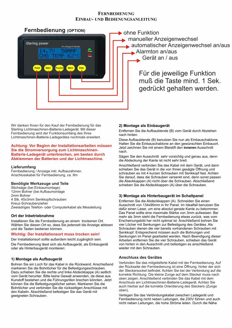
Fernbedienung (OPTION)
Für die jeweilige Funktionmuß die Taste mind. 1 Sek.gedrückt gehalten werden.
ohne Funktion manueller Anzeigenwechsel automatischer Anzeigenwechsel an/aus Alarmton an/aus Gerät an / aus
FERNBEDIENUNG
EINBAU- UND BEDIENUNGSANLEITUNG
Wir danken Ihnen für den Kauf der Fernbedienung für das Sterling Lichtmaschinen-Batterie-Ladegerät. Mit dieser Fernbedienung wird der Funktionsumfang des Ihres Lichtmaschinen-Batterie-Ladegerätes nochmals erweitert.
LieferumfangFernbedienung / Anzeige inkl. Aufbaurahmen.Anschlusskabel für Fernbedienung, ca. 8m
Benötigte Werkzeuge und TeileStichsäge (bei Einbaumontage)12mm Bohrer (bei Aufbaumontage2mm Bohrer4 Stk. 45x3mm SenkkopfschraubenKreuz-SchraubenzieherZweiadriges Telefon- oder Computerkabel als Messleitung
Achtung: Vor Beginn der Installationsarbeiten müssen Sie die Stromversorgung zum Lichtmaschinen-Batterie-Ladegerät unterbrechen, am besten durch Abklemmen der Batterien und der Lichtmaschine.
2) Montage als Einbaugerät
Entfernen Sie die Aufbaublende (B) vom Gerät durch Abziehen nach hinten.
Diese Aufbaublende (B) benutzen Sie nun als Einbauschablone. Halten Sie die Einbauschablone an den gewünschten Einbauort. Jetzt zeichnen Sie mit einem Bleistift den inneren Ausschnitt nach.
Sägen Sie den Ausschnitt sehr vorsichtig und genau aus, denn die Abdeckung der Kante ist nicht sehr breit.
Anschließend verbinden Sie das Kabel mit dem Gerät, und dann schieben Sie das Gerät in die von Ihnen gesägte Öffnung und schrauben es mit 4 kurzen Schrauben mit Senkkopf fest. Achten Sie darauf, dass die Schrauben versenkt sind, denn sonst passen die Abeckkappen (A) nicht über die Schrauben. Abschließend schieben Sie die Abdeckkappen (A) über die Schrauben.
3) Montage als Hinterbaugerät im Schaltpanel
Entfernen Sie die Abdeckkappen (A). Schneiden Sie einen Ausschnitt von 134x90mm in Ihr Panel. Im Idealfall benutzen Sie dafür einen Laser, um eine absolut gerade Kante zu bekommen. Das Panel sollte eine maximale Stärke von 3mm aufweisen. Bei
Ort der Inbetriebnahme mehr als 3mm steht die Fernbedienung etwas zurück, was vom Erscheinungsbild her nicht optimal ist. Anschließend bohren Sie Installieren Sie die Fernbedienung an einem trockenen Ort. vier Löcher mit Senkungen zur Befestigung des Gerätes. Als Wählen Sie diesen Ort so, dass Sie jederzeit die Anzeige ablesen Schrauben dienen die vier bereits vorhandenen Schrauben mit und die Tasten bedienen können. Senkkopf. Entsprechend müssen auch die Bohrungen und Senkungen im Panel gearbeitet werden. Nach Beendigung dieser
Der Installationsort sollte außerdem leicht zugänglich sein. Arbeiten entfernen Sie die vier Schrauben, schieben das Gerät von hinten in den Ausschnitt und befestigen es anschließend Die Fernbedienung lässt sich als Aufbaugerät, als Einbaugerät wieder mit den Schrauben.oder als Hinterbaugerät montieren:
1) Montage als Aufbaugerät
Bohren Sie ein Loch für das Kabel in die Rückwand. Anschießend markieren Sie die Bohrlöcher für die Befestigungsschrauben. Dazu schieben Sie die rechte und linke Abdeckkappe (A) seitlich vom Gerät herunter. Bitte keine Gewalt anwenden, da diese aus Kunstoff bestehen und die Führungsrillen brechen könnten. Jetzt können Sie die Befestigungslöcher sehen. Markieren Sie die Bohrlöcher und verbinden Sie die rückseitigen Anschlüsse mit den Kabeln. Abschließend befestigen Sie das Gerät mit
Verlegen Sie das Verbindungskabel zwischen Ladegerät und geeigneten Schrauben.Fernbedienung nicht neben Leitungen, die 230V führen und auch nicht neben Leitungen, die hohe Ströme leiten. Durch die Nähe
Wichtig: Der Installationsort muss trocken sein!
Anschluss des Gerätes
Verbinden Sie das mitgelieferte Kabel mit der Fernbedienung. Auf der Rückseite der Fernbedienung ist eine Öffnung, hinter der sich der Steckersockel befindet. Achten Sie bei der Verbindung auf die korrekte Richtung. Die kleine Zunge auf dem Stecker muss nach oben zeigen. Anschließend verbinden Sie das Kabel mit dem Anschluss am Lichtmaschinen-Batterie-Ladegerät. Achten Sie auch hierbei auf die korrekte Orientierung des Steckers (Zunge oben).

kann es zu Störungen in der Datenübertragung kommen. Es handelt sich um eine reine Datenverbindung, die mit sehr geringen Spannungen arbeitet.
Wir empfehlen Ihnen dringend, dieses Kabel nicht zu kürzen. Im Falle einer Auftrennung und Wiederverbindung des Kabels erlischt die Gewährleistung.
Wenn alle Kabel korrekt verlegt und verbunden sind, stellen Sie die zuvor unterbrochene Stromversorgung (Batterien, Lichtmaschine) wieder her.
Gerätefunktionen
Durch Drücken der Taste kann die Funktion des Ladegerätes manuell ein- und ausgeschaltet werden. Auch bei ausgeschalteter Ladefunktion bleibt das Ladegerät in Bereitschaft, arbeitet jedoch nicht. Die Fernbedienung zeigt in diesem Fall die Spannung der Verbraucherbatterie an.
Nach dem Einschalten des Gerätes zeigt das Gerät zunächst für einige Sekunden die Software-Version des Ladegerätes und der Fernbedienung an. Sollte es zu einem technischen Problem mit dem Gerät kommen und Sie möchten uns kontaktieren, notieren Sie bitte vorher die angezeigten Software-Versionen.
Wenn Sie die Ladefunktion manuell ausgeschaltet haben, wird diese bei einem Neustart des Motors nicht automatisch wieder eingeschaltet.
Grundfunktionen
1) Ein- und Ausschalten der Ladefunktion
power
AB
EIN
BA
U D
ER
FE
RN
BE
DIE
NU
NG
EN
TF
ER
NE
N S
IE D
IE S
EIT
EN
TE
ILE
AA
LS
EIN
BA
UG
ER
ÄT
EN
TF
ER
NE
N S
IE T
EIL
BA
LS
AU
FB
AU
GE
RÄ
T B
EH
ALT
EN
SIE
TE
IL B
NA
CH
BE
FE
ST
IGU
NG
SC
HIE
BE
N S
IE D
IE S
EIT
EN
TE
ILE
A W
IED
ER
Z
UR
ÜC
K.
Zur Anzeige von weiteren Informationen drücken Sie bitte die“Select” Taste für jeweils min. 1 Sek. Möchten Sie, dass die Anzeigeautomatisch wechselt, drücken Sie bitte die “Function” Taste.Nun wechselt die Anzeige automatisch alle 5 Sek.Zum Ausschalten dieser Funktion drücken Sie bitte nochmals die“Function” Taste.
SCROLLING ON
Nach dem Drückender “Function” Taste
ANZEIGEN (START UP )
STERLING EUROPEPRO MARINER USA
ca. 2 Sek.
SEARCHING****************
HERSTELLERFIRMEN
Kontaktaufnahme zumHauptgerät. Sollte dieseslänger als ein paar Sek.dauern, dann überprüfenSie bitte die Kabelverb.
ca. 2 Sek.
ALTERN > BATTERYIN 12V - OUT 12V
Produktinformationund Typ
ca. 2 Sek.
BATTERY TYPE SETFLOODED POS 6
EingestellterBatterietyp
ca. 2 Sek.
FAST CHARGE14.8 VOLTS
Ladestufenanzeigeund SpannungStandard Anzeige
ca. 2 Sek.
STARTER OUTPUT13.1 VOLTS
Starter Ausgangs-spannung am Gerät
ca. 5 Sek.
DOMESTIC BATTERY NO DATA
VerbraucherbatterieSpannung. Nur ange-zeigt, wenn entspr.Kabel angeschlossen.
ca. 5 Sek.
POWER BOOST 20%
Anzeige der Boost-Leistung.
ca. 5 Sek.
UNIT INTERN TEMP82 F 28 C
Interne Gerätetem-peratur. Anzeige inFahrenheit und Celcius.
ca. 5 Sek.
ALTERNATOR TEMP NO SENSE
Anzeige der Lichtma-schinentemperatur.Nur wenn Sensorangeschlossen ist.
ca. 5 Sek.
BATTERY TEMP NO SENSE
Anzeige der Batterie-Temperatur.Nur wenn Sensorangeschlossen ist.
ca. 5 Sek.
FLOAT CHARGE13.4 V
Anzeige der Ladestufeund der Spannung
ca. 5 Sek.
DOMESTIC OUTPUT 14.7 VOLTS
Verbraucher Ausgangs-Spannung am Gerät
ca. 5 Sek.
ALTERNATOR INPUT 14.0 VOLTS
Eingangsspannungam Gerät
ca. 5 Sek.
ADSORPTION TIME 154 MINS
Anzeige nur, wenn inAusgleichsladung.Anzeige der verbleiben-den Minuten.

WARN - HINWEISE:Diese Anzeigen sollten nur erscheinen, wenn es ein Problem beim Betrieb gibt.
Sollten mehrere kritische Fehler auf einmal passieren, dann wird der wichtigste Alarm angezeigt. Der Alarmton kann durch drücken der Alarm Taste unterbrochen werden.
HIGH VOLT DROP 1.6 V
HIGH VOLTS IN15.5 VOLTS
HIGH VOLTAGE OUT15.8 VOLTS
HIGH BATTERY TEMP170 F 55 C
HIGH ALT TEMP200 F 90 C
UNIT TEMP SENSOR FAILURE
UNIT HIGH TEMP175 F 80 C
UNIT HOT155 F 70 C
HIGH V START BATT 15.5 VOLTS
LOW V START BATT 12.8 VOLT
LOW VOLTAGE OUT 12.8 VOLTS
LOW VOLTAGE IN 12.6 V
Der Spannungsabfall zwischen dem Ausgang der Verbraucherbatterie und der Batterie selbst ist zu hoch.Der Boost ist abgeschaltet. Erhöhen Sie den Kabeldurchmesser.
Die Eingangsspannung ist zu hoch. Der Boost ist abgeschaltet. Wahrscheinlich ist der Standard-Regler defekt. Stoppen sie sofort die Ladung der Batterien.
Die Ausgangsspannung ist zu hoch. Der Boost ist abgeschaltet. Entweder erzeugt ein anderes Ladegerät eine erhöhte Spannung oder dieses Gerät ist defekt.
Die Temperatur der Batterie ist zu hoch. Stoppen sie die Ladung um eine weitere Schädigung der Batterie zu vermeiden. Kontrollieren Sie die Temperatur der Batterie umgehend. Das Gerät ist abgeschaltet.
Die Lichtmaschinentemperatur ist zu hoch. Das Gerät ist im Standby Modus und wartet auf ein Abkühlen der Lima. Verbessern Sie die Kühlung der Lima!
Ein interner Temperatursensor ist defekt. Das Gerät muß zur Untersuchung in eine Sterling Servicewerkstatt.
Die maximale interne Temperatur ist überschritten worden. Das Gerät ist abgeschaltet. Überprüfen Sie die Belüftung.
Die normale Arbeitstemperatur ist überschritten worden. Das Gerät ist in Standby, bis die Temperatur wieder im normalen Bereich ist. Überprüfen Sie die Belüftung des Einbauortes.
Die Starterbatteriespannung ist zu hoch. Da das Gerät keinen Einfluß auf diese Batterie h at, schaltet das Gerät nicht ab. Überprüfen Sie sofort, warum so eine hohe Spannung an der Starterbatterie anliegt.
Die Spannung der Starterbatterie ist sehr niedrig. Sotte die Warnung nicht erlöschen, überprüfen Sie bitte die Batterie und die Verkabelung.
Die Verbraucherbatteriespannung ist sehr gering. Eventuell war die Batterie sehr stark Entladen und braucht eine gewisse Zeit, bis die Spannung ansteigt. Erlischt die Anzeige nicht, überprüfen Sie bitte die Kabel und Spannungen.
Die Eingangsspannung ist zu gering. Sollte diese Warnung anhalten, dann überprüfen Sie bitte die Funktion der Lichtmaschine und des Standardreglers.

hig
h tem
p trip
-on
/bat (flash
/alt)lo
w vo
lts in (o
n) / o
ut (flash
)h
igh
volts in
(on
) / ou
t (flash)
un
it hig
h tem
peratu
re tripflo
at mo
de
timer o
nb
oo
st / hig
h ch
arge rate o
n
senso
r fitted / b
at temp
ok
batte
ry ty
pe
info
rmatio
n a
t sta
rt up
fo
r 30 s
ecs o
nly
Rem
ote vo
ltage
senso
r(u
se either)
ALT TEMPSENSOR
0 1 2 93 84 5 7 6
BA
TT
ER
Y T
YP
ES
EL
EC
TO
R
L.E
.D. C
ha
rge
se
qu
en
ce
1) b
oo
st o
n2
) bo
os
t + tim
er o
n
3) flo
at o
n, c
om
ple
te
RO
TA
RY
SW
ITC
H F
UN
CT
ION
S
6
57
4
8
3
9
2 0
1
CO
MM
ON
NE
GA
TIV
E
ST
ER
LIN
G P
OW
ER
PR
OD
UC
TS
technology
4 AL : DUIT
RIG
AB D
L :
E
C
I
:
M
D
A
ES
N
I
Y
G
D
N
Pro
Dig
ital
remo
te co
ntro
l
Calc
ium
/ Calc
ium
B15.1
F13.6
Op
en
Lead
-Acid
B14.8
F13.3
AG
M (U
S s
pec) B
14.6
F13.7
Gel (E
ur. s
pec) B
14.4
F13.8
Seale
d L
ead
-Acid
B14.4
F13.6
A
GM
(Eu
r. sp
ec) B
14.1
F13.4
Gel (U
S s
pec) B
14.0
F13.7
BO
OS
T F
LO
AT
De-S
ulp
hatio
n C
ycle
15.5
v
POS
DO
ME
ST
ICB
AT
TE
RY
OU
TP
UT
POS
STA
RT
ER
BA
TT
ER
YO
UT
PU
T
POS
ALT
ER
NA
TO
RIN
PU
T
po
wer in
IGNITIONFEED IF REQUIRED
ST
ER
LIN
G P
OW
ER
PR
OD
UC
TS
ww
w.ste
rling-p
ow
er.co
m
1) G
el (U
S s
pe
c)
2) A
GM
(US
sp
ec
)3
) Se
ale
d L
ea
d-A
cid
4) G
el (E
ur. s
pe
c)
5) A
GM
(Eu
r. sp
ec
)6
) Op
en
Le
ad
-Ac
id7
) Ca
lciu
m / C
alc
ium
9) F
ac
tory
Se
tup
(Do
no
t us
e.)
8) D
e-S
ulp
ha
tion
(Atte
ntio
n:
Re
ad
ins
truc
tion
s b
efo
re ru
nn
ing
this
cy
cle
! (DA
NG
ER
)
AD
VA
NC
ED
4 S
TE
P
ALT
ER
NA
TO
R T
O B
AT
TE
RY
CH
AR
GE
R
DIG
ITA
LR
oH
Sco
mp
lian
t
15.5
15 1
4.5
14 1
3.5
13 1
2.5
12 v
10 s
ecs a
fter s
tart u
p b
eco
mes a
Vo
lt mete
r .
WA
RN
ING
! FAS
T C
HA
RG
ING
CO
ST
S W
AT
ER
.C
HE
CK
BA
TT
ER
Y W
AT
ER
LE
VE
L R
EG
UL
AR
LY.E
NS
UR
E B
AT
TE
RY
SE
LE
CT
OR
SW
ITC
H IS
CO
RR
EC
TLY
SE
T
FO
R Y
OU
R B
AT
TE
RY
TY
PE
.
12v 9
0 a
mp
Pro Alt C
++
++
++
remote control
1 0 2 93 84 7 5 6
++
++
++ ++
ANSCHLUSS - DIAGRAM
ABSORBTIONTIME
FLOATINGVOLTAGE
Batterie Typ EinstellungenROTARY SWITCH FUNCTIONS
6 75 84 93 2 0 1
MAX. CHARGINGVOLTAGE
1) gel usa 14.0 v 1 - 10 hrs 13.7 v 2) agm 1 usa 14.35 v 1 - 8 hrs 13.35 v 3) sealed lead acid 14.4 v 1 - 12 hrs 13.6 v 4) gel euro 14.4v 12 - 24 hrs 13.8 v5) agm 2 euro 14.6 v 1 - 8 hrs 13.7 v6) open lead acid 14.8 v 1 - 8 hrs 13.3 v7) calcium/calcium 15.1 v 1 - 6 hrs 13.6 v
9) LIFEPO4 14.6 v 1 hr 14.4 v
8) de-sulphation ( danger, read 15.5 v 4 hrs off instructions before running this cycle)
6
Vergewissern Sie sich, dass alle negativen Anschlüssen
Verbraucher Batterien
BatteryTemperatur
Sensor(beliegend)
remote sensor
Es können 1 oder2 Lichtmaschinenangeschlossen werden.Die maximale Leistungdes Gerätes darf nichtüberschritten werden.
9
L.E.D. information and alarms
7
30 Sek. nach dem Startwird diese Anzeige zu einem
Voltmeter
im Falle einer Über-Spannung, bitte lesen Sie
Einzelheiten in dieser Anlei-tung nach!
100 %80706050302010
un
it pe
rform
an
ce3
0 se
cs afte
r start u
p
STARTER BATTERIE
Sicherung muß ca. 50% höher ausgelegtwerden, als die maximal Belastung.Z.B. bei einer 100A Lichtmaschine, 150A
Empfohlene SicherungenSterling Gold RangeFuse holder GANL1Fuse GANL###A###= 100 or 200 amp
GANL 11 X 12 mm IN
1 X 12 mm FUSED OUTPUT290 g
fuse
fuse
fuse
fuse
8
8 8
88
1
2
5FERNBEDIENUNG (OPTION)
Power
Fault
Power Alarm Function Select Enter
Sterling power Pro Charge N Remote
++
4
3
fig 8
36
10
L.E.D. information and alarms
de-sulphation cycleCalcium / Calcium Open Lead-Acid AGM (Euro spec) Gel (Eur. spec) Sealed Lead-Acid AGM (USA spec) Gel (US spec) )
1415161718192021
2223242526272829
Boost / high charge rate onTimer onFloat modeUnit High temp tripHigh volts in (on) / out (flash)Low volts in (on) / out (flash)High temp trip-on/bat (flash/alt)Sensor fitted / bat temp ok

STERLING POWER PRODUCTS LTDWebsite: www.sterling-power.comEmail: [email protected]
Copyright 2008 by Sterling Power Products Ltd. Copying and reprinting not allowed.Changes and errors excepted.
We are committed to customer satisfaction and value your business. If at any time during the warranty period you experience a problem with your Sterling product, simply call us on +44 (0)1905 771771 for technical support.
SterlingLimited Two-Year Factory Warranty
Each Sterling product is guaranteed against defects in material and workmanship to the original consumer in normal use for 2 years from the date of purchase. Sterling Power Products Ltd. will at its discretion repair or replace free of charge any defects in material or workmanship. The following conditions apply:
! Warranty is void if unauthorised repairs are attempted.
! The customer is responsible for returning the product to Sterling Power Products Ltd. Inbound shipping costs are to be paid by the customer.
! This warranty does not cover blemishes due to normal wear and tear or damages caused by accidents, abuse, alterations or misuse.
! Repairs not covered by this warranty can be done at the customer’s request and expense.
Purchase or other acceptance of the product shall be on the condition and agreement that Sterling Power Products Ltd. shall not be liable for incidental or consequential damages of any kind. (Some countries do not allow the exclusion or limitation of incidental or consequential damages, so the above limitations may not apply to you.) This warranty is made in lieu of all other obligations or liabilities on the part of Sterling Power Products Ltd. Sterling Power Products Ltd. neither assumes nor authorises any person for any obligation or liablility in connection with the sale of this product.
To make a claim under warranty, contact Sterling Power Products Ltd., 8 Wassage Way, Hampton Lovett Ind. Est, Droitwich, WR9 0NX, United Kingdom. The customer has to provide a proof of purchase. Sterling Power Products Ltd. will make its best effort to repair or replace the product, if found defective, within 30 days after return of the product to the company. Sterling Power Products Ltd. will ship the repaired or replaced product back to the customer.
This warranty is in lieu of all others expressed or implied.
Vordringliches Ziel unseres Unternehmens ist die Zufriedenheit unserer Kunden. Falls Sie zu irgendeinem Zeitpunkt Schwierigkeiten mit der Funktion oder der Bedienung Ihres Sterling Produktes haben sollten, erhalten Sie unter der Rufnummer +44 (0)1905 771771 technischen Support.
SterlingZwei-Jahres-Herstellergarantie
Jedes Sterling Produkt ist mit einer zweijährigen Garantie gegen Material- oder Fertigungsfehler ausgestattet. Diese beginnt mit dem Tag des Verkaufs an den ersten Endkunden. In einem berechtigten Garantiefall wird Sterling Power Products Ltd. das Gerät nach eigenem Ermessen reparieren oder ersetzen. Dabei gelten die folgenden Garantiebestimmungen:
! Die Garantie erlischt im Falle nicht autorisierter Reparaturversuche.
! Es obliegt dem Kunden, ein defektes Produkt an Sterling Power Products Ltd. zurückzusenden. Der Versand muss frei erfolgen.
! Schäden, welche auf Verschleiß, Unfälle, unsachgemäße Nutzung oder bauliche Veränderungen zurückgehen, sind von der Garantie ausgeschlossen.
! Reparaturen außerhalb der Garantie werden auf Kundenwunsch gegen Berechnung durchgeführt..
Der Kauf oder sonstige Erwerb dieses Produktes erfolgt unter der Bedingung und Vereinbarung, dass Sterling Power Products Ltd. keine Haftung für Neben- oder Folgeschäden jeglicher Art übernimmt. (Dies gilt nicht in Ländern, die solche Ausschlüsse oder Beschränkungen nicht gestatten.) Gesetzliche Gewährleistungsansprüche werden hierdurch nicht berührt. Sterling Power Products Ltd. übernimmt keine Haftung für Schäden, die im Zusammenhang mit dem Verkauf dieses Produktes stehen.
Zur Geltendmachung von Garantieansprüchen schreiben Sie bitte direkt an Sterling Power Products Ltd, 8 Wassage Way, Hampton Lovett Ind. Est, Droitwich, WR9 0NX, Großbritannien. Dem Schreiben ist eine Kopie des Kaufbeleges beizufügen. Sterling Power Products Ltd. wird ein fehlerhaftes Produkt im Rahmen der Garantiebedingungen in der Regel innerhalb von 30 Tagen nach Eingang reparieren oder ersetzen und an den Käufer zurücksenden.
Diese Produktgarantie ersetzt alle früheren veröffentlichten oder implizierten Garantien und Garantiebedingungen.

Instructions de sécurité
Préconisations générales
Préconisation pour éviter les explosions
Préconisations pour manipuler les batteries
Ne pas utiliser la borne positive de la batterie pour cette connexion!
Caractéristiques du produitInstallation facile; Ce ne pourrait être plus simple. Pour l’installation de base seuls 4 Avant de commencer l’installation du chargeur d’alternateur, câbles sont requis: un depuis l’alternateur, un de chacun des parcs de batterie et un assurez vous de lire complètement la notice et les préconisations câble négatif. Mis à part le câble négatif, tous ces câbles auraient été dans tous les cas concernant l’utilisation de l’appareil et la manipulation des nécessaires.batteries. Seule une installation correcte vous permettra de tirer
le meilleur parti du chargeur d’alternateur. Technologie avancée de charge: Cycle de charge intelligent contrôlé par logiciel, Cycle de charge en trois phases du parc de batterie de service avec compensation de
Installer le chargeur d’alternateur dans un endroit température.sec, frais et bien ventilé. Ne pas couvrir les ventilateurs pour permettre une
Pas d’interférence avec le système de contrôle électronique du moteur. La tension de ventilation correcte de l’appareil. Assurez vous que les câbles de connexion la batterie de démarrage n’est pas augmentée, donc cela ne gêne pas le système de sont en bon état et correctement dimensionnés. Ne pas câbler l’appareil avec gestion électronique.des câbles altérés ou mal dimensionnés.
Pas d’intervention nécessaire sur l’alternateur: donc aucun risque vis à vis de la Le chargeur d’alternateur contient garantie éventuelle.
des composants qui pourraient produire une étincelle en cas de panne. Pour Compatible avec plusieurs alternateurs: Le chargeur d’alternateur peut être utilisé éviter tout risque d’incendie, ne pas installer l’appareil dans un compartiment avec plusieurs alternateurs, ce qui permet d’économiser du temps d’installation et de contenant des batteries ou tout produit inflammable. Ceci inclut toute pièce l’argent pour les installations à alternateur multiples.contenant du gasoil, du gaz ou de l’essence. Avant de commencer
l’installation, assurez vous que l’endroit est suffisamment ventilé. Afin Priorité à la batterie de démarrage: Le système s’assure que la batterie de démarrage d’éviter la formation de gaz, assurez vous que les batteries n’ont pas été est conservée dans les meilleures conditions de fonctionnement.chargées pendant au moins quatre heures avant de procéder à l’installation.
Protection en cas de panne: L’appareil dispose de nombreuses fonctionnalités de Quelqu’un doit se trouver à sécurité et d’un système de gestion des pannes. Même dans le cas d’une panne
proximité pour vous venir éventuellement en aide quand vous travaillez sur complète, l’appareil fonctionnera comme un répartiteur de charge à diode. les batteries. Si vous subissez des projections d’acide sur la peau ou dans les
Autres options: Deux sondes de température sont fournies (une pour l’alternateur et yeux, rincez abondamment avec de l’eau savonneuse. Munissez vous de une pour la batterie). Le panneau de contrôle offre une visibilité sur ces températures.lunettes de protection ainsi que de vêtements appropriés. Evitez de vous
toucher les yeux lorsque vous manipulez les batteries Installation
Si l’acide entre au contact de votre peau, rincez abondamment avec de l’eau savonneuse. S‘il s’agit de vos yeux, rincez les à l’eau froide et consultez au plus vite un médecin.
Ne fumez jamais, ne provoquez pas d’étincelle à proximité d’une batterie. Installer le produit dans un endroit frais et bien ventilé et proche de l’alternateur. De
Travaillez avec précaution pour limiter le risque de faire tomber un outil sur la plus l’emplacement doit être sec et non sujet à une condensation forte, le chargeur batterie. Cela pourrait engendrer un court circuit qui pourrait conduire à une d’alternateur n’étant pas étanche. Ne pas installer dans une boîte fermée, ceci explosion. conduirait à une surchauffe de l’appareil et en réduirait les performances.Enlevez tous les bracelets, montres lorsque vous travaillez sur une batterie. Le produit dispose de trois ventilateurs thermo contrôlés. Par conséquent, les Une batterie peut provoquer des court circuits qui pourraient déboucher sur ventilateurs tourneront plus souvent si le chargeur d’alternateur est mis en place dans des brûlures sérieuses. un endroit où la température ambiante est élevée.Ne chargez jamais une batterie gelée Avant de connecter le chargeur d’alternateur, assurez vous que la puissance cumulée
de(s) l’ alternateur(s) ne dépasse pas la puissance du chargeur d’alternateur.Description généraleConnecter la sortie puissance de l’alternateur (B+) à la borne centrale dénommée
Le chargeur d’alternateur Sterling est un appareil électronique complètement “ALTERNATOR INPUT”. Ensuite connecter les autres bornes à la batterie de automatique qui permet de recharger deux batteries depuis un ou plusieurs démarrage et au parc de batteries de service. Assurez vous que les câbles utilisés sont alternateurs. Il combine un répartiteur de charge évolué avec un puissant dimensionnés pour faire passer la totalité du courant de l’alternateur. Utiliser un câble amplificateur de tension. Cet appareil dispose d’une entrée pour connecter un qui peut transporter au moins deux fois le courant nominal de l’alternateur pour ou plusieurs alternateurs et de deux sorties pour recharger deux parcs de limiter la perte de puissance dans les câbles.batteries Si vous avez prévu de ne charger qu’un seul parc de batteries, utiliser uniquement la La sortie marquée “starter battery” est une connexion directe à travers une sortie “DOMESTIC BATTERY”. La sortie “START BATTERY” peut rester diode vers la batterie de démarrage. Il n’y a pas d’amplification appliquée sur inutilisée sans nuire aux performances. Si vous avez plusieurs parcs de batteries de cette sortie (ce n’est pas utile et pourrait poser des problèmes au système service à charger de façon efficace, vous pouvez utiliser un répartiteur Sterling Pro électronique de gestion du moteur).Split R (répartiteur sans perte).
La sortie marquée “domestic battery” utilise un logiciel intelligent qui intègre L’appareil a un câble négatif qui doit être prolongé pour être raccordé à la borne une fonction de boost permettant de charger le parc de batteries de service négative de l’alternateur ou à la borne négative commune des batteries. Utiliser une jusqu’à cinq fois plus vite et de façon beaucoup plus efficace que ne le ferait section de câble identique pour le prolonger.un alternateur. De plus les batteries absorberont 50% de courant de charge en Si vous avez un répartiteur de charge existant, les trois câbles positifs sont déjà en plus, ce qui permet d’utiliser toute leur capacité place. Remplacez simplement le répartiteur de charge par le chargeur d’alternateur et Le chargeur d’alternateur est conçu pour améliorer notablement la charge du connectez la borne négative du chargeur d’alternateur à la masse la plus proche.parc de batteries de service, néanmoins la priorité est d’abord donnée à la Important: Si votre alternateur dispose de son propre câble permettant de disposer de batterie de démarrage qui doit permettre au moteur de démarrer en toute la tension batterie, ce câble doit être enlevé de la borne de la batterie et doit être circonstance .Le système fait en sorte que la tension de la batterie de connecté à la borne B+ de l’alternateur ceci afin d’ éviter une régulation démarrage ne descende jamais sous 13V.contradictoire entre l’alternateur et le chargeur d’alternateur.Des fonctionnalités supplémentaires protègent votre installation électrique et
Installation Etenduevos batteries des éventuelles surtempérature ou surcharge que pourrait causer le chargeur d’alternateur. Tout problème est indiqué sur le chargeur Pour disposer de plus de fonctions et atteindre un meilleur niveau de performance, d’alternateur grâce à un système de leds ou sur le panneau de contrôle des composants additionnels peuvent être installés. A noter que ceci est optionnel et optionnel. non nécessaire pour faire fonctionner le chargeur d’alternateur.
Température batterie: Utiliser une des sondes de température et la connecter à la Afin de maximiser le courant produit par l’alternateur, le chargeur borne négative de votre parc de batteries de service. d’alternateur force la tension en sortie d’alternateur à 13,3V. Cette tension Connecter les deux petits câbles de la sonde de basse est ensuite amplifiée à une tension plus haute appropriée pour charger température au terminal marqué “battery temp”. Attention à ne pas endommager la de façon efficace le parc de batteries de service (14,1Và 14,8V en fonction sonde de température! Le système adapte la tension de charge de la batterie à la des batteries). Le temps du cycle d’absorption optimum est calculé température. automatiquement par le chargeur d’alternateur. Lorsque les batteries sont complètement chargées, la tension est réduite à la tension de floating (13,5 à 13,8V si possible), en fonction de la tension de sortie de l’alternateur. Important: Toutes les tensions indiquées dans la suite de cette notice se réfèrent à une
température ambiante de 20°C. En utilisant la sonde de température batterie, ces
Mode de fonctionnement
La sonde de température n’est pas nécessaire pour faire fonctionner l’appareil.
Important: Cette notice détaille les connexions qui doivent être mises en place pour l’installation du chargeur d’alternateur. Sur une installation existante, vous pouvez avoir à supprimer certains câbles qui étaient en place avant la mise en place du chargeur d’alternateur.
CHARGEUR D’ALTERNATEUR
INSTRUCTIONS

températures seront différentes à cause de la compensation de température.
Température alternateur : Connecter cette sonde de température à la borne négative de votre alternateur.
Connecter les deux petits câbles de la sonde de température au terminal marqué “alt temp”. Attention à ne pas endommager la sonde de température! Le système arrête de fonctionner si la température de l’alternateur dépasse 100°C
Sonde de tension: En standard, le chargeur d’alternateur prend en compte la tension directement à ses bornes. Néanmoins pour compenser les pertes de tension éventuelles des câbles, vous pouvez mettre en place un câble de 0,5mm2 entre la batterie de service (borne positive) et la borne marquée “dom sense” du chargeur d’alternateur.
: Certains alternateurs ne démarreront pas sans avoir une tension à leur borne B+ . Si tel est le cas, connecter simplement un câble qui provient du relais du démarreur. Ce câble permettra d’alimenter l’alternateur pendant le démarrage du moteur et permettra ainsi à l’alternateur de démarrer.
Alternateurs multiples: Le chargeur d’alternateur peut être utilisé avec plusieurs alternateurs. Connectez simplement tous les alternateurs (sortie B+) à l’entrée alternateur du chargeur d’alternateur. Assurez vous que le chargeur d’alternateur est dimensionné correctement pour prendre en charge la puissance des deux alternateurs.
Panneau de contrôle: Le panneau de contrôle est une option non incluse avec le chargeur d’alternateur. Il vous permettra de connaitre les différentes tensions, courant, température... De plus il donne une visibilité sur les éventuelles fautes détectées.
Sélection du type de batterie FIG 7/8Programmez le type de batterie de votre parc de service en utilisant le sélecteur . L’appareil peut être paramétré pour 8 types de batteries différents et possibilité d’un cycle de désulfatation.
Boost Float utilisé pour les réglages en usineGel usa 14 13.7AGM 1 14.1 13.4plomb fermé 14.4 13.6gel euro 14.4 13.8AGM 2 14.6 13.7plomb ouvert 14.8 13.3calcium 15.1 13.6
LiFePO4 14.8 v 13.8
(10)
(7)
olénoïde du démarreur (4)
(5)
(6)
Ne pas utiliser la borne négative B+ pour cette connexion!
Sélection du type de batterie, pour le 24V, multiplier la tension par deux
désulfatation 15.5 4 h puis éteint
Boost 14.4V, Time 12 - 24 hrs, Float 13.8V
Boost 14.6V, Time 1 - 8 hrs, Float 13.7V
S
Boost 14.8V, Time 1 - 8 hrs, Float 13.3V
Boost 15.1V, Time 1 - 6 hrs, Float 13.6V
Boost 15.5V, Time 4 hrs, Float none/off.
Position Switch 0)1)2)3)4)5)6)7)8)9)
Boost 14.0V, Time 1 - 10 hrs, Float 13.7V
AGM U.S. spec. Boost 14.35V, Time 1 - 8 hrs, Float 13.35V
Plomb fermé Boost 14.4V, Time 1 - 12 hrs, Float 13.6V
European Gel / Exide spec.
European AGM spec.
Plomb ouvert
Calcium-Calcium (liquid lead-acid):
Désulfatation Setting:
LiFePO4
Terminologie du cycle de charge:
Gel U.S. spec.
Attention: L’utilisation de ce paramétrage est très dangereux si vous ne comprenez pas clairement à quoi il correspond. Tout d’abord, les batteries doivent être isolées du circuit électrique du bord pour éviter toute détérioration; (la tension va monter jusque 15,5V, ce qui peut détériorer certains équipements). Ce cycle est utilisé pour casser la sulfatation de batteries restées inutilisées pour les régénérer. Ce paramétrage doit être utilisé sur des batteries anciennes qui ne tiennent plus la charge. Ce programme permettra de désulfater les batteries. Il ne doit pas être utilisé pour des batteries récentes. Ne pas utiliser sur des batteries AGM, gel ou fermé, ceci conduit à des pertes en eau qui ne pourrait être remplacée. NE PAS UTILISER SUR DES BATTERIES LIFEPO4.
C’est ce cycle qui est le plus souvent utilisé pour les batteries AGM des états unis. .
Les batteries au plomb fermées sont des batteries au plomb où il n’est pas possible d’ajouter d’eau.
Ce programme suit les recommandations d’excide. Il maintient une tension de 14,4V pour une durée de 12/24 heures. La tension est ensuite réduite pour entretenir les batteries..
C’est ce que les constructeurs de batteries AGM comme Optima recommandent pour leurs batteries.
9) batteries lithium, la tension de charge est à 14.8V et la tension de floating est à 13.8V.
Fusibles : Les instructions se réfèrent aux installations 12 et 24V avec une puissance comprise entre 100 et 200 amps. Il y a donc beaucoup de combinaisons et ceci ne nous permet pas de fournir une liste exhaustive des fusibles recommandés. L’installateur choisira le fusible adapté. Voici les règles à respecter quant vous choisissez un fusible:
1) Dans la plupart des cas, le fusible est présent pour protéger le câble et pas l’appareil, utiliser un fusible 50% plus puissant que le produit. Par exemple pour un alternateur 100 amp, utiliser un fusible 150 amps.
la phase de Boost/charge rapide est suivie du 2) Mettre en place un fusible trop petit peut poser de sérieux problèmes. Par cycle d’absorption ou égalisation, il s’agit des première et deuxième phases du exemple si vous mettez un fusible de 100Amp pour un alternateur de 100A, cycle de charge. Durant la phase de boost, le chargeur d’alternateur donne le l’alternateur peut au départ produire jusqu’à 120A (lorqu’il est froid). Ceci maximum de courant à la batterie, c’est durant cette phase que la batterie se conduira à la destruction du fusible et l’alternateur se trouvera en circuit ouvert recharge le plus rapidement. Une fois que la tension d’absorption est atteinte, elle ce qui conduira à sa destruction. Il est donc important de choisir un fusible qui sera maintenue un certain temps (en fonction du type de batterie et de l’état de ne pourra pas sauter durant l’utilisation normale, sinon les conséquences charge), l’intensité de charge diminuera au fur et à mesure. La tension sera peuvent être coûteuses.ensuite maintenue à la tension de floating. Cette tension permet d’entretenir les batteries tout en produisant plus d’énergie si nécessaire pour subvenir aux besoins électriques du bord (les batteries ne se déchargent pas). Le temps du cycle de charge dépend de la taille du parc batterie ainsi que de la puissance de l’alternateur. Le logiciel intégré dans le chargeur d’alternateur calcule à chaque fois le cycle optimal.
Les fabricants de batterie gel américains utilisent une tension différente des européens. En cas de doute, adressez vous au fabricant des batteries.2)
En cas de doute, adressez vous au fabricant des batteries.3)
4)
5)
En cas de doute, adressez vous au fabricant des batteries. Cette tension haute est celle utilisée pour les batteries AGM utilisant une forte concentration de calcium.6) Utiliser pour les batteries au plomb ouvert. La tension maximum pour ces types de batteries est de 14,8V.7)
Certaines batteries apparues récemment ont du calcium sur leurs plaques pour limiter les pertes d’eau. Ceci impose de les charger à une tension plus élevée pour les recharger. La tension de charge doit aller jusqu’à 15.1 volts, ce qui peut détériorer certains équipements sensibles. Il est important de vérifier que vos équipements de bord seront en mesure de supporter cette tension avant de paramétrer ce cycle.8)
1)
QUEL CABLE UTILISER EN mm2Puissance de l’appareil distance 0-1.5 m 1.5 - 4 m 0-25 amps 6 10 25-45 amps 16 mm2 25 mm2 45-85 amps 25 mm2 35 mm2 85-125 amps 35 mm2 50 mm2 125- 180 amps 50 mm2 70 mm2 180-330 amps 70 mm2 90 mm2
Si vous avez des difficultés à passer un câble de 90mm2 par exemple, vous pouvez sans problème utiliser deux câbles de 50mm2 ou 3 câbles de 35mm2. Ce qui compte c’est uniquement la surface de cuivre. D’autre part, il n’est pas gênant d’avoir des longs câbles dans la mesure où la section est respectée.
mm2 mm2
6 7
5
8
4
9
3
2
0
1
SELECTEUR DEBATTERIE
- Les leds batterie montrent deux types d’information:
1) Quand le chargeur d’alternateur démarre, les leds montrent le type de batterie selectionnée pendant 30s.2) Après 30s, cet ensemble de leds devient un voltmètre qui donne la tension à la sortie de l’appareil. Cela permet de confirmer que le chargeur d’alternateur fonctionne correctement, au cours de l’utilisation les l.e.d.sdoivent progresser vers la tension sélectionnée (en fonction du type de batterie). En fonction de la taille et de l’état de charge du parc batterie, cela peut prendre de quelques minutes à plusieurs heures.
3
type de batterie démarrage d'informations
10 secs seulement
15.5 15 14.5 14 13.5 13 12.5 12 v
10 secs after start LED S become a Volt meter
15.1 13.6 14.8 13.3 14.6 13.7 14.4 13.8 14.4 13.6 14.1 13.4 14.0 13.7BOOST V FLOAT V
Calcium / Calcium Plomb ouvert AGM (EURO) Gel (EURO) Plomb ferme AGM (USA) Gel (USA)
De-Sulphation Cycle 15.5Open Lead acid + Gel Euro on = LiFePO4 14.8 13.8
x 2 for 24 v model
x 2 fo
r 24 v m
odel

4
Interprétations des leds et fonctions (fig 8)
BOOST / HIGH CHARGE RATE ON
TIMER ON
FLOAT
HIGH TEMPERATURE
HIGH VOLTS IN ( ON ) / OUT ( FLASH )
LOW VOLTS IN ( ON )/ OUT ( FLASH ) : (LED allumée en continu)
(LED scintillle)
HIGH TEMP TRIP, ON / BAT ( FLASH / ALT )
SENSOR FITTED/BATTERY TEMP OK
14) : vert: Cette led reste verte depuis le début (un clignotement lent montre que l’appareil est en attente, ceci peut être causé par une température alternateur ou batterie élevée ou tout autre évènement qui a pu faire terminer la phase de boost, il faut redémarrer l’appareil si possible). Quand cette led est allumée en continu, cela montre que l’appareil fonctionne à son maximum pour atteindre la tension d’absorption. Cette led doit rester allumée jusqu’à la phase de floating, ceci montre que le cycle de charge est terminé.15) : jaune: Timer Activé: Cette led s’allume lorsque la tension atteint 13,9 / 14V (*2 pour les batteries 24V) et en fonction du temps pris pour atteindre
cette tension cela déterminera la durée du cycle d’absorption. Le logiciel calculera le temps du cycle, cela variera de 1 à 10 heures et le temps de charge restant sera indiqué sur le panneau de contrôle Cette led restera allumée jusqu’à la fin du cycle d’absorption en même temps que la led de boost, elles s’éteindront en même temps lors du passage en phase de floating. un clignotement lent montre que l’appareil est en attente, ceci peut être causé par une température alternateur ou batterie élevée ou tout autre évènement qui a pu faire terminer la phase de boost, il faut redémarrer l’appareil si possible)
16) : Vert phase de floating: Ceci indique que le cycle de charge est terminé, cette led restera allumée une fois que toutes les autres se seront éteintes. L’appareil maintient à présent la tension d’entretien à la batterie (autour de 13,8V). Un clignotement lent montre que l’appareil est en attente, ceci peut être causé par une température alternateur ou batterie élevée ou tout autre évènement qui a pu faire terminer la phase de boost, il faut redémarrer l’appareil si possible)
17) . rouge: ( ) Cette led gère les deux radiateurs et si la température excède 75 deg C, l’appareil s’arrêtera de fonctionner jusqu’à ce que la température baisse. Ceci peut arriver lorsque le chargeur d’alternateur est mis en place dans le compartiment moteur ou dans un endroit peu ventilé. L’appareil redémarrera dès que la température descendra sous les 65 deg.
( ) cela signifie que la phase de boost a été stoppée (pour réduire la quantité de chaleur produite), si la température continue d’augmenter, la led sera allumée de façon permanente et l’appareil s’éteindra complètement, il redémarrera lorsque la température aura diminué.
18) : Cela vous prévient et arrête la phase de boost. Cela signifie que le régulateur de votre alternateur est tombé en panne et que celui ci va détruire vos batteries. Le chargeur d’alternateur ne peut rien faire sauf vous prévenir.
Battery output voltage high Ceci vous avertit que la tension batterie est haute, la phase de boost est arrêtée. Cela signifie que le chargeur d’alternateur a un problème et qu’il était en train de surcharger les batteries ou que vous avez une autre source d’énergie (chargeur, panneau solaire) connectée aux batteries en train de surcharger les batteries. Ceci est une erreur fatale et le chargeur d’alternateur doit être redémarré pour fonctionner.led 2 flash, haute tension interne. Problème avec le chargeur d’alternateur, il doit être renvoyé pour maintenance.led 3 flash,led 4 flash, Chute de tension importante entre la sortie du chargeur d’alternateur et la sonde de mesure de tension, ceci peut être dû à une section de câble trop fine, ou une trop longueur de câble trop importante. Ceci apparait quand la chute de tension est supérieure à 0.8V. Il s’agit d’un message d’information et aucune action particulière n’est réalisée par le chargeur d’alternateur.led 5 flash court circuit de sortie, la tension de sortie est sous 6V et l’ampérage supérieur à 100A (le logiciel prendra cela pour un court circuit).
19) jaune: Alarme de tension basse Cela signifie qu’il y a une tension basse en entrée du chargeur d’alternateur. Ce message d’information indique un alternateur défectueux ou une très forte demande de courant.
Tension de batterie basse: Ceci indique une tension basse sur le parc batterie. Celà signifie que les batteries sont si déchargées que celà peut prendre plusieurs heures de les charger ou que l’appareil est défectueux et pas en mesure de recharger les batteries.
Low Starter battery 2 flash puis pause etc etc20) Rouge : Cela indique que la sonde de température batterie a détecté une température supérieure à 50 deg C. Pour éviter
de détériorer les batteries, le chargeur d’alternateur cesse de fonctionner. Il faut trouver le problème avant de redémarrer le chargeur d’alternateur, cela peut venir d’une batterie défectueuse ou d’un appareil se trouvant proche des batteries et diffusant de la chaleur sur la sonde.
21) Cela confirme que le capteur de température est en place et fonctionne correctement. Si le capteur n’est pas en place, cette led est éteinte.
L.E.D. allumée en permanence
L.E.D. scintillement constant
( L.E.D. allumée en permanence)
Prenez cet avertissement très au sérieux, arrêtez votre moteur dès que possible, enlevez le cable d’alimentation de l’alternateur pour éviter de détériorer vos batteries. Vous pouvez ensuite redémarrer votre moteur et faire inspecter et réparer l’alternateur dès que possible.
( L.E.D. scintillement constant )
Tension haute de la batterie de démarrage. Ceci est un message d’avertissement.
Boost / high charge rate onTimer onFloat modeHigh temp (on) bat (flash/alt)Low volts in (on) / out (flash)High unit temperatureHigh volts in (on) / out (flash)Sensor fitted / bat temp ok
1415161718192021
PANNEAU DE CONTROLE (OPTION)
Power
Fault
Power Alarm Function Select Enter
Sterling power Pro Charge N Remote
pour toute commande, il faut laisser le bouton appuyé pendant 1S
pas utilisé pas utilisé menu défilant alarme allumée/éteinte arrête l’appareil

Panneau de contrôle optionnel
Positionnement
Installer le panneau de contrôle dans un endroit sec et facilement accessible pour accéder aux boutons et à la lecture de l’écran.
.
Le panneau de contrôle peut être encastré ou monté en saillie (avec le cadre fourni):
Percer un trou pour le passage des câbles dans la plaque arrière. Retirer le cache droit et gauche (A) du panneau afin d’accéder aux vis. Dévisser les vis, enlever le cadre(B) et percer les trous nécessaires dans la plaque arrière. Connecter tous les câbles nécessaires aux terminaux à l’arrière du panneau de contrôle.Monter le panneau en utilisant le cadre (B) et des vis suffisamment longues. Remettre les caches (A) en place.
Retirer le cache droit et gauche (A) du panneau afin d’accéder aux vis. Dévisser les vis, enlever le cadre(B). Utiliser le cadre (B) comme un modèle pour percer les trous dans la plaque arrière. Couper la plaque arrière et connecter tous les câbles nécessaires aux terminaux à l’arrière du panneau de contrôle. Monter le panneau en utilisant les vis courtes. Remettre les caches (A) en place.
Retirer le cache droit et gauche (A) du panneau afin d’accéder aux vis et faire un trou de 134mm x 90mm sur le support. Idéalement, le support devrait avoir une épaisseur minimum de 3mm, dans le cas contraire, le panneau dépassera un peu. En utilisant le panneau de contrôle comme modèle, percer les trous nécessaires à la fixation sur le support. Connecter tous les câbles nécessaires aux terminaux à l’arrière du panneau de contrôle. Encastrer le panneau (en le tirant par l’arrière) et mettre en place les vis fournies.
Eviter de faire passer le câble du panneau de contrôle à proximité de câbles 230V ou de câbles de puissance. Cela pourrait causer des interférences qui conduiraient à une mauvaise transmission des données. Rappelez vous que le câble du panneau de contrôle transporte des données à une tension très basse.
Il est fortement conseillé de ne pas raccourcir le câble. Si le câble est coupé, cela pourrait enlever la garantie.
Quand tous les câbles sont passés et connectés, vous pouvez reconnecter les batteries et l’alternateur.
Le chargeur d’alternateur peut être allumé et éteint en appuyant sur le bouton on/off. Même si le chargeur d’alternateur est éteint, il restera en mode standby. Les batteries continueront à être chargées mais sans la fonction de booster sur le parc domestique.
Après l’allumage du chargeur d’alternateur, le panneau de contrôle affichera la version logicielle du chargeur et du panneau de contrôle. Si vous avez un souci avec l’appareil, il est intéressant de prendre note de ces numéros de version avant de nous contacter.
Quand le moteur est démarré, le chargeur d’alternateur redémarre automatiquement (même si celui ci avait été arrêté auparavant).
L’alarme sonore indique tout problème qui survient sur l’appareil. L’alarme sonore peut être désactivée en appuyant sur la touche alarme.
La lumière de fond peut être activée/désactivée en utilisant le bouton light.
Important: Le panneau de contrôle doit être installé dans un endroit sec!
Fonctions basiques
1) Montage en saillie avec cadre
2) Montage en saillie sans cadre
3) Montage encastré
Installation du panneau de contrôle
1) Allumage et extinction du chargeur d’alternateur
2) Alarme sonore
3) Lumière de fond
Connecter le câble fourni avec le panneau de contrôle au panneau. Sur l’arrière du panneau de contrôle se trouve une petite ouverture avec un connecteur. Attention à l’orientation correcte du câble lorsque vous le branchez. Le petit clip se trouvant sur la prise doit être vers le haut. Ensuite connecter le câble sur le chargeur d’alternateur. Attention encore au sens d’orientation du câble (clip en haut).
A
B
INSTRUCTION D’INSTALLATION DU PANNEAUCACHE A POUR ACCEDER AUX VISPOUR UN MONTAGE ENCASTRE, ENLEVER LE CACHE BPOUR UN MONTAGE EN SAILLIE, CONSERVER BAPRES INSTALLATION, REPLACER LES CACHES A
POUR PLUS D’INFORMATION, APPUYEZ SUR LE BOUTON DU PANNEAU DE CONTRÖLE. LES DIFFERENTS MENUS DEFILERONT,
FONCTION
POUR ARRËTER SUR UN MENU PARTICULIER, IL SUFFIT DE RAPPUYER SUR LE MENU FONCTION. LE DEFILEMENT S’ARRETERA SUR LE MENU SELECTIONNE
TOUTES LES TENSIONS CI DESSOUS SONT JUSTE DES EXEMPLES
SCROLLING ON
APRES AVOIR APPUYE SUR FONCTION
ECRAN (DEMARRAGE )
STERLING EUROPEPRO MARINER USA
APRES 2 SECONDES
SEARCHING****************
FABRICANT DUPRODUIT
RECHERCHE DU SIGNALSI CELA DURE PLUS DE QUELQUES SECONDES? VERIFIER CABLE ET CONNECTEURS
APRES 2 SECONDES
ALTERN > BATTERYIN 12V - OUT 12V
INFORMATION DUMODELE
APRES 2 SECONDES
BATTERY TYPE SETFLOODED POS 6
INFORMATION SUR LE TYPE DE BATTERIE SELECTIONNE
APRES 2 SECONDES
FAST CHARGE14.8 VOLTS
MONTRE L’ETAT DE CHARGE AINSI QUE LATENSIONECRAN PAR DEFAUT
APRES 2 SECONDES
STARTER OUTPUT13.1 VOLTS
TENSION DE BATTERIE DEMARRAGE EN SORTIED’APPAREIL
APRES 5 SECONDES
DOMESTIC BATTERY NO DATA
TENSION DE BATTERIEDE SERVICE SI LA SONDEDE TENSION EST INSTALLEE SINON RIEN
APRES 5 SECONDES
POWER BOOST 20%
MESURE DE 1-100% CECI INDIQUE L’ETAT DE LA PERIODE DE BOOST1%= DEBUT 100% = FIN
APRES 5 SECONDES
UNIT INTERN TEMP82 F 28 C
TEMPERATURE DE L’APPAREIL IL S’ETEINT A 8O C
APRES 5 SECONDES
ALTERNATOR TEMP NO SENSE
TEMPERATURE ALTERNATEUR SI LA SONDE EST EN PLACE
APRES 5 SECONDES
BATTERY TEMP NO SENSE
TEMPERATURE BATTERIE SI LA SONDE EST EN PLACE
APRES 5 SECONDES
FLOAT CHARGE13.4 V
ETAT ACTUEL DU CYCLE DE CHARGE ieBOOST/ABSORPTION/FLOAT
APRES 5 SECONDES
DOMESTIC OUTPUT 14.7 VOLTS
TENSION DU PARC DE SERVICE PRISE SUR LE CHARGEUR
APRES 5 SECONDES
ALTERNATOR INPUT 14.0 VOLTS
TENSION ALTERNATEURPRISE EN ENTREE DE L’APPAREIL
APRES 5 SECONDES
ADSORPTION TIME 154 MINS
DURANT LE CYCLE D’ABSORPTION, C’ESTLE TEMPS QUI RESTE AVANT LA PHASE DE FLOATING
5

ALARMES:L’APPAREIL DISPOSE DE NOMBREUSES ALARMES ET FONCTIONNALITES DE SECURITE.DANS DES CONDITIONS D’UTILISATION NORMALE, ELLES NE DEVRAIENT PAS SE MANIFESTER.
L’ALARME RESTERA AFFICHEE A L’ECRAN.EN CAS D’ALARMES MULTIPLESELLES ONT UN ORDRE DE PRIORITE POUR AFFICHER LA PLUS IMPORTANTE
L’ALARME SONORE PEUT ETRE ARRETEE EN APPUYANT SUR LE BOUTON ALARME DU PANNEAU DE CONTROLE,
HIGH VOLT DROP 1.6 V
LA CHUTE DE TENSIONENTRE LA BATTERIE DE SERVICE ET LE CHARGEUR DEPASSE 1,6v (SI LA SONDE DE TENSION EST UTILISEE
HIGH VOLTS IN15.5 VOLTS
LE REGULATEUR DE L’ALTERNATEUR EST DEFECTUEUX ET ENVOIEUNE TENSION DE 15,5v
HIGH VOLTAGE OUT15.8 VOLTS
TENSION DE SORTIESUPERIEURE A LA TENSION PROGRAMMEE
HIGH BATTERY TEMP170 F 55 C
TEMPERATURE BATTERIEHAUTE, BATTERIES CHAUDES OU PROBLEMEDE CONNEXION
HIGH ALT TEMP200 F 90 C
TEMPERATURE ALTERNATEUR HAUTE
UNIT TEMP SENSOR FAILURE
UN DES TROIS CAPTEURSDE TEMPERATURE INTERNE EST DEFECTUEUX
HIGH VOLTAGE DROP 1 VOLT
Avertissement, le câble entre la batterie de service et le chargeurest trop fin
UNIT HIGH TEMP175 F 80 C
SI LA TEMPERATURE DU CHARGEUR DEPASSE80 DEG, IL S’ARRETE
UNIT HOT155 F 70 C
SI LA TEMPERATURE DE L’APPAREIL EST SUPERIEURE A 70C,MESSAGE D’AVERTISSEMENT
HIGH V START BATT 15.5 VOLTS
TENSION BATTERIE MOTEUR HAUTE, PEUT ETRE DU A L’ALTERNATEUROU UNE AUTRE SOURCE
LOW V START BATT 12.8 VOLT
AVERTISSEMENT QUE LATENSION BATTERIE DE DEMARRAGE EST BASSE(PROBLEME ALTERNAT?)
LOW VOLTAGE OUT 12.8 VOLTS
TENSION BATTERIE SERVICE BASSE, BATTERIEDECHARGEE OU PROBLEMEALTERNATEUR:CHARGEUR
LOW VOLTAGE IN 12.6 V
VERIFIER QUE L’ALTERNATEURFONCTIONNE (ENLEVERLES GROS CONSOMMATEURS°
OUTPUT SHORT 0.1 VOLTS
PROBLEME MAJEUR SURLE PARC DE SERVICE
La section du câble est très importante pour éviter les chutes de tension à forte puissance. Cela peut causer un feu dans le câble, il est toujours intéressant de tester le système à pleine puissance et de sentir les câbles batterie, si vousn’arrivez pas à toucher le câble, c’est que la température est supérieure à 50 deg, cela commence à être trop, augmenter la section du câble pour limiter la tension et réduire la température.
Cela arrive généralement lorsque le régulateur de l’alternateur est défectueux et envoie une tension trop importante, cette alarme est sérieuse et le moteur doit être arrêté dès que possible pour préserver l’installation, le chargeurd’alternateur ne peut rien faire dans un tel cas. Si vous êtes dans un endroit où vous ne pouvez pas régler ce problème,arrêter le moteur dès que possible et décâbler la sortie de l’alternateur ou enlever la courroie avant de poursuivre.
Cela arrive généralement lorsque le régulateur de l’alternateur est défectueux et envoie une tension trop importante (comme ci dessus), ceci peut aussi être dû à un problème sur le chargeur d’alternateur, dans un tel cas, la tension doit redescendre à 14 volts (mesure de sécurité du chargeur), le chargeur d’alternateur est défectueux.
Ceci avertit que la température batterie est haute (supérieure à 55 deg c), ceci peut aussi être dû à une mauvaise connexion ou des câbles trop fins sur le terminal batterie (où le capteur de température est connecté),ce qui conduit à des échauffements. Si cette alarme apparaît, regarder le terminal en question dès que possible et vérifier si le problème vient des batteries ou du câblage, dans un tel cas, régler le problème.
Ceci caractérise une haute température à l’alternateur, si cela arrive fréquemment, il faut penser à amener de l’airfrais à l’arrière de l’alternateur. L’alternateur fera ensuite circuiler cet air frais de l’arrière à l’avant, ce qui permettra dele refroidir considérablement.
Il y a trois capteurs de température à l’intérieur de l’appareil, cela avertit que l’un d’entre eux est défectueux, il fautpenser à renvoyer l’appareil pour réparation.
C’est un avertissement car la chute de tension entre le chargeur d’alternateur et le parc de service devient tropimportante (la sonde de tension doit être connectée), la section du câble entre le chargeur d’alternateur et la batterie doit être augmentée ( par exemple doubler le câble ) . Si la chute de tension dépasse 1,8 volts, le chargeurd’alternateur se désactivera.
Cette alarme vous avertit que l’appareil est chaud et a arrêté de fonctionner, assurez vous que l’appareil est mis en place dans un endroit frais et suffisamment bien ventilé (pas à l’intérieur de la cale moteur). Vous pouvez avoir à repositionner l’appareil.
Ceci est un avertissement qui vous prévient que le chargeur d’alternateur commence à chauffer. Ceci est juste un avertissement et l’appareil continue de fonctionner.
Cette alarme est assez rare (normalement d’autres alarmes la précèdent). Ceci peut être causé par un problème sur lerégulateur de l’alternateur ou une autre source d’énergie (panneau solaire, éolienne) qui induit une surtension.Vérifier la tension de l’alternateur.
Ce problème peut être causé par un consommateur important connecté à la batterie de démarrage ou à un problème de l’alternateur.
Cette alarme peut être causée par un problème de l’alternateur (vérifier que la sortie de l’alternateur est supérieure à 13,3V). Ceci peut aussi tout simplement être dû à un gros consommateur d’énergie. Le problème sera dans ce cas résolu dès que le consommateur aura cessé d’être utilisé.
Ce problème est probablement causé par une panne de l’alternateur, ou par la connection d’un consommateurpuissant qui fait que l’alternateur ne peut fournir l’énergie. Retirer tous les gros consommateurs et vérifier la tension en sortie d’alternateur.
Court circuit aux bornes de la batterie de service. A prendre en compte en urgence.
6

hig
h tem
p trip
-on
/bat (flash
/alt)lo
w vo
lts in (o
n) / o
ut (flash
)h
igh
volts in
(on
) / ou
t (flash)
un
it hig
h tem
peratu
re tripflo
at mo
de
timer o
nb
oo
st / hig
h ch
arge rate o
n
senso
r fitted / b
at temp
ok
batte
ry ty
pe
info
rmatio
n a
t sta
rt up
fo
r 30 s
ecs o
nly
Rem
ote vo
ltage
senso
r(u
se either)
ALT TEMPSENSOR
0 1 2 93 84 5 7 6
BA
TT
ER
Y T
YP
ES
EL
EC
TO
R
L.E
.D. C
ha
rge
se
qu
en
ce
1) b
oo
st o
n2
) bo
os
t + tim
er o
n
3) flo
at o
n, c
om
ple
te
RO
TA
RY
SW
ITC
H F
UN
CT
ION
S
6
57
4
8
3
9
2 0
1
CO
MM
ON
NE
GA
TIV
E
ST
ER
LIN
G P
OW
ER
PR
OD
UC
TS
tech
no
log
y
4 AL : D
UIT
RG
AI
B D :
LE
CI
: D
M
E
A
S
N
I
Y
G
D
N
Pro
Dig
ital
remo
te co
ntro
l
Calc
ium
/ Calc
ium
B15.1
F13.6
Op
en
Lead
-Acid
B14.8
F13.3
AG
M (U
S s
pec) B
14.6
F13.7
Gel (E
ur. s
pec) B
14.4
F13.8
Seale
d L
ead
-Acid
B14.4
F13.6
A
GM
(Eu
r. sp
ec) B
14.1
F13.4
Gel (U
S s
pec) B
14.0
F13.7
BO
OS
T F
LO
AT
De-S
ulp
hatio
n C
ycle
15.5
v
POS
DO
ME
ST
ICB
AT
TE
RY
OU
TP
UT
POS
STA
RT
ER
BA
TT
ER
YO
UT
PU
T
POS
ALT
ER
NA
TO
RIN
PU
T
po
wer in
IGNITIONFEED IF REQUIRED
ST
ER
LIN
G P
OW
ER
PR
OD
UC
TS
ww
w.ste
rling-p
ow
er.co
m
1) G
el (U
S s
pe
c)
2) A
GM
(US
sp
ec
)3
) Se
ale
d L
ea
d-A
cid
4) G
el (E
ur. s
pe
c)
5) A
GM
(Eu
r. sp
ec
)6
) Op
en
Le
ad
-Ac
id7
) Ca
lciu
m / C
alc
ium
9) F
ac
tory
Se
tup
(Do
no
t us
e.)
8) D
e-S
ulp
ha
tion
(Atte
ntio
n:
Re
ad
ins
truc
tion
s b
efo
re ru
nn
ing
this
cy
cle
! (DA
NG
ER
)
AD
VA
NC
ED
4 S
TE
P
ALT
ER
NA
TO
R T
O B
AT
TE
RY
CH
AR
GE
R
DIG
ITA
LR
oH
Sco
mp
lian
t
15.5
15 1
4.5
14 1
3.5
13 1
2.5
12 v
10 s
ecs a
fter s
tart u
p b
eco
mes a
Vo
lt mete
r .
WA
RN
ING
! FAS
T C
HA
RG
ING
CO
ST
S W
AT
ER
.C
HE
CK
BA
TT
ER
Y W
AT
ER
LE
VE
L R
EG
UL
AR
LY.E
NS
UR
E B
AT
TE
RY
SE
LE
CT
OR
SW
ITC
H IS
CO
RR
EC
TLY
SE
T
FO
R Y
OU
R B
AT
TE
RY
TY
PE
.
12v 9
0 a
mp
Pro Alt C
++
++
++
remote control
1 0 2 93 84 7 5 6
++
++
++ ++
tous les câbles négatifs sont communs
ASSUREZ VOUS QUE
capteur
++
9 11
L.E.D. d’information et d’ alarmes
4
7
1415161718192021
2223242526272829
BATTERIE DE DEMARRAGE
Utiliser un fusible de 40-50% plus puissant que la puissance de l’appareil, pour un 100 amp utiliser un fusible 150 amp pour un 100 amp utiliser un fusible 300 amp
GANL 11 X 12 mm IN
1 X 12 mm FUSED OUTPUT290 g
fuse
fuse
fuse
8
8
88
1
2
3
CABLAGE MINIMUM POUR
UNE INSTALLATION BASIQUE
Designed in UK / Made in Taiwan
STERLING POWER PRODUCTS
Advanced Intelligent digital
0.0 volt drop alternator distribution system
STERLING POWER PRODUCTS
www.sterling-power.com
technology
4DUL : RA AIT B
G LI ED :: D
C EI
SM IA G
N NYD
ProDigital
Start Batt
12 v system
Battery 2 / on line
Start Battery/on line
High alt voltage trip ( flashing )High output voltage trip ( solid )
Back feed engaged
Flash alt below 13.3 v/ on alt above 13.3 volts
On ok/Flash st-buy
Sence
Alt in
Batt 2
RoHScompliant
Pos Ign feed
IP66WATER PROOF
Split R 122Pro 120 amps
high temp trip-on/bat (flash/alt)low volts in (on) / out (flash)high volts in (on) / out (flash)unit high temperature tripfloat modetimer onboost / high charge rate on
sensor fitted / bat temp ok
battery type information at start up
for 30 secs only
Remote voltagesensor
(use either)
ALT
TE
MP
SE
NS
OR
6 7
5
4
8
3
9
2 1
0
BATTERY TYPESELECTOR
L.E.D. Charge sequence1) boost on2) boost + timer on 3) float on, complete
ROTARY SWITCH FUNCTIONS
6 5 7 4 8 3 9 2 01
COMMONNEGATIVE
STERLING POWER PRODUCTS
technology
4AL : DUIT RG AI B D : LECI : DM EA SN IY G
D N
ProDigital
remote control
Calcium / Calcium B15.1 F13.6Open Lead-Acid B14.8 F13.3AGM (US spec) B14.6 F13.7Gel (Eur. spec) B14.4 F13.8Sealed Lead-Acid B14.4 F13.6 AGM (Eur. spec) B14.1 F13.4Gel (US spec) B14.0 F13.7 BOOST FLOAT
De-Sulphation Cycle 15.5v
PO
S
DOMESTICBATTERYOUTPUT
PO
S
STARTERBATTERYOUTPUT
PO
S
ALTERNATORINPUT
power in
IGN
ITIO
NF
EE
D IF
RE
QU
IRE
D
STERLING POWER PRODUCTSwww.sterling-power.com
1) Gel (US spec)2) AGM (US spec)3) Sealed Lead-Acid4) Gel (Eur. spec)5) AGM (Eur. spec)6) Open Lead-Acid7) Calcium / Calcium
9) Factory Setup (Do not use.)
8) De-Sulphation (Attention: Read instructions before running this cycle! (DANGER)
ADVANCED 4 STEP ALTERNATOR TO BATTERY CHARGER DIGITALRoHScompliant
15.5 15 14.5 14 13.5 13 12.5 12 v
10 secs after start up becomes a Volt meter .
WARNING! FAST CHARGING COSTS WATER.CHECK BATTERY WATER LEVEL REGULARLY.
ENSURE BATTERY SELECTOR SWITCH IS CORRECTLY SET FOR YOUR BATTERY TYPE.
12v 90 amp
Pro Alt C
+ +
++ ++
rem
ote
co
ntr
ol
6 7
5
4
8
3
9
2 0
1
+ +
++
++
Comment augmenter le nombre de batteries chargées par un avec un
chargeur Pro Split
++
41
3
fig 7
36
2
15
.5 1
5 1
4.5
14
13
.5 1
3 1
2.5
12
v
10
se
cs
afte
r sta
rt up
be
co
me
s a
Vo
lt me
ter
.
Les fusibles SterlingGANL sont recommandés###= 100 or 200 amp
en cas de clignotement de la led de tension haute de 3
ou 4 flashs, voir les instructions placées sous celles de sécurité
30 secondes après le démarrage, cette partie devient
un voltmeter
de-sulphation cycleCalcium / Calcium Open Lead-Acid AGM (Euro spec) Gel (Eur. spec) Sealed Lead-Acid AGM (USA spec) Gel (US spec) )
Boost / high charge rate onTimer onFloat modeUnit High temp tripHigh volts in (on) / out (flash)Low volts in (on) / out (flash)High temp trip-on/bat (flash/alt)Sensor fitted / bat temp ok

hig
h tem
p trip
-on
/bat (flash
/alt)lo
w vo
lts in (o
n) / o
ut (flash
)h
igh
volts in
(on
) / ou
t (flash)
un
it hig
h tem
peratu
re tripflo
at mo
de
timer o
nb
oo
st / hig
h ch
arge rate o
n
senso
r fitted / b
at temp
ok
batte
ry ty
pe
info
rmatio
n a
t sta
rt up
fo
r 30 s
ecs o
nly
Rem
ote vo
ltage
senso
r(u
se either)
ALT TEMPSENSOR
0 1 2 93 84 5 7 6
BA
TT
ER
Y T
YP
ES
EL
EC
TO
R
L.E
.D. C
ha
rge
se
qu
en
ce
1) b
oo
st o
n2
) bo
os
t + tim
er o
n
3) flo
at o
n, c
om
ple
te
RO
TA
RY
SW
ITC
H F
UN
CT
ION
S
6
57
4
8
3
9
2 0
1
CO
MM
ON
NE
GA
TIV
E
ST
ER
LIN
G P
OW
ER
PR
OD
UC
TS
tech
no
log
y
4 AL : D
UIT
RG
AI
B D :
LE
CI
: D
M
E
A
S
N
I
Y
G
D
N
Pro
Dig
ital
remo
te co
ntro
l
Calc
ium
/ Calc
ium
B15.1
F13.6
Op
en
Lead
-Acid
B14.8
F13.3
AG
M (U
S s
pec) B
14.6
F13.7
Gel (E
ur. s
pec) B
14.4
F13.8
Seale
d L
ead
-Acid
B14.4
F13.6
A
GM
(Eu
r. sp
ec) B
14.1
F13.4
Gel (U
S s
pec) B
14.0
F13.7
BO
OS
T F
LO
AT
De-S
ulp
hatio
n C
ycle
15.5
v
POS
DO
ME
ST
ICB
AT
TE
RY
OU
TP
UT
POS
STA
RT
ER
BA
TT
ER
YO
UT
PU
T
POS
ALT
ER
NA
TO
RIN
PU
T
po
wer in
IGNITIONFEED IF REQUIRED
ST
ER
LIN
G P
OW
ER
PR
OD
UC
TS
ww
w.ste
rling-p
ow
er.co
m
1) G
el (U
S s
pe
c)
2) A
GM
(US
sp
ec
)3
) Se
ale
d L
ea
d-A
cid
4) G
el (E
ur. s
pe
c)
5) A
GM
(Eu
r. sp
ec
)6
) Op
en
Le
ad
-Ac
id7
) Ca
lciu
m / C
alc
ium
9) F
ac
tory
Se
tup
(Do
no
t us
e.)
8) D
e-S
ulp
ha
tion
(Atte
ntio
n:
Re
ad
ins
truc
tion
s b
efo
re ru
nn
ing
this
cy
cle
! (DA
NG
ER
)
AD
VA
NC
ED
4 S
TE
P
ALT
ER
NA
TO
R T
O B
AT
TE
RY
CH
AR
GE
R
DIG
ITA
LR
oH
Sco
mp
lian
t
15.5
15 1
4.5
14 1
3.5
13 1
2.5
12 v
10 s
ecs a
fter s
tart u
p b
eco
mes a
Vo
lt mete
r .
WA
RN
ING
! FAS
T C
HA
RG
ING
CO
ST
S W
AT
ER
.C
HE
CK
BA
TT
ER
Y W
AT
ER
LE
VE
L R
EG
UL
AR
LY.E
NS
UR
E B
AT
TE
RY
SE
LE
CT
OR
SW
ITC
H IS
CO
RR
EC
TLY
SE
T
FO
R Y
OU
R B
AT
TE
RY
TY
PE
.
12v 9
0 a
mp
Pro Alt C
++
++
++
remote control
1 0 2 93 84 7 5 6
++
++
++ ++
DIAGRAMME DE CABLAGE COMPLET (INCLUANT LE PANNEAU DE CONTRÔLE )
ABSORBTIONTIME
FLOATINGVOLTAGE
Bouton sélectif du type de batterieType de batterie
6 75 84 93 2 0 1
Tension de charge
1) gel usa 14.0 v 1 - 10 hrs 13.7 v 2) agm 1 usa 14.35 v 1 - 8 hrs 13.35 v 3) sealed lead acid 14.4 v 1 - 12 hrs 13.6 v 4) gel euro 14.4v 12 - 24 hrs 13.8 v5) agm 2 euro 14.6 v 1 - 8 hrs 13.7 v6) open lead acid 14.8 v 1 - 8 hrs 13.3 v7) calcium/calcium 15.1 v 1 - 6 hrs 13.6 v
9) LIFEPO4 14.6
8) de-sulphation ( danger, lire les instructions avant d’appliquer cecycle)
6
ASSUREZ VOUS QUE LES BORNES NEGATIVES SONT COMMUNES
BATTERIE DE SERVICE
Sonde de température
batterie fournie
capteur tension
1 ou 2 alternateursou chargeur de batterieou toute source d’énergierégulée en tension
9
information des alarmesL.E.Ds. et
7
de-sulphation cyclecalciumopen lead acid agm 2gel eurosealed lead agm 1 gel usa
1415161718192021
2223242526272829
30 secondes après le démarrage, cette partie devient
un ampèremètre
en cas de clignotement de la led de tension haute de 3
ou 4 flashs, voir les instructions placées sous celles de securité
100 %80706050302010
un
it pe
rform
an
ce3
0 se
cs afte
r start u
p
boosttimerfloathigh volts in(on)out(flash)high temp trip(on)/boost(flash)low volts in(on)out(flash)bat temp highsensor fitted/bat temp ok
BATTERIE DE DEMARRAGE
Utiliser un fusible de 40-50% plus puissant que la puissance de l’appareil, pour un 100 amp utiliser un fusiblr 150 amp pour un 100 amp utiliser un fusiblr 300 amp
Les fusibles SterlingGANL sont recommandés###= 100 or 200 amp
GANL 11 X 12 mm IN
1 X 12 mm FUSED OUTPUT290 g
fuse
fuse
fuse
fuse
8
8 8
88
1
2
5PANNEAU DE CONTROLE (OPTION)
Power
Fault
Power Alarm Function Select Enter
Sterling power Pro Charge N Remote
++
4
3
fig 8
36
10
durée absorption Tension floating

5
Que peut-on attendre du chargeur d’alternateur
et pourquoi?Courbe de courant
Courbes de tension: Priorité à la batterie de démarrage:
l'alternateur en simulant une batterie déchargée (tension basse) combinée à un amplificateur de tension pour appliquer le cycle de charge approprié à labatterie de servitude.
Le graphique ci dessous montre l’effet du chargeur d’alternateur sur un système composé d’une batterie de démarrage de 100Ah (plomb acide classique) et d’un La courbe de courant montre clairement la charge à courant constant entre le parc de service de 300Ah (plomb ouvert). La batterie moteur est à 11V en début point , à la position le courant de charge commence à diminuer jusqu’à de cycle et le parc de service est déchargé à 60% (plus en mesure de faire ce qu’il atteigne la position . La précision du logiciel de charge peut être fonctionner un convertisseur. L’alternateur utilisé est un bosch de 90A avec un appréciée quand on passe du cycle d’absorption au cycle de floating où le régulateur de tension limité à 13.9V. Le chargeur d’alternateur est réglé sur courant ne diminue que de 5 Amp. A ce stade, les batteries sont complètement plomb ouvert.. Il y a deux graphiques, l’un représente les différentes tensions chargées et ne peuvent plus accepter de courant. La tension d’absorption est mesurées et l’autre le courant arrivant aux batteries. maintenue entre le point à 14.8V (batterie au plomb ouvert).
Grâce à la tension mesurée aux bornes de l'alternateur (en jaune sur le La position montre que pendant le cycle de charge la batterie de démarrage graphique du haut), on voit que le système fait baisser la tension de l'alternateur continue de se recharger et est chargée à sa bonne tension. Ceci est pour en tirer le maximum de puissance. On voit clairement que la tension particulièrement important dans la mesure où c’est elle qui doit assurer le
démarrage du moteur.standard de l’alternateur est celle de la position , le chargeur d’alternateur fait en sorte de réduire cette tension à la tension ceci fait que l’alternateur produit au maximum de sa puissance de la position à la position On note aussi clairement la différence entre un système sans chargeur d’alternateur et un système avec chargeur d’alternateur, sans le chargeur d’alternateur, la production de l’alternateur baisse de 80A à 30A (différence entre la position et . Le chargeur d’alternateur permet de gagner 70 A par rapport à un système classique.Le point est intéressant, puisque l'on voit qu'à partir du point 1 la tension de la batterie de servitude est au dessus de celle de l'alternateur. C'est précisément la méthode utilisée par le chargeur d'alternateur, tirer le meilleur parti de
8 et 9 910
6 et 7
11
45,
8 9.
2 3)
1
0 . 0 0 0
0.010
0.020
0.030
0.040
0.050
0.060
0.070
Amps
am
ps
11
12.50
13.00
13.50
14.00
14.50
15.00
tension en sortie d’alternateurtension à la batterie de démarrage
0.080
0.090
0.100100
90
80
70
60
50
40
30
20
10
0
temps en mins
volts
Courant de charge dans les batteries de service
Courant de charge de la batterie de démarrage
Courant de charge dans les batteries de service et la batterie de démarrage
Courbe de tension à la Batterie de démarrage, la batterie de service et l’alternateur
4
5
10
Courant de charge dans les batteries de service avec un alternateur standard
9
18
28
37
46
55
64
73
83
92
101
110
119
128
138
147
156
165
174
183
193
202
211
220
229
238
248
257
266
275
284
293
303
312
321
330
339
348
358
367
376
385
394
403
413
422
431
440
449
458
468
477
486
495
504
513
523
532
541
550
559
568
578
587
9
18
28
37
46
55
64
73
83
92
101
110
119
128
138
147
156
165
174
183
193
202
211
220
229
238
248
257
266
275
284
293
303
312
321
330
339
348
358
367
376
385
394
403
413
422
431
440
449
458
468
477
486
495
504
513
523
532
541
550
559
568
578
587
9
28
3
1
6 7
tension à la batterie de service
temps en mins

Designed in UK / Made in Taiwan
STERLING POWER PRODUCTS
Advanced Intelligent digital
0.0 volt drop alternator distribution system
STERLING POWER PRODUCTS
www.sterling-power.com
technology
4DUL : RA AIT B
G LI ED :: D
C EI
SM IA G
N NYD
ProDigital
Start Batt
12 v system
Battery 2 / on line
Start Battery/on line
High alt voltage trip ( flashing )High output voltage trip ( solid )
Back feed engaged
Flash alt below 13.3 v/ on alt above 13.3 volts
On ok/Flash st-buy
Sence
Alt in
Batt 2
RoHScompliant
Pos Ign feed
IP66WATER PROOF
Split R 122Pro 120 amps
high temp trip-on/bat (flash/alt)low volts in (on) / out (flash)high volts in (on) / out (flash)unit high temperature tripfloat modetimer onboost / high charge rate on
sensor fitted / bat temp ok
battery type information at start up
for 30 secs only
Remote voltagesensor
(use either)
ALT
TE
MP
SE
NS
OR
6 7
5
4
8
3
9
2 1
0
BATTERY TYPESELECTOR
L.E.D. Charge sequence1) boost on2) boost + timer on 3) float on, complete
ROTARY SWITCH FUNCTIONS
6 5 7 4 8 3 9 2 01
COMMONNEGATIVE
STERLING POWER PRODUCTS
technology
4AL : DUIT RIG AB D L : EC I : M D
A ESN IY GD N
ProDigital
remote control
Calcium / Calcium B15.1 F13.6Open Lead-Acid B14.8 F13.3AGM (US spec) B14.6 F13.7Gel (Eur. spec) B14.4 F13.8Sealed Lead-Acid B14.4 F13.6 AGM (Eur. spec) B14.1 F13.4Gel (US spec) B14.0 F13.7 BOOST FLOAT
De-Sulphation Cycle 15.5v
PO
S
DOMESTICBATTERYOUTPUT
PO
S
STARTERBATTERYOUTPUT
PO
S
ALTERNATORINPUT
power in
IGN
ITIO
NF
EE
D IF
RE
QU
IRE
D
STERLING POWER PRODUCTSwww.sterling-power.com
1) Gel (US spec)2) AGM (US spec)3) Sealed Lead-Acid4) Gel (Eur. spec)5) AGM (Eur. spec)6) Open Lead-Acid7) Calcium / Calcium
9) Factory Setup (Do not use.)
8) De-Sulphation (Attention: Read instructions before running this cycle! (DANGER)
ADVANCED 4 STEP ALTERNATOR TO BATTERY CHARGER DIGITALRoHScompliant
15.5 15 14.5 14 13.5 13 12.5 12 v
10 secs after start up becomes a Volt meter .
WARNING! FAST CHARGING COSTS WATER.CHECK BATTERY WATER LEVEL REGULARLY.
ENSURE BATTERY SELECTOR SWITCH IS CORRECTLY SET FOR YOUR BATTERY TYPE.
12v 90 amp
Pro Alt C
+ +
++ ++
rem
ote
co
ntr
ol
6 7
5
4
8
3
9
2 0
1
+ +
++
++
Um mehrere Batteriebänke optimal mit dem Lichtmaschinen-Batterie-Lader zu laden,kann das eingesetzt werden. Pro Split


