n° 180earthquakesand electricalequipment
E/CT 180 (e) first issued, April 1997
Eric MELMOUX
Graduated in mechanicalengineering from the «INSA» School,Lyon in 1981, and obtained a DEA(equivalent to 1st year of Phd) in«vibrations» the same year.After ten years spent with acompany which specialises in soundand vibrations, he joinedMerlin Gerin.He is, at present, head of the«shocks and vibrations» group atSchneider Electric.
Cahier Technique Merlin Gerin n° 180 / p.2
glossary
Epicenter point at ground level, vertically above the hypocenter.
Frequency appropriation excitation frequency corresponds with resonance frequency of the structure.
Hypocenter or seismic focus position of the earthquake in the earth’s crust.
Intensity measures the force of the earthquake in terms of the effects produced (MERCALLIscale).
LOVE Waves correspond to the horizontal component of the surface waves.
Magnitude measures the force of the earthquake in terms energy released at the seismic focus(RICHTER scale).
Meshing action whereby a complex structure is broken down into its beam gantrys - plates -volume.
MHEL Maximum Historical Earthquake Likelihood for a site.
Modal shape oscillating deformation adopted by an elastic structure during excitation on one of itsresonance frequencies.
Qualification process which consists in establishing the appropriate withstand capabilities forequipment with required or normal stresses.
RAYLEIGH Waves correspond to the vertical component of the surface waves.
Response Spectrum device which enables a characterization of the earthquake to be effectuated in terms ofits effects on a simple structure.
Seismic Activity violent movement of tectonic plates which produces an earthquake.
Single DOF mechanical system single degree of freedom structure characterized by mass, spring and damper.
Space appropriation excitation forces apply pressure on the antinodes of the modal shape.
SSE Safe Shutdown Earthquake (MHEL plus one degree on the MERCALLI scale).
Strong part of response spectrum corresponds to the frequencies which cause the structure to amplify groundmovements.
Time-history recording of ground acceleration during the earthquake.
Zero Period Acceleration ZPA part corresponds, on a response spectrum, to the frequencies which cause the structure totrace ground accelerations without amplification of motion.

Cahier Technique Merlin Gerin n° 180 / p.3
earthquakes and electrical equipment
contents
1. Earthquakes Causes - location p. 4Propagation of seismic waves p. 4Characteristics of vibrations p. 4generated at ground levelIntensity and magnitude p. 4Seism characterization p. 6Defining the seismic severity p. 8of a siteReading the response spectrum p. 9applicable to a piece of equipment
2. Dynamic behaviour of structures Brief summary of single degree p. 12of freedom oscillatorElastic structures (with N p. 12degrees of freedom)
3. Equipment design Defining objectives p. 16Design principles p. 16Simulation by analysis at p. 18design stage
4. Qualification by simulation or test Introduction p. 20Combined qualification p. 20(numerical analysis andexperimental tuning)Qualification by «real size» p. 21tests preceded by numericalanalysisQualification by test p. 22
5. Conclusion p. 256. Bibliography p. 26
In all countries there is either a zone ofsignificant seismic activity orinstallations which require high securityin order to operate (e.g. nuclear powerstations, which generally have lowseismic activity). In both cases theelectrical and control and monitoringequipment must assure their safetyfunctions correctly.
This technical paper aims to facilitatedialogue between operators andspecialists.
After briefly summarizing theearthquake phenomena and the wayin which they are specified, the authorpresents the theoretic approachrequired for seismic withstandcapabilities to be taken into account atthe design stage.Both design and qualification are,today, increasingly requiring numericalanalysis and, as a result, powerfulscientific and technical data processingmethods.
Cahier Technique Merlin Gerin n° 180 / p.4
1. earthquakes
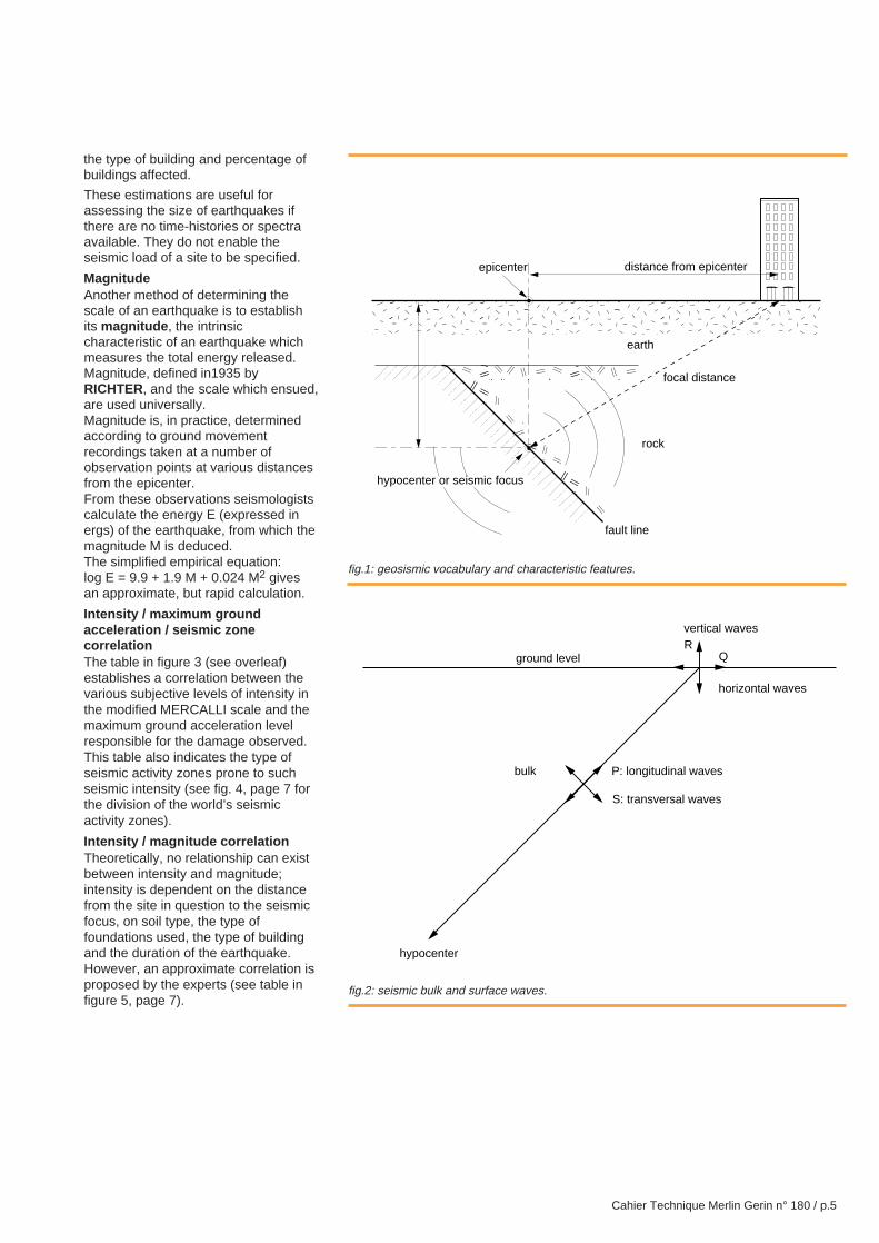
causes - locationThe majority of earthquakes occur onthe fault lines which demarcate thetectonic plates from the earth’s crust.Tension accumulates when the platesslowly shift away from each other. Thesudden release of distorting energywhich has thus accumulated inside theearth’s crust, or in the underlying layercalled the mantle, provokes a localagitation. Some of this energy is thentransformed into seismic waves at thesurface of the ground.It is the creation of a fault line, or morefrequently the slide along an existingfault line, which constitutes thegenerating mechanism of anearthquake. The place where it occursis called the seismic focus or thehypocenter and the projection fromthis point to the ground is called theepicenter (see fig. 1).The depth of the hypocenter variesgreatly: from a few kilometres to upto 100 km.
propagation of seismicwavesEarthquakes propagate in waveswhich, taking the heterogeneity of theground into account, provoke acomplex vibratory movement at thesurface which is difficult to predict for agiven site.
A distinction is made between twotypes of wave: bulk waves and surfacewaves.
Bulk wavesThey originate at the seismic focus andpropagate inside the earth’s mantle intwo different forms:c longitudinal waves characterised byalternating compressions and dilationswhich propagate at a speedof 7 to 8 km/s,c transversal waves characterised by aplane distortion perpendicular to the
direction of the propagation, whichprovoke shear and propagate at aspeed of 4 to 5 km/s (see fig. 2).
Remark:It is the difference in speed betweenthe longitudinal and transversal wavesand recordings taken from severalseismographs, which enables an earth-quake’s seismic focus to be located.
Surface wavesThese are generated by the bulk waveswhich reach the surface and propagateat a speed of 1.5 to 5 km/s.
A distinction is made between:c RAYLEIGH waves which cause theground points to describe ellipses in thevertical plane; they engendercompression and shear in the ground,c LOVE waves which cause the groundpoints to shift at a tangent to thesurface, perpendicular to thepropagation direction; they engendershear only (see fig. 2).
characteristics ofvibrations generated atground levelIn reality things are far more complex;the propagation of a seismic wave in aheterogeneous environment provokes acomplex system of refracted andreflected waves for each discontinuity,so that the seismic movement iscompletely random at ground level.
However, vibratory movements broughtabout at ground level by earthquakesdo produce common characteristics,and a certain number of parameters aregenerally employed to describe them.
Characteristics of random vibrationsprovoked at ground level by anearthquake:
c directionThe movement is made up ofsimultaneous independent vertical andhorizontal components;
c durationIt is usually between 15 and 30 s (anintense earthquake can last between60 and 120 seconds).
c frequencyBroad band random movementproduces preponderant energybetween 1 and 35 Hz, and provokesthe most destructive effects atbetween 1 and 10 Hz.
c level of accelerationThere is no correlation between thewaves observed in the two differentdirections: at any given moment theamplitudes and frequencies areindependent.
Horizontal ground acceleration isgenerally lower than 0.5 g(exceptionally higher than 1g,or 10 m/s2).Vertical acceleration has a loweramplitude. Observations show that therelationship between the maximumvertical and horizontal amplitudes is in
the order of 23
(for frequencies higher
than 3.5 Hz).
intensity and magnitudeIntensityThe scale of an earthquake is generallymeasured in terms of its intensity at theobservation site. This subjectiveevaluation is established in terms of theeffects felt by the population and thedamage incurred.
Different intensity scales have beendefined, which class the seismic effectsin order of increasing size, with the helpof some conventional descriptions:
c the MERCALLI scale describescommonly observed effects on theenvironment, buildings and man afteran earthquake,
c the MSK scale (or modified Mercalliscale), more precise than the original,includes an evaluation of the damage,
Cahier Technique Merlin Gerin n° 180 / p.5
fig.1: geosismic vocabulary and characteristic features.
fig.2: seismic bulk and surface waves.
the type of building and percentage ofbuildings affected.
These estimations are useful forassessing the size of earthquakes ifthere are no time-histories or spectraavailable. They do not enable theseismic load of a site to be specified.
MagnitudeAnother method of determining thescale of an earthquake is to establishits magnitude , the intrinsiccharacteristic of an earthquake whichmeasures the total energy released.Magnitude, defined in1935 byRICHTER, and the scale which ensued,are used universally.Magnitude is, in practice, determinedaccording to ground movementrecordings taken at a number ofobservation points at various distancesfrom the epicenter.From these observations seismologistscalculate the energy E (expressed inergs) of the earthquake, from which themagnitude M is deduced.The simplified empirical equation:log E = 9.9 + 1.9 M + 0.024 M2 givesan approximate, but rapid calculation.
Intensity / maximum groundacceleration / seismic zonecorrelationThe table in figure 3 (see overleaf)establishes a correlation between thevarious subjective levels of intensity inthe modified MERCALLI scale and themaximum ground acceleration levelresponsible for the damage observed.This table also indicates the type ofseismic activity zones prone to suchseismic intensity (see fig. 4, page 7 forthe division of the world’s seismicactivity zones).
Intensity / magnitude correlationTheoretically, no relationship can existbetween intensity and magnitude;intensity is dependent on the distancefrom the site in question to the seismicfocus, on soil type, the type offoundations used, the type of buildingand the duration of the earthquake.However, an approximate correlation isproposed by the experts (see table infigure 5, page 7).
�����������
������
���������
����
������
distance from epicenter
focal distance
rock
fault line
hypocenter or seismic focus
epicenter
earth
P: longitudinal wavesbulk
ground level
hypocenter
vertical waves
horizontal waves
R
S: transversal waves
Q
Cahier Technique Merlin Gerin n° 180 / p.6
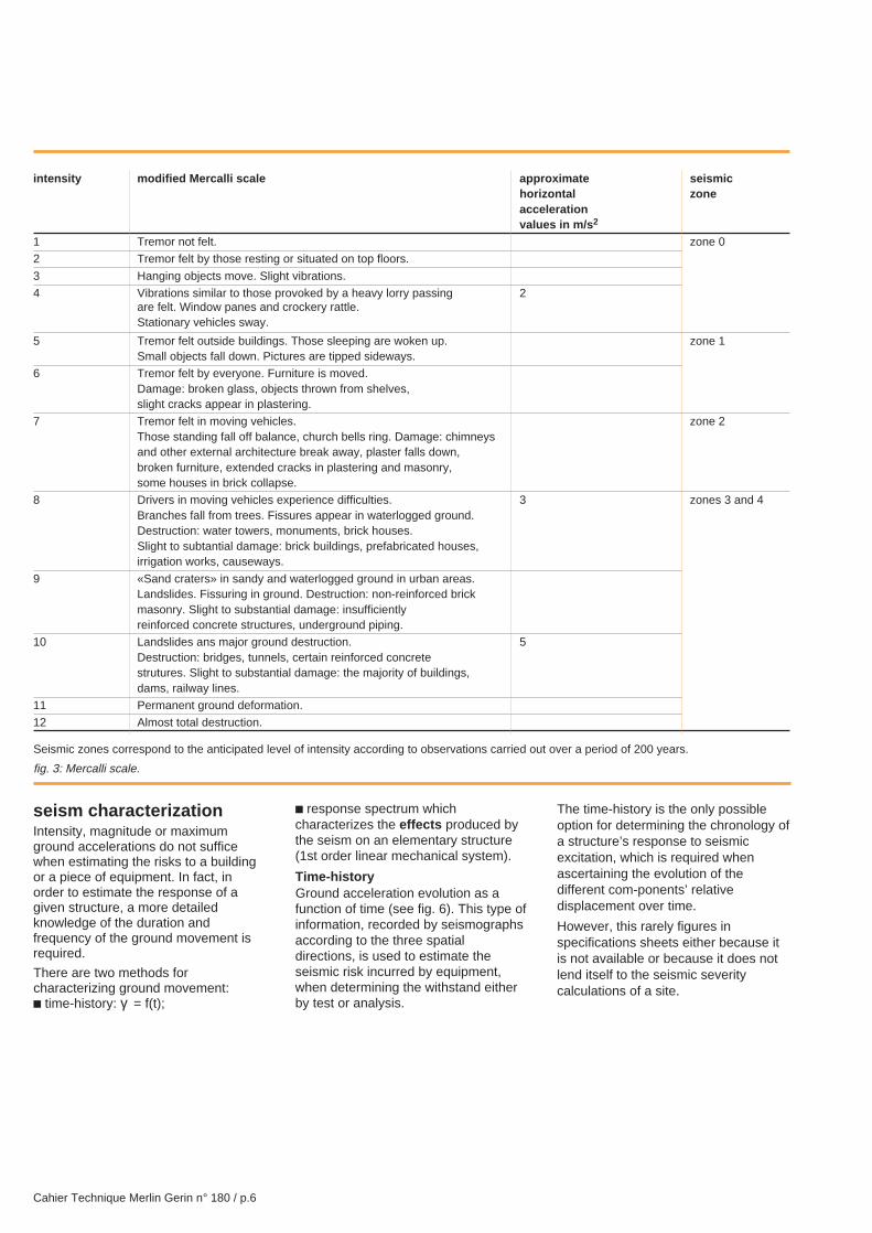
intensity modified Mercalli scale approximate seismichorizontal zoneaccelerationvalues in m/s 2
1 Tremor not felt. zone 0
2 Tremor felt by those resting or situated on top floors.
3 Hanging objects move. Slight vibrations.
4 Vibrations similar to those provoked by a heavy lorry passing 2are felt. Window panes and crockery rattle.Stationary vehicles sway.
5 Tremor felt outside buildings. Those sleeping are woken up. zone 1Small objects fall down. Pictures are tipped sideways.
6 Tremor felt by everyone. Furniture is moved.Damage: broken glass, objects thrown from shelves,slight cracks appear in plastering.
7 Tremor felt in moving vehicles. zone 2Those standing fall off balance, church bells ring. Damage: chimneysand other external architecture break away, plaster falls down,broken furniture, extended cracks in plastering and masonry,some houses in brick collapse.
8 Drivers in moving vehicles experience difficulties. 3 zones 3 and 4Branches fall from trees. Fissures appear in waterlogged ground.Destruction: water towers, monuments, brick houses.Slight to subtantial damage: brick buildings, prefabricated houses,irrigation works, causeways.
9 «Sand craters» in sandy and waterlogged ground in urban areas.Landslides. Fissuring in ground. Destruction: non-reinforced brickmasonry. Slight to substantial damage: insufficientlyreinforced concrete structures, underground piping.
10 Landslides ans major ground destruction. 5Destruction: bridges, tunnels, certain reinforced concretestrutures. Slight to substantial damage: the majority of buildings,dams, railway lines.
11 Permanent ground deformation.
12 Almost total destruction.
seism characterizationIntensity, magnitude or maximumground accelerations do not sufficewhen estimating the risks to a buildingor a piece of equipment. In fact, inorder to estimate the response of agiven structure, a more detailedknowledge of the duration andfrequency of the ground movement isrequired.
There are two methods forcharacterizing ground movement:c time-history: γ = f(t);
c response spectrum whichcharacterizes the effects produced bythe seism on an elementary structure(1st order linear mechanical system).
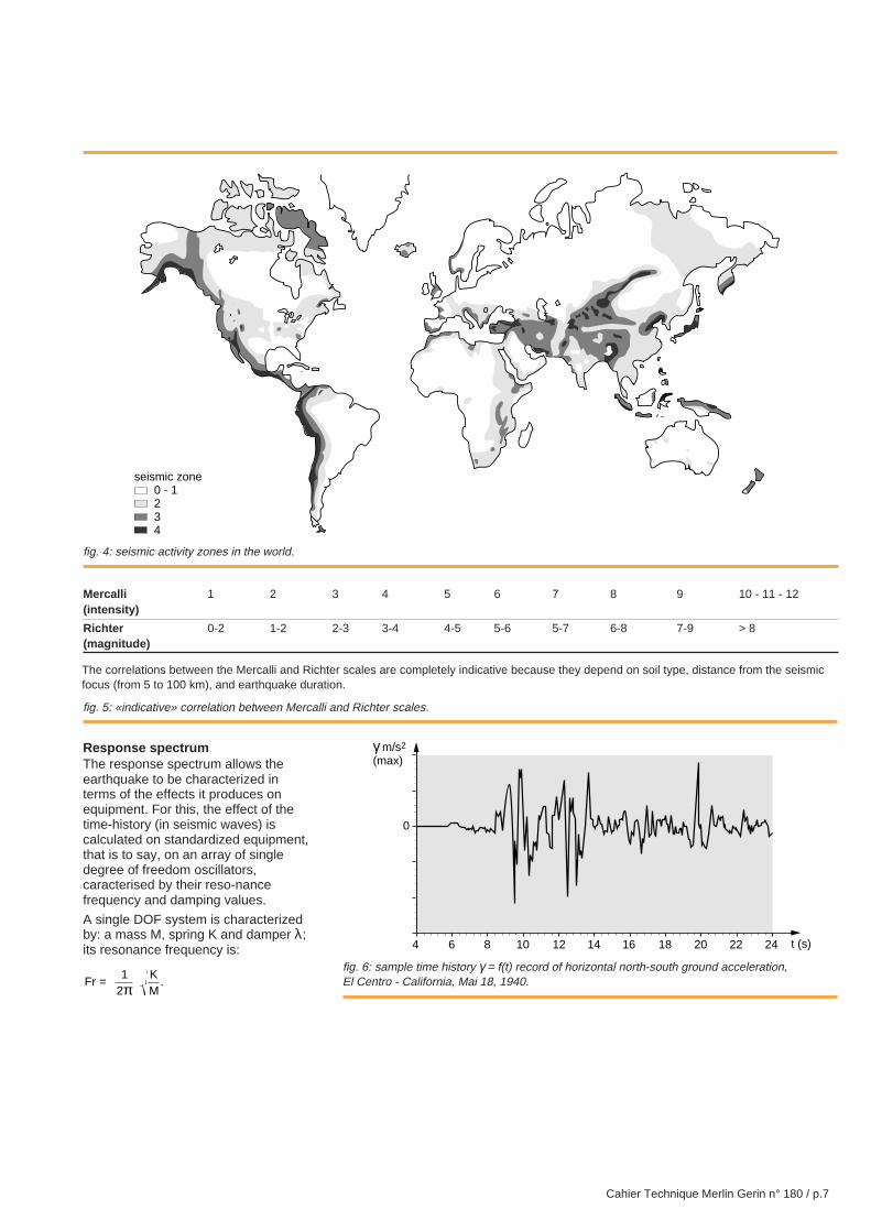
Time-historyGround acceleration evolution as afunction of time (see fig. 6). This type ofinformation, recorded by seismographsaccording to the three spatialdirections, is used to estimate theseismic risk incurred by equipment,when determining the withstand eitherby test or analysis.
The time-history is the only possibleoption for determining the chronology ofa structure’s response to seismicexcitation, which is required whenascertaining the evolution of thedifferent com-ponents’ relativedisplacement over time.
However, this rarely figures inspecifications sheets either because itis not available or because it does notlend itself to the seismic severitycalculations of a site.
fig. 3: Mercalli scale.
Seismic zones correspond to the anticipated level of intensity according to observations carried out over a period of 200 years.
Cahier Technique Merlin Gerin n° 180 / p.7
Mercalli 1 2 3 4 5 6 7 8 9 10 - 11 - 12(intensity)
Richter 0-2 1-2 2-3 3-4 4-5 5-6 5-7 6-8 7-9 > 8(magnitude)
fig. 4: seismic activity zones in the world.
fig. 5: «indicative» correlation between Mercalli and Richter scales.
The correlations between the Mercalli and Richter scales are completely indicative because they depend on soil type, distance from the seismicfocus (from 5 to 100 km), and earthquake duration.
Response spectrumThe response spectrum allows theearthquake to be characterized interms of the effects it produces onequipment. For this, the effect of thetime-history (in seismic waves) iscalculated on standardized equipment,that is to say, on an array of singledegree of freedom oscillators,caracterised by their reso-nancefrequency and damping values.
A single DOF system is characterizedby: a mass M, spring K and damper λ;its resonance frequency is:
FrKM
= .1
2π
fig. 6: sample time history γ = f(t) record of horizontal north-south ground acceleration,El Centro - California, Mai 18, 1940.
4
0
γ m/s2
(max)
6 8 10 12 14 16 18 20 22 24 t (s)
seismic zone0 - 1234
Cahier Technique Merlin Gerin n° 180 / p.8
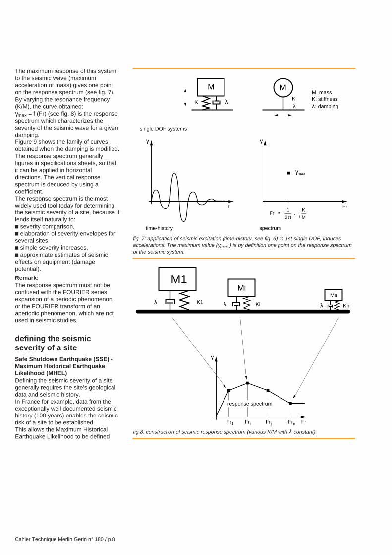
The maximum response of this systemto the seismic wave (maximumacceleration of mass) gives one pointon the response spectrum (see fig. 7).By varying the resonance frequency(K/M), the curve obtained:γmax = f (Fr) (see fig. 8) is the responsespectrum which characterizes theseverity of the seismic wave for a givendamping.Figure 9 shows the family of curvesobtained when the damping is modified.The response spectrum generallyfigures in specifications sheets, so thatit can be applied in horizontaldirections. The vertical responsespectrum is deduced by using acoefficient.The response spectrum is the mostwidely used tool today for determiningthe seismic severity of a site, because itlends itself naturally to:c severity comparison,c elaboration of severity envelopes forseveral sites,c simple severity increases,c approximate estimates of seismiceffects on equipment (damagepotential).
Remark:The response spectrum must not beconfused with the FOURIER seriesexpansion of a periodic phenomenon,or the FOURIER transform of anaperiodic phenomenon, which are notused in seismic studies.
defining the seismicseverity of a siteSafe Shutdown Earthquake (SSE) -Maximum Historical EarthquakeLikelihood (MHEL)Defining the seismic severity of a sitegenerally requires the site’s geologicaldata and seismic history.In France for example, data from theexceptionally well documented seismichistory (100 years) enables the seismicrisk of a site to be established.This allows the Maximum HistoricalEarthquake Likelihood to be defined
fig. 7: application of seismic excitation (time-history, see fig. 6) to 1st single DOF, inducesaccelerations. The maximum value (γmax ) is by definition one point on the response spectrumof the seismic system.
fig.8: construction of seismic response spectrum (various K/M with λ constant).
Fr = 1
2π .
K
M
M
γ
t
KKλλ
M
γ
Fr
γmax
single DOF systems
time-history spectrum
M: massK: stiffnessλ: damping
Mn
M1Mi
γ
Fr
response spectrum
Fr1 Fri Frj Frn
λ K1 λ Ki λ Kn
Cahier Technique Merlin Gerin n° 180 / p.9
which is likely to provoke the maximumeffect on a given site. For thedimensioning of works or equipment itis the SSE which is taken into account:the SSE is equivalent to the MHEL plusone degree on the MSK scale (modifiedMercalli scale).
Basic response spectrumMacro seismic data which correspondto the above definitions are notsufficient for the engineer who has todesign a building or an equipment. Hewill also require the representativeresponse spectrum of the siteconcerned, which is established byusing instrumental seismic data.
A seismotheque has been created(readings taken in regions ofconsiderable seismic activity), whichcorresponds to a scale of magnitudes,seismic focus depths and epicentraldistances for very diverse geologicalcontexts. This seismotheque allows theform of the response spectrum, or basicresponse spectrum as it is called, to beestablished, for a given region, with itsamplitude depending on the chosenSSE.This response spectrum definesseismic severity at ground level. Theseismic severity for the storey wherethe equipment will be installed still hasto be evaluated.
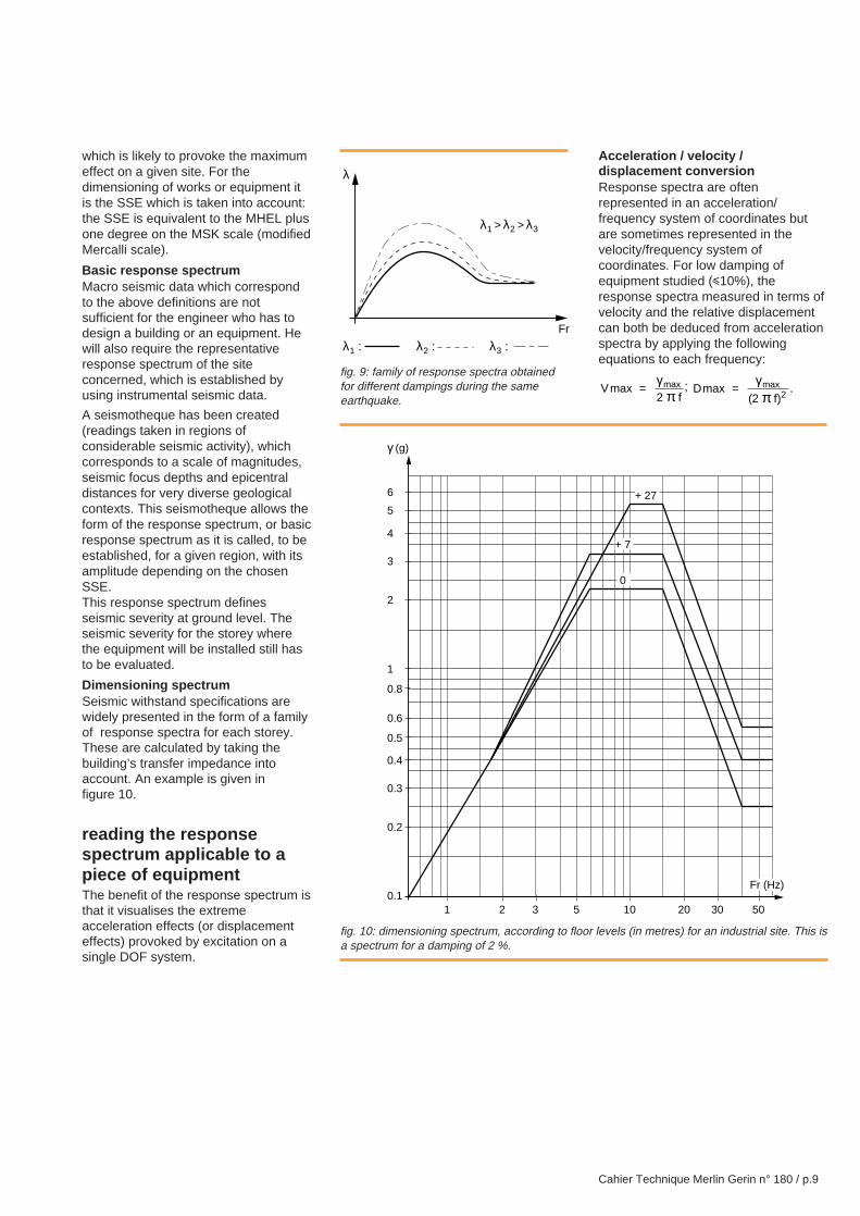
Dimensioning spectrumSeismic withstand specifications arewidely presented in the form of a familyof response spectra for each storey.These are calculated by taking thebuilding’s transfer impedance intoaccount. An example is given infigure 10.
reading the responsespectrum applicable to apiece of equipmentThe benefit of the response spectrum isthat it visualises the extremeacceleration effects (or displacementeffects) provoked by excitation on asingle DOF system.
Acceleration / velocity /displacement conversionResponse spectra are oftenrepresented in an acceleration/frequency system of coordinates butare sometimes represented in thevelocity/frequency system ofcoordinates. For low damping ofequipment studied (i10%), theresponse spectra measured in terms ofvelocity and the relative displacementcan both be deduced from accelerationspectra by applying the followingequations to each frequency:
Vf
max max=γ
π2; D
fmax
( ).max=
γπ2 2
fig. 9: family of response spectra obtainedfor different dampings during the sameearthquake.
fig. 10: dimensioning spectrum, according to floor levels (in metres) for an industrial site. This isa spectrum for a damping of 2 %.
0.11
0.2
0.3
0.4
0.5
0.6
0.8
1
γ (g)
2 3 5 10 20 30 50
2
3
4
5
6
Fr (Hz)
0
+ 7
+ 27
λ
Fr
λ1 : λ2 : λ3 :
λ1 > λ2 > λ3
Cahier Technique Merlin Gerin n° 180 / p.10
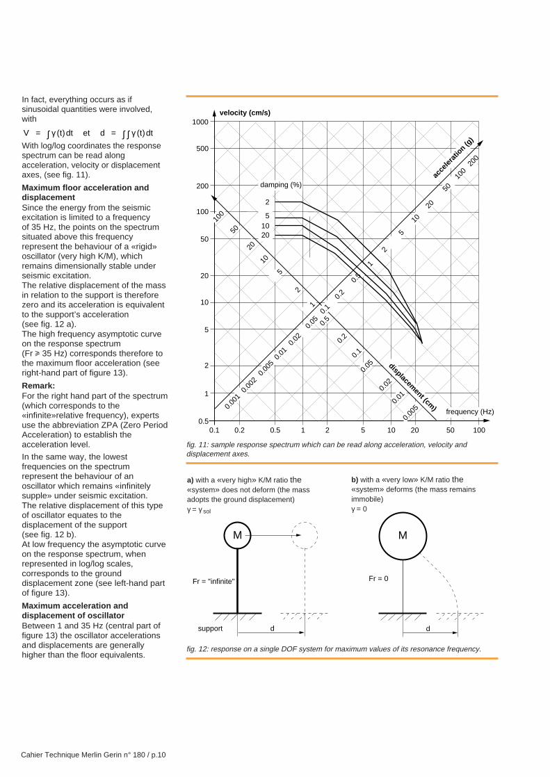
In fact, everything occurs as ifsinusoidal quantities were involved,with
V t dt et d t dt ( ) ( )= =∫ ∫∫γ γWith log/log coordinates the responsespectrum can be read alongacceleration, velocity or displacementaxes, (see fig. 11).
Maximum floor acceleration anddisplacementSince the energy from the seismicexcitation is limited to a frequencyof 35 Hz, the points on the spectrumsituated above this frequencyrepresent the behaviour of a «rigid»oscillator (very high K/M), whichremains dimensionally stable underseismic excitation.The relative displacement of the massin relation to the support is thereforezero and its acceleration is equivalentto the support’s acceleration(see fig. 12 a).The high frequency asymptotic curveon the response spectrum(Fr u 35 Hz) corresponds therefore tothe maximum floor acceleration (seeright-hand part of figure 13).
Remark:For the right hand part of the spectrum(which corresponds to the«infinite»relative frequency), expertsuse the abbreviation ZPA (Zero PeriodAcceleration) to establish theacceleration level.
In the same way, the lowestfrequencies on the spectrumrepresent the behaviour of anoscillator which remains «infinitelysupple» under seismic excitation.The relative displacement of this typeof oscillator equates to thedisplacement of the support(see fig. 12 b).At low frequency the asymptotic curveon the response spectrum, whenrepresented in log/log scales,corresponds to the grounddisplacement zone (see left-hand partof figure 13).
Maximum acceleration anddisplacement of oscillatorBetween 1 and 35 Hz (central part offigure 13) the oscillator accelerationsand displacements are generallyhigher than the floor equivalents.
fig. 11: sample response spectrum which can be read along acceleration, velocity anddisplacement axes.
fig. 12: response on a single DOF system for maximum values of its resonance frequency.
a) with a «very high» K/M ratio the«system» does not deform (the massadopts the ground displacement)γ = γ sol
b) with a «very low» K/M ratio the«system» deforms (the mass remainsimmobile)γ = 0
0.1
1000
500
100
50
20
10
5
2
1
0.5
0.2
0.1
0.05
0.02
0.01
200
100
50
20
10
5
2
1
0.5
velocity (cm/s)
0.2 0.5 1 2 5 10 20 50 100
frequency (Hz)
displacement (cm
)0.00
10.
002
0.00
50.
010.
020.
050.
10.
2
0.5
1
2
5
10
20
5010
020
0
acce
lerat
ion (g
)
0.00
5
damping (%)
2
51020
M
d
Fr = "infinite"
support
M
d
Fr = 0
Cahier Technique Merlin Gerin n° 180 / p.11
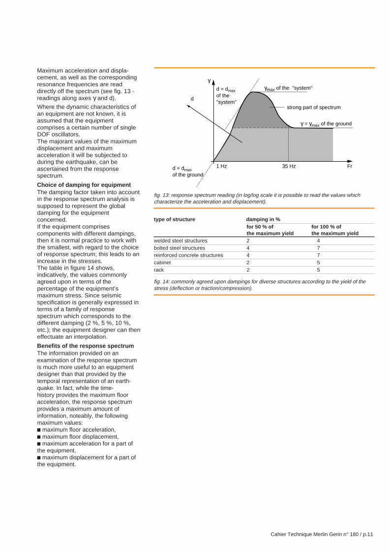
Maximum acceleration and displa-cement, as well as the correspondingresonance frequencies are readdirectly off the spectrum (see fig. 13 -readings along axes γ and d).
Where the dynamic characteristics ofan equipment are not known, it isassumed that the equipmentcomprises a certain number of singleDOF oscillators.The majorant values of the maximumdisplacement and maximumacceleration it will be subjected toduring the earthquake, can beascertained from the responsespectrum.
Choice of damping for equipmentThe damping factor taken into accountin the response spectrum analysis issupposed to represent the globaldamping for the equipmentconcerned.If the equipment comprisescomponents with different dampings,then it is normal practice to work withthe smallest, with regard to the choiceof response spectrum; this leads to anincrease in the stresses.The table in figure 14 shows,indicatively, the values commonlyagreed upon in terms of thepercentage of the equipment’smaximum stress. Since seismicspecification is generally expressed interms of a family of responsespectrum which corresponds to thedifferent damping (2 %, 5 %, 10 %,etc.); the equipment designer can theneffectuate an interpolation.
Benefits of the response spectrumThe information provided on anexamination of the response spectrumis much more useful to an equipmentdesigner than that provided by thetemporal representation of an earth-quake. In fact, while the time-history provides the maximum flooracceleration, the response spectrumprovides a maximum amount ofinformation, noteably, the followingmaximum values:c maximum floor acceleration,c maximum floor displacement,c maximum acceleration for a part ofthe equipment,c maximum displacement for a part ofthe equipment.
fig. 13: response spectrum reading (in log/log scale it is possible to read the values whichcharacterize the acceleration and displacement).
type of structure damping in %for 50 % of for 100 % ofthe maximum yield the maximum yield
welded steel structures 2 4bolted steel structures 4 7reinforced concrete structures 4 7cabinet 2 5rack 2 5
fig. 14: commonly agreed upon dampings for diverse structures according to the yield of thestress (deflection or traction/compression).
γ
Fr35 Hz1 Hz
γmax of the "system"
γ = γmax of the ground
d = dmaxof the"system"
d = dmaxof the ground
d
strong part of spectrum
Cahier Technique Merlin Gerin n° 180 / p.12
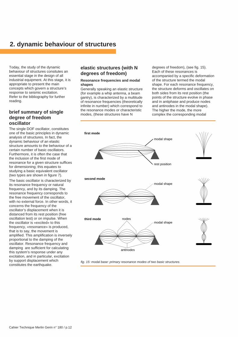
elastic structures (with Ndegrees of freedom)Resonance frequencies and modalshapesGenerally speaking an elastic structure(for example a whip antenna, a beamgantry), is characterized by a multitudeof resonance frequencies (theoreticallyinfinite in number) which correspond tothe resonance modes or characteristicmodes, (these structures have N
degrees of freedom), (see fig. 15).Each of these resonances isaccompanied by a specific deformationof the structure termed the modalshape. For each resonance frequency,the structure deforms and oscillates onboth sides from its rest position (thepoints of the structure evolve in phaseand in antiphase and produce nodesand antinodes in the modal shape).The higher the mode, the morecomplex the corresponding modal
2. dynamic behaviour of structures
Today, the study of the dynamicbehaviour of structures consitutes anessential stage in the design of allindustrial equipment. At this stage, it isappropriate to present the mainconcepts which govern a structure’sresponse to seismic excitation.Refer to the bibliography for furtherreading.
brief summary of singledegree of freedomoscillatorThe single DOF oscillator, constitutesone of the basic principles in dynamicanalysis of structures. In fact, thedynamic behaviour of an elasticstructure amounts to the behaviour of acertain number of basic oscillators.Furthermore, it is often the case thatthe inclusion of the first mode ofresonance for a given structure sufficesfor dimensioning; this equates tostudying a basic equivalent oscillator(two types are shown in figure 7).
The basic oscillator is characterized byits resonance frequency or naturalfrequency, and by its damping. Theresonance frequency corresponds tothe free movement of the oscillator,with no external force. In other words, itconcerns the frequency of theoscillator’s displacement when it isdistanced from its rest position (freeoscillation test) or on impulse. Whenthe oscillator is «excited» to thisfrequency, «resonance» is produced,that is to say, the movement isamplified. This amplification is inverselyproportional to the damping of theoscillator. Resonance frequency anddamping are sufficient for calculatingthis system’s response under anyexcitation, and in particular, excitationby support displacement whichconstitutes the earthquake.
fig. 15: modal base: primary resonance modes of two basic structures.
first mode
second mode
third mode
modal shape
rest position
modal shape
modal shapenodes
antinodes
Cahier Technique Merlin Gerin n° 180 / p.13
shape becomes, with an increasingnumber of nodes and antinodes.The dynamic behaviour of structures,comprising N basic structures with onedegree of freedom, (see fig. 16), isusually determined by using what isknown as the modal analysis of thestucture, which consists of tracing theresonance frequencies and modalshapes on the frequency band thatcorresponds to the earthquake. Thisestablishes a work basis comprising thestructure’s N primary modes, called themodal base, in which the initial problemwill be reduced to the study andcombination of N single DOF systems(see fig. 16 right).
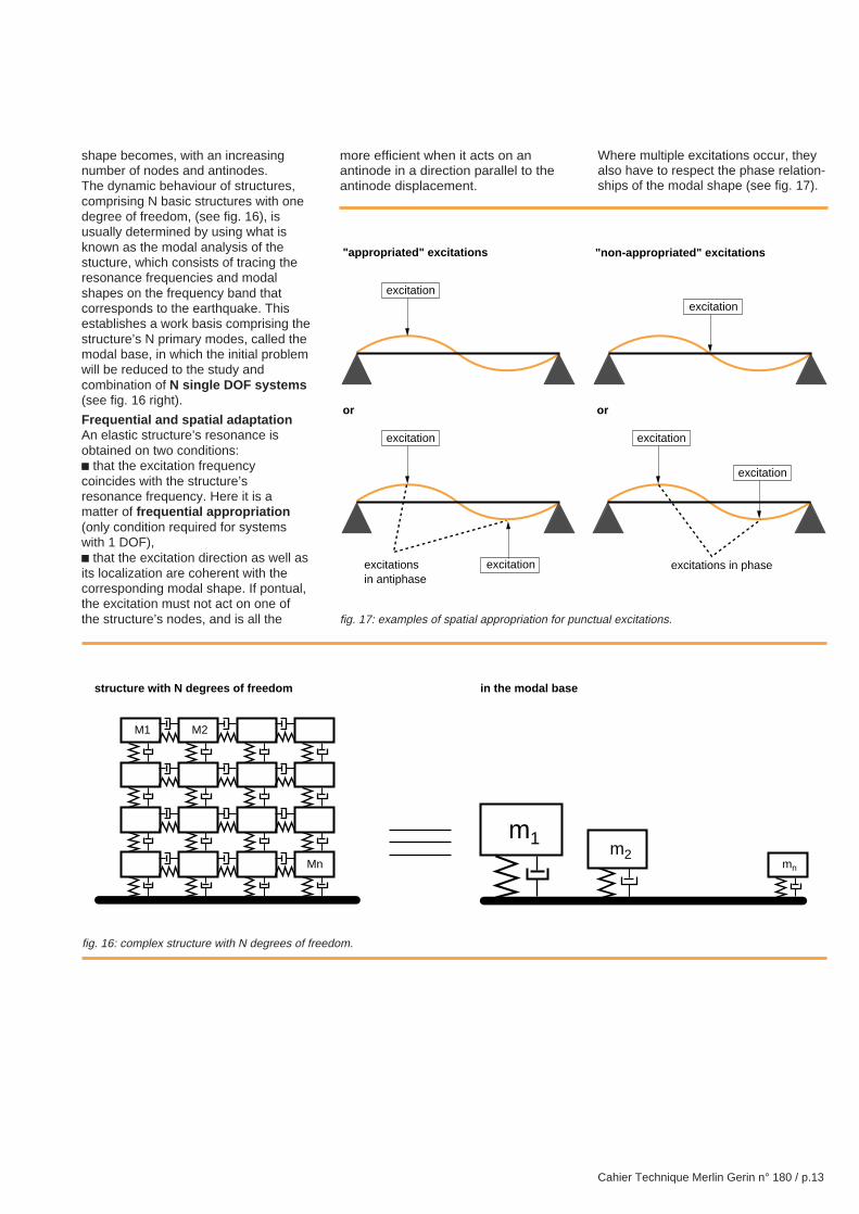
Frequential and spatial adaptationAn elastic structure’s resonance isobtained on two conditions:c that the excitation frequencycoincides with the structure’sresonance frequency. Here it is amatter of frequential appropriation(only condition required for systemswith 1 DOF),c that the excitation direction as well asits localization are coherent with thecorresponding modal shape. If pontual,the excitation must not act on one ofthe structure’s nodes, and is all the
more efficient when it acts on anantinode in a direction parallel to theantinode displacement.
Where multiple excitations occur, theyalso have to respect the phase relation-ships of the modal shape (see fig. 17).
fig. 16: complex structure with N degrees of freedom.
fig. 17: examples of spatial appropriation for punctual excitations.
excitationsin antiphase
excitations in phaseexcitation
or or
"appropriated" excitations "non-appropriated" excitations
excitation
excitation
excitation
excitation
excitation
structure with N degrees of freedom in the modal base
Mn
M1 M2
mn
m1m2
Cahier Technique Merlin Gerin n° 180 / p.14
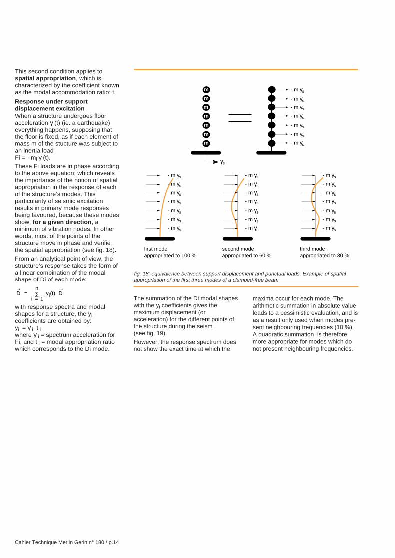
This second condition applies tospatial appropriation , which ischaracterized by the coefficient knownas the modal accommodation ratio: t.
Response under supportdisplacement excitationWhen a structure undergoes flooracceleration γ (t) (ie. a earthquake)everything happens, supposing thatthe floor is fixed, as if each element ofmass m of the stucture was subject toan inertia loadFi = - mi γ (t).These Fi loads are in phase accordingto the above equation; which revealsthe importance of the notion of spatialappropriation in the response of eachof the structure’s modes. Thisparticularity of seismic excitationresults in primary mode responsesbeing favoured, because these modesshow, for a given direction , aminimum of vibration nodes. In otherwords, most of the points of thestructure move in phase and verifiethe spatial appropriation (see fig. 18).
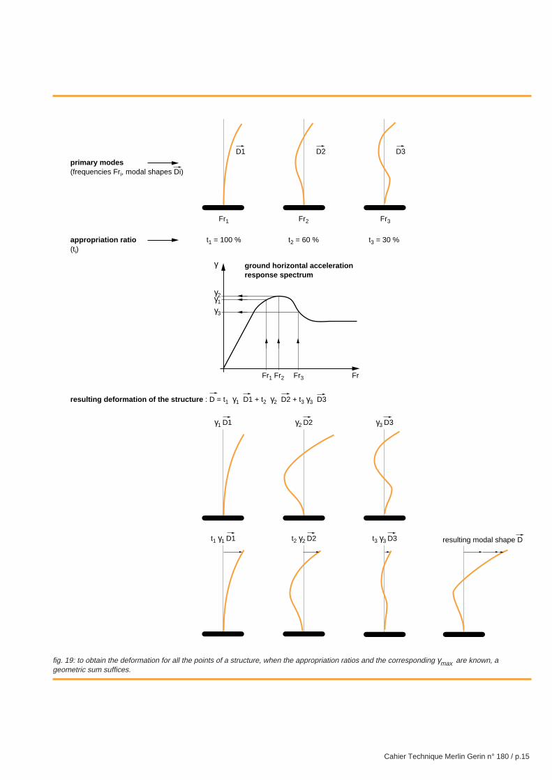
From an analytical point of view, thestructure’s response takes the form ofa linear combination of the modalshape of Di of each mode:
Di
nyi t Di
→=
=∑
→
( )
1
with response spectra and modalshapes for a structure, the yicoefficients are obtained by:yi = γ i t iwhere γ i = spectrum acceleration forFi, and t i = modal appropriation ratiowhich corresponds to the Di mode.
fig. 18: equivalence between support displacement and punctual loads. Example of spatialappropriation of the first three modes of a clamped-free beam.
The summation of the Di modal shapeswith the yi coefficients gives themaximum displacement (oracceleration) for the different points ofthe structure during the seism(see fig. 19).
However, the response spectrum doesnot show the exact time at which the
maxima occur for each mode. Thearithmetic summation in absolute valueleads to a pessimistic evaluation, and isas a result only used when modes pre-sent neighbouring frequencies (10 %).A quadratic summation is thereforemore appropriate for modes which donot present neighbouring frequencies.
m
m
m
m
m
m
m
γs
first modeappropriated to 100 %
second mode appropriated to 60 %
third mode appropriated to 30 %
- m γs
- m γs
- m γs
- m γs
- m γs
- m γs
- m γs
- m γs
- m γs
- m γs
- m γs
- m γs
- m γs
- m γs
- m γs
- m γs
- m γs
- m γs
- m γs
- m γs
- m γs
- m γs
- m γs
- m γs
- m γs
- m γs
- m γs
- m γs
Cahier Technique Merlin Gerin n° 180 / p.15
fig. 19: to obtain the deformation for all the points of a structure, when the appropriation ratios and the corresponding γmax are known, ageometric sum suffices.
t1 = 100 % t2 = 60 % t3 = 30 %
D1
Fr1
D2
Fr2
D3
Fr3
γ3 D3γ2 D2γ1 D1
t1 γ1 D1
primary modes(frequencies Fri, modal shapes Di)
appropriation ratio(ti)
resulting deformation of the structure : D = t1 γ1 D1 + t2 γ2 D2 + t3 γ3 D3
γ
FrFr3Fr2Fr1
γ1
γ2
γ3
ground horizontal accelerationresponse spectrum
t2 γ2 D2 t3 γ3 D3 resulting modal shape D
Cahier Technique Merlin Gerin n° 180 / p.16
3. equipment design
(level of acceleration at which theequipment no longer performs itsfunction) has to be determinedbeforehand.
Functional withstand capabilityThe vibratory stresses to which thefunctional devices will be subjectedmust be evaluated, and there must beassurance that they would functioncorrectly when put under thesestresses, or that their availability isunaffected.
There are two possibilities:c the functional device is a protectiveor monitoring device produced inseries: the equipment generallyundergoes a vibratory environmentqualification, the results of which canbe exploited in order for the seismicwithstand capabilities to be evaluated.Otherwise, the equipment’s behaviouron the seismic excitation range(0-40 Hz) must be studied,c the functional device is a specialdevice, in which case an evaluation bytest is necessary.
In certain cases, an analysis of thetests carried out on an analogousequipment, can provide the technicalelements which will reveal thefunctional withstand capabilities of anapparatus.
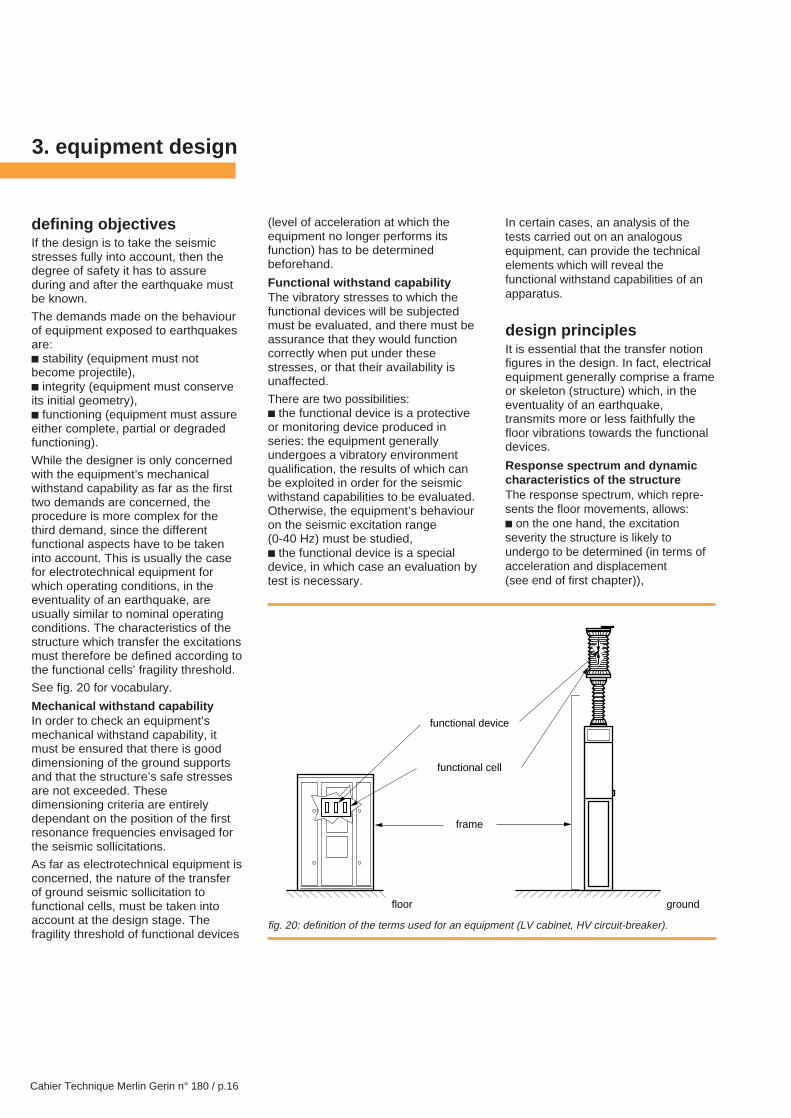
design principlesIt is essential that the transfer notionfigures in the design. In fact, electricalequipment generally comprise a frameor skeleton (structure) which, in theeventuality of an earthquake,transmits more or less faithfully thefloor vibrations towards the functionaldevices.
Respo nse spectrum and dynamiccharacteristics of the structureThe response spectrum, which repre-sents the floor movements, allows:c on the one hand, the excitationseverity the structure is likely toundergo to be determined (in terms ofacceleration and displacement(see end of first chapter)),
defining objectivesIf the design is to take the seismicstresses fully into account, then thedegree of safety it has to assureduring and after the earthquake mustbe known.
The demands made on the behaviourof equipment exposed to earthquakesare:c stability (equipment must notbecome projectile),c integrity (equipment must conserveits initial geometry),c functioning (equipment must assureeither complete, partial or degradedfunctioning).
While the designer is only concernedwith the equipment’s mechanicalwithstand capability as far as the firsttwo demands are concerned, theprocedure is more complex for thethird demand, since the differentfunctional aspects have to be takeninto account. This is usually the casefor electrotechnical equipment forwhich operating conditions, in theeventuality of an earthquake, areusually similar to nominal operatingconditions. The characteristics of thestructure which transfer the excitationsmust therefore be defined according tothe functional cells’ fragility threshold.
See fig. 20 for vocabulary.
Mechanical withstand capabilityIn order to check an equipment’smechanical withstand capability, itmust be ensured that there is gooddimensioning of the ground supportsand that the structure’s safe stressesare not exceeded. Thesedimensioning criteria are entirelydependant on the position of the firstresonance frequencies envisaged forthe seismic sollicitations.
As far as electrotechnical equipment isconcerned, the nature of the transferof ground seismic sollicitation tofunctional cells, must be taken intoaccount at the design stage. Thefragility threshold of functional devices
fig. 20: definition of the terms used for an equipment (LV cabinet, HV circuit-breaker).
functional device
functional cell
frame
groundfloor
Cahier Technique Merlin Gerin n° 180 / p.17
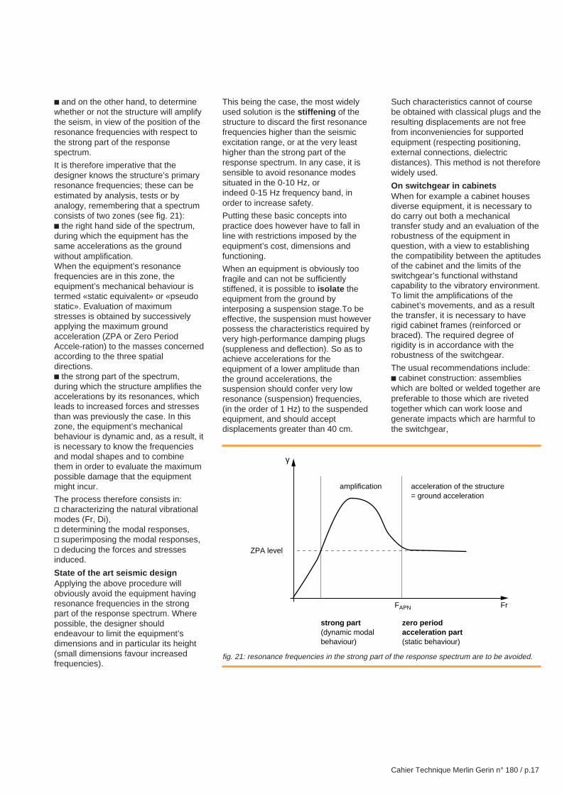
c and on the other hand, to determinewhether or not the structure will amplifythe seism, in view of the position of theresonance frequencies with respect tothe strong part of the responsespectrum.
It is therefore imperative that thedesigner knows the structure’s primaryresonance frequencies; these can beestimated by analysis, tests or byanalogy, remembering that a spectrumconsists of two zones (see fig. 21):c the right hand side of the spectrum,during which the equipment has thesame accelerations as the groundwithout amplification.When the equipment’s resonancefrequencies are in this zone, theequipment’s mechanical behaviour istermed «static equivalent» or «pseudostatic». Evaluation of maximumstresses is obtained by successivelyapplying the maximum groundacceleration (ZPA or Zero PeriodAccele-ration) to the masses concernedaccording to the three spatialdirections.c the strong part of the spectrum,during which the structure amplifies theaccelerations by its resonances, whichleads to increased forces and stressesthan was previously the case. In thiszone, the equipment’s mechanicalbehaviour is dynamic and, as a result, itis necessary to know the frequenciesand modal shapes and to combinethem in order to evaluate the maximumpossible damage that the equipmentmight incur.
The process therefore consists in:v characterizing the natural vibrationalmodes (Fr, Di),v determining the modal responses,v superimposing the modal responses,v deducing the forces and stressesinduced.
State of the art seismic designApplying the above procedure willobviously avoid the equipment havingresonance frequencies in the strongpart of the response spectrum. Wherepossible, the designer shouldendeavour to limit the equipment’sdimensions and in particular its height(small dimensions favour increasedfrequencies).
This being the case, the most widelyused solution is the stiffening of thestructure to discard the first resonancefrequencies higher than the seismicexcitation range, or at the very leasthigher than the strong part of theresponse spectrum. In any case, it issensible to avoid resonance modessituated in the 0-10 Hz, orindeed 0-15 Hz frequency band, inorder to increase safety.
Putting these basic concepts intopractice does however have to fall inline with restrictions imposed by theequipment’s cost, dimensions andfunctioning.
When an equipment is obviously toofragile and can not be sufficientlystiffened, it is possible to isolate theequipment from the ground byinterposing a suspension stage.To beeffective, the suspension must howeverpossess the characteristics required byvery high-performance damping plugs(suppleness and deflection). So as toachieve accelerations for theequipment of a lower amplitude thanthe ground accelerations, thesuspension should confer very lowresonance (suspension) frequencies,(in the order of 1 Hz) to the suspendedequipment, and should acceptdisplacements greater than 40 cm.
Such characteristics cannot of coursebe obtained with classical plugs and theresulting displacements are not freefrom inconveniencies for supportedequipment (respecting positioning,external connections, dielectricdistances). This method is not thereforewidely used.
On switchgear in cabinetsWhen for example a cabinet housesdiverse equipment, it is necessary todo carry out both a mechanicaltransfer study and an evaluation of therobustness of the equipment inquestion, with a view to establishingthe compatibility between the aptitudesof the cabinet and the limits of theswitchgear’s functional withstandcapability to the vibratory environment.To limit the amplifications of thecabinet’s movements, and as a resultthe transfer, it is necessary to haverigid cabinet frames (reinforced orbraced). The required degree ofrigidity is in accordance with therobustness of the switchgear.
The usual recommendations include:c cabinet construction: assemblieswhich are bolted or welded together arepreferable to those which are rivetedtogether which can work loose andgenerate impacts which are harmful tothe switchgear,
fig. 21: resonance frequencies in the strong part of the response spectrum are to be avoided.
γ
FrFAPN
amplification
strong part(dynamic modalbehaviour)
zero periodacceleration part(static behaviour)
acceleration of the structure= ground acceleration
ZPA level
Cahier Technique Merlin Gerin n° 180 / p.18
c mounting of the cabinet: the idealsolution consists in bolting the cabinetto the ground and the wall, with fixingswhich must be dimensioned so as toresist the loads resulting from seismicacceleration,c disposition of the cabinet: if thecabinet is only mounted to the ground,it is better for the heavy masses to bearranged at the bottom of the cabinet;the same applies to fragile devices,c mounting of devices: rigid fixings arepreferable; otherwise, it is wise to bewary of local resonance modes, and tothe different movements during theseism,c circuit boards: avoid boards whichare too large or too full, heavy compo-nents; provide stiffeners if necessary,c cabling: so as to avoid inertia loads,flange the cable layer as close aspossible to the connectors.
simulation by analysis atdesign stageNumerical analysis for a structure’sdynamic behaviour generally uses thefinite elements method. This numericaltechnique allows the mechanicalbehaviour of a structure, subjected todynamic sollicitations, similar to thosegenerated by an earthquake, to bepredicted. This technique is particularlywell suited to the design stage, whenthe structure only exists in the form ofdefinition or utilisation plan, and can stillbe modified. It provides essential datafor the designers with regard tostresses, anchorage loads and thedeformations produced by the seismicexcitation.
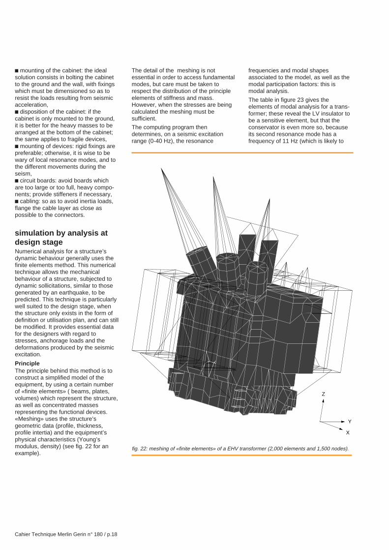
PrincipleThe principle behind this method is toconstruct a simplified model of theequipment, by using a certain numberof «finite elements» ( beams, plates,volumes) which represent the structure,as well as concentrated massesrepresenting the functional devices.«Meshing» uses the structure’sgeometric data (profile, thickness,profile intertia) and the equipment’sphysical characteristics (Young’smodulus, density) (see fig. 22 for anexample).
The detail of the meshing is notessential in order to access fundamentalmodes, but care must be taken torespect the distribution of the principleelements of stiffness and mass.However, when the stresses are beingcalculated the meshing must besufficient.
The computing program thendetermines, on a seismic excitationrange (0-40 Hz), the resonance
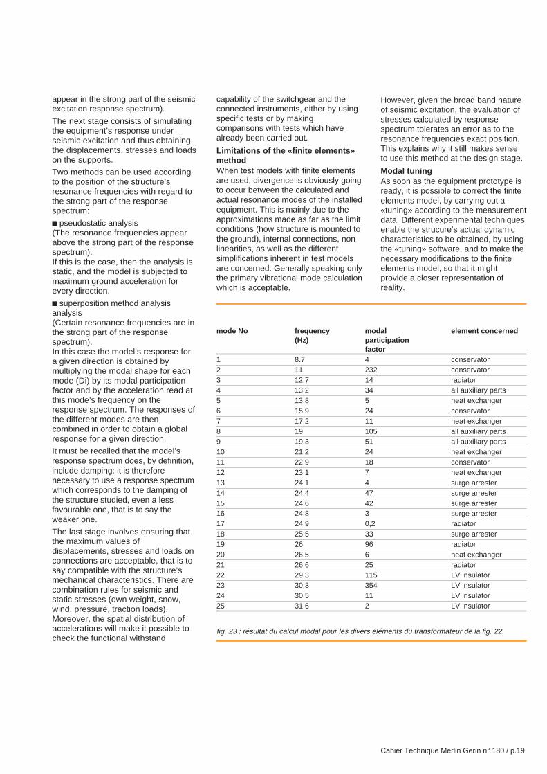
frequencies and modal shapesassociated to the model, as well as themodal participation factors: this ismodal analysis.
The table in figure 23 gives theelements of modal analysis for a trans-former; these reveal the LV insulator tobe a sensitive element, but that theconservator is even more so, becauseits second resonance mode has afrequency of 11 Hz (which is likely to
fig. 22: meshing of «finite elements» of a EHV transformer (2,000 elements and 1,500 nodes).
X
Y
Z
Cahier Technique Merlin Gerin n° 180 / p.19
appear in the strong part of the seismicexcitation response spectrum).
The next stage consists of simulatingthe equipment’s response underseismic excitation and thus obtainingthe displacements, stresses and loadson the supports.
Two methods can be used accordingto the position of the structure’sresonance frequencies with regard tothe strong part of the responsespectrum:
c pseudostatic analysis(The resonance frequencies appearabove the strong part of the responsespectrum).If this is the case, then the analysis isstatic, and the model is subjected tomaximum ground acceleration forevery direction.
c superposition method analysisanalysis(Certain resonance frequencies are inthe strong part of the responsespectrum).In this case the model’s response fora given direction is obtained bymultiplying the modal shape for eachmode (Di) by its modal participationfactor and by the acceleration read atthis mode’s frequency on theresponse spectrum. The responses ofthe different modes are thencombined in order to obtain a globalresponse for a given direction.
It must be recalled that the model’sresponse spectrum does, by definition,include damping: it is thereforenecessary to use a response spectrumwhich corresponds to the damping ofthe structure studied, even a lessfavourable one, that is to say theweaker one.
The last stage involves ensuring thatthe maximum values ofdisplacements, stresses and loads onconnections are acceptable, that is tosay compatible with the structure’smechanical characteristics. There arecombination rules for seismic andstatic stresses (own weight, snow,wind, pressure, traction loads).Moreover, the spatial distribution ofaccelerations will make it possible tocheck the functional withstand
capability of the switchgear and theconnected instruments, either by usingspecific tests or by makingcomparisons with tests which havealready been carried out.
Limitations of the «finite elements»methodWhen test models with finite elementsare used, divergence is obviously goingto occur between the calculated andactual resonance modes of the installedequipment. This is mainly due to theapproximations made as far as the limitconditions (how structure is mounted tothe ground), internal connections, nonlinearities, as well as the differentsimplifications inherent in test modelsare concerned. Generally speaking onlythe primary vibrational mode calculationwhich is acceptable.
However, given the broad band natureof seismic excitation, the evaluation ofstresses calculated by responsespectrum tolerates an error as to theresonance frequencies exact position.This explains why it still makes senseto use this method at the design stage.
Modal tuningAs soon as the equipment prototype isready, it is possible to correct the finiteelements model, by carrying out a«tuning» according to the measurementdata. Different experimental techniquesenable the strucure’s actual dynamiccharacteristics to be obtained, by usingthe «tuning» software, and to make thenecessary modifications to the finiteelements model, so that it mightprovide a closer representation ofreality.
fig. 23 : résultat du calcul modal pour les divers éléments du transformateur de la fig. 22.
mode No frequency modal element concerned(Hz) participation
factor1 8.7 4 conservator2 11 232 conservator3 12.7 14 radiator4 13.2 34 all auxiliary parts5 13.8 5 heat exchanger6 15.9 24 conservator7 17.2 11 heat exchanger8 19 105 all auxiliary parts9 19.3 51 all auxiliary parts10 21.2 24 heat exchanger11 22.9 18 conservator12 23.1 7 heat exchanger13 24.1 4 surge arrester14 24.4 47 surge arrester15 24.6 42 surge arrester16 24.8 3 surge arrester17 24.9 0,2 radiator18 25.5 33 surge arrester19 26 96 radiator20 26.5 6 heat exchanger21 26.6 25 radiator22 29.3 115 LV insulator23 30.3 354 LV insulator24 30.5 11 LV insulator25 31.6 2 LV insulator

Cahier Technique Merlin Gerin n° 180 / p.20
4. qualification by simulation or test
c second stage: experimental modalanalysis (see fig. 25 and 26).This analysis is carried out on theprototype. It consists in acquiring thetransfer functions between a point ofexcitation (generated force) and theresponse points (measuredaccelerations), then identifying theactual modes of the structure(resonance frequencies and associatedmodal shapes),
c third stage: tuning of finite elementmodel.Here the parameters of the finiteelement model are readjusted (finenessof meshing, physical parameters:YOUNG’s modulus, density, limitconditions) so that the model’s dynamiccharacteristics can be made to reflectreality as closely as possible,
c fourth stage: measuring the dampingcoefficient.
introductionTo qualify means proving theequipment’s withstand capability underidentified or normalized stresses.There are two ways of realizing seismicqualification:c the first involves effectuating «realsize» tests on the equipment;c the second uses «finite element» testmodels which can be combined with acertain amount of experimental data.The latter is becoming more and moreimportant in the qualification process,particularly as far as mechanicalwithstand capability is concerned. Buttoday it is still tricky to take account ofthe functional aspect by using a testmodel.
Qualification by test is used:c for equipment with dimensions whichlend themselves to the vibration testingmachine,c for specific equipment (unitary, smallseries),c if the functional aspect is determining(complex or high level of safety).
Qualification by numerical analysisis used if:c the dimensions of the equipment areincompatible with the testing machines(as is the case for large transformers),c a device has already been testedunder other seismic conditions,c the device is a modified version of aqualified device,c the functioning of the equipment isnot requisite during the earthquake.
Combined qualification by numericalanalysis and experimental modaltuning is used:c for large series equipment,c when standards or operators permitthis kind of justification (knowledge offunctional data).
In fact, numerical analysis oftenprecede «real size» tests. Thismaximizes chances of correctly
effectuating the qualification testssuccessfully first time round.
We will now:c illustrate by means of two examples:combined qualification and qualificationby «real size» tests preceded by adesign test model,c develop the methodology ofqualification by test.
combined qualification(numerical analysis andexperimental tuning)The method which combines bothanalysis and tests involves:c creating a mathematical model,c gathering in the data from partialtests (modal experimental analysis)carried out on the prototype,concerning the device’s dynamicbehaviour (damping, resonancefrequencies, modal shapes),c tuning the mathematical model withthe preceding data.
The analysis model then allows themechanical withstand capability to beevaluated under accumulated seismicsollicitations and service stresses. Thefunctional withstand capability involveschecking that the equipment is notbadly affected by the deformations andaccelerations delivered by the analysis.
The following example shows themethod which combines both tests andcalculation used to define seismicresistance of HV circuit-breaker.
Seismic qualification of a HV circuit-breaker(see fig. 24)c first stage: numerical analysis ofcircuit-breaker.The model is made out of finiteelements: (beam-gantries, plates andshells for the insulators), the modelcomprises 2,670 elementsand 3,200 nodes,
fig. 24: Merlin Gerin circuit-breaker designedfor use in HV switchgear equipment.

Cahier Technique Merlin Gerin n° 180 / p.21
In order to calculate the circuit-breaker’s response using theresponse spectrum method, it isnecessary to know which damping toapply to the model. This is obtained bysubjecting the prototype to asubstantial mechanical deformation(free oscillation test) ; damping is thendeduced by observing the decline inoscillations,
c fifth stage: analysis of loads,stresses, and displacements underseismic charge.The analysis of the response iscarried out by using the responsespectrum method, it makes it possibleto take different earthquakes intoaccount,
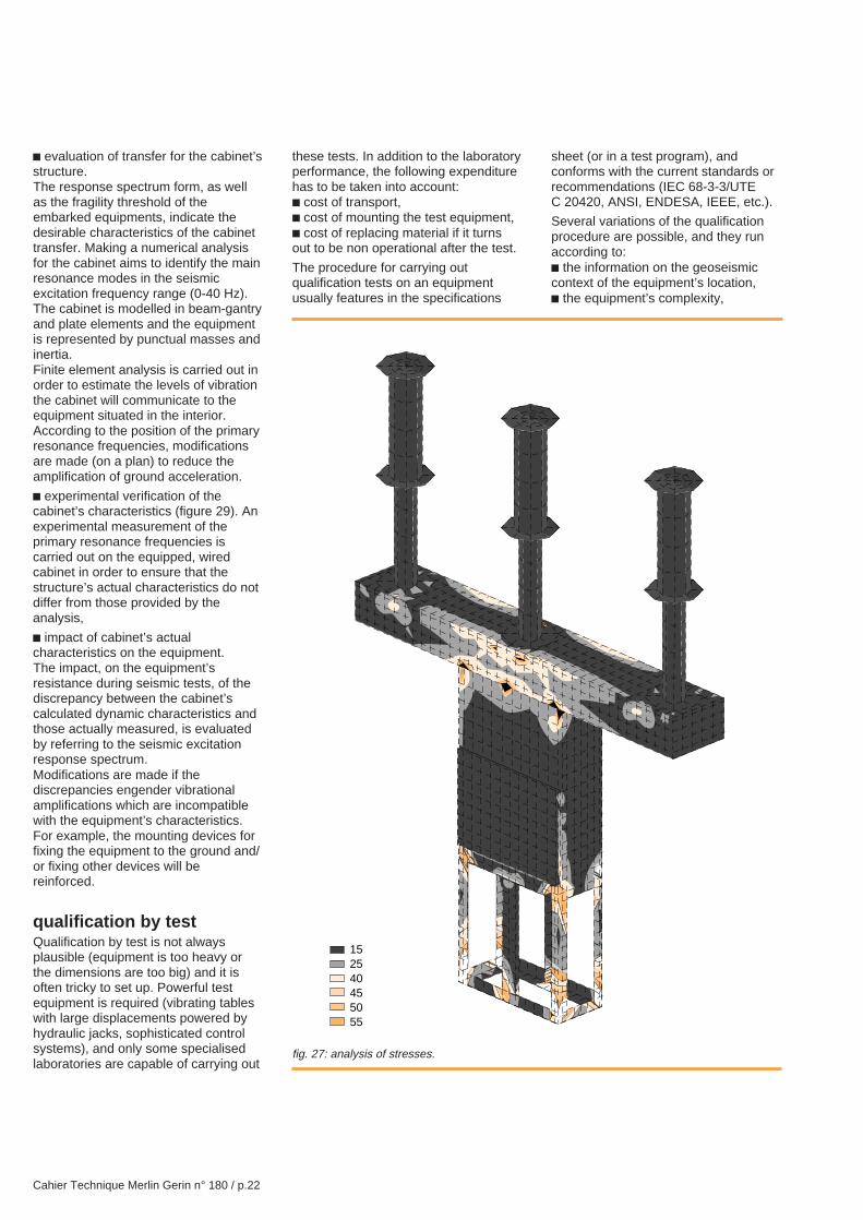
c sixth stage: verification of thedevice’s integrity and functioningunder seismic loads.This verification consists:v on the one hand, in verifying themechanical withstand capability of thestructure in terms of loads onconnections and stresses in the
materials when the circuit-breaker issubjected to accumulated seismicstresses and service stresses (weight,internal pressure, static loads on theterminals, wind) (see fig. 27 page 22,stresses in the HV circuit-breaker),v and on the other hand, in assuringthat the deformations which resultfrom the seismic sollicitation do notinterfere with the functioning of thedevice; this final verification is carriedout statically by imposing thedeformation obtained from theanalysis on the equipment, and byexecuting the different operations forwhich it is intended.
qualification by «real size»tests preceded bynumerical analysisEven if the material is to undergoqualification tests, it is still of interest,in order to save time and money, toprecede building and testing by a testmodel effectuated from plans.
Qualification of control/monitoringcabinetsControl/monitoring cabinets intendedfor nuclear power stations areconsidered in the following example.This equipment is subject to strictfunctioning safety regulations, and, tothis end, undergo «real size» tests forresistance to seismic sollicitations (seefig. 28, p. 23).In order to be able to present anequipment with higher guarantees ofgood resistance for testing, a certainnumber of simulations and investi-gations are carried out at the designstage. The procedure is as follows:c robustness evaluation of maindevices installed in the cabinet.For equipment which does not haveany historical data, a maximumwithstand capability test is carried outon the seismic excitation frequencyrange. This involves establishing theequipment’s fragility threshold (ifnecessary live). This data is then usefulfor defining the desired limitation of thecabinet transfer,
fig. 25: modal experimental analysis.fig. 26: resulting experimental modal shape(f = 3.8 Hz).
X
Y
Z
X
Y
Z
Cahier Technique Merlin Gerin n° 180 / p.22
c evaluation of transfer for the cabinet’sstructure.The response spectrum form, as wellas the fragility threshold of theembarked equipments, indicate thedesirable characteristics of the cabinettransfer. Making a numerical analysisfor the cabinet aims to identify the mainresonance modes in the seismicexcitation frequency range (0-40 Hz).The cabinet is modelled in beam-gantryand plate elements and the equipmentis represented by punctual masses andinertia.Finite element analysis is carried out inorder to estimate the levels of vibrationthe cabinet will communicate to theequipment situated in the interior.According to the position of the primaryresonance frequencies, modificationsare made (on a plan) to reduce theamplification of ground acceleration.
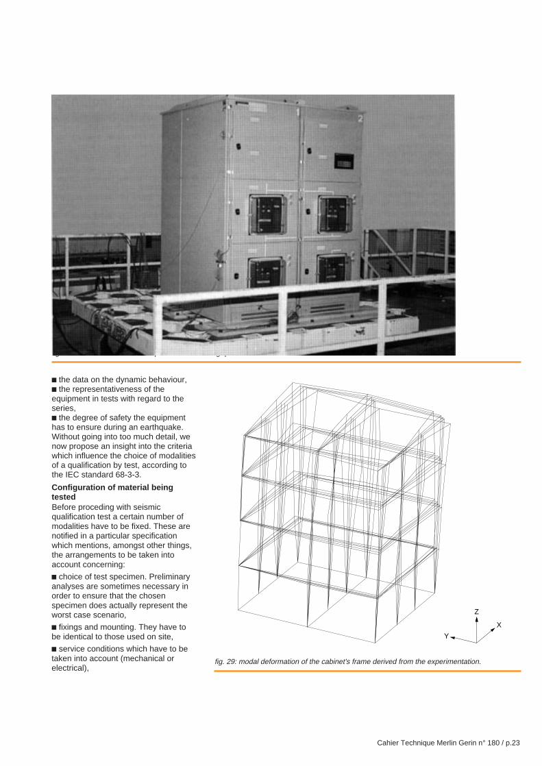
c experimental verification of thecabinet’s characteristics (figure 29). Anexperimental measurement of theprimary resonance frequencies iscarried out on the equipped, wiredcabinet in order to ensure that thestructure’s actual characteristics do notdiffer from those provided by theanalysis,
c impact of cabinet’s actualcharacteristics on the equipment.The impact, on the equipment’sresistance during seismic tests, of thediscrepancy between the cabinet’scalculated dynamic characteristics andthose actually measured, is evaluatedby referring to the seismic excitationresponse spectrum.Modifications are made if thediscrepancies engender vibrationalamplifications which are incompatiblewith the equipment’s characteristics.For example, the mounting devices forfixing the equipment to the ground and/or fixing other devices will bereinforced.
qualification by testQualification by test is not alwaysplausible (equipment is too heavy orthe dimensions are too big) and it isoften tricky to set up. Powerful testequipment is required (vibrating tableswith large displacements powered byhydraulic jacks, sophisticated controlsystems), and only some specialisedlaboratories are capable of carrying out
these tests. In addition to the laboratoryperformance, the following expenditurehas to be taken into account:c cost of transport,c cost of mounting the test equipment,c cost of replacing material if it turnsout to be non operational after the test.
The procedure for carrying outqualification tests on an equipmentusually features in the specifications
sheet (or in a test program), andconforms with the current standards orrecommendations (IEC 68-3-3/UTEC 20420, ANSI, ENDESA, IEEE, etc.).
Several variations of the qualificationprocedure are possible, and they runaccording to:c the information on the geoseismiccontext of the equipment’s location,c the equipment’s complexity,
fig. 27: analysis of stresses.
152540455055
Cahier Technique Merlin Gerin n° 180 / p.23
c the data on the dynamic behaviour,c the representativeness of theequipment in tests with regard to theseries,c the degree of safety the equipmenthas to ensure during an earthquake.Without going into too much detail, wenow propose an insight into the criteriawhich influence the choice of modalitiesof a qualification by test, according tothe IEC standard 68-3-3.
Configuration of material beingtestedBefore proceding with seismicqualification test a certain number ofmodalities have to be fixed. These arenotified in a particular specificationwhich mentions, amongst other things,the arrangements to be taken intoaccount concerning:
c choice of test specimen. Preliminaryanalyses are sometimes necessary inorder to ensure that the chosenspecimen does actually represent theworst case scenario,
c fixings and mounting. They have tobe identical to those used on site,
c service conditions which have to betaken into account (mechanical orelectrical),
fig. 28: LV cabinet for a nuclear power station during qualification tests.
fig. 29: modal deformation of the cabinet's frame derived from the experimentation.
X
Z
Y
Cahier Technique Merlin Gerin n° 180 / p.24
c functioning observed during the test,as well as the methods to be used inorder to check that the desiredperformance is maintained(measurement of the insulation or theelectrical continuity, breaking capacity,animation software, etc.).
Acceptance and/or bad functioningcriteria are classed according to threeseverities:
c severity 0: equipment shall not showdisfunctioning during and after theseismic test,
c severity 1: equipment can functionbadly during the seismic test but shallremain operational after the test,
c severity 2: equipment can functionbadly during the seismic test andrequires intervention or an adjustmentin order to regain its normal state,without replacement or repair beingnecessary.
Choice of test severity levelTwo classes have been providedaccording to the availability and/or theexactitude of the seismic characteristicsdefinition of the environment and theequipment.
c general seismic class: in this casethe acceleration to which the equipmentwill be subjected is normalized (severalperformance levels are usuallyproposed by the standard),
c specific seismic class: this concernsequipment for which the consideredseismic movement is the result of aseismological study (MHEL). It alsotakes the geographical implantationcharacteristics into account, in additionto those of the building or supportstructures. This is generally the case
for electrotechnical equipment,particularly for nuclear power stations,where the acceleration to which theequipment is subjected will be specifiedin the response spectrum.
Different types of testsDifferent methods are used in order torecreate the seismic environment on avibrating table. They differ in thenumber of directions in which areexcited simultaneously (single axis,multiaxis), and in the way in which theseismic waves are recreated by testmethods.
c single axis, multi-axis test.The seismic ground movement isproduced simultaneously in alldirections and, in order to simulate thisexactly, triaxial tables are required,whereas normal testing permits at bestbiaxial tests (two excitedsimultaneously axes).
Where no accuracy is availableconcerning the equipment’s seismicbehaviour, the biaxial test is recom-mended. It requires an installationwhich will permit simultaneousexcitation with independant wavesaccording to two of the equipment’spreferred axes; the test responsespectrum must be at least equivalent tothe required response spectrum.In order to effectuate testing accordingalong the 3rd axis, it is sufficient to turnthe equipment through 90° around avertical axis and effectuate the sametest again.
Single axis testing, executed accordingto the three preferred axes, is justifiedin the following circumstances:v if the equipment is only subjected toan excitation which could be
considered as monoaxial, on account ofits on site mounting conditions,v if there is no coupling (or weakcoupling) between the equipment’sthree preferred test axes, taken two bytwo.
c monofrequency and multifrequencywaves.In general the test wave used must:v produce a Test Response Spectrum(TRS) which is superior or equivalent tothe Required Response Spectrum(RRS) notified in the particularspecification,v have a peak maximum accelerationamplitude value equivalent or superiorto that of the RRS ground acceleration(Zero Period Acceleration (ZPA)),v reproduce the effects of a specifiedearthquake with a safety margin,v not include frequencies higherthan 35 Hz,v be of a duration which is at leastequivalent to that of the strong part ofthe earthquake; in general this isbetween 5 and 10 s.
The required response spectrum isgenerally broad band, and the use ofmultifrequency waves is recommended.Modern testing machines enable thiskind of wave to be generated, or to bemore precise, to pilot the testmachine, either from a time-historyprovided directly by the testspecification, or by synthesizing atime-history from a required responsespectrum (RRS), for a duration of 20seconds. In certain transfer casessuch as those found in buildings, theresponse spectrum is narrow band;testing can as a result be effectuatedin mono frequency waves.
Cahier Technique Merlin Gerin n° 180 / p.25
5. conclusion
The high degree of continuity ofservice required for electricaldistribution and control/monitoringdemands that all types ofenvironmental restrictions(mechanical, climatic,electromagnetic) are taken intoaccount. Seismic stresses,which areparticularly destructive are includedhere and they must be specified at thedesign stage of the equipment.
In order to do this it is necessary toknow the severity of the maximumhistorical earthquake likelihood in theform of a dimensioning spectrum, or,for mass-produced equipment, to
choose the level of severity of thenormalised seismic class.Today, an equipment’s mechanicalwithstand capability can beunderstood with a high degree ofprecision thanks to numerical analysisand finite element calcuation of thestresses
Proving that the equipment remainedoperational during or after theearthquake, is more difficult andgenerally requires the numericalanalysis to be combined with tests onthe operational elements. Theexamples of qualification by numericalanalysis and/or tests presented in
chapters 3 and 4, reveal the know-how of a company which, for manyyears has been providing countriesexposed to earthquakes withequipment for nuclear power stationsand other electrical equipment.
As for quality or electromagneticcompatibility , seismic withstand mustbe mastered at the design stage; ifthis is neglected then it is often difficultand more expensive to correctproblems at a later stage. As a result,numerical analysis and powerfulcalculation methods are used widely inthe «anti-seismic» design of electricaland electronic equipment.

Cahier Technique Merlin Gerin n° 180 / p.26
6. bibliography
Standardsc IEC 68-3-3 (UTE C20 420):Guidance. Seismic test methods forequipment.
c IEC 1166: HV circuit-breakers: guideto seismic qualification.
Merlin Gerlin Cahiers Techniquesc CT 85 (1977): Seismic withstandcapabilities of electrical equipment byP. PY, J.-Y. BERTHONNIER(presents technological solutions for HVcircuit-breakers).
Miscellaneous publicationsc AFPS90 recommendations fordrafting rules relative to works andinstallations to be realised in regionssubject to seismic volumes 1 and 2.
c Dynamic calculations of structures ina seismic zone by Alain CAPRA andVictor DAVIDOVICI.
c Revue des laboratoires d’essais,ASTE publication, n° 9, 31, 36, 39.

Cahier Technique Merlin Gerin n° 180 / p.27

Cahier Technique Merlin Gerin n° 180 / p.28
Real.: Illustration Technique - LyonEdition: DTE - Grenoble04-97 - 1500 - Printing: Clerc


