Download - EEE 2103 Circuit Theory I - Dr. Fehmi Bardak

EEE 2103 Circuit Theory I
Course Content


CHAPTER I: Circuit Variables
• 1.1 Electrical Engineering: An Overview
• 1.2 The International System of Units
• 1.3 Circuit Analysis: An Overview
• 1.4 Voltage and Current
• 1.5 The Ideal Basic Circuit Element
• 1.6 Power and Energy

1.1 Electrical Engineering: An Overview
• Electrical engineering is the profession concerned with systems that
produce, transmit, and measure electric signals.
• Electrical engineering combines the physicist’s models of natural
phenomena with the mathematician’s tools for manipulating those models
to produce systems that meet practical needs.
• Electrical systems pervade our lives; they are found in homes, schools,
workplaces, and transportation vehicles everywhere.
CLASSIFICATION OF ELECTRIC SYSTEMS
• Five major classifications of electrical systems:
– Communication systems
– Computer systems
– Control systems
– Power systems
– Signal-processing systems
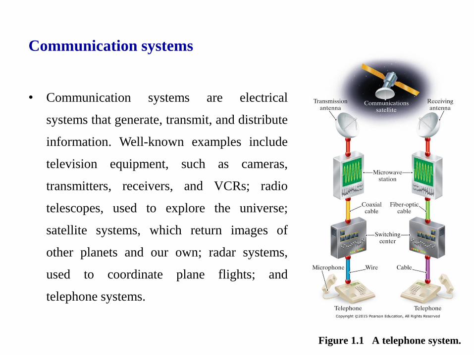
Communication systems
• Communication systems are electrical
systems that generate, transmit, and distribute
information. Well-known examples include
television equipment, such as cameras,
transmitters, receivers, and VCRs; radio
telescopes, used to explore the universe;
satellite systems, which return images of
other planets and our own; radar systems,
used to coordinate plane flights; and
telephone systems.
Figure 1.1 A telephone system.
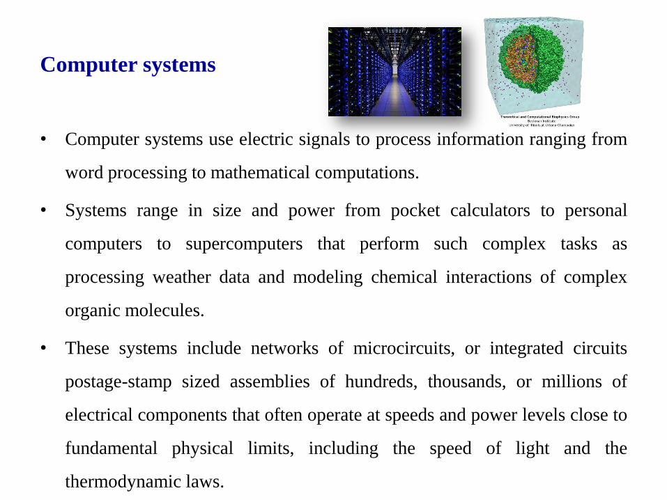
Computer systems
• Computer systems use electric signals to process information ranging from
word processing to mathematical computations.
• Systems range in size and power from pocket calculators to personal
computers to supercomputers that perform such complex tasks as
processing weather data and modeling chemical interactions of complex
organic molecules.
• These systems include networks of microcircuits, or integrated circuits
postage-stamp sized assemblies of hundreds, thousands, or millions of
electrical components that often operate at speeds and power levels close to
fundamental physical limits, including the speed of light and the
thermodynamic laws.
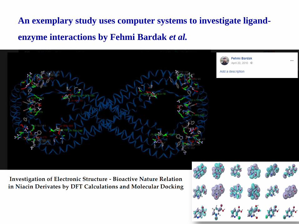
An exemplary study uses computer systems to investigate ligand-
enzyme interactions by Fehmi Bardak et al.

Control systems
• Control systems use electric signals to regulate processes.
• Examples include the control of temperatures, pressures, and flow rates in
an oil refinery;
– the fuel-air mixture in a fuel-injected automobile engine;
– mechanisms such as the motors, doors, and lights in elevators; and the
locks in the Panama Canal.
– The autopilot and auto landing systems that help to fly and land
airplanes are also familiar control systems.

Power systems
• Power systems generate and distribute electric power.
• Electric power, which is the foundation of our technology-based society,
usually is generated in large quantities by nuclear, hydroelectric, and
thermal (coal-, oil-, or gas-fired) generators.
• Power is distributed by a grid of conductors that crisscross the country. A
major challenge in designing and operating such a system is to provide
sufficient redundancy and control so that failure of any piece of equipment
does not leave a city, state, or region completely without power.
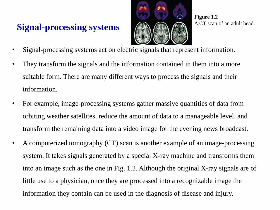
Signal-processing systems
• Signal-processing systems act on electric signals that represent information.
• They transform the signals and the information contained in them into a more
suitable form. There are many different ways to process the signals and their
information.
• For example, image-processing systems gather massive quantities of data from
orbiting weather satellites, reduce the amount of data to a manageable level, and
transform the remaining data into a video image for the evening news broadcast.
• A computerized tomography (CT) scan is another example of an image-processing
system. It takes signals generated by a special X-ray machine and transforms them
into an image such as the one in Fig. 1.2. Although the original X-ray signals are of
little use to a physician, once they are processed into a recognizable image the
information they contain can be used in the diagnosis of disease and injury.
Figure 1.2
A CT scan of an adult head.

Interaction between engineering disciplines
• Although an engineer is interested in a
specific area, he/she must also be
knowledgeable in the other areas that
are related to subject of interest.
• The fundamental rules and circuit
analysis techniques that will be
learned throughout this course applies
to all fields mentioned so far.
Figure 1.3 An airplane.

Circuit Theory
• An electric circuit is a mathematical model that approximates the behavior of an
actual electrical system.
• The models, the mathematical techniques, and the language of circuit theory will
form the intellectual framework for your future engineering endeavors.
• Circuit theory is a special case of electromagnetic field theory: the study of static
and moving electric charges. Although generalized field theory might seem to be an
appropriate starting point for investigating electric signals, its application is not
only cumbersome but also requires the use of advanced mathematics. Consequently,
a course in electromagnetic field theory is not a prerequisite to understanding the
material in this book. We do, however, assume that you have had an introductory
physics course in which electrical and magnetic phenomena were discussed.

Assumptions made in circuit theory
• Three basic assumptions permit us to use circuit theory, rather than
electromagnetic field theory, to study a physical system represented by an
electric circuit. These assumptions are as follows:
• Electrical effects happen instantaneously throughout a system.
• The net charge on every component in the system is always zero.
• There is no magnetic coupling between the components in a system.
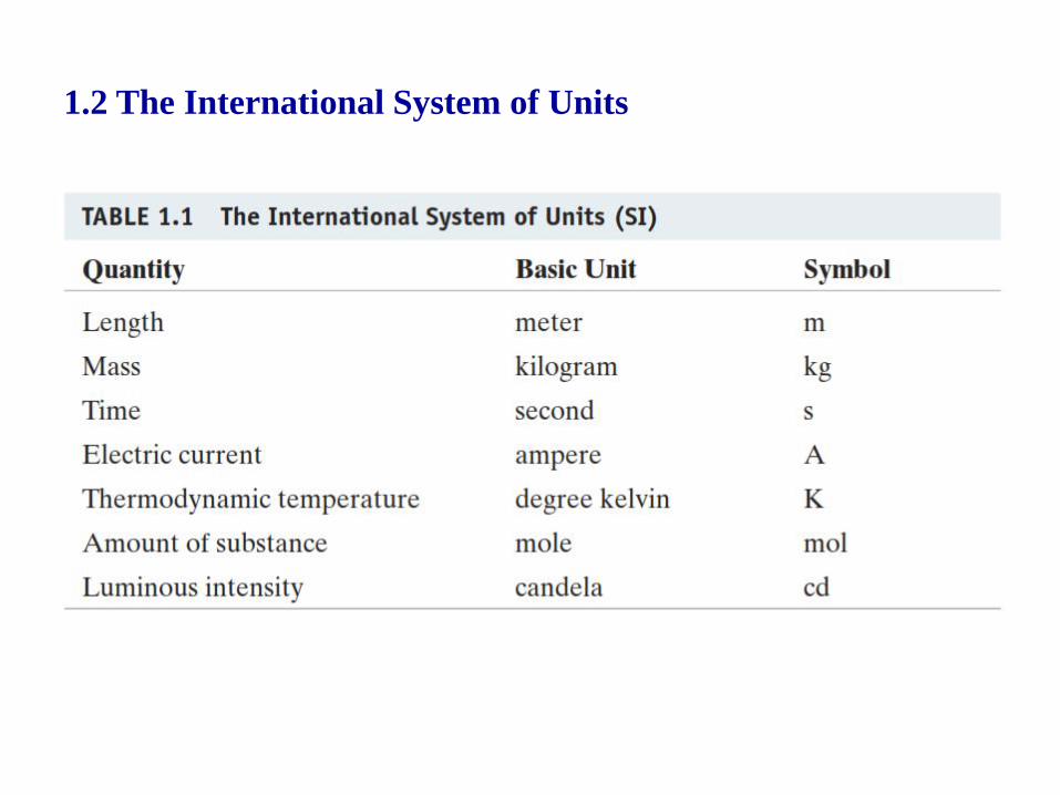
1.2 The International System of Units


1.3 Circuit Analysis: An Overview
• A commonly used mathematical
model for electrical systems is a
circuit model.
• The elements that comprise the circuit
model are called ideal circuit
components.
• The physical prototype is an actual
electrical system, constructed from
actual electrical components.

1.4 Voltage and Current
• Voltage is the energy per unit charge created by the separation.

• The rate of charge flow is known as the electric current,
• Although current is made up of discrete, moving electrons, we do not need
to consider them individually because of the enormous number of them.
Rather, we can think of electrons and their corresponding charge as one
smoothly flowing entity. Thus, i is treated as a continuous variable.
1.4 Voltage and Current

1.5 The Ideal Basic Circuit Element
• An ideal basic circuit element has three attributes:
– (1) it has only two terminals, which are points of connection to
other circuit components;
– (2) it is described mathematically in terms of current and/or
voltage; and
– (3) it cannot be subdivided into other elements.

Passive sign convention
Whenever the reference direction for the current in an element is
in the direction of the reference voltage drop across the element
(as in Fig. 1.5), use a positive sign in any expression that relates
the voltage to the current. Otherwise, use a negative sign.

1.6 Power and Energy
• Power is energy per unit time.

1.6 Power and Energy
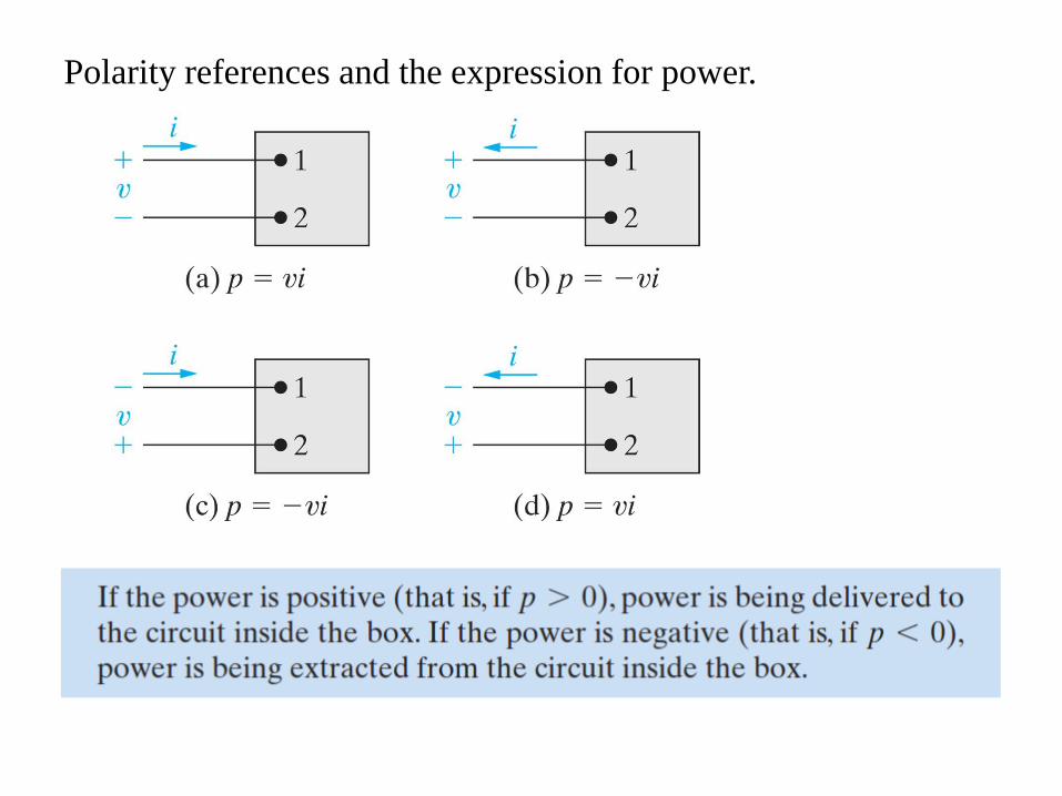
Polarity references and the expression for power.


