
1.101
SG85F
SG115F
3
SG63F
2
1
Subject to alterations. (14_Ge)
Series SG63FSI63 3,5.350 FI - SI 17.60 FI
Series SG85FSI 10.200 FI - SI 55.40 FI
Series SG115FSI 50.80 FI - SI 180.12 FI
1 See 3.6
Mounting Floating foot (standard fitting) Torque mount
Special versions Other drive speeds and other drive torques on request
Door controls Simple connection to the limit switch by means of non-interchangeable plug con-nections allowing simple exchange with other GfA door controls
Control voltage: 24V DC Frequency: 50 / 60 Hz Mains supply at motors with 0,85/1,5kW: 1N~230V, 3N~400V
Mains supply at motors with 4,5kW: 3N~400V, 3~400V
Details of all GfA door controls can be found in Section 8.
Emergency manual operation Hand crank NHK Hand chain operator KNH
12
Limit switchesDigital limit DES
Absolute encoder, after a power failure, re-adjustment is not required
3
ELEKTROMATEN® SI FI“Safedrive®” with built-on frequency inverter
For driving: High-speed sectional doors and high-speed rolling doors which require an anti-fallback device
“Safedrive FI®” ELEKTROMATEN SI are special drives for industrial doors which require an anti-fallback device. The patented safety brake is built into the gear. The drive unit is fitted directly to the door shaft. Safedrive ELEKTROMATEN SI FI comprises of: Worm gear with safety brake and hollow shaft, emergency manual operator, integrated limit switches and electrical motor with built-on frequency inverter.
Patented built-in safety brake Safety against failure of worm or wheel Independent of speed / direction Maintenance free, self-monitoring Excellent damping characteristics in operation
Built-on frequency inverter to be used with door controls TS 970, TS 971 or TS 981
Individual adjustable output speed 1 The speed appears directly into the display – extra work to evaluate
frequency and speed is not required Soft start and soft stop Automatic optimising of acceleration and deceleration speed Adjustable distance for acceleration and deceleration speed Individual adjustment and programming of all functions from the
ground by a rotary switch and display
Approvals and certificates
ELEKTROMATEN and FI-motors Type test according to: DIN EN 12453 DIN EN 60335-1 DIN EN 60335-2-103 TÜV NORD CERT GmbH
Built-in safety brake Certificate of conformity according to:DIN EN 12604 / 12605 TÜV SÜD Industrieservice GmbH

1.102
SG85F
SG85F
SG85F
100 150 200
25-20025-11025-90
19-14019-8019-75
18-10018-5518-55
30 / 40 30 / 40 30 / 40
1020 1020 1020
TorFV 4 / 025
TorFV 4 / 025
TorFV 4 / 025
1,50 1,50 1,50
1N~230V 1N~230V 1N~230V
50 / 60 50 / 60 50 / 60
60 60 45
3x1,5² / 10A
3x1,5² / 10A
3x1,5² / 10A
20 20 20
175 / 195 195 / 217 203 / 226
35 35 35
(9.057) (9.057) (9.057)
50001422 50001422 50001422
10004460 (Ø30) 10004462 (Ø40)
10004456 (Ø30) 10004459 (Ø40)
10004224 (Ø30) 10004227 (Ø40)
SG63F
SG63F
SG63F
SG63F
SG63F
35 50 80 130 170
30-35030-15030-100
30-25030-15030-100
30-18030-9030-90
18-10018-8018-60
8-608-358-35
25 / 25,4 / 30 / 31,75 / 40 25 / 25,4 / 30 / 31,75 / 40 25 / 25,4 / 30 / 31,75 / 40 25 / 25,4 / 30 / 31,75 / 40 25 / 25,4 / 30 / 31,75 / 40
873 873 873 873 873
TorFV 4 / 024
TorFV 4 / 024
TorFV 4 / 024
TorFV 4 / 024
TorFV 4 / 024
0,85 0,85 0,85 0,85 0,85
1N~230V 1N~230V 1N~230V 1N~230V 1N~230V
50 / 60 50 /60 50 /60 50 /60 50 /60
60 60 45 45 30
3x1,5² / 10A
3x1,5² / 10A
3x1,5² / 10A
3x1,5² / 10A
3x1,5² / 10A
20 20 20 20 20
173 / 140 199 / 161 217 / 175 225 / 182 157 / 127
22 22 22 22 22
(9.053) (9.053) (9.053) (9.053) (9.053)
50001458 50001458 50001458 50001601 50001458
10003987 (Ø25) 1000xxxx (Ø25,4) 10003928 (Ø30) 1000xxxx (Ø31,75) 10004037 (Ø40)
10003888 (Ø25) 10003889 (Ø25,4) 10003745 (Ø30) 1000xxxx (Ø31,75) 10003881 (Ø40)
10003896 (Ø25) 10003897 (Ø25,4) 10003843 (Ø30) 1000xxxx (Ø31,75) 10003898 (Ø40)
10004184 (Ø25) 10004283 (Ø25,4) 10004116 (Ø30) 10004268 (Ø31,75) 10004185 (Ø40)
10004186 (Ø25) 10003900 (Ø25,4) 10003844 (Ø30) 10003901 (Ø31,75) 10003902 (Ø40)
Subject to alterations. (14_Ge)
1.2 SG85F Output torque 100Nm - 200Nm / 1,5kW
1.1 SG63F Output torque 35Nm - 170Nm / 0,85kW
Footnotes under 1.5
ELEKTROMATEN Series
SI 10.200 FI SI 15.140 FI SI 20.100 FI
Output torque Nm
Output speed OPEN CLOSE > 2,5m CLOSE ≤ 2,5m 1
rpm
Output shaft / hollow shaft (Ø) mm
Locking torque 2 Nm
Safety brake (approval number)
Motor power kW
Supply voltage V
Operating frequency Hz
Max. movements per hour 3
Supply side wiring / fusing (delayed action)
Limit switch range 4
Max. hand force NHK / KNH 5 N
Weight kg
Spare parts: Catalogue page 6
Part no. installation drawing (dxf, dwg)
Part no. ELEKTROMATEN
ELEKTROMATEN Series
SI63 3,5.350 FI SI63 5.250 FI SI63 8.180 FI SI 13.100 FI SI 17.60 FI
Output torque Nm
Output speed OPEN CLOSE > 2,5m CLOSE ≤ 2,5m 1
rpm
Output shaft / hollow shaft (Ø) mm
Locking torque 2 Nm
Safety brake (approval number)
Motor power kW
Supply voltage V
Operating frequency Hz
Max. movements per hour 3
Supply side wiring / fusing (delayed action)
Limit switch range 4
Max. hand force NHK / KNH 5 N
Weight kg
Spare parts: Catalogue page 6
Part no. installation drawing (dxf, dwg)
Part no. ELEKTROMATEN
1. Technical data

1.103
SG85F
SG85F
SG85F
SG85F
250 250 400 450
10-6010-3510-35
18-8018-5018-50
9-409-359-24
7-157-157-15
30 / 31,75 / 40 30 / 31,75 / 40 40 40
1020 1020 1020 1170
TorFV 4 / 025
TorFV 4 / 025
TorFV 4 / 025
TorFV 4 / 025
1,50 1,50 1,50 1,50
1N~230V 1N~230V 1N~230V 1N~230V
50 / 60 50 / 60 50 / 60 50 / 60
45 45 30 14
3x1,5² / 10A
3x1,5² / 10A
3x1,5² / 10A
3x1,5² / 10A
20 20 20 20
200 / 99 233 / 115 255 / 126 153 / 170
35 35 35 33
(9.057) (9.057) (9.057) (9.057)
50001422 50001422 50001422 50001554
10003845 (Ø30)10004054 (Ø31,75)10003871 (Ø40)
10003827 (Ø30)10003828 (Ø31,75)10003826 (Ø40)
10003672 10004022
SG85F
SG85F
SG85F
SG85F
250 350 450 550
17-15017-7017-70
15-10015-5515-55
7-607-357-35
8-408-308-30
40 40 40 40
1170 1170 1170 1400
TorFV 4 / 025
TorFV 4 / 025
TorFV 4 / 025
TorFV 4 / 025
4,50 4,50 4,50 4,50
3~400V 3~400V 3~400V 3~400V
50 / 60 50 / 60 50 / 60 50 / 60
45 30 30 16
5x1,5² / 10A
5x1,5² / 10A
5x1,5² / 10A
5x1,5² / 10A
20 20 20 20
353 / 174 376 / 186 252 / 125 320 / 158
45 45 43 43
(9.057) (9.057) (9.057) (9.057)
50001456 50001456 50001435 50001435
10003834 10003833 10003903 10003738
Subject to alterations. (14_Ge)
Footnotes under 1.5
1.3 SG85F Output torque 250Nm - 450Nm / 1,5kW
1.4 SG85F Output torque 250Nm - 550Nm / 4,5kW
ELEKTROMATEN Series
SI 25.150 FI SI 35.100 FI SI 45.60 FI SI 55.40 FI
Output torque Nm
Output speed OPEN CLOSE > 2,5m CLOSE ≤ 2,5m 1
rpm
Output shaft / hollow shaft (Ø) mm
Locking torque 2 Nm
Safety brake (approval number)
Motor power kW
Supply voltage V
Operating frequency Hz
Max. movements per hour 3
Supply side wiring / fusing (delayed action)
Limit switch range 4
Max. hand force NHK / KNH 5 N
Weight kg
Spare parts: Catalogue page 6
Part no. installation drawing (dxf, dwg)
Part no. ELEKTROMATEN
ELEKTROMATEN Series
SI 25.60 FI SI 25.80 FI SI 40.40 FI SI 45.15 FI
Output torque Nm
Output speed OPEN CLOSE > 2,5m CLOSE ≤ 2,5m 1
rpm
Output shaft / hollow shaft (Ø) mm
Locking torque 2 Nm
Safety brake (approval number)
Motor power kW
Supply voltage V
Operating frequency Hz
Max. movements per hour 3
Supply side wiring / fusing (delayed action)
Limit switch range 4
Max. hand force NHK / KNH 5 N
Weight kg
Spare parts: Catalogue page 6
Part no. installation drawing (dxf, dwg)
Part no. ELEKTROMATEN

1.104
SG115F
SG115F
SG115F
SG115F
SG115F
500 750 1000 1400 1800
22-8022-4522-30
8-458-288-28
5-305-185-18
5-205-145-14
5-125-125-12
55 55 55 55 60
2840 2840 2840 2840 4445
TorFV 4 / 026
TorFV 4 / 026
TorFV 4 / 026
TorFV 4 / 026
TorFV 4 / 026
4,50 4,50 4,50 4,50 4,50
3~400V 3~400V 3~400V 3~400V 3~400V
50 / 60 50 / 60 50 / 60 50 / 60 50 / 60
30 30 12 10 8
5x1,5² / 10A
5x1,5² / 10A
5x1,5² / 10A
5x1,5² / 10A
5x1,5² / 10A
20 20 20 20 20
287 / 232 290 / 234 206 / 166 263 / 212 348 / 281
58 58 65 65 68
(09.058) (09.058) (09.058) (09.058) (09.058)
50001439 50001439 50001424 50001424 50001591
10003743 10003831 10003917 10003697 10004055
101,6 x 3,6 3289 -- -- -- -- -- -- -- --
108,0 x 3,6 3125 5050 5625 -- -- -- -- -- --
133,0 x 4,0 2614 4183 4706 -- -- -- -- -- --
159,0 x 4,5 2235 3575 4022 4915 4469 6704 -- -- --
177,8 x 5,0 2022 3236 3640 4449 4044 6067 8089 11325 --
193,7 x 5,4 1872 2995 3369 4118 3744 5615 7487 10482 13477
219,1 x 5,9 -- 2677 3011 3680 3346 5019 6692 9368 12045
244,5 x 6,3 -- -- -- 3327 3025 4537 6049 8469 10888
273,0 x 6,3 -- -- -- -- -- 4096 5461 7645 9829
298,5 x 7,1 -- -- -- -- -- 3768 5024 7033 9042
323,9 x 7,1 -- -- -- -- -- -- 4653 6514 8375
Ø 160 1913 2813 4500 5063 6188 5625 -- -- --
Ø 200 1530 2250 3600 4050 4950 4500 6750 9000 12600
Subject to alterations. (14_Ge)
1.5 SG115F Output torque 500Nm - 1800Nm / 4,5kW
F = Lift [N] Read note in 3.2
F = Lift [N] Read notes in 3.2 and 3.7
Includes 10% friction Select not mentioned drives as required by the door construction
2.1 Roller shutters Tube EN 10220 [mm]
SI 25.60 FISI 25.80 FI
F [N]
SI 40.40 FI F [N]
SI 45.15 FISI 45.60 FI
F [N]
SI 55.40 FI F [N]
SI 50.80 FIF [N]
SI 75.45 FIF [N]
SI 100.30 FI F [N]
SI 140.20 FIF [N]
SI 180.12 FI F [N]
2.2 Sectional doors Cable drum [mm]
SI 17.60 FI F [N]
SI 25.60 FISI 25.80 FI
F [N]
SI 40.40 FI F [N]
SI 45.15 FISI 45.60 Fi
F [N]
SI 55.40 FI F [N]
SI 50.80 FI F [N]
SI 75.45 FI F [N]
SI 100.30 FI F [N]
SI 140.20 FIF [N]
ELEKTROMATEN Series
SI 50.80 FI SI 75.45 FI SI 100.30 FI SI 140.20 FI SI 180.12 FI
Output torque Nm
Output speed OPEN CLOSE > 2,5m CLOSE ≤ 2,5m 1
rpm
Output shaft / hollow shaft (Ø) mm
Locking torque 2 Nm
Safety brake (approval number)
Motor power kW
Supply voltage V
Operating frequency Hz
Max. movements per hour 3
Supply side wiring / fusing (delayed action)
Limit switch range 4
Max. hand force NHK / KNH 5 N
Weight kg
Spare parts: Catalogue page 6
Part no. installation drawing (dxf, dwg)
Part no. ELEKTROMATEN
2. Selection chart
Generally applies: Protection class IP65, permissible temperature range +5°C...+40°C (+60°C), operating sound pressure level SPL ‹70 dB(A)1 See 3.6 · 2 See 3.5 · 3 When using a temperature range of +40°C...+60°C use half of maximum movements per hour, see also 3.2 · 4 Maximum revolutions of hollow shaft, E20 standard with DES · 5 See 3.4 · 6 List of spare parts for all ELEKTROMATEN SI FI does not apply to motor and gear, we can draw up article- and / or model-specific lists of spare parts on request
Includes 20% friction for single-wall profiles (profile thickness 20 mm) Select not mentioned drives as required by the door construction

1.105
2
3
4
5
6
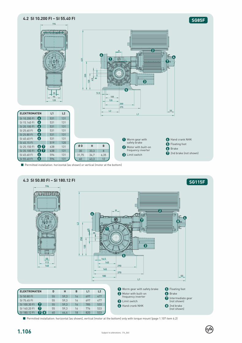
Ø D H B
25 28,3 825,4 28,4 6,3530 33,3 8
31,75 34,7 6,3540 43,3 12
1
ELEKTROMATEN L1 L2
609 111
593 956
7
7
SG63F
}Subject to alterations. (14_Ge)
1 Worm gear with safety brake
2 Motor with built-on frequency inverter
3 Limit switch
Permitted installation: horizontal (as shown) or vertical (motor at the bottom)
3.1 European directive
In accordance with the product standard EN 13241-1 Doors- and EN 12453 Safety in use of power operated doors-Requirements.
3.2 Selection chart / Movements per hour
Reduce weight of the door if the stated number of movements per hour is exceeded (See item - 1. Technical data) – e.g. high frequently used doors (enquire).The selection chart includes 20% friction for roller shutters with single-wall profiles (profile thickness 20mm) and 10% friction for sectional doors.Reduce the weight by a further 20% for vertical lifted doors and insulated shutters with double walled, thick and / or deep sections. Do not calculate using the tube diameter. The high-est torque will occur normally after 1-2 turns of the barrel from close.
3.3 Gear self-braking / Brake
Drives without an electric brake have a self-sustaining worm gear and stop automatically.On drives with an electric brake, stopping is achieved by the external brake. Brake inspection must always be carried out by qualified service engineers.
In accordance with EN 12453 and 12604 hand force up to 390 N is permissible. For large, heavy doors, manual operation is only used for closing the door. In the case of drive units with an electric brake; emergency manual operation is carried out against the closed brake (Read note in 3.3).
3.4 Manual operation
3.7 Cable / Cable drums
When calculating the cable size the max. permitted door weight is required with a safety of 6x for the cables require-ment of EN 12604. Cable drum selection – ensure that two turns of the cable remain on the drum at all times. The diameter of the cable drum must be at least 20x the diameter of the cable.
3.6 Output speed
The maximum admissible speed is dependent on the door construction and type of the door. All materials must be desi-gned to be used for doors with higher speeds.The admissible closing speed shall be adjusted so that the ope-rating forces must comply with EN 12453
4 Hand crank NHK
5 Floating foot
6 Brake on motor
7 Brake on gear
3. Notes
4. Dimensions
4.1 SI63 3,5.350 FI – SI 17.60 FI
The permissible loads on walls, fastenings, mountings and transmission elements must not be exceeded, even for maxi-mum holding torques or locking torques.
3.5 Locking torque / Holding torque
SI 13.100 FISI63 3,5.350 FISI63 5.250 FISI63 8.180 FISI 17.60 FI
1.106
1
3
4
5
62
7
1
2
3
4
5
6
7
8
ELEKTROMATEN D H B L1 L2
55 59,3 16 697 47755 59,3 16 697 47755 59,3 16 785 53355 59,3 16 776 53360 64,4 18 820 5338
Ø D H B
30 33,3 831,75 34,7 6,35
40 43,3 12
7
77
SG85F
SG115F
ELEKTROMATEN L1 L2
531 131531 131531 131531 131531 131531 131519 120638 131638 131594 131594 131
77
66
6
6
66
6
6
66
Subject to alterations. (14_Ge)
Permitted installation: horizontal (as shown), vertical (motor at the bottom) only with torque mount (page 1.107 item 6.2)
1 Worm gear with safety brake
2 Motor with built-on frequency inverter
3 Limit switch
4 Hand crank NHK
5 Floating foot
6 Brake
7 2nd brake (not shown)
Permitted installation: horizontal (as shown) or vertical (motor at the bottom)
1 Worm gear with safety brake
2 Motor with built-on frequency inverter
3 Limit switch
4 Hand crank NHK
5 Floating foot
6 Brake
7 Intermediate gear (not shown)
8 2nd brake (not shown)
4.2 SI 10.200 FI – SI 55.40 FI
4.3 SI 50.80 FI – SI 180.12 FI
SI 50.80 FISI 75.45 FISI 100.30 FISI 140.20 FISI 180.12 FI
SI 10.200 FISI 15.140 FISI 20.100 FISI 25.60 FISI 25.80 FISI 40.40 FISI 45.15 FISI 25.150 FISI 35.100 FISI 45.60 FISI 55.40 FI
1.107
3
1
2
L H
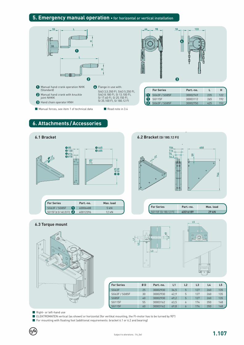
SG63F / SG85F 30002749 235 122SG115F 30003112 265 192SG63F / SG85F 30002750 425 152
1
21
40016189 29 kNSG63F / SG85F 40006488 5 kN
40012396 12 kN12
Ø D L1 L2 L3 L4 L5
SG63F 25 30002930 36,5 5 127 260 135SG63F / SG85F 30 30002930 42,9 5 127 260 135SG85F 40 30002930 49,2 5 127 260 135SG115F 55 30003162 63,5 6 174 350 148SG115F 60 30003162 69,8 6 174 350 148
4
Subject to alterations. (14_Ge)
Manual forces, see item 1 of technical data
1 Manual hand crank operation NHK (Standard)
2 Manual hand crank with knuckle joint NHKK
3 Hand chain operator KNH
Right- or left-hand use ELEKTROMATEN vertical (as shown) or horizontal (for vertikal mounting, the FI-motor has to be turned by 90°) For mounting with floating foot (additional requirements: bracket 6.1 or 6.2 and bearing)
6.3 Torque mount
Read note in 3.4
4 Flange in use with:
SI63 3,5.350 FI, SI63 5.250 FI, SI63 8.180 FI, SI 13.100 FI, SI 17.60 FI, SI 25.150 FI, SI 35.100 FI, SI 180.12 FI
For Series Part.-no.
For Series Part.-no. Max. load
SG115F (SI 180.12 FI) 40016189 29 kN
For Series Part.-no. Max. load
SG115F (≤ SI 140.20 FI)
For Series Part.-no.
6.1 Bracket 6.2 Bracket (SI 180.12 FI)
5. Emergency manual operation • for horizontal or vertical installation
6. Attachments / Accessories
1.108
L
D2
D1
D3
B
D1 D2 D3 L
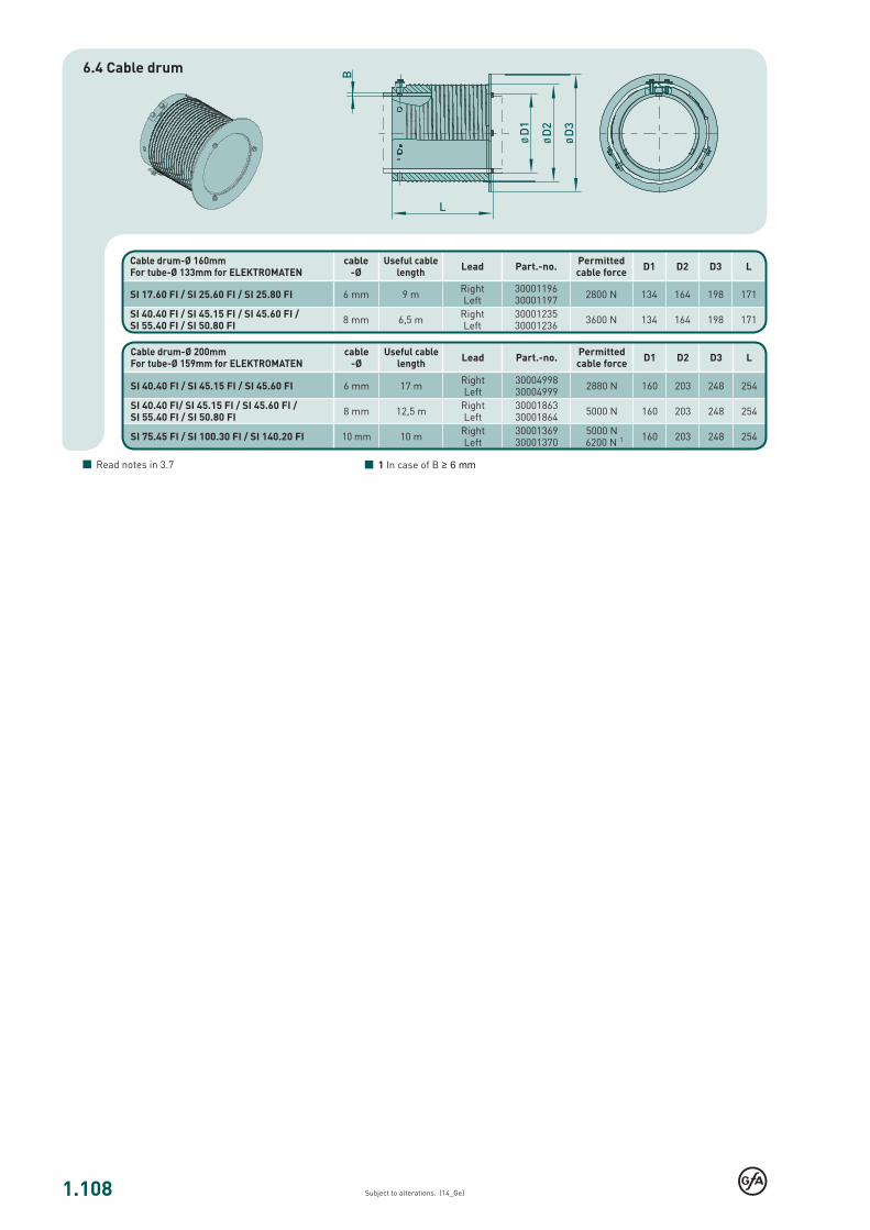
6 mm 9 m 3000119630001197 2800 N 134 164 198 171
8 mm 6,5 m 3000123530001236 3600 N 134 164 198 171
D1 D2 D3 L
6 mm 17 m 3000499830004999 2880 N 160 203 248 254
8 mm 12,5 m 3000186330001864 5000 N 160 203 248 254
10 mm 10 m 3000136930001370
5000 N 6200 N 1 160 203 248 254
Subject to alterations. (14_Ge)
6.4 Cable drum
Read notes in 3.7
Cable drum-Ø 160mm For tube-Ø 133mm for ELEKTROMATEN
cable -Ø
Useful cable length Lead Part.-no. Permitted
cable force
SI 17.60 FI / SI 25.60 FI / SI 25.80 FI RightLeft
SI 40.40 FI / SI 45.15 FI / SI 45.60 FI / SI 55.40 FI / SI 50.80 FI
RightLeft
Cable drum-Ø 200mm For tube-Ø 159mm for ELEKTROMATEN
cable -Ø
Useful cable length Lead Part.-no. Permitted
cable force
SI 40.40 FI / SI 45.15 FI / SI 45.60 FI RightLeft
SI 40.40 FI/ SI 45.15 FI / SI 45.60 FI / SI 55.40 FI / SI 50.80 FI
RightLeft
SI 75.45 FI / SI 100.30 FI / SI 140.20 FI RightLeft
1 In case of B ≥ 6 mm

1.121
SG186F
2
1
Subject to alterations. (14_Dd)
ELEKTROMATEN® SI FISafedrive® with built-on frequency inverter
For driving: Non-balanced sectional doors, roller shutters and rolling grilles which require an anti-fallback device
Series SG186F SI 500.10 FI
“Safedrive® FI” ELEKTROMATEN SI are special drives for industrial doors which require an anti-fallback device. The patented safety brake is built into the gear. The drive unit is fitted directly to the door shaft. Safedrive ELEKTROMATEN SI FI comprises of: Worm gear with safety brake and hollow shaft, emergency manual operator, integrated limit switches and electrical motor with built-on frequency inverter.
Patented built-in safety brake Safety against failure of worm or wheel Independent of speed / direction Maintenance free, self-monitoring Excellent damping characteristics in operation
Built-on frequency inverter to be used with door controls TS 970, TS 971 or TS 981
Individual adjustable output speed 1 The speed appears directly into the display – extra work to evaluate
frequency and speed is not required Soft start and soft stop Automatic optimising of acceleration and deceleration speed Adjustable distance for acceleration and deceleration speed Individual adjustment and programming of all functions from the
ground by a rotary switch and display
Approvals and certificates
1 See 3.6
Mounting Floating foot (Fitting requires a torque mount system)
Door controls Simple connection to the limit switch by means of non-interchangeable plug con-nections allowing simple exchange with other GfA door controls
Control voltage: 24V Frequency: 50 / 60 Hz Mains supply: 3N~400V, 3~400V
Details of all GfA door controls can be found in Section 8.
Built-in safety brake Certificate of conformity according to:DIN EN 12604 / 12605 ift Rosenheim GmbH
Emergency manual operation Hand chain operator KNH 1
ELEKTROMATEN and FI-motors Type test according to: DIN EN 12453 DIN EN 60335-1 DIN EN 60335-2-103 TÜV NORD CERT GmbH
Limit switchesDigital limit DES
Absolute encoder, after a power failure, re-adjustment is not required
2
1.122
SG186F
5000
6-102-52-5
100
8255
11-003301-PR
4,50
3~400
50 / 60
8
5x1,5² / 10A
10
261
132
50001578
10004095
298,5 x 7,1 25118 6,7 - 16,7
323,9 x 7,1 23294 7,2 - 18,0
368,0 x 8,0 20627 8,1 - 20,3
406,4 x 8,8 18762 8,9 - 22,3
Subject to alterations. (14_Dd)
F = Lift [N] vb = Range of speed
Includes 20% friction for single-wall profiles (profile thickness 20 mm) Read note in 3.2
ELEKTROMATEN Series
SI 500.10 FI
Output torque Nm
Output speed OPEN CLOSE > 2,5m CLOSE ≤ 2,5m 1
rpm
Output shaft / hollow shaft (Ø) mm
Locking torque 2 Nm
Safety brake (approval number)
Motor power kW
Supply voltage V
Operating frequency Hz
Max. movements per hour 3
Supply side wiring / fusing (delayed action))
Limit switch range 4
Max. hand force KNH 5 N
Weight kg
Part no. installation drawing (dxf, dwg)
Part no. ELEKTROMATEN
Roller shutters Tube EN 10220 [mm]
SI 500.10 FI F [N] vb [cm/s]
1. Technical data
2. Selection chart
Generally applies: Protection class IP65, permissible temperature range +5°C...+40°C (+60°C), operating sound pressure level SPL ‹70 dB(A)1 See 3.6 · 2 See 3.5 · 3 When using a temperature range of +40°C...+60°C use half of maximum movements per hour, see also 3.2 · 4 Maximum revolutions of hollow shaft · 5 See 3.4

1.123
12
4
3
6
5
7
SG186F
Subject to alterations. (14_Dd)
3.1 European directive
In accordance with the product standard EN 13241-1 Doors- and EN 12453 Safety in use of power operated doors-Requirements.
Permitted installation: horizontal with an additional torque mount system, see 6
3. Notes
4. Dimensions
SI 500.10 FI
3.2 Selection chart / Movements per hour
Reduce weight of the door if the stated number of movements per hour is exceeded (See item - 1. Technical data) – e.g. high frequently used doors (enquire).The selection chart includes 20% friction for roller shutters with single-wall profiles (profile thickness 20mm) and 10% friction for sectional doors.Reduce the weight by a further 20% for vertical lifted doors and insulated shutters with double walled, thick and / or deep sections. Do not calculate using the tube diameter. The high-est torque will occur normally after 1-2 turns of the barrel from close.
3.3 Gear self-braking / Brake
Drives without an electric brake have a self-sustaining worm gear and stop automatically.On drives with an electric brake, stopping is achieved by the external brake. Brake inspection must always be carried out by qualified service engineers.
In accordance with EN 12453 and 12604 hand force up to 390 N is permissible. For large, heavy doors, manual operation is only used for closing the door. In the case of drive units with an electric brake; emergency manual operation is carried out against the closed brake (Read note in 3.3).
3.4 Manual operation
3.6 Output speed
The maximum admissible speed is dependent on the door construction and type of the door. All materials must be desi-gned to be used for doors with higher speeds.The admissible closing speed shall be adjusted so that the ope-rating forces must comply with EN 12453
The permissible loads on walls, fastenings, mountings and transmission elements must not be exceeded, even for maxi-mum holding torques or locking torques.
3.5 Locking torque / Holding torque
1 Worm gear with safety brake
2 Motor with built-on frequency inverter
3 Limit switch
4 Hand chain operaotr KNH
5 Floating foot
6 Brake
7 Fitting belt
1.124
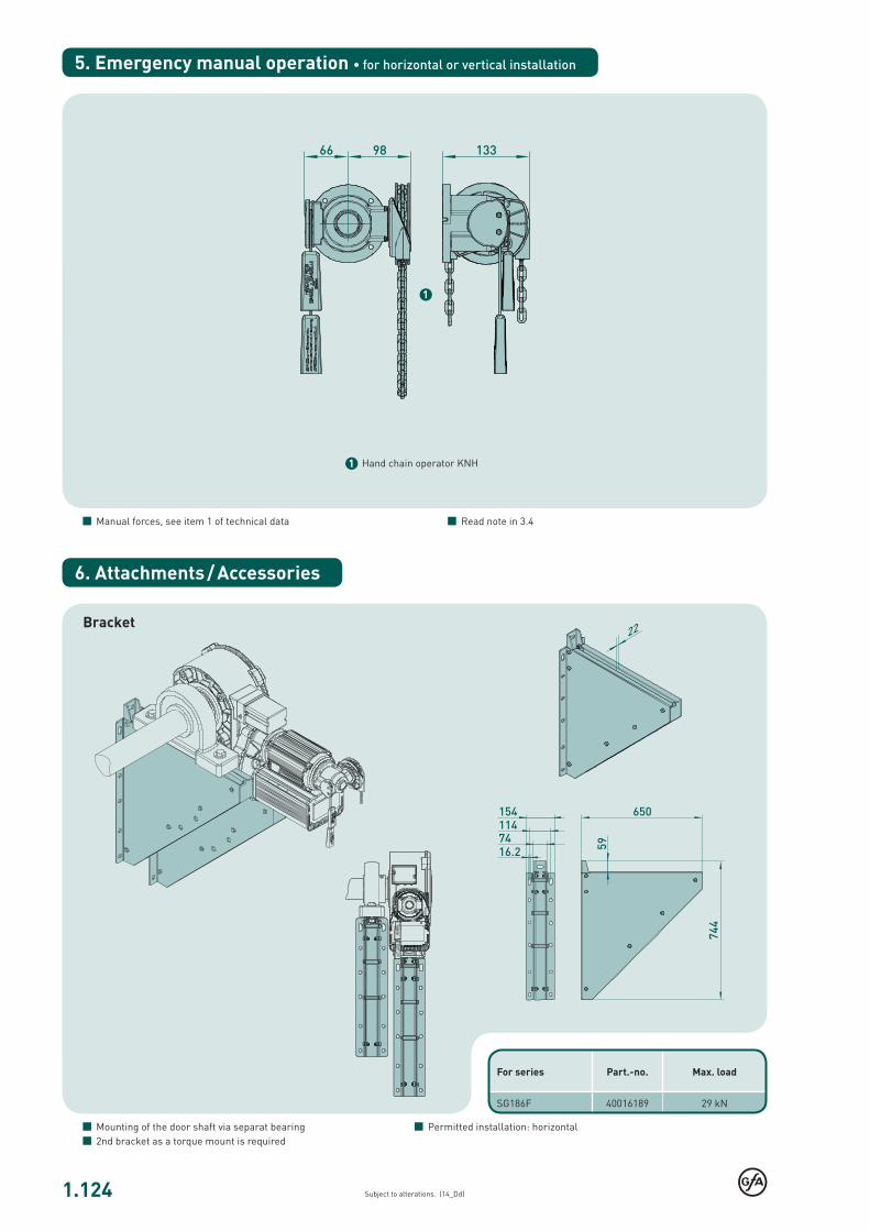
SG186F 40016189 29 kN
1
Subject to alterations. (14_Dd)
1 Hand chain operator KNH
Permitted installation: horizontal
Bracket
Mounting of the door shaft via separat bearing 2nd bracket as a torque mount is required
Manual forces, see item 1 of technical data Read note in 3.4
For series Part.-no. Max. load
5. Emergency manual operation • for horizontal or vertical installation
6. Attachments / Accessories


