“BABES–BOLYAI” UNIVERSITY
CLUJ-NAPOCA
Faculty of Chemistry and Chemical
Engineering
Victoria Goia (Maxim)
Energy conversion processes of coal and
biomass through gasification
with CO2 capture
PhD THESIS ABSTRACT
PhD Supervisor:
Prof. Univ. Paul Şerban Agachi,
Reviewers:
Prof. Dr. Ing Teodor Todincă, Polytechnic University of Timişoara
Prof. Dr. Ing Grigore Bozga, Polytechnic University Bucharest
Conf. Dr. Ing. Călin Cristian Cormoş, Universitatea Babeş-Bolyai, Cluj-Napoca
Date of public support: December 16, 2011
2
CONTENTS
MOTIVATION AND OBJECTIVES OF THE THESIS
1. INTRODUCTION
1.1. HISTORY OF GASIFICATION PROCESS AND IGCC TECHNOLOGY
1.2. THE CURRENT STATE OF KNOWLEDGE
1.3. THE IMPORTANCE OF CO2 CAPTURES
2. FEEDSTOCK
2.1. SOLID FOSSIL FUELS
2.2. RENEWABLE ENERGY RESOURCES
2.3. COMPOSITION AND PROPERTIES OF FUELS
2.3.1. Fuel analysis
2.3.2. Calorific value
2.3.3. Ash properties
3. COAL GASIFICATION. GASIFICATION REACTORS
3.1. GASIFICATION
3.1.1. Chemical reactions
3.1.2. Thermodynamics of Gasifications
3.1.3. Kinetics of Gasifications
3.2. GASIFICATION REACTORS
3.2.1. Moving-bed reactors
3.2.1.1. Lurgi reactor
3.2.1.2. British Gas Lurgi reactor (BGL)
3.2.2. Fluidized-bed reactors
3.2.2.1. Winkler reactor
3.2.2.2. High Temperature Winkler - reactor (HTW)
3.2.3. Entrained-flow reactors
3.2.3.1. Siemens reactor
3.2.3.2. Shell and Prenflo reactors
3.2.3.3. ConocoPhillips E-Gas reactor
3.2.3.4. GE-Texaco reactor
3.3. EVALUATION CRITERIA OF GASIFICATION REACTORS
4. IGCC TECHNOLOGY
4.1. IGCC TECHNOLOGY PRESENTATION
4.2. TSYNGAS TREATMENT AND PURIFICATION
4.2.1. Water–gas shift conversion
3
4.2.2. Acid gas removal
4.2.3. CO2 conditioning, compression and storage
4.2.4. Hydrogen Purification
4.3. ELECTRICITY GENERATION ISLAND
4.3.1. Combined cycle
4.3.2. Environmental impact
5. PYROLYSIS PRETREATMENT OF BIOMASS
5.1. INTRODUCTION
5.2. PYROLYSIS PROCESSES
5.2.1 The composition and use of pyrolysis products
5.2.2. Kinetics of Pyrolysis
6. IGCC PLANT ASSESSMENT
6.1. MULTI-CRITERIA ANALYSIS OF GASIFICATION REACTORS
6.2. GENERAL PRESENTATION OF IGCC PLANT
6.3. CASE STUDY: IGCC PLANT PERFORMANCE ANALYSIS USING DIFFERENT GASIFICATION TECHNOLOGIES
6.4. CASE STUDY: IGCC PLANT PERFORMANCE ANALYSIS WITH AND WITHOUT CO2 CAPTURE
6.5. CASE STUDY: IGCC PLANT PERFORMANCE ANALYSIS FOR ELECTRICITY AND HYDROGEN CO-GENERATION WITH CCS
6.6. CASE STUDY: IGCC PLANT PERFORMANCE ANALYSIS FOR CO-GASIFICATION OF COAL WITH BIOMASS AND WASTE
6.7. CONCLUSIONS
7. PYROLYSIS PRETREATMENT OF BIOMASS FOR AN IGCC PLANT
7.1. EQUIPMENT AND MATERIALS
7.2. INFLUENCE OF TEMPERATURE AND HEATING RATE ON PYROLYSIS PROCESS
7.2.1. Influence of temperature on pyrolysis process
7.2.2. Influence of heating rate on pyrolysis process
7.2.3. Influence of pyrolysis temperature on energy efficiency
7.3. CASE STUDY: THE USE OF PYROLYSIS PRODUCTS IN AN IGCC PLANT
7.4. CONCLUSIONS
8. CONCLUSIONS
9. PERSONAL APPROACH
REFERENCES
LIST OF PUBLICATIONS
LIST OF ABBREVIATIONS
LIST OF FIGURES
LIST OF TABLES

4
APPENDIXES
APPENDICS I. CHARACTERISTICS OF FEEDSTOCKS
APPENDICS II. EXPERIMENTAL DATA FOR PYROLYSIS PRODUCTS AT 250-300 ° C
Keywords:
Gasification
Energy
Carbon Capture
Renewable energy resources
5
Motivation and objectives of the thesis
In order to limit the climate change, carbon dioxide emissions must be reduced by
capturing and storing it. This is possible for electricity generation through gasification of
solid fossil fuels, using an IGCC plant with CO2 capture.
The continuous increase in the price of fossil fuels and also the increased interest
in global environmental protection, make biofuel production to grow rapidly. Currently,
an estimated global potential of biomass energy is large enough to meet global energy
demand. Although the European Union wants a swift transition from coal to biomass, for
short and medium term, coal will remain the main source of electricity generation.
Biomass gasification using existing reactors in IGCC plants it is difficult because
of biomass properties. Therefore direct gasification of biomass is not the best option,
taking into account existing commercial reactors. Worldwide, energy generation from
biomass is growing and gasification reactors are developed for biomass conversion.
This thesis presents an IGCC plant for electricity and hydrogen co-generation
with carbon capture, which can process both coal (with or without the addition of
biomass or waste) and biomass pyrolysis products. This concept is very promising, since
the plant can run on coal with or without addition of renewable energy resources in this
transition period from coal to biomass and on biomass pyrolysis products, with no further
investment in research and development of novel gasification reactors. In this context this
thesis is aligned with the highest level of energy research and utilization of renewable
energy resources.
The main objective of this thesis is to investigate innovative ways of converting
coal, waste and biomass into energy vectors (electricity and hydrogen), through
gasification with carbon capture.
The thesis aims at achieving the following objectives:
Establishing of technical characteristics of IGCC plant for electricity and
hydrogen co-generation with carbon dioxide capture;
6
Gasification technology assessment and draw up a multi-criteria analysis, in
order to narrow the range of gasification reactors that will be simulated in an
IGCC plant with CO2 capture. The choice of the four most promising options
for electricity and hydrogen co-generation with carbon dioxide capture;
Mathematical modeling and simulation of IGCC scheme using the four
chosen gasification technologies, using coal as feedstock. Results evaluation
results and choosing the right options for the studied installation;
Mathematical modeling and simulation of IGCC scheme without carbon
capture and comparison with the case when the carbon dioxide is captured
Evaluation of IGCC plant flexibility to co-generate electricity and hydrogen
while capturing carbon dioxide, depending on the electricity demand;
Investigation of co-gasification processes of coal with biomass or waste.
Mathematical modeling and simulation of co-gasification systems,
performance evaluation and comparison with the case when is used only coal
as feedstock;
Proposal of an innovative and efficient method for biomass conversion into
electricity using biomass pyrolysis products in an IGCC plant.
7
1. INTRODUCTION
Gasification is a process by which solid fossil fuels are converted into a fuel gas,
synthesis gas (mainly a mixture of carbon monoxide and hydrogen), and is one of the
oldest industrial processes for energy conversion. Generally gasification process involves
the reaction of solid fuel with an oxidizing agent (air or oxygen) in the presence of
moderator (steam) at an elevated temperature from 1200 to 1500 ° C resulting syngas
which is used for power generation or as raw material for other substances synthesis such
as methanol, urea, ammonia, etc. [1].
Fundamental principles of electricity generation were discovered in the years 1820
- 1830 by british scientist Michael Faraday. His method consists in generating energy by
moving a wire loop or copper disc between the poles of a magnet, this method being still
used today [2].
Centralized energy production became possible when it was found that AC power
lines can transport electricity at very low cost on large distances. Since 1881 began
generating centralized electricity. The first power plants were based on water or coal. For
power generation are used as fuels: coal (44.9%), gas (23.4%), nuclear fuel (20.3%),
water (6.9%), oil (1%) and other energy sources (wind, solar, geothermal) [3,4].
In order to limit the climate change, carbon dioxide emissions must be reduced by
capturing and storing it. This is possible for electricity generation through gasification of
solid fossil fuels, using an IGCC plant with CO2 capture.
IGCC technology is very important in coal power generation and environmental
protection because it has many advantages compared to classical technology used in
steam power plants based on coal or lignite to generate steam which is then expanded in a
steam turbine to produce electricity. The first advantage concerns the significantly lower
environmental impact of IGCC technology. Another advantage is related to the flexibility
of IGCC technology to produce various energy vectors according to the demand at a
time, leading to higher energy and economic efficiency. Another important factor is that
IGCC technology allows the capture of carbon dioxide (pre-combustion capture) at lower
costs and higher efficiency than for capture from flue gas (post-combustion capture).

8
IGCC technology is becoming more widespread, and in recent years more and
more gas turbines manufactured by the largest manufacturers in the field (Alstom,
Siemens, General Electric, Mitsubishi) have been adapted to be used with syngas.
9
2. FEEDSTOCK
Coal is the oldest known fossil fuel use. Coal can be defined as a sedimentary
brown-black rock with combustible properties, formed by the slow degradation of
vegetation. Over millions of years vegetation remnants have suffered a slow process of
carbonization, resulting in different sorts of coal, peat is the youngest and oldest
anthracite coal [1.4 to 6].
Biomass is the first form of energy used by humans, with the fire discovery.
Biomass is the most abundant renewable resource on the planet, including all organic
matter produced by the metabolic processes of living organisms. Biomass is not a
commonly used industrial fuel; a rate of 15-20% of the total fuel is represented by
biomass and is being used mainly for heating and domestic use. Biomass as a fuel has a
major advantage over other renewable energy resources: can be used as liquid, gaseous
and solid for power generation [1].
Waste as raw material for gasification cover a wide range of materials, both solids
and liquids. The European Union has grown increasingly in recent years and with it the
amount of waste produced. According to European Environment Agency, the European
Union annually produces 1.3 billion tonnes of waste, of which about 40 million tonnes
are hazardous waste and for every man about 3.5 tonnes of waste annually. At these
quantities are added 700 million tonnes of agricultural waste. Treatment and disposal of
all such waste without harming the environment becomes a major problem [7].
European Commission encourages the use of renewable resources for electricity
generation both to reduce dependence on oil and coal and to reduce emissions of
greenhouse gases. Biomass is a renewable resource with almost zero CO2 emissions
because it absorbs CO2 from the atmosphere is formed, so when burned does not
contribute to global CO2 emissions. However when biomass is used as fuel, some CO2
emissions are correlated with cultivation and its processing [7].
10
3. COAL GASIFICATION. GASIFICATION REACTORS
3.1. Gasification
During the gasification process a series of chemical reactions take place [1, 8,10]:
Combustion reactions
(3.1)
(3.2)
(3.3)
Boudouard reaction
(3.4)
Water-gas reaction
(3.5)
Methanation reaction
(3.6)
(3.7)
CO shift reaction
(3.8)
Pyrolysis reactions
(3.9)
Fossil fuels used in gasification contain in addition to carbon, oxygen and
hydrogen and other elements such as sulfur, nitrogen or halogens (mainly chlorine).
These components also changes during the reactions, so that nitrogen turns into NH3 and
HCN and sulfur into H2S and COS (carbonyl sulphide). If not removed, sulfur
compounds will be emitted into the atmosphere as sulfur oxides (SOx). To avoid air
pollution with SOx, IGCC technology provides a purification step of the syngas when
11
COS is converted into H2S according to one of the following chemical reactions [1.10,
11]:
(3.10)
(3.11)
3.2. Gasification reactors
Worldwide there are more than 140 gasification plants, of which 90 are located in
the U.S. and it is estimated that by 2020 their number will increase by 70%. These plants
are based on a wide range of reactors that can be classified into three categories [1, 5, 9,
11]:
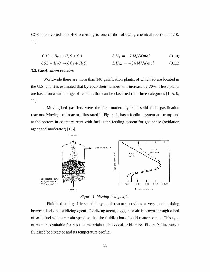
- Moving-bed gasifiers were the first modern type of solid fuels gasification
reactors. Moving-bed reactor, illustrated in Figure 1, has a feeding system at the top and
at the bottom in countercurrent with fuel is the feeding system for gas phase (oxidation
agent and moderator) [1,5].
Figure 1. Moving-bed gasifier
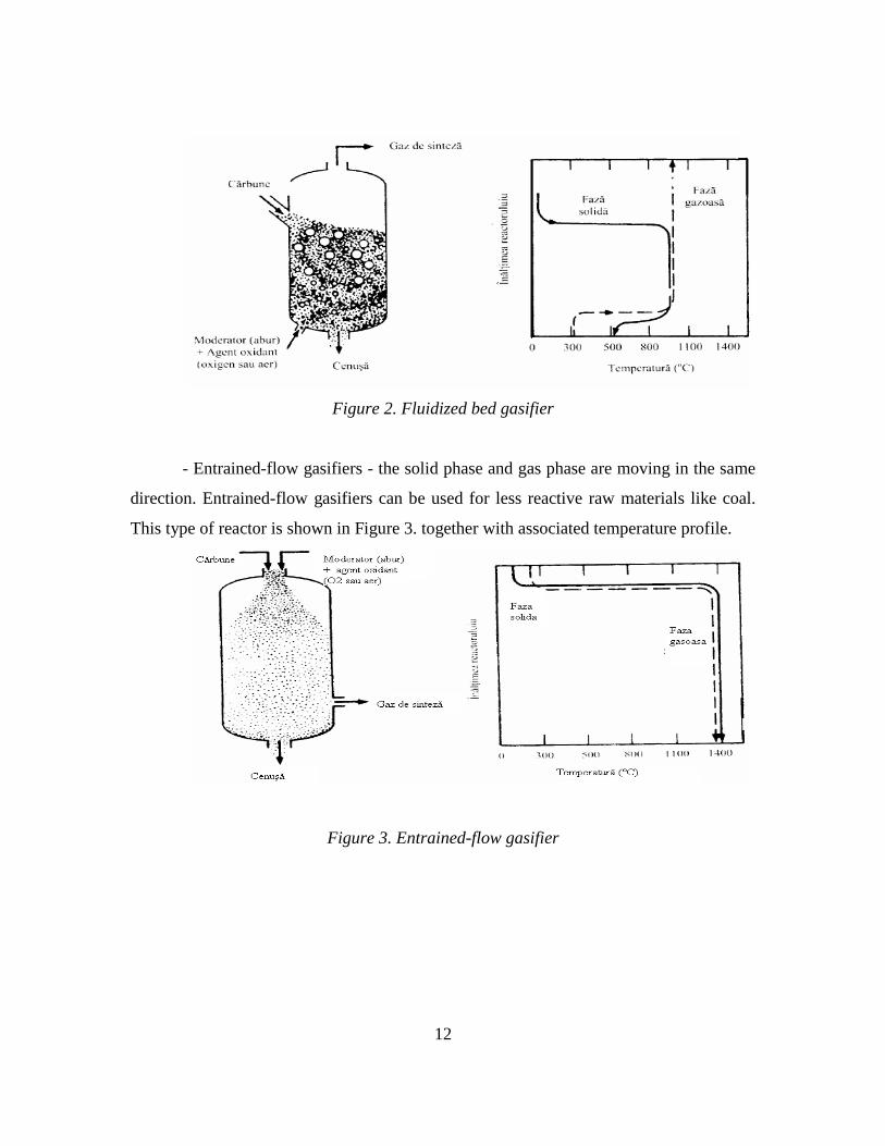
- Fluidized-bed gasifiers - this type of reactor provides a very good mixing
between fuel and oxidizing agent. Oxidizing agent, oxygen or air is blown through a bed
of solid fuel with a certain speed so that the fluidization of solid matter occurs. This type
of reactor is suitable for reactive materials such as coal or biomass. Figure 2 illustrates a
fluidized bed reactor and its temperature profile.
12
Figure 2. Fluidized bed gasifier
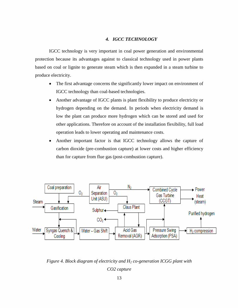
- Entrained-flow gasifiers - the solid phase and gas phase are moving in the same
direction. Entrained-flow gasifiers can be used for less reactive raw materials like coal.
This type of reactor is shown in Figure 3. together with associated temperature profile.
Figure 3. Entrained-flow gasifier
13
4. IGCC TECHNOLOGY
IGCC technology is very important in coal power generation and environmental
protection because its advantages against to classical technology used in power plants
based on coal or lignite to generate steam which is then expanded in a steam turbine to
produce electricity.
The first advantage concerns the significantly lower impact on environment of
IGCC technology than coal-based technologies.
Another advantage of IGCC plants is plant flexibility to produce electricity or
hydrogen depending on the demand. In periods when electricity demand is
low the plant can produce more hydrogen which can be stored and used for
other applications. Therefore on account of the installation flexibility, full load
operation leads to lower operating and maintenance costs.
Another important factor is that IGCC technology allows the capture of
carbon dioxide (pre-combustion capture) at lower costs and higher efficiency
than for capture from flue gas (post-combustion capture).
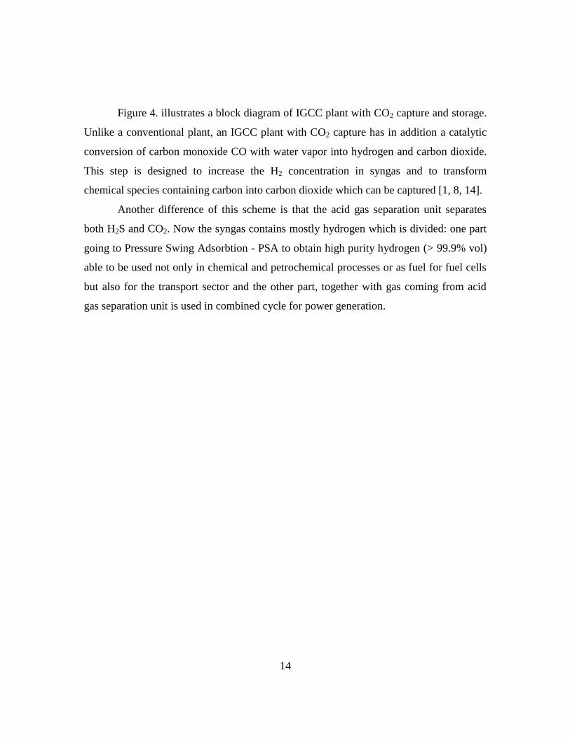
Figure 4. Block diagram of electricity and H2 co-generation ICGG plant with
CO2 capture
14
Figure 4. illustrates a block diagram of IGCC plant with CO2 capture and storage.
Unlike a conventional plant, an IGCC plant with CO2 capture has in addition a catalytic
conversion of carbon monoxide CO with water vapor into hydrogen and carbon dioxide.
This step is designed to increase the H2 concentration in syngas and to transform
chemical species containing carbon into carbon dioxide which can be captured [1, 8, 14].
Another difference of this scheme is that the acid gas separation unit separates
both H2S and CO2. Now the syngas contains mostly hydrogen which is divided: one part
going to Pressure Swing Adsorbtion - PSA to obtain high purity hydrogen (> 99.9% vol)
able to be used not only in chemical and petrochemical processes or as fuel for fuel cells
but also for the transport sector and the other part, together with gas coming from acid
gas separation unit is used in combined cycle for power generation.
15
5. PYROLYSIS PRETREATMENT OF BIOMASS
Biomass is a renewable energy resource, which includes organic matter formed by
photosynthesis. The most important renewable fuel is wood, but trees are too valuable to
be burned, but residues from wood processing industry (e.g. sawdust), could be a very
valuable feedstock. Other sorts of biomass that can be used as fuels are agricultural
residues such as wheat straw, corn stalks, rice husks, coconut etc. Fossil fuels (e.g. oil,
coal, lignite) are also derived from plant species with the difference that was formed
during millions of years. Worldwide biomass has always been a major source of energy
since the beginning of civilization. In under development countries and rural areas woody
biomass and agriculture residues still represent a significant proportion of feedstock for
thermal energy supply [16-18].
Gasification of biomass in existent gasification reactors is difficult, because of the
properties of biomass. It is known that to have high efficiency gasification process is
necessary that the ratio O / C of the fuel to be as small as possible, like in the case of
coal, but biomass is a fuel that has high O/C ratio. Another problem is the feeding of
existing gasification reactors with biomass, which should be shredded at 100 mm, which
means an energy penalty of about 20%. Thus the direct gasification of biomass is not the
best option, taking into account existing commercial reactors at this time. But an
attractive alternative is the pretreatment of biomass through pyrolysis at low temperature
before being gasified.
Pyrolysis is the thermo chemical decomposition of solid fuels (biomass, waste,
fossil fuels) in the absence of oxygen with production of chemicals, heat or energy.
Pyrolysis is the first step in all other thermo conversion technologies such as combustion
and gasification. The process takes place at relatively low temperatures (300-800 ° C)
compared to 900-1500 ° C for gasification [11, 19-21].
16
6. IGCC PLANT ASSESSMENT
Multi-criteria analysis of gasification reactors
The aim of this multi-criteria analysis is to narrow the range of gasification
reactors that will be simulated in an IGCC plant with CO2 capture. Using the data
obtained from simulations a selection regarding the gasification reactor can be made,
which will be used in a co-generation of electricity and hydrogen IGCC plant with CO2
capture and which can process a wide range of feedstocks (e.g. coal, coal in addition to
various renewable energy resources, biomass pyrolysis products).
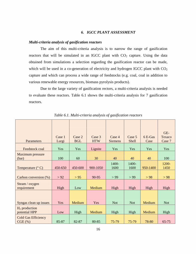
Due to the large variety of gasification rectors, a multi-criteria analysis is needed
to evaluate these reactors. Table 6.1 shows the multi-criteria analysis for 7 gasification
reactors.
Table 6.1. Multi-criteria analysis of gasification reactors
Parameters
Case 1
Lurgi
Case 4
Siemens
Case 5
Shell
6 E-Gas
Case
GE-
Texaco
Case 7
Case 2
BGL
Case 3
HTW
Feedstock coal Yes Yes Lignite Yes Yes Yes Yes
Maximum pressure
(bar) 100 60 30 40 40 40 100
Temperature (° C) 450-650 450-600 900-1050
1400-
1600
1400-
1600 950-1400
1200-
1450
Carbon conversion (%) > 92 > 95 90-95 > 99 > 99 > 98 > 98
Steam / oxygen
requirement High Low Medium High High High High
Syngas clean up issues Yes Medium Yes Not Not Medium Not
H2 production
potential HPP Low High Medium High High Medium High
Cold Gas Efficiency
CGE (%) 85-87 82-87 80-85 75-79 75-79 78-80 65-75
17
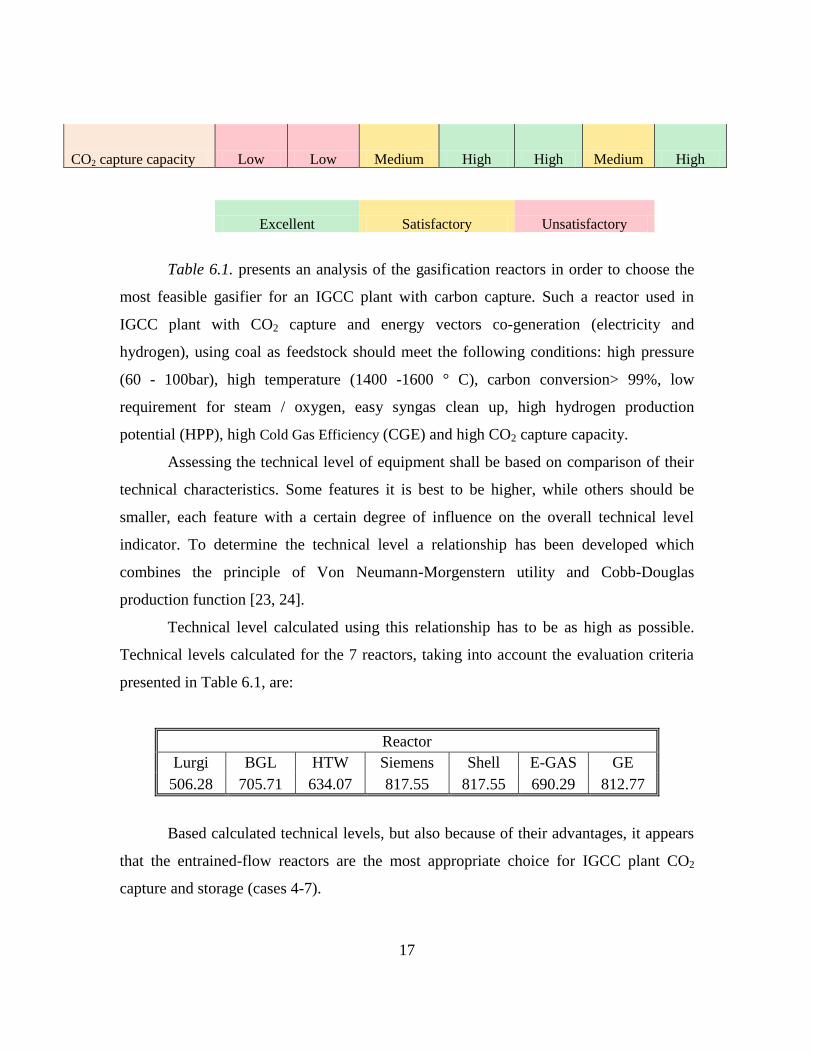
CO2 capture capacity Low Low Medium High High Medium High
Excellent Satisfactory Unsatisfactory
Table 6.1. presents an analysis of the gasification reactors in order to choose the
most feasible gasifier for an IGCC plant with carbon capture. Such a reactor used in
IGCC plant with CO2 capture and energy vectors co-generation (electricity and
hydrogen), using coal as feedstock should meet the following conditions: high pressure
(60 - 100bar), high temperature (1400 -1600 ° C), carbon conversion> 99%, low
requirement for steam / oxygen, easy syngas clean up, high hydrogen production
potential (HPP), high Cold Gas Efficiency (CGE) and high CO2 capture capacity.
Assessing the technical level of equipment shall be based on comparison of their
technical characteristics. Some features it is best to be higher, while others should be
smaller, each feature with a certain degree of influence on the overall technical level
indicator. To determine the technical level a relationship has been developed which
combines the principle of Von Neumann-Morgenstern utility and Cobb-Douglas
production function [23, 24].
Technical level calculated using this relationship has to be as high as possible.
Technical levels calculated for the 7 reactors, taking into account the evaluation criteria
presented in Table 6.1, are:
Reactor
Lurgi BGL HTW Siemens Shell E-GAS GE
506.28 705.71 634.07 817.55 817.55 690.29 812.77
Based calculated technical levels, but also because of their advantages, it appears
that the entrained-flow reactors are the most appropriate choice for IGCC plant CO2
capture and storage (cases 4-7).
18
The purpose of this analysis was to narrow the range of reactors to be simulated in
an IGCC plant with CO2 capture. Based on multi-criteria analysis performed for energy
vectors poly-generation IGCC plant with CO2 capture and storage were chosen as most
suitable reactors the entrained flow gasifiers.
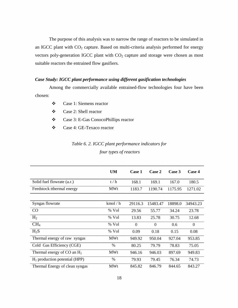
Case Study: IGCC plant performance using different gasification technologies
Among the commercially available entrained-flow technologies four have been
chosen:
Case 1: Siemens reactor
Case 2: Shell reactor
Case 3: E-Gas ConocoPhillips reactor
Case 4: GE-Texaco reactor
Table 6. 2. IGCC plant performance indicators for
four types of reactors
UM Case 1 Case 2 Case 3 Case 4
Solid fuel flowrate (a.r.) t / h 168.1 169.1 167.0 180.5
Feedstock tthermal energy MWt 1183.7 1190.74 1175.95 1271.02
Syngas flowrate kmol / h 29116.3 15483.47 18898.0 34943.23
CO % Vol 29.56 55.77 34.24 23.78
H2 % Vol 13.83 25.78 30.75 12.68
CH4 % Vol 0 0 0.6 0
H2S % Vol 0.09 0.18 0.15 0.08
Thermal energy of raw syngas MWt 949.92 950.04 927.04 953.85
Cold Gas Efficiency (CGE) % 80.25 79.79 78.83 75.05
Thermal energy of CO an H2 MWt 946.16 946.03 897.69 949.83
H2 production potential (HPP) % 79.93 79.45 76.34 74.73
Thermal Energy of clean syngas MWt 845.82 846.79 844.65 843.27
19
Technical levels were calculated for each reactor:
Reactor
Siemens Shell E-GAS GE
313.40 297.86 216.68 282.96
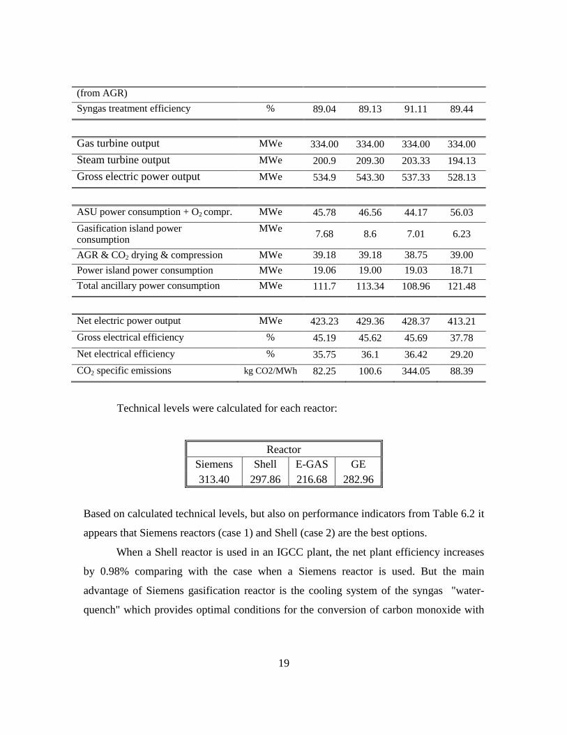
Based on calculated technical levels, but also on performance indicators from Table 6.2 it
appears that Siemens reactors (case 1) and Shell (case 2) are the best options.
When a Shell reactor is used in an IGCC plant, the net plant efficiency increases
by 0.98% comparing with the case when a Siemens reactor is used. But the main
advantage of Siemens gasification reactor is the cooling system of the syngas "water-
quench" which provides optimal conditions for the conversion of carbon monoxide with
(from AGR)
Syngas treatment efficiency % 89.04 89.13 91.11 89.44
Gas turbine output MWe 334.00 334.00 334.00 334.00
Steam turbine output MWe 200.9 209.30 203.33 194.13
Gross electric power output MWe 534.9 543.30 537.33 528.13
ASU power consumption + O2 compr. MWe 45.78 46.56 44.17 56.03
Gasification island power consumption
MWe 7.68 8.6 7.01 6.23
AGR & CO2 drying & compression MWe 39.18 39.18 38.75 39.00
Power island power consumption MWe 19.06 19.00 19.03 18.71
Total ancillary power consumption MWe 111.7 113.34 108.96 121.48
Net electric power output MWe 423.23 429.36 428.37 413.21
Gross electrical efficiency % 45.19 45.62 45.69 37.78
Net electrical efficiency % 35.75 36.1 36.42 29.20
CO2 specific emissions kg CO2/MWh 82.25 100.6 344.05 88.39
20
water vapor, a precondition to capture carbon dioxide. Another advantage is due to lower
CO2 emissions by 22% than in the Shell reactor, which means 137 tCO2/an.
Based on these considerations was chosen as best option for the considered plant
a Siemens reactor. So case studies to be further conducted in this paper will be based on
Siemens gasification technology.
Case Study: IGCC plant performance assessment with and without CO2 capture
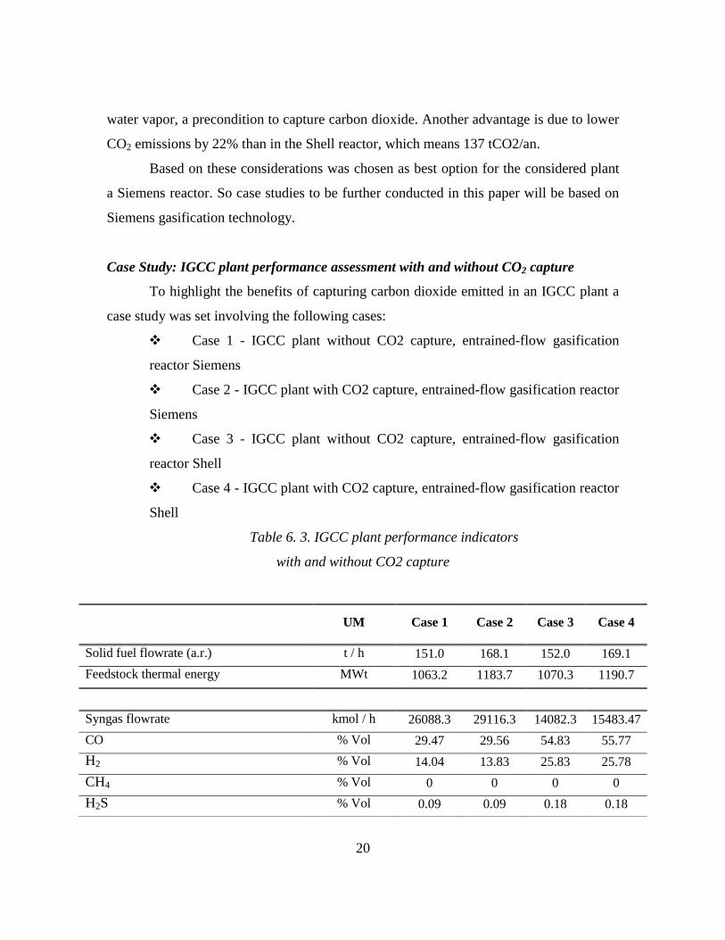
To highlight the benefits of capturing carbon dioxide emitted in an IGCC plant a
case study was set involving the following cases:
Case 1 - IGCC plant without CO2 capture, entrained-flow gasification
reactor Siemens
Case 2 - IGCC plant with CO2 capture, entrained-flow gasification reactor
Siemens
Case 3 - IGCC plant without CO2 capture, entrained-flow gasification
reactor Shell
Case 4 - IGCC plant with CO2 capture, entrained-flow gasification reactor
Shell
Table 6. 3. IGCC plant performance indicators
with and without CO2 capture
UM Case 1 Case 2 Case 3 Case 4
Solid fuel flowrate (a.r.) t / h 151.0 168.1 152.0 169.1
Feedstock thermal energy MWt 1063.2 1183.7 1070.3 1190.7
Syngas flowrate kmol / h 26088.3 29116.3 14082.3 15483.47
CO % Vol 29.47 29.56 54.83 55.77
H2 % Vol 14.04 13.83 25.83 25.78
CH4 % Vol 0 0 0 0
H2S % Vol 0.09 0.09 0.18 0.18

21
Calculated technical levels for each case are:
Reactor
Siemens
without
capture
Siemens
with
capture
Shell
without
capture
Shell with
capture
176.59 313.40 177.68 297.86
It may be noted that in cases without CO2 capture the net efficiency is higher by
12.52% for Siemens reactor and by 13.38% for the Shell reactor. Decrease in net
efficiency of the plant in cases where CO2 was captured is due to significant increase in
energy consumption of AGR and CO2 compression. CO2 emissions were drastically
reduced in cases where the carbon dioxide was captured.
Thermal energy of raw syngas MWt 853.22 949.92 854.13 950.04
Cold Gas Efficiency (CGE) % 80.24 80.25 79.80 79.79
Thermal Energy of clean syngas (from AGR)
MWt 849.41 845.82 850.51 843.27
Syngas treatment efficiency % 99.55 89.04 99.57 89.44
Gas turbine output MWe 334 334 334 334.00
Steam turbine output MWe 186.65 200.9 200.89 209.30
Gross electric power output MWe 520.65 534.9 534.89 543.30
ASU power consumption + O2 compr. MWe 41.12 45.78 40.19 46.56
Gasification island power consumption MWe 6.81 7.68 7.87 8.6
AGR & CO2 drying & compression MWe 6.01 39.18 6.04 39.18
Power island power consumption MWe 19.17 19.06 19.24 19.00
Total ancillary power consumption MWe 73.11 111.7 73.34 113.34
Net electric power output MWe 447.54 423.23 461.55 429.96
Gross electrical efficiency % 48.96 45.19 49.97 45.62
Net electrical efficiency % 42.09 35.75 43.12 36.1
CO2 specific emissions kg CO2/MWh 853.44 82.25 843.78 100.6
22
IGCC technology has other advantages in terms of environmental impact: lower
emissions of SOx and NOx, but also the possibility of using inferior coal as feedstock,
but also biomass or waste. [25-27].
Case Study: IGCC plant performance assessment for electricity and hydrogen co-
generation with CO2 capture
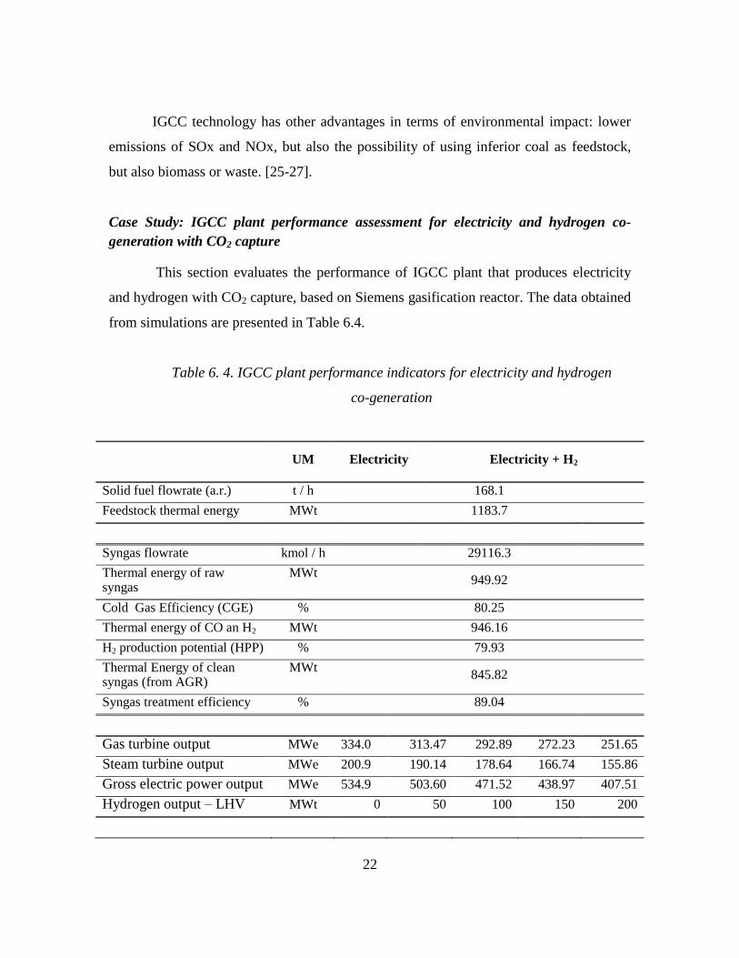
This section evaluates the performance of IGCC plant that produces electricity
and hydrogen with CO2 capture, based on Siemens gasification reactor. The data obtained
from simulations are presented in Table 6.4.
Table 6. 4. IGCC plant performance indicators for electricity and hydrogen
co-generation
UM Electricity Electricity + H2
Solid fuel flowrate (a.r.) t / h 168.1
Feedstock thermal energy MWt 1183.7
Syngas flowrate kmol / h 29116.3
Thermal energy of raw syngas
MWt 949.92
Cold Gas Efficiency (CGE) % 80.25
Thermal energy of CO an H2 MWt 946.16
H2 production potential (HPP) % 79.93
Thermal Energy of clean syngas (from AGR)
MWt 845.82
Syngas treatment efficiency % 89.04
Gas turbine output MWe 334.0 313.47 292.89 272.23 251.65
Steam turbine output MWe 200.9 190.14 178.64 166.74 155.86
Gross electric power output MWe 534.9 503.60 471.52 438.97 407.51
Hydrogen output – LHV MWt 0 50 100 150 200
23
From this study it can be seen that the combined efficiency of the process
increases with increasing the amount of hydrogen generated. Carbon dioxide emissions
decreases with increasing the amount of hydrogen generated. Because of the flexibility
facility to produce electricity and hydrogen according to the request at a time, the
cumulative efficiency is greater for co-generation and the quantity of carbon dioxide is
reduced, the electricity and hydrogen co-generation IGCC plant is a very attractive
option.
Case Study: IGCC plant performance assessment for co-gasification of coal with
biomass and waste
This study evaluates the use of coal with or without addition of biomass / waste
in gasification process in order to produce syngas for electricity generation.
Case 1: coal
Case 2: coal in addition with Sawdust SWD
Case 3: coal in addition with sewage sludge SWG
Case 4: coal in addition with meat and bone meal MBM
Total ancillary power consumption
MWe 111.7 111.59 111.57 111.55 111.51
Net electric power output MWe 423.23 392.01 359.95 327.42 296.00
Gross electrical efficiency % 45.19 42.54 39.83 37.08 34.42
Net electrical efficiency % 35.75 33.11 30.40 27.66 25.00
Hydrogen efficiency % 0 4.22 8.44 12.67 16.89
Cumulative efficiency % 35.75 37.27 38.83 40.32 41.84
CO2 specific emissions kg CO2/MWh 82.25 78.20 75.15 72.00 69.12
24
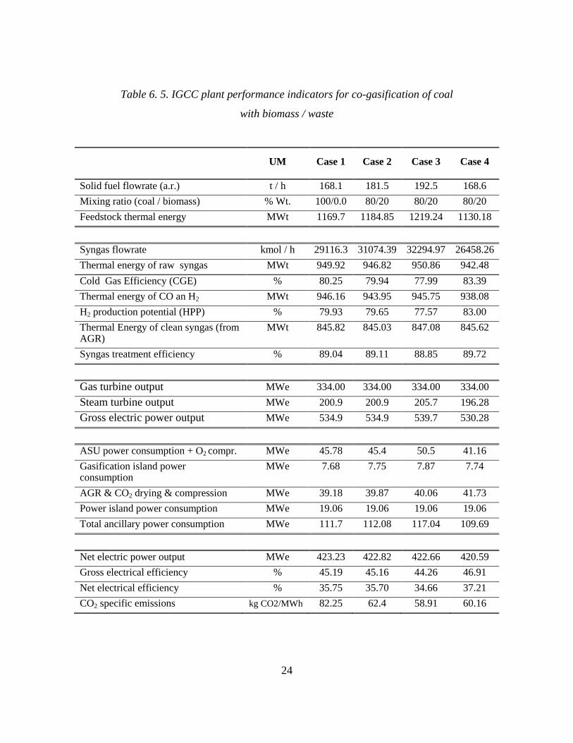
Table 6. 5. IGCC plant performance indicators for co-gasification of coal
with biomass / waste
UM Case 1 Case 2 Case 3 Case 4
Solid fuel flowrate (a.r.) t / h 168.1 181.5 192.5 168.6
Mixing ratio (coal / biomass) % Wt. 100/0.0 80/20 80/20 80/20
Feedstock thermal energy MWt 1169.7 1184.85 1219.24 1130.18
Syngas flowrate kmol / h 29116.3 31074.39 32294.97 26458.26
Thermal energy of raw syngas MWt 949.92 946.82 950.86 942.48
Cold Gas Efficiency (CGE) % 80.25 79.94 77.99 83.39
Thermal energy of CO an H2 MWt 946.16 943.95 945.75 938.08
H2 production potential (HPP) % 79.93 79.65 77.57 83.00
Thermal Energy of clean syngas (from AGR)
MWt 845.82 845.03 847.08 845.62
Syngas treatment efficiency % 89.04 89.11 88.85 89.72
Gas turbine output MWe 334.00 334.00 334.00 334.00
Steam turbine output MWe 200.9 200.9 205.7 196.28
Gross electric power output MWe 534.9 534.9 539.7 530.28
ASU power consumption + O2 compr. MWe 45.78 45.4 50.5 41.16
Gasification island power consumption
MWe 7.68 7.75 7.87 7.74
AGR & CO2 drying & compression MWe 39.18 39.87 40.06 41.73
Power island power consumption MWe 19.06 19.06 19.06 19.06
Total ancillary power consumption MWe 111.7 112.08 117.04 109.69
Net electric power output MWe 423.23 422.82 422.66 420.59
Gross electrical efficiency % 45.19 45.16 44.26 46.91
Net electrical efficiency % 35.75 35.70 34.66 37.21
CO2 specific emissions kg CO2/MWh 82.25 62.4 58.91 60.16
25
As can be noticed in Table 6.5. all four cases evaluated have a net electric power
output of about 420 MW and plant net efficiency between 34% and 37%. For the same
power output of about 420 MW is required a different amount of feedstock, according to
its calorific value.
Calculated technical levels for each case are:
Feedstock
Coal Coal with SWD Coal with SWG Coal with MBM
313.40 335.07 333.13 348.87
Based on key performance indicators and calculated technical levels it appears
that the best mixtures are coal in addition with sawdust and coal in addition with meat
and bone meal.
Conclusively IGCC plant developed in this thesis is flexible in terms of feedstock
supply can be fed with both coal and coal in addition with renewable energy resources
(biomass) or solid wastes. In this context, this flexible plant is a solution that can ensure
the transition from an economy based almost entirely on coal to an economy based on
renewable energy resources.
26
7. PYROLYSIS PRETREATMENT OF BIOMASS
FOR AN IGCC PLANT
Coal gasification technology is a mature technology without issues, but biomass
gasification due to its proprieties significant large problems. IGCC demonstrative plants
which used biomass feedstock have been set up, such as the one in Värnamo, Sweden
(1991 - 1993). These plants ran for a short period of time, aiming to demonstrate the
technical possibility of biomass gasification, but biomass fueled IGCC plants are not yet
efficient and optimized, being under continuous research and development.
This study aims to demonstrate the advantages pyrolysis pretreatment of biomass
before gasification, and investigates the possibility to generate electricity in an IGCC
plant using as feedstock biomass pyrolysis products.
Pyrolysis products were analyzed by different methods:
- Solid analysis by proximate/ultimate analysis
- Permanent gases removed by argon purge gas, collected in gasbag and
analyzed by (GC),
- Liquid products analysis by HPLC.
178 experiments were performed at temperatures between 250 ° C and 700 ° C
and heating rates between 5-80 ° C / min. As feedstocks were used 14 types of biomass
with different humidity, characteristics of the feedstocks used are presented in Appendix
I.
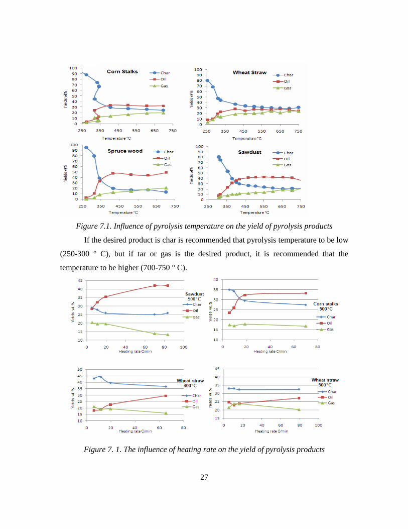
Product composition and yield are affected by pyrolysis temperature. Figure 7.2.
shows the effect of temperature on pyrolysis products distribution for the four types of
biomass selected for example, at temperatures between 250 ° C and 700 ° C in a fixed
bed reactor.
27
Figure 7.1. Influence of pyrolysis temperature on the yield of pyrolysis products
If the desired product is char is recommended that pyrolysis temperature to be low
(250-300 ° C), but if tar or gas is the desired product, it is recommended that the
temperature to be higher (700-750 ° C).
Figure 7. 1. The influence of heating rate on the yield of pyrolysis products
28
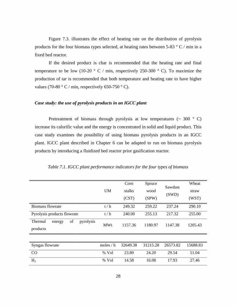
Figure 7.3. illustrates the effect of heating rate on the distribution of pyrolysis
products for the four biomass types selected, at heating rates between 5-83 ° C / min in a
fixed bed reactor.
If the desired product is char is recommended that the heating rate and final
temperature to be low (10-20 ° C / min, respectively 250-300 ° C). To maximize the
production of tar is recommended that both temperature and heating rate to have higher
values (70-80 ° C / min, respectively 650-750 ° C).
Case study: the use of pyrolysis products in an IGCC plant
Pretreatment of biomass through pyrolysis at low temperatures (~ 300 ° C)
increase its calorific value and the energy is concentrated in solid and liquid product. This
case study examines the possibility of using biomass pyrolysis products in an IGCC
plant. IGCC plant described in Chapter 6 can be adapted to run on biomass pyrolysis
products by introducing a fluidized bed reactor prior gasification reactor.
Table 7.1. IGCC plant performance indicators for the four types of biomass
UM
Corn
stalks
(CST)
Spruce
wood
(SPW)
Sawdust
(SWD)
Wheat
straw
(WST)
Biomass flowrate t / h 249.32 259.22 237.24 290.10
Pyrolysis products flowrate t / h 240.00 255.13 217.32 255.00
Thermal energy of pyrolysis
products MWt 1157.36 1180.97 1147.38 1205.43
Syngas flowrate moles / h 32649.38 31215.28 26573.82 15688.83
CO % Vol 23.80 24.20 29.54 51.04
H2 % Vol 14.58 16.08 17.93 27.46
29
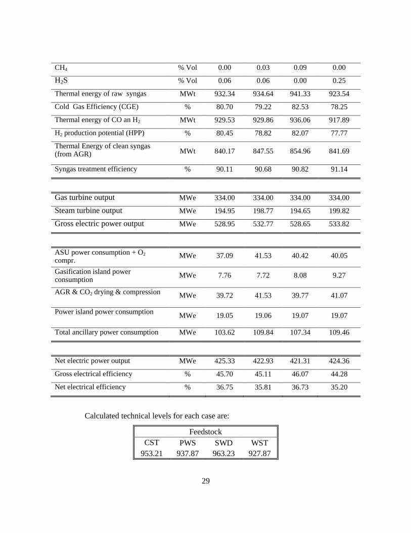
CH4 % Vol 0.00 0.03 0.09 0.00
H2S % Vol 0.06 0.06 0.00 0.25
Thermal energy of raw syngas MWt 932.34 934.64 941.33 923.54
Cold Gas Efficiency (CGE) % 80.70 79.22 82.53 78.25
Thermal energy of CO an H2 MWt 929.53 929.86 936.06 917.89
H2 production potential (HPP) % 80.45 78.82 82.07 77.77
Thermal Energy of clean syngas (from AGR) MWt 840.17 847.55 854.96 841.69
Syngas treatment efficiency % 90.11 90.68 90.82 91.14
Gas turbine output MWe 334.00 334.00 334.00 334.00
Steam turbine output MWe 194.95 198.77 194.65 199.82
Gross electric power output MWe 528.95 532.77 528.65 533.82
ASU power consumption + O2
compr. MWe 37.09 41.53 40.42 40.05
Gasification island power consumption
MWe 7.76 7.72 8.08 9.27
AGR & CO2 drying & compression MWe 39.72 41.53 39.77 41.07
Power island power consumption MWe 19.05 19.06 19.07 19.07
Total ancillary power consumption MWe 103.62 109.84 107.34 109.46
Net electric power output MWe 425.33 422.93 421.31 424.36
Gross electrical efficiency % 45.70 45.11 46.07 44.28
Net electrical efficiency % 36.75 35.81 36.73 35.20
Calculated technical levels for each case are:
Feedstock
CST PWS SWD WST
953.21 937.87 963.23 927.87
30
Based on calculated technical levels but also as can be seen in Table 7.2., for an
installed capacity of about 420 MW it can be said that from biomass sorts used in
simulations, the most efficient, in terms of energy efficiency and Cold Gas Efficiency
(CGE), are cases where sawdust (SWD) or corn stalks (CST) are used as feedstock.
As shown, direct use of biomass as fuel in an entrained flow gasifier has certain
technological constrains, but pretreatment of biomass through pyrolysis before being
gasified is a very attractive option. Biomass pretreatment through pyrolysis improves its
properties enabling the feeding in an entrained-flow reactor.
The IGCC plant proposed in this section provides the possibility to generate a
large amount of electricity in IGCC plant using biomass, as pyrolysis products, using a
pyrolysis reactor before the gasification reactor. Energy produced from biomass is
considered a green energy because as is burned and emits a certain amount of carbon
dioxide in the atmosphere, the same amount of carbon dioxide is absorbed by other plants
during growth.
31
8. Conclusions and personal approach
The IGCC plant proposed in this thesis is flexible in terms of electricity
generation and hydrogen according to the requirement at a time, has a very low
environmental impact compared with conventional technology and is flexible in terms of
supply raw material.
For the evaluation of the innovative energy vectors co-generation schemes with
carbon dioxide capture mathematical modeling and simulations were carried out using
specific software ChemCAD. Data obtained from the simulations led to the preparation
of case studies analyzed.
The main objective of this thesis is to investigate innovative ways of converting
coal, waste and biomass into energy vectors (electricity and hydrogen), through
gasification with carbon capture.
The IGCC plant scheme proposed in this thesis is very promising because of its
advantages:
- Plant flexibility to produce electricity and hydrogen: depending on the
demand the system has the ability to produce one of the two energy vectors;
- Plant flexibility to be fed with different feedstocks: coal, coal in addition with
biomass or waste or biomass pyrolysis products;
- No metter the feedstock used, the plant has a very low environmental impact;
- This plant is a solution that can ensure the transition from an economy based
almost entirely on coal by an economy based on renewable energy resources.
The results of this thesis contribute to the research field of energy conversion
systems and use of renewable energy resources with carbon dioxide capture by the
following additional contributions:
Detailed analysis of coal gasification processes with or without the addition of
biomass or solid waste, in order to be transformed into energy vectors (electricity
or hydrogen) with carbon dioxide capture.
Evaluation of IGCC plant flexibility to co-generate electricity and hydrogen with
carbon dioxide capture, depending on the electricity demand at a time. Thus in
32
this period of continuous development of hydrogen based applications the IGCC
plant can produce more electricity than hydrogen, and gradually as the demand
for hydrogen will increase the plant will produce more hydrogen according to
demand.
Assessment of environmental impact of the proposed IGCC schemes with carbon
capture compared with the current conventional IGCC plants without capture of
carbon dioxide.
Proofing, based on experimental data, the advantages of biomass pretreatment
through pyrolysis before being gasified.
The proposal of an efficient solution of using biomass as feedstock for electricity
generation using biomass pyrolysis products in an IGCC plant. Biomass pyrolysis
products can be used either in an IGCC plant with CO2 capture such as the one
proposed in this paper either in a conventional IGCC plant without CO2 capture.
This is possible by including a fluidized bed pyrolysis reactor before the
gasification reactor.
The IGCC concept proposed in this thesis, due to its advantages, is a promising
solution not only for short and medium term (until depletion of coal), but also for long
term it will ease the transition from an economy based almost entirely on coal to an
economy based entirely on renewable energy resources.
33
SELECTED REFERENCES
1. Higman, C., Van Der Burgt, M., 2008, Gasification Second edition, Elsevier
Science.
2. The Institution of Engineering & Technology: Michael Faraday , www.theiet.org.
3. US Environmental Protection Agency, www.epa.gov.
4. Fanchi, J.R., 2004, Energy: Tecnology and directions for the future, Elsevier.
5. Demirbas, A., 2009, Biofuels: Securing the Planet’s Future Energy Needs,
Springer-Verlag London Limited.
6. Miller, B.G., 2005, Coal Energy Systems, Elsevier Academic Press.
7. Comisia Europeană, www. ec.europa.eu.
8. Cormoş, C.C., 2008, Decarbonizarea combustibililor fosili solizi prin gazeificare,
Cluj University Press.
9. Gasification Technologies Council, 2011, www.gasification.org.
10. Basu, P., 2006, Combustion and gasification in fluidized beds, Taylor&Francis,
New York.
11. De Souza-Santos, M.L., 2004, Solid fuels combustion and gasification. Modelling,
simulation and equipment operation, Marcel Dekker, New-York.
12. Shoko, E., McLellan, B., Dicks, A.L., Diniz da Costa, J.C., 2006, Hydrogen from
coal: Production and utilisation technologies, International Journal of Coal
Geology, 65, 213– 222.
13. Emun, F., Gadalla, M., Jimenez, L., 2008, Integrated Gasification Combined
Cycle (IGCC) process simulation and optimization, Computer Aided Chemical
Engineering, 25, 1059-1064.
14. Kunze, C., Spliethoff, H., 2010, Modelling of an IGCC plant with carbon capture
for 2020, Fuel Processing Technology, 91, 934-941.
15. Massachusetts Institute of Technology Laboratory for Energy and the
Environment, Report MIT LFEE 2005-002 WP, September 2005
34
16. Ladanai, S., Winterbäch, J., 2009, Report: Global potential of sustainable
biomass for energy, Swedish University of Agricultural Sciences Department of
Energy and Technology.
17. Jaccard, M., 2005, Sustainable Fossil Fuels, Cambridge University Press.
18. Quaak, P., Knoef, H., Stassen, H., 1999, Energy from biomass, World Bank
technical paper; 422, Energy series, Library of Congress Cataloging-in-
Publication Data.
19. I.W. Smith, The combustion rates of coal chars: a review, Proceedings of the
Combustion Institute, 1045 – 1065, 1982
20. Lurgi GmbH, www.lurgi.com
21. Erasmus, H.B., van Nierop, P., 2002, Sasol: fifty years of growth, IChemE 5’th
European Gasification Conference, Noordwijk, The Netherlands.
22. Wampler, T.P., 2007, Applied pyrolysis handbook 2nd
edition, Taylor&Francis
Group New York.
23. Douglas, P.H., 1976, The Cobb-Douglas Production Function Once Again: Its
History, Its Testing, and Some New Empirical Values, Journal of Political
Economy, 84, 903-916
24. Fishburn, P.C.,Kochenberger, G.A., 1979, Two-piece von Neumann-Morgenstern
utility functions, Decision Sciences, 10, 503-18
25. Raja, A.K., Srivastava, A.P., Dwivedi, M., 2006, Power plant engineering, New
Age Interantional Limited Publishers.
26. Cormos, C.C., 2010, Evaluation of iron based chemical looping for hydrogen and
electricity co-production by gasification processwith carbon capture and storage,
International Journal of Hydrogen and Energy, 35, 2278 - 2289
27. Bhattacharya, A., Manna, D., Paul, B., Datta, A., 2011, Biomass integrated
gasification combined cycle power generation with supplementary biomass firing:
Energy and exergy based performance analysis, Energy, 36, 2599-2610.


![Chapter 2 Biomass Conversion Processes · Chapter 2 Biomass Conversion Processes Problems and Discussion Issues Heat Energy Conversion Efficiency 2.1 One tonne [1.1 tons] of dried](https://cdn.vdocuments.net/doc/165x107/5f0705517e708231d41ae6ad/chapter-2-biomass-conversion-processes-chapter-2-biomass-conversion-processes-problems.jpg)


