
01-08-2018 Im236 Page 1
ENGINE TEST SET UP
1 CYLINDR, 4 STROKE, PETROL
(Computerized)
Instruction manual
Contents
1 Description
2 Specifications
3 Installation requirements
4 Packing slip
5 Installations
6 Commissioning
7 Software
8 Troubleshooting
9 Experiments
10 Components used
11 Calculations
12Wiring &Warranty
Product Code 236

Apex Innovations
01-08-2018 Im236 Page 2
The setup consists of single cylinder, four stroke, petrol engine connected to eddy
current type dynamometer for variable loading. It is provided with necessary
equipment and instruments for combustion pressure, and crank-angle
measurements. These signals are interfaced to computer through engine indicator
for PPV diagrams. Provision is also made for interfacing airflow, fuel flow,
temperature and load measurement with computer. The setup has stand-alone
type independent panel box consisting of air box, fuel tank, manometer, fuel
measuring unit, transmitters for air and fuel flow measurements, Temperature
indicator, Load indicator and Piezo powering unit.
The setup enables study of engine performance for brake power, indicated power,
frictional power, BMEP, IMEP, brake thermal efficiency, indicated thermal
efficiency, Mechanical efficiency, volumetric efficiency, specific fuel consumption,
A/F ratio and heat balance. Labview based Engine Performance Analysis software
Package “Enginesoft” is provided for on line performance evaluation.
ENGINEDYNAMOMETER
Schematic arrangement (Performance evaluation)
Description

Apex Innovations
01-08-2018 Im236 Page 3
Product Engine test setup 1 cylinder, 4 stroke, Petrol
(Computerized)
Product code 236
Engine Engine, Make-Honda, Model -Honda GX200D QX,
Type-Single cylinder, 4 stroke Petrol, Air cooled, 4.1
KW at 3600 rpm, stroke 54 mm, bore 68 mm.
Capacity 196 cc
Dynamometer Type eddy current, water cooled with loading unit
Air box M S fabricated with orifice meter and manometer
(Orifice dia. 16 mm)
Fuel tank Capacity 15 lit with glass fuel metering column
Piezo sensor Range 5000 PSI with low noise cable
Crank angle sensor Resolution 1 Deg. with TDC pulse..
Data acquisition device NI USB-6210, 16-bit, 250kS/s.
Piezo powering unit Make-Apex, Model AX-409.
Temperature sensor Thermocouple, Type K
Temp. transmitter Type two wire, Input Thermocouple, Output 4–20 mA.
Digital voltmeter Range 0-200mV, panel mounted
Load sensor Load cell, type strain gauge, range 0-50 Kg
Load indicator Digital, Range 0-50 Kg, Supply 230VAC
Fuel flow transmitter DP transmitter, Range 0-500 mm WC
Air flow transmitter Range (-) 250 mm WC
Software “Enginesoft” Engine performance analysis software
Overall dimensions W 1800 x D 1400 x H 1500 mm
Shipping details
Gross volume 1.89m3, Gross weight 538kg, Net weight 460kg
Specifications
Apex Innovations
01-08-2018 Im236 Page 4
Electric supply
Provide 230 +/- 10 VAC, 50 Hz, single phase electric supply with proper earthing.
(Neutral – Earth voltage less than 5 VAC)Separate UPS for computer
5A, three pin socket with switch (2 Nos.)
Water supply
Continuous, clean and soft water supply@ 500 LPH, at 10 m. head. Provide tap
with 1/2” BSP size connection
Computer
Typical configuration as follows:
Computer with OS Windows 8 or higher, RAM Min 4 GB, DVD drive, high speed
USB port, Monitor with pixel setting 1200x900,
Drain
Provide suitable drain arrangement (Drain PVC pipe 40 NB/1.5” size)
Exhaust
Provide suitable exhaust arrangement (Exhaust GI/MS pipe 20 NB/ 3/4.” size)
Foundation
Refer document “Site Utilities” under Solutions tab on our
websitewww.apexinnovations.co.in
Fuel, oil
Petrol@5 liter
Oil @ 0.6 lit. (SAE10W-30)
Installation requirements

Apex Innovations
01-08-2018 Im236 Page 5
Total no. of boxes: 5, Volume: 1.90 m3, Gross wt.: 538 kg. Net wt. 458 kg Box
No.1/5
Engine set up assembly
Size W1600xD670xH1120 mm; Volume:1.20m3
Gross weight: 324kg
Net weight: 324kg
1 Engine test setup assembly Engine +
Dynamometer
1 No.
Box
No.2/5
Engine panel box
Size W990xD475xH500 mm; Volume:0.24m3
Gross weight: 75kg
Net weight: 52kg
1 Engine panel box assembly
Transmitter panel, power supply and wiring,
Manometer with PU tube.
1 No.
Box
No.3/5
Engine panel box structure
Size W800xD475xH500 mm; Volume:0.19m3
Gross weight: 46kg
Net weight: 25kg
1 Structure assembly consisting of
Dynamometer loading unit clamp (1)
1 No.
Box
No.4/5
Engine piping
Size W1250xD450xH350mm; Volume: 0.20m3
Gross weight: 55Kg
Net weight: 41kg
1 Piping set (14 pieces)
Dynamometer water inlet and outlet, Air hose
pipe, Water supply hose pipe, Drain pipe (3
components)
1 No.
2 Fuel Glass tube 2Nos (one spare) 1 No.
3 Funnel for fuel fill 1 No.
4 Wiring PVC channel set (4 pieces) 1 No.
5 Exhaust extension pipe with socket 1 No.
6 Exhaust pipe 1 No.
6 Air box connection 1 No.
Box
No.5/5
Engine wiring
Size W500xD400xH300 mm; Volume:0.06m3
Gross weight: 38kg
Net weight: 18kg
1 Piezo powering unit 1 No.
2 Load indicator 1 No.
3 Digital voltmeter 1 No.
4 Dynamometer loading unit 1 No.
5 Pressure gauge 1 No.
Packing slip

Apex Innovations
01-08-2018 Im236 Page 6
6 Wiring set 1 No.
7 Load cell with nut bolt 1 No.
8 Crank angle sensor/RPM sensor 1 No.
9 Temperature sensors (1) 1 No.
10 Piezo sensor (236) 1 No.
11 Low noise cable (236) 1 No.
12 Data acquisition device and driver CD (236) 1 No.
13 Apex Enginesoft DVD CD (236) 1 No.
14 Set of loose nut bolts 1 No.
15 Tool kit Original 1 No.
16 Fuel caps(2), Teflon tape(2) & Gasket shellac(1) 1 No.
17 Set of instruction manuals consisting of:
Instruction manual CD (Apex)
DP transmitter (236) Dynamometer (AG10)
Sheet honda engine maint.
Sheet Calib. for Piezo sensor & load cell (236)
1 No.

Apex Innovations
01-08-2018 Im236 Page 7
Unpack the box(es) received and ensure that all material is received as per
packing slip. In case of short supply or breakage contact Apex Innovations / your
supplier for further actions.
Remove the packings, paper boxes, wrappers from the components.
Refer the various photographs below and note locations of different components.
Install Engine setup assembly on the foundation and tighten the foundation bolts.
Note that Crank angle sensor, and Load cell are fitted on the dynamometer and
Piezo sensor is fitted on the engine. The dynamometer body is clamped with its
base by locking flat which is to be removed. There are jack bolts below the
dynamometer which are raised upwards to restrict the swiveling motion. These
bolts to be lowered to allow free motion of the body of the dynamometer.
Keep Engine panel box structure near Engine setup assembly. Note the C type
clamp provided for clamping the dynamometer loading unit.
Installation

Apex Innovations
01-08-2018 Im236 Page 8
Collect the Engine Panel Box. It is fitted with Manometer, Fuel DP transmitter, Air
transmitter, Orifice for air metering, Transmitter panel (fitted with Power supply
with PCB), NI-6210 USB interface with cable for computer.
Check all terminal connections, component mounting and wiring screws.
Fit the Engine panel box assembly on the Panel box structure with four bolts.
Collect Piezo powering unit (Ax409), Dynamometer loading unit (AX155), Load
indicator (SV8), and Digital voltmeter (SMP 35S) from “Engine wiring” box.
Remove the covers of Piezo powering unit and Dynamometer loading unit and
confirm that all components inside are at proper location and tightly fitted.
Remove any packing material inside dynamometer loading unit. Confirm smooth
working of loading knob on its front. The cover of the dynamometer loading unit is
to be fitted after inserting the unit in the Engine panel support structure
Fit the Piezo powering unit (AX409) and put its clamps. Connect Electric supply
cables and a 9 pin connector at Output
Fit load indicator (SV8 series) and put its clamps. Connect 6 wires at respective
terminals.
Fit Digital voltmeter (SMP 35S) and put its clamps. Connect 4 wires at respective
terminals.
Fit Dynamometer loading unit in the Engine panel structure after removing C
clamp. Fit its cover and then fit the C clamp.
Remove the Exhaust pipe packed inside “Engine piping” box and connect it engine
exhaust outlet.
Collect the piping pieces form “Engine piping box”. Clean the pipes internally to
remove any dust and particles. Complete the piping as follows:
o Assemble the PVC drain pipes (2 components) as per the marking done. Put
it between Engine panel and Engine set up assembly.
o Fit Air box connection to air box and connect Air hose pipe from air box to
engine.
o The fuel pipe is put on engine and its one end is connected to engine inlet.
Connect the other end in the engine panel at the brass hose tee in the fuel
line. The fuel line is to be routed through the wiring channels.

Apex Innovations
01-08-2018 Im236 Page 9
Fit Pressure gauge on dynamometer inlet pipe.
Fit wiring PVC channel set.
Collect the wiring set from Sensor bag and fit one temp sensor at respective
places. (i) Thermocouple T1 at the exhaust outlet. Route the wiring from PVC
wiring channels.
Collect Electric supply cable packed in packing (named as Sensors) and fit
connector to the transmitter panel, Piezo powering unit and Dynamometer loading
unit at supply 230V. Connect male 3 pin connector to Electric supply available at
the site. Route the cable through wiring channel.
Connect cable from Crank angle sensor, 4 pin round (F), to CA of Piezo powering
unit.
Connect cable from Load cell, 4 pin round (F), to Load on transmitter panel.
Remove black cap on piezo sensor and connect piezo cable to the sensor. Connect
other end of the piezo cable to Piezo powering unit at PZ1.
Connect dynamometer cable to Output VDC of dynamometer loading unit.
Take out USB cable from NI USB 6210 from Engine Panel and connect to
Computer. A spare cable of extra length is also supplied.

Apex Innovations
01-08-2018 Im236 Page 10

Apex Innovations
01-08-2018 Im236 Page 11
Remove oil mark/dip stick of the engine. Fill lubrication oil (SAE10W30 or
equivalent) in the rocker box. About 0.6 lit oil is needed. To reach most of the oil
to oil sump, it is necessary to wait for about 5 minutes, after filling the oil. Check
the oil level by the dip stick provided in the crank case.
Two fuel tanks are provided on the top portion of the engine panel. Fill Petrol in
one of the fuel tank. Use Fuel funnel for filling. Put fuel caps on the fuel tanks.
Open the Fuel cock at the outlet of the fuel tank in which petrol is filled. Note the
Fuel in the glass fuel pipe. Remove complete air from the fuel pipe between Engine
panel and Engine setup.
Air removal from fuel DP: Remove air bubbles from the fuel line connecting to
Fuel DP transmitter. For removing the air loosen the Air vent on the fuel DP
transmitter and allow some fuel to come out from it and then tighten it gently.
Fill water in the manometer up to “0” mark level.
Ensure that Jack bolts under dynamometer are lowered for free movement of the
dynamometer body.
Commissioning
Apex Innovations
01-08-2018 Im236 Page 12
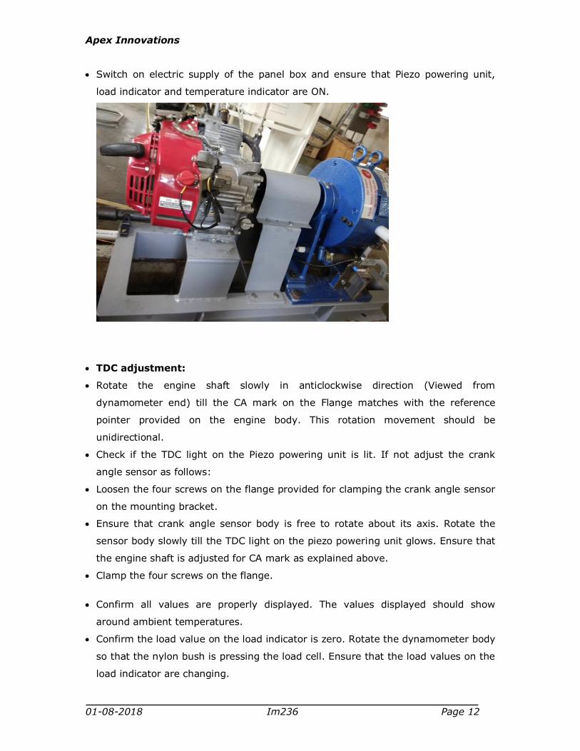
Switch on electric supply of the panel box and ensure that Piezo powering unit,
load indicator and temperature indicator are ON.
TDC adjustment:
Rotate the engine shaft slowly in anticlockwise direction (Viewed from
dynamometer end) till the CA mark on the Flange matches with the reference
pointer provided on the engine body. This rotation movement should be
unidirectional.
Check if the TDC light on the Piezo powering unit is lit. If not adjust the crank
angle sensor as follows:
Loosen the four screws on the flange provided for clamping the crank angle sensor
on the mounting bracket.
Ensure that crank angle sensor body is free to rotate about its axis. Rotate the
sensor body slowly till the TDC light on the piezo powering unit glows. Ensure that
the engine shaft is adjusted for CA mark as explained above.
Clamp the four screws on the flange.
Confirm all values are properly displayed. The values displayed should show
around ambient temperatures.
Confirm the load value on the load indicator is zero. Rotate the dynamometer body
so that the nylon bush is pressing the load cell. Ensure that the load values on the
load indicator are changing.
Apex Innovations
01-08-2018 Im236 Page 13
Engine starting:
Ensure that all foundation bolts, propeller shaft bolts are properly tightened.
Start the engine and allow it to run for 5 minutes in idling condition. Confirm that
engine speed is displayed on Piezo powering unit.
Rotate the knob on dynamometer loading unit and gradually load the engine.
Ensure that the load on the load indicator gradually increases.
Load the engine up to 2-3 kg allow it to run for 5 minutes.
Ensure that value displayed for one temperature sensor is logically correct.
Stop the engine after releasing the load.
For software installation on the computer proceed to Software section
Programming of load indicator (SV8 series)
If the load indicator shows error in load indication or if the program is disturbed
inadvertently it may need reprogramming/recalibration. Follow following steps.
Refer Load indicator documents in components’ manual and understand the
programming steps and key operations.
Calibration: If recalibration is needed fit the load cell on flat platform from bottom
side. On top surface of the load cell fix a flat sheet for placing which will hold the
weights up to 50 kg. (Capacity of load cell)
Precautions
Use clean and filtered water; any suspended particle may clog the piping.
Circulate dynamometer cooling water for some time after shutting down the
engine.
Piezo Sensor Handling:
Diaphragm of the sensor is delicate part. Avoid scratches or hammering.
A long sleeve is provided inside the hole drilled for piezo sensor. This sleeve is
protecting the surface of the diaphragm. While removing the sensor, this sleeve
may come out with the sensor and fall down or loose during handling.
Status of the sensor is indicated on the Piezo powering unit. Damages to the
electronic parts of the sensor or loose connection are indicated as "open" or
"Short" status on Piezo powering unit.

Apex Innovations
01-08-2018 Im236 Page 14
COMPUTER REQUIREMENT
Typical configuration as follows:
Computer with OS Windows 8 or higher, RAM Min 4 GB, DVD drive, high speed USB
port, Monitor with pixel setting 1200x900,
Refer ICEngineSoft DVD supplied with the setup. Follow the instructions and
instal the software
For instructions related to software refer help provided in the software.
Software

Apex Innovations
01-08-2018 Im236 Page 15
Note: For component specific problems refer components’ manual
Problems Possible causes / remedies
Engine does not start Ensure engine On-Off switch is at ON position
Apply choke
Insufficient fuel
Faulty spark plug
Release dynamometer load, if preloaded
Dynamometer does
not load the engine
Faulty wiring
No DC voltage at the outlet of dynamometer loading
unit
Faulty air flow Air hose leakage at connections with air-box and
with engine.
Faulty fuel flow Improper closing of fuel cock
Air trap in pressure signal line to fuel transmitter
Software does not
work
Faulty or wrong USB port
Virus in computer
Loose connections
Faulty indicated
power
TDC setting disturbed. Readjust TDC setting.
Improper configuration data
Faulty pressure crank
angle diagram
Improper earthing
Wrong reference pressure setting in configuration
file. Adjust the value such that suction stroke
pressure just matches the zero line.
If peak pressure is not at the TDC, TDC setting
disturbed, readjust
If peak pressure shifts randomly with respect to
TDC, coupling of crank angle sensor may be loose
Faulty speed
indication
Broken coupling of crank angle sensor
Incorrect
temperature
indication
Check the connection between thermocouple and
temperature indicator/transmitter. Note that yellow
cable of thermocouple is positive and red is
negative.
Troubleshooting

Apex Innovations
01-08-2018 Im236 Page 16
Open or damaged temperature sensor
Improper load
indication
Excessively raised jack bolts of the dynamometer.

Apex Innovations
01-08-2018 Im236 Page 17
1 Study of engine performance (Computerized mode)
OBJECT
To study the performance of 1 cylinder, 4 stroke, Petrol engine connected to dynamometer in computerized mode.
PROCEDURE
Ensure that all the nut bolts of engine, dynamometer, propeller shaft, base frame
are properly tightened.
Ensure that sufficient lubrication oil is present in the engine sump tank. This can
be checked by marking on the level stick (Use 20W 40 Engine Oil make any
company market available)
Ensure sufficient fuel in fuel tank. Remove air in fuel line, if any.
Switch on electric supply and ensure that PPU (Piezo powering unit), DLU
(Dynamometer loading unit), Load indicator and Temperature indicator are
switched on.
Start Computer and open "ICEngineSoft" (Double click "ICEngineSoft" icon on the
desktop) Click File | Configure | Product.
Select “Honda GX200” in Select file.
Otherwise click “Load Default” select “Honda GX200”. Check configuration values
& system constants with the values displayed on engine setup panel. Click on
"Save & Apply" after the changes corrections, if any.
Ensure water is flowing through dynamometer and piezo cooling adaptor.
Keep the DLU knob at minimum position on the engine panel.
Change the Fuel cock position from "Measuring" to "Tank"
Ensure that Engine Switch on the engine is at ON position.
Keep the throttle lever on the engine at minimum position
Start the engine by pulling Recoil rope and allow it to run at idling condition for 4
-5 minutes. Gradually increase the throttle lever to maximum position.
Click on "Mode" (Mode on is indicated by respective green light glow) in
ICEngineSoft
Click on " Measurement " (Measurement on is indicated by respective green light
glow)
Experiments

Apex Innovations
01-08-2018 Im236 Page 18
Note: Switching ON Measurement button will Start measuring, computing the
data, and display of results in form of calculated values, graphs, tables. User will
not be allowed to start measurement unless a configuration is loaded. Switching
OFF measurement will stop measuring.
Ensure that Speed, Temperatures and Manometer reading are correctly displayed
on the computer. These readings should tally with those displayed on the engine
panel.
Increase the load on the engine by rotating knob on the DLU and confirm the
load reading on the indicator and computer are same.
Adjust DLU knob to set engine speed @2000 RPM. Wait for 3 mins . Ensure that
RPM is constant during this period.
Change the Fuel cock position from "Tank" to "Measuring". Click "Log on" on. The
fuel metering is ON for next 30 seconds. Click OK after recording fuel reading.
Enter the file name under which the observations are be stored. The first
observation is now saved. Change the Fuel cock position from "Measuring" to
"Tank".
Decrease the load on the engine by manipulating DLU knob and set engine speed
@2400 RPM. Wait for 3 mins. Ensure that RPM is constant during this period.
Change the Fuel cock position from "Tank" to "Measuring". Click "Log on" on. The
fuel metering is ON for next 30 seconds. Click OK after recording fuel reading.
The second reading data is now saved. Change the Fuel cock position from
"Measuring" to "Tank".
Gradually decrease the load to increase speed in steps of @400 RPM up to
@3200 RPM and repeat the data logging for each observation.
After finishing all the readings decrease the load on the engine. Keep throttle
lever to minimum position.
Click on “Measurement” to stop data acquisition on Computer. Click on “Mode” to
stop the device communication.
Click File| Data| Close for storing the file on computer.
Stop the engine by changing engine switch to off position. Allow the water to
circulate for about 5 minutes for piezo cooling adaptor and then close water
supply.
Click: File |Data |Open. Select the file under which the observations are stored
and click "OK". To view next readings click "Next Data". The results are displayed
on all the three screens
Apex Innovations
01-08-2018 Im236 Page 19
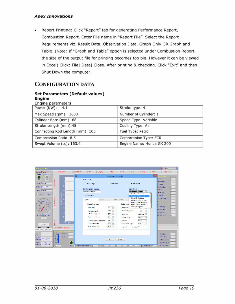
Report Printing: Click “Report” tab for generating Performance Report,
Combustion Report. Enter File name in “Report File”. Select the Report
Requirements viz. Result Data, Observation Data, Graph Only OR Graph and
Table. (Note: If “Graph and Table” option is selected under Combustion Report,
the size of the output file for printing becomes too big. However it can be viewed
in Excel) Click: File| Data| Close. After printing & checking. Click "Exit" and then
Shut Down the computer.
CONFIGURATION DATA
Set Parameters (Default values) Engine Engine parameters Power (KW): 4.1 Stroke type: 4
Max Speed (rpm): 3600 Number of Cylinder: 1
Cylinder Bore (mm): 68 Speed Type: Variable
Stroke Length (mm):45 Cooling Type: Air
Connecting Rod Length (mm): 105 Fuel Type: Petrol
Compression Ratio: 8.5 Compression Type: FCR
Swept Volume (cc): 163.4 Engine Name: Honda GX 200
Apex Innovations
01-08-2018 Im236 Page 20
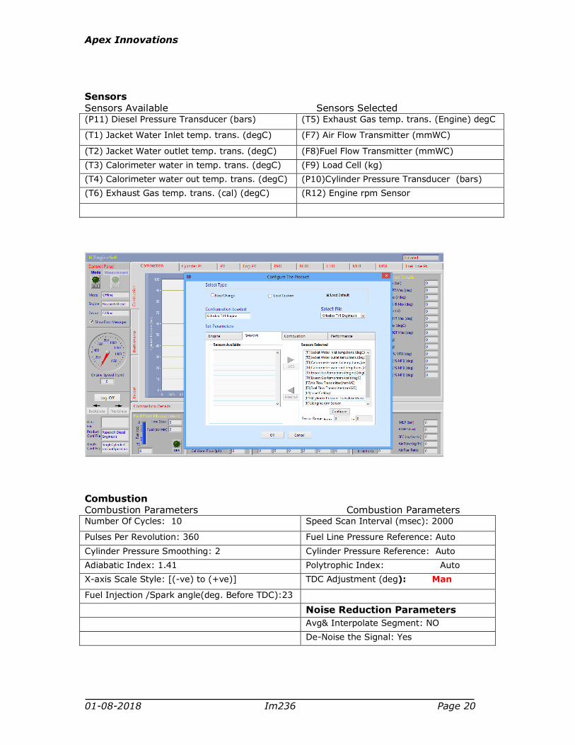
Sensors Sensors Available Sensors Selected (P11) Diesel Pressure Transducer (bars) (T5) Exhaust Gas temp. trans. (Engine) degC
(T1) Jacket Water Inlet temp. trans. (degC) (F7) Air Flow Transmitter (mmWC)
(T2) Jacket Water outlet temp. trans. (degC) (F8)Fuel Flow Transmitter (mmWC)
(T3) Calorimeter water in temp. trans. (degC) (F9) Load Cell (kg)
(T4) Calorimeter water out temp. trans. (degC) (P10)Cylinder Pressure Transducer (bars)
(T6) Exhaust Gas temp. trans. (cal) (degC) (R12) Engine rpm Sensor
Combustion Combustion Parameters Combustion Parameters Number Of Cycles: 10 Speed Scan Interval (msec): 2000
Pulses Per Revolution: 360 Fuel Line Pressure Reference: Auto
Cylinder Pressure Smoothing: 2 Cylinder Pressure Reference: Auto
Adiabatic Index: 1.41 Polytrophic Index: Auto
X-axis Scale Style: [(-ve) to (+ve)] TDC Adjustment (deg): Man
Fuel Injection /Spark angle(deg. Before TDC):23
Noise Reduction Parameters
Avg& Interpolate Segment: NO
De-Noise the Signal: Yes

Apex Innovations
01-08-2018 Im236 Page 21
Performance Fuel Parameters Constant Parameters Fuel Pipe Diameter(mm): 12.4 Water Density (kg/m^3): 1000
Fuel Measuring Interval(Sec): 30 Specific Heat of Water (kj/kg.K): 4.186
Calorific Value of Fuel (kj/kg): 44000
Fuel Density (kg/m^3): 740 Specific Heat of Gas (kj/kg.K): 1
Ambient Temperature (degC): 27
Setup Parameters Air Density (kg/m^3): 1.174
Orifice Diameter(mm): 16
Orifice Coefficient of Discharge: 0.6
Dynamometer Arm Length(mm): 185
Apex Innovations
01-08-2018 Im236 Page 22
2 STUDY OF ENGINE PERFORMANCE (MANUAL MODE)
OBJECT
To study the performance of 1 cylinder, 4 stroke, Petrol engine connected to dynamometer in manual mode
PROCEDURE
Ensure cooling water circulation for dynamometer, piezo sensor
Start the set up and run the engine at no load for 4-5 minutes.
Gradually increase throttle to full open condition and load the engine
simultaneously maintaining engine speed at @ 3200 RPM.
Wait for steady state (for @ 3 minutes) and collect the reading as per
Observations provided in “Cal236” worksheet in “Engine.xls”.
Gradually increase the load to decrease the speed in steps of @400 RPM up to
@ 2000 RPM and repeat the observations.
Fill up the observations in “Cal236” worksheet to get the results and
performance plots.

Apex Innovations
01-08-2018 Im236 Page 23
Components Details
Engine Make -Honda, Model -Honda GX200D QX, Type-Single
cylinder, 4 stroke Petrol, Air cooled, 4.1 KW at 3600
rpm, stroke 54 mm, bore 68 mm. Capacity 196 cc
Dynamometer Make Technomech Pvt. Ltd., Model TMEC10, Type Eddy
current
Dynamometer Loading
unit
Make Apex, Model AX-155. Type constant speed,
Supply 230V AC.
Propeller shaft Make Hindustan Hardy Spicer, Model 1260, Type A
Manometer Make Apex, Model MX-104, Range 100-0-100 mm,
Type U tube, Conn. 1/4`` BSP hose back side,
Mounting panel
Fuel measuring unit Make Apex, Glass, Model:FF0.012
Piezo sensor Make PCB Piezotronics, Model S111A22, Range 5000
psi, Diaphragm stainless steel type & hermetic sealed
White coaxial teflon cable Make PCB piezotronics, Model 002C20, Length 20 ft,
Connections one end BNC plug and other end 10-32
micro
Crank angle sensor Make Kubler, Model 8.KIS40.1361.0360 Clamping /
Synchro flange, 6x12.5mm shaft, IP64 Logic level:
RS422; Supply= 5VDC Square wave O/P: A, A’, B, B’,
0, 0’ Incr/turn: 360 PPR, Termination: 2m long axial
cable
Data acquisition device NI USB-6210 Bus Powered M Series Multifunction DAQ
Device, NI DAQmx driver Software
Piezo powering unit Make-Apex, Model AX-409.
Temperature sensor Make Radix Type K, Ungrounded, Sheath
Dia.6mmX110mmL, SS316, Connection 1/4"BSP (M)
adjustable compression fitting
Temperature transmitter Make ABUSTEK, Model : Fr Block, Input : Thermocouple (K), Range : 0 To 1200ºC, Output : 4-20 mA, Power supply : 24 V DC, Dimension : 44 X 25 MM, , Precalibrated to 1200 Deg C
Digital voltmeter Make Meco, 3.1/2 digit LED display, range 0-20 VDC,
Components used

Apex Innovations
01-08-2018 Im236 Page 24
supply 230VAC, model SMP35S
Load sensor Make SensotronicsSanmar Ltd., Model 60001,Type S
beam, Universal, Capacity 0-50 kg
Load indicator Load Indicator, Model Sleek 9010, Make Technomech
Size: 48X96
Power supply Make Meanwell, model NES-15-24, O/P 24 V, 0.7 A
Fuel flow transmitter Make Yokogawa, Model EJA110E-JMS5J-912NN,
Calibration range 0-500 mm H2O, Output linear
Air flow transmitter Make WIKA, Model SL-1-A-MQA-ND-ZA4Z-ZZZ, output
4-20 mA, supply 10-30 Vdc, conn. 1/2"NPT(M), Range
(-)25 - 0 mbar.
Apex Innovations
01-08-2018 Im236 Page 25
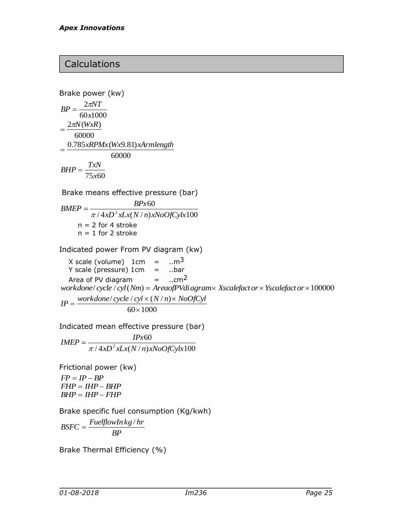
Brake power (kw)
100060
2
x
NTBP
60000
)(2 WxRN
60000
)81.9(785.0 xArmlengthWxxRPMx
6075x
TxNBHP
Brake means effective pressure (bar)
100)/(4/
602 xNoOfCylxnNxLxxD
BPxBMEP
n = 2 for 4 stroke n = 1 for 2 stroke
Indicated power From PV diagram (kw)
X scale (volume) 1cm = ..m3 Y scale (pressure) 1cm = ..bar
Area of PV diagram = ..cm2
100000)(// orYscalefactorXscalefactagramAreaofPVdiNmcylcycleworkdone
100060
)/(//
NoOfCylnNcylcycleworkdoneIP
Indicated mean effective pressure (bar)
100)/(4/
602 xNoOfCylxnNxLxxD
IPxIMEP
Frictional power (kw)
BPIPFP
BHPIHPFHP
FHPIHPBHP
Brake specific fuel consumption (Kg/kwh)
BP
hrkgFuelflowInBSFC
/
Brake Thermal Efficiency (%)
Calculations

Apex Innovations
01-08-2018 Im236 Page 26
CalValhrKgFuelFlowIn
BPBThEff
/
1003600
FuelHP
BHPOR
MechEffIThEffBThEff
100
Indicated Thermal Efficiency (%)
CalValhrKgFuelFlowIn
IPIThEff
/
1003600
MechEff
BThEffIThEff
100
Mechanical Efficiency (%)
IP
BPMechEff
100
Air flow (Kg/hr)
)/(24/ 2 AdenWdenghdCdAirFlow X3600 X Aden
Volumetric Efficiency
lAirFlowTheoretica
AirFlowVolEff
100
AdenNoOfCylnNStrokeD
AirFlow
60)/(4/
1002
Air fuel ratio
FuelFlow
AirFlowFA /
Heat Balance (KJ/h)
a) CalValFuelFlowedbyFuelHeatSuppli
b) 3600 BPulWorklentToUsefHeatEquiva
edByFuelHeatSuppli
ulWorklentToUsefHeatEquivaulWorkInlentToUsefHeatEquiva
100%
C) )12(3 TTWCFateretCoolingWHeatInJack P
Where F3 is rate of Jacket cooling water, T2 is jacket water outlet temperature and T1 is jacket water inlet temperature.
edByFuelHeatSuppli
ateretCoolingWHeatInJackaterInetCoolingWHeatInJack
100%
d) Heat in Exhaust (Calculate CPex value):
kKgKJTTFF
TTwCFexC P
P
0/..)65()21(
)34(4

Apex Innovations
01-08-2018 Im236 Page 27
Where, Cpex Specific heat of exhaust gas kJ/kg0K
Cpw Specific heat of water kJ/kg0K
F1 Fuel consumption kg/hr
F2 Air consumption kg/hr F4 Calorimeter water flow kg/hr T3 Calorimeter water inlet temperature 0K T4 Calorimeter water outlet temperature 0K T5 Exhaust gas to calorimeter inlet temp. 0K T6 Exhaust gas from calorimeter outlet temp. 0K
)5()21()/( TambTexCFFhKJustHeatInExha P
edByFuelHeatSuppli
ustHeatInExhaustHeatInExha
100%
e) Heat to radiation and unaccounted (%)
(%)}(%)
(%){(%)100(
ustHeatToExhaateretCoolingWHeatInJack
ulWorklentToUsefHeatEquivaedByFuelHeatSuppli

Apex Innovations
01-08-2018 Im236 Page 28
Wiring diagram

Apex Innovations
01-08-2018 Im236 Page 29
This product is warranted for a period of 12 months from the date of supply against
manufacturing defects. You shall inform us in writing any defect in the system
noticed during the warranty period. On receipt of your written notice, Apex at its
option either repairs or replaces the product if proved to be defective as stated
above. You shall not return any part of the system to us before receiving our
confirmation to this effect.
The foregoing warranty shall not apply to defects resulting from:
Buyer/ User shall not have subjected the system to unauthorized alterations/
additions/ modifications.
Unauthorized use of external software/ interfacing.
Unauthorized maintenance by third party not authorized by Apex.
Improper site utilities and/or maintenance.
We do not take any responsibility for accidental injuries caused while working with
the set up.
Apex Innovations Pvt. Ltd.
E9/1, MIDC, Kupwad, Sangli-416436 (Maharashtra) India
Telefax:0233-2644098, 2644398
Email: [email protected]: www.apexinnovations.co.in
Warranty


