
r e v . 0 3 r e l e a s e d 0 1 . 0 5 . 2 0 1 1 TECHNICAL M
ANUAL AND APPLICATION GUIDE
Medium-Voltage Switchgear MILE MP12, MP17 and MP24
Engineering Your Power
� Single Busbar Air-Insulated Metal-Clad Switchgear� Circuit Breaker mounted on withdrawable Cassette / Truck� All switching operations performed with front door closed
TECHNICAL MANUAL AND APPLICATION GUIDE
2WWW.TAVRIDA.EU
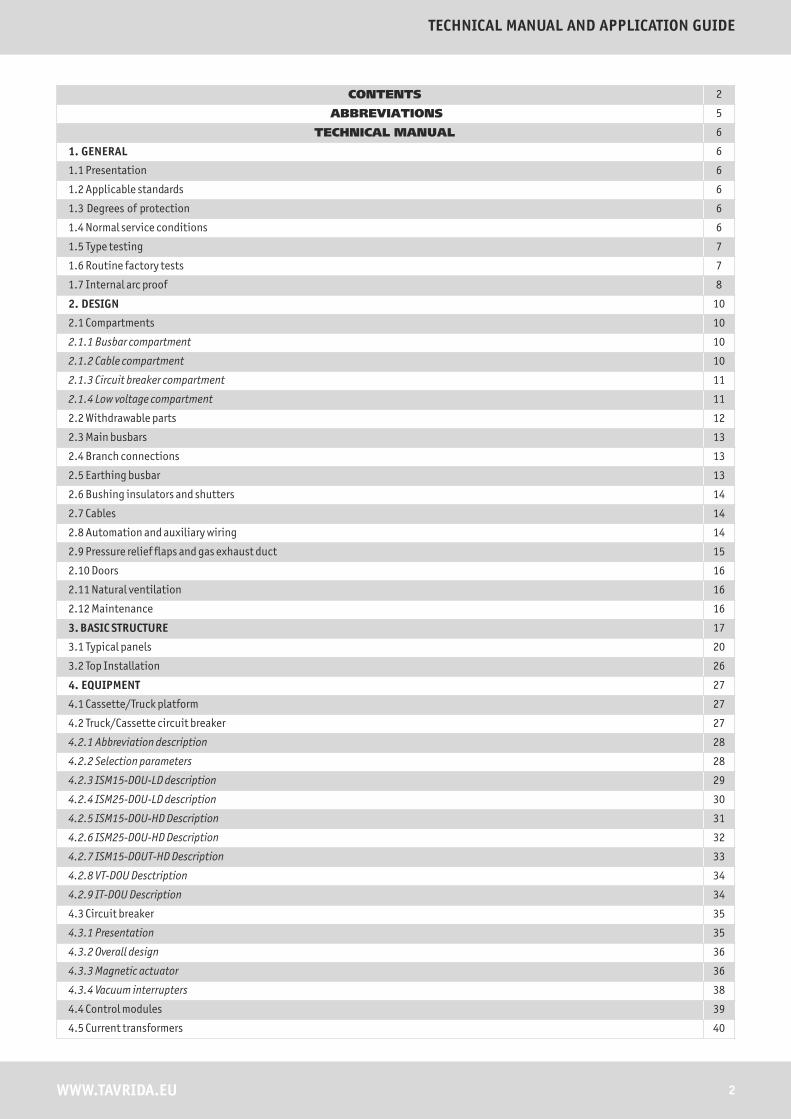
CONTENTS 2
ABBREVIATIONS 5
TECHNICAL MANUAL 6
1. GENERAL 6
1.1 Presentation 6
1.2 Applicable standards 6
1.3 Degrees of protection 6
1.4 Normal service conditions 6
1.5 Type testing 7
1.6 Routine factory tests 7
1.7 Internal arc proof 8
2. DESIGN 10
2.1 Compartments 10
2.1.1 Busbar compartment 10
2.1.2 Cable compartment 10
2.1.3 Circuit breaker compartment 11
2.1.4 Low voltage compartment 11
2.2 Withdrawable parts 12
2.3 Main busbars 13
2.4 Branch connections 13
2.5 Earthing busbar 13
2.6 Bushing insulators and shutters 14
2.7 Cables 14
2.8 Automation and auxiliary wiring 14
2.9 Pressure relief flaps and gas exhaust duct 15
2.10 Doors 16
2.11 Natural ventilation 16
2.12 Maintenance 16
3. BASIC STRUCTURE 17
3.1 Typical panels 20
3.2 Top Installation 26
4. EQUIPMENT 27
4.1 Cassette/Truck platform 27
4.2 Truck/Cassette circuit breaker 27
4.2.1 Abbreviation description 28
4.2.2 Selection parameters 28
4.2.3 ISM15-DOU-LD description 29
4.2.4 ISM25-DOU-LD description 30
4.2.5 ISM15-DOU-HD Description 31
4.2.6 ISM25-DOU-HD Description 32
4.2.7 ISM15-DOUT-HD Description 33
4.2.8 VT-DOU Desctription 34
4.2.9 IT-DOU Description 34
4.3 Circuit breaker 35
4.3.1 Presentation 35
4.3.2 Overall design 36
4.3.3 Magnetic actuator 36
4.3.4 Vacuum interrupters 38
4.4 Control modules 39
4.5 Current transformers 40

3
Medium-Voltage Switchgear MILE MP12, MP17 and MP24
WWW.TAVRIDA.EU
4.6 Voltage transformers 40
4.7 Zero sequence current transformer 40
4.8 Earthing switch 41
4.9 Surge Arresters 41
4.10 Cassette type to truck type transformation 42
5. INTERLOCKS AND LOCKING DEVICES 44
6. TECHNICAL SPECIFICATIONS 45
7. OVERALL DIMENSIONS 47
APPLICATION GUIDE 48
8. SELECTION 48
8.1 Selection description 48
9. INSTALLATION 49
9.1 Packaging, handling, storage 49
9.1.1 Packaging 49
9.1.2 Storage 50
9.2 Unpacking and installation of the equipment 50
9.2.1 Foundation surface 50
9.2.2 Unpacking panels 50
9.3 Panels installation, fixing and positioning 51
9.4 Positioning panels in switchboard 53
9.5 Connecting panels 53
9.5.1 Panels 53
9.5.2 Main busbar 54
9.5.3 Earthing busbar 54
9.5.4 Control cables interconnection 55
9.6 Fixing the cables 55
10. OPERATION 56
10.1 Withdrawable Parts Position Definitions 56
10.2 Interlocking Conditions 56
10.3 Interlock mechanisms 57
10.3.1 Standard supply 57
10.3.2 Optional supply 58
10.4 Locking facilities 60
10.5 Interlock between panels 60
10.6 Circuit breaker panel (IF, OF, BC) 61
10.6.1 Operations with draw-out unit 62
10.6.2 Operations with earthing switch 62
10.7 Metering panel (MES) 63
10.7.1 Operations of draw out unit with voltage transformer 64
10.7.2 Operations with busbar earthing switch 64
10.8 Load-break switch feeder (LBSF) 65
10.8.1 Operations with load break switch 65
10.8.2 Operations with earthing switch 65
10.9 Service trolley operation 66
10.9.1 Moving DOU from the removed position to the isolated position 68
10.9.2 Moving DOU from the isolated position to the removed position 69
10.10 Set of tools 70
10.11 Troubleshooting 70
10.12 CM Malfunction detection 71
10.13 Opening of the cable and circuit breaker compartment doors in emergency cases. Interlock overcoming. 71
LIST OF CHANGES 72
NOTES 73

4WWW.TAVRIDA.EU
TECHNICAL MANUAL AND APPLICATION GUIDE
It is absolutely necessary to read this document carefully before starting the installation or operation of MILE switchgear and to adhere to the instructions and the relevant regulations contained in it.
SAFETY FIRST
The user's personnel must act responsibly in all matters affecting safety at work and correct handling of the switchgear.
Make sure that during installation, commissioning and operation, the respective legal regulations (such as IEC) and appropriate national safety regulations are adhered to.
Make sure that the installation, commissioning and the operation are carried out by electrical specialists.
Only install the switchgear in closed rooms designated for electrical equipment.
Make sure that the specified data are not exceeded under the switchgear operation.
Make sure that this manual is available to all persons concerned with installation, commissioning and operation.
Note especially the important or danger information that is marked as follows in this manual:
Always follow the instruction manual and respect the rules of good engineering practice!Hazardous voltage can cause electrical shocks and burns. Disconnect power, then earth and short-circuit before proceeding with any work on this equipment.
WARNING!
Low voltage devices (mainly control modules) of all types meet the requirements of the EMC Directive 2006/95, the Low Voltage Directive 2004/108

5 WWW.TAVRIDA.EU
Medium-Voltage Switchgear MILE MP12, MP17 and MP24
Useful Features (useful and helpful information) are highlighted with:
Examples of calculations, hints:
Note especially the warnings that are marked with:
Technical stuff:
Danger! :
ABBREVIATION
TEL - Tavrida Electric (registered TM)TEE - Tavrida Electric Export Ltd.VCB - Vacuum circuit breakerMP - Medium-Voltage switchgear MILE typeDOU - Draw-out unitIEC - International Electrotechnical CommissionIP - International protectionISM - Indoor switching moduleCM - Control moduleLD - Low duty switching moduleHD - High duty switching moduleIAC - Internal arc classification RTU - Remote terminal unitIF - Incoming FeederOF - Outgoing FeederBC - Bus CouplerBR - Bus RiserBRES - Bus Riser with Earth SwitchBRM - Bus Riser with Metering TransformerM - Metering panelMES - Metering panel with Earth SwitchSTP - Service Transformer Panel LBSF - Load-Break Switch with Fuses

6WWW.TAVRIDA.EU
TECHNICAL MANUAL AND APPLICATION GUIDE
1.1 Presentation
The MILE MP series switchgear is designed for primary distribution networks with the rated voltages of 12kV, 17.5kV and 24kV 50/60Hz intended for indoor installation. The MILE MP series switchgear is air-insulated LSC2B-PM class, with single busbar design. The switchgear concept meets today's owner requirements such as reliability, personnel and operational safety, economy and efficiency in an optimal way. The switchgear is modular and is built up by placing standardized units side by side in a coordinated way. The switchgear is easy to configure and selection of the apparatus and instruments does not imply dedicated solutions.The functional units of the switchgear are guaranteed arc proof AFLR 31,5kA 1s in accordance with the IEC 62271-200 standard, appendix AA, class A accessibility, criteria 1 to 5. All the start-up, maintenance and service operations can be carried out from the front. The switchgear and the earthing switches are operated from the front with the door closed. The MILE MP series switchgear can be with front access or with front and rear access.
IEC 62271-1: High-voltage switchgear and controlgear – Part 1: Common specifications
IEC 62271-200: High-voltage switchgear and controlgear – Part 200: AC metal-enclosed switchgear and controlgear for rated voltages above 1 kV and up to and including 52 kV
IEC 62271-102: High-voltage switchgear and controlgear – Part 200: High-voltage alternating current disconnectors and earthing switches
IEC 60071-2: Insulation co-ordination – Part 2: Application guide
IEC 62271-100: High-voltage switchgear and controlgear – Part 100: High-voltage alternating current circuit-breakers
IEC 60265-1: High-voltage switches – Part 1: Switches for rated voltages above 1 kV and less than 52 kV
1.3 Degrees of protection
The degrees of protection of the switchgear conforms with IEC 60529 standard. The MILE MP series switchgear is normally supplied with the following standard degrees of protection:
� IP4X on the external housing
� IP3X with the doors open
1.4 Normal service conditions
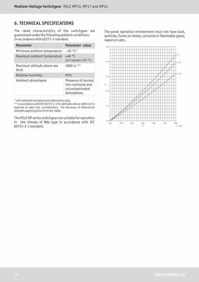
The rated characteristics of the switchgear are guaranteed under the following ambient conditions:In accordance with IEC 62271-1 standard.
Parameter Parameter value
Minimum ambient temperature - 40 °C*
Maximum ambient temperature +40 °C (on request +55 °C)
Maximum altitude above sea level
3000 m **
Relative humidity 95%
Ambient atmoshpere Presence of normal, non-corrosive and uncontaminated atmosphere.
TECHNICAL MANUAL
* with selected microprocessor electronics only.** in accordance with IEC 60721-2-1 for altitudes above 1000 m, it is required to take into consideration the decrease of dielectrical strength applying factor from the table.
The MILE MP series switchgear are suitable for operation in the climate of Wda type in accordance with IEC 60721-2-1 standard.
IP41 on request
This manual provides general information and specifications, intended for the selection of the switchgear.
1. GENERAL
1.2 Applicable standards
The switchgear and its main apparatus comply with the following standards:
Altitude above sea level, m
Air dielectric strength factor
1000 1,00
1200 0,98
1500 0,95
1800 0,92
2000 0,90
2500 0,85
3000 0,80

7 WWW.TAVRIDA.EU
Medium-Voltage Switchgear MILE MP12, MP17 and MP24
� Short-time and peak withstand current test on primary circuits
� Short-time and peak withstand current test on earthing circuits including draw out unit.
� Temperature rise and main circuit impedance measurements.
� Dielectric test on main and auxiliary circuits.
� Making and breaking capacity of the apparatus.
� Earthing switch making capacity.
� Mechanical operations.
� Verification of the IP coding
� Internal arc test.
1.6 Routine factory tests
Routine tests are performed by the assembly factory as specified in (the standard) IEC62271-200 to ensure the superior quality of each product to be delivered to a customer site:
Type tests:
1. Visual inspection
� Conformity of primary and secondary equipment
� Conformity of measuring instruments
� Enclosure
� Coating
� Equipment marking
� Wiring marking
� Wire conformity
� Conformity of neutral and protection wiring
2. Electrical wiring inspection
� Wire tightening check
� Wiring check as per project
3. Mechanical tests
� Enclosure fittings check
� Busbars and equipment tightening check
� Earthing tightening check
� Circuit breaker
� Draw-out unit
� Earthing switch
� Mechanical interlocks
4. Insulation resistance check
� Before
� L1-L2-L3
� (L1-L2-L3)-PE
� After
� L1-L2-L3
� (L1-L2-L3)-PE
5. Power frequency voltage test
� (L1-L2-L3)-E
� (L1)-E-L2-L3
� (L2)-E-L1-L3
� (L3)-E-L1-L2
6. Electrical operability tests
� Control circuits check
� Electrical interlock check
� Measuring circuits check
1.5 Type testing
The MILE switchgear has successfully passed all the tests specified by relevant IEC (International Standard) and GOST (Russian national standard) standards. As noted within the regulations of these standards, the tests were carried out on the switchgear units considered to be the most sensitive to stresses applied within the tests and therefore assigned to be valid on the whole range.

Cable fire(~600°C)
2 2I t, kA s
Total breaking timewith arc protection
16 ms
Copper fire(~1100°C)
8WWW.TAVRIDA.EU
TECHNICAL MANUAL AND APPLICATION GUIDE
1.7 Internal arc proof
The personnel safety factor was a primary goal when MILE switchgear was designed. Thus, the MILE switchgear has been designed and tested to withstand an internal arc due to a short-circuit current of the same levels as the panel rated breaking currents. These tests ensure that the metal construction of the MILE switchgear is able to protect personnel operating near the switchgear subjected to an internal arc fault. The internal arc is treated to be the most unlikely event from all type of faults, however a small percentage of occurrence still exists due to many factors including improper connection of incoming cables and tightening contact connections, intrusion of the animals, deterioration of the insulation within time or severe atmospheric conditions and human factor. The proved characteristics of the MILE switchgear drastically reduce the incidence of these causes in generation of faults, but some of them cannot be fully eliminated.
The event of internal arc produces a huge amount of energy which instantly transforms into phenomena such as rapid increase of the internal pressure and temperature, visual and sound effects, which consequently result in high mechanical stresses on the switchgear structure, structure and in melting and evaporation of the materials.
Such significant stresses, unless properly controlled, may cause serious life threat to the service personnel due to harmful effects (shock-wave, flying parts, doors opening, emission of hot gases, open flame).
The IEC 62271-200 Standard describes the test-methods and criteria to be used for testing. The MILE switchgear conforms to all criteria stated in the Annex A of the standard:
� The doors of the switchgear must remain closed and no opening of the cover panels must occur.
� No part of the switchgear, which may be hazardous for personnel, may be ejected.
� Arcing does not cause holes in the accessible sides up to a height of 2 m.
�
indicators placed outside the switchgear may not get burnt.
Vertically and horizontally arranged fabric
� All the switchgear earthing connections must remain effective.
The MILE switchgear is IAC classified: AFLR 31.5kA, 1s.For the installation of the MILE switchgear the following factors are obligatory to be considered:
� Level of the fault current (16...31.5 kA).
� Duration of the fault (0.1...1s).
� Hot gases evacuation routes.
�
special attention to the height.Dimensions of the switchboard room, with
TEE has developed various solutions providing effective control and protection over the arc initiation at earlier stages as well as passive type protection based on construction.
Steel fire(~1550°C)
0 100 200 400 ms

9 WWW.TAVRIDA.EU
Medium-Voltage Switchgear MILE MP12, MP17 and MP24
The arc protection system can be based on different types of arc detection sensors:- microswitches on pressure relief flap;- pressure sensors;- optical sensors with combination of earth-fault
detection;- phototyristor sensors.
Tavrida circuit breakers are designed with the entire concept in mind – optimizing vacuum interrupter, insulation, magnetic actuator and control modules. This has resulted in the fastest circuit breaker, the one cycle interrupter - a breakthrough for fast switching and arc flash protection technology.
Once the circuit breaker receives the trip signal from an arc-flash relay, it is able to interrupt in less than sixteen milliseconds (ms) to provide increased arc flash hazard mitigation – the fastest arc fault interruption in the industry – helping to reduce work-related injuries, fatalities and lost productivity.
10WWW.TAVRIDA.EU
TECHNICAL MANUAL AND APPLICATION GUIDE
2. DESIGN
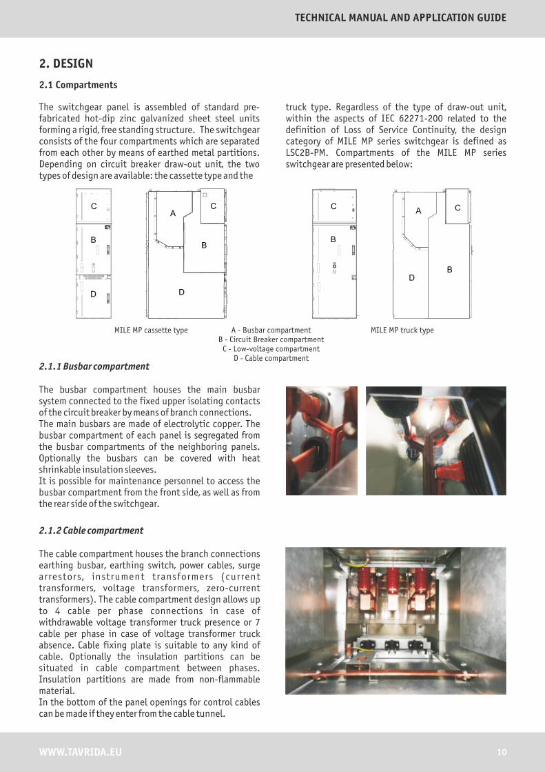
The switchgear panel is assembled of standard pre-fabricated hot-dip zinc galvanized sheet steel units forming a rigid, free standing structure. The switchgear consists of the four compartments which are separated from each other by means of earthed metal partitions. Depending on circuit breaker draw-out unit, the two types of design are available: the cassette type and the
A - Busbar compartmentB - Circuit Breaker compartment
C - Low-voltage compartmentD - Cable compartment
MILE MP cassette type MILE MP truck type
2.1.1 Busbar compartment
The busbar compartment houses the main busbar system connected to the fixed upper isolating contacts of the circuit breaker by means of branch connections.The main busbars are made of electrolytic copper. The busbar compartment of each panel is segregated from the busbar compartments of the neighboring panels. Optionally the busbars can be covered with heat shrinkable insulation sleeves. It is possible for maintenance personnel to access the busbar compartment from the front side, as well as from the rear side of the switchgear.
2.1.2 Cable compartment
The cable compartment houses the branch connections earthing busbar, earthing switch, power cables, surge arrestors , instrument transformers (current transformers, voltage transformers, zero-current transformers). The cable compartment design allows up to 4 cable per phase connections in case of withdrawable voltage transformer truck presence or 7 cable per phase in case of voltage transformer truck absence. Cable fixing plate is suitable to any kind of cable. Optionally the insulation partitions can be situated in cable compartment between phases. Insulation partitions are made from non-flammable material. In the bottom of the panel openings for control cables can be made if they enter from the cable tunnel.
2.1 Compartments
truck type. Regardless of the type of draw-out unit, within the aspects of IEC 62271-200 related to the definition of Loss of Service Continuity, the design category of MILE MP series switchgear is defined as LSC2B-PM. Compartments of the MILE MP series switchgear are presented below:
11 WWW.TAVRIDA.EU
Medium-Voltage Switchgear MILE MP12, MP17 and MP24
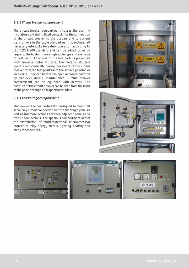
2.1.3 Circuit breaker compartment
The circuit breaker compartment houses the bushing insulators containing fixed contacts for the connection of the circuit breaker to the busbars and to current transformers in the cable compartment. It includes all necessary interlocks for safety operation according to IEC 62271-200 standard and can be added other on request. The bushings are single-pole type and are made of cast resin. An access to the live parts is prevented with movable metal shutters. The metallic shutters operate automatically during movement of the circuit breaker from the test position to the service position or vice versa. They can be fixed in open or closed position by padlocks during maintenance. Circuit breaker compartment can be equipped with heaters. The position of the circuit breaker can be seen from the front of the panel through an inspection window.
2.1.4 Low voltage compartment
The low-voltage compartment is designed to mount all secondary circuit connections within the single panel as well as interconnections between adjacent panels and transit connections. The spacious compartment allows the installation of multi-functional microprocessor protection relay, energy meters, lighting, heating and many other devices.

12WWW.TAVRIDA.EU
TECHNICAL MANUAL AND APPLICATION GUIDE
2.2 Withdrawable parts
There are the following types of draw out units available:
� Vacuum Circuit Breaker
� Isolating truck
� Voltage Transformer truck
� Earthing Truck
Draw out unit with CIRCUIT BREAKER (cassette/truck).The main purpose of a draw-out unit unit with circuit breaker is to make a visible break between the busbar and the cable compartment. It is needed for maintenance purposes in the cable compartment to guarantee personal safety. Also, it is used for comfortable service and testing of circuit breaker during commission of substation. The Draw out unit is equipped with all necessary interlocks for safety operation with panel in any condition.
Draw out unit with ISOLATING TRUCK.Isolation truck is located in Bus Riser panel and used formaking a visible break between sections of switchboardduring maintenance procedures.
Draw out unit with VOLTAGE TRANSFORMER TRUCK.A draw-out unit with voltage transformers is used for power metering of one feeder or the whole section and for providing voltage for protection devices. It can be placed in the circuit breaker or in the cable compartment. All voltage transformers can be equipped with striker type fuses to protect transformers against fault current.
Draw out unit with EARTHING TRUCK.An earthing truck is used for additional earthing of the switchgear. It do not have making capacity and providesonly safety earthing during maintenance procedures. This truck is designed for busbar or cable earthing.
Draw out unit with POWER CABLE TEST TRUCK.The truck is used for isolation tests of power cables without opening opening the cable compartment door and without disconnection of the cables from the switchgear.
Withdrawable parts can easily be easily taken out or moved into panels with a specially designed adjustable ramp (service trolley). To establish the isolating (TEST) position inside the panel, the withdrawable part is moved on bearings by means of a worm-gear mechanism. The withdrawable parts are connected to the earth bar through a sliding contact arranged to make and maintain contact when it is in the Service, Intermediate and Test positions.
Draw out unit with CB, cassette type
Draw out unit with CB, truck type
Isolating truck
Draw out unit with VT for circuit breaker compartment
Draw out unit with VT for cable compartment

13 WWW.TAVRIDA.EU
Medium-Voltage Switchgear MILE MP12, MP17 and MP24
2.3 Main busbars
The busbar compartment contains the main busbar system connected to the fixed upper contacts of the circuit breaker compartment by means of branch connections. The main busbars are made of electrolytic copper. The maximum rating of busbar system with natural cooling is 3150A. With compulsory cooling the busbar's nominal rating can exceed 4000A. The busbars are normally covered with heat shrinkable sleeves for the voltage ratings exceeding 6kV. Each busbar compartment within the panel is segregated from the other by means of partitions and supported by pass through insulators. The through insulators have been tested for their capability to withstand stresses due to electro-dynamic forces at the rated breaking currents.
2.4 Branch connections
The cable compartment contains the branch system for connection of the power cables to the fixed lower contacts of the circuit breaker compartment. The branch connections are made of electrolytic copper. The busbars are normally covered with heat shrinkable sleeves for the voltage ratings exceeding 12kV.
Crossections of the main and of the branch busbars can be different depending on the values of rated currents.
Main busbars
Main busbars rated current , А
Busbar, mm x mm
1250 1x10x80
2000 2х10х80
2500 3x10x80
3150 3x10x100
Branch busbars
Branch busbars rated current, А
Busbar, mm x mm
630 1х10х40
1000 1х10х60
1250 1х10х80
1600 2х10х80
2000 2х10х80
2500 3x10x80
3150 3x10x100
2.5 Earthing busbar
The earthing busbar is made of electrolytic copper with cross section 10x30mm. It runs along all adjacent panels and connects to a main earthing bar of substation. All current carrier parts are interconnected with each other to equipotential bonding to guarantee personal safety against electric shock.

14WWW.TAVRIDA.EU
TECHNICAL MANUAL AND APPLICATION GUIDE
2.6 Bushing insulators and shutters
The bushing insulators are located in the circuit breaker compartment, to hold fixed contacts and to be used for connection of the withdrawable unit to the busbar compartment and the cable compartment respectively. The bushing insulators are single-pole type and are made of cast resin. The shutters are made of metal and activated automatically during movement of the withdrawable unit from the test position to the service position or vice versa.
2.7 Cables
Single and three-core cables up to a maximum of seven per phase and up to 4 cables with voltage transformers can be used depending on the rated voltages, panel dimensions and the cable cross section. The switchgear can be put the wall.
� Auxiliary supply voltage: 24 .. 240 V AC/DC
� Any type of a microprocessor protection relay can be adopted
� Solenoid and electromagnet interlocks for earthing switch, draw out units, sectional earthing switch
� Heating for every compartment, lighting
� SCADA readiness
� Arc protection variety selection
� Commercial metering
� Electrical drives for draw-out unit and earthing switch
2.8 Automation and auxiliary wiring
Electrical wiring diagrams are the part of switchgear documentation delivered to a customer. A complete set of wiring diagrams for a typical substation is available with ABB, Micom, VAMP, SEL protection relays or other manufacturers.
On request, the wiring diagrams and consequently devices and instruments installed in switchgear can be customized to meet customer's specifications. A customer can benefit from the following options.

15 WWW.TAVRIDA.EU
Medium-Voltage Switchgear MILE MP12, MP17 and MP24
2.9 Pressure relief flaps and gas exhaust duct
Pressure relief flaps allow hot gases to be extracted from the compartment in the event of internal arc. A pressure relief flap is mounted at the top of each power
Pressure relief flaps design samples
Up to 630А nominal current. Flat single sheet
Over 630А nominal current. Multi edge construction
The gas exhaust duct is presumed to evacuate hot gases into dedicated areas. The evacuation of hot gases and other harmful particles can be effected to:
� Neighbouring rooms
� Outside restricted areas
� Dedicated panel with extinguishing cameras equipped with special filters
�
height) Upstream (special attention to the ceiling
The gas exhaust duct is fitted at the top of each panel and runs along the whole length of the switchboard. The pressure generated by the internal arc makes pressure relief flaps open thus allowing hot gases to run into the special chimney to be evacuated to the dedicated areas. A complete solution for every installation is to be specified separately.
compartment of a panel. TEE has designed different versions of the flaps depending on required IP level, nominal currents and rated breaking currents.

16WWW.TAVRIDA.EU
TECHNICAL MANUAL AND APPLICATION GUIDE
2.10 Doors
The powder coated doors are made from galvanized steel sheets, it provides a rigid structure and resistance to mechanical stresses. Robust hinges and handles provide for convenient and safe closing. Inspection windows are made from explosion-proof glass providing maximal safety for personal.
2.11 Natural ventilation circuit
Тhere is a natural ventilation circuit arranged around the circuit breaker to provide powerful extraction of the heat appearing due to circuit breaker operating at high currents or at high ambient temperatures. The cool air is sucked into the circuit, blown through the circuit breaker door and withdrawn from the panel through the gas exhaust channel. In case of internal arc blast, the reverse air current boosted by a high pressure instantly closes the special valve inside the shaft, thus preventing hot gases escaping from the panel.
2.12 Maintenance
Basically the MILE MP series switchgear is made with front access, but on request it can be made with front and rear access. For the rear access type the additional interlock is installed for the door blocking if the earthing switch is open.For the convenient access to the current transformers, the rotating CT plate solution has been designed for cable compartment.

17 WWW.TAVRIDA.EU
Medium-Voltage Switchgear MILE MP12, MP17 and MP24
An indoor switchboard consists of different number and types of MP panels with switching devices, control and protection relays, signaling and metering devices and
Truck type
1. Vacuum circuit breaker 8. Gas exhaust channel of the circuit breaker compartment
2. Primary contacts insulators 9. Gas exhaust channel of the busbar breaker compartment
3. Current transformers 10. Gas exhaust channel of the cable breaker compartment
4. Draw out unit with voltage transformers/fixed voltage transformers
11. Pressure relief flaps
5. Surge arresters 12. Support insulators with voltage indicator
6. Sealed cable entries 13. Shutter mechanism
7. Earthing switch 14. Main door with inspection window
15. Through insulators
3. Basic structure
other auxiliary equipment, which are interconnected by control cabling. The basic structures of the MP panels are given below.
Cassette type

18WWW.TAVRIDA.EU
TECHNICAL MANUAL AND APPLICATION GUIDE
Cross - section: cassette type
1. Vacuum circuit breaker 15. Bushing insulators
2. Voltage transformer aux connector 1 16. Earthing switch (make type)
3. Support insulator with a voltage indicator 17. Current transformers
4. Vacuum circuit breaker 18. Surge arresters
5. Circuit breaker aux connector 19. Outgoing cables
6. Live shutters 20. Bottom with sealed cable entries
7. Busbar earthing switch operation switch 21. Main earthing bar
8. Earthing switch control box 22. Earthing switch operation slot
9. Circuit breaker pressure relief flap 23. Ventilation provision
10. Operation mechanism for earthing switch 24. Cassette operation slot
11. Busbar compartment pressure relief flap 25. Circuit breaker emergency trip
12. Earthing switch top installation 26. Permission for operation with draw-out unit
13. Cable compartment pressure relief flap 27. Inspection window
14. Through insulator

19 WWW.TAVRIDA.EU
Medium-Voltage Switchgear MILE MP12, MP17 and MP24
Cross - section: truck type
1. Truck for circuit breaker 15. Earthing switch (make type)
2. Support insulator with a voltage indicator 16. Current transformers
3. Vacuum circuit breaker 17. Surge arresters
4. Circuit breaker aux connector 18. Outgoing cables
5. Live shutters 19. Bottom with sealed cable entries
6. Busbar earthing switch operation switch 20. Main earthing bar
7. Earthing switch control box 21. Earthing switch operation slot
8. Circuit breaker pressure relief flap 22. Truck operation slot
9. Operation mechanism for earthing switch 23. Circuit breaker emergency trip
10. Busbar compartment pressure relief flap 24. Permission for operation with draw-out unit
11. Earthing switch top installation 25. Inspection window
12. Cable compartment pressure relief flap
13. Through insulator
14. Bushing insulators

3.1 Typical panels
The available typical panels are presented below. The additional equipment or accessories for each panel can be coordinated within a certain order
IF - Incoming feeder
The Earthing Switch can be additionally interlocked with an electromagnet or electric drive from BC, BR, IF or upstream CB.
Cassette version
Truck version
* - optional.** - for truck type fixed voltage transformers only available.
TECHNICAL MANUAL AND APPLICATION GUIDE
20WWW.TAVRIDA.EU

Medium-Voltage Switchgear MILE MP12, MP17 and MP24
21 WWW.TAVRIDA.EU
OF- Outgoing feeder
Cassette version
Truck version
* - optional.** - for truck type fixed voltage transformers only available.

BC – Bus Coupler
BR – Bus Riser
TECHNICAL MANUAL AND APPLICATION GUIDE
22WWW.TAVRIDA.EU
* - optional.

BRM - Bus-riser with metering transformer
BRES - Bus-riser with earth switch
Medium-Voltage Switchgear MILE MP12, MP17 and MP24
23 WWW.TAVRIDA.EU
* - optional.

М - Metering panel
MES - Metering panel with earth switch
TECHNICAL MANUAL AND APPLICATION GUIDE
24WWW.TAVRIDA.EU
* - optional.

LBSF - Load-break switch with fuses panel
STP - Service transformer panel
Medium-Voltage Switchgear MILE MP12, MP17 and MP24
25 WWW.TAVRIDA.EU
* - optional.

3.2 Top Installation
Depending on requirements and structure of panel types in single line diagram the busbar earthing switch or voltage transformer can be installed over the top of any panel.Earthing switch in top installation can be equipped with support insulator with capacitor sensors and electromagnet for providing necessary interlocks.
TECHNICAL MANUAL AND APPLICATION GUIDE
26WWW.TAVRIDA.EU
Earthing switch top installation
Voltage transformer top installation
1 Branch busbar
2 Support insulators
3 Earthing switch
4 Earthing switch mechanism
5 Socket for earthing switch operating tool
6 Openings for control cables
7 Voltage transformers
2
1
3
5
4
6
6
7
2
1

4. EQUIPMENT
Medium-Voltage Switchgear MILE MP12, MP17 and MP24
27 WWW.TAVRIDA.EU
4.1 Cassette/Truck platform
The following equipment can be istalled onto draw-out units depending on their functionality: circuit breaker, Voltage transformers, isolating truck. The equipment is fixed onto a metal support and handling cassette/truck platform. The cassette/truck platform is provided with a wheel system which makes the operations for racking the apparatus in and out of the switchgear possible with the door closed.
The truck/cassette platform allows efficient earthing of the apparatus by means of the sliding earth busbar contact and the metal structure of the switchgear. The apparatus cassette/truck platform can be motor operated. The rack-in and rack-out operations can be carried out by means of electrical controls, either locally by an operator or by a remote system.
+ =
Cassette Frame Truck type platform
4.2 Truck/Cassette circuit breaker
Tavrida Electric has designed draw-out units ISM-DOU series for application in distribution networks with rated voltages 12-24kV 50/60Hz. These draw out units are based on ISM switching modules and intended for indoor applications in air-insulated switchgear of withdrawable design and MILE MP compatible cradles and power-boxes.
ISM-DOU is completely type tested within metal-clad switchgear as per latest standards:
� IEC 62271-100: High-voltage switchgear and controlgear – Part 100: High-voltage alternating current circuit-breakers
� IEC 62271-200: High-voltage switchgear and controlgear – Part 200: AC metal-enclosed switchgear and controlgear for rated voltages above 1 kV and up to and including 52 kV
� GOST 14694: Metal-clad switchgear up to 10 kV. Test methods.

TECHNICAL MANUAL AND APPLICATION GUIDE
28WWW.TAVRIDA.EU
ISMXX-DOU-XX-XX/XXX-XXX-xX4.2.1 Abbreviation description
Draw-out unit typeRated voltage, kVDraw-out unitPlace of voltage transformersShort circuit current, kARated current, A Pole center distance, mmDraw-out unit interlock type
Draw-out unit type ISM – Circuit breaker; IT – Isolation truck; VT – Voltage transformer truck
Rated voltage, kV 15 (12-17.5) or 25 (24kV)
Draw-out unit DOU – Cassette; DOUT - Truck
Place of voltage transformers CC – VT in cable compartment; CB – VT in circuit breaker compartment.
Short circuit current, kA 16; 20; 25; 31,5;
Rated current, A 630; 800; 1000; 1250;2000;2500;3150
Pole center distance, mm 150; 210; 250
Draw-out unit interlock type e1 – version with electromagnet 110Ve2 - version with electromagnet 220Vm1 – version with motor drive 110Vm2 – version with motor drive 220V
4.2.2 Selection parameters
Example:ISM15-DOU-25/2000-210-e1
Draw-out unit type ISM – Circuit breaker
Rated voltage, kV 15 (12-17.5)
Draw-out unit DOU – Cassette
Short circuit current, kA 25;
Rated current, A 2000
Pole center distance, mm 210
Draw-out unit interlock type e1 - version with electromagnet 110V
*- LD circuit breaker type rated current is 630A is only.
VCB-DOU Selection table:
Rated voltage/PCD distance
Rated currents
630A 1250A 2000A 2500A
12/17.5kV150 PCD
ISM15D-LD/1-150 ISM15D-HD/1-150
12/17.5kV210 PCD
ISM15D-HD/1-210 ISM15D-HD/2-210
12/17.5kV275 PCD
ISM15D-HD/3-275
24kV210 PCD
ISM25D-LD/1-210 ISM25D-HD/1-210
24kV275 PCD
ISM25D-HD/2-275
Medium-Voltage Switchgear MILE MP12, MP17 and MP24
29 WWW.TAVRIDA.EU
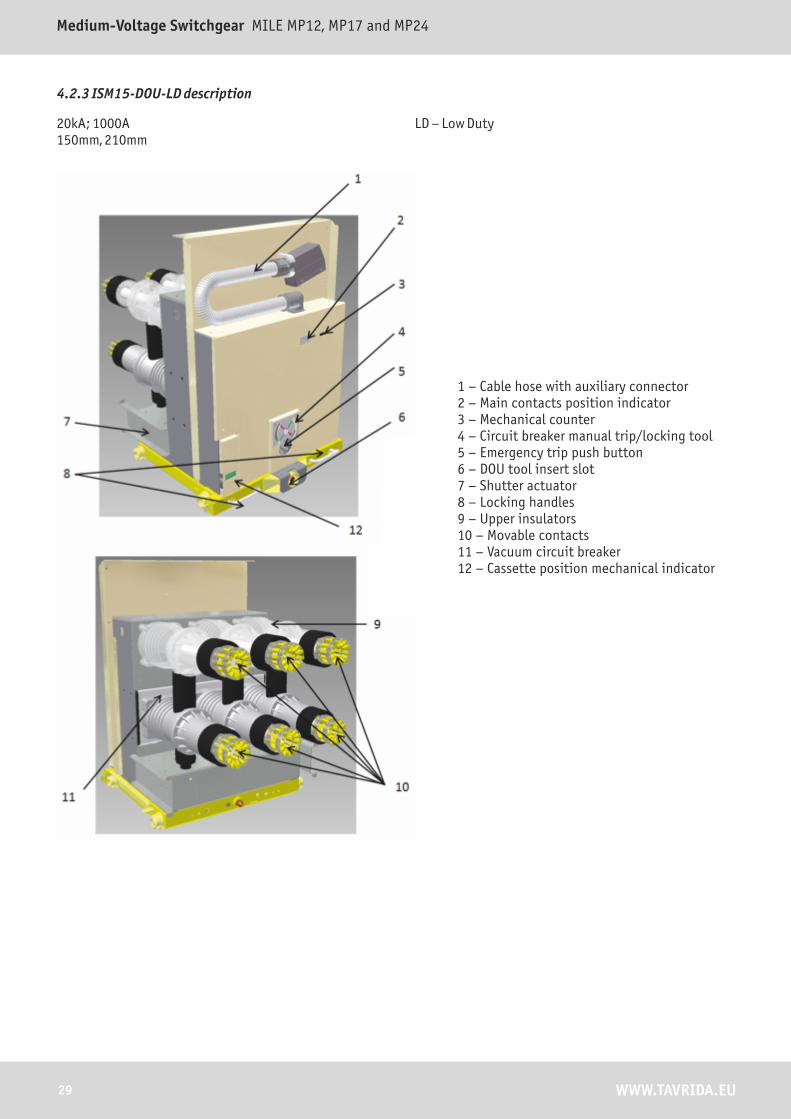
4.2.3 ISM15-DOU-LD description
20kA; 1000A150mm, 210mm
LD – Low Duty
1 – Cable hose with auxiliary connector2 – Main contacts position indicator3 – Mechanical counter4 – Circuit breaker manual trip/locking tool5 – Emergency trip push button6 – DOU tool insert slot7 – Shutter actuator8 – Locking handles9 – Upper insulators10 – Movable contacts11 – Vacuum circuit breaker12 – Cassette position mechanical indicator

TECHNICAL MANUAL AND APPLICATION GUIDE
30WWW.TAVRIDA.EU
4.2.4 ISM25-DOU-LD description
16kA; 800A210mm, 275mm
LD – Low Duty
1 – Cable hose with auxiliary connector2 – Main contacts position indicator3 – Mechanical counter4 – Circuit breaker manual trip/locking tool5 – Emergency trip push button6 – DOU tool insert slot7 – Shutter actuator8 – Locking handles9 – Upper insulators10 – Movable contacts11 – Vacuum circuit breaker12 – Cassette position mechanical indicator

31 WWW.TAVRIDA.EU
Medium-Voltage Switchgear MILE MP12, MP17 and MP24
4.2.5 ISM15-DOU-HD Description
25kA, 31.5kA630A, 1250A, 1600A, 2000A, 2500(3150)A150mm, 210mm, 275mm
HD – High Duty
1 – Cable hose with auxiliary connector2 – Main contacts position indicator3 – Mechanical counter4 – Circuit breaker manual trip/locking tool5 – Emergency trip push button6 – DOU tool insert slot7 – Shutter actuator8 – Locking handles9 – Upper insulators10 – Movable contacts11 – Vacuum circuit breaker12 – Cassette position mechanical indicator
6
8
4
5
2
3
7
9
10
1
12
11

32WWW.TAVRIDA.EU
TECHNICAL MANUAL AND APPLICATION GUIDE
4.2.6 ISM25-DOU-HD Description
25kA630A, 1250A210mm, 275mm
HD – High Duty
1 – Cable hose with auxiliary connector2 – Main contacts position indicator3 – Mechanical counter4 – Circuit breaker manual trip/locking tool5 – Emergency trip push button6 – DOU tool insert slot7 – Shutter actuator8 – Locking handles9 – Upper insulators10 – Movable contacts11 – Vacuum circuit breaker12 – Cassette position mechanical indicator
33 WWW.TAVRIDA.EU
Medium-Voltage Switchgear MILE MP12, MP17 and MP24
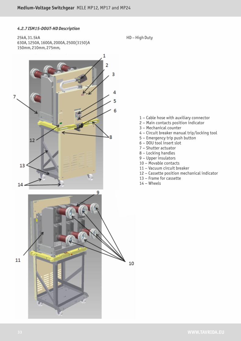
4.2.7 ISM15-DOUT-HD Description
25kA, 31.5kA630A, 1250A, 1600A, 2000A, 2500(3150)A150mm, 210mm, 275mm,
HD – High Duty
1 – Cable hose with auxiliary connector2 – Main contacts position indicator3 – Mechanical counter4 – Circuit breaker manual trip/locking tool5 – Emergency trip push button6 – DOU tool insert slot7 – Shutter actuator8 – Locking handles9 – Upper insulators10 – Movable contacts11 – Vacuum circuit breaker12 – Cassette position mechanical indicator13 – Frame for cassette14 – Wheels

4.2.8 VT-DOU Desctription
4.2.9 IT-DOU Description
1 – Voltage transformers2 - Cable hose with auxiliary connector3 – Cassette4 – Secondary circuits terminals5 – Movable contacts6 – Support Insulators7 - Shutter actuator
34WWW.TAVRIDA.EU
TECHNICAL MANUAL AND APPLICATION GUIDE
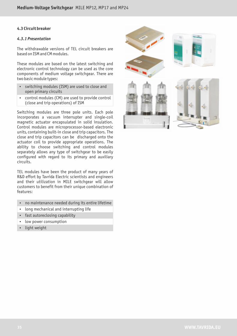
4.3 Circuit breaker
4.3.1 Presentation
The withdrawable versions of TEL circuit breakers are based on ISM and CM modules.
These modules are based on the latest switching and electronic control technology can be used as the core components of medium voltage switchgear. There are two basic module types:
� switching modules (ISM) are used to close and open primary circuits
� control modules (CM) are used to provide control (close and trip operations) of ISM
Switching modules are three pole units. Each pole incorporates a vacuum interrupter and single-coil magnetic actuator encapsulated in solid insulation. Control modules are microprocessor-based electronic units, containing built-in close and trip capacitors. The close and trip capacitors can be discharged onto the actuator coil to provide appropriate operations. The ability to choose switching and control modules separately allows any type of switchgear to be easily configured with regard to its primary and auxiliary circuits.
TEL modules have been the product of many years of R&D effort by Tavrida Electric scientists and engineers and their utilization in MILE switchgear will allow customers to benefit from their unique combination of features:
� no maintenance needed during its entire lifetime
� long mechanical and interrupting life
� fast autoreclosing capability
� low power consumption
� light weight
35 WWW.TAVRIDA.EU
Medium-Voltage Switchgear MILE MP12, MP17 and MP24

4.3.2 Overall design
In contrast to the majority of conventional circuit breakers, this patented design incorporates three independent magnetic actuators: one per pole. This minimizes the number of moving parts and makes all of these parts coaxial. The vacuum interrupter and the magnetic actuator are located at opposite ends of a hollow support insulator. The actuator armature is rigidly coupled to the vacuum interrupter moving contact by a linear drive insulator within the support insulator. This provides direct linear movement in both directions and avoids the use of rotating shafts, bearings and bell cranks. The result is a maintenance free ISM with a long trouble-free mechanical life. The actuators are situated inside the frame as shown in the figure below. A synchronizing shaft connects the three poles and performs three functions:
� opening synchronization of the poles
� operation of auxiliary switches
� link drive for mechanical interlocks on switchgear
4.3.3 Magnetic actuator
The actuator is held in its two end positions without the use of mechanical latches:
� in the OPEN position the armature is held by the opening spring
� in the CLOSED position the armature is held by the magnetic flux produced by a ring magnet
This actuator has only one coil. To close and trip the actuator it is necessary to inject current into the coil in different directions.
LD (low-duty) ISM circuit breaker pole cross-section
34WWW.TAVRIDA.EU
TECHNICAL MANUAL AND APPLICATION GUIDE

HD (high-duty) ISM circuit breaker pole cross-section
Stator of actuator
Support insulator
Upper terminal
Vacuum interrupter
Crown-type flexible contact
Lower terminal
Pulling insulator
Actuator coil
Armature of actuator
Opening and additional contact pressure springs
Main contacts position indicator actuator
Interlocking shaft
Auxiliary terminals
Sinchronizing shaft
37 WWW.TAVRIDA.EU
Medium-Voltage Switchgear MILE MP12, MP17 and MP24

As soon as the vacuum interrupter contacts open, the interrupting current initiates a so-called "vacuum arc" that burns essentially as plasma originating from evaporated contact material. The current continues to flow through this plasma until a zero current is reached. At this moment the arc is extinguished and a transient recovery voltage appears across the open gap. If the contact surface is locally overheated, it produces a lot of vapour, resulting in the deterioration of the vacuum followed by an electrical breakdown. To avoid this, effective control of the vacuum arc is necessary. The most effective way to achieve this goal is to apply an
� high interrupting capacity
� very compact dimensions
� low chopping current (4-5 amps) This limits inductive switching overvoltages to safe values
� axial magnetic field minimizes contact erosion and ensures a very long and reliable life
4.3.4 Vacuum interrupters
axial magnetic field produced by the interrupting current itself. This method is implemented in vacuum interrupters developed and manufactured by Tavrida Electric for ISM modules. Several major benefits result from this design:
The family of TEL vacuum interrupters Finely dispersed vacuum arc resulting from stabilizing effect of axial magnetic field
38WWW.TAVRIDA.EU
TECHNICAL MANUAL AND APPLICATION GUIDE

4.4 Control modules
Description Code Remarks Picture
Control Module СM_12_1(220) 110,220VDC100-230VAC
Control Module СM_12_1(60) 24, 48, 64VDC
Control Module СM_12_2(220) 110,220VDC100-230VAC
Control Module СM_12_2(60) 24, 48, 64VDC
Control Module СM_12_3(220) 110,220VDC100-230VAC
Control Module СM_12_3(60) 24, 48, 64VDC
Control Module СM_15_1(230) 110,220VDC100-230VAC
Control Module СM_15_1(60) 24, 48, 64VDC
Manual generator SS30-WA 110VDC
39 WWW.TAVRIDA.EU
Medium-Voltage Switchgear MILE MP12, MP17 and MP24
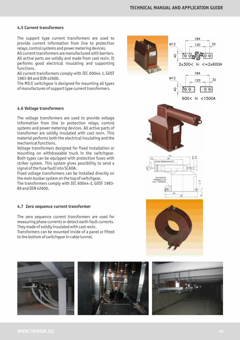
The support type current transformers are used to provide current information from line to protection relays, control systems and power metering devices. All current transformers are manufactured with barriers. All active parts are solidly and made from cast resin. It performs good electrical insulating and supporting functions.All current transformers comply with IEC 60044-1, GOST 1983-89 and DIN 42600.The MILE switchgear is designed for mounting all types of manufactures of support type current transformers.
The voltage transformers are used to provide voltage information from line to protection relays, control systems and power metering devices. All active parts of transformer are solidly insulated with cast resin. This material performs both the electrical insulating and the mechanical functions. Voltage transformers designed for fixed installation or mounting on withdrawable truck in the switchgear. Both types can be equipped with protection fuses with striker system. This system gives possibility to send a signal of the fuse fault into SCADA. Fixed voltage transformers can be installed directly on the main busbar system on the top of switchgear. The transformers comply with IEC 60044-2, GOST 1983-89 and DIN 42600.
4.5 Current transformers
4.6 Voltage transformers
4.7 Zero sequence current transformer
The zero sequence current transformers are used for measuring phase currents or detect earth fault currents. They made of solidly insulated with cast resin. Transformers can be mounted inside of a panel or fitted to the bottom of switchgear in cable tunnel.
40WWW.TAVRIDA.EU
TECHNICAL MANUAL AND APPLICATION GUIDE
WWW.TAVRIDA.EU
Medium-Voltage Switchgear MILE MP12, MP17 and MP24
41
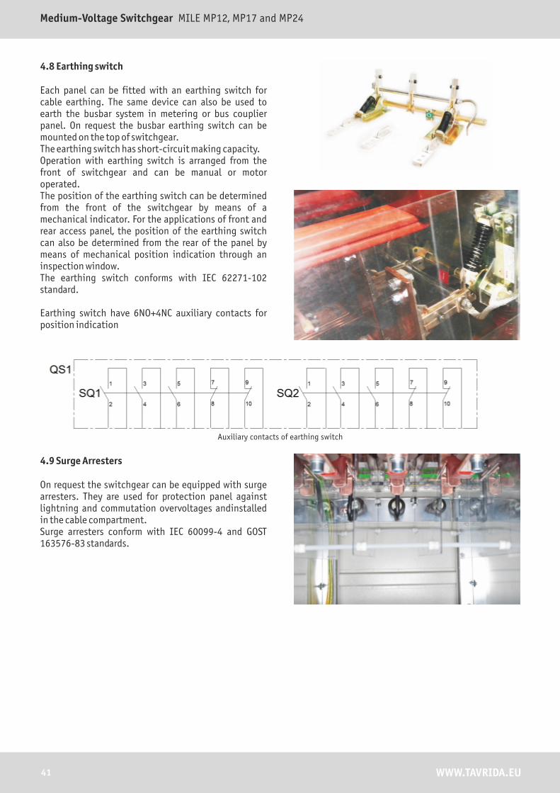
4.8 Earthing switch
Each panel can be fitted with an earthing switch for cable earthing. The same device can also be used to earth the busbar system in metering or bus couplier panel. On request the busbar earthing switch can be mounted on the top of switchgear. The earthing switch has short-circuit making capacity. Operation with earthing switch is arranged from the front of switchgear and can be manual or motor operated. The position of the earthing switch can be determined from the front of the switchgear by means of a mechanical indicator. For the applications of front and rear access panel, the position of the earthing switch can also be determined from the rear of the panel by means of mechanical position indication through an inspection window.The earthing switch conforms with IEC 62271-102 standard.
Earthing switch have 6NO+4NC auxiliary contacts for position indication
4.9 Surge Arresters
On request the switchgear can be equipped with surge arresters. They are used for protection panel against lightning and commutation overvoltages andinstalled in the cable compartment.Surge arresters conform with IEC 60099-4 and GOST 163576-83 standards.
Auxiliary contacts of earthing switch

4.10 Cassette type to truck type transformation
The basic design of the MILE MP/TEE panel is identical for both cassette and truck types. There are only four parts that differ between cassette and truck type panels.
front doors, intermediate plate, cable compartment covers special floor slides.
The cassette type panel can be easily transformed into the truck type panel.
�
�
�
�
The truck type VCB has the same cassette draw-out unit installed onto a special floor-rolling cassette extension. The cassette VCB can be easily transformed into truck type VCB by fixing it with the 4 bolts onto cassette extension.The pictures of the cassette and truck type VCBs are shown below.
Cassette Truck type
To transform the cassette type panel into truck one the 4 steps should be taken.
Remove cable and circuit breaker compartment doors.
42WWW.TAVRIDA.EU
TECHNICAL MANUAL AND APPLICATION GUIDE
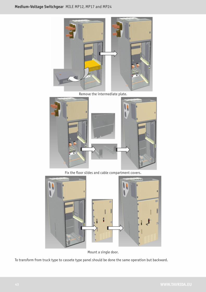
Remove the intermediate plate.
43 WWW.TAVRIDA.EU
Medium-Voltage Switchgear MILE MP12, MP17 and MP24
Fix the floor slides and cable compartment covers.
Mount a single door.
To transform from truck type to cassete type panel should be done the same operation but backward.

5. INTERLOCKS AND LOCKING DEVICES
The switchgear is fitted with all interlocks needed to guarantee the highest level of safety for operators.According to IEC 62271-200 the interlocking devices prevent:
� closing of a circuit breaker in the intermediate position
� racking-out of a circuit breaker in the closed position
� racking-in of a circuit breaker in the closed position
� opening of the circuit breaker compartment door as long as the circuit breaker is not in the test position
� racking-in of the circuit breaker while the compartment door is open
In addition, if a panel is equipped with an earthing switch, the interlocking devices prevent:
� racking-in of the circuit breaker while the earthing switch is closed
� closing of the earthing switch when the circuit breaker is in the connected or intermediate positions
� opening of the cable compartment door while the earthing switch is open
� opening of the earthing switch while the circuit breaker compartment door is open
Cable and circuit breaker department doors can be locked by means of padlocks.The operations of circuit breaker racking-in/out and earthing switch opening/closing can be prevented by applying the padlocks or castle lock to the corresponding openings or slots.The metal shutters can be locked by means of two independent padlocks in both the open and the closed positions.
44WWW.TAVRIDA.EU
TECHNICAL MANUAL AND APPLICATION GUIDE
6. TECHNICAL SPECIFICATIONS
The rated characteristics of the switchgear are guaranteed under the following ambient conditions:In accordance with 62271-1 standard.
The panel operation environment must not have dust, particles, fumes or smoke, corrosive or flammable gases, vapors or salts.
Parameter Parameter value
Minimum ambient temperature - 40 °C*
Maximum ambient temperature +40 °C (on request +55 °C)
Maximum altitude above sea level
3000 m **
Relative humidity 95%
Ambient atmoshpere Presence of normal, non-corrosive and uncontaminated atmosphere.
* with selected microprocessor electronics only.** in accordance with IEC 60721-2-1 for altitudes above 1000 m, it is required to take into consideration the decrease of dielectrical strength applying factor from the table.
The MILE MP series switchgear are suitable for operation in the climate of Wda type in accordance with IEC 60721-2-1 standard.
45 WWW.TAVRIDA.EU
Medium-Voltage Switchgear MILE MP12, MP17 and MP24
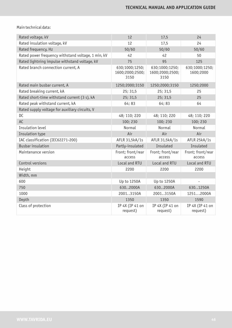
Rated voltage, kV 12 17,5 24
Rated insulation voltage, kV 12 17,5 24
Rated frequency, Hz 50/60 50/60 50/60
Rated power frequency withstand voltage, 1 min, kV 42 42 50
Rated lightning impulse withstand voltage, kV 75 95 125
Rated branch connection current, А 630;1000;1250;1600;2000;2500;
3150
630;1000;1250;1600;2000;2500;
3150
630;1000;1250;1600;2000
Rated main busbar current, А 1250;2000;3150 1250;2000;3150 1250;2000
Rated breaking current, kA 25; 31,5 25; 31,5 25
Rated short-time withstand current (3 s), kA 25; 31,5 25; 31,5 25
Rated peak withstand current, kA 64; 83 64; 83 64
Rated supply voltage for auxiliary circuits, V
DC 48; 110; 220 48; 110; 220 48; 110; 220
AC 100; 230 100; 230 100; 230
Insulation level Normal Normal Normal
Insulation type Air Air Air
IAC classification (IEC62271-200) AFLR 31,5kА/1s AFLR 31,5kА/1s AFLR 25kА/1s
Busbar insulation Partly-insulated Insulated Insulated
Maintenance version Front; front/rear access
Front; front/rear access
Front; front/rear access
Control versions Local and RTU Local and RTU Local and RTU
Height 2200 2200 2200
Width, mm
600 Up to 1250A Up to 1250A -
750 630..2000A 630..2000A 630..1250A
1000 2001..3150A 2001..3150A 1251...2000A
Depth 1350 1350 1590
Class of protection IP 4X (IP 41 on request)
IP 4X (IP 41 on request)
IP 4X (IP 41 on request)
Main technical data:
46WWW.TAVRIDA.EU
TECHNICAL MANUAL AND APPLICATION GUIDE

7. OVERALL DIMENSIONS
Voltage Width, A mm Depth, B mm Height, C mm
12kV 600, 750, 1000 1350 2200
17,5kV 600, 750, 1000 1350 2200
24kV 750, 1000 1590 2200
12-17,5 kV
*STP and LBSF cubicle maximum ratings are 630A
24 kV
Depth (mm) 1350
Height (mm) 2200
Width (mm) 1000
750
600
Weight (kg) 780 930 1050
Rated current (A) 630 1250 1600 2000 2500 3150
IF
OF
BC
BR
BRES
M
MES
LBSF*
STP*
Depth (mm) 1560
Height (mm) 2200
Width (mm) 1000
750
Weight (kg) 1010 1100
Rated current (A) 630 1250 1600 2000 2500
IF
OF
BC
BR
BRES
M
MES
LBSF*
STP*
47 WWW.TAVRIDA.EU
Medium-Voltage Switchgear MILE MP12, MP17 and MP24

APPLICATION GUIDE
8. SELECTION
8.1 Selection description
Rated voltage, kV 12, 17.5, 24
Rated breaking current, kA 20; 25; 31.5
Rated current, A 630; 1250; 1600; 2000; 2500(3150)
Type of panel IF, OF, BC, BR, BRM, BRES, M, MES, LBSF, STP
Main busbars rated current, A A-1250, B-2000, C-2500(3150)
Width, mm 600, 750, 1000
Selection parameters:
Example:MILE MP-17.5-25/2000-OF-B-750
MILE MP-XX-XX/XXX-XXX-X-XXX
MILE type panel
Rated voltage, kV
Rated breaking current, kA
Branch busbars rated current, A
Type of panel
Main busbars rated current, A
Width, mm
This guide provides instructions for installation and use of the switchgear.
Rated voltage, kV 17.5
Rated breaking current, kA 25
Rated current, A 2000
Type of panel OF
Main busbars rated current, A 2000
Width, mm 750
48WWW.TAVRIDA.EU
TECHNICAL MANUAL AND APPLICATION GUIDE
9. INSTALLATION
9.1 Packaging, handling, storage
9.1.1 Packaging
Each panel is delivered vertically, in separate packaging. State of the equipment before packaging:
� withdrawable parts are removed.
� earthing switch closed.
The packaging of panel for road transport:
� enveloped in plastic stretch wrapping
(thickness > 100μ),
� belted with sticky tape.
The packaging of panel for air and sea transport:
� enveloped in plastic stretch wrapping
(thickness > 100μ),
� packed in wooden crates.
Withdrawable parts (circuit breakers, isolating trucks, voltage transformer trucks) are contained in wooden crates. Additional equipment and spare parts packed separately or together in one package.
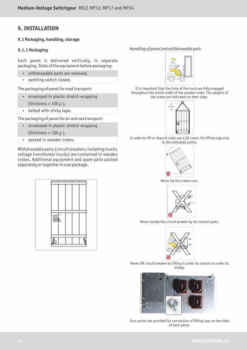
Handling of panel and withdrawable part:
It is important that the forks of the truck are fully engaged throughout the entire width of the wooden crate. The weights of
the crates are indicated on their sides.
In order to lift or deposit crate use a jib crane. Fix lifting lugs only to the indicated points.
Never tip the crates over.
Never handle the circuit breaker by its contact parts.
Never lift circuit breaker by lifting it under its chassis or under its trolley.
Four points are provided for connection of lifting lugs on the sides of each panel.
49 WWW.TAVRIDA.EU
Medium-Voltage Switchgear MILE MP12, MP17 and MP24

41
Lift the panel unit by 4 lifting lugs.
Slide the panel, using three cylindrical rollers of 30 mm
min. diameter.
Use special provisions on withdrawable units for lifting.
All lifting, towing equipment must be in good condition, checked, regularly inspected according to national safety rules. Always lift the equipment in a balanced mode.
9.1.2 Storage
Panels must be stored indoors. The storage area must be free of dust particles, fumes or smoke, corrosive or flammable gases, vapors or salts.
9.2 Unpacking and installation of the equipment
9.2.1 Foundation surface
The installation of a switchboard requires a flat, concrete structure. The following requirements to the floor surface must be obeyed:
� Evenness tolerance: ± 1mm within a measuring length of 1m
� Straightness tolerance: 1mm per 1m, but not more than 3mm over entire length of frame.
Floor, ceiling and walls of the building must be finished with materials, which do not raise or collect dust.
9.2.2 Unpacking panels
Unpacking panels should only take place on the installation site. Remove plastic stretchwrapping from the panel. Visually inspect the exterior of panel.
50WWW.TAVRIDA.EU
TECHNICAL MANUAL AND APPLICATION GUIDE

9.3 Panels installation, fixing and positioning
Panels must be positioned on the site in accordance with developed and approved civil project and electrical diagram. The openings on the floor forpassage high-voltage cables must be provided. The openings for the passage of the low-voltage cables must be reserved as shown on the picture.The openings for the passage of the low-voltagecables must be reserved as shown on the picture.
1 – Passage for high-voltage cables
2 – Opening 60x200 for passage of low-voltage cables (Optional)
3 – Fixing places with floor by anchor bolts
51 WWW.TAVRIDA.EU
Medium-Voltage Switchgear MILE MP12, MP17 and MP24
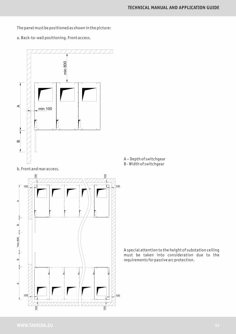
The panel must be positioned as shown in the picture:
a. Back-to-wall positioning. Front access.
b. Front and rear access.
A special attention to the height of substation ceiling must be taken into consideration due to the requirements for passive arc protection.
A – Depth of switchgearB - Width of switchgear
52WWW.TAVRIDA.EU
TECHNICAL MANUAL AND APPLICATION GUIDE
Depending on short-circuit current levels and application of gas exhaust chimney the following table must be considered for selection of ceiling height of the substation.
The exit area for hot gases evacuation must be chosen carefully with the consideration of the following points:
� The area must be restricted for access of personnel
� The area must be clearly indicated
� The hot gases must not harm the equipment or machinery located nearby
� The access of water, animals, and small objects into the exhaust chimney must be prevented
9.4 Positioning panels in a switchboards
Panels must be positioned in accordance with the single-line diagram. If switchboard is composed of 1-10 panels, it is recommended to begin installation from the first panel, counting from a side opposite to the room entry. If switchboard is composed of more than 10 panels, then begin the installation from the middle of the switchboard.
Rated short cicuit current
20kA 25kA 31.5kA
Arcing time 0.5 sec 1 sec 0.5 sec 1 sec 0.5 sec 1 sec
Ceiling height without gas exhaust chimney (H)
H>2,8 m H>3 m H>3 m H>3,5 m H>3,5 m H>4 m
Ceiling height with gasexhaust chimney (H)
H>2,8 m H>2,8 m H>2,8 m H>2,8 m H>2,8 m H>2,8 m
9.5 Connecting panels
9.5.1 Panels
Make sure that all panels are perpendicular in relation to the floor surface. Align up the front facing panels.Proceed with the layout of the other panels by repeating the same checks each time.
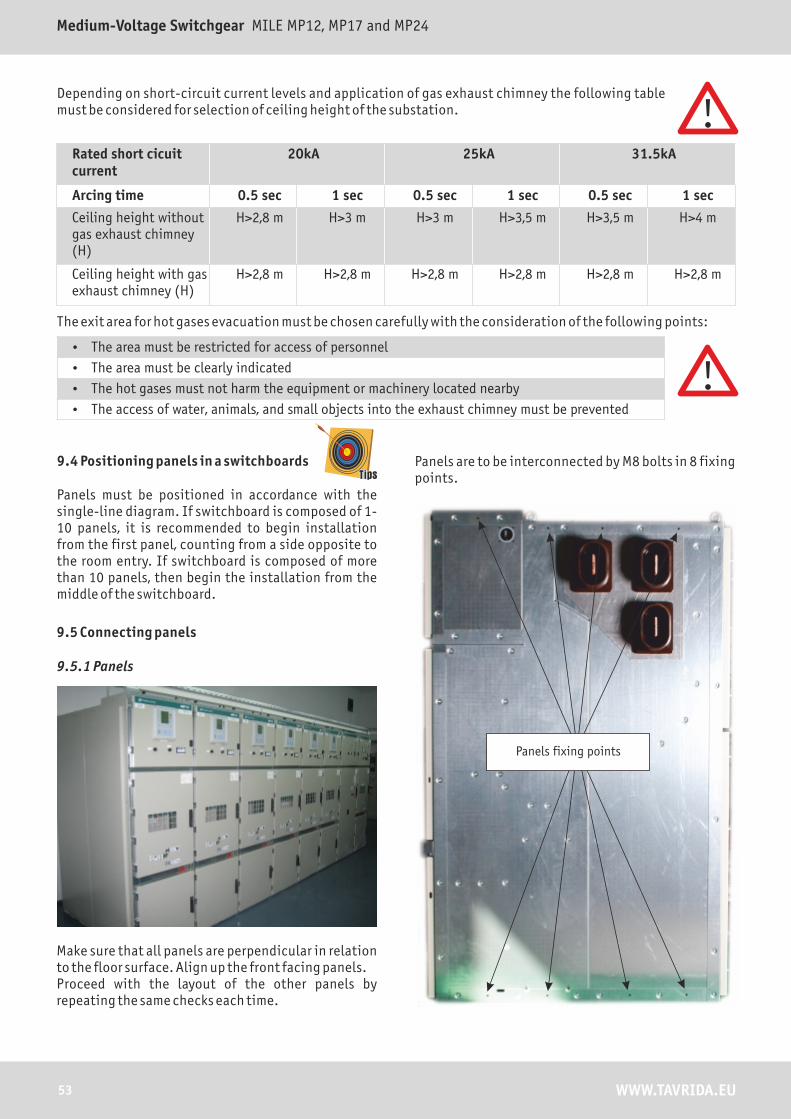
Panels are to be interconnected by M8 bolts in 8 fixing points.
Panels fixing points
53 WWW.TAVRIDA.EU
Medium-Voltage Switchgear MILE MP12, MP17 and MP24

9.5.2 Main busbar
Before the assembling of main busbar on substation, the connection surface must be cleaned by wire brush for better electrical contact. Position connection places and fix them together with the help of 4xМ12х65 bolts.
Main busbar
Branch busbarBolt connection
Recommended tightening torques for busbar bolt connection:
Bolt connection size
Tightening torque without lubricant, Nm
Tightening torque with
lubricant, Nm
M6 10,5 4,5
M8 26 10
M10 44,1 30
M12 74,6 40
M16 165 80
M20 250 160
9.5.3 Earthing busbar
The earthing bar is inserted into the cable compartment through the special rectangular openings and fixed by bolt M8x45. Make sure that contact surface of earthing busbar is flat and clean. Connection between earthing busbar of panels and main earthing bar of substation must be done according to maximum earth-fault current of switchgear.
Adjoin the earth busbar to the connection point and fix with M12 bolt.
54WWW.TAVRIDA.EU
TECHNICAL MANUAL AND APPLICATION GUIDE

9.5.4 Control cables interconnection
The interconnection between panels is realized by the control cables through openings in both sides of the low voltage compartment. For connection with external devices (DC distribution board or SCADA) the openings are provided from the top and from the bottom of the cable compartment.
Opening for transit cables
9.6 Fixing the cables
Before connection the cables make sure that cables are without voltage, the CB is in OPEN position and the earthing switch is in CLOSED position.
Cable fixations Cable glands
55 WWW.TAVRIDA.EU
Medium-Voltage Switchgear MILE MP12, MP17 and MP24

10. OPERATION
10.1 Withdrawable Parts Position Definitions
Service position
� Main circuits are connected
� Auxiliary circuits are connected
� The circuit breaker can be CLOSED and OPENED
� The circuit breaker compartment door is closed and cannot be opened
Intermediate position
� The withdrawable part is between the service and the test positions
� Auxiliary circuits are connected
� The circuit breaker is OPENED and interlocked
� The circuit breaker compartment door is closed and cannot be opened
Test position
� Main circuits are disconnected
� Auxiliary circuits are connected
� The circuit breaker can be CLOSED and OPENED for testing purposes
� The circuit breaker compartment door can be opened and closed
Isolated position
� Main circuits are disconnected
� Auxiliary circuits are disconnected
� The circuit breaker cannot operate
� The circuit breaker compartment door is open and cannot be closed
Removed position
� The withdrawable part is physically removed from the panel
10.2 Interlocking Conditions
� It shall not be possible to rack out the withdrawable part from the service position to the test position when the circuit breaker is CLOSED. Similarly, it shall not be possible to rack in the withdrawable part from the test position to the service position, if the circuit breaker is CLOSED.
� Any attempt to rack out the withdrawable part from the service position to the test position shall not result in TRIPPING of the Circuit Breaker.
� It shall not be possible to rack in or rack out the withdrawable part when the circuit breaker compartment door is open.
� It shall not be possible to rack in the withdrawable part from the isolated position to the service position when the low voltage control plug is not connected. Similarly, it shall not be possible to close the circuit breaker compartment door in the isolated position unless the low voltage control plug is connected.
� It shall only be possible to CLOSE the earthing switch if provided, when the withdrawable part is in the test position. This ensures physical isolation between the withdrawable part and the busbar and cables.
� It shall not be possible to rack in the withdrawable part from the test position to the service position, in case the cable earthing switch is CLOSED.
� It shall not possible to operate the circuit breaker when the breaker is in the intermediate position between the service position and the test and vice versa.
� Additionally, an electro-magnetic interlock shall be provided for earthing switches of incomer and coupler panels. Alternately earthing trucks can be supplied with the electro-magnetic interlock.
56WWW.TAVRIDA.EU
TECHNICAL MANUAL AND APPLICATION GUIDE

Conditions to be met
Operations CB CB in Feeder Earthing Switch with Mechanical
Interlock
Respective Busbar Earthing Switch
Circuit breaker compartment Door with Mechanical
Interlock
Open Closed Test Position
Service Position
Open Closed Open Closed Open Closed
Test Position -CB closing
X X
Test Position -CB opening
X X
Service Position -CB closing
X X X* X X*
Service Position -CB opening
X X X* X X*
CB Moving from
Service position to Test position
X X* X X*
Test position to Service Position
X X* X X*
Feeder Earthing Switch
Closing X X X X**
Opening X X X X**
Bus Earthing Switch
Closing X X X X
Opening X X X X
LV Plug
Disconnecting X X X
Connecting X X X
X - Conditions to be met* - Mechanical Interlock** - mechanical interlock related to the cable compartment door for the cassette version.
10.3 Interlock mechanisms
10.3.1 Standard supply
The basic set of interlocks provides electrical and mechanical interlocks of the following operations according to IEC 62271-200
� Operation of the circuit breaker (CLOSE/TRIP)
� Operation of the DOU (rack in/out)
� Operation of the earthing switch (CLOSE/OPEN)
The interlocks are provided by the design of the withdrawable part and earthing switch mechanisms.
WWW.TAVRIDA.EU
Medium-Voltage Switchgear MILE MP12, MP17 and MP24
57
10.3.2 Optional supply
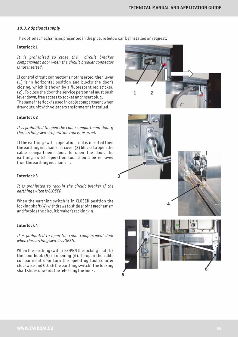
The optional mechanisms presented in the picture below can be installed on request:
Interlock 1
It is prohibited to close the circuit breaker compartment door when the circuit breaker connector is not inserted.
If control circuit connector is not inserted, then lever (1) is in horizontal position and blocks the door's closing, which is shown by a fluorescent red sticker. (2). To close the door the service personnel must push lever down, free access to socket and insert plug. The same interlock is used in cable compartment when draw out unit with voltage transformers is installed.
Interlock 2
It is prohibited to open the cable compartment door if the earthing switch operation tool is inserted.
If the earthing switch operation tool is inserted then the earthing mechanism's cover (3) blocks to open the cable compartment door. To open the door, the earthing switch operation tool should be removed from the earthing mechanism.
Interlock 3
It is prohibited to rack-in the circuit breaker if the earthing switch is CLOSED.
When the earthing switch is in CLOSED position the locking shaft (4) withdraws to slide a joint mechanism and forbids the circuit breaker's racking-in.
Interlock 4
It is prohibited to open the cable compartment door when the earthing switch is OPEN.
When the earthing switch is OPEN the locking shaft fix the door hook (5) in opening (6). To open the cable compartment door turn the operating tool counter clockwise and CLOSE the earthing switch. The locking shaft slides upwards the releasing the hook.
58WWW.TAVRIDA.EU
TECHNICAL MANUAL AND APPLICATION GUIDE

Interlock 5
It is prohibited to rack-in or rack-out the withdrawable part when the circuit breaker is CLOSED. To rack in or rack out withdrawable part it is needed to turn the permission key for operation with draw-out unit (6) counterclockwise to 90°. It opens access to the rack-in mechanism (7). If the circuit breaker was CLOSED during turning key (6), interlock trip the circuit breaker to prevent danger situation.
Interlock 6
The DOU movement from the test position to the service position is prohibited unless the circuit breaker compartment door is closed.
With the door closing the door hook (8) presses on the DOU engaging slide, which releases the DOU operating mechanism.
Interlock 7
It is prohibited to operate the earthing switch when cable compartment door is open.
When closing the door the blade fits into an opening, releasing a locking pin (9) which allows access to the earthing switch slot.When the door is opened the locking pin is engaged.
Interlock 8
The circuit breaker compartment door opening is prohibited unless DOU is not in the test position.
After DOU started racking in, the end of the bracket engaged by the shutters mechanism moves downward and blocks the door hook.
59 WWW.TAVRIDA.EU
Medium-Voltage Switchgear MILE MP12, MP17 and MP24

10.4 Locking facilities
A standard double bit key lock can be used for locking DOU in the test and service positions.
The earthing switch can be locked with
a padlock.
Live shutters can be securely locked in the open and closed positions with a padlock.
The access to the circuit breaker or cable compartments can be
restricted with the padlocks or key-locks
(optionally).
10.5 Interlock between panels (optional)
� The busbar earthing switch can only be closed when all the withdrawable parts of a relative busbar section are in the test position (electromechanical interlock )
� When the busbar earthing switch is closed, the withdrawable parts of the earthed busbar section cannot be moved from the test position to the service position (electromechanical interlock)
60WWW.TAVRIDA.EU
TECHNICAL MANUAL AND APPLICATION GUIDE

10.6 Circuit breaker panel (IF, OF, BC)
VCB READY EMERGENCY TRIP
PROTECTION RELAY
REMOTE/LOCAL SWITCHVOLTAGE INDICATOR
Table with switchgear technical parameters
Inspection window
Socket for draw out unit interlock
Emergency trip push button
Socket for operation with draw-out unit
Socket for operation with earthing switch
Ventilation canal
61 WWW.TAVRIDA.EU
Medium-Voltage Switchgear MILE MP12, MP17 and MP24
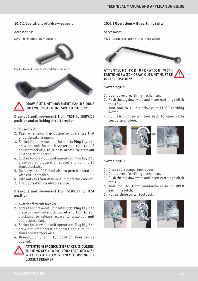
10.6.1 Operations with draw-out unit
Accessories:
Key 1 – for interlock draw-out unit
Key 2 – For rack-in and rack-out draw-out unit
DRAW-OUT UNIT MOVEMENT CAN BE DONE ONLY WHEN EARTHING SWITCH IS OPEN!
Draw-out unit movement from TEST to SERVICE position and switching circuit breaker
1. Close the door.2. Push emergency trip button to guarantee that
circuit breaker is open. 3. Socket for draw-out unit interlock: Plug key 1 to
draw-out unit interlock socket and turn to 90° counterclockwise to release access to draw-out unit operation socket.
4. Socket for draw out unit operation: Plug key 2 to draw-out unit operation socket and turn it 20 times clockwise.
5. Turn key 1 to 90° clockwise to permit operation with circuit breaker.
6. Take out key 1 from draw-out unit interlock socket7. Circuit breaker is ready for service.
Draw-out unit movement from SERVICE to TEST position
1. Switch off circuit breaker.2. Socket for draw-out unit interlock: Plug key 1 to
draw-out unit interlock socket and turn to 90° clockwise to release access to draw-out unit operation socket.
3. Socket for draw out unit operation: Plug key 2 to draw-out unit operation socket and turn it 20 times counterclockwise.
4. Draw-out unit is in TEST position. Door can be opened.
ATTENTION! IF CIRCUIT BREAKER IS CLOSED, TURNING KEY 1 TO 90° COUNTERCLOCKWISE WILL LEAD TO EMERGENCY TRIPPING OF CIRCUIT BREAKER.
10.6.2 Operations with earthing switch
Accessories:
Key 3 – Tool for operation with earthing switch
AT T E N T I O N ! F O R O P E R AT I O N W I T H EARTHING SWITCH DRAW-OUT UNIT MUST BE IN TEST POSITION!
Switching ON
1. Open cover of earthing mechanism. 2. Push the tag downward and insert earthing switch
tool (3).3. Turn tool to 180° clockwise to CLOSE earthing
switch.4. Pull earthing switch tool back to open cable
compartment door.
Switching OFF
1. Close cable compartment door.2. Open cover of earthing mechanism.3. Push the tag downward and insert earthing switch
tool (3).4. Turn tool to 180° counterclockwise to OPEN
earthing switch.5. Pull earthing switch tool back.
62WWW.TAVRIDA.EU
TECHNICAL MANUAL AND APPLICATION GUIDE

10.7 Metering panel (MES)
VOLTAGE INDICATOR
Table with switchgear technical parameters
Inspection window
Socket for draw out unit interlock
Socket for operation with draw-out unit
Socket for operation with earthing switch
Ventilation canal
63 WWW.TAVRIDA.EU
Medium-Voltage Switchgear MILE MP12, MP17 and MP24

10.7.1 Operations of draw out unit with voltage transformer
Accessories:
Key 1 – for interlock draw-out unit
Key 2 – For rack-in and rack-out draw-out unit
DRAW-OUT UNIT MOVEMENT CAN BE DONE ONLY WHEN EARTHING SWITCH IS OPEN!
Draw-out unit with VT movement from TEST to SERVICE position
1. Close the door.2. Socket for draw out unit interlock: Plug key 1 to
draw-out unit interlock socket and turn to 90° counterclockwise to release access to draw-out unit operation socket.
3. Socket for draw out unit operation: Plug key 2 to draw-out unit operation socket and turn it 20 times clockwise.
4. Turn key 1 to 90° clockwise to permit operation with circuit breaker.
5. Take out key 1 from draw-out unit interlock socket.
Draw-out unit with VT movement from SERVICE to TEST position
1. Socket for draw-out unit interlock: Plug key 1 to draw-out unit interlock socket and turn to 90° clockwise to release access to draw-out unit operation socket.
2. Socket for draw out unit operation: Plug key 2 to draw-out unit operation socket and turn it 20 times counterclockwise.
3. Draw-out unit is in TEST position. Door can be opened.
10.7.2 Operations with busbar earthing switch
Accessories:
Key 3 – Tool for operation with earthing switch
AT T E N T I O N ! F O R O P E R AT I O N W I T H EARTHING SWITCH DRAW-OUT UNIT MUST BE IN TEST POSITION!FOR OPERATION WITH BUSBUR EARTHING SWITH IN METERING PANEL, ALL DRAW OUT UNITS OF WHOLE SECTION MUST BE IN TEST POSITION.
Switching ON
1. Open cover of earthing mechanism. 2. Push the tag downward and insert earthing switch
tool (3).3. Turn tool to 180° clockwise to CLOSE earthing
switch.4. Pull earthing switch tool back to open cable
compartment door.
Switching OFF
1. Close cable compartment door.2. Open cover of earthing mechanism.3. Push the tag downward and insert earthing switch
tool (3).4. Turn tool to 180° counterclockwise to OPEN
earthing switch.5. Pull earthing switch tool back.
64WWW.TAVRIDA.EU
TECHNICAL MANUAL AND APPLICATION GUIDE
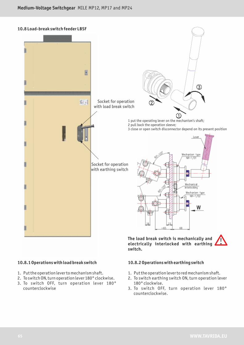
10.8 Load-break switch feeder LBSF
Socket for operation with load break switch
Socket for operation with earthing switch
10.8.1 Operations with load break switch
1. Put the operation lever to mechanism shaft.2. To switch ON, turn operation lever 180° clockwise.3. To switch OFF, turn operation lever 180°
counterclockwise
10.8.2 Operations with earthing switch
1. Put the operation lever to red mechanism shaft.2. To switch earthing switch ON, turn operation lever
180° clockwise.3. To switch OFF, turn operation lever 180°
counterclockwise.
The load break switch is mechanically and electrically interlocked with earthing switch.
1 put the operating lever on the mechanism’s shaft;2 pull back the operation sleeve;3 close or open switch disconnector depend on its present position
65 WWW.TAVRIDA.EU
Medium-Voltage Switchgear MILE MP12, MP17 and MP24
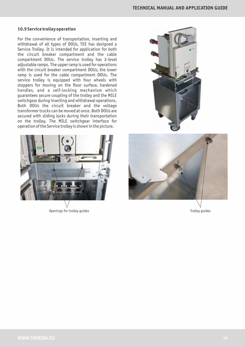
10.9 Service trolley operation
For the convenience of transportation, inserting and withdrawal of all types of DOUs, TEE has designed a Service Trolley. It is intended for application for both the circuit breaker compartment and the cable compartment DOUs. The service trolley has 2-level adjustable ramps. The upper ramp is used for operations with the circuit breaker compartment DOUs, the lower ramp is used for the cable compartment DOUs. The service trolley is equipped with four wheels with stoppers for moving on the floor surface, hardened handles, and a self-locking mechanism which guarantees secure coupling of the trolley and the MILE switchgear during inserting and withdrawal operations. Both DOUs the circuit breaker and the voltage transformer trucks can be moved at once. Both DOUs are secured with sliding locks during their transportation on the trolley. The MILE switchgear interface for operation of the Service trolley is shown in the picture.
Openings for trolley guides Trolley guides
66WWW.TAVRIDA.EU
TECHNICAL MANUAL AND APPLICATION GUIDE
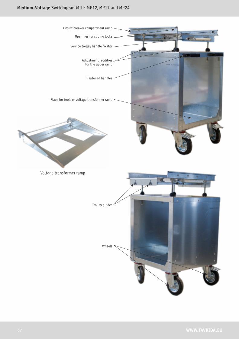
57
Openings for sliding locks
Adjustment facilities for the upper ramp
Service trolley handle fixator
Hardened handles
Place for tools or voltage transformer ramp
Wheels
Trolley guides
Circuit breaker compartment ramp
Voltage transformer ramp
67 WWW.TAVRIDA.EU
Medium-Voltage Switchgear MILE MP12, MP17 and MP24

10.9.1 Moving DOU from the removed position to the isolated position
• Adjust DOU on the service trolley• Open the door of the switchgear• Move the trolley close to the panel• Position trolley in such a way that trolley guides are
directed into the guide openings of the panel. Adjust the height of the ramp, if needed
• Push the trolley forward until the trolley guides clicks in. The trolley is secured
• In order to release DOU, slide 2 handles simultaneously to the middle
• Holding the DOU handles push DOU into the compartment until it gets stuck
• Release DOU handles. The DOU fixing blades must move into the special slots in the panel and reach the end position. Unless the DOU fixing blades are not placed correctly no operations of the DOU are possible inside the panel
• In order to remove the service trolley, release it by pressing downward the fixator handle and moving the trolley back at the same time
• When the trolley is removed, DOU is in the isolated position
Position trolley guides directed into the guide openings
Slide 2 handles simultaneously to the middle
Push DOU into the compartment until it fixes
DOU is in the test position
68WWW.TAVRIDA.EU
TECHNICAL MANUAL AND APPLICATION GUIDE

10.9.2 Moving DOU from the isolated position to the removed position
• Open the door of the switchgear• Disconnect the auxiliary plug. The DOU is in the
isolated position• Move the trolley close to the panel• Position trolley in such a way that trolley guides are
directed into the guide openings of the panel. Adjust the height of the ramp, if needed.
• Push the trolley forward until the fixator clicks. The trolley is secured.
• In order to release DOU from the compartment, slide 2 handles simultaneously to the middle
• Pull DOU backward on the trolley ramp until the DOU fixing blades click in
• Release DOU handles. The DOU fixing blades must move into the special slots of the trolley and reach the end position
• In order to remove the service trolley, press fixator handle downward and move the trolley back at the same time
• When the trolley is removed, the DOU is in the removed position
Position trolley guides directed into the guide openings
Slide 2 handles simultaneously to the middle
Pull DOU backward on the trolley ramp until the DOU fixing blades
click in
DOU is in the removed position
69 WWW.TAVRIDA.EU
Medium-Voltage Switchgear MILE MP12, MP17 and MP24

10.10 Set of tools
DOU operation tool Key for interlock of draw out unit Earth switch operation tool
10.11 Troubleshooting
Malfunction Possible origin Solution
Cannot open the cable compartment door
Earthing switch is open Check if the earthing switch is open by the indicator or through the reer window. Close the earthing switch (see chapter 10.8.1).
Cannot open the CB compartment door
CB is not in the test position Check the DOU CB position (indicator, inspection window), move DOU CB to the test position (see chapter 10.9.2).
Cannot close CB compartment door Low voltage plug of DOU is not inserted
Сheck the position of low voltage plug of DOU, insert it.
Cannot rack in the CB CB is closed Check the condition of CB, open it.
CB compartment door is open Check the position of the door, close the door.
Earthing switch is closed Check the position of the earthing switch, open it (see chapter 10.8.2).
Cannot rack out the CB CB is closed Check the condition of CB, open it.
Cannot close the earting switch CB in service or intermediate position
Check the position of CB, move it to the test position (see chapter 10.9.2)
Cannot open the earthing switch The cable compartment door is open
Check the position of cable compartment door, close it.
Cannot close CB CB is in intermediate position Check the position of CB, move CB to the test or to the service position (see chapters 10.9.2, 10.9.2).
After manual trip RESET was not performed
Press OPEN button
Blinking LED indicator „Failure” Possibly electrical interlocks are engaged
See auxiliary wiring diagram or proceed with interlock chapters of the current manual.
70WWW.TAVRIDA.EU
TECHNICAL MANUAL AND APPLICATION GUIDE

10.12 CM/TEL Malfunction detection
Code of the „Failure” LED indication
Type of malfunction
1 Power outage exceeds 1,5 s ± 0,5 s or applied voltage exceeds prescribed limit
2 Nonconformit of auxiliary contact of ISM
3 Actuator-coil is open-circuited
4 Actuator-coil is short circuited
5 Manual trip
>=6 Nonconfirmity of Module
In case the malfunction has not been determined and failure cannot be eliminated, please contact your nearest TEL office.
10.13 Opening of the cable and circuit breaker compartment doors in emergency cases. Interlock overcoming.
Two openings are placed on side of the cable and circuit breaker door.
Put M6 hex key into opening and unscrew two bolt witch hold interlocked hook.
When hook is released door can be opened.
71 WWW.TAVRIDA.EU
Medium-Voltage Switchgear MILE MP12, MP17 and MP24
LIST OF CHANGES
Medium-Voltage Switchgear MILE MP12, MP17.5 and MP24
Tavrida Electric Export rev.03 released 01.05.2011
Nr. Page number Date Author Comments
1 all pages 01.05.2011 A. Hromov All Pages, release of ver.3
72WWW.TAVRIDA.EU
TECHNICAL MANUAL AND APPLICATION GUIDE

NOTES
73 WWW.TAVRIDA.EU
Medium-Voltage Switchgear MILE MP12, MP17 and MP24

This document is copyright and is intended for users and distributors of Tavrida Electric products. It contains information that is the intellectual property of Tavrida Electric and this document, or any part thereof, should not be copied or reproduced in any form without the prior permission of Tavrida ElectricTavrida Electric applies a policy of ongoing development and reserves the right to change products without notice. Tavrida Electric does not accept any responsibility for loss or damage incurred as a result of acting or refraining from action based on information in this Catalogue.
Engineering Your Power
AS Tavrida Electric Export
ROMANIA
Energobit TAVRIDAStr. Luncii nr. 5ACod 400633 Cluj-Napoca, RomaniaTel: +40 264 207 500Fax: +40 264 207 555E-mail: [email protected]: www.tavrida.ro
UZBEKISTAN
TAVRIDA ELECTRIC UzbekistanNavoi Str. 9,100011 Tashkent Uzbekistan Tel./Fax: +998 71 150 3902E-mail: [email protected] Web: www.tavrida.uz
POLAND
Tavrida Electric Polska sp. z o.o. ul. Towarowa 23a43-100 TYCHYTel.:+48 (32) 3271986,
+48 (32) 3270737, +48 (32) 2193037
Faks:+48 (32) 3271987E-mail: [email protected]: www.tavrida.pl
E-mail: [email protected]
Tallinn Office14, Visase str.11415 Tallinn EstoniaTel: +372 606 47 57Fax: +372 606 47 59
Vilnius Office222 Ukmerges str.07157 Vilnius LithuaniaMobile: +370 68 850 680Fax: +372 606 47 59
Cairo Office25 Tayran Street (Mahmoud Shaltout),Nast City, Cairo, Egypt Tel.: +20 10 0021868Fax: +20 22 4035260E-mail: [email protected]: www.tavrida.eu
Moscow Office3rd floor, 1A, Grizodubovoy str.,125252 Moscow RussiaTel./Fax: +7 (499) 530-22-05
Your regional office


