Download - Esempi en Dsmbisp Pt

CCNA Discovery
Working at a Small-to-Medium Business or ISP
All contents are Copyright © 1992–2008 Cisco Systems, Inc. All rights reserved. This document is Cisco Public Information. Page 1 of 116
1.2.3.4: Interpreting Ping and Traceroute Output
Topology Diagram
Objectives
• Distinguish the difference between successful and unsuccessful ping attempts.
• Distinguish the difference between successful and unsuccessful traceroute attempts.
Background / Preparation
In this activity, you will test end-to-end connectivity using ping and traceroute. At the end of this activity, you will be able to distinguish the difference between successful and unsuccessful ping and traceroute attempts.
Note: Before beginning this activity, make sure that the network is converged. To converge the network quickly, switch between Simulation mode and Realtime mode until all the link lights turn green.
Step 1: Test connectivity using ping from a host computer and a router.
a. Click N-Host, click the Desktop tab, and then click Command Prompt. From the Command Prompt window, ping the Cisco server at www.cisco.com.
Packet Tracer PC Command Line 1.0
PC>ping www.cisco.com
Pinging 64.100.1.185 with 32 bytes of data:

CCNA Discovery
Working at a Small-to-Medium Business or ISP
All contents are Copyright © 1992–2008 Cisco Systems, Inc. All rights reserved. This document is Cisco Public Information. Page 2 of 116
Request timed out.
Reply from 64.100.1.185: bytes=32 time=185ms TTL=123
Reply from 64.100.1.185: bytes=32 time=281ms TTL=123
Reply from 64.100.1.185: bytes=32 time=287ms TTL=123
Ping statistics for 64.100.1.185:
Packets: Sent = 4, Received = 3, Lost = 1 (25% loss),
Approximate round trip times in milli-seconds:
Minimum = 185ms, Maximum = 287ms, Average = 251ms
PC>
b. From the output, you can see that N-Host was able to obtain an IP address for the Cisco server. The IP address was obtained using (DNS). Also notice that the first ping failed. This failure is most likely due to lack of ARP convergence between the source and destination. If you repeat the ping, you will notice that all pings succeed.
c. From the Command Prompt window on N-Host, ping E-Host at 192.168.4.10. The pings fail. If you do not want to wait for all four unsuccessful ping attempts, press Ctrl+C to abort the command, as shown below.
PC>ping 192.168.4.10
Pinging 192.168.4.10 with 32 bytes of data:
Request timed out.
Request timed out.
Ping statistics for 192.168.4.10:
Packets: Sent = 3, Received = 0, Lost = 3 (100% loss),
Control-C
^C
PC>
d. Click the N-Branch router, and then click the CLI tab. Press Enter to get the router prompt. From the router prompt, ping the Cisco server at www.cisco.com.
N-Branch>ping www.cisco.com
Translating "www.cisco.com"...domain server (64.100.1.242)
Type escape sequence to abort.
Sending 5, 100-byte ICMP Echos to 64.100.1.185, timeout is 2 seconds:
.!!!!
Success rate is 80 percent (4/5), round-trip min/avg/max = 210/211/213
ms
N-Branch>
e. As you can see, the ping output on a router is different from a PC host. Notice that the N-Branch router resolved the domain name to the same IP address that N-Host used to send its pings. Also notice that the first ping fails, which is indicated by a period (.), and that the next four pings succeed, as shown with an exclamation point (!).
f. From the CLI tab on N-Branch, ping E-Host at 192.168.4.10. Again, the pings fail. To not wait for all the failures, press Ctrl+C.

CCNA Discovery
Working at a Small-to-Medium Business or ISP
All contents are Copyright © 1992–2008 Cisco Systems, Inc. All rights reserved. This document is Cisco Public Information. Page 3 of 116
N-Branch>ping 192.168.4.10
Type escape sequence to abort.
Sending 5, 100-byte ICMP Echos to 192.168.4.10, timeout is 2 seconds:
...
Success rate is 0 percent (0/4)
N-Branch>
Step 2: Test connectivity using traceroute from a host computer and a router.
a. Click N-Host, click the Desktop tab, and then click Command Prompt. From the Command Prompt window, trace the route to the Cisco server at www.cisco.com.
PC>tracert www.cisco.com
Tracing route to 64.100.1.185 over a maximum of 30 hops:
1 92 ms 77 ms 86 ms 192.168.1.1
2 91 ms 164 ms 84 ms 64.100.1.101
3 135 ms 168 ms 151 ms 64.100.1.6
4 185 ms 261 ms 161 ms 64.100.1.34
5 257 ms 280 ms 224 ms 64.100.1.62
6 310 ms 375 ms 298 ms 64.100.1.185
Trace complete.
PC>
g. The above output shows that you can successfully trace a route all the way to the Cisco server at 64.100.1.185. Each hop in the path is a router responding three times to trace messages from N-Host. The trace continues until the destination for the trace (64.100.1.185) responds three times.
b. From the Command Prompt window on N-Host, trace a route to E-Host at 192.168.4.10. The trace fails, but notice that the tracert command traces up to 30 hops. If you do not want to wait for all 30 attempts to time out, press Ctrl+C.
PC>tracert 192.168.4.10
Tracing route to 192.168.4.10 over a maximum of 30 hops:
1 103 ms 45 ms 91 ms 192.168.1.1
2 56 ms 110 ms 125 ms 64.100.1.101
3 174 ms 195 ms 134 ms 64.100.1.6
4 246 ms 183 ms 179 ms 64.100.1.34
5 217 ms 285 ms 226 ms 64.100.1.62
6 246 ms 276 ms 245 ms 64.100.1.154
7 * * * Request timed out.
8 * * * Request timed out.
9 * * * Request timed out.
10
Control-C
^C

CCNA Discovery
Working at a Small-to-Medium Business or ISP
All contents are Copyright © 1992–2008 Cisco Systems, Inc. All rights reserved. This document is Cisco Public Information. Page 4 of 116
PC>
The tracert command can be helpful in finding the potential source of a problem. The last device to respond was 64.100.1.154, so you would start troubleshooting by determining which device is configured with the IP address 64.100.1.154. The source of the problem might not be that device, but the trace has given you a starting point, whereas a ping simply tells you that the destination is either reachable or unreachable.
c. Click the N-Branch router, and then click the CLI tab. Press Enter to get the router prompt. From the router prompt, trace the route to the Cisco server at www.cisco.com.
N-Branch>traceroute www.cisco.com
Translating "www.cisco.com"...domain server (64.100.1.242)
Type escape sequence to abort.
Tracing the route to 64.100.1.185
1 64.100.1.101 60 msec 32 msec 59 msec
2 64.100.1.6 98 msec 65 msec 65 msec
3 64.100.1.34 138 msec 147 msec 147 msec
4 64.100.1.62 189 msec 148 msec 145 msec
5 64.100.1.185 219 msec 229 msec 293 msec
N-Branch>
As you can see, traceroute output on a router is very similar to the output on a PC host. The only difference is that on a PC host, the IP address is listed after the three millisecond outputs.
d. From the CLI tab on N-Branch, trace the route to E-Host at 192.168.4.10. The trace fails at the same IP address as it failed when tracing from N-Host. Again, you can use Ctrl+C to abort the command.
N-Branch>traceroute 192.168.4.10
Type escape sequence to abort.
Tracing the route to 192.168.4.10
1 64.100.1.101 41 msec 19 msec 32 msec
2 64.100.1.6 33 msec 92 msec 117 msec
3 64.100.1.34 98 msec 102 msec 102 msec
4 64.100.1.62 166 msec 172 msec 156 msec
5 64.100.1.154 157 msec 223 msec 240 msec
6 * * *
7 * * *
8 * * *
9
N-Branch>
Step 3: Practice the ping and trace route commands.
Throughout this course, you will often use ping and traceroute to test connectivity and troubleshoot problems. To practice these commands, ping and trace from W-Host and S-Host to any other destination in the network. You can also ping and trace from N-Branch to other locations.

CCNA Discovery
Working at a Small-to-Medium Business or ISP
All contents are Copyright © 1992–2008 Cisco Systems, Inc. All rights reserved. This document is Cisco Public Information. Page 5 of 116
1.3.1.3: Identifying Equipment to Meet Customer Requirements
Topology Diagram
Objectives
• Select the appropriate interface cards for the needs and budget of an organization.
• Compare the trade-off between cost and flexibility.
• Add new equipment to accommodate expansion and allow for future growth.
Background / Preparation
An owner of a small Tier 3 ISP provides Internet access to small businesses in the area. Ten customers are starting e-commerce activities and have enquired about co-locating their web servers in the NOC facilities to provide faster access to the Internet backbone via the upstream provider. Because of the growing trend toward e-commerce, the ISP owner has decided to add co-location services to the services that they offer.
To connect customer web servers to the Internet, the ISP must purchase new routers. The ISP is deciding between using several less-expensive Cisco 1841 routers or one or two of the larger Cisco 2811 routers. You have been asked to evaluate which router model best meets the needs of the proposed co-location services and how many routers and interface cards are needed. The following requirements must be met:
• The maximum budget for routers and interface cards is $10,000 for the first year.
• The starting configuration must support 10 customer servers.
• At least 20% spare capacity must be available at all times. If the spare capacity falls below 20%, new equipment should be purchased.
• A 20% growth rate in the demand for co-location services is expected each quarter (every three months).
• Two serial ports must be available to connect to the upstream ISP. To ensure that backup routes are available, each router needs to have its own connection to the upstream provider.
Your task is to recommend the solution that best meets the requirements for the first year while staying within the maximum budget of $10,000. For the purposes of this exercise, use the following equipment costs.
• 1841 router – $1,500
• 2811 router – $2,500
• HWIC-4ESW four-port Ethernet switch card – $500
• WIC-2T two-port serial interface card – $700
• NM-ESW-161 16-port Ethernet switching network module – $1500
CCNA Discovery
Working at a Small-to-Medium Business or ISP
All contents are Copyright © 1992–2008 Cisco Systems, Inc. All rights reserved. This document is Cisco Public Information. Page 6 of 116
Note: This activity begins by showing 100% completion, because the purpose is to only demonstrate the process used to design and plan a network upgrade. This activity is not graded.
Step 1: Evaluate the scalability of the Cisco 1841 router.
a. Click the 1841 router in the workspace area.
b. On the Physical tab, in the Physical Device View window, click the power switch to turn off the router.
c. Click each module in the Modules column and read its description in the box below the router.
d. Which module provides the most Ethernet ports? How many ports does it have?
________________________________________________________________
e. Drag the module with the most Ethernet ports to an empty slot on the router in the Physical Device View window.
f. Which module provides the most serial ports? How many ports does it have?
________________________________________________________________
g. Drag the module with the most serial ports to an empty slot on the router.
Click the power switch to turn on the router.
________________________________________________________________
h. The remaining questions in the handout for Step 1 will help you evaluate the scalability of the 1841 router.
________________________________________________________________
i. Using the configuration from Step g, what would be the total cost to purchase this router?
________________________________________________________________
j. How many 1841 routers are needed to support the initial 10 customer servers? What is the total cost?
________________________________________________________________
k. How many spare ports does this equipment provide? Does this number meet the requirement for 20% growth?
________________________________________________________________
l. Fill out the expense sheet in Handout A with the necessary equipment and costs for each quarter of operation, assuming a 20% growth every quarter. (Hint: Round up to the nearest whole number. For example, if a 20% growth is 2.4 servers, plan to support 3 new servers.)
m. Based on your expense sheet calculations, how soon will another 1841 router need to be purchased?
________________________________________________________________
n. How much equipment can be purchased before the initial budget of $10,000 is spent?
________________________________________________________________
o. How many customer servers can be supported within the initial equipment budget?
________________________________________________________________
Step 2: Evaluate the scalability of the Cisco 2811 router.
a. Click the 2811 router in the workspace area.
CCNA Discovery
Working at a Small-to-Medium Business or ISP
All contents are Copyright © 1992–2008 Cisco Systems, Inc. All rights reserved. This document is Cisco Public Information. Page 7 of 116
b. On the Physical tab, in the Physical Device View window, click the power switch to turn off the router.
c. Click each module in the Modules column and read its description in the box below the router. The modules with names that begin with NM are network modules. The modules with names that begin with HWIC or WIC are interface cards.
d. Which network module provides the most Ethernet ports? How many ports does it have?
________________________________________________________________
e. Drag the network module with the most Ethernet ports to the empty network module slot on the router in the Physical Device View window. The network module slot is the larger slot on the left side of the router.
f. How many empty interface card slots (smaller slots) are available? (Write your answer on the handout.)
________________________________________________________________
g. Which interface card provides the most Ethernet ports? How many ports does it have? (Write your answers on the handout.)
________________________________________________________________
h. Drag the interface card with the most Ethernet ports to three of the four remaining slots on the router.
i. Which interface card provides the most serial ports? How many ports does it have? (Write your answers on the handout.)
________________________________________________________________
j. Drag the interface card with the most serial ports to the empty slot on the router.
k. The 2811 router comes with two Fast Ethernet ports, in addition to the ports provided by the modules. Assuming one Ethernet port is used per customer server, what is the maximum number of servers that one 2811 router can support with the added modules?
________________________________________________________________
l. A 20% growth needs to be provided? How many ports are set aside to accommodate this growth?
________________________________________________________________
m. What is the total cost of this configuration
________________________________________________________________
n. How many 2811 routers are needed to support the initial 10 customer servers? What is the total cost?
________________________________________________________________
o. How many spare ports does this initial equipment provide? Does this number meet the requirement for 20% growth?
________________________________________________________________
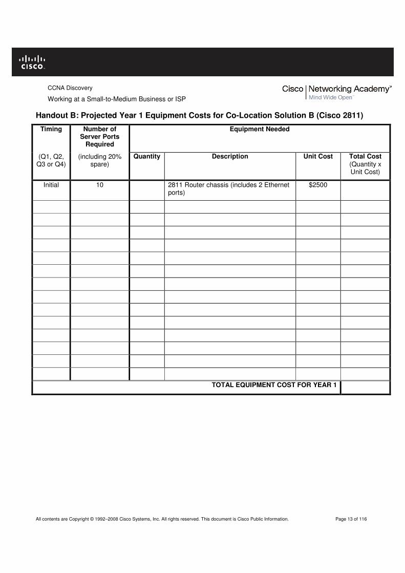
p. Fill out the expense sheet in Handout B with the necessary equipment and costs for each quarter of operation, assuming a 20% growth every quarter. (Hint: Round up to the nearest whole number. For example, if a 20% growth is 2.4 servers, plan to support 3 new servers.)
q. Based on your expense sheet calculations, how soon will another 2811 router need to be purchased?
________________________________________________________________
________________________________________________________________

CCNA Discovery
Working at a Small-to-Medium Business or ISP
All contents are Copyright © 1992–2008 Cisco Systems, Inc. All rights reserved. This document is Cisco Public Information. Page 8 of 116
r. How much equipment can be purchased before the initial budget of $10,000 is spent
________________________________________________________________
s. How many customer servers can be supported within the initial equipment budget?
________________________________________________________________
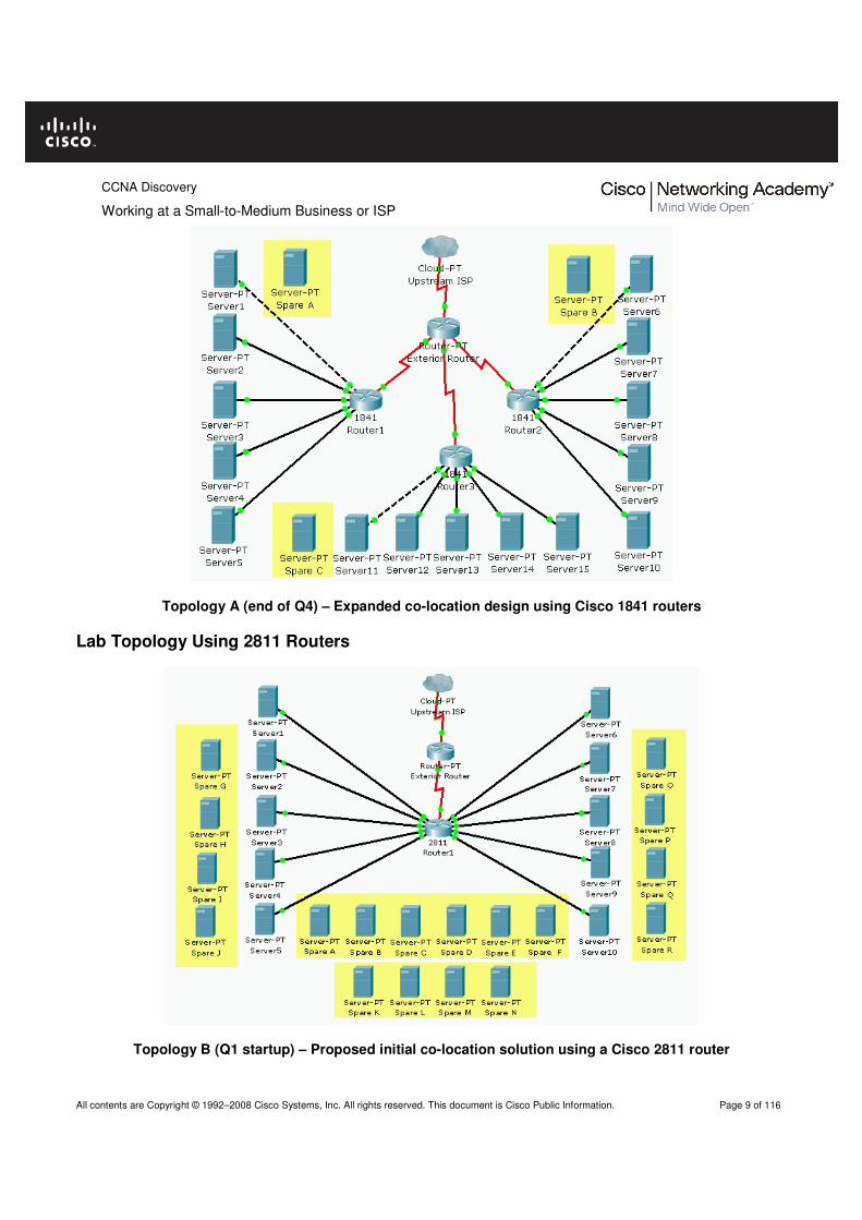
The following diagrams represent the initial and final network topologies for both the 1841 and 2811 routers. These topologies will help determine the best solution for meeting both the current and future needs while still remaining within budge
Lab Topology Using 1841 Routers
Topology A (Q1 startup) – Proposed initial co-location solution using Cisco 1841 routers
CCNA Discovery
Working at a Small-to-Medium Business or ISP
All contents are Copyright © 1992–2008 Cisco Systems, Inc. All rights reserved. This document is Cisco Public Information. Page 9 of 116
Topology A (end of Q4) – Expanded co-location design using Cisco 1841 routers
Lab Topology Using 2811 Routers
Topology B (Q1 startup) – Proposed initial co-location solution using a Cisco 2811 router

CCNA Discovery
Working at a Small-to-Medium Business or ISP
All contents are Copyright © 1992–2008 Cisco Systems, Inc. All rights reserved. This document is Cisco Public Information. Page 10 of 116
Topology B (end of Q4) – Expanded co-location solution using a Cisco 2811 router
Step 3: Recommend a co-location solution
a. Based on your evaluations of the 1841 and 2811 router, which solution would you recommend to provide the best scalability while staying within the budget limitations? Explain the reasons for your choice?
____________________________________________________________________________
____________________________________________________________________________
____________________________________________________________________________
____________________________________________________________________________
b. What other solutions could be considered?
____________________________________________________________________________
____________________________________________________________________________
Step 4: Reflection
a. Whenever new equipment is added to a co-location rack, the rack must be powered down. This causes a loss of service to all the existing customers on that rack. If this happens too often, customers will switch to another provider. Based on your experiences with the 1841 and 2811 router

CCNA Discovery
Working at a Small-to-Medium Business or ISP
All contents are Copyright © 1992–2008 Cisco Systems, Inc. All rights reserved. This document is Cisco Public Information. Page 11 of 116
configurations, which solution would minimize network downtime? Explain the reasons for your choice?
____________________________________________________________________________
____________________________________________________________________________
____________________________________________________________________________
b. Network availability and reliability is of great importance to e-commerce businesses. What would happen to the Internet access of the customer web servers if one of the routers in the co-location network failed? Which solution would negatively affect the most customers if a co-location router failed?
____________________________________________________________________________
____________________________________________________________________________
____________________________________________________________________________
c. What could be done to improve the reliability of the co-location network and to minimize downtime?
____________________________________________________________________________
____________________________________________________________________________
____________________________________________________________________________

CCNA Discovery
Working at a Small-to-Medium Business or ISP
All contents are Copyright © 1992–2008 Cisco Systems, Inc. All rights reserved. This document is Cisco Public Information. Page 12 of 116
Handout A: Projected Year 1 Equipment Costs for Co-Location Solution A (Cisco 1841)
Timing Number of Server Ports
Required
Equipment Needed
(Q1, Q2, Q3 or Q4)
(including 20% spare)
Quantity Description Unit Cost Total Cost (Quantity x Unit Cost)
Initial 10 1841 Router chassis (includes 2 Ethernet ports)
$1500
TOTAL EQUIPMENT COST FOR YEAR 1
CCNA Discovery
Working at a Small-to-Medium Business or ISP
All contents are Copyright © 1992–2008 Cisco Systems, Inc. All rights reserved. This document is Cisco Public Information. Page 13 of 116
Handout B: Projected Year 1 Equipment Costs for Co-Location Solution B (Cisco 2811)
Timing Number of Server Ports
Required
Equipment Needed
(Q1, Q2, Q3 or Q4)
(including 20% spare)
Quantity Description Unit Cost Total Cost (Quantity x Unit Cost)
Initial 10 2811 Router chassis (includes 2 Ethernet ports)
$2500
TOTAL EQUIPMENT COST FOR YEAR 1

CCNA Discovery
Working at a Small-to-Medium Business or ISP
All contents are Copyright © 1992–2008 Cisco Systems, Inc. All rights reserved. This document is Cisco Public Information. Page 14 of 116
2.3.1.4: Troubleshooting and Resolving Network Issues
Topology Diagram
Objectives
• Diagnose a network connectivity issue.
• Implement a proposed solution to restore network connectivity.
Background / Preparation
You are working at the help desk. A customer reports that they cannot reach the Discovery server from PC 1A. The customer has another computer on the same network as PC 1A. You have consoled into the router and verified that all the interfaces are up.
Step 1: Diagnose the problem.
a. Check the connectivity to the Discovery server at 192.168.3.77 from both PC 1A and PC 1B using the ping command. Note: The ping can be issued in either Realtime or Simulation mode. The first pings might time out because the PCs need to complete the ARP process.
b. View the configuration of both PCs, and note any potential issues.
Step 2: Troubleshoot the problem.
A difference in default gateways has been found between the two PCs. Make the necessary configuration changes to restore connectivity.
CCNA Discovery
Working at a Small-to-Medium Business or ISP
All contents are Copyright © 1992–2008 Cisco Systems, Inc. All rights reserved. This document is Cisco Public Information. Page 15 of 116
Step 3: Test the solution.
a. Ping from both PCs to verify connectivity to the Discovery server. Pings from both PCs should succeed.
b. Click the Check Results button at the bottom of this instruction window to check your work.
Reflection
What else could have caused connectivity problems on this network?
CCNA Discovery
Working at a Small-to-Medium Business or ISP
All contents are Copyright © 1992–2008 Cisco Systems, Inc. All rights reserved. This document is Cisco Public Information. Page 16 of 116
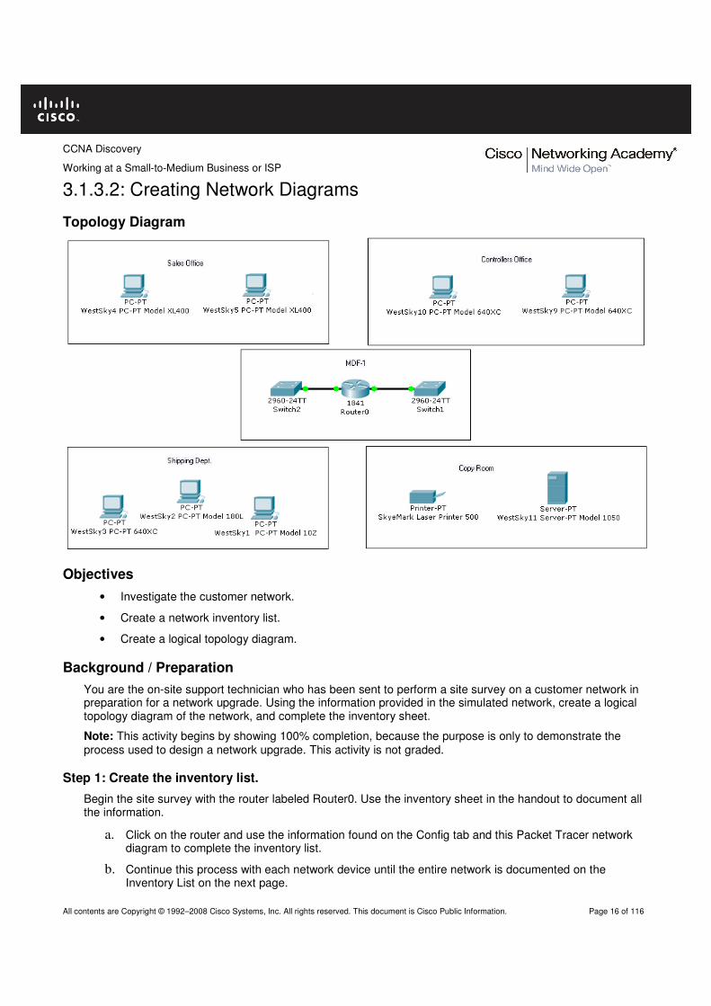
3.1.3.2: Creating Network Diagrams
Topology Diagram
Objectives
• Investigate the customer network.
• Create a network inventory list.
• Create a logical topology diagram.
Background / Preparation
You are the on-site support technician who has been sent to perform a site survey on a customer network in preparation for a network upgrade. Using the information provided in the simulated network, create a logical topology diagram of the network, and complete the inventory sheet.
Note: This activity begins by showing 100% completion, because the purpose is only to demonstrate the process used to design a network upgrade. This activity is not graded.
Step 1: Create the inventory list.
Begin the site survey with the router labeled Router0. Use the inventory sheet in the handout to document all the information.
a. Click on the router and use the information found on the Config tab and this Packet Tracer network diagram to complete the inventory list.
b. Continue this process with each network device until the entire network is documented on the Inventory List on the next page.

CCNA Discovery
Working at a Small-to-Medium Business or ISP
All contents are Copyright © 1992–2008 Cisco Systems, Inc. All rights reserved. This document is Cisco Public Information. Page 17 of 116
Note: All PCs and servers are running Linux, and all Cisco devices are running Cisco IOS software. The connectivity for the PCs can be found using the show running-config command on the switches.
Example
Device Name
Location Brand and Model
Operating System
*All Cisco devices use IOS
IP Addresses Connectivity
R14 MDF-1 Cisco 2621 IOS FA0/0 192.168.10.10/24
FA0/1
172.16.10.10/24
100 MB Ethernet to Switch 1
100 MB Ethernet to Switch 2

CCNA Discovery
Working at a Small-to-Medium Business or ISP
All contents are Copyright © 1992–2008 Cisco Systems, Inc. All rights reserved. This document is Cisco Public Information. Page 18 of 116
Inventory List
Device Name
Location Brand and Model
Operating System
*All Cisco devices use IOS
IP Addresses Connectivity

CCNA Discovery
Working at a Small-to-Medium Business or ISP
All contents are Copyright © 1992–2008 Cisco Systems, Inc. All rights reserved. This document is Cisco Public Information. Page 19 of 116
Step 2: Draw the logical topology diagram.
Use the information collected on the inventory sheet and the Packet Tracer network diagram to draw a logical network diagram of the customer network.
Logical Topology Diagram

CCNA Discovery
Working at a Small-to-Medium Business or ISP
All contents are Copyright © 1992–2008 Cisco Systems, Inc. All rights reserved. This document is Cisco Public Information. Page 20 of 116
3.3.3.4: Exploring Different LAN Switch Options
Topology Diagram
Objectives
• Determine the cable types to use to connect all devices to the switch.
• Add appropriate modules to switches and routers.
• Connect the devices to the switch using the appropriate cable types.
Background / Preparation
The results of a site survey for an ISP customer indicate that the customer needs to upgrade the LAN to include a new standalone switch. The network has an existing router (Router0) and a Linksys 300N router. It is necessary to determine which interfaces are needed on the new switch to provide connectivity to the router, the Linksys device, and the customer PCs. The customer wants to use copper cabling.
Note: Links created with the switch may take a minute to change from amber to green. Switch between Simulation mode and Realtime mode to speed up this process.
Step 1: Determine the required connectivity options.
a. Click Router0. Using the information in the Physical Device View window on the Physical tab, determine what type of interface is available on the router to connect to the new switch.
Hint: Place the mouse pointer on the interface to display the interface type. Click on the interface type to display a description of the interface.
b. Which interface is available on the router to connect to the new switch? What type of cable is required?
________________________________________________________________
c. Click the Linksys 300N. Using the picture on the Physical tab, determine what type of cable is necessary to connect to the new switch.
d. Which interface is available on the Linksys 300N to connect to the new switch? What type of cable is required?
CCNA Discovery
Working at a Small-to-Medium Business or ISP
All contents are Copyright © 1992–2008 Cisco Systems, Inc. All rights reserved. This document is Cisco Public Information. Page 21 of 116
________________________________________________________________
Step 2: Configure the new switch with the required options.
a. Click Switch0.
b. On the Physical tab, explore each switch module available under the Modules option.
c. Choose the appropriate interfaces to connect to Router0 and the Linksys 300N router.
d. Choose the appropriate interfaces to connect to the existing PCs.
e. Power down the switch using the power button in the Physical Device View window on the Physical tab.
f. Choose the appropriate modules for the switch. Add the four necessary interfaces to the switch.
g. Power up the switch using the power button shown in the Physical Device View window on the Physical tab.
h. Click the Config tab. Select each interface and ensure that the On box is checked.
Step 3: Connect the router to the switch.
a. Using the appropriate cable, connect the router port to the first available switch port. Click the Config tab on the router. Select the interface and ensure that the On box is checked.
b. Verify connectivity. A green light appears on each end of the link if the cabling is correct.
Step 4: Connect the Linksys 300N to the switch.
a. Using the appropriate cable, connect the Linksys 300N to the second available port on the new switch.
b. Verify connectivity. A green light appears on each end of the link if the cabling is correct.
Step 5: Connect the PCs to the switch.
a. Using the appropriate cable, connect the existing PCs to the new switch.
b. Verify connectivity. A green light appears on each end of the links if the cabling is correct.
c. Click the Check Results button at the bottom of this instruction window to check your work.
CCNA Discovery
Working at a Small-to-Medium Business or ISP
All contents are Copyright © 1992–2008 Cisco Systems, Inc. All rights reserved. This document is Cisco Public Information. Page 22 of 116
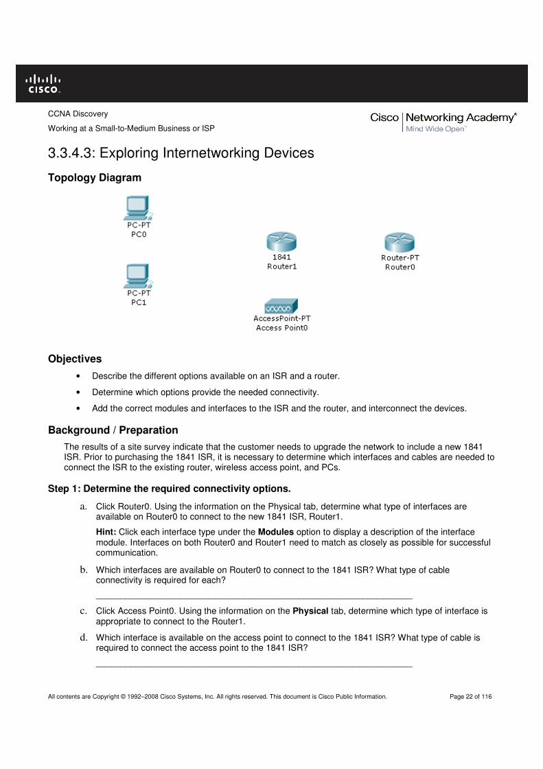
3.3.4.3: Exploring Internetworking Devices
Topology Diagram
Objectives
• Describe the different options available on an ISR and a router.
• Determine which options provide the needed connectivity.
• Add the correct modules and interfaces to the ISR and the router, and interconnect the devices.
Background / Preparation
The results of a site survey indicate that the customer needs to upgrade the network to include a new 1841 ISR. Prior to purchasing the 1841 ISR, it is necessary to determine which interfaces and cables are needed to connect the ISR to the existing router, wireless access point, and PCs.
Step 1: Determine the required connectivity options.
a. Click Router0. Using the information on the Physical tab, determine what type of interfaces are available on Router0 to connect to the new 1841 ISR, Router1.
Hint: Click each interface type under the Modules option to display a description of the interface module. Interfaces on both Router0 and Router1 need to match as closely as possible for successful communication.
b. Which interfaces are available on Router0 to connect to the 1841 ISR? What type of cable connectivity is required for each?
________________________________________________________________
c. Click Access Point0. Using the information on the Physical tab, determine which type of interface is appropriate to connect to the Router1.
d. Which interface is available on the access point to connect to the 1841 ISR? What type of cable is required to connect the access point to the 1841 ISR?
________________________________________________________________

CCNA Discovery
Working at a Small-to-Medium Business or ISP
All contents are Copyright © 1992–2008 Cisco Systems, Inc. All rights reserved. This document is Cisco Public Information. Page 23 of 116
Hint: The access point is a similar type of device to the router and requires the same type of cable used to connect like devices.
Step 2: Configure the new 1841 ISR, Router 1, with the required options.
a. Click Router1. Explore the ISR modules available under the Modules option on the Physical tab.
b. Find the appropriate interface modules to connect to Router0, Access Point0, and the existing PCs.
Note: The module names might not be the same as those installed on the existing networking equipment. Choose modules that provide the same kind of connectivity, and use the same type of cable.
c. What types of interface modules are available for the 1841 ISR? Which Ethernet or serial interfaces are built into the 1841 ISR?
________________________________________________________________
For this network, the multiport switch module is the best choice to connect the PCs. The built-in LAN ports can be used to connect to the access point.
d. Power down the 1841 ISR using the power button in the Physical Device View window on the Physical tab.
e. Add the appropriate modules to the 1841 ISR. Place the module that connects to Router0 in the slot on the right (Slot 0), and place the multiport switch module in the slot on the left (Slot 1).
Note: The modules can be used in either slot. However, to ensure correct grading in Packet Tracer place the modules as instructed.
f. Power up the 1841 ISR using the power button in the Physical Device View window on the Physical tab.
g. Go to the Config tab and select each interface. Check the On box to power up the interfaces.
h. Ensure that all interfaces are on.
Step 3: Connect Router0 to the 1841 ISR, Router1.
a. Router0 connects Router1 over a wide area network. Using the appropriate cable, connect the first appropriate Router0 port to the first available Router1 port.
b. Verify that the connection is working. A green link light at each end of the cable indicates that the correct cable type is being used and that the interfaces are powered up.
Step 4: Connect the access point to the 1841 ISR, Router 1.
a. Using the appropriate cable, connect the access point to the 1841 ISR. Connect the access point to the first built-in LAN port on the 1841 ISR.
b. Verify that the connection is working. A green link light at each end of the cable indicates that the correct cable type is being used and that the interfaces are powered up.
Step 5: Connect the PCs to the 1841 ISR.
a. Using the appropriate cable, connect the existing PCs to the new 1841 ISR. Connect PC0 to the first port on the four-port switch module. It appears in the interface list as FastEthernet 0/1/0. Connect PC1 to the second port.

CCNA Discovery
Working at a Small-to-Medium Business or ISP
All contents are Copyright © 1992–2008 Cisco Systems, Inc. All rights reserved. This document is Cisco Public Information. Page 24 of 116
Note: The built-in Fast Ethernet LAN interfaces (Fast Ethernet 0/0 and Fast Ethernet 0/1) on the 1841 ISR are not appropriate for connecting individual PCs.
b. Verify that the connection is working. A green link light at each end of the cable indicates that the correct cable type is being used and that the interfaces are powered up. The link lights at Router1 are amber for approximately 30 seconds before turning green.
c. Click the Check Results button at the bottom of this instruction window to check your work.

CCNA Discovery
Working at a Small-to-Medium Business or ISP
All contents are Copyright © 1992–2008 Cisco Systems, Inc. All rights reserved. This document is Cisco Public Information. Page 25 of 116
4.1.3.5: Implementing an IP Addressing Scheme
Topology Diagram
Objectives
• Subnet an address space based on the host requirements.
• Assign host addresses to devices.
• Configure devices with IP addressing.
• Verify the addressing configuration.
Background / Preparation
In this activity, you will subnet the private address space 192.168.1.0/24 to provide enough host addresses for the two LANs attached to the router. You will then assign valid host addresses to the appropriate devices and interfaces. Finally, you will test connectivity to verify your IP address implementation.
Step 1: Subnet an address space based on the host requirements.
a. You are given the private address space 192.168.1.0/24. Subnet this address space based on the following requirements:
• LAN-A needs enough addresses for 50 hosts.
• LAN-B needs enough addresses for 40 hosts.
b. How many bits must be left for host addresses? _____
c. How many bits can now be taken from the host portion to make a subnet? _____
d. How many hosts does each subnet support? _____
e. How many subnets are created? _____
f. What is the new subnet mask? ______________________________
Step 2: Assign host addresses to devices.
a. What is the subnet address for subnet 0? ______________________________
CCNA Discovery
Working at a Small-to-Medium Business or ISP
All contents are Copyright © 1992–2008 Cisco Systems, Inc. All rights reserved. This document is Cisco Public Information. Page 26 of 116
b. What is the subnet address for subnet 1? ______________________________
c. Assign subnet 0 to LAN-A, and assign subnet 1 to LAN-B.
d. What is the first address in subnet 0? ______________________________ This address is assigned the FastEthernet0/0 interface on Customer Router.
e. What is the first address in subnet 1? ______________________________ This address is assigned the FastEthernet0/1 interface on Customer Router.
f. What is the last address in subnet 0? ______________________________ This address is assigned to HostA.
g. What is the last address in subnet 1? ______________________________ This address is assigned to HostB.
h. What is the default gateway for HostA? ______________________________
i. What is the default gateway for HostB? ______________________________
Step 3: Configure devices with IP addressing.
Configure HostA and HostB with IP addressing, including the subnet mask and default gateway.
a. Click HostA. On the Desktop tab, choose IP Configuration. Enter the correct addressing for HostA according to your answers in Step 1 and Step 2.
b. Click HostB. On the Desktop tab, choose IP Configuration. Enter the correct addressing for HostB according to your answers in Step 1 and Step 2.
c. Check results. On the Assessment Items tab, your configurations for HostA and HostB should have green checkmarks. If not, read the provided feedback for a hint on how to correct the problem.
Note: If you cannot see all the feedback, place your mouse pointer over the right side of the Activity Results window. When the cursor turns into a double-headed arrow, click and drag to resize the window until you can see all the feedback text.)
Configure the LAN interfaces on Customer Router with IP addresses and a subnet mask.
a. Click Customer Router. Click the Config tab.
b. On the left side under Interface, click FastEthernet0/0. Enter the IP address and subnet mask, and then set the Port Status to On.
c. On the left side under Interface, click FastEthernet0/1. Enter the IP address and subnet mask, and then set the Port Status to On.
d. Notice in the Equivalent IOS Commands window that your actions produced actual commands. You can scroll through the command window. In the next chapter, you will learn how to enter these commands directly into the router instead of using the Config tab. For a better view of the commands, you can increase the size of the window. To resize the window, place your mouse pointer over the bottom border of the window. When the cursor turns into a double-headed arrow, click and drag.
e. Check results. On the Assessment Items tab, your configurations for Customer Router should have green checkmarks. If not, read the provided feedback for a hint on how to correct the problem.
CCNA Discovery
Working at a Small-to-Medium Business or ISP
All contents are Copyright © 1992–2008 Cisco Systems, Inc. All rights reserved. This document is Cisco Public Information. Page 27 of 116
Step 4: Verify the addressing configuration.
a. Test connectivity between HostA, HostB, ISP Workstation, and ISP Server. You can use the Add Simple PDU tool to create pings between the devices. You can also click HostA or HostB, then the Desktop tab, and then Command Prompt. Use the ping command to test connectivity to other devices. To obtain the IP address of another device, place your mouse pointer over the device.
b. Check results. On the Connectivity Tests tab, the status of each test should be successful.
Reflection
a. How many subnets are still available for future expansion?
b. What would be the two subnet addresses if the host requirement was 80 hosts per LAN?
c. Challenge: Create your own Packet Tracer network using the same topology, but implement an addressing scheme based on 80 hosts per LAN. Have another student or your instructor check your work.

CCNA Discovery
Working at a Small-to-Medium Business or ISP
All contents are Copyright © 1992–2008 Cisco Systems, Inc. All rights reserved. This document is Cisco Public Information. Page 28 of 116
4.1.5.2: Communicating Between Subnets
Topology Diagram
Objectives
• Describe how hosts on separate subnets communicate to share resources.
Background / Preparation
This activity demonstrates how to configure devices on different subnets so that they can communicate with each other. It is important that the devices and the routers connecting subnets have the correct IP address.
Step 1: Determine if myPC can reach myServer and myRouter.
a. From the command prompt on myPC, ping 192.168.1.45 to reach myServer, and ping 192.168.1.33 to reach myRouter. Were the ping attempts successful? _______
b. In Packet Tracer, roll over each device (myPC, myServer, and myRouter) with your mouse pointer and inspect the information that appears.
c. Record the IP address and subnet mask of each device in the following table.
d. Determine if the devices are all in the same subnet, or if they are in different subnets.
Device Interface IP Address Subnet Mask Subnet Default Gateway
myPC Fast Ethernet
myServer Fast Ethernet
myRouter Fast Ethernet 0/0
e. Is myPC in the same subnet as myServer and the Fast Ethernet 0/0 interface of myRouter? _______

CCNA Discovery
Working at a Small-to-Medium Business or ISP
All contents are Copyright © 1992–2008 Cisco Systems, Inc. All rights reserved. This document is Cisco Public Information. Page 29 of 116
Step 2: Configure the network to allow myPC to reach myServer.
On the Config tab on myPC, assign the second usable address in the subnet used for the LAN supported by myRouter to myPC.
Step 3: Verify connectivity.
a. After changing the IP address on myPC, ping 192.168.1.45 to reach myServer, and ping 192.168.1.33 to reach myRouter. The pings should be successful.
b. Click the Check Results button at the bottom of this instruction window to check your work.
Reflection
a. Why was myPC unable to communicate with myServer at the beginning of this activity?
b. This exercise demonstrates how subnetting affects which devices can communicate on a network.
CCNA Discovery
Working at a Small-to-Medium Business or ISP
All contents are Copyright © 1992–2008 Cisco Systems, Inc. All rights reserved. This document is Cisco Public Information. Page 30 of 116
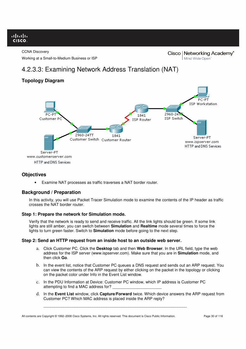
4.2.3.3: Examining Network Address Translation (NAT)
Topology Diagram
Objectives
• Examine NAT processes as traffic traverses a NAT border router.
Background / Preparation
In this activity, you will use Packet Tracer Simulation mode to examine the contents of the IP header as traffic crosses the NAT border router.
Step 1: Prepare the network for Simulation mode.
Verify that the network is ready to send and receive traffic. All the link lights should be green. If some link lights are still amber, you can switch between Simulation and Realtime mode several times to force the lights to turn green faster. Switch to Simulation mode before going to the next step.
Step 2: Send an HTTP request from an inside host to an outside web server.
a. Click Customer PC. Click the Desktop tab and then Web Browser. In the URL field, type the web address for the ISP server (www.ispserver.com). Make sure that you are in Simulation mode, and then click Go.
b. In the event list, notice that Customer PC queues a DNS request and sends out an ARP request. You can view the contents of the ARP request by either clicking on the packet in the topology or clicking on the packet color under Info in the Event List window.
c. In the PDU Information at Device: Customer PC window, which IP address is Customer PC attempting to find a MAC address for? ______________________
d. In the Event List window, click Capture/Forward twice. Which device answers the ARP request from Customer PC? Which MAC address is placed inside the ARP reply?
________________________________________________________________
CCNA Discovery
Working at a Small-to-Medium Business or ISP
All contents are Copyright © 1992–2008 Cisco Systems, Inc. All rights reserved. This document is Cisco Public Information. Page 31 of 116
e. In the Event List window, click Capture/Forward twice. Customer PC accepts the ARP replay and then builds another packet. What is the protocol for this new packet? If you click Outbound PDU Details for this packet, you can see the details of the protocol. _________
f. In the Event List window, click Capture/Forward twice. Click the packet at the www.customerserver.com server. Then click the Outbound PDU Details tab. Scroll down to the bottom to see the Application Layer data. What is the IP address for the ISP server?
________________________________________________________________
g. In the Event List window, click Capture/Forward twice. Customer PC now formulates another ARP request. Why?
________________________________________________________________
h. In the Event List window, click Capture/Forward 10 times until Customer PC formulates an HTTP request packet. Customer PC finally has enough information to request a web page from the ISP server.
i. In the Event List window, click Capture/Forward three times. Click the packet at Customer Router to examine the contents. Customer Router is a NAT border router. What is the inside local address and the inside global address for Customer PC?
________________________________________________________________
j. In the Event List window, click Capture/Forward seven times until the HTTP reply reaches Customer Router. Examine the contents of the HTTP reply and notice that the inside local and global addresses have changed again as the packet is forwarded on to Customer PC.
Step 3: Send an HTTP request from an outside host to an inside web server.
Customer Server provides web services to the public (outside addresses) through the domain name www.customerserver.com. Follow a process similar to Step 2 to observe an HTTP request on ISP Workstation.
a. Click ISP Workstation. Click the Desktop tab, and then Web Browser. In the URL field, type the Customer Server web address (www.customerserver.com). Make sure that you are in Simulation mode, and then click Go.
b. You can either click Auto Capture/Play or Capture/Forward to step through each stage of the process. The same ARP and DNS processes occur before the ISP Workstation can formulate an HTTP request.
c. When the HTTP request arrives at Customer Router, check the packet contents. What is the inside local address? What is the inside global address?
________________________________________________________________
CCNA Discovery
Working at a Small-to-Medium Business or ISP
All contents are Copyright © 1992–2008 Cisco Systems, Inc. All rights reserved. This document is Cisco Public Information. Page 32 of 116
5.3.2.5: Exploring the Cisco IOS CLI
Topology Diagram
Objectives
• Use the Cisco IOS CLI context-sensitive Help feature.
• Explore command shortcuts.
• Learn about error detection features.
• Use command history.
Background / Preparation
The Cisco IOS CLI includes many features that help in recalling commands and getting information about command use and function. In this activity, you will explore some of these features and perhaps discover why network technicians prefer the Cisco IOS CLI.
Note: This activity begins by showing 100% completion, because the purpose is only to explore the Cisco IOS CLI. This activity is not graded.
Step 1: Connect to the Customer Cisco 1841 router.
Use the terminal emulation software on Customer PC to connect to the Cisco 1841 Customer Router. Press Enter to get started. The CustomerRouter> prompt indicates that you are in user EXEC mode.
Step 2: Explore the context-sensitive Help feature.
a. At the router command prompt, type ?. A brief description of the help that is available is displayed.
b. Type e? to see which commands start with the letter “e”.
c. Type en?. Notice that you see only commands that start with “en”.
d. Type enable. The prompt changes to CustomerRouter#, indicating that you are in privileged EXEC mode.
Step 3: Explore Cisco IOS command shortcuts.
If you type letters that are unique to a command and then press the Tab key, the CLI automatically spells out the complete command.
a. Type c at the CustomerRouter# prompt and press the Tab key. Because “c” by itself is not unique to just one command, nothing happens.
b. Now add “onf” to the “c” and press the Tab key. Because this sequence of letters is unique to the configure command, the CLI automatically completes the command entry.
CCNA Discovery
Working at a Small-to-Medium Business or ISP
All contents are Copyright © 1992–2008 Cisco Systems, Inc. All rights reserved. This document is Cisco Public Information. Page 33 of 116
c. Now type ? after “configure”. A list of parameters and options for the configure command are displayed. The <cr> at the end of the output indicates that there are no other parameters that can be added to the configure command in this mode. In this example, the CLI shows that you can use terminal with the configure command: configure terminal.
Step 4: Explore error detection features.
a. At the CustomerRouter# prompt, type con and then press Enter. The output % Ambiguous command: "con" indicates that this is an incomplete command.
b. At the router command prompt, enter configure trminal and then press Enter. Be sure to enter the command with the spelling error. The Cisco IOS CLI does not recognize the command and indicates an error with the marker ^.
Step 5: Recall previously typed commands.
a. Previously used commands are stored in a history buffer. To recall the last command entered, press Ctrl-P. The command appears at the router command prompt.
b. Scroll back through the commands in the history buffer by repeatedly pressing Ctrl-P, and then press Ctrl-N to cycle forward through the history buffer. The Up and Down Arrow keys can also be used to recall commands from the history buffer.
c. To view the last 10 commands entered, enter the show history command.
Reflection
a. List two Cisco IOS CLI commands that are available from the CustomerRouter# prompt but that are not available from the CustomerRouter> prompt.
Tip: Type enable to change to the CustomerRouter# prompt, and type disable to return to the CustomerRouter> prompt.
b. What does <cr> indicate at the end of a list of commands after you have requested help?

CCNA Discovery
Working at a Small-to-Medium Business or ISP
All contents are Copyright © 1992–2008 Cisco Systems, Inc. All rights reserved. This document is Cisco Public Information. Page 34 of 116
5.3.3.3: Using the Cisco IOS Show Commands
Topology Diagram
Objectives
• Use the Cisco IOS show commands.
Background / Preparation
The Cisco IOS show commands are used extensively when working with Cisco equipment. In this activity, you will use the show commands on a router that is located at an ISP.
Note: This activity begins by showing 100% completion, because the purpose is only to explore the Cisco IOS show commands. This activity is not graded.
Step 1: Connect to the ISP Cisco 1841 router.
Use the terminal emulation software on ISP PC to connect to the Cisco 1841 router. The ISPRouter> prompt indicates that you are in user EXEC mode. Now type enable at the prompt. The ISPRouter# prompt indicates that you are in privileged EXEC mode.
Step 2: Explore the show commands.
Use the information displayed by these show commands to answer the questions in the Reflection section.
a. Type show arp.
b. Type show flash.
c. Type show ip route.
d. Type show interfaces.
e. Type show protocols.
f. Type show users.
g. Type show version.
CCNA Discovery
Working at a Small-to-Medium Business or ISP
All contents are Copyright © 1992–2008 Cisco Systems, Inc. All rights reserved. This document is Cisco Public Information. Page 35 of 116
Reflection
a. Why do you need to be in privileged EXEC mode to explore the Cisco IOS show commands that were used in this activity?
b. How much flash memory is reported?
c. Which of the following is subnetted?
• 209.165.201.0
• 209.165.201.1
• 209.165.201.10
d. Which interface is up and running?
• Serial0/1/0
• FastEthernet0/1
• FastEthernet0/0
• VLAN1

CCNA Discovery
Working at a Small-to-Medium Business or ISP
All contents are Copyright © 1992–2008 Cisco Systems, Inc. All rights reserved. This document is Cisco Public Information. Page 36 of 116
5.3.4.4: Performing an Initial Router Configuration
Topology Diagram
Objectives
• Configure the router host name.
• Configure passwords.
• Configure banner messages.
• Verify the router configuration.
Background / Preparation
In this activity, you will use the Cisco IOS CLI to apply an initial configuration to a router, including host name, passwords, a message-of-the-day (MOTD) banner, and other basic settings.
Note: Some of the steps are not graded by Packet Tracer.
Step 1: Configure the router host name.
a. On Customer PC, use the terminal emulation software to connect to the console of the customer Cisco 1841 ISR.
b. Set the host name on the router to CustomerRouter by using these commands.
Router>enable
Router#configure terminal
Router(config)#hostname CustomerRouter
Step 2: Configure the privileged mode and secret passwords.
a. In global configuration mode, set the password to cisco.
CCNA Discovery
Working at a Small-to-Medium Business or ISP
All contents are Copyright © 1992–2008 Cisco Systems, Inc. All rights reserved. This document is Cisco Public Information. Page 37 of 116
CustomerRouter(config)#enable password cisco
b. Set an encrypted privileged password to cisco123 using the secret command.
CustomerRouter(config)#enable secret cisco123
Step 3: Configure the console password.
a. In global configuration mode, switch to line configuration mode to specify the console line.
CustomerRouter(config)#line console 0
b. Set the password to cisco123, require that the password be entered at login, and then exit line configuration mode.
CustomerRouter(config-line)#password cisco123
CustomerRouter(config-line)#login
CustomerRouter(config-line)#exit
CustomerRouter(config)#
Step 4: Configure the vty password to allow Telnet access to the router.
a. In global configuration mode, switch to line configuration mode to specify the vty lines.
CustomerRouter(config)#line vty 0 4
b. Set the password to cisco123, require that the password be entered at login, exit line configuration mode, and then exit the configuration session.
CustomerRouter(config-line)#password cisco123
CustomerRouter(config-line)#login
CustomerRouter(config-line)#exit
CustomerRouter(config)#
Step 5: Configure password encryption, a MOTD banner, and turn off domain server lookup.
a. Currently, the line passwords and the enable password are shown in clear text when you show the running configuration. Verify this now by entering the show running-config command. To avoid the security risk of someone looking over your shoulder and reading the passwords, encrypt all clear text passwords.
CustomerRouter(config)#service password-encryption
Use the show running-config command again to verify that the passwords are encrypted.
b. To provide a warning when someone attempts to log in to the router, configure a MOTD banner.
CCNA Discovery
Working at a Small-to-Medium Business or ISP
All contents are Copyright © 1992–2008 Cisco Systems, Inc. All rights reserved. This document is Cisco Public Information. Page 38 of 116
CustomerRouter(config)#banner motd $Authorized Access Only!$
c. Test the banner and passwords. Log out of the router by typing the exit command twice. The banner displays before the prompt for a password. Enter the password to log back into the router.
d. You may have noticed that when you enter a command incorrectly at the user or privileged EXEC prompt, the router pauses while trying to locate an IP address for the mistyped word you entered. For example, this output shows what happens when the enable command is mistyped.
CustomerRouter>emable
Translating "emable"...domain server (255.255.255.255)
To prevent this from happening, use the following command to stop all DNS lookups from the router CLI.
CustomerRouter(config)#no ip domain-lookup
e. Save the running configuration to the startup configuration.
CustomerRouter(config)#end
CustomerRouter#copy run start
Step 6: Verify the configuration.
a. Log out of your terminal session with the Cisco 1841 customer router.
b. Log in to the Cisco 1841 Customer Router. Enter the console password when prompted.
c. Navigate to privileged EXEC mode. Enter the privileged EXEC password when prompted.
d. Click the Check Results button at the bottom of this instruction window to check your work.
Reflection
e. Which Cisco IOS CLI commands did you use most?
f. How can you make the customer router passwords more secure?
CCNA Discovery
Working at a Small-to-Medium Business or ISP
All contents are Copyright © 1992–2008 Cisco Systems, Inc. All rights reserved. This document is Cisco Public Information. Page 39 of 116
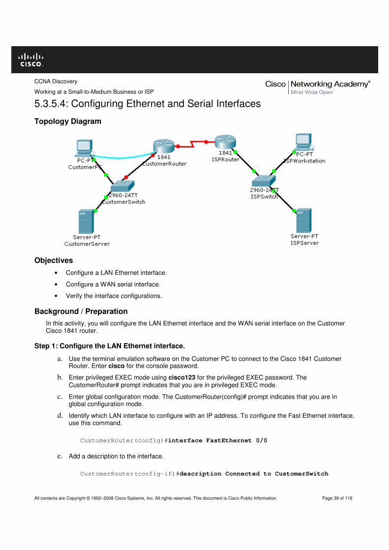
5.3.5.4: Configuring Ethernet and Serial Interfaces
Topology Diagram
Objectives
• Configure a LAN Ethernet interface.
• Configure a WAN serial interface.
• Verify the interface configurations.
Background / Preparation
In this activity, you will configure the LAN Ethernet interface and the WAN serial interface on the Customer Cisco 1841 router.
Step 1: Configure the LAN Ethernet interface.
a. Use the terminal emulation software on the Customer PC to connect to the Cisco 1841 Customer Router. Enter cisco for the console password.
b. Enter privileged EXEC mode using cisco123 for the privileged EXEC password. The CustomerRouter# prompt indicates that you are in privileged EXEC mode.
c. Enter global configuration mode. The CustomerRouter(config)# prompt indicates that you are in global configuration mode.
d. Identify which LAN interface to configure with an IP address. To configure the Fast Ethernet interface, use this command.
CustomerRouter(config)#interface FastEthernet 0/0
e. Add a description to the interface.
CustomerRouter(config-if)#description Connected to CustomerSwitch

CCNA Discovery
Working at a Small-to-Medium Business or ISP
All contents are Copyright © 1992–2008 Cisco Systems, Inc. All rights reserved. This document is Cisco Public Information. Page 40 of 116
f. Specify the IP address and subnet mask for the interface.
CustomerRouter(config-if)#ip address 192.168.1.1 255.255.255.0
g. Ensure that the interface is enabled.
CustomerRouter(config-if)#no shutdown
h. Exit interface configuration mode.
CustomerRouter(config-if)#end
Step 2: Verify the LAN interface configuration.
Use the show ip route command to verify your configuration. This is a partial example of the output.
CustomerRouter#show ip route
<output omitted>
Gateway of last resort is not set
C 192.168.1.0/24 is directly connected, FastEthernet0/0
Step 3: Configure the WAN serial interface.
Refer to the diagram in the Packet Tracer workspace area and the commands used in Step 1 to configure the WAN serial interface on Customer Router.
Tip: Remember the Cisco IOS CLI Help commands to configure the interface.
a. Enter global configuration mode.
b. Identify the serial interface to configure.
c. Describe the interface. (Connected to ISP)
d. Specify the interface IP address and subnet mask. (209.165.200.225 255.255.255.224)
e. Ensure that the interface is enabled.
f. End interface configuration mode.
Step 4: Verify the interface configurations.
Use the show run command to verify your configuration. This is a partial example of the output.
CustomerRouter#show run
...
!
interface FastEthernet0/0
description Connected to CustomerSwitch
CCNA Discovery
Working at a Small-to-Medium Business or ISP
All contents are Copyright © 1992–2008 Cisco Systems, Inc. All rights reserved. This document is Cisco Public Information. Page 41 of 116
ip address 192.168.1.1 255.255.255.0
duplex auto
speed auto
!
interface FastEthernet0/1
no ip address
duplex auto
speed auto
shutdown
!
interface Serial0/1/0
description Connected to ISP
ip address 209.165.200.225 255.255.255.224
!
Use the ping command to verify connectivity to the WAN interface on the ISP router. This is a partial example of the output.
CustomerRouter#ping 209.165.200.226
Type escape sequence to abort.
Sending 5, 100-byte ICMP Echos to 209.165.200.226, timeout is 2
seconds:
!!!!!
Success rate is 100 percent (5/5), round-trip min/avg/max = 35/37/47 ms
Use the ping command to verify connectivity to the customer switch. This is a partial example of the output.
CustomerRouter#ping 192.168.1.1
Type escape sequence to abort.
Sending 5, 100-byte ICMP Echos to 192.168.1.1, timeout is 2 seconds:
!!!!!
Success rate is 100 percent (5/5), round-trip min/avg/max = 0/5/12 ms
Step 5: Save the configuration.
a. In privileged EXEC mode, save the running configuration to the startup configuration.
CustomerRouter#copy run start
b. Click the Check Results button at the bottom of this instruction window to check your work.
Reflection
a. When you ping the LAN IP address of the ISP router, what happens and why?
b. Which of the following Cisco ISO CLI modes do you need to be in to configure the description of an interface?

CCNA Discovery
Working at a Small-to-Medium Business or ISP
All contents are Copyright © 1992–2008 Cisco Systems, Inc. All rights reserved. This document is Cisco Public Information. Page 42 of 116
• CustomerRouter#
• CustomerRouter>
• CustomerRouter(config)#
• CustomerRouter(config-if)#
c. After completing Step 4, what would happen if you rebooted the router before completing Step 5?
CCNA Discovery
Working at a Small-to-Medium Business or ISP
All contents are Copyright © 1992–2008 Cisco Systems, Inc. All rights reserved. This document is Cisco Public Information. Page 43 of 116
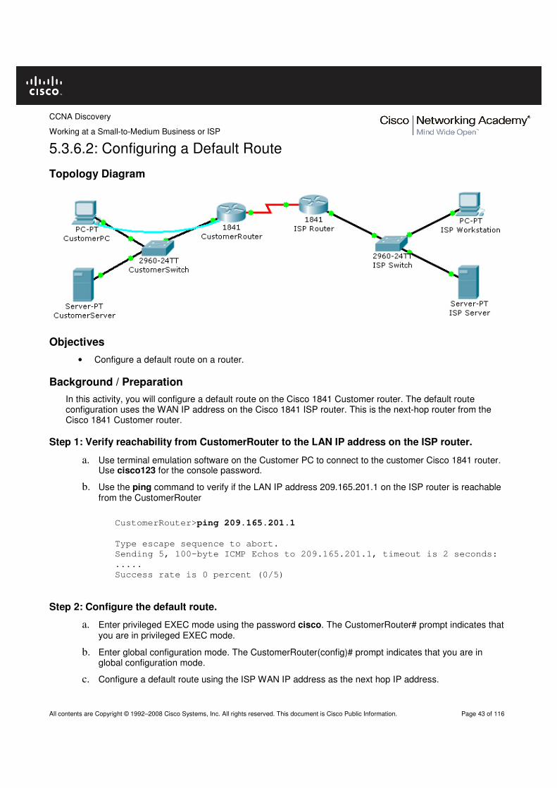
5.3.6.2: Configuring a Default Route
Topology Diagram
Objectives
• Configure a default route on a router.
Background / Preparation
In this activity, you will configure a default route on the Cisco 1841 Customer router. The default route configuration uses the WAN IP address on the Cisco 1841 ISP router. This is the next-hop router from the Cisco 1841 Customer router.
Step 1: Verify reachability from CustomerRouter to the LAN IP address on the ISP router.
a. Use terminal emulation software on the Customer PC to connect to the customer Cisco 1841 router. Use cisco123 for the console password.
b. Use the ping command to verify if the LAN IP address 209.165.201.1 on the ISP router is reachable from the CustomerRouter
CustomerRouter>ping 209.165.201.1
Type escape sequence to abort.
Sending 5, 100-byte ICMP Echos to 209.165.201.1, timeout is 2 seconds:
.....
Success rate is 0 percent (0/5)
Step 2: Configure the default route.
a. Enter privileged EXEC mode using the password cisco. The CustomerRouter# prompt indicates that you are in privileged EXEC mode.
b. Enter global configuration mode. The CustomerRouter(config)# prompt indicates that you are in global configuration mode.
c. Configure a default route using the ISP WAN IP address as the next hop IP address.

CCNA Discovery
Working at a Small-to-Medium Business or ISP
All contents are Copyright © 1992–2008 Cisco Systems, Inc. All rights reserved. This document is Cisco Public Information. Page 44 of 116
CustomerRouter(config)#ip route 0.0.0.0 0.0.0.0 209.165.200.226
CustomerRouter(config)#end
Step 3: Verify the default route configuration.
a. Use the show ip route command to verify the configuration of the default route. This is a partial example of the output.
CustomerRouter#show ip route
Codes: C - connected, S - static,...
Gateway of last resort is 209.165.200.226 to network 0.0.0.0
C 192.168.1.0/24 is directly connected, FastEthernet0/0
209.165.200.0/27 is subnetted, 1 subnets
C 209.165.200.224 is directly connected, Serial0/1/0
S* 0.0.0.0/0 [1/0] via 209.165.200.226
b. Use the ping command to verify connectivity to the LAN IP address on the ISP router
CustomerRouter#ping 209.165.201.1
Type escape sequence to abort.
Sending 5, 100-byte ICMP Echos to 209.165.201.1, timeout is 2 seconds:
!!!!!
Success rate is 100 percent (5/5), round-trip min/avg/max = 22/25/34 ms
Step 4: Save the configuration.
a. From privileged EXEC mode, save the running configuration to the startup configuration.
CustomerRouter#copy run start
b. Click the Check Results button at the bottom of this instruction window to check your work.
Reflection
You can now access the entire ISP network. Write down some issues and considerations to discuss with your classmates about this configuration. Here are two questions to begin with:
• Is this type of access to the ISP LAN likely to happen in the real world?
• Why has the student activity been configured to allow this type of access?

CCNA Discovery
Working at a Small-to-Medium Business or ISP
All contents are Copyright © 1992–2008 Cisco Systems, Inc. All rights reserved. This document is Cisco Public Information. Page 45 of 116
5.3.7.2: Configuring a Cisco Router as a DHCP Server
Topology Diagram
Objectives
• Configure the customer Cisco 1841 ISR as a DHCP server.
Background / Preparation
In this activity, you will continue to configure the Cisco 1841 ISR router for the customer network by configuring the DHCP service. The customer has several workstations that need to be automatically configured with IP addresses on the local subnet and appropriate DHCP options to allow access to the Internet.
The DHCP pool will use the 192.168.1.0/24 network but the first 49 addresses are excluded. The default gateway and DNS server also need to be configured as 192.168.1.1 and 192.168.1.10.
For this activity, both the user and privileged EXEC passwords are cisco.
Note: Packet Tracer does not currently support the domain name and lease period options. These options are not used in this activity.
Step 1: Configure the DHCP service.
a. From the customer workstation, use a console cable and terminal emulation software to connect to the console of the customer Cisco1841 ISR.
b. Log in to the console of the Cisco 1841 ISR and enter global configuration mode.
c. Before creating a DHCP pool, configure the addresses that are excluded. The range is from 192.168.1.1 to 192.168.1.49.
CustomerRouter(config)#ip dhcp excluded-address 192.168.1.1
192.168.1.49
d. Create a DHCP pool called pool1.
CCNA Discovery
Working at a Small-to-Medium Business or ISP
All contents are Copyright © 1992–2008 Cisco Systems, Inc. All rights reserved. This document is Cisco Public Information. Page 46 of 116
CustomerRouter(config)#ip dhcp pool pool1
e. Define the network address range for the DHCP pool.
CustomerRouter(dhcp-config)#network 192.168.1.0 255.255.255.0
f. Define the DNS server as 192.168.1.10.
CustomerRouter(dhcp-config)#dns-server 192.168.1.10
g. Define the default gateway as 192.168.1.1.
CustomerRouter(dhcp-config)#default-router 192.168.1.1
h. Add an exclusion range of 192.168.1.1 to 192.168.1.49 to the DHCP pool.
CustomerRouter(dhcp-config)#exit
CustomerRouter(config)#ip dhcp excluded-address 192.168.1.1
192.168.1.49
i. Exit the terminal.
Step 2: Verify the DHCP configuration.
a. From the customer workstation, open the Command Prompt window.
b. Type ipconfig /release to release the current IP address.
c. Type ipconfig /renew to request a new IP address on the local network.
d. Verify that the IP address has been correctly assigned by pinging the LAN IP address of the Cisco 1841 ISR.
e. Click the Check Results button at the bottom of this instruction window to check your work.
Reflection
a. What is the purpose of DHCP on the customer network?
b. What IP address is assigned to the workstation after its IP address is renewed?
c. What other DHCP options can be defined on the Cisco 1841 ISR router that are not configured in this activity?
CCNA Discovery
Working at a Small-to-Medium Business or ISP
All contents are Copyright © 1992–2008 Cisco Systems, Inc. All rights reserved. This document is Cisco Public Information. Page 47 of 116
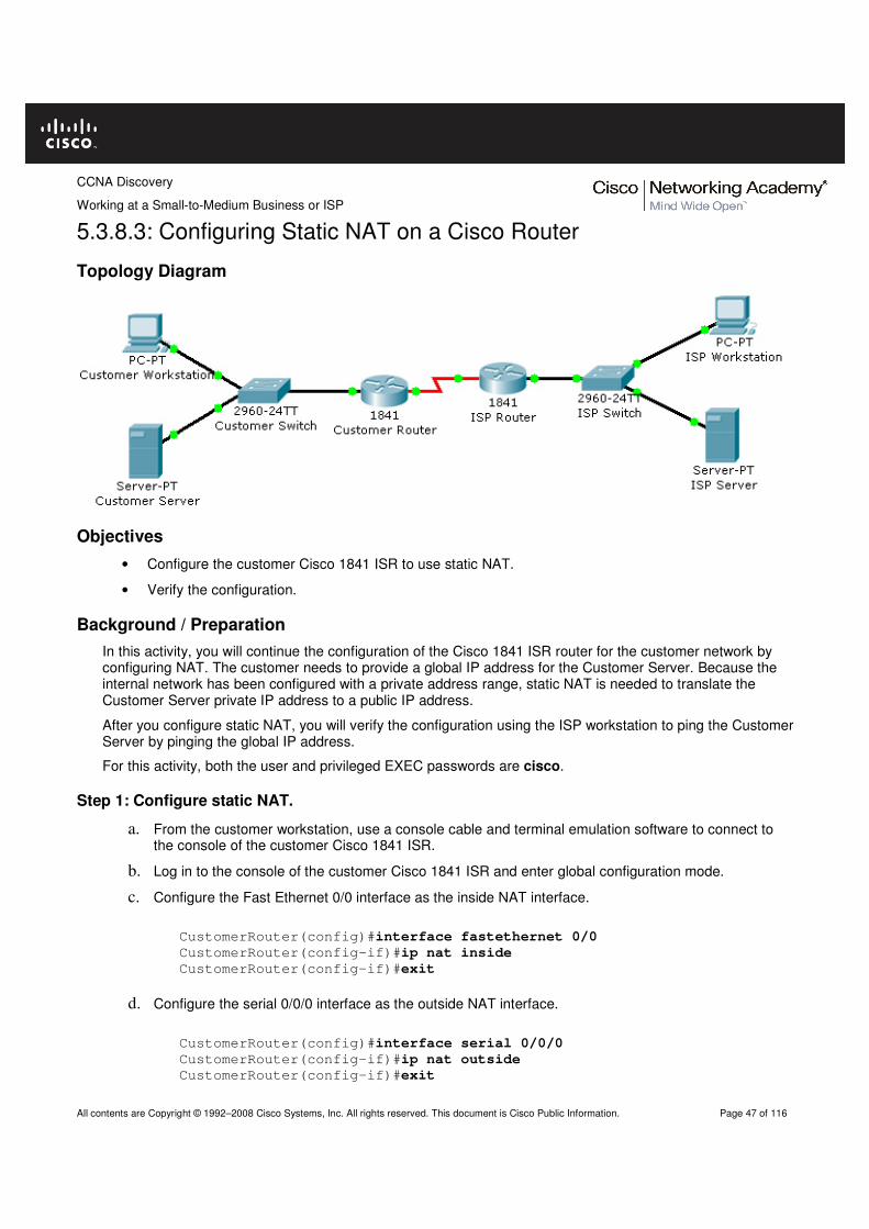
5.3.8.3: Configuring Static NAT on a Cisco Router
Topology Diagram
Objectives
• Configure the customer Cisco 1841 ISR to use static NAT.
• Verify the configuration.
Background / Preparation
In this activity, you will continue the configuration of the Cisco 1841 ISR router for the customer network by configuring NAT. The customer needs to provide a global IP address for the Customer Server. Because the internal network has been configured with a private address range, static NAT is needed to translate the Customer Server private IP address to a public IP address.
After you configure static NAT, you will verify the configuration using the ISP workstation to ping the Customer Server by pinging the global IP address.
For this activity, both the user and privileged EXEC passwords are cisco.
Step 1: Configure static NAT.
a. From the customer workstation, use a console cable and terminal emulation software to connect to the console of the customer Cisco 1841 ISR.
b. Log in to the console of the customer Cisco 1841 ISR and enter global configuration mode.
c. Configure the Fast Ethernet 0/0 interface as the inside NAT interface.
CustomerRouter(config)#interface fastethernet 0/0
CustomerRouter(config-if)#ip nat inside
CustomerRouter(config-if)#exit
d. Configure the serial 0/0/0 interface as the outside NAT interface.
CustomerRouter(config)#interface serial 0/0/0
CustomerRouter(config-if)#ip nat outside
CustomerRouter(config-if)#exit
CCNA Discovery
Working at a Small-to-Medium Business or ISP
All contents are Copyright © 1992–2008 Cisco Systems, Inc. All rights reserved. This document is Cisco Public Information. Page 48 of 116
e. Configure the static NAT mapping that maps the internal 192.168.1.10 address to the 209.165.200.227 external address.
CustomerRouter(config)#ip nat inside source static 192.168.1.10
209.165.200.227
CustomerRouter(config)#exit
f. Close the terminal emulation software on the customer workstation.
Step 2: Verify the static NAT configuration.
a. From the ISP workstation, open the Command Prompt window.
b. Type ping 209.165.200.227 to see if the ISP workstation connects to the Customer Server.
c. Click the Check Results button at the bottom of this instruction window to check your work.
Reflection
a. What is the purpose of static NAT?
b. What command is used to designate the inside interface for static NAT?
c. What IP address does the server respond to when the customer workstation pings the customer DNS server?
CCNA Discovery
Working at a Small-to-Medium Business or ISP
All contents are Copyright © 1992–2008 Cisco Systems, Inc. All rights reserved. This document is Cisco Public Information. Page 49 of 116
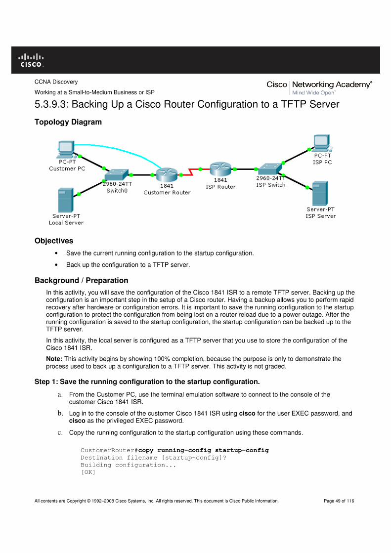
5.3.9.3: Backing Up a Cisco Router Configuration to a TFTP Server
Topology Diagram
Objectives
• Save the current running configuration to the startup configuration.
• Back up the configuration to a TFTP server.
Background / Preparation
In this activity, you will save the configuration of the Cisco 1841 ISR to a remote TFTP server. Backing up the configuration is an important step in the setup of a Cisco router. Having a backup allows you to perform rapid recovery after hardware or configuration errors. It is important to save the running configuration to the startup configuration to protect the configuration from being lost on a router reload due to a power outage. After the running configuration is saved to the startup configuration, the startup configuration can be backed up to the TFTP server.
In this activity, the local server is configured as a TFTP server that you use to store the configuration of the Cisco 1841 ISR.
Note: This activity begins by showing 100% completion, because the purpose is only to demonstrate the process used to back up a configuration to a TFTP server. This activity is not graded.
Step 1: Save the running configuration to the startup configuration.
a. From the Customer PC, use the terminal emulation software to connect to the console of the customer Cisco 1841 ISR.
b. Log in to the console of the customer Cisco 1841 ISR using cisco for the user EXEC password, and cisco as the privileged EXEC password.
c. Copy the running configuration to the startup configuration using these commands.
CustomerRouter#copy running-config startup-config
Destination filename [startup-config]?
Building configuration...
[OK]
CCNA Discovery
Working at a Small-to-Medium Business or ISP
All contents are Copyright © 1992–2008 Cisco Systems, Inc. All rights reserved. This document is Cisco Public Information. Page 50 of 116
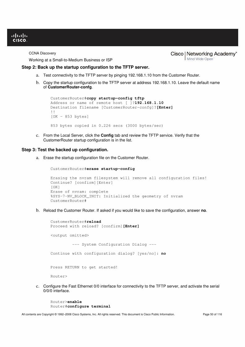
Step 2: Back up the startup configuration to the TFTP server.
a. Test connectivity to the TFTP server by pinging 192.168.1.10 from the Customer Router.
b. Copy the startup configuration to the TFTP server at address 192.168.1.10. Leave the default name of CustomerRouter-confg.
CustomerRouter#copy startup-config tftp
Address or name of remote host [ ]?192.168.1.10
Destination filename [CustomerRouter-confg]?[Enter]
!!
[OK - 853 bytes]
853 bytes copied in 0.226 secs (3000 bytes/sec)
c. From the Local Server, click the Config tab and review the TFTP service. Verify that the CustomerRouter startup configuration is in the list.
Step 3: Test the backed up configuration.
a. Erase the startup configuration file on the Customer Router.
CustomerRouter#erase startup-config
Erasing the nvram filesystem will remove all configuration files!
Continue? [confirm][Enter]
[OK]
Erase of nvram: complete
%SYS-7-NV_BLOCK_INIT: Initialized the geometry of nvram
CustomerRouter#
b. Reload the Customer Router. If asked if you would like to save the configuration, answer no.
CustomerRouter#reload
Proceed with reload? [confirm][Enter]
<output omitted>
--- System Configuration Dialog ---
Continue with configuration dialog? [yes/no]: no
Press RETURN to get started!
Router>
c. Configure the Fast Ethernet 0/0 interface for connectivity to the TFTP server, and activate the serial 0/0/0 interface.
Router>enable
Router#configure terminal

CCNA Discovery
Working at a Small-to-Medium Business or ISP
All contents are Copyright © 1992–2008 Cisco Systems, Inc. All rights reserved. This document is Cisco Public Information. Page 51 of 116
Enter configuration commands, one per line. End with CNTL/Z.
Router(config)#interface fa0/0
Router(config-if)#ip address 192.168.1.1 255.255.255.0
Router(config-if)#no shutdown
Router(config-if)#interface s0/0/0
Router(config-if)#no shutdown
d. Wait for the amber link light on Switch0 to turn green and then ping the TFTP server at 192.168.1.10 to test connectivity.
Router(config-if)#end
%SYS-5-CONFIG_I: Configured from console by console
Router#ping 192.168.1.10
Type escape sequence to abort.
Sending 5, 100-byte ICMP Echos to 192.168.1.10, timeout is 2 seconds:
.!!!!
Success rate is 80 percent (4/5), round-trip min/avg/max = 68/85/105 ms
e. Copy the startup configuration file stored on the TFTP server to the running configuration for Customer Router.
Router#copy tftp running-config
Address or name of remote host []? 192.168.1.10
Source filename []? CustomerRouter-confg
Destination filename [running-config]?
Accessing tftp://192.168.1.10/CustomerRouter-confg...
Loading CustomerRouter-confg from 192.168.1.10: !
[OK - 853 bytes]
853 bytes copied in 0.08 secs (10662 bytes/sec)
CustomerRouter#
f. Copy the restored running configuration to NVRAM.
CustomerRouter#copy running-config startup-config
Destination filename [startup-config]?
Building configuration...
[OK]
CustomerRouter#
g. Test the restored configuration by pinging the ISP server.
CustomerRouter#ping 209.165.201.10
Type escape sequence to abort.
Sending 5, 100-byte ICMP Echos to 209.165.201.10, timeout is 2 seconds:
..!!!
Success rate is 60 percent (3/5), round-trip min/avg/max = 92/120/141
ms

CCNA Discovery
Working at a Small-to-Medium Business or ISP
All contents are Copyright © 1992–2008 Cisco Systems, Inc. All rights reserved. This document is Cisco Public Information. Page 52 of 116
CustomerRouter#
Reflection
a. What are the consequences of reloading a router without saving the running configuration to the startup configuration?
b. How is the backed up startup configuration used to recover from hardware failure in the Cisco 1841 ISR?
c. What command do you use to back up the startup configuration to the TFTP server at IP address 192.168.1.10?
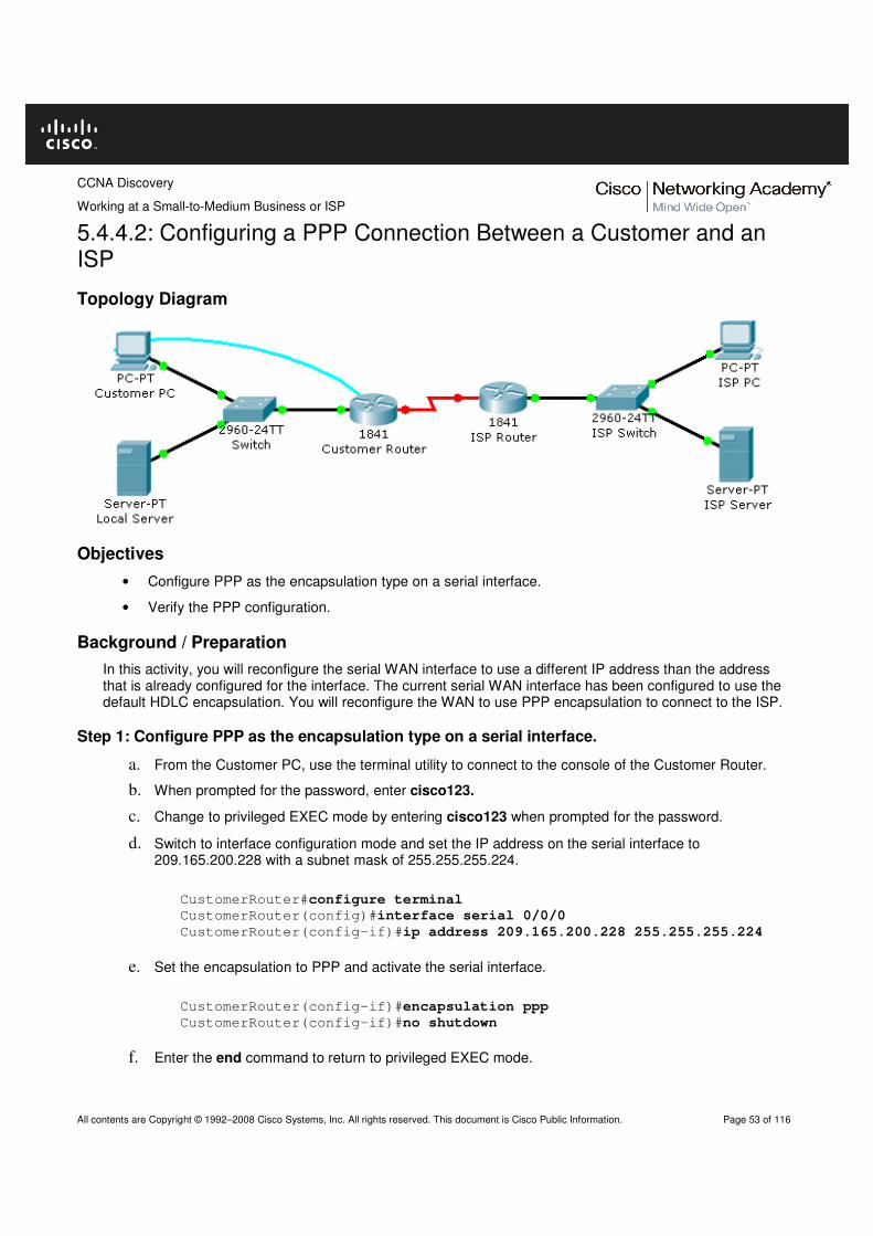
CCNA Discovery
Working at a Small-to-Medium Business or ISP
All contents are Copyright © 1992–2008 Cisco Systems, Inc. All rights reserved. This document is Cisco Public Information. Page 53 of 116
5.4.4.2: Configuring a PPP Connection Between a Customer and an ISP
Topology Diagram
Objectives
• Configure PPP as the encapsulation type on a serial interface.
• Verify the PPP configuration.
Background / Preparation
In this activity, you will reconfigure the serial WAN interface to use a different IP address than the address that is already configured for the interface. The current serial WAN interface has been configured to use the default HDLC encapsulation. You will reconfigure the WAN to use PPP encapsulation to connect to the ISP.
Step 1: Configure PPP as the encapsulation type on a serial interface.
a. From the Customer PC, use the terminal utility to connect to the console of the Customer Router.
b. When prompted for the password, enter cisco123.
c. Change to privileged EXEC mode by entering cisco123 when prompted for the password.
d. Switch to interface configuration mode and set the IP address on the serial interface to 209.165.200.228 with a subnet mask of 255.255.255.224.
CustomerRouter#configure terminal
CustomerRouter(config)#interface serial 0/0/0
CustomerRouter(config-if)#ip address 209.165.200.228 255.255.255.224
e. Set the encapsulation to PPP and activate the serial interface.
CustomerRouter(config-if)#encapsulation ppp
CustomerRouter(config-if)#no shutdown
f. Enter the end command to return to privileged EXEC mode.

CCNA Discovery
Working at a Small-to-Medium Business or ISP
All contents are Copyright © 1992–2008 Cisco Systems, Inc. All rights reserved. This document is Cisco Public Information. Page 54 of 116
CustomerRouter(config-if)#end
CustomerRouter#
Step 2: Verify the PPP configuration.
a. From privileged EXEC mode on the Customer Router, enter the show running-config command and verify that the correct IP address, subnet mask, and encapsulation type are set for the serial 0/0/0 interface.
b. Another command used to verify the IP addressing and encapsulation is show interface.
CustomerRouter#show interface serial 0/0/0
Serial0/0/0 is up, line protocol is up (connected)
Hardware is HD64570
Internet address is
MTU 1500 bytes, BW 128 Kbit, DLY 20000 usec, rely 255/255, load 1/255
, loopback not set, keepalive set (10 sec)
LCP Open
Open: IPCP, CDPCP
<output omitted>
c. Verify that the Customer Router can communicate with the ISP Router over the serial WAN connection. Ping the WAN interface of the ISP Router from the Customer Router.
CustomerRouter#ping 209.165.200.226
d. Click the Check Results button at the bottom of this instruction window to check your work.
Reflection
What are the benefits of using the PPP encapsulation type instead of the default HDLC?
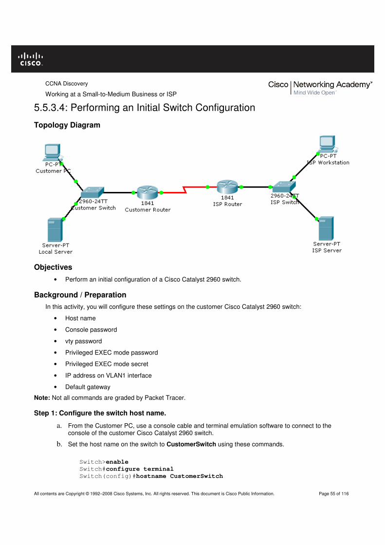
CCNA Discovery
Working at a Small-to-Medium Business or ISP
All contents are Copyright © 1992–2008 Cisco Systems, Inc. All rights reserved. This document is Cisco Public Information. Page 55 of 116
5.5.3.4: Performing an Initial Switch Configuration
Topology Diagram
Objectives
• Perform an initial configuration of a Cisco Catalyst 2960 switch.
Background / Preparation
In this activity, you will configure these settings on the customer Cisco Catalyst 2960 switch:
• Host name
• Console password
• vty password
• Privileged EXEC mode password
• Privileged EXEC mode secret
• IP address on VLAN1 interface
• Default gateway
Note: Not all commands are graded by Packet Tracer.
Step 1: Configure the switch host name.
a. From the Customer PC, use a console cable and terminal emulation software to connect to the console of the customer Cisco Catalyst 2960 switch.
b. Set the host name on the switch to CustomerSwitch using these commands.
Switch>enable
Switch#configure terminal
Switch(config)#hostname CustomerSwitch

CCNA Discovery
Working at a Small-to-Medium Business or ISP
All contents are Copyright © 1992–2008 Cisco Systems, Inc. All rights reserved. This document is Cisco Public Information. Page 56 of 116
Step 2: Configure the privileged mode password and secret.
a. From global configuration mode, configure the password as cisco.
CustomerSwitch(config)#enable password cisco
b. From global configuration mode, configure the secret as cisco123.
CustomerSwitch(config)#enable secret cisco123
Step 3: Configure the console password.
a. From global configuration mode, switch to configuration mode to configure the console line.
CustomerSwitch(config)#line console 0
b. From line configuration mode, set the password to cisco and require the password to be entered at login.
CustomerSwitch(config-line)#password cisco
CustomerSwitch(config-line)#login
CustomerSwitch(config-line)#exit
Step 4: Configure the vty password.
a. From global configuration mode, switch to the configuration mode for the vty lines 0 through 15.
CustomerSwitch(config)#line vty 0 15
b. From line configuration mode, set the password to cisco and require the password to be entered at login.
CustomerSwitch(config-line)#password cisco
CustomerSwitch(config-line)#login
CustomerSwitch(config-line)#exit
Step 5: Configure an IP address on interface VLAN1.
From global configuration mode, switch to interface configuration mode for VLAN1, and assign the IP address 192.168.1.5 with the subnet mask of 255.255.255.0.
CustomerSwitch(config)#interface vlan 1
CustomerSwitch(config-if)#ip address 192.168.1.5 255.255.255.0
CustomerSwitch(config-if)#no shutdown
CustomerSwitch(config-if)#exit
CCNA Discovery
Working at a Small-to-Medium Business or ISP
All contents are Copyright © 1992–2008 Cisco Systems, Inc. All rights reserved. This document is Cisco Public Information. Page 57 of 116
Step 6: Configure the default gateway.
a. From global configuration mode, assign the default gateway to 192.168.1.1.
CustomerSwitch(config)#ip default-gateway 192.168.1.1
b. Click the Check Results button at the bottom of this instruction window to check your work.
Step 7: Verify the configuration.
The Customer Switch should now be able to ping the ISP Server at 209.165.201.10. The first one or two pings may fail while ARP converges.
CustomerSwitch(config)#end
CustomerSwitch#ping 209.165.201.10
Type escape sequence to abort.
Sending 5, 100-byte ICMP Echos to 209.165.201.10, timeout is 2 seconds:
..!!!
Success rate is 60 percent (3/5), round-trip min/avg/max = 181/189/197
ms
CustomerSwitch#
Reflection
a. What is the significance of assigning the IP address to the VLAN1 interface instead of any of the Fast Ethernet interfaces?
b. What command is necessary to enforce password authentication on the console and vty lines?
c. How many gigabit ports are available on the Cisco Catalyst 2960 switch that you used in the activity?
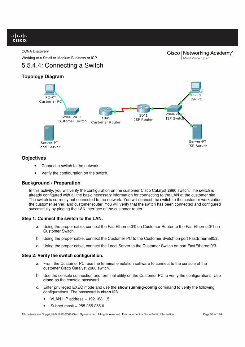
CCNA Discovery
Working at a Small-to-Medium Business or ISP
All contents are Copyright © 1992–2008 Cisco Systems, Inc. All rights reserved. This document is Cisco Public Information. Page 58 of 116
5.5.4.4: Connecting a Switch
Topology Diagram
Objectives
• Connect a switch to the network.
• Verify the configuration on the switch.
Background / Preparation
In this activity, you will verify the configuration on the customer Cisco Catalyst 2960 switch. The switch is already configured with all the basic necessary information for connecting to the LAN at the customer site. The switch is currently not connected to the network. You will connect the switch to the customer workstation, the customer server, and customer router. You will verify that the switch has been connected and configured successfully by pinging the LAN interface of the customer router.
Step 1: Connect the switch to the LAN.
a. Using the proper cable, connect the FastEthernet0/0 on Customer Router to the FastEthernet0/1 on Customer Switch.
b. Using the proper cable, connect the Customer PC to the Customer Switch on port FastEthernet0/2.
c. Using the proper cable, connect the Local Server to the Customer Switch on port FastEthernet0/3.
Step 2: Verify the switch configuration.
a. From the Customer PC, use the terminal emulation software to connect to the console of the customer Cisco Catalyst 2960 switch.
b. Use the console connection and terminal utility on the Customer PC to verify the configurations. Use cisco as the console password.
c. Enter privileged EXEC mode and use the show running-config command to verify the following configurations. The password is cisco123.
• VLAN1 IP address = 192.168.1.5
• Subnet mask = 255.255.255.0

CCNA Discovery
Working at a Small-to-Medium Business or ISP
All contents are Copyright © 1992–2008 Cisco Systems, Inc. All rights reserved. This document is Cisco Public Information. Page 59 of 116
• Password required for console access
• Password required for vty access
• Password enabled for privileged EXEC mode
• Secret enabled for privileged EXEC mode
d. Verify IP connectivity between the Cisco Catalyst 2960 switch and the Cisco 1841 router by initiating a ping to 192.168.1.1 from the switch CLI.
e. Click the Check Results button at the bottom of this instruction window to check your work.
Reflection
a. What is the significance of the enable secret command compared to the enable password?
b. If you want to remove the requirement to enter a password to access the console, what commands do you issue from your starting point in privileged EXEC mode?

CCNA Discovery
Working at a Small-to-Medium Business or ISP
All contents are Copyright © 1992–2008 Cisco Systems, Inc. All rights reserved. This document is Cisco Public Information. Page 60 of 116
5.5.5.2: Using CDP as a Network Discovery Tool
Topology Diagram
Objectives
• Examine CDP show commands.
• Examine CDP configuration commands.
Background / Preparation
Cisco Discovery Protocol (CDP) is an OSI Layer 2 protocol that operates between Cisco devices, such as routers and switches. CDP messages contain information about the device, such as device ID, platform, connected interface, Cisco IOS software version, and Layer 3 address. Because CDP operates at Layer 2, only directly connected devices exchange information.
Note: This activity begins by showing 100% completion, because the purpose is only to demonstrate how CDP can be used to map a network. This activity is not graded.
Step 1: View CDP configuration settings.
a. On router R1, issue the show cdp command. The output shows timer and version information.
b. Issue the show cdp ? command to see a list of the other CDP show commands.
c. Issue the show cdp interface command. The output shows timer information for all the interfaces on the router. You can specify a particular interface to show timer information for that interface only.
CCNA Discovery
Working at a Small-to-Medium Business or ISP
All contents are Copyright © 1992–2008 Cisco Systems, Inc. All rights reserved. This document is Cisco Public Information. Page 61 of 116
Step 2: View CDP neighbor information.
a. A router builds a table of information about neighboring devices from CDP messages received from those devices. On router R1, issue the show cdp neighbors command.
Packet Tracer operates in real time, like actual network equipment. If you do not see two entries in the output of the command, wait a couple of minutes and reissue the command until you do.
b. Examine the output. A single line of information is displayed for each device. Information is displayed for switch S1 and router R2, which are directly connected, but not for router R3, which is not directly connected.
c. Issue the show cdp entry R2 command. Examine the output. More detailed information about router R2 is displayed, including the IP address used to reach the router.
d. Issue the show cdp entry * command. Examine the output. Detailed information about all directly connected devices is displayed.
e. Issue the show cdp neighbors detail command. Examine the output. The same information as the show cdp entry * command is displayed.
Step 3: Disable and enable CDP globally on a router.
a. On router R2, issue the show cdp neighbors command. The output shows information about the three directly connected devices.
b. Enter global configuration mode. Issue the no cdp run command to disable CDP on the router. Exit configuration mode and issue the show cdp neighbors command. The output shows that CDP is not enabled.
c. On router R1, issue the show cdp neighbors command. If the output shows an entry for R2, wait the number of seconds shown for the Holdtime entry on R2, and then reissue the command.
The entry for R2 will no longer be shown because no CDP messages were received before the Holdtime expired.
d. On router R2, enter global configuration mode. Issue the cdp run command to enable CDP on the router.
Step 4: Disable and enable CDP on an interface.
a. You may not want to send CDP information to Cisco devices on an untrusted network. It is possible to disable CDP on a specific interface.
b. On router R2, enter global configuration mode. Enter interface configuration mode for interface Serial0/0/1, and issue the no cdp enable command to disable CDP on the interface. Exit configuration mode.
c. Issue the show cdp neighbors command on both router R2 and router R3 until the entry for R3 times out of the CDP table on R2, and the entry for R2 times out of the CDP table on R3.
d. On router R2, enter global configuration mode. Enter interface configuration mode for interface Serial0/0/1, and issue the cdp enable command to enable CDP on the interface.
Reflection
You now have a basic understanding of CDP. Write down some issues and considerations to discuss with your classmates about CDP. For a start, here are two questions:

CCNA Discovery
Working at a Small-to-Medium Business or ISP
All contents are Copyright © 1992–2008 Cisco Systems, Inc. All rights reserved. This document is Cisco Public Information. Page 62 of 116
• How could CDP be used to troubleshoot network connectivity issues?
• Is it likely that an ISP would have CDP configured on its gateway router?
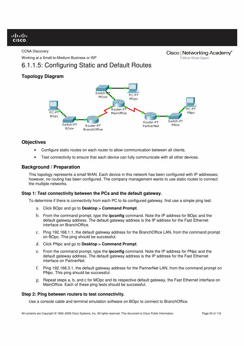
CCNA Discovery
Working at a Small-to-Medium Business or ISP
All contents are Copyright © 1992–2008 Cisco Systems, Inc. All rights reserved. This document is Cisco Public Information. Page 63 of 116
6.1.1.5: Configuring Static and Default Routes
Topology Diagram
Objectives
• Configure static routes on each router to allow communication between all clients.
• Test connectivity to ensure that each device can fully communicate with all other devices.
Background / Preparation
This topology represents a small WAN. Each device in this network has been configured with IP addresses; however, no routing has been configured. The company management wants to use static routes to connect the multiple networks.
Step 1: Test connectivity between the PCs and the default gateway.
To determine if there is connectivity from each PC to its configured gateway, first use a simple ping test.
a. Click BOpc and go to Desktop > Command Prompt.
b. From the command prompt, type the ipconfig command. Note the IP address for BOpc and the default gateway address. The default gateway address is the IP address for the Fast Ethernet interface on BranchOffice.
c. Ping 192.168.1.1, the default gateway address for the BranchOffice LAN, from the command prompt on BOpc. This ping should be successful.
d. Click PNpc and go to Desktop > Command Prompt.
e. From the command prompt, type the ipconfig command. Note the IP address for PNpc and the default gateway address. The default gateway address is the IP address for the Fast Ethernet interface on PartnerNet.
f. Ping 192.168.3.1, the default gateway address for the PartnerNet LAN, from the command prompt on PNpc. This ping should be successful.
g. Repeat steps a, b, and c for MOpc and its respective default gateway, the Fast Ethernet interface on MainOffice. Each of these ping tests should be successful.
Step 2: Ping between routers to test connectivity.
Use a console cable and terminal emulation software on BOpc to connect to BranchOffice.

CCNA Discovery
Working at a Small-to-Medium Business or ISP
All contents are Copyright © 1992–2008 Cisco Systems, Inc. All rights reserved. This document is Cisco Public Information. Page 64 of 116
a. Test connectivity with MainOffice by pinging 10.10.10.1, the IP address of the directly connected serial 3/0 interface. This ping should succeed.
b. Test connectivity with MainOffice by pinging 10.10.10.5, the IP address of the serial 2/0 interface. This ping should fail.
c. Issue the show ip route command from the terminal window of BOpc. Note that only directly connected routes are shown in the BranchOffice routing table. The ping to 10.10.10.5 failed because the BranchOffice router has no routing table entry for 10.10.10.5.
d. Repeat steps a through d on the other two PCs. The pings to directly connected networks will succeed. However, pings to remote networks will fail.
e. What steps must be taken to reach all the networks from any PC in the activity?
Step 3: Viewing the routing tables.
You can view routing tables in Packet Tracer using the Inspect tool. The Inspect tool is in the Common Tools bar to the right of the topology. The Inspect tool is the icon that appears as a magnifying glass.
a. In the Common Tools bar, click on the Inspect tool.
b. Click the MainOffice router and choose Routing Table.
c. Click the BranchOffice router and choose Routing Table.
d. Click the PartnerNet router and choose Routing Table.
e. Move the routing table windows around so that you can see all three at once.
f. What networks do each of the routers already know about?
g. Does each router know how to route to all networks in the topology? After comparing the routing tables, close the window for each routing table by clicking the x in the upper right corner of each window.
Step 4: Configure default routes on the BranchOffice and PartnerNet routers.
To configure static routes for each router, first determine which routes need to be added for each device. For the BranchOffice and the PartnerNet routers, a single default route allows these devices to route traffic for all networks not directly connected. To configure a default route, you must identify the IP address of the next hop router, which in this case is the MainOffice router.
a. From the Common toolbar, click the Select tool.
b. Move the cursor over the red serial link between the BranchOffice router and the MainOffice router. Notice that the interface of the next hop is S3/0.
c. Move the cursor over the MainOffice router and note that the IP address for Serial 3/0 is 10.10.10.1.
d. Move the cursor over the red serial link between the PartnerNet router and the MainOffice router. Notice that the interface of the next hop is S2/0.
e. Move the cursor over the MainOffice router and note that the IP address for Serial 2/0 is 10.10.10.5.
f. Configure the static routes on both the BranchOffice and PartnerNet routers using the CLI. Click the BranchOffice router, and click the CLI tab.

CCNA Discovery
Working at a Small-to-Medium Business or ISP
All contents are Copyright © 1992–2008 Cisco Systems, Inc. All rights reserved. This document is Cisco Public Information. Page 65 of 116
g. At the BranchOffice> prompt, type enable to enter privileged EXEC mode.
h. At the BranchOffice# prompt, type configure terminal.
i. The syntax for a default route is ip route 0.0.0.0 0.0.0.0 next_hop_ip_address. Type ip route 0.0.0.0 0.0.0.0 10.10.10.1.
j. Type end to get back to the BranchOffice# prompt.
k. Type copy run start to save the configuration change.
l. Repeat steps f through k on the PartnerNet router, using 10.10.10.5 as the next hop IP address.
Step 5: Configure static routes at Main Office.
The configuration of static routes at the Main Office is a bit more complex because the MainOffice router is responsible for routing traffic to and from the Branch Office and PartnerNet LAN segments.
The MainOffice router knows only about routes to the 10.10.10.0/30, 10.10.10.4/30, and 192.168.2.0/24 networks because they are directly connected. Static routes to the 192.168.1.0/24 and 192.168.3.0/24 networks need to be added so that the MainOffice router can route traffic between the networks behind the BranchOffice and PartnerNet routers.
a. Click the MainOffice router, and then click the CLI tab.
b. At the MainOffice> prompt, type enable to enter privileged EXEC mode.
c. At the MainOffice# prompt, type configure terminal.
d. The syntax for a static route is ip route network subnet_mask next_hop_ip_address:
ip route 192.168.1.0 255.255.255.0 10.10.10.2
ip route 192.168.3.0 255.255.255.0 10.10.10.6
e. Type end to return to the MainOffice# prompt.
f. Type copy run start to save the configuration change.
g. Repeat steps a through e from Step 3. View the routing tables and notice the difference in the routing tables. The routing table for each router should have an “S” for each static route.
Step 6: Test connectivity.
Now that each router in the topology has static routes configured, all hosts should have connectivity to all other hosts. Use ping to verify connectivity.
a. Click BOpc and click the Desktop tab.
b. Choose the Command prompt option.
c. Type ping 192.168.3.2. The ping should be successful, verifying that the static routes are configured properly.
d. Type ping 192.168.2.2. Notice that the result is successful even though you did not specifically add the 192.168.2.0 network as a static route into any of the routers. Because a default route was used on the BranchOffice and PartnerNet routers, a route for the 192.168.2.0 network was not needed. The default route sends all traffic destined off network to the MainOffice router. The 192.168.2.0 network is directly connected to the MainOffice router; therefore, no additional routes needed to be added to the routing table

CCNA Discovery
Working at a Small-to-Medium Business or ISP
All contents are Copyright © 1992–2008 Cisco Systems, Inc. All rights reserved. This document is Cisco Public Information. Page 66 of 116
e. Click the Check Results button at the bottom of this instruction window to check your work.

CCNA Discovery
Working at a Small-to-Medium Business or ISP
All contents are Copyright © 1992–2008 Cisco Systems, Inc. All rights reserved. This document is Cisco Public Information. Page 67 of 116
6.1.5.3: Configuring RIP
Topology Diagram
Objectives
• Configure routers using basic interface configuration commands.
• Enable RIP.
• Verify the RIP configuration.
Background / Preparation
A simple routed network has been set up to assist in reviewing RIP routing behavior. In this activity, you will configure RIP across the network and set up end devices to communicate on the network.
Step 1: Configure the SVC01 router and enable RIP.
a. From the CLI, configure interface Fast Ethernet 0/0 using the IP address 10.0.0.254 /8.
b. Configure interface serial 0/0/0 using the first usable IP address in network 192.168.1.0 /24 to connect to the RTR01 router. Set the clock rate at 64000.
c. Configure interface serial 0/0/1 using the first usable IP address in network 192.168.2.0 /24 with a clock rate of 64000.
d. Using the no shutdown command, enable the configured interfaces.
e. Configure RIP to advertise the networks for the configured interfaces.
f. Configure the end devices.

CCNA Discovery
Working at a Small-to-Medium Business or ISP
All contents are Copyright © 1992–2008 Cisco Systems, Inc. All rights reserved. This document is Cisco Public Information. Page 68 of 116
• Server0 uses the first usable IP address in network 10.0.0.0 /8. Specify the appropriate default gateway and subnet mask.
• Printer0 uses the second usable IP address in network 10.0.0.0 /8. Specify the appropriate default gateway and subnet mask.
Step 2: Configure the RTR01 router and enable RIP.
a. Configure interface Fast Ethernet 0/0 using the first usable IP address in network 192.168.0.0 /24 to connect to the RTR02 router.
b. Configure interface serial 0/0/0 using the second usable IP address in network 192.168.1.0 /24 to connect to the SVC01 router.
c. Configure interface Fast Ethernet 0/1 using the IP address 172.16.254.254 /16.
d. Using the no shutdown command, enable the configured interfaces.
e. Configure RIP to advertise the networks for the configured interfaces.
f. Configure the end devices.
• PC0 uses the first usable IP addresses in network 172.16.0.0 /16.
• PC1 uses the second usable IP address in network 172.16.0.0 /16.
• Specify the appropriate default gateway and subnet mask on each PC.
Step 3: Configure the RTR02 router and enable RIP.
a. Configure interface Fast Ethernet 0/0 using the second usable IP address in network 192.168.0.0 /24 to connect to the RTR01 router.
b. Configure interface serial 0/0/0 using the second usable IP address in network 192.168.2.0 /24 to connect to the SVC01 router.
c. Configure interface Fast Ethernet 0/1 using the IP address 172.17.254.254 /16.
d. Using the no shutdown command, enable the configured interfaces.
e. Configure RIP to advertise the networks for the configured interfaces.
f. Configure the end devices.
• PC2 uses the first usable IP addresses in network 172.17.0.0 /16.
• PC3 uses the second usable IP address in network 172.17.0.0 /16.
• Specify the appropriate default gateway and subnet mask on each PC.
Step 4: Verify the RIP configuration on each router.
a. At the command prompt for each router, issue the commands show ip protocols and show ip route to verify RIP routing is fully converged. The show ip protocols command displays the networks the router is advertising and the addresses of other RIP routing neighbors. The show ip route command output displays all routes know to the local router including the RIP routes which are indicated by an “R”.
b. Every device should now be able to successfully ping any other device in this activity.
c. Click the Check Results button at the bottom of this instruction window to check your work.

CCNA Discovery
Working at a Small-to-Medium Business or ISP
All contents are Copyright © 1992–2008 Cisco Systems, Inc. All rights reserved. This document is Cisco Public Information. Page 69 of 116
8.2.2.3: Planning Network-based Firewalls
Topology Diagram
Objectives
• Place firewalls in appropriate locations to satisfy security requirements.
Background / Preparation
You are a technician who provides network support for a medium-sized business. The business has grown and includes a research and development department working on a new, very confidential project. The livelihood of the project depends on protecting the data used by the research and development team.
Your job is to install firewalls to help protect the network, based on specific requirements. The Packet Tracer topology that you will use includes two preconfigured firewalls. In the two scenarios presented, you will replace the existing routers with the firewalls. The firewalls need to be configured with the appropriate IP address configurations, and the firewalls should be tested to ensure that they are installed and configured correctly.
Scenario 1: Protecting the Network from Hackers
Because the company is concerned about security, you recommend a firewall to protect the network from hackers on the Internet. It is very important that access to the network from the Internet is restricted.
Firewall_1 has been preconfigured with the appropriate rules to provide the security required. You will install it on the network and confirm that it is functioning as expected.

CCNA Discovery
Working at a Small-to-Medium Business or ISP
All contents are Copyright © 1992–2008 Cisco Systems, Inc. All rights reserved. This document is Cisco Public Information. Page 70 of 116
Step 1: Replace Router_A with Firewall_1.
a. Remove Router_A and replace it with Firewall_1.
b. Connect the Fast Ethernet 0/0 interface on Firewall_1 to the Fast Ethernet 0/1 interface on Switch_A. Connect the Fast Ethernet 0/1 interface on Firewall_1 to the Ethernet 6 interface of the ISP cloud. (Use straight-through cables for both connections.)
c. Confirm that the host name of Firewall_1 is Firewall_1.
d. On Firewall_1, configure the WAN IP address and subnet mask for the FastEthernet 0/1 interface as 209.165.200.225 and 255.255.255.224.
e. Configure the LAN IP address and subnet mask for the Fast Ethernet 0/0 interface on Firewall_1 as 192.168.1.1 and 255.255.255.0.
Step 2: Verify the Firewall_1 configuration.
a. Use the show run command to verify your configuration. This is a partial example of the output.
Firewall_1#show run
Building configuration...
hostname Firewall_1
!
interface FastEthernet0/0
ip address 192.168.1.1 255.255.255.0
ip nat inside
duplex auto
speed auto
!
interface FastEthernet0/1
ip address 209.165.200.225 255.255.255.224
ip access-group 100 in
ip nat outside
duplex auto
speed auto
!
interface Vlan1
no ip address
shutdown
!
ip nat inside source list 1 interface FastEthernet0/0 overload
ip classless
ip route 192.168.2.0 255.255.255.0 192.168.1.2
ip route 192.168.3.0 255.255.255.0 192.168.1.3
!
access-list 1 permit 192.168.0.0 0.0.255.255
access-list 100 deny ip any host 209.165.200.225
<output omitted>
!
end
b. From PC_B, ping 209.165.200.225 to verify that the internal computer can access the Internet.

CCNA Discovery
Working at a Small-to-Medium Business or ISP
All contents are Copyright © 1992–2008 Cisco Systems, Inc. All rights reserved. This document is Cisco Public Information. Page 71 of 116
PC>ping 209.165.200.225
Pinging 209.165.200.225 with 32 bytes of data:
Reply from 209.165.200.225: bytes=32 time=107ms TTL=120
Reply from 209.165.200.225: bytes=32 time=98ms TTL=120
Reply from 209.165.200.225: bytes=32 time=104ms TTL=120
Reply from 209.165.200.225: bytes=32 time=95ms TTL=120
Ping statistics for 209.165.200.225:
Packets: Sent = 4, Received = 4, Lost = 0 (0% loss),
Approximate round trip times in milli-seconds:
Minimum = 95ms, Maximum = 107ms, Average = 101ms
c. From privileged EXEC mode on Firewall_1, save the running configuration to the startup configuration using the copy run start command.
Scenario 2: Securing the Research and Development Network
Now that the entire network is secured from traffic originating from the Internet, secure the research and development network, Subnet C, from potential breaches from inside the network. The research and development team needs access to both the server on Subnet B and the Internet to conduct research. Computers on Subnet B should be denied access to the research and development subnet.
Firewall_2 has been preconfigured with the appropriate rules to provide the security required. You will install it on the network and confirm that it is functioning as expected.
Step 1: Replace Router_C with Firewall_2.
a. Remove Router_C and replace it with Firewall_2.
b. Connect the Fast Ethernet 0/1 interface on Firewall_2 to the Fast Ethernet 0/3 interface on Switch_A. Connect the Fast Ethernet 0/0 interface on Firewall_2 to the Fast Ethernet 0/1 interface on Switch_C. (Use straight-through cables for both connections.)
c. Confirm that the host name of Firewall_2 is Firewall_2.
d. On Firewall_2, configure the WAN IP address and subnet mask for the Fast Ethernet 0/1 interface as 192.168.1.3 and 255.255.255.0.
e. Configure the LAN IP address and subnet mask for the Fast Ethernet 0/0 interface of Firewall_2 as 192.168.3.1 and 255.255.255.0.
Step 2: Verify the Firewall_2 configuration.
a. Use the show run command to verify the configuration. This is a partial example of the output.
Firewall_2#show run
Building configuration...
...
!
interface FastEthernet0/0
ip address 192.168.3.1 255.255.255.0

CCNA Discovery
Working at a Small-to-Medium Business or ISP
All contents are Copyright © 1992–2008 Cisco Systems, Inc. All rights reserved. This document is Cisco Public Information. Page 72 of 116
ip nat inside
duplex auto
speed auto
!
interface FastEthernet0/1
ip address 192.168.1.3 255.255.255.0
ip access-group 100 in
ip nat outside
duplex auto
speed auto
!
access-list 1 permit 192.168.3.0 0.0.0.255
access-list 100 permit ip host 192.168.2.10 any
access-list 100 permit ip host 192.168.1.1 any
<output omitted>
!
end
b. From the command prompt on PC_B, use the ping command to verify that the computers on Subnet B cannot access the computers on Subnet C.
PC>ping 192.168.3.10
Pinging 192.168.3.10 with 32 bytes of data:
Request timed out.
Request timed out.
Request timed out.
Request timed out.
Ping statistics for 192.168.3.10:
Packets: Sent = 4, Received = 0, Lost = 4 (100% loss),
c. From the command prompt on PC_C, use the ping command to verify that the computers on Subnet C can access the server on Subnet B.
PC>ping 192.168.2.10
Pinging 192.168.2.10 with 32 bytes of data:
Request timed out.
Reply from 192.168.2.10: bytes=32 time=164ms TTL=120
Reply from 192.168.2.10: bytes=32 time=184ms TTL=120
Reply from 192.168.2.10: bytes=32 time=142ms TTL=120
Ping statistics for 192.168.2.10:
Packets: Sent = 4, Received = 3, Lost = 1 (25% loss),
Approximate round trip times in milli-seconds:
Minimum = 142ms, Maximum = 184ms, Average = 163ms
d. From the command prompt on PC_C, use the ping command to verify that the computers on Subnet C can access the Internet.

CCNA Discovery
Working at a Small-to-Medium Business or ISP
All contents are Copyright © 1992–2008 Cisco Systems, Inc. All rights reserved. This document is Cisco Public Information. Page 73 of 116
PC>ping 209.165.200.225
Pinging 209.165.200.225 with 32 bytes of data:
Reply from 209.165.200.225: bytes=32 time=97ms TTL=120
Reply from 209.165.200.225: bytes=32 time=118ms TTL=120
Reply from 209.165.200.225: bytes=32 time=100ms TTL=120
Reply from 209.165.200.225: bytes=32 time=110ms TTL=120
Ping statistics for 209.165.200.225:
Packets: Sent = 4, Received = 4, Lost = 0 (0% loss),
Approximate round trip times in milli-seconds:
Minimum = 97ms, Maximum = 118ms, Average = 106ms
e. From privileged EXEC mode on Firewall_2, save the running configuration to the startup configuration using the copy run start command.
f. Click the Check Results button at the bottom of this instruction window to check your work.
Reflection
a. Why would you install a firewall on the internal network?
b. How does a router that is configured to use NAT help protect computer systems on the inside of the NAT router?
c. Examine the location of Firewall_1 and Firewall_2 in the completed network topology. Which networks are considered trusted and untrusted for Firewall_1? Which networks are considered trusted and untrusted for Firewall_2?

CCNA Discovery
Working at a Small-to-Medium Business or ISP
All contents are Copyright © 1992–2008 Cisco Systems, Inc. All rights reserved. This document is Cisco Public Information. Page 74 of 116
8.2.4.3: Configuring WEP on a Wireless Router
Topology Diagram
Objectives
• Configure WEP security between a workstation and a Linksys wireless router.
Background / Preparation
You have been asked to return to a business customer and install a new Linksys wireless router for the customer office. The company has some new personnel who will be using wireless computers to save money on adding additional networked connections to the building. The business is concerned about the security of the network because they have financial and highly classified data being transmitted over the network. Your job is to configure the security on the router to protect the data.
In this activity, you will configure WEP security on both a Linksys wireless router and a workstation.
Step 1: Configure the Linksys wireless router to require WEP.
a. Click the Customer Wireless Router icon. Then, click the GUI tab to access the router web management interface.
b. Click the Wireless menu option and change the Network Name (SSID) from Default to CustomerWireless. Leave the other settings with their default options.
c. Click the Save Settings button at the bottom of the Basic Wireless Settings window.
d. Click the Wireless Security submenu under the Wireless menu to display the current wireless security parameters.
e. From the Security Mode drop-down menu, select WEP.
f. In the Key1 text box, type 1a2b3c4d5e. This will be the new WEP pre-shared key to access the wireless network.
g. Click the Save Settings button at the bottom of the Wireless Security window.
CCNA Discovery
Working at a Small-to-Medium Business or ISP
All contents are Copyright © 1992–2008 Cisco Systems, Inc. All rights reserved. This document is Cisco Public Information. Page 75 of 116
Step 2: Configure WEP on the customer wireless workstation.
a. Click the Customer Wireless Workstation.
b. Click the Config tab.
c. Click the Wireless button to display the current wireless configuration settings on the workstation.
d. Change the SSID to CustomerWireless.
e. Change the Security Mode to WEP. Enter 1a2b3c4d5e in the Key text box, and then close the window.
Step 3: Verify the configuration.
After you configure the correct WEP key and SSID on the customer wireless workstation, notice that there is a wireless connection between the workstation and the wireless router.
a. Click the Customer Wireless Workstation.
b. Click the Desktop tab to view the applications that are available.
c. Click on the Command Prompt application to bring up the command prompt.
d. Type ipconfig /all and press Enter to view the current network configuration settings.
e. Type ping 192.168.2.1 to verify connectivity to the LAN interface of the customer wireless router.
f. Close the command prompt window.
g. Open a web browser.
h. In the address bar of the web browser window, type http://192.168.1.10. Press Enter. The Intranet web page that is running on the customer server appears. You have just verified that the customer wireless workstation has connectivity to the rest of the customer network.
i. Click the Check Results button at the bottom of this instruction window to check your work.
Reflection
a. What is the purpose of using WEP on a wireless network?
b. What is the significance of the key that you used to secure WEP?
c. Is WEP the best choice for wireless security?

CCNA Discovery
Working at a Small-to-Medium Business or ISP
All contents are Copyright © 1992–2008 Cisco Systems, Inc. All rights reserved. This document is Cisco Public Information. Page 76 of 116
9.2.4.3: Configuring and Troubleshooting a Switched Network
Topology Diagram
Objectives
• Establish console connection to the switch.
• Configure the host name and VLAN1.
• Use the help feature to configure the clock.
• Configure passwords and console/Telnet access.
• Configure login banners.
• Configure the router.
• Solve duplex and speed mismatch problems.
• Configure port security.
• Secure unused ports.
• Manage the switch configuration file.
Background / Preparation
In this Packet Tracer Skills Integration Challenge activity, you will configure basic switch management, including general maintenance commands, passwords, and port security. This activity provides you an opportunity to review previously acquired skills.

CCNA Discovery
Working at a Small-to-Medium Business or ISP
All contents are Copyright © 1992–2008 Cisco Systems, Inc. All rights reserved. This document is Cisco Public Information. Page 77 of 116
Addressing Table
Device Interface IP Address Subnet Mask
R1 Fa0/0 172.17.99.1 255.255.255.0
S1 Fa0/1 172.17.99.11 255.255.255.0
PC1 NIC 172.17.99.21 255.255.255.0
PC2 NIC 172.17.99.22 255.255.255.0
Server NIC 172.17.99.31 255.255.255.0
Step 1: Establish a console connection to a switch.
For this activity, direct access to the S1 Config and CLI tabs is disabled. You must establish a console session through PC1.
a. Connect a console cable from PC1 to S1.
b. From PC1, open a terminal window and use the default terminal configuration. You should now have access to the CLI for S1.
c. Check results.
Your completion percentage should be 8%. If not, click Check Results to see which required components are not yet completed.
Step 2: Configure the host name and VLAN 1.
a. Configure the switch host name as S1.
b. Configure port Fa0/1. Set the mode on Fast Ethernet 0/1 to access mode.
S1(config)#interface fastethernet 0/1
S1(config-if)#switchport mode access
c. Configure IP connectivity on S1 using VLAN 1.
S1(config)#interface vlan 1
S1(config-if)#ip address 172.17.99.11 255.255.255.0
S1(config-if)#no shutdown
d. Configure the default gateway for S1 and then test connectivity. S1 should be able to ping R1.
e. Check results.
Your completion percentage should be 31%. If not, click Check Results to see which required components are not yet completed. Also, make sure that interface VLAN 1 is active.
Step 3: Configure the current time using Help.
a. Configure the clock to the current time. At the privileged EXEC prompt, enter clock ?.
b. Use Help to discover the steps required to set the current time.
CCNA Discovery
Working at a Small-to-Medium Business or ISP
All contents are Copyright © 1992–2008 Cisco Systems, Inc. All rights reserved. This document is Cisco Public Information. Page 78 of 116
c. Use the show clock command to verify that the clock is now set to the current time. Packet Tracer may not correctly simulate the time you entered.
Packet Tracer does not grade this command, so the completion percentage does not change.
Step 4: Configure passwords.
a. Use the encrypted form of the privileged EXEC mode password and set the password to class.
b. Configure the passwords for console and Telnet. Set both the console and vty password to cisco and require users to log in.
c. View the current configuration on S1. Notice that the line passwords are shown in clear text. Enter the command to encrypt these passwords.
d. Check results.
Your completion percentage should be 42%. If not, click Check Results to see which required components are not yet completed.
Step 5: Configure the login banner.
If you do not enter the banner text exactly as specified, Packet Tracer does not grade your command correctly. These commands are case-sensitive. Also make sure that you do not include any spaces before or after the text.
a. Configure the message-of-the-day banner on S1 to display as Authorized Access Only. (Do not include the period.)
b. Check results.
Your completion percentage should be 46%. If not, click Check Results to see which required components are not yet completed.
Step 6: Configure the router.
Routers and switches share many of the same commands. Configure the router with the same basic commands you used on S1.
a. Access the CLI for R1 by clicking the device.
b. Do the following on R1:
• Configure the hostname of the router as R1.
• Configure the encrypted form of the privileged EXEC mode password and set the password to class.
• Set the console and vty password to cisco and require users to log in.
• Encrypt the console and vty passwords.
• Configure the message-of-the-day as Authorized Access Only. (Do not include the period.)
c. Check results.
Your completion percentage should be 65%. If not, click Check Results to see which required components are not yet completed.

CCNA Discovery
Working at a Small-to-Medium Business or ISP
All contents are Copyright © 1992–2008 Cisco Systems, Inc. All rights reserved. This document is Cisco Public Information. Page 79 of 116
Step 7: Solve a mismatch between duplex and speed.
a. PC1 and Server currently do not have access through S1 because the duplex and speed are mismatched. Enter commands on S1 to solve this problem.
b. Verify connectivity.
c. Both PC1 and Server should now be able to ping S1, R1, and each other.
d. Check results.
Your completion percentage should be 73%. If not, click Check Results to see which required components are not yet completed.
Step 8: Configure port security.
a. Use the following policy to establish port security on the port used by PC1:
• Enable port security
• Allow only one MAC address
• Configure the first learned MAC address to "stick" to the configuration
Note: Only enabling port security is graded by Packet Tracer and counted toward the completion percentage. However, all the port security tasks listed above are required to complete this activity successfully.
b. Verify that port security is enabled for Fa0/18. Your output should look like the following output. Notice that S1 has not yet learned a MAC address for this interface. What command generated this output?
S1#________________________________
Port Security : Enabled
Port Status : Secure-up
Violation Mode : Shutdown
Aging Time : 0 mins
Aging Type : Absolute
SecureStatic Address Aging : Disabled
Maximum MAC Addresses : 1
Total MAC Addresses : 0
Configured MAC Addresses : 0
Sticky MAC Addresses : 0
Last Source Address:Vlan : 0000.0000.0000:0
Security Violation Count : 0
c. Force S1 to learn the MAC address for PC1. Send a ping from PC1 to S1. Then verify that S1 added the MAC address for PC1 to the running configuration.
!
interface FastEthernet0/18
<output omitted>
switchport port-security mac-address sticky 0060.3EE6.1659
<output omitted>
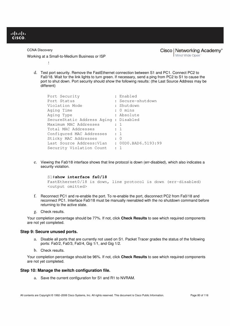
CCNA Discovery
Working at a Small-to-Medium Business or ISP
All contents are Copyright © 1992–2008 Cisco Systems, Inc. All rights reserved. This document is Cisco Public Information. Page 80 of 116
!
d. Test port security. Remove the FastEthernet connection between S1 and PC1. Connect PC2 to Fa0/18. Wait for the link lights to turn green. If necessary, send a ping from PC2 to S1 to cause the port to shut down. Port security should show the following results: (the Last Source Address may be different)
Port Security : Enabled
Port Status : Secure-shutdown
Violation Mode : Shutdown
Aging Time : 0 mins
Aging Type : Absolute
SecureStatic Address Aging : Disabled
Maximum MAC Addresses : 1
Total MAC Addresses : 1
Configured MAC Addresses : 1
Sticky MAC Addresses : 0
Last Source Address:Vlan : 00D0.BAD6.5193:99
Security Violation Count : 1
e. Viewing the Fa0/18 interface shows that line protocol is down (err-disabled), which also indicates a security violation.
S1#show interface fa0/18
FastEthernet0/18 is down, line protocol is down (err-disabled)
<output omitted>
f. Reconnect PC1 and re-enable the port. To re-enable the port, disconnect PC2 from Fa0/18 and reconnect PC1. Interface Fa0/18 must be manually reenabled with the no shutdown command before returning to the active state.
g. Check results.
Your completion percentage should be 77%. If not, click Check Results to see which required components are not yet completed.
Step 9: Secure unused ports.
a. Disable all ports that are currently not used on S1. Packet Tracer grades the status of the following ports: Fa0/2, Fa0/3, Fa0/4, Gig 1/1, and Gig 1/2.
b. Check results.
Your completion percentage should be 96%. If not, click Check Results to see which required components are not yet completed.
Step 10: Manage the switch configuration file.
a. Save the current configuration for S1 and R1 to NVRAM.

CCNA Discovery
Working at a Small-to-Medium Business or ISP
All contents are Copyright © 1992–2008 Cisco Systems, Inc. All rights reserved. This document is Cisco Public Information. Page 81 of 116
b. Back up the startup configuration file on S1 and R1 by uploading them to Server. Verify that Server has the R1-confg and S1-confg files.
c. Check results.
Your completion percentage should be 100%. If not, click Check Results to see which required components are not yet completed.

CCNA Discovery
Working at a Small-to-Medium Business or ISP
All contents are Copyright © 1992–2008 Cisco Systems, Inc. All rights reserved. This document is Cisco Public Information. Page 82 of 116
9.2.5.3: WAN Encapsulation Mismatches
Topology Diagram
Objectives
• Configure PPP encapsulation on all serial interfaces.
• Intentionally break and restore PPP encapsulation.
Background / Preparation
In this activity, you will learn how to configure PPP encapsulation on serial links. You will also examine encapsulation mismatches and learn how to correct the issue. For this activity, the password for both user EXEC and privileged EXEC modes is cisco.
Step 1: Configure PPP encapsulation on serial interfaces.
a. The default serial encapsulation on Cisco routers is HDLC. Use the show interface command on any of the serial interfaces to view the current encapsulation.
R1#show interface serial0/0/0
Serial0/0/0 is up, line protocol is up (connected)
Hardware is HD64570
Internet address is 10.1.1.1/30
CCNA Discovery
Working at a Small-to-Medium Business or ISP
All contents are Copyright © 1992–2008 Cisco Systems, Inc. All rights reserved. This document is Cisco Public Information. Page 83 of 116
MTU 1500 bytes, BW 1544 Kbit, DLY 20000 usec, rely 255/255, load
1/255
Encapsulation HDLC, loopback not set, keepalive set (10 sec)
<output omitted>
b. To change the encapsulation type on the link between R1 and R2, use the encapsulation ppp command for the serial 0/0/0 interface. Observe the effects.
R1(config)#interface serial 0/0/0
R1(config-if)#encapsulation ppp
%LINEPROTO-5-UPDOWN: Line protocol on Interface Serial0/0/0, changed
state to down
c. What happens when one end of the serial link is encapsulated with PPP and the other end of the link is encapsulated with HDLC? What would happen if PPP encapsulation was configured on each end of the serial link? To see what happens, configure the encapsulation on the serial 0/0/0 interface of R2 to PPP.
d. This time change the encapsulation from HDLC to PPP on both ends of the serial link between R2 and R3.
e. When does the line protocol on the serial link come up?
f. To verify that PPP is now the encapsulation on the serial interfaces, issue the show interface command for each serial interface.
Step 2: Examine the WAN encapsulation mismatches.
a. Return both serial interfaces on R2 to their default HDLC encapsulation using the encapsulation hdlc command.
b. What happened to the serial interfaces on R2?
c. Return both serial interfaces on R2 to PPP encapsulation.
d. Your completion percentage should be 100 percent. If not, click Check Results to see which required components are not yet completed.
Reflection
a. Why is it important to make sure encapsulation across a serial link is identical on both ends?
b. Because HDLC is the default encapsulation, is there another command that can be used to revert from PPP to HDLC other than encapsulation hdlc?
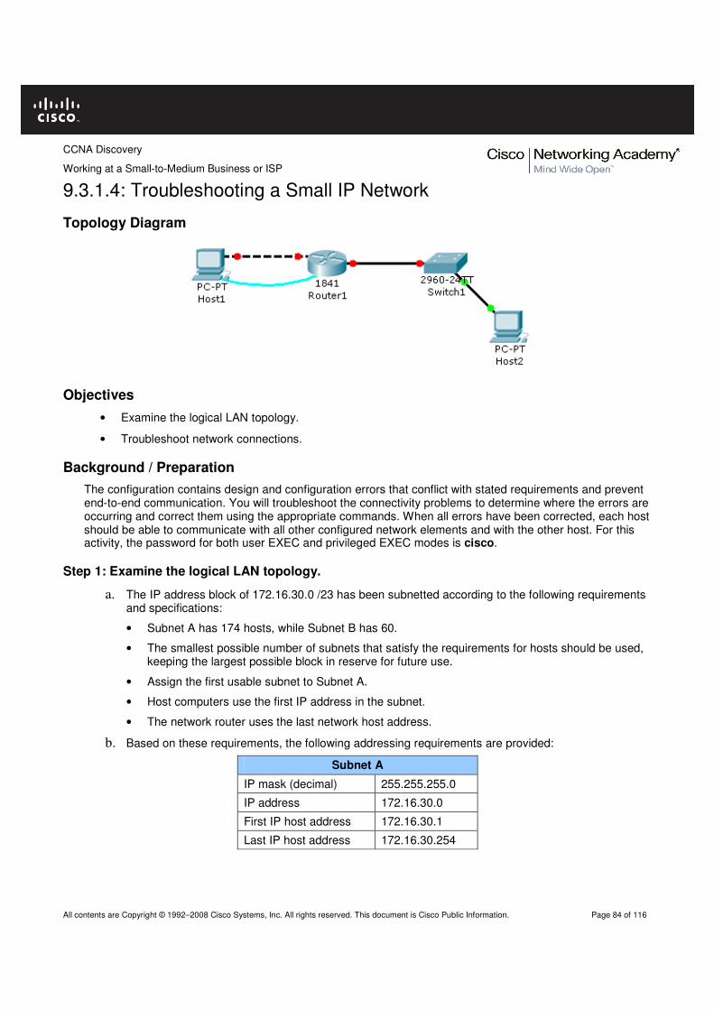
CCNA Discovery
Working at a Small-to-Medium Business or ISP
All contents are Copyright © 1992–2008 Cisco Systems, Inc. All rights reserved. This document is Cisco Public Information. Page 84 of 116
9.3.1.4: Troubleshooting a Small IP Network
Topology Diagram
Objectives
• Examine the logical LAN topology.
• Troubleshoot network connections.
Background / Preparation
The configuration contains design and configuration errors that conflict with stated requirements and prevent end-to-end communication. You will troubleshoot the connectivity problems to determine where the errors are occurring and correct them using the appropriate commands. When all errors have been corrected, each host should be able to communicate with all other configured network elements and with the other host. For this activity, the password for both user EXEC and privileged EXEC modes is cisco.
Step 1: Examine the logical LAN topology.
a. The IP address block of 172.16.30.0 /23 has been subnetted according to the following requirements and specifications:
• Subnet A has 174 hosts, while Subnet B has 60.
• The smallest possible number of subnets that satisfy the requirements for hosts should be used, keeping the largest possible block in reserve for future use.
• Assign the first usable subnet to Subnet A.
• Host computers use the first IP address in the subnet.
• The network router uses the last network host address.
b. Based on these requirements, the following addressing requirements are provided:
Subnet A
IP mask (decimal) 255.255.255.0
IP address 172.16.30.0
First IP host address 172.16.30.1
Last IP host address 172.16.30.254
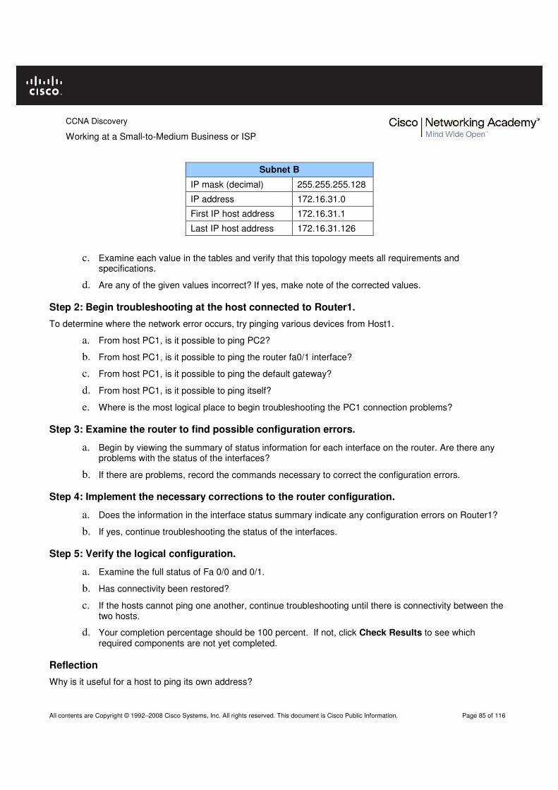
CCNA Discovery
Working at a Small-to-Medium Business or ISP
All contents are Copyright © 1992–2008 Cisco Systems, Inc. All rights reserved. This document is Cisco Public Information. Page 85 of 116
Subnet B
IP mask (decimal) 255.255.255.128
IP address 172.16.31.0
First IP host address 172.16.31.1
Last IP host address 172.16.31.126
c. Examine each value in the tables and verify that this topology meets all requirements and specifications.
d. Are any of the given values incorrect? If yes, make note of the corrected values.
Step 2: Begin troubleshooting at the host connected to Router1.
To determine where the network error occurs, try pinging various devices from Host1.
a. From host PC1, is it possible to ping PC2?
b. From host PC1, is it possible to ping the router fa0/1 interface?
c. From host PC1, is it possible to ping the default gateway?
d. From host PC1, is it possible to ping itself?
e. Where is the most logical place to begin troubleshooting the PC1 connection problems?
Step 3: Examine the router to find possible configuration errors.
a. Begin by viewing the summary of status information for each interface on the router. Are there any problems with the status of the interfaces?
b. If there are problems, record the commands necessary to correct the configuration errors.
Step 4: Implement the necessary corrections to the router configuration.
a. Does the information in the interface status summary indicate any configuration errors on Router1?
b. If yes, continue troubleshooting the status of the interfaces.
Step 5: Verify the logical configuration.
a. Examine the full status of Fa 0/0 and 0/1.
b. Has connectivity been restored?
c. If the hosts cannot ping one another, continue troubleshooting until there is connectivity between the two hosts.
d. Your completion percentage should be 100 percent. If not, click Check Results to see which required components are not yet completed.
Reflection
Why is it useful for a host to ping its own address?

CCNA Discovery
Working at a Small-to-Medium Business or ISP
All contents are Copyright © 1992–2008 Cisco Systems, Inc. All rights reserved. This document is Cisco Public Information. Page 86 of 116
9.3.4.5: Troubleshooting DHCP and NAT
Topology Diagram
Objectives
• Find and correct network errors.
• Document the corrected network.
Background / Preparation
The routers at your company were configured by an inexperienced network engineer. Several errors in the configuration have resulted in connectivity issues. Your boss has asked you to troubleshoot and correct the configuration errors and document your work. Using your knowledge of DHCP, NAT, and standard testing methods, find and correct the errors. Make sure all clients have full connectivity.
NAT Configuration
• The www.customer.com server at 172.16.20.254 is accessible by the Internet host at IP address 209.165.201.30.
• Dynamic NAT is configured with the name NAT_POOL for the range of IP addresses from 209.165.201.9 to 209.165.201.14 using a /29 mask.
• All hosts connected to the R1 LANs are translated using the NAT_POOL, and PAT is enabled.
• Appropriate interfaces are configured as either inside or outside NAT interfaces.
DHCP Configuration
• R1 is the DHCP server for the two directly connected LANS: 172.16.10.0/24 and 172.16.11.0/24.
• The first three IP addresses are excluded from DHCP offers.

CCNA Discovery
Working at a Small-to-Medium Business or ISP
All contents are Copyright © 1992–2008 Cisco Systems, Inc. All rights reserved. This document is Cisco Public Information. Page 87 of 116
• The default gateway is the closest router interface for each host.
• The DNS server is 172.16.20.254.
Note: Switch between Realtime and Simulation mode to accelerate the process of convergence. The network is converged when PC2 receives IP addressing configuration from the DHCP server.
Addressing Table
Device Interface IP Address Subnet Mask
R1 S0/0/0 172.16.0.1 255.255.255.252
Fa0/0 172.16.10.1 255.255.255.0
Fa0/1 172.16.11.1 255.255.255.0
R2 S0/0/0 172.16.0.2 255.255.255.252
S0/0/1 209.165.201.1 255.255.255.252
Fa0/0 172.16.20.1 255.255.255.0
ISP S0/0/1 209.165.201.2 255.255.255.252
Step 1: Find and correct network errors.
Use troubleshooting commands to discover errors and then correct them. When all errors are corrected, you should be able to ping from PC1 and PC2 to ISP. ISP should be able to ping the inside web server at its public IP address. Your completion percentage should be 100 percent. If not, continue troubleshooting to see which required components are not yet completed.
Step 2: Document the corrected network.
On each router, issue the show run command and capture the configurations.

CCNA Discovery
Working at a Small-to-Medium Business or ISP
All contents are Copyright © 1992–2008 Cisco Systems, Inc. All rights reserved. This document is Cisco Public Information. Page 88 of 116
9.4.1.4: Applying Routing Table Principles
Topology Diagram
Objectives
Recognize three important routing principles:
• A router makes decisions based on the information in the routing table.
• If one router has a complete routing table, this does not mean other routers have the same information.
• Routing information about a path from one network to another does not provide routing information about the reverse or return path.
Background / Preparation
Packets are forwarded through the network from one router to another router on a hop-by-hop basis. Each router makes an independent forwarding decision based on its knowledge of destination paths. Although packets may reach the destination network, the return path may be unknown to the destination router. When this occurs, the router is unable to route traffic back to the source. This is also known as “black hole” routing.

CCNA Discovery
Working at a Small-to-Medium Business or ISP
All contents are Copyright © 1992–2008 Cisco Systems, Inc. All rights reserved. This document is Cisco Public Information. Page 89 of 116
Addressing Table
Device Interface IP Address Subnet Mask Default Gateway
R1 Fa0/0 192.168.1.1 255.255.255.0 N/A
Fa0/1 192.168.2.1 255.255.255.0 N/A
R2 Fa0/0 192.168.2.2 255.255.255.0 N/A
S0/0/0 192.168.7.1 255.255.255.0 N/A
S0/0/1 192.168.3.1 255.255.255.0 N/A
R3 Fa0/0 192.168.4.1 255.255.255.0 N/A
S0/0/0 192.168.5.1 255.255.255.0 N/A
S0/0/1 192.168.3.2 255.255.255.0 N/A
R4 Fa0/0 192.168.6.1 255.255.255.0 N/A
S0/0/0 192.168.7.2 255.255.255.0 N/A
S0/0/1 192.168.5.2 255.255.255.0 N/A
PC1 NIC 192.168.1.10 255.255.255.0 192.168.1.1
PC2 NIC 192.168.1.20 255.255.255.0 192.168.1.1
PC3 NIC 192.168.4.10 255.255.255.0 192.168.4.1
PC4 NIC 192.168.6.10 255.255.255.0 192.168.6.1
Step 1: Determine why PC1 cannot successfully ping PC3.
a. Ping PC3 from PC1. Note that the ping is not successful.
b. Use the show ip route command to check the routing table on R1 to determine the problem.
c. Do you see a route in the routing table for 192.168.4.0?
d. Enter a static route on R1 for the destination network 192.168.4.0.
R1#configure terminal
R1(config)#ip route 192.168.4.0 255.255.255.0 192.168.2.2
R1(config)#end
e. Use the show ip route command to check the routing table on R1. Does the table now have a route to 192.168.4.0?
f. At the command prompt on PC1, ping 192.168.4.10. Note that the ping is not successful.
Step 2: View the ping from PC1 to PC3 in Simulation mode.
a. Change from Realtime to Simulation mode. Select the Simulation tab, located behind Realtime in the lower right corner.
b. Filter the traffic so that only ICMP packets are viewed. In Simulation mode, click the Edit Filters button. Select the Show All/None box to clear all the boxes, and then select ICMP.
CCNA Discovery
Working at a Small-to-Medium Business or ISP
All contents are Copyright © 1992–2008 Cisco Systems, Inc. All rights reserved. This document is Cisco Public Information. Page 90 of 116
c. Select the source and destination devices for the simulation. Above the Simulation mode icon, there are two envelope icons. Click the Add Simple PDU (P) envelope. Designate PC1 as the source of the ICMP traffic by clicking on PC1 in the workspace. Designate PC3 as the destination host.
d. Start the simulation by clicking the Auto Capture / Play button. This starts the ping using ICMP between the PCs.
e. Note that R1 is sending the ICMP traffic to R3. R3 is forwarding the ICMP traffic to PC3. PC3 is responding by sending ICMP traffic back to R3. However, R3 is discarding the packets. What is causing the ping to fail at R3?
f. Exit Simulation mode by clicking on the Realtime mode icon.
Step 3: Resolve the routing issue on R3.
a. Because R3 is not returning the ICMP traffic to PC1, check the routing table on R3.
b. Do you see a route in the routing table for 192.168.1.0?
c. Enter a static route on R3 for the destination network 192.168.1.0.
R3#configure terminal
R3(config)#ip route 192.168.1.0 255.255.255.0 Serial 0/0/1
R3(config)#end
d. Use the show ip route command to check the routing table on R3. Does the table now have a route to 192.168.1.0?
e. At the command prompt on PC1, ping 192.168.4.10. The ping should be successful. If not, retrace your steps and troubleshoot to resolve the problem.
Step 4: View the ping from PC1 to PC3 in Simulation mode.
a. Create a new scenario for this second simulation by clicking the New box under Scenario 0. This changes the drop-down menu to Scenario 1.
b. Filter the traffic so that only ICMP packets are viewed. Filter the traffic so that only ICMP packets are viewed. In Simulation mode, click on the Edit Filters button. Select the Show All/None box to clear all the boxes, and then select ICMP.
c. Select the source and destination devices for the simulation. Click the Add Simple PDU (P) envelope. Designate PC1 as the source of the ICMP traffic and PC3 as the destination host.
d. Start the simulation by clicking the Auto Capture / Play button. This starts the ping using ICMP between the PCs.
e. Note that R1 is sending the ICMP traffic to R3. R3 is forwarding the ICMP traffic to PC3. PC3 is responding by sending ICMP traffic back to R3. R3 is returning the ICMP traffic to R1. R1 is forwarding the reply to PC1. The routing issues have been resolved.
f. Exit Simulation mode by clicking on the Realtime mode icon.
g. Click the Check Results tab to verify that you have correctly completed the activity.

CCNA Discovery
Working at a Small-to-Medium Business or ISP
All contents are Copyright © 1992–2008 Cisco Systems, Inc. All rights reserved. This document is Cisco Public Information. Page 91 of 116
9.4.2.3: Configuring RIPv2 (Challenge)
Topology Diagram
Objectives
• Create an efficient IP address design based on the requirements.
• Assign appropriate addresses to interfaces and document the addresses.
• Configure and verify RIPv2 on routers.
• Test and verify full connectivity.
• Document the network implementation.
Background / Preparation
In this activity, you will be given a network address that must be subnetted to complete the addressing of the network. Create equal size subnets for each of the individual LANs. A combination of RIPv2 and static routing is required so that hosts on networks that are not directly connected can communicate with each other.
Step 1: Subnet the address space.
a. Examine the following addressing requirements:
• The ISP LAN uses the 209.165.200.224/27 network.
• The link between ISP and HQ uses the 209.165.202.128/27 network.
• The 192.168.40.0/24 network is subnetted for all other addresses in the network.
• The HQ LAN 1 requires 20 host IP addresses.
• The HQ LAN 2 requires 28 host IP addresses.

CCNA Discovery
Working at a Small-to-Medium Business or ISP
All contents are Copyright © 1992–2008 Cisco Systems, Inc. All rights reserved. This document is Cisco Public Information. Page 92 of 116
• The BRANCH LAN 1 requires 15 host IP addresses.
• The BRANCH LAN 2 requires 18 host IP addresses.
• The link between HQ and BRANCH requires an IP address at each end.
b. Consider the following questions when creating your network design:
• How many subnets need to be created from the 192.168.40.0/24 network?
• What is the subnet mask that can provide the necessary number of sub-networks, each subnet large enough to support the requirements?
• How many total IP addresses are required from the 192.168.40.0/24 network?
• What is the maximum number of host addresses that can be supported on each subnet?
• How many addresses are left on each subnet to support future growth?
c. Assign subnetwork addresses to the topology.
• Assign subnet 0 of the 192.168.40.0 network to the HQ LAN1 subnet.
• Assign subnet 1 of the 192.168.40.0 network to the HQ LAN2 subnet.
• Assign subnet 2 of the 192.168.40.0 network to the BRANCH LAN1 subnet.
• Assign subnet 3 of the 192.168.40.0 network to the BRANCH LAN2 subnet.
• Assign subnet 4 of the 192.168.40.0 network to the link between the HQ and BRANCH routers.
Step 2: Determine interface addresses.
a. Assign the first valid host address in the 209.165.200.224/27 network to the LAN interface on the ISP router.
b. Assign the last valid host address in 209.165.200.224/27 network to PC5.
c. Assign the first valid host address in the 209.165.202.128/27 network to the WAN interface of ISP.
d. Assign the last valid host address in the 209.165.202.128/27 network to the serial 0/0/1 interface of HQ.
e. Assign the first valid host address in the HQ LAN1 network to the LAN1 interface of HQ.
f. Assign the last valid host address in the HQ LAN1 network to PC3.
g. Assign the first valid host address in the HQ LAN2 network to the LAN2 interface of HQ.
h. Assign the last valid host address in the HQ LAN2 network to PC4.
i. Assign the first valid host address in the BRANCH LAN1 network to the LAN1 interface of BRANCH.
j. Assign the last valid host address in the BRANCH LAN1 network to PC1.
k. Assign the first valid host address in the BRANCH LAN2 network to the LAN2 interface of BRANCH.
l. Assign the last valid host address in the BRANCH LAN2 network to PC2.
m. Asssign the first valid host address in the HQ/BRANCH WAN link to the serial 0/0/0 interface of HQ.
n. Assign the last valid host address in the HQ/BRANCH WAN link to the serial 0/0/0 interface of BRANCH.
CCNA Discovery
Working at a Small-to-Medium Business or ISP
All contents are Copyright © 1992–2008 Cisco Systems, Inc. All rights reserved. This document is Cisco Public Information. Page 93 of 116
Step 3: Perform basic router configurations for the BRANCH, HQ, and ISP routers.
a. Configure the router host name.
b. Disable DNS lookup.
c. Configure an EXEC mode password.
d. Configure a message-of-the-day banner.
e. Configure the password cisco for console connections.
f. Configure a password cisco for vty connections.
Step 4: Configure and activate the serial and Fast Ethernet interfaces.
a. Configure the interfaces on BRANCH, HQ, and ISP with the IP addresses you assigned in Step 2.
b. Set BRANCH S0/0/0 with the clock rate of 56000.
c. Set HQ S0/0/1 with the clock rate of 56000.
d. Configure the Ethernet interfaces of PC1, PC2, PC3, PC4, and PC5 with the IP addresses you assigned in Step 2.
e. Save the running configuration to the NVRAM of the router.
Step 5: Verify connectivity to the next hop device.
You should not have connectivity between end devices yet. However, you can test connectivity between two routers and between an end device and its default gateway.
a. Verify that BRANCH can ping across the WAN link to HQ, and that HQ can ping across the WAN link it shares with ISP.
b. Verify that PC1, PC2, PC3, PC4, and PC5 can ping their respective default gateways.
Step 6: Configure RIPv2 routing on the BRANCH router.
Consider the networks that need to be included in the RIP updates that are sent out by BRANCH.
a. Which networks are present in the BRANCH routing table? List the networks with slash notation.
b. Which commands are required to enable RIPv2 and include the connected networks in the routing updates? Configure BRANCH with the correct networks.
c. Are there any router interfaces that do not need to have RIP updates sent out? If so, disable RIP updates on these interfaces with the appropriate command.
d. A static default route is needed to send packets with destination addresses that are not in the routing table to HQ. Configure a static default route using the outbound interface.
Step 7: Configure RIPv2 and static routing on HQ.
Consider the type of static routing that is needed on HQ.
a. Which networks are present in the HQ routing table? List the networks with slash notation.
b. A static default route is needed to send packets with destination addresses that are not in the routing table to ISP. Configure a static default route using the outbound interface.

CCNA Discovery
Working at a Small-to-Medium Business or ISP
All contents are Copyright © 1992–2008 Cisco Systems, Inc. All rights reserved. This document is Cisco Public Information. Page 94 of 116
c. Enable RIPv2 and include the LAN1 and LAN2 networks and the link between HQ and BRANCH in the routing updates.
d. Disable RIP updates on interfaces if necessary.
Step 8: Configure static routing on the ISP router.
In a real-world implementation of this topology, you would not be configuring the ISP router. However, your service provider is an active partner in solving your connectivity needs. Service provider administrators are human, and make mistakes. Therefore, it is important that you understand the types of errors an ISP could make that would cause your network to lose connectivity.
Static routes are needed on ISP for traffic that is destined for the RFC 1918 addresses that are used on the BRANCH LANs, HQ LANs, and the link between the BRANCH and HQ routers. Use the outbound interface for the static routing. Which commands are used on the ISP router to accomplish this?
Step 9: Verify the configurations.
Test the connectivity between the following devices. If any of the pings fail, troubleshoot.
• From PC1, is it possible to ping PC3?
• From PC1, is it possible to ping PC5?
• From PC4, is it possible to ping PC5?
Your completion percentage should be 100 percent. If not, continue troubleshooting to determine which required components are not yet completed.
Reflection
a. What routes are present in the routing table of the BRANCH router?
b. What is the gateway of last resort in the routing table of BRANCH?
c. What routes are present in the routing table of the HQ router?
d. What networks are present in the routing table of ISP?
e. What networks are present in the RIP updates sent from HQ?
f. What networks are present in the RIP updates sent from BRANCH?
g. How would using VLSM change the IP network addressing scheme?
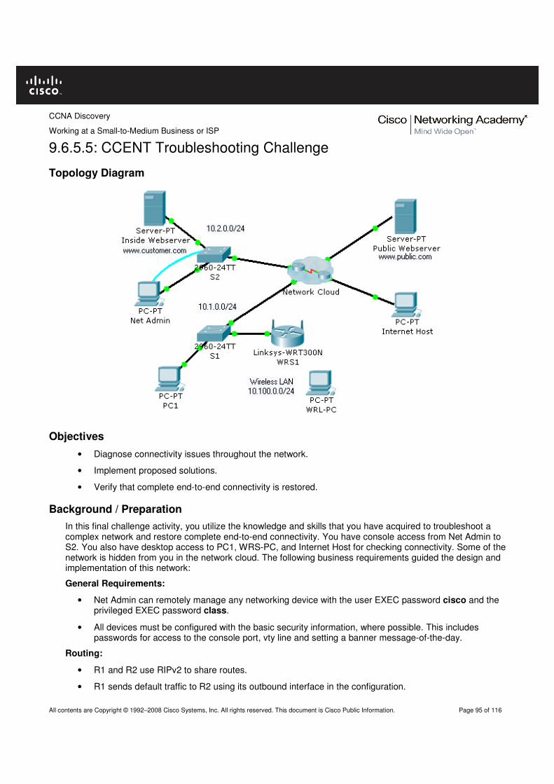
CCNA Discovery
Working at a Small-to-Medium Business or ISP
All contents are Copyright © 1992–2008 Cisco Systems, Inc. All rights reserved. This document is Cisco Public Information. Page 95 of 116
9.6.5.5: CCENT Troubleshooting Challenge
Topology Diagram
Objectives
• Diagnose connectivity issues throughout the network.
• Implement proposed solutions.
• Verify that complete end-to-end connectivity is restored.
Background / Preparation
In this final challenge activity, you utilize the knowledge and skills that you have acquired to troubleshoot a complex network and restore complete end-to-end connectivity. You have console access from Net Admin to S2. You also have desktop access to PC1, WRS-PC, and Internet Host for checking connectivity. Some of the network is hidden from you in the network cloud. The following business requirements guided the design and implementation of this network:
General Requirements:
• Net Admin can remotely manage any networking device with the user EXEC password cisco and the privileged EXEC password class.
• All devices must be configured with the basic security information, where possible. This includes passwords for access to the console port, vty line and setting a banner message-of-the-day.
Routing:
• R1 and R2 use RIPv2 to share routes.
• R1 sends default traffic to R2 using its outbound interface in the configuration.
CCNA Discovery
Working at a Small-to-Medium Business or ISP
All contents are Copyright © 1992–2008 Cisco Systems, Inc. All rights reserved. This document is Cisco Public Information. Page 96 of 116
• R1 dynamically assigns IP addresses from the 10.1.0.0/24 address space to wired PCs attached to S1. The first five addresses are excluded from the pool. The Inside Web Server at 10.2.0.25 is assigned as the DNS server.
• R2 sends default traffic to the ISP using its outbound interface in the configuration.
• R2 statically translates the private address of the Inside Web Server to the global IP address 209.165.202.129.
• R2 uses the IP address of the S0/0/1 interface and PAT to translate all other inside traffic bound for outside destinations.
• R2 and the ISP use PPP for the shared serial data link.
Switching:
• S1 and S2 are accessible through management interfaces from Net Admin.
• Port security on S2 is enforced. Only one MAC address can “stick” to a given interface. Security violations automatically disable a port.
Wireless:
• The Internet Connection Type for WRS1 is statically assigned, including the DNS server address.
• The wireless LAN uses the subnet 10.100.0.0/24 to dynamically assign addresses to wireless hosts.
• The wireless LAN uses WEP key 1234567890.
Note: The activity initially opens with a partial completion percentage. However, after all the links turn green and you begin pinging from Net Admin, the percentage changes to 0%. The steps are a suggested approach to troubleshooting the connectivity issues.
Step 1: Test Connectivity
a. From Net Admin, PC1, WRS-PC, and Internet Host, test connectivity across the network to gather information about where possible problems might exist.
b. Note: With full end-to-end connectivity, Internet Host should only be able to access the Inside Web Server at www.customer.com.
c. Document where connectivity fails.
Step 2: Access the network through Net Admin.
a. Net Admin is connected to S2 through both its Fast Ethernet port and its RS232 (console) port. Notice that the link lights for the LAN connection are red. Use the Net Admin console connection to log in to S2 and troubleshoot the problem. All networking devices use cisco for the user EXEC password and class for the privileged EXEC password.
b. What is the problem with the Net Admin LAN connection?
c. What solution would fix the problem? The solution must match the business requirements.
d. Implement the solution.
CCNA Discovery
Working at a Small-to-Medium Business or ISP
All contents are Copyright © 1992–2008 Cisco Systems, Inc. All rights reserved. This document is Cisco Public Information. Page 97 of 116
Step 3: Access the default gateway for Net Admin.
a. Close the terminal session on S2. The Net Admin LAN connection should now have green lights. If the connection at S2 is still amber, wait for it to turn green.
b. Open a command prompt on Net Admin. What is the address of the default gateway?
c. Ping the default gateway. This ping should be successful. Note: Net Admin should also be able to ping the Inside Web Server at www.customer.com.
d. Telnet to the default gateway.
Step 4: Investigate R2 connectivity.
a. Use show commands to determine the current state of the configuration on R2.
b. According to the descriptions, which interface connects to the ISP and to R1?
c. What is the status of the serial interfaces?
d. What routes does R2 have in its routing table?
e. Cisco devices can use a proprietary protocol to gather information about other directly connected Cisco devices. What is this protocol, and is it currently active on R2?
Step 5: Restore connectivity to the ISP.
a. What solution would correct the connectivity to the ISP?
b. Implement the solution, and then test connectivity by pinging the ISP address 209.165.201.1.
c. R2 cannot yet ping the Public Web Server. Why? What is the solution?
d. Implement the solution and make sure that the business requirements for default traffic are taken into account.
e. R2 should now be able to ping the Public Web Server at www.public.com. Note: Internet Host still cannot ping the Inside Web Server and Net Admin cannot ping past R2. You will solve these connectivity issues later in the activity.
Step 6: Get information about R1.
a. Which command enables the proprietary Cisco protocol on R2 so that you can gather information about other directly connected Cisco devices?
CCNA Discovery
Working at a Small-to-Medium Business or ISP
All contents are Copyright © 1992–2008 Cisco Systems, Inc. All rights reserved. This document is Cisco Public Information. Page 98 of 116
b. Add the command to the R2 configuration. After it is activated, it may take a few minutes for R2 to receive updates from its directly connected Cisco neighbors. You should eventually be able to discover the IP address for R1. Which command displays the IP address for R1? What is the R1 IP address?
Step 7: Telnet to R1 and solve routing issues.
a. From the R2 command line, telnet to R1.
b. Use show commands to determine the current state of the configuration on R1.
c. What is the status of the configured interfaces?
d. What routes does R1 have in its routing table?
e. A fully converged routing table includes a RIP route pointing to the LAN attached to R2. There could be more than one reason for the lack of convergence in the R1 routing table. From the information gathered using show commands, why is the R1 routing table not converged? What solutions would work?
f. Implement the solutions.
g. Give RIP a few seconds to converge, and then verify that R1 now has a RIP route to the R2 LAN. R1 should be able to ping the Inside Web Server and Net Admin. However, R1 cannot yet ping the ISP.
Step 8: Troubleshoot PC1 connectivity.
a. Has PC1 dynamically received IP addressing from R1? If not, make the necessary adjustments to PC1 so that it requests IP addressing from R1.
b. Is the addressing received from R1 complete and correct according to the business requirements?
c. Implement the appropriate solutions to fix the dynamic configuration on PC1. Make sure that the same current pool name in the configuration is used.
d. Verify that PC1 now has the correct configuration according to the business requirements. PC1 should now be able to ping the Inside Web Server and Net Admin.
Step 9: Troubleshoot WRS-PCs connectivity.
a. Notice that WRS-PC is not wirelessly connected to WRS1. To troubleshoot the configuration on WRS1, you must use a wired connection to connect WRS1 and WRS-PC. Remove the wireless NIC on WRS-PC and replace it with an appropriate NIC for a wired connection to WRS1.
b. When WRS-PC is connected to WRS1, open a command prompt and enter the command to request IP addressing. After WRS-PC receives addressing from WRS1, open a Web Browser and type in the

CCNA Discovery
Working at a Small-to-Medium Business or ISP
All contents are Copyright © 1992–2008 Cisco Systems, Inc. All rights reserved. This document is Cisco Public Information. Page 99 of 116
default gateway address to access the Linksys Basic Setup web page. The administrative password is cisco123.
c. Verify that the configurations on the Basic Setup page match the business requirements. If there is an error, solve it.
d. Close the Linksys web page, and replace the wired NIC with a wireless NIC.
e. Access the wireless configuration on WRS-PC. Use the Linksys Wireless Network Monitor v1.0 to configure the wireless connection.
f. Verify that WRS-PC now has the correct configuration according to the business requirements. WRS-PC should be able to ping PC1, Inside Web Server, and Net Admin.
Step 10: Troubleshoot the NAT configuration on R2.
a. Currently, none of the end devices can ping the Public Web Server. In addition, the Internet Host cannot ping the Inside Web Server. R2 is the NAT firewall router.
b. Investigate the configuration on R2. According to the business requirements, what are the errors in the NAT configuration?
• • •
c. Implement the solutions necessary to fix the errors.
d. Your completion percentage should be 100 percent. If not, continue troubleshooting to determine which required components are not yet completed.
Step 11: Verify full end-to-end connectivity.
a. PC1, WRS-PC, and Net Admin should all now be able to access the Public Web Server.
b. The Internet Host should now be able to access the Inside Web Server.

CCNA Discovery
Working at a Small-to-Medium Business or ISP
All contents are Copyright © 1992–2008 Cisco Systems, Inc. All rights reserved. This document is Cisco Public Information. Page 100 of 116
10.0.1.2 Putting It All Together
Objective(s)
• Create an IP addressing plan for a small network.
• Implement a network equipment upgrade.
• Verify device configurations and network connectivity.
Background / Preparation
In this activity, you will play the role of an onsite installation and support technician from an ISP. You receive a work order specifying your responsibilities which include analyzing the customer’s existing network configuration and implementing a new configuration to improve network performance. You will use additional equipment as necessary and develop an IP subnetting scheme to address the customer’s needs. On an earlier site visit, one of the ISP technicians had created a diagram of the customer’s existing network as shown below.
The following equipment is required:
• ISP router with 2 Serial and one FastEthernet interface (preconfigured by instructor)
• Ethernet 2960 switch to connect to ISP router (preconfigured by instructor)
• Customer 1841 router (or other router with two FastEthernet interfaces and at least one Serial interface to connect to the ISP)
• Linksys WRT300N (or other Linksys that supports wireless)
• Ethernet 2960 switch to connect wired PCs
• Windows XP-based PC to act as wireless client (wireless NIC)
• Windows XP-based PC to act as wired client (Ethernet NIC)
• Cat 5 cabling as necessary
• Serial cabling as necessary
• ISP work order (in this lab)
• Device Configuration Checklist (in this lab)
• Network Equipment Installation Checklist (in this lab)
• Configuration Verification and Connectivity Checklist (in this lab)

CCNA Discovery
Working at a Small-to-Medium Business or ISP
All contents are Copyright © 1992–2008 Cisco Systems, Inc. All rights reserved. This document is Cisco Public Information. Page 101 of 116
Part A - Review the existing network and customer work order.
Step 1: You have received the following work order from your manager at the ISP.
Review the work order to get a general understanding of what is to be done for the customer.
ABC-XYZ-ISP Inc.
Official Work Order
Customer: AnyCompany1 Date: _____________
Address: 1234 Fifth Street, Anytown,
Customer Contact: Fred Pennypincher, Chief Financial Officer
Phone number: 123-456-7890
Description of work to be performed
Upgrade the existing network by adding an 1841 router and standalone 2960 switch to
supplement and offload the existing Linksys WRT300N. The new switch will support
connections from wired clients on one subnet. The existing Linksys will support wireless clients
on another subnet. Configure the 1841 as a DHCP server for the wired network and the Linksys
which supports wireless users.
The wired and wireless client traffic from each subnet will be routed though the new 1841
customer router. The RIP v2 routing protocol is to be used between the 1841 and the ISP and the
encapsulation on the WAN link between is PPP. The customer router must use a static address
and the ISP router serial interface IP address it must communicate with is:
___________________________________
The ISP has an IP address of 10.100.1.5 /22 on the serial 0 interface.
Assigned to: Approved by:
Guy Netwiz Bill Broadband, ISP Manager
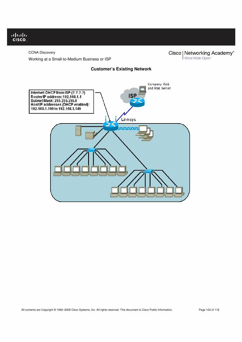
CCNA Discovery
Working at a Small-to-Medium Business or ISP
All contents are Copyright © 1992–2008 Cisco Systems, Inc. All rights reserved. This document is Cisco Public Information. Page 102 of 116
Customer’s Existing Network

CCNA Discovery
Working at a Small-to-Medium Business or ISP
All contents are Copyright © 1992–2008 Cisco Systems, Inc. All rights reserved. This document is Cisco Public Information. Page 103 of 116
Part B – Develop the subnet scheme.
The customer, AnyCompany1, has been assigned an IP address and subnet mask: 192.168.111.0 /24.
Develop a subnet scheme using this address that will allow the customer network to support two subnets of up to 30 clients each, and allow for growth to as many as 6 subnets in the future.
Subnet 1 (not subnet zero) will be used to provide a range of IP addresses for the wired users, which will connect to FastEthernet 0/0 interface on the Customer Router via the Cisco 2960 switch. Subnet 2 will be used to provide a range of IP addresses for the Linksys external Internet interface and the FastEthernet 0/1 interface on the Customer Router, which are linked.
The router IP addresses on the Fast Ethernet ports for both the wired and wireless network will be the first available IP address from the respective subnetwork. The IP address for the Linksys will be the second available address from the range assigned above.
The wireless network clients will use the default internal IP addressing (network 192.168.1.0 /24) assigned by the Linksys. The Linksys will use NAT/PAT to convert internal wireless client addresses to the external address. The internal wireless clients will not require a subnet from the base address.
Step 1: Determine the number of hosts and subnets.
a. The largest subnet must be able to support 30 hosts. To support that many hosts, the number
of host bits required is ______________.
b. What is the minimum number of subnets required for the new network design that also allows for future growth? _________
c. How many host ID bits are reserved for the subnet ID to allow for this number of subnets with each subnet having 30 hosts? _________
d. What is the maximum possible number of subnets with this scheme? ___________
Step 2: Calculate the custom subnet mask.
a. Now that the number of subnet ID bits is known, the subnet mask can be calculated. A class C network has a default subnet mask of 24 bits, or 255.255.255.0. What will the custom subnet mask be?
b. The custom subnet mask for this network will be _____._____._____._____, or /_____.
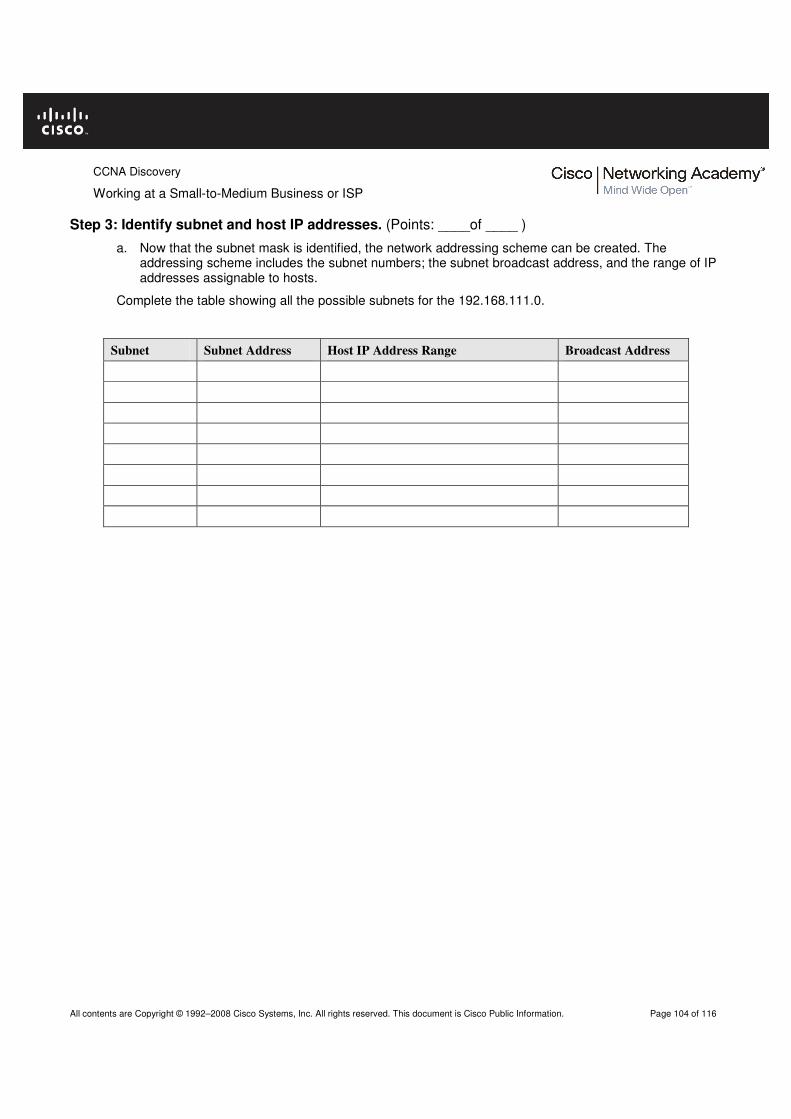
CCNA Discovery
Working at a Small-to-Medium Business or ISP
All contents are Copyright © 1992–2008 Cisco Systems, Inc. All rights reserved. This document is Cisco Public Information. Page 104 of 116
Step 3: Identify subnet and host IP addresses. (Points: ____of ____ )
a. Now that the subnet mask is identified, the network addressing scheme can be created. The addressing scheme includes the subnet numbers; the subnet broadcast address, and the range of IP addresses assignable to hosts.
Complete the table showing all the possible subnets for the 192.168.111.0.
Subnet Subnet Address Host IP Address Range Broadcast Address

CCNA Discovery
Working at a Small-to-Medium Business or ISP
All contents are Copyright © 1992–2008 Cisco Systems, Inc. All rights reserved. This document is Cisco Public Information. Page 105 of 116
Part C – Document network device interfaces and physical topology.
Step 1: Document the 1841 interfaces and Host IP addresses. (Points: ____of ____ )
Fill in the following table with the IP addresses, subnet masks and connection information for the customer router interfaces. If an interface is not used enter N/A. This information will be used in configuring the customer router. If you are using a router other than an 1841, use the interface chart at the end of the lab to determine the proper interface designations.
Interface
(1841)
IP Address / subnet mask Connects to device /
interface
Connects to device
IP Address (if applicable)
Serial 0/0/0
Serial 0/0/1
Fa 0/0
Fa 0/1
Step 2: Document the Linksys interfaces and host IP addresses. (Points: ____of ____ )
Fill in the following table with the IP addresses, subnet masks and connection information for the Linksys interfaces.
Interface
(Linksys)
IP Address / subnet mask Connects to device /
interface
Connects to device
IP Address (if applicable)
Internet Interface
(external address)
LAN gateway (internal address)
DHCP Wireless Hosts address range

CCNA Discovery
Working at a Small-to-Medium Business or ISP
All contents are Copyright © 1992–2008 Cisco Systems, Inc. All rights reserved. This document is Cisco Public Information. Page 106 of 116
Step 3: Diagram the upgraded network. (Points: ____of ____ )
In the space provided here, draw a physical network diagram, showing all network devices, PCs and cabling. Identify all devices and interfaces according to the interface chart and indicate the IP address and subnet mask (using /xx format) for each interface, based on the entries from the previous steps.

CCNA Discovery
Working at a Small-to-Medium Business or ISP
All contents are Copyright © 1992–2008 Cisco Systems, Inc. All rights reserved. This document is Cisco Public Information. Page 107 of 116
Part D – Configure devices and verify default settings.
Step 1: Verify default settings for the 1841 customer router.
a. Click on the customer router and verify that is in the factory default state.
Step 2: Configure the 1841 customer router. (Points: ____of ____ )
a. Use the following checklist to assist in configuring the 1841 customer router. Check off the configuration items as you complete them.
b. Display the running-config of the router.
Instructor Note: See running-config at end of lab
Device Configuration Checklist
Device Manuf. / Model Number: _______________________ IOS version: ______________________
Configuration Item Configuration value Notes / IOS Commands or SDM used
Configure the router host name
AnyCompany1
Configure passwords Console: cisco
Enable: cisco
Enable Secret: class
VTY terminals: cisco
Configure FastEthernet interface 0/0
IP Addr: ___________________
SN mask: __________________
Configure FastEthernet interface 0/1
IP Addr: ___________________
SN mask: __________________
Configure the WAN interface Serial 0/0/0
(ISP provides clock rate, encapsulation PPP)
IP Addr: ___________________
SN mask: __________________
Configure DHCP server for internal wired network
Subnet 1: ___________________
Configure Static route to the wireless network

CCNA Discovery
Working at a Small-to-Medium Business or ISP
All contents are Copyright © 1992–2008 Cisco Systems, Inc. All rights reserved. This document is Cisco Public Information. Page 108 of 116
Configure a default route to the ISP router
Display the running-config and verify all settings
Save running-config to startup-config
Step 3: Verify default settings for the Linksys and set the SSID. (Points: ____of ____ )
a. Click on the Linksys and verify that it is in the factory default state. The router internal IP address should be set to 192.168.1.1 and a subnet mask of 255.255.255.0. The DHCP address range should be 192.168.1.100 through 192.168.1.149. All security settings should be default, with no MAC filtering etc.
b. Change the default Service Set Identifier (SSID) of “linksys” to “AnyCompany1”
c. Change the Internet Connection Type to Static IP and configure the IP address, Subnet Mask, and Default Gateway to be compatible with the 1841 FastEthernet interface F0/1.
Step 4: Verify host PCs are DHCP clients. (Points: ____of ____ )
Click on each PC and use the Config > Global Settings option to verify that both the wired and wireless host PCs are set to obtain their IP addresses automatically via DHCP.
Part E – Connect network devices and verify connectivity.
Step 1: Connect the network devices. (Points: ____of ____ )
Use the following checklist to assist in connecting network devices using the proper cables. Check off the installation items as you complete them.
Network Equipment Installation Checklist
Devices connected From Device /Interface
To Device /Interface
Cable type
Connect the Linksys to the 1841.
Connect the 1841 to the ISP router
Connect the 1841 to the switch
Connect wired PC to switch
Configure Wireless SSID on both the PC and the Linksys Router.
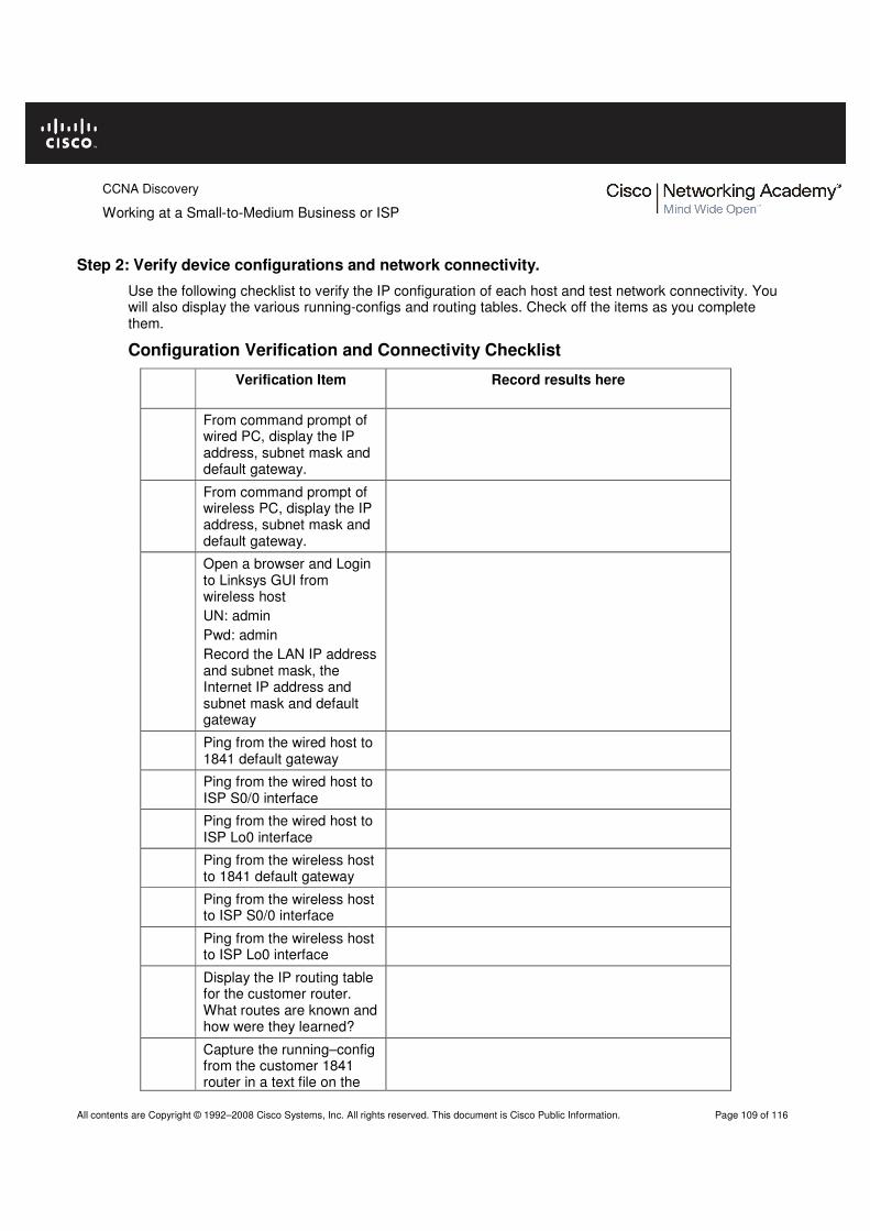
CCNA Discovery
Working at a Small-to-Medium Business or ISP
All contents are Copyright © 1992–2008 Cisco Systems, Inc. All rights reserved. This document is Cisco Public Information. Page 109 of 116
Step 2: Verify device configurations and network connectivity.
Use the following checklist to verify the IP configuration of each host and test network connectivity. You will also display the various running-configs and routing tables. Check off the items as you complete them.
Configuration Verification and Connectivity Checklist
Verification Item Record results here
From command prompt of wired PC, display the IP address, subnet mask and default gateway.
From command prompt of wireless PC, display the IP address, subnet mask and default gateway.
Open a browser and Login to Linksys GUI from wireless host
UN: admin
Pwd: admin
Record the LAN IP address and subnet mask, the Internet IP address and subnet mask and default gateway
Ping from the wired host to 1841 default gateway
Ping from the wired host to ISP S0/0 interface
Ping from the wired host to ISP Lo0 interface
Ping from the wireless host to 1841 default gateway
Ping from the wireless host to ISP S0/0 interface
Ping from the wireless host to ISP Lo0 interface
Display the IP routing table for the customer router. What routes are known and how were they learned?
Capture the running–config from the customer 1841 router in a text file on the

CCNA Discovery
Working at a Small-to-Medium Business or ISP
All contents are Copyright © 1992–2008 Cisco Systems, Inc. All rights reserved. This document is Cisco Public Information. Page 110 of 116
desktop to show to the instructor. Name the file using your initials.

CCNA Discovery
Working at a Small-to-Medium Business or ISP
All contents are Copyright © 1992–2008 Cisco Systems, Inc. All rights reserved. This document is Cisco Public Information. Page 111 of 116
CCNA Discovery 4.1.3 Working at a Small to Medium Business or ISP – Packet Tracer and E-Sim / CCENT Objectives Map
PT# Title Objectives CCENT / ICND1 Cert
Objectives
1.2.3.4 Interpreting Ping and Traceroute Output
• Distinguish the difference between successful and unsuccessful ping attempts.
• Distinguish the difference between successful and unsuccessful traceroute attempts.
802.1.8 Determine the path between two hosts across a network.
802.1.10 Identify and correct common network problems at layers 1,2,3 and 7 using a layered model approach.
1.3.1.3 Identifying Equipment to Meet Customer Requirements
• Select the appropriate interface cards for the needs and budget of an organization.
• Compare the trade-off between cost and flexibility.
• Add new equipment to accommodate expansion and allow for future growth.
802.1.2 Select the components required to meet a given network specification.
2.3.1.4 Troubleshooting and Resolving Network Issues
• Diagnose a network connectivity issue.
• Implement a proposed solution to restore network connectivity.
802.4.7 Verify device configuration and network connectivity using ping, traceroute, telnet, SSH or other utilities.
3.1.3.2 Creating Network Diagrams
• Investigate the customer network.
• Create a network inventory list. • Create a logical topology
diagram.
802.1.7 Interpret network diagrams.
3.3.3.4 Exploring Different LAN Switch Options
• Determine the cable types to use to connect all devices to the switch.
• Add appropriate modules to switches and routers.
• Connect the devices to the switch using the appropriate cable types.
802.2.1 Select the appropriate media, cables, ports, and connectors to connect switches to other network devices and hosts.
802.4.3 Select the appropriate media, cables, ports, and connectors to connect routers to other network devices and hosts.
3.3.4.3 Exploring Internetworking Devices
• Describe the different options available on an ISR and a router.
• Determine which options provide the needed connectivity.
• Add the correct modules and interfaces to the ISR and the router, and interconnect the devices.
802.2.1 Select the appropriate media, cables, ports, and connectors to connect switches to other network devices and hosts.
802.4.3 Select the appropriate media, cables, ports, and connectors to connect routers to

CCNA Discovery
Working at a Small-to-Medium Business or ISP
All contents are Copyright © 1992–2008 Cisco Systems, Inc. All rights reserved. This document is Cisco Public Information. Page 112 of 116
other network devices and hosts.
4.1.3.5 Implementing an IP Addressing Scheme
• Subnet an address space based on host requirements.
• Assign host addresses to devices.
• Configure devices with IP addressing.
• Verify the addressing configuration.
802.3.2 Create and apply an addressing scheme to a network.
802.3.3 Assign and verify valid IP addresses to hosts, servers, and networking devices in a LAN environment.
4.1.5.2 Communicating Between Subnets
• Describe how hosts on separate subnets communicate to share resources.
802.1.8 Determine the path between two hosts across a network.
802.3.10 Identify and correct IP addressing issues.
4.2.3.3 Examining Network Address Translation (NAT)
• Examine NAT processes as traffic traverses a NAT border router.
802.3.4 Explain the basic uses and operation of NAT in a small network connecting to one ISP.
5.3.1.3 E-Lab – Entering Command Modes
• Using the Cisco CLI explore the various configuration modes.
802.4.5 Access and utilize the router CLI to set basic parameters.
5.3.2.5
Exploring the Cisco IOS CLI
• Use the Cisco IOS CLI context-sensitive Help feature.
• Explore command shortcuts. • Learn about error detection
features.
• Use command history.
802.4.5 Access and utilize the router CLI to set basic parameters.
5.3.3.2 E-Lab – Viewing Router Interface Information
• Use the show run and show interface commands to answer questions about the router configuration.
802.4.12 Verify network status and router operation using basic utilities (ping, traceroute, Telnet, SSH, arp, ipconfig), SHOW & DEBUG commands.
5.3.3.3 Using the Cisco IOS Show Commands
• Use the Cisco IOS show commands.
802.4.12 Verify network status and router operation using basic utilities (ping, traceroute, telnet, SSH, arp, ipconfig), SHOW & DEBUG commands.
5.3.4.4 Performing an Initial Router Configuration
• Configure the router host name. • Configure passwords. • Configure banner messages. • Verify the router configuration.
802.4.5 Access and utilize the router CLI to set basic parameters.
5.3.5.3 E-Lab – Configuring a Serial Interface on Routers for Communication
• Configure the serial interfaces on two routers.
802.4.5 Access and utilize the router CLI to set basic parameters.
802.4.6 Connect, configure, and verify operation status of a device interface.
802.8.2 Configure and verify a

CCNA Discovery
Working at a Small-to-Medium Business or ISP
All contents are Copyright © 1992–2008 Cisco Systems, Inc. All rights reserved. This document is Cisco Public Information. Page 113 of 116
basic WAN serial connection.
5.3.5.4 Configuring Ethernet and Serial Interfaces
• Configure a LAN Ethernet interface.
• Configure a WAN serial interface.
• Verify the interface configurations.
802.4.6 Connect, configure, and verify operation status of a device interface.
802.8.2 Configure and verify a basic WAN serial connection.
5.3.6.2 Configuring a Default Route
• Configure a default route on a router.
802.4.8 Perform and verify routing configuration tasks for a static or default route given specific routing requirements.
5.3.7.2 Configuring a Cisco Router as a DHCP Server
• Configure the customer Cisco 1841 ISR as a DHCP server.
802.3.8 Configure, verify and troubleshoot DHCP and DNS operation on a router. (CLI/SDM)
5.3.8.3
Configuring Static NAT on a Cisco Router
• Configure the customer Cisco 1841 ISR to use NAT.
• Verify the configuration.
802.3.7 Enable NAT for a small network with a single ISP connection using SDM and verify operation using CLI and ping.
5.3.9.3 Backing Up a Cisco Router Configuration to a TFTP Server
• Save the current running configuration to the startup configuration.
• Back up the configuration to a TFTP server.
802.4.9 Manage IOS configuration files (save, edit, upgrade, restore).
5.4.4.2 Configuring a PPP Connection Between a Customer and an ISP
• Configure PPP as the encapsulation type on a serial interface.
• Verify the PPP configuration.
802.4.6 Connect, configure, and verify operation status of a device interface.
802.8.2 Configure and verify a basic WAN serial connection.
5.5.3.3 E-Lab – Configuring a Cisco 2960 switch
• Configure the basic settings on a Cisco Catalyst switch.
802.2.5 Perform, save and verify initial switch configuration tasks including remote access management.
5.5.3.4 Performing an Initial Switch Configuration
• Perform an initial configuration of a Cisco Catalyst 2960 switch.
802.2.5 Perform, save and verify initial switch configuration tasks including remote access management.
5.5.4.4 Connecting a Switch • Connect a switch to the network. • Verify the configuration on the
switch.
802.2.5 Perform, save and verify initial switch configuration tasks including remote access management.
802.2.6 Verify network status and switch operation using basic utilities (ping, traceroute, Telnet, SSH, arp and ipconfig), SHOW & DEBUG commands.
5.5.5.2 Using CDP as a Network Discovery
• Examine CDP show commands. • Examine CDP configuration
802.4.7 Verify device configuration and network

CCNA Discovery
Working at a Small-to-Medium Business or ISP
All contents are Copyright © 1992–2008 Cisco Systems, Inc. All rights reserved. This document is Cisco Public Information. Page 114 of 116
Tool commands. connectivity using ping, traceroute, telnet, SSH or other utilities.
6.1.1.5 Configuring Static and Default Routes
• Configure static routes on each router to allow communication between all clients.
• Test connectivity to ensure that each device can fully communicate with all other devices.
802.4.8 Perform and verify routing configuration tasks for a static or default route given specific routing requirements.
6.1.5.3 Configuring RIP • Configure routers using basic interface configuration commands.
• Enable RIP. • Verify the RIP configuration.
802.4.4 Configure, verify, and troubleshoot RIPv2.
8.2.2.3 Planning Network-based Firewalls
• Place firewalls in appropriate locations to satisfy security requirements.
802.6.2 Explain general methods to mitigate common security threats to network devices, hosts, and applications.
8.2.4.3 Configuring WEP on a Wireless Router
• Configure WEP security between a workstation and a Linksys wireless router.
802.5.3 Identify the basic parameters to configure on a wireless network to ensure that devices connect to the correct access point.
802.5.4 Compare and contrast wireless security features and capabilities of WPA security (open, WEP, WPA-1/2).
9.2.4.3 Configuring and Troubleshooting a Switched Network
• Establish console connection to the switch.
• Configure the host name and VLAN1.
• Use the help feature to configure the clock.
• Configure passwords and console/Telnet access.
• Configure login banners. • Configure the router. • Solve duplex and speed
mismatch problems. • Configure port security. • Secure unused ports.
• Manage the switch configuration file.
802.2.5 Perform, save and verify initial switch configuration tasks including remote access management.
802.2.6 Verify network status and switch operation using basic utilities (ping, traceroute, Telnet, SSH, arp and ipconfig), SHOW & DEBUG commands.
802.2.7 Implement and verify basic security for a switch (port security, deactivate ports).
9.2.5.3 WAN Encapsulation Mismatches
• Configure PPP encapsulation on all serial interfaces.
• Intentionally break and restore PPP encapsulation.
802.4.7 Verify device configuration and network connectivity using ping, traceroute, telnet, SSH or other
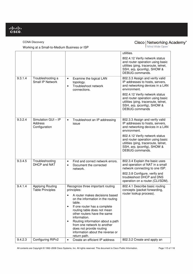
CCNA Discovery
Working at a Small-to-Medium Business or ISP
All contents are Copyright © 1992–2008 Cisco Systems, Inc. All rights reserved. This document is Cisco Public Information. Page 115 of 116
utilities.
802.4.12 Verify network status and router operation using basic utilities (ping, traceroute, telnet, SSH, arp, ipconfig), SHOW & DEBUG commands.
9.3.1.4 Troubleshooting a Small IP Network
• Examine the logical LAN topology.
• Troubleshoot network connections.
802.3.3 Assign and verify valid IP addresses to hosts, servers, and networking devices in a LAN environment.
802.4.12 Verify network status and router operation using basic utilities (ping, traceroute, telnet, SSH, arp, ipconfig), SHOW & DEBUG commands
9.3.2.4 Simulation GUI – IP Address Configuration
• Troubleshoot an IP addressing issue
802.3.3 Assign and verify valid IP addresses to hosts, servers, and networking devices in a LAN environment.
802.4.12 Verify network status and router operation using basic utilities (ping, traceroute, telnet, SSH, arp, ipconfig), SHOW & DEBUG commands.
9.3.4.5 Troubleshooting DHCP and NAT
• Find and correct network errors.
• Document the corrected network.
802.3.4 Explain the basic uses and operation of NAT in a small network connecting to one ISP.
802.3.8 Configure, verify and troubleshoot DHCP and DNS operation on a router.(CLI/SDM).
9.4.1.4 Applying Routing Table Principles
Recognize three important routing principles:
• A router makes decisions based on the information in the routing table.
• If one router has a complete routing table does not mean other routers have the same information.
• Routing information about a path from one network to another does not provide routing information about the reverse or return path.
802.4.1 Describe basic routing concepts (packet forwarding, router lookup process).
9.4.2.3 Configuring RIPv2 • Create an efficient IP address 802.3.2 Create and apply an

CCNA Discovery
Working at a Small-to-Medium Business or ISP
All contents are Copyright © 1992–2008 Cisco Systems, Inc. All rights reserved. This document is Cisco Public Information. Page 116 of 116
(Challenge) design based on the requirements.
• Assign appropriate addresses to interfaces and document the addresses.
• Configure and verify RIPv2 on routers.
• Test and verify full connectivity. • Document the network
implementation.
addressing scheme to a network.
802.3.3 Assign and verify valid IP addresses to hosts, servers, and networking devices in a LAN environment.
802.4.4 Configure, verify, and troubleshoot RIPv2.
9.6.5.5 CCENT Troubleshooting Challenge
• Diagnose connectivity issues throughout the network.
• Implement proposed solutions.
• Verify that complete end-to-end connectivity is restored.
802.2.6 Verify network status and switch operation using basic utilities (ping, traceroute, Telnet, SSH, arp and ipconfig), SHOW & DEBUG commands.
802.4.12 Verify network status and router operation using basic utilities (ping, traceroute, telnet, SSH, arp and ipconfig), SHOW & DEBUG commands.


