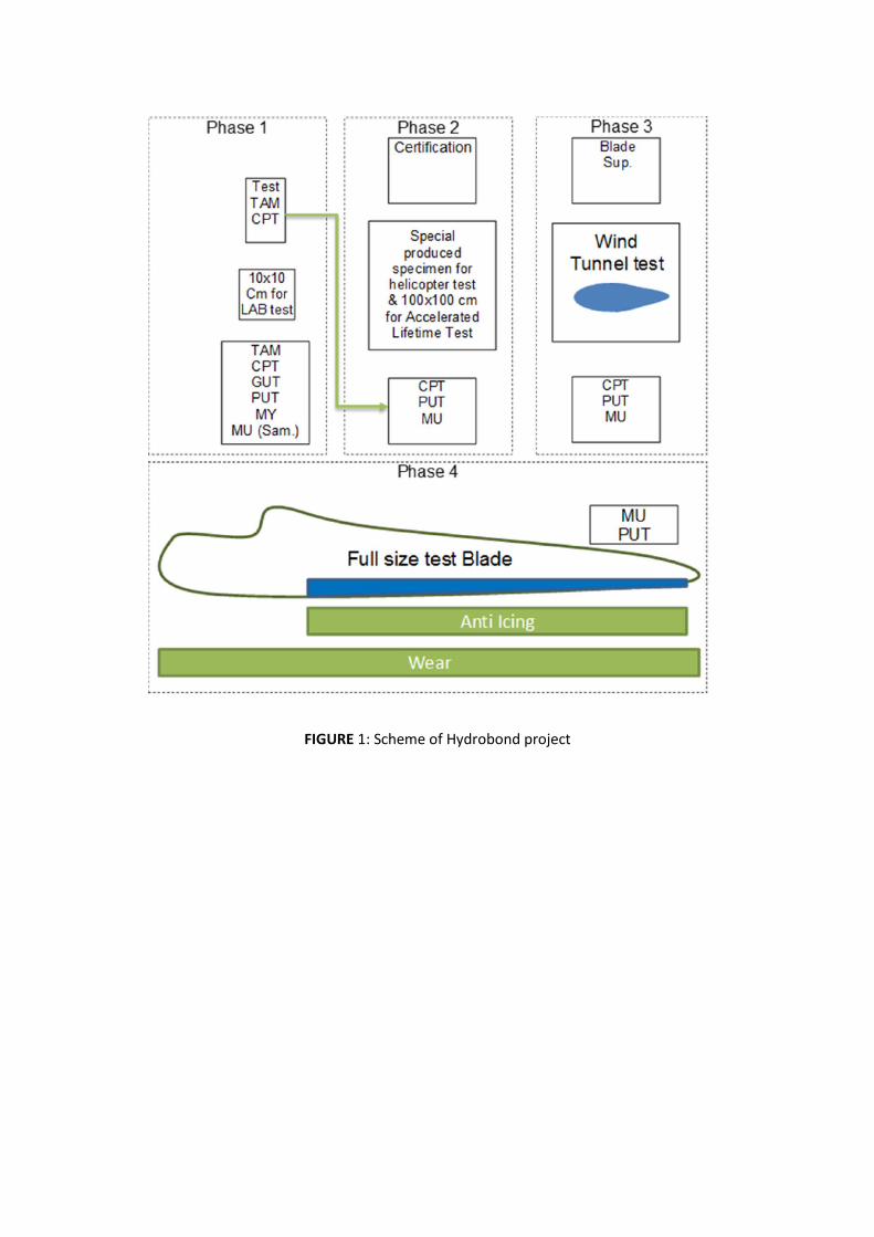
FIGURE 1: Scheme of Hydrobond project

FIGURE 2: (a) Accreted ice on the sample; (b) centrifugal ice adhesion test equipment and (c) water jet erosion test
c
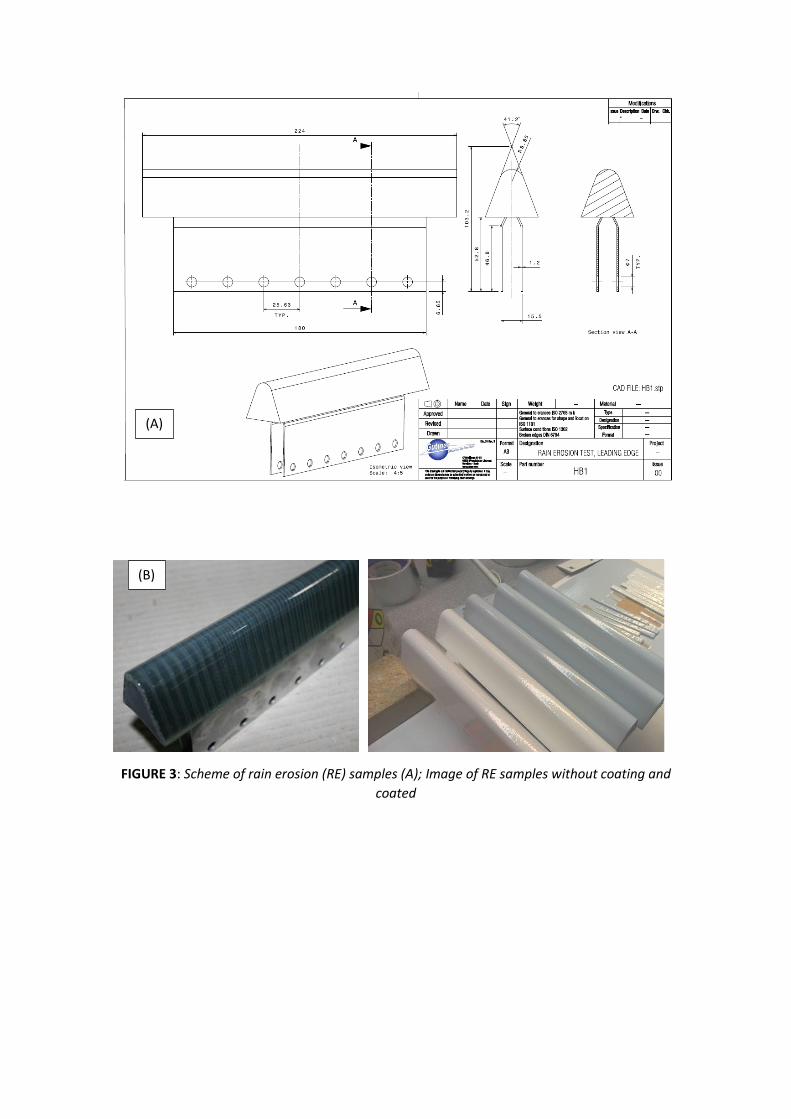
FIGURE 3: Scheme of rain erosion (RE) samples (A); Image of RE samples without coating and
coated
(A)
(B)
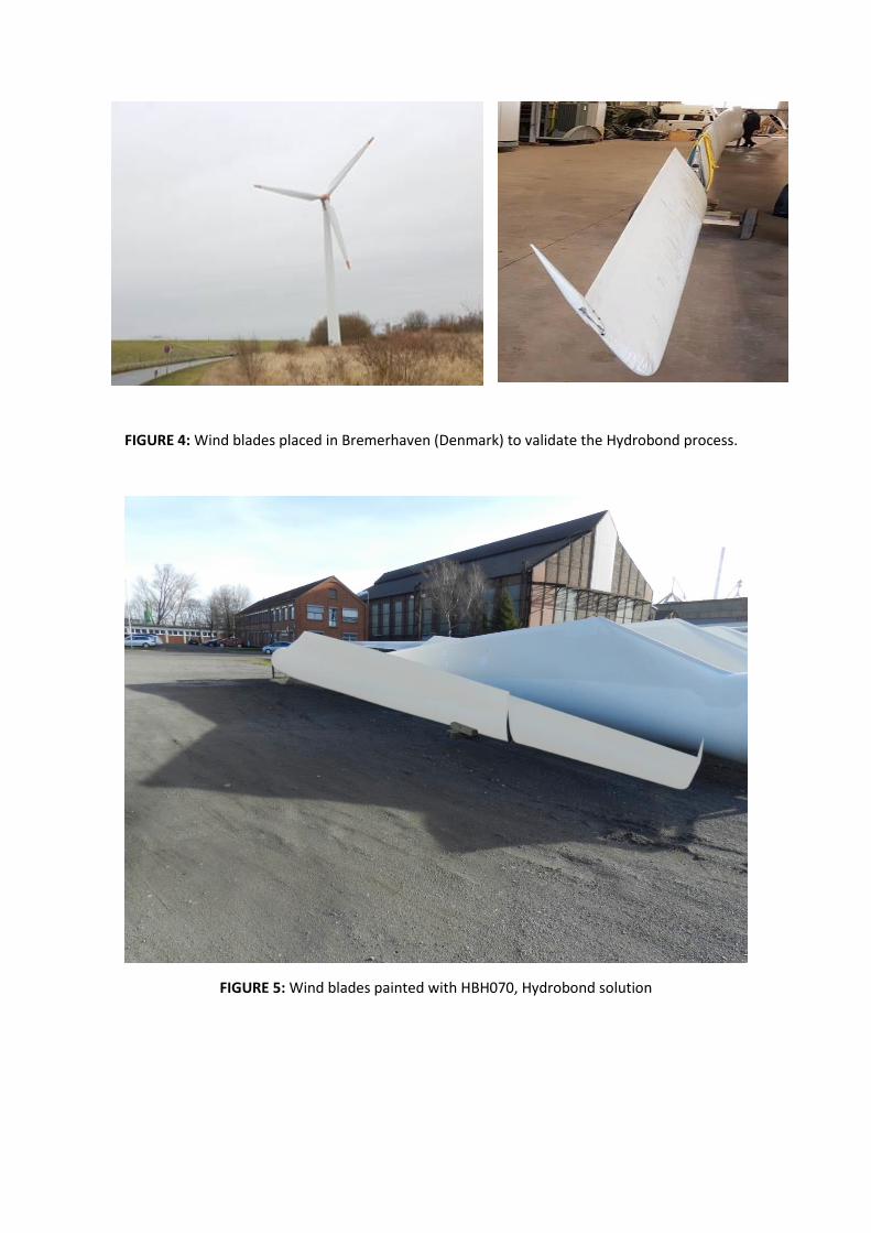
FIGURE 4: Wind blades placed in Bremerhaven (Denmark) to validate the Hydrobond process.
FIGURE 5: Wind blades painted with HBH070, Hydrobond solution
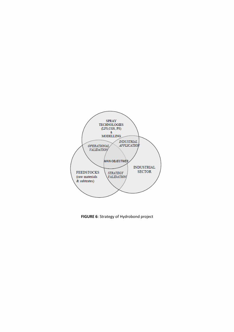
FIGURE 6: Strategy of Hydrobond project

FIGURE 7: Microstructure of composite substrate
FIGURE 8: Modelling at the microscale level of the thermomechanical properties of the
blade/coating system
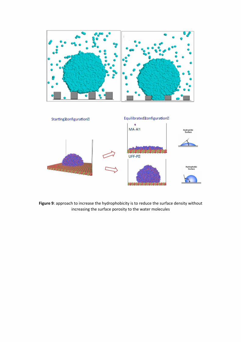
Figure 9: approach to increase the hydrophobicity is to reduce the surface density without
increasing the surface porosity to the water molecules
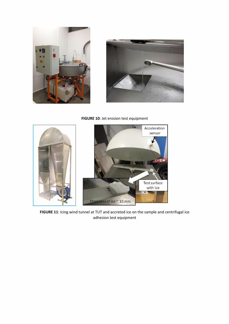
FIGURE 10: Jet erosion test equipment
FIGURE 11: Icing wind tunnel at TUT and accreted ice on the sample and centrifugal ice
adhesion test equipment
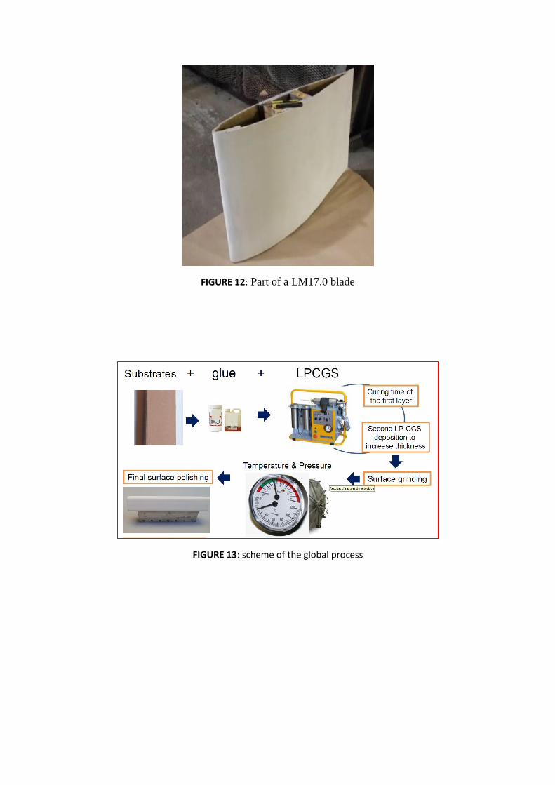
FIGURE 12: Part of a LM17.0 blade
FIGURE 13: scheme of the global process
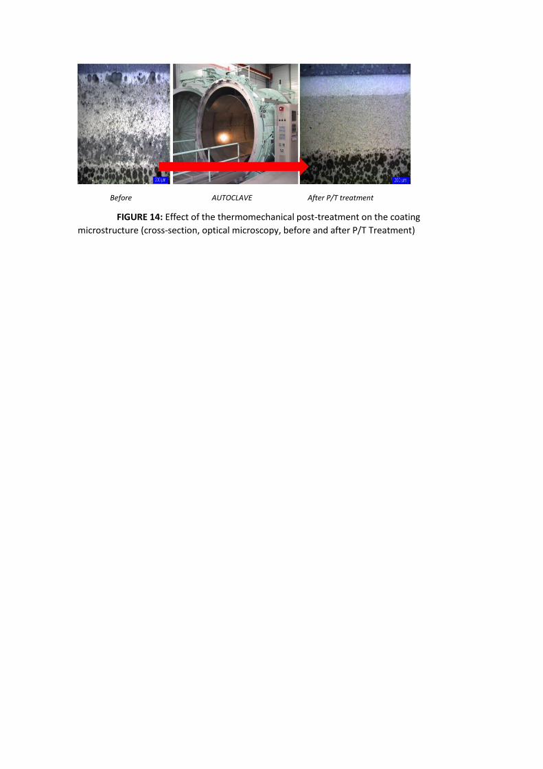
Before AUTOCLAVE After P/T treatment
FIGURE 14: Effect of the thermomechanical post-treatment on the coating
microstructure (cross-section, optical microscopy, before and after P/T Treatment)
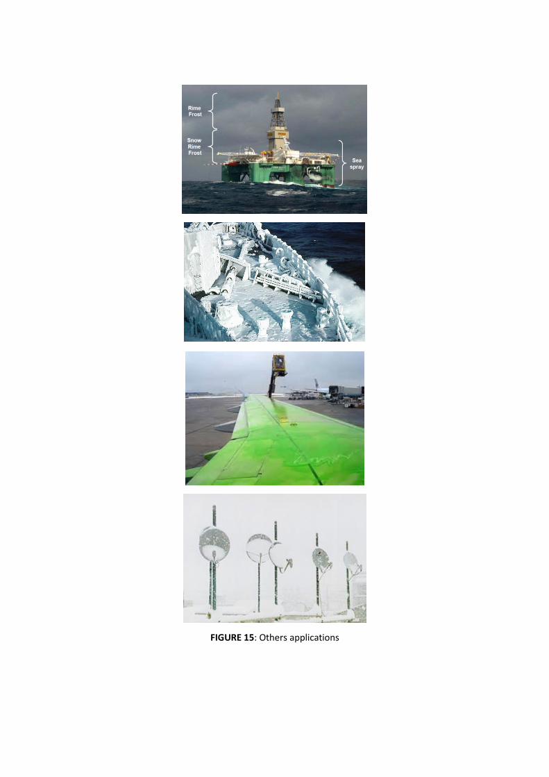
FIGURE 15: Others applications


FIGURE 17: Publicity of International workshop
FIGURE 18: Session in the International workshop
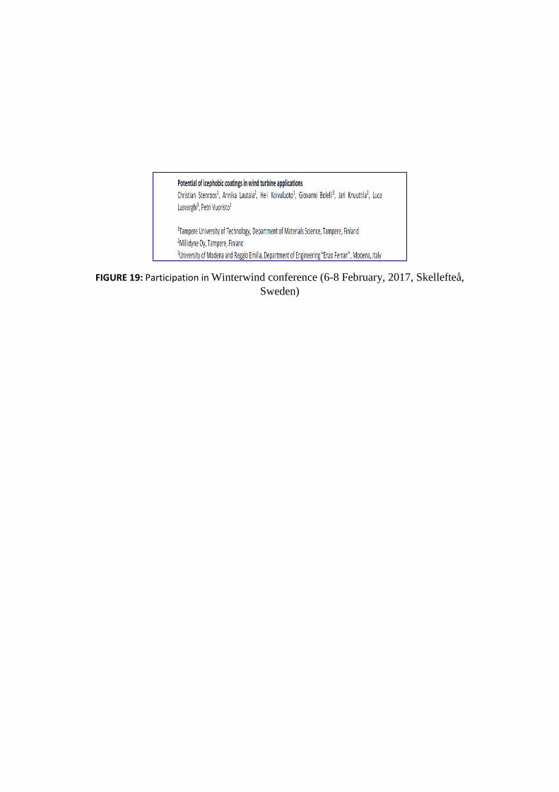
FIGURE 19: Participation in Winterwind conference (6-8 February, 2017, Skellefteå,
Sweden)

FIGURE 20: participation in International Workshop on Atmospheric Icing Structures
(28June-3July, Uppsala, Sweden, 2015)

TABLE II: tests prior the RE test:
Test method Standard Acceptance value # of replicates
Pull-off test ISO 4624 >5MPa 3
Repairability (pull-off test
after recoat) ISO 4624 >5MPa 3
Ice-adhesion <80KPa 3
Thickness reduction1 >30% 1 1Only applicable for CGS samples


