
Final Construction Plan Report –
Belle River Wind Project

Prepared by:
AECOM
105 Commerce Valley Drive West, Floor 7 905 886 7022 tel
Markham, ON, Canada L3T 7W3 905 886 9494 fax
www.aecom.com
Project Number:
60321891
Date:
May, 2015
Final Construction Plan Report – Belle River Wind Project

Final Construction Plan Report – Belle River Wind Project
Rpt_2015-05-29_Final Construction Report_60321891
Table of Contents
page
1. Introduction ..................................................................................................................................... 1
1.1 Summary of Construction Plan Report Requirements ........................................................................ 1 1.2 The Proponent ..................................................................................................................................... 2 1.3 Project Location ................................................................................................................................... 2 1.4 Summary of Key Project Information ................................................................................................... 5
2. Summary of Project Components ................................................................................................. 6
2.1 Disturbance Areas ............................................................................................................................... 8
3. Description of Construction and Installation Activities ............................................................ 13
3.1 Timing of Construction and Installation Activities .............................................................................. 13 3.2 Pre-construction Activities ................................................................................................................. 14
3.2.1 Surveying and Geotechnical Sampling Activities ................................................................. 14 3.3 Construction Activities ....................................................................................................................... 14
3.3.1 Site Preparation and Land Clearing ..................................................................................... 14 3.3.2 Construction of Access Roads ............................................................................................. 14 3.3.3 Construction of Turbine Laydown Areas .............................................................................. 15 3.3.4 Construction of Crane Pads ................................................................................................. 16 3.3.5 Construction of Wind Turbine Foundations .......................................................................... 16 3.3.6 Delivery of Equipment .......................................................................................................... 16 3.3.7 Construction Staging Areas .................................................................................................. 17 3.3.8 Wind Turbine Assembly and Installation .............................................................................. 17 3.3.9 Construction of the Electrical Collector System ................................................................... 17
3.3.9.1 Pad-Mounted Transformers ............................................................................... 18 3.3.9.2 Collector Lines .................................................................................................... 18 3.3.9.3 Horizontal Directional Drilling ............................................................................. 18
3.3.10 Construction of the Collector Substation .............................................................................. 19 3.3.11 Installation of the Transmission Line .................................................................................... 19 3.3.12 Construction of the Operations and Maintenance Building .................................................. 20 3.3.13 Construction of Permanent Meteorological Towers ............................................................. 20 3.3.14 Site Clean-up and Reclamation ............................................................................................ 20
3.4 Turbine Commissioning ..................................................................................................................... 20 3.5 Temporary Uses of Land ................................................................................................................... 21 3.6 Temporary Water Takings ................................................................................................................. 21 3.7 Materials / Waste Generation and Transportation ............................................................................. 22 3.8 Air Emissions ..................................................................................................................................... 22 3.9 Emergency Action Plan ..................................................................................................................... 23 3.10 Health and Safety Plan ...................................................................................................................... 23
4. Description of Environmental Effects and Mitigation Measures .............................................. 24
4.1 Impacts on Cultural Heritage (Archaeological and Heritage Resources, Protected Properties) ....... 24 4.2 Impacts on Vegetation and Natural Heritage (Including from Spills) ................................................. 27 4.3 Impacts to Water Resources (Including from Spills) ......................................................................... 40
4.3.1 Surface Water and Runoff and Impacts to Water Bodies ..................................................... 40 4.3.2 Impacts to Groundwater (including impacts related to Water Taking) ................................. 43

Final Construction Plan Report – Belle River Wind Project
Rpt_2015-05-29_Final Construction Report_60321891
4.3.2.1 Existing Conditions ............................................................................................. 43 4.4 Air, Odour and Dust Emissions ......................................................................................................... 44 4.5 Noise Emissions ................................................................................................................................ 44 4.6 Impacts on Land Use and Infrastructure ........................................................................................... 47
5. Summary and Conclusions .......................................................................................................... 49
6. References ..................................................................................................................................... 50
List of Figures
Figure 1-1: Project Study Area ................................................................................................................................. 3
Figure 1-2: Study Area in Ontario ............................................................................................................................. 4
Figure 2-1: Project Location ...................................................................................................................................... 9
Figure 2-2: Project Location and Natural Heritage Features .................................................................................. 10
Figure 2-3a: Project Location and Socio-economic Features .................................................................................. 11
Figure 2-3b: Project Location and Socio-economic Features .................................................................................. 12
List of Tables
Table 1-1: Adherence to Construction Plan Report Requirements under O. Reg. 359/09, as Amended ............... 1
Table 1-2: Summary of Key Project Information ..................................................................................................... 5
Table 2-1: Description of Project Components ........................................................................................................ 6
Table 2-2: Description of Temporary Project Components ..................................................................................... 7
Table 3-1: Construction Schedule ......................................................................................................................... 13
Table 3-2: Description of Access Road Dimensions and Materials Required for Construction ............................ 15
Table 4-1: Mitigation Measures, Net Effects and Monitoring Plan: Archaeological Resources and Cultural
Heritage ................................................................................................................................................ 26
Table 4-2: Summary of Natural Features Carried Forward to the Environmental Impact Study .......................... 27
Table 4-3: Mitigation Measures and Net Effects: Generalized Candidate Significant Wildlife Habitat and
Natural Heritage Features .................................................................................................................... 29
Table 4-4: Mitigation Measures, Net Effects and Monitoring Plan: Significant and Treated as Significant
Wetlands, Woodlands and Wildlife Habitat .......................................................................................... 30
Table 4-5: Mitigation Measures, Net Effects and Monitoring Plan: Surface Water ............................................... 41
Table 4-6: Summary of MOECC Water Well Record Information ......................................................................... 43
Table 4-7: Mitigation Measures, Net Effects and Monitoring Plan: Groundwater ................................................. 45
Table 4-8: Mitigation Measures, Net Effects and Monitoring Plan: Air, Odour and Dust ...................................... 46
Table 4-9: Mitigation Measures, Net Effects and Monitoring Plan: Noise ............................................................. 46
Table 4-10: Mitigation Measures, Net Effects and Monitoring Plan: Land Use and Infrastructure ......................... 48

Final Construction Plan Report – Belle River Wind Project
Rpt_2015-05-29_Final Construction Report_60321891
Acronyms and Abbreviations
ANSI ........................................... Area of Natural and Scientific Interest
Belle River Wind ........................ SP Belle River Wind LP
BMPs ......................................... Best management practices
dbh ............................................. Diameter at breast height
EEMP ......................................... Environmental Effects Monitoring Plan
EIS ............................................. Environmental Impact Study
ERCA ......................................... Essex Region Conservation Authority
GHGs ......................................... Greenhouse gases
Hydro One .................................. Hydro One Networks Inc.
IESO .......................................... Independent Electricity System Operator
km .............................................. Kilometres
kV ............................................... Kilovolts
L/day .......................................... Litres per day
m ................................................ Metres
m2 ............................................... Metres squared
m3 ............................................... Metres cubed
mm ............................................. Millimetres
m/s ............................................. Metre per second
MNRF ......................................... Ontario Ministry of Natural Resources and Forestry
MOECC ...................................... Ontario Ministry of the Environment and Climate Change
MTCS ......................................... Ontario Ministry of Tourism, Culture and Sport
MW ............................................. Megawatts
NRSI .......................................... Natural Resource Solutions Inc.
O. Reg. ....................................... Ontario Regulation
OEB ........................................... Ontario Energy Board
Pattern Development ................. Pattern Renewable Holdings Canada ULC
PDR ........................................... Project Description Report
Project ........................................ Belle River Wind Project
PSA ............................................ Project Study Area
PTTW ......................................... Permit to Take Water
REA ............................................ Renewable Energy Approval
Samsung Renewable Energy .... Samsung Renewable Energy Inc.
SCADA ....................................... Supervisory Control and Data Acquisition
SRP ............................................ Spill Response Plan
SWH ........................................... Significant Wildlife Habitat
TSS ............................................ Total Suspended Solids
ZOI ............................................. Zone of influence

Final Construction Plan Report – Belle River Wind Project
Rpt_2015-05-29_Final Construction Report_60321891 1
1. Introduction
The Belle River Wind Project (“Project”) is being proposed by SP Belle River Wind LP, by its general partner, SP
Belle River Wind GP Inc. (“Belle River Wind”). Belle River Wind is a joint venture limited partnership owned by
affiliates of Pattern Renewable Holdings Canada ULC (“Pattern Development”) and Samsung Renewable Energy
Inc. (“Samsung Renewable Energy”).
This Construction Plan Report was prepared in accordance with the requirements of the Renewable Energy
Approval (“REA”) process outlined in Ontario Regulation (“O. Reg.”) 359/09, as amended, and the Technical Guide
to Renewable Energy Approvals (Ontario Ministry of the Environment and Climate Change (“MOECC”), 2013).
The following sections provide information on the construction and installation activities, potential negative environmental
effects of construction and installation activities and mitigation measures for the identified negative effects.
1.1 Summary of Construction Plan Report Requirements
The requirements for the Construction Plan Report as defined under O. Reg. 359/09, as amended, and where those
requirements are addressed in this report are provided in the following table (Table 1-1).
Table 1-1: Adherence to Construction Plan Report Requirements
under O. Reg. 359/09, as Amended
Requirement Completed Corresponding Section
Details of construction or installation activities Yes Section 3
The location and timing of any construction or
installation activities for the duration of the
construction or installation
Yes Figure 2-1 and Section 3.1
Any negative environmental effects that may
result from construction or installation
activities
Yes Section 4
Mitigation measures in respect of any negative
environmental effects
Yes Section 4 and the Environmental
Effects Monitoring Plan (“EEMP”) in
the Design and Operations Report
This Construction Plan Report was provided to the Town of Lakeshore and County of Essex 90 days in advance of
the second public meeting. First Nation and Aboriginal Communities, government agencies and the public were able
to review copies of the report 60 days in advance of the second public meeting. These timelines align with the
distribution requirements outlined in O. Reg. 359/09, as amended, and the Technical Guide to Renewable Energy
Approvals (MOECC, 2013).

Final Construction Plan Report – Belle River Wind Project
Rpt_2015-05-29_Final Construction Report_60321891 2
1.2 The Proponent
Applicant:
As noted above, Belle River Wind is a joint venture limited partnership owned by affiliates of Pattern Development
and Samsung Renewable Energy. The contacts for the Project are as follows:
Brian Edwards
Project Developer
Samsung Renewable Energy
2050 Derry Road West, 2nd floor
Mississauga, ON L5N 0B9
Phone: (905) 501-5667
Email: [email protected]
Jody Law
Project Developer
Pattern Development
355 Adelaide Street West, Suite 100
Toronto, ON M5V 1S2
Phone: (416) 263-8026
Email: [email protected]
Consultant:
Marc Rose
Senior Environmental Planner
AECOM
105 Commerce Valley Drive West, 7th Floor
Markham, ON L3T 7W3
Phone: (905) 747-7793
Email: [email protected]
Project:
Project Email: [email protected]
Project Website: www.belleriverwind.com
1.3 Project Location
Belle River Wind is proposing to develop a wind project in the Town of Lakeshore in the County of Essex, Ontario.
The Project will be located on public and private lands south of the community of Belle River. The location of the
Project was established based on interest expressed by local landowners, the availability of wind resources, and
availability of existing infrastructure for connection to the electrical grid.
According to O. Reg. 359/09, as amended, the Project Location is “a part of land and all or part of any building or
structure in, on, or over which a person is engaging in or proposes to engage in the project and any air space in which
a person is engaging in or proposes to engage in the project”. As described therein, the Project Location boundary is
the outer limit of where site preparation and construction activities will occur (i.e., disturbance areas described below)
and where permanent infrastructure will be located, including the air space occupied by turbine blades.
The Project is generally bounded by County Road 42 to the north, Lakeshore Road 111 to the west, Highway 401
and South Middle Road to the south, and Comber Sideroad to the east. The area encompassed by these boundaries
is referred to as the Project Study Area (“PSA”). Figure 1-1, below, shows a map of the PSA. To see the location of
the Project within Ontario, please see Figure 1-2.

Final Construction Plan Report – Belle River Wind Project
Rpt_2015-05-29_Final Construction Report_60321891 3
Figure 1-1: Project Study Area
The PSA covers approximately 22,200 acres1 of land that the Town of Lakeshore’s Official Plan (2010) and the
Town of Lakeshore Zoning By-law (2014) identify as predominantly agricultural in use. The PSA also consists of
fragmented areas of forest and riparian habitat associated with small creeks or farm drains. The Project is not
situated on Crown land or within areas protected under provincial land use plans. The PSA represents the area
being assessed as part of the REA process. The following co-ordinates define corners of the external boundaries of
the PSA:
Longitude Latitude
-82.769 42.277
-82.687 42.236
-82.645 42.2
-82.55 42.268
1. Metric units are used throughout REA documentation when describing the size of Project infrastructure, except in instances describing areas of land. When describing land size, acres (imperial) will be used rather than hectares (metric) because it is the measuring unit most commonly used by the local community. It is assumed that 1 hectare of land is equal to 2.47 acres of land.

Final Construction Plan Report – Belle River Wind Project
Rpt_2015-05-29_Final Construction Report_60321891 4
Figure 1-2: Study Area in Ontario

Final Construction Plan Report – Belle River Wind Project
Rpt_2015-05-29_Final Construction Report_60321891 5
1.4 Summary of Key Project Information
A summary of key Project information is presented in the table below.
Table 1-2: Summary of Key Project Information2
General Project Name: Belle River Wind Project
Project Ownership and Operation: SP Belle River Wind LP
Project Lifespan (commercial operation): 20 Years
Project Nameplate Capacity: Up to 100 megawatts (“MW”)
Project Area
(as shown in Figure 1-1)
Location of Project: Privately-owned land and public road allowances in
the Town of Lakeshore, County of Essex
Total Project Study Area: 22,200 acres
Total Area of Project Location (total disturbance area): 1,760 acres
Wind Turbine
Generators
Make and Model: Siemens SWT-3.2-113
Total Number Permitted: 49 turbines
Approximate Number Constructed: 44 turbines
Nominal Turbine Power: 2.257 to 3.2 MW
Number of Blades: 3
Blade Length: 55 metres (“m”)
Hub Height: 99.5 m
Rotor Diameter: 113 m
Cut-in Wind Speed: 3 to 5 metres per second (“m/s”)
Cut-out Wind Speed: 32 m/s
Rated Wind Speed: 12 to 13 m/s
Swept Area: 10,000 metres squared (“m2”)
Foundation Dimensions: 25 m diameter
Access Roads Access Roads – Operations:
(includes shoulder, travel width and ditch)
49 kilometres (“km”) x 8 to 12 m
Access Roads – Construction (with shoulder): 49 km x 8 to 15 m
Collector Lines 34.5 kilovolts (“kV”) Collector Lines in Public Right-of-way:
(total combined length of proposed underground and/or overhead)
80 km x 2 to 6 m
34.5 kV Collector Lines on Private Lands (underground): 49 km x 2 to 6 m
Transmission Line 230 kV Transmission Line in Public Right-of-way or
Private Lands
5 to 10 km x 2 to 6 m
Other Project Structures
and Facilities
Collector Substation: 10 acres
Operations and Maintenance Building: 7 acres
Interconnection Station: 10 acres
Meteorological Towers: Up to 2
Microwave Tower: Up to 2
Temporary Land Use
(Construction Phase)
Construction Staging Areas: 10 to 15 acres
Wind Turbine Laydown Area (each turbine): 1.5 acres
Crane Pads: 0.2 acres
2. Dimensions are near approximations.
Final Construction Plan Report – Belle River Wind Project
Rpt_2015-05-29_Final Construction Report_60321891 6
2. Summary of Project Components
The proposed Project Location is shown on Figure 2-1 and includes the components of the Project listed in
Table 2-1 below.
A description and listing of Project components and temporary Project components are outlined below in Table 2-1
and Table 2-2, respectively.
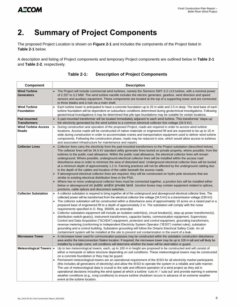
Table 2-1: Description of Project Components
Component Description
Wind Turbine
Generators
The Project will include commercial wind turbines, namely the Siemens SWT-3.2-113 turbine, with a nominal power
of 2.257 to 3.2 MW. The wind turbine nacelle includes the electric generator, gearbox, wind direction and speed
sensors and auxiliary equipment. These components are located at the top of a supporting tower and are connected
to three blades and a hub via a main shaft.
Wind Turbine
Foundation
Each turbine tower is anticipated to have a concrete foundation up to 25 m wide and 2.5 m deep. The land base of each
turbine foundation will be dependent on subsurface conditions determined during geotechnical investigations. Following
geotechnical investigations it may be determined that pile type foundations may be suitable for certain locations.
Pad-mounted
Transformers
A pad-mounted transformer will be located immediately adjacent to each wind turbine. This transformer ‘steps-up’
the electricity generated by the wind turbine to a common electrical collector line voltage (34.5 kV).
Wind Turbine Access
Roads
During construction and operation of the proposed Project, roads are required in order to access wind turbine
locations. Access roads will be constructed of native materials or engineered fill and are expected to be up to 15 m
wide during construction in order to accommodate cranes and transportation equipment used to deliver wind turbine
components. Following the construction phase, roads may be reduced in size, which would allow access to turbines
and associated infrastructure for maintenance and repairs.
Collector Lines Collector lines carry the electricity from the pad-mounted transformers to the Project substation (described below).
The collector lines will be 34.5 kV standard utility generator lines buried on private property, where possible, from the
turbines to the public road allowance. Within the public road allowance, the electrical collector lines will remain
underground. Where possible, underground electrical collector lines will be installed within the access road
disturbance area in order to minimize the area of disturbed land. Underground electrical collector lines will be buried
at a minimum depth of approximately 1.2 m. Farming practices will not be affected by the underground cabling due
to the depth of the cables and location of the cable beneath the access roads.
If aboveground electrical collector lines are required, they will be constructed on hydro pole structures that are
similar to existing electrical distribution lines in the PSA.
Where two or more underground collector lines must be connected together, a junction box will be installed either
below or aboveground on public and/or private land. Junction boxes may contain equipment related to splices,
junctions, cable splices and disconnect switches.
Collector Substation A collector substation is required to bring together all of the underground and aboveground electrical collector lines. The
collected power will be transformed from the electrical collector line voltage (34.5 kV) to a transmission voltage (230 kV).
The collector substation will be constructed within a disturbance area of approximately 10 acres on a raised pad or a
prepared base of engineered fill to a depth of approximately 2 m. The substation will comply with the noise
requirements specified in O. Reg. 359/09, as amended.
Collector substation equipment will include an isolation switch(es), circuit breaker(s), step-up power transformer(s),
distribution switch-gear(s), instrument transformers, capacitor banks, communication equipment, Supervisory
Control and Data Acquisition (“SCADA”) equipment, protection and control equipment, grounding transformers,
revenue metering (conforming to Independent Electricity System Operator (“IESO”) market rules), substation
grounding and a control building. Substation grounding will follow the Ontario Electrical Safety Code. An oil
containment system will be installed at the site to prevent soil contamination in the event of a leak.
Microwave Tower A microwave tower used for communication purposes may be constructed within the substation construction disturbance
area and/or the Interconnection Station location. If required, the microwave tower may be up to 100 m tall and will likely be
installed by a single crane; soil conditions will determine whether the tower will be steel-lattice or guyed.
Meteorological Towers Up to two meteorological towers, each, up to 100 m in height are proposed to be constructed and will consist of
either a monopole or lattice structure depending on soil conditions. These meteorological towers may be constructed
on a concrete foundation or they may be guyed.
Permanent meteorological towers are an operational requirement of the IESO for all electricity market participants
(this includes all generators of electricity) and allow the IESO to operate the system in a reliable and safe manner.
The use of meteorological data is crucial to the safe and efficient operation of a wind project as they aid in
operational decisions including the wind speed at which a turbine ‘cuts-in’ / ‘cuts-out’ and provide warning in extreme
weather conditions (e.g., icing conditions) to ensure turbine shutdown occurs in advance of an extreme weather
event at the turbine location.

Final Construction Plan Report – Belle River Wind Project
Rpt_2015-05-29_Final Construction Report_60321891 7
Table 2-1: Description of Project Components
Component Description
Transmission Line and
Interconnection
Station (Connection to
Electrical Grid)
A 230 kV electrical transmission line will be built from the transformer substation to a connection point on the Hydro
One Networks Inc. (“Hydro One”) transmission corridor. The transmission line will be buried and/or mounted on new
poles or a combination thereof. The poles will be made of wood, concrete or steel. The line will be located on private
property and/or within existing municipal road right-of-ways. The point of interconnection will require modifications to
the existing transmission line and may include circuit breakers, isolation switches, transmission switchgear,
instrumentation, grounding, metering equipment and other equipment typical of such systems.
The interconnection plan for any wind project is subject to study, design and engineering by the IESO which
manages the province’s electricity grid, Hydro One which owns the transmission lines, the local hydro distribution
company and the Ontario Energy Board (“OEB”), which regulates the industry through the Transmission System
Code and the Distribution System Code.
Operations and
Maintenance Building
An operations and maintenance building will be constructed to accommodate offices, mess facilities, control
facilities, storage space, maintenance work area and a parking area. It will be located within the same disturbance
area as either the collector substation or interconnection station.
The operations and maintenance building will be constructed on a concrete foundation. An access road to the
operations and maintenance building from a municipal road will be constructed to accommodate construction
equipment and on-site traffic during the operation of the Project.
The operations and maintenance building will be powered by the local distribution company, with an on-site backup
power supply. The power will be delivered via overhead poles installed adjacent to the access road and will
terminate on a transformer pole adjacent to the operations and maintenance building. An underground cable will
then connect the transformer pole to the building electrical service.
To facilitate the construction of the proposed Project, a number of temporary construction components are required.
These temporary components, described further in Table 2-2 below, include crane pads, turbine laydown areas and
a construction staging area.
Table 2-2: Description of Temporary Project Components
Component Description
Crane Pads Crane pads will be constructed in tandem with wind turbine access roads. Crane pads will be located directly
adjacent to wind turbine locations and within the associated construction disturbance area. The crane pad area will
be approximately 0.2 acres, and will consist of a mixture of heavier granular material, native materials and
engineered fill, as appropriate.
Crane pad areas will be restored following construction so that existing land uses can continue. As required for
maintenance and decommissioning activities, crane pads may be reconstructed in the future.
Wind Turbine
Laydown Areas
Laydown areas adjacent to wind turbine locations will be incorporated into the disturbance area for each turbine.
Each disturbance area is approximately 1.5 acres and will allow for temporary turbine component storage during
construction. Temporary wind turbine laydown areas will be restored following construction activities so that
agricultural activities can continue.
Construction
Staging Area
A temporary construction staging area will be located within the PSA. The construction staging area will consist of
compacted surface material suitable for vehicular traffic. The depth of the material required will vary and will be
dependent upon conditions encountered during the time of construction. The construction staging area will be
approximately 10 to 15 acres in size and will primarily serve the following aspects of the Project construction:
Construction equipment / toll storage and maintenance;
Laydown areas for Project components;
Location of Project construction offices;
Parking areas for Project staff;
Portable generators;
Waste disposal containers;
Self-contained temporary toilet facilities; and
Water and rinsing facilities.
Following Project construction, the temporary construction staging area will be restored to pre-existing conditions so
that previous land use can continue. Construction offices and temporary storage of Project equipment may also
occur in pre-existing areas used for commercial and industrial purposes.

Final Construction Plan Report – Belle River Wind Project
Rpt_2015-05-29_Final Construction Report_60321891 8
2.1 Disturbance Areas
Disturbance Areas have been identified surrounding various Project components, which are depicted on Figure 2-1
as the “Project Location”. The Project Location denotes the location of wind turbines, access roads, the electrical
collector system, 230 kV transmission line route options, collector substation options and temporary laydown /
storage areas. The figure also outlines areas where temporary disturbance may occur as a result of construction of
Project component laydown and storage areas, crane pad construction, turnaround areas, and access roads and
electrical collector system. With the exception of the Project components described above, no permanent
infrastructure is proposed within these areas. Following construction activities, the land will be returned to pre-
existing land uses, unless otherwise agreed to with landowners.
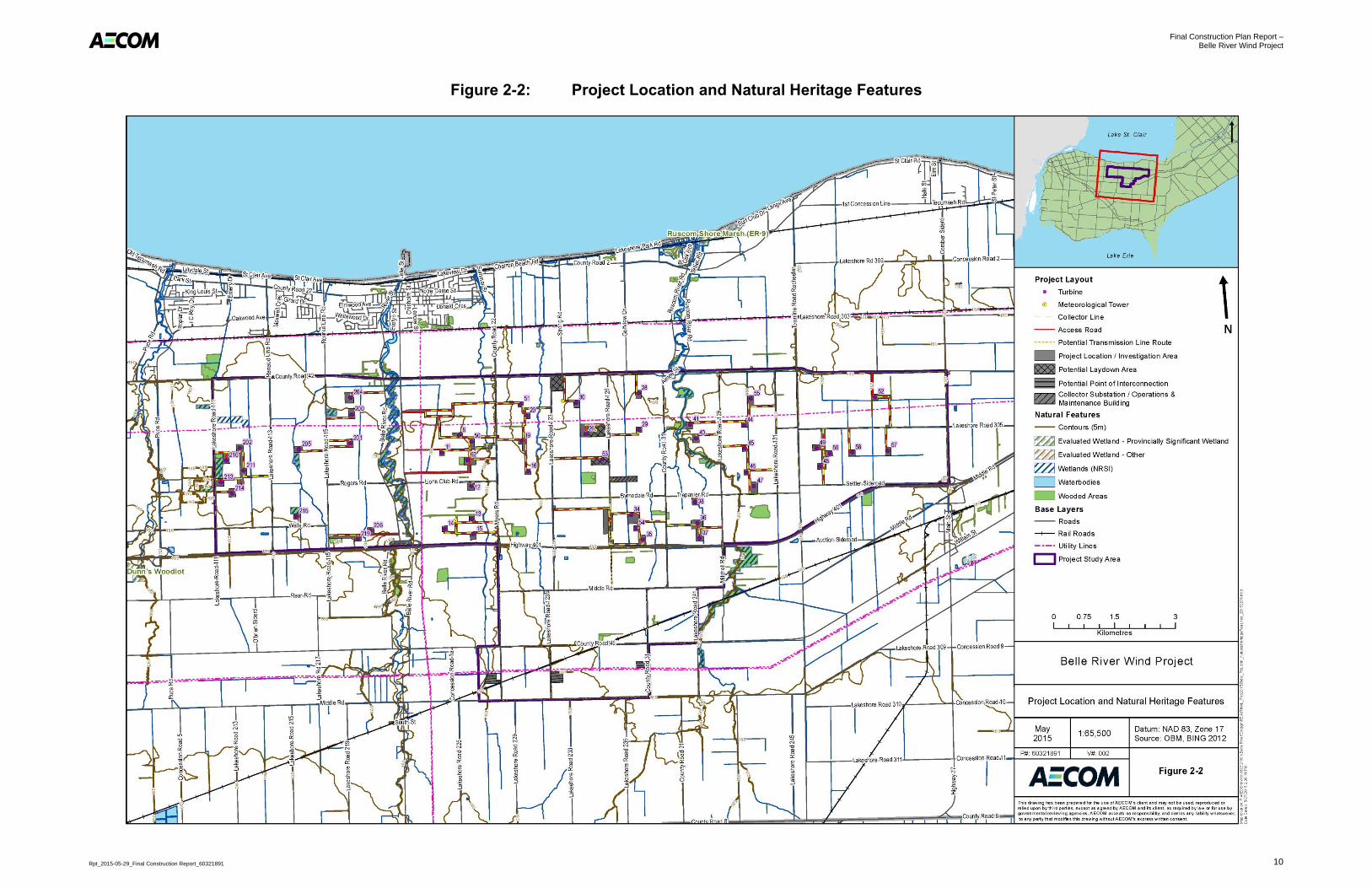
In addition to Figure 2-1 which depicts the Project Location, the following figures also provide visual illustration of
the following:
Figure 2-2: Location of Project components and associated disturbance areas in relation to surrounding
natural heritage and water body features such as: wetlands, woodlands, and streams, in addition to water
wells identified in the MOECC’s database. This figure also illustrates compliance with the 120 m setback
distance for natural heritage features, measured from the boundary of the Project Location, as well as
topographical land contours and surface water drainage for all lands within 120 m of the Project Location.
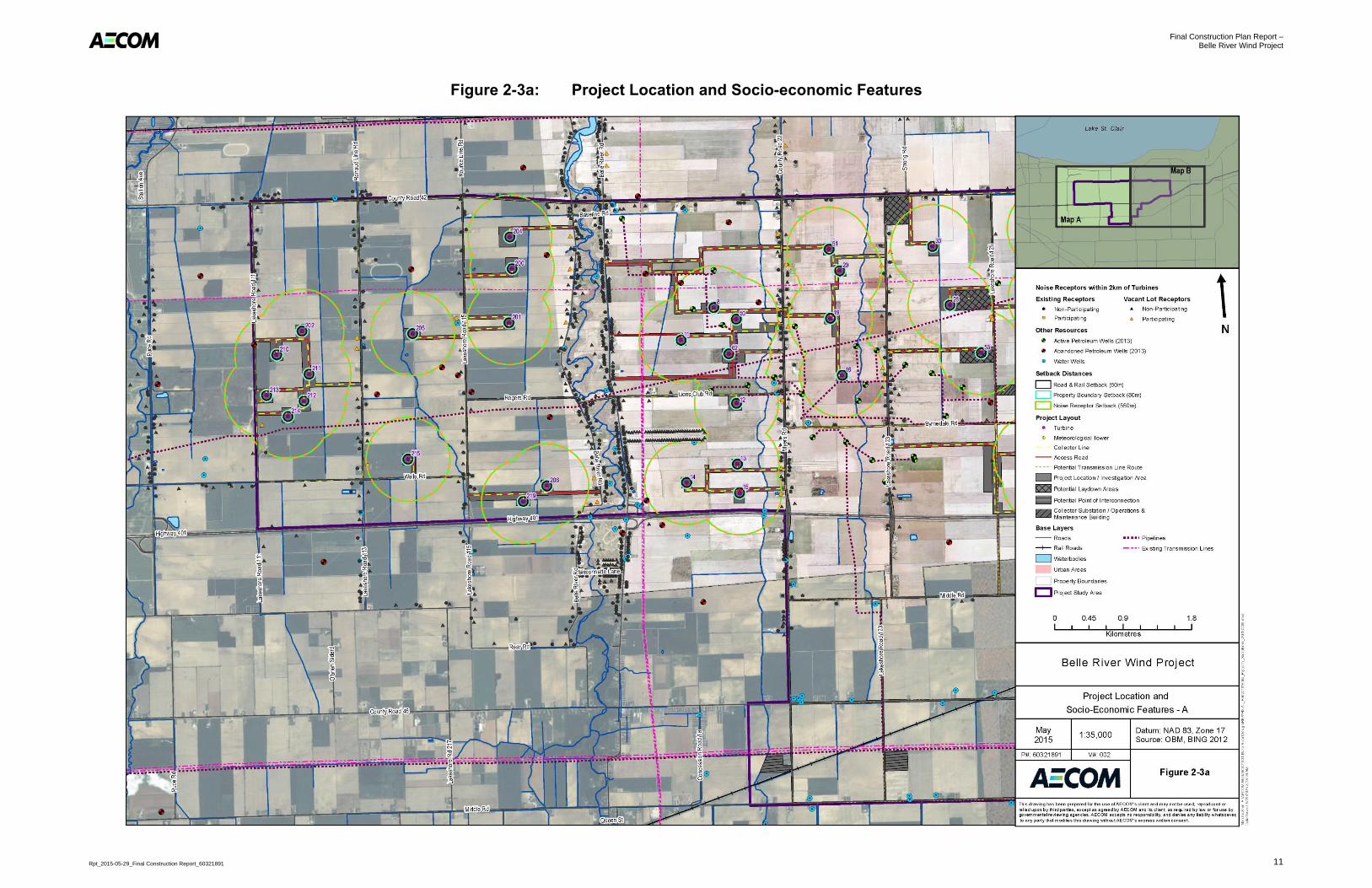
Figure 2-3a and Figure 2-3b: Location of Project components and associated disturbance areas in
relation to surrounding socio-economic features such as: property boundaries, roads and railways,
petroleum resources, landfills, aggregate resources and noise receptors. This figure also identifies the
setback distances between these features and the Project components. Note that noise compliance is
assessed in the Noise Impact Assessment (refer to Appendix C of the Design and Operations Report).
The precise location of archaeological resources is sensitive information and is not depicted on the figures described
above to prevent these resources from being located; however, the Heritage Assessment Report and Stage 1 and 2
Archaeological Assessment Reports were submitted for review and approval by the Ontario Ministry of Tourism,
Culture and Sport (“MTCS”). The Heritage Impact Assessment for the Project concluded that no protected properties
or heritage resources are located within the PSA and, therefore, are not depicted on the figures described above.
The following sections outline the activities anticipated for the construction phase of the Project and provide details
on the timing of the activities, materials brought on site, construction equipment used and temporary uses of the
land.
Additional details regarding Project activities are provided in the following reports. These reports will form part of the
Project’s REA Application:
Project Description Report (“PDR”);
Design and Operations Report; and
Decommissioning Plan Report.

Final Construction Plan Report – Belle River Wind Project
Rpt_2015-05-29_Final Construction Report_60321891 9
Figure 2-1: Project Location
Final Construction Plan Report – Belle River Wind Project
Rpt_2015-05-29_Final Construction Report_60321891 10
Figure 2-2: Project Location and Natural Heritage Features
Final Construction Plan Report – Belle River Wind Project
Rpt_2015-05-29_Final Construction Report_60321891 11
Figure 2-3a: Project Location and Socio-economic Features

Final Construction Plan Report – Belle River Wind Project
Rpt_2015-05-29_Final Construction Report_60321891 12
Figure 2-3b: Project Location and Socio-economic Features

Final Construction Plan Report – Belle River Wind Project
Rpt_2015-05-29_Final Construction Report_60321891 13
3. Description of Construction and Installation Activities
The following sections provide the following information for construction and installation activities:
Project timing;
Materials brought on-site;
Construction equipment used; and
Explanation of how the components will be constructed.
In general, all work crews will drive automobiles (typically light trucks) to reach the PSA. Flatbed trucks will be used
to transport specialized equipment (e.g., tracked bulldozers, excavators, loaders, dump trucks, compactors and
graders) to the PSA. Construction equipment, fuel and lubricants will be delivered to temporary storage / laydown
areas by large truck and trailer combinations.
3.1 Timing of Construction and Installation Activities
Subject to the receipt of the necessary permits and approvals, site work for the Belle River Wind Project is expected
to begin in 2016 and last for approximately 12 months. Construction and installation activities will generally occur at
times of day when agricultural machinery would normally be in operation, unless circumstances require otherwise.
Table 3-1 presents the anticipated construction schedule and approximate order of construction activities for the
proposed Project.
Table 3-1: Construction Schedule
Activity Estimated Start Date Estimated Duration
Surveying “Prior to Construction”
Spring / Summer 2015 2 to 3 months
Geotechnical Sampling “Prior to Construction”
Spring / Summer 2015 3 to 4 months
Site Preparations and Land Clearing Summer / Fall 2016 2 to 3 months
Access Road Construction Summer / Fall 2016 5 to 6 months
Construction of Laydown Area Summer / Fall 2016 6 months
Turbine Site and Crane Pad Construction Summer / Fall 2016 6 months
Turbine Foundations Construction Summer / Fall 2016 8 months
Collector Substation Construction Summer / Fall 2016 12 months
Transmission Line and Interconnection Station Construction Summer / Fall 2016 12 months
Delivery of Equipment Fall / Winter 2016 As needed throughout construction phase
Wind Turbine Assembly and Installation Fall / Winter 2016 8 months
Electrical Collector
System Construction
Pad-Mounted Transformers Fall / Winter 2016 8 months
Collector Lines Fall / Winter 2016 8 months
Operations and Maintenance Building Construction Fall / Winter 2016 8 months
Meteorological Towers and Microwave Tower Installation Fall / Winter 2016 6 month
Turbine Testing and Commissioning Summer 2017 4 months
Clean-up and Site Reclamation Summer / Fall 2017 3 months
Final Construction Plan Report – Belle River Wind Project
Rpt_2015-05-29_Final Construction Report_60321891 14
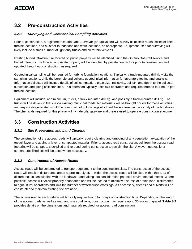
3.2 Pre-construction Activities
3.2.1 Surveying and Geotechnical Sampling Activities
Prior to construction, a registered Ontario Land Surveyor (or equivalent) will survey all access roads, collector lines,
turbine locations, and all other foundations and work locations, as appropriate. Equipment used for surveying will
likely include a small number of light duty trucks and all-terrain vehicles.
Existing buried infrastructure located on public property will be identified using the Ontario One Call service and
buried infrastructure located on private property will be identified by private contractors prior to construction and
updated throughout construction, as required.
Geotechnical sampling will be required for turbine foundation locations. Typically, a truck-mounted drill rig visits the
sampling locations, drills the borehole and collects geotechnical information for laboratory testing and analysis.
Information collected will include details of soil compaction, grain size, resistivity, soil pH, and depth to the collector
substation and along collector lines. This operation typically uses two operators and requires three to four hours per
turbine location.
Equipment will include, at a minimum, trucks, a truck mounted drill rig, and possibly a track-mounted drill rig. The
trucks will be driven to the site via existing municipal roads. No materials will be brought on-site for these activities
and any waste generated would be comprised of drill cuttings which will be scattered in the vicinity of the boreholes.
The chemicals required for this phase will include oils, gasoline and grease used to operate construction equipment.
3.3 Construction Activities
3.3.1 Site Preparation and Land Clearing
The construction of the access roads will typically require clearing and grubbing of any vegetation, excavation of the
topsoil layer and adding a layer of compacted material. Prior to access road construction, soil from the access road
footprint will be stripped, stockpiled and re-used during construction to reclaim the site. A woven geotextile or
cement-stabilized soil will be used where necessary.
3.3.2 Construction of Access Roads
Access roads will be constructed to transport equipment to the construction sites. The construction of the access
roads will result in disturbance areas approximately 15 m wide. The access roads will be sited within this area of
disturbance in consultation with the landowner and taking into consideration potential environmental effects. Where
possible, access will follow property boundaries and will be located to minimize the loss of arable land, disturbance
to agricultural operations and limit the number of watercourse crossings. As necessary, ditches and culverts will be
constructed to maintain existing site drainage.
The access road to each turbine will typically require two to four days of construction time. Depending on the length
of the access roads as well as road and site conditions, construction may require up to 30 trucks of gravel. Table 3-2
provides details on the dimensions and materials required for access road construction.

Final Construction Plan Report – Belle River Wind Project
Rpt_2015-05-29_Final Construction Report_60321891 15
Table 3-2: Description of Access Road Dimensions and Materials Required for Construction
Access Road Description Measurement Estimated Quantity Required (up to)
Roadbed Depth Granular Base Material1 0.50 to 0.75 m 300,000 metres cubed (“m
3”)
Crushed Gravel2 0.10 to 0.20 m 80,000 m
3
Total 0.60 to 0.95 m 440,000 m3
Permanent Road Width3 8 to 12 m --
Road Length3 50 km --
Notes: 1. A woven geotextile or cement-stabilized soil may be utilized which would reduce the amount of granular base
material required. Approximately 50,000 m2 of geotextile material may be required for access road construction.
2. This width includes shoulder, travel width and ditch.
3. Approximate Dimensions
New culverts may be required to maintain drainage in ditches at junctions with roadways and these will be
constructed to support the construction equipment and delivery trucks. The details of culverts and their installation in
addition to erosion control measures will be determined in conjunction with the Essex Region Conservation Authority
(“ERCA”) and Town of Lakeshore as part of their permitting processes. Once the construction activities have been
completed, the width of the access roads will be reduced and the granular base of the access roads will be removed
and distributed to the landowners, if desired, or removed from the site and disposed of in an approved and
appropriate manner. The disturbed area will have the topsoil replaced from stockpiled material and will be reseeded
at the discretion of the landowner.
The construction crew is anticipated to require approximately six people and the timeline for constructing an access
road to a turbine is expected to take between two and four days to complete, depending on the length of the road
and site conditions. Equipment will include, at a minimum, trucks, graders and bulldozers. The trucks and graders
will be driven to the site and the bulldozers will be transported via trailers. The chemicals required for this phase will
include oils, gasoline and grease used to operate construction equipment. Fuel-handling will be conducted in
compliance with the mitigation measures outlined in Section 4.
3.3.3 Construction of Turbine Laydown Areas
A site of approximately 1.5 acres will be constructed for the temporary storage of construction material (i.e., no
turbine components) and as a site for the construction office trailers. Following clearing and grubbing of any
vegetation, the topsoil at the temporary laydown area will be removed and a layer of clean compacted crushed
gravel will be imported as needed. The excavated topsoil will be re-used on-site, where feasible. A temporary
electrical service line will be connected to the existing distribution line for the purpose of providing power to the
construction office trailers. Following the construction phase, the gravel will be removed from the site or re-used, at
the discretion of landowners. The temporary electrical service line and poles will be removed. The stockpiled topsoil
will then be redistributed throughout the temporary laydown area.
The construction crew is anticipated to require approximately six people and construction activities are expected to
last for approximately four to six days. Equipment will include, at a minimum, trucks, graders and bulldozers. The
trucks and graders will be driven to the site and the bulldozers will be transported via trailers. The chemicals required
for this phase will include oils, gasoline and grease used to operate construction equipment. Fuel-handling will be
conducted in compliance with the mitigation measures outlined in Section 4.

Final Construction Plan Report – Belle River Wind Project
Rpt_2015-05-29_Final Construction Report_60321891 16
3.3.4 Construction of Crane Pads
Temporary crane pads will be constructed at the same time as the access roads and will be located adjacent to the
turbine locations. Bulldozers will remove topsoil and subsoil, and crane pad locations will be filled with a varying
mixture of granular base material and crushed gravel depending on site specific conditions. Geotextile will be used
as required to meet crane bearing capacity requirements. Crane mats (large pieces of wood) will be used to stabilize
cranes during their operation. The crane pad dimensions will be approximately 0.2 acres. The excavated topsoil will
be re-used on-site as feasible. Once the turbine erection is complete, the crane pad, granular base materials and
crushed gravel will be removed, native topsoil replaced, and crane pads returned to their pre-construction condition,
at the discretion of the landowners.
The construction crew is anticipated to require approximately six people and construction activities are expected to
last for approximately two to four days. Equipment will include, at a minimum, trucks, graders and bulldozers. The
trucks and graders will be driven to the site and the bulldozers will be transported via trailers. The chemicals required
for this phase will include oils, gasoline and grease used to operate construction equipment. Fuel-handling will be
conducted in compliance with the mitigation measures outlined in Section 4.
3.3.5 Construction of Wind Turbine Foundations
A determination of a final turbine foundation design will be based on results of site-specific geotechnical
assessments. Based on site specific conditions that will be determined from geotechnical assessments, blasting may
be required during wind turbine foundation excavation. Following the assessments, it may be determined that pile
type foundations are more suitable for specific locations.
For typical foundations, the expected dimensions of the wind turbine foundation excavation are 0.2 acres with an
excavated depth of up to 3 m. Stockpiled material will have topsoil and subsoil separated out and surplus excavated
material may be removed from the site for disposal in an approved manner. The foundation will be constructed of
poured concrete and reinforced with steel rebar to provide strength. The construction timeframe for turbine
foundations is approximately four to seven days, excluding curing time.
After construction the foundation will be backfilled and the surface will be landscaped for drainage. The only surface
evidence of the foundation will be a small protrusion of concrete to which the tower is attached; as such, land can be
cultivated to within a few metres of the turbine. Any wood-waste generated will be removed from the site and
recycled unless the landowner otherwise directs. Spent welding rods will be disposed of as hazardous waste by a
licensed contractor.
Equipment required for the construction and installation of wind turbine foundations will include light-duty trucks,
tracked bulldozers, excavators, loaders, dump trucks, compactors, graders, concrete trucks, concrete pump trucks,
boom truck or crane and water trucks. An estimated 50 concrete truck loads will be required for each wind turbine
foundation. The trucks, crane and graders will be driven to the site and the bulldozers will be transported via trailers.
The chemicals required for this phase will include oils, gasoline and grease used to operate construction equipment.
Fuel-handling will be conducted in compliance with the mitigation measures outlined in Section 4.
3.3.6 Delivery of Equipment
Equipment will be delivered by truck and trailer throughout the construction phase and stored at the temporary laydown
areas surrounding each turbine. Each turbine site will include required infrastructure to accommodate delivery of
oversized loads (e.g., turbine components). A Road Use Agreement will be developed in consultation with the Town of
Lakeshore and Essex County. Alternative traffic routes will be prepared to address traffic congestion, as needed.

Final Construction Plan Report – Belle River Wind Project
Rpt_2015-05-29_Final Construction Report_60321891 17
3.3.7 Construction Staging Areas
Up to three potential temporary construction staging areas may be located within the PSA. The temporary
construction staging areas will each be approximately 10 to 15 acres.
Topsoil and subsoil will be stripped and stockpiled on-site and the construction staging areas will be constructed of
compacted surface material suitable for vehicular traffic and equipment / component storage. The depth of the
graveled areas will vary and will be dependent on conditions encountered during the time of construction. Following
Project construction, the temporary construction laydown area will be restored to pre-existing conditions to allow
agricultural or prior activities to resume, at the discretion of landowners.
Equipment required to prepare the construction staging areas will include trucks, excavators, bulldozers, graders
and compaction equipment. The construction staging areas will take approximately four to six weeks to prepare.
Fuel-handling will be conducted in compliance with the mitigation measures outlined in Section 4.
3.3.8 Wind Turbine Assembly and Installation
Turbine components will arrive on-site using flatbed and other trucks and will be temporarily stored on-site in the
immediate vicinity of the base prior to assembly. Wind turbines will be assembled on-site by qualified installers.
Typically two cranes will be used to install the turbines. The larger crane is usually a crawler type with a capacity of
600 tonnes or larger, and is used for the higher lifts.
Cranes and crew will erect the wind turbines once the foundations are completed and the concrete has cured. This will
typically be in seven to ten lifts (five for the tower sections, one for the nacelle and one to three for the rotor) over a
period of three to five days depending on environmental conditions (i.e., high wind conditions would delay installation).
The lower tower sections may be installed several days before the upper tower sections and the turbine to optimize
installation sequence. The lower tower section will also include electrical and communications equipment.
Following the erection of the wind turbine tower, the nacelle (which will be assembled prior to the delivery) will be
lifted into place by the heavy-lift crane. The wind turbine rotor, which consists of three blades and the hub, will be
lifted into place by a combination of two cranes. One smaller crane will stabilize the rotor as the larger crane does
the heavy lifting. In some circumstances, a single blade and hub lifting technique may be utilized where space or
high wind constraints prevent the rotor from being lifted in one piece. Installation may require 15 to 20 people at the
site. Upon completion, packing frames for the turbine components will be returned to the turbine vendor.
Equipment will include, at a minimum, trucks, two cranes, graders and bulldozers. The trucks and graders will be
driven to the site and the bulldozers will be transported via trailers. The larger track mounted crane can move from
turbine site to turbine site; however, it may need to be disassembled to move it along roadways and from the Project
site. Alternatively, cranes may be moved between turbine sites without disassembly along access roads. In such
instances, no additional infrastructure is required to support the crane movement. The chemicals required for this
phase will include oils, gasoline and grease used to operate construction equipment. Fuel-handling will be conducted
in compliance with the mitigation measures outlined in Section 4.
3.3.9 Construction of the Electrical Collector System
The electrical collector system will consist of pad-mounted transformers, underground cabling for use on private
property along turbine access roads and a buried or above ground collector system running along municipal road
right-of-ways. These components are described below.

Final Construction Plan Report – Belle River Wind Project
Rpt_2015-05-29_Final Construction Report_60321891 18
3.3.9.1 Pad-Mounted Transformers
A concrete transformer pad, approximately 6 m2 in size, will be installed adjacent to each turbine at the same time as
the turbine base installation. The construction will consist of excavation, soil storage, installation of the buried
electrical grounding grid, installation of the concrete pad, installation of the transformer and electrical connections.
Transformer installation and cabling between the turbine and transformer is expected to take three days per turbine.
Equipment will include flatbed trucks to transport the equipment to site, and a truck-mounted crane for the
installation. These activities will likely require up to six trucks, and a work force of approximately two people per
vehicle per day. Fuel-handling will be conducted in compliance with the mitigation measures outlined in Section 4.
3.3.9.2 Collector Lines
Cables will carry electricity from each turbine to the collector substation. Similarly, fibre optics lines will be installed to
allow for communications between the turbines and the substation. The collector lines may be a combination of
underground lines on private lands and overhead and/or underground lines on public road allowances.
All underground collector lines will be installed in a trench approximately 1.5 m deep and/or in conduits installed by
directional drilling. Where two or more underground collector lines must be connected together, a junction box will be
installed either below or aboveground on public and/or private land. Junction boxes may contain equipment related
to splices, junctions, cable splices and disconnect switches.
Overhead collector lines along public road allowances will require installation of wood, steel or concrete monopoles
to a depth of approximately 5 to 6 m. Conductors will be strung from pole to pole in a manner similar to local
electrical distribution circuits, and will be spaced approximately 45 to 60 m apart. The overhead collector lines will
converge at the collector substation.
Equipment required for underground collector line installation will include excavators, dozers, dump trucks, directional
drilling equipment and compaction equipment. Equipment required for overhead collector line installation will include
utility bucket trucks, auguring trucks (or excavators), pole trailers, reel stand vehicles, an excavator, conductor puller
vehicles and tensioner vehicles. Installation of the collector lines may require crews of approximately six people. Fuel-
handling will be conducted in compliance with the mitigation measures outlined in Section 4.
3.3.9.3 Horizontal Directional Drilling
Electrical cables may need to be installed using horizontal directional drilling to minimize effects to woodlots or
watercourses. Erosion control devices will be installed at the drill location and drill cuttings will be collected and
removed from the site for disposal in an approved and appropriate manner. An entrance and exit pit will be
excavated on either side of the feature to be bored under. The directional drilling equipment will be set up at the
entrance pit and a drill bit attached to rod segments will be advanced until it reaches the exit pit. A slurry of bentonite
and/or polymer mixed with water will be injected into the hole while drilling to help stabilize the bore hole and reduce
friction. Once the drill bit has reached the exit pit the drill bit will be removed and a “reamer” attached and pulled
back through the hole to enlarge the bore. The electrical cable will then be installed through the hole.
If required, equipment will include a directional drilling rig and two to three support trucks to carry drilling rods, drilling
supplies and cable. The chemicals required for the drilling will include oils, gasoline and grease used to operate
construction equipment, and the polymer used for directional drilling. Fuel-handling will be conducted in compliance
with the mitigation measures outlined in Section 4.

Final Construction Plan Report – Belle River Wind Project
Rpt_2015-05-29_Final Construction Report_60321891 19
3.3.10 Construction of the Collector Substation
The collector substation will be constructed on an area of approximately 10 acres within a larger construction
disturbance area that may include the operations and maintenance building. Topsoil and subsoil will be removed to
create an even work surface and the collector substation will be constructed on a raised pad or a prepared base on
engineered fill or native soil to a depth of approximately 2 m.
Existing vegetation will be stripped with the topsoil, which will be stockpiled separately from stripped subsoil in a
temporary (i.e., during construction) workspace adjacent to the collector substation. Stockpiled soil will be used
during site restoration after construction activities are completed.
Following soil removal, a ground grid will be installed, a foundation will be poured, a grounding system and electrical
equipment will be installed, and a crushed stone cover applied. Switchgear and protection and control equipment will
be housed in an enclosed building.
The substation will comply with the noise requirements of O. Reg. 359/09, as amended. The collector substation will
follow the Canadian Electrical Code for grounding, which will consist of a below grade grid of copper cable that will
be interconnected to collector substation equipment and a fence for controlling access. The transformer foundation
will be approximately 50 m2 and have a depth of approximately 2 m. A secondary concrete containment system will
be installed around the collector substation transformer(s) and connected to the drainage system through an oil
water separator that will be buried below grade.
Equipment required for the construction and installation of the collector substation will include flatbed trucks, tracked
bulldozers, dump trucks, excavators, compaction equipment, concrete trucks, concrete pump trucks, water trucks
and a crane. Construction of the collector substation facilities may take up to 12 months. Fuel-handling will be
conducted in compliance with the mitigation measures outlined in Section 4.
3.3.11 Installation of the Transmission Line
Transmission line poles may be installed by augur or mounted on concrete pier foundations. Where auguring is
required, a truck or track mounted auger device will be used. The poles will then be inserted using special cranes to
a typical depth of 2 to 3 m below grade. The poles are typically “dressed” (made ready to accept conductors) on the
ground prior to installation. If required, guy wires may be used to anchor a pole in place. At times when guy wires
cannot be used, steel poles may be mounted on concrete pier foundations. Approximately six construction vehicles
(including trucks and a pole loader) and a crew of approximately 12 to 15 people are anticipated for construction of
the transmission lines. Once the poles are in place and dressed, cables will be strung in place using boom trucks
and special cable reel trucks. Finally, any pre-existing poles that are no longer in use will be removed.
Some packing-material waste may be generated from construction. All recyclable materials will be separated from
non-recyclable materials and both streams will be removed from the site and disposed of at an approved and
licenced facility.
Equipment will include, at a minimum, a truck mounted crane, a drill rig, flatbed trailers and a truck mounted auger.
The only chemicals required for this phase are oils, gasoline and grease used to operate construction equipment. A
lubricant is likely to be used when the cables are pulled in through the conduit. Fuel-handling will be conducted in
compliance with the mitigation measures outlined in Section 4.

Final Construction Plan Report – Belle River Wind Project
Rpt_2015-05-29_Final Construction Report_60321891 20
3.3.12 Construction of the Operations and Maintenance Building
The operations and maintenance building will be a structure constructed on a concrete foundation with a footprint of
approximately 0.5 acres. A gravelled vehicle and parts storage area will be located around the perimeter of the
operations and maintenance building that will be contained by a chain link fence. An access road to the building will
be constructed to accommodate construction equipment and on-site traffic during the operation of the proposed
Project.
The operations and maintenance building will be powered by a local distribution company and will terminate on a
transformer adjacent to the building.
Construction of an operations and maintenance building may take up to six months to complete and will require a
crew of approximately 15 people. Equipment will include, at a minimum, forklifts, concrete trucks and smaller crew
trucks. The chemicals required for this phase will include oils, gasoline and grease used to operate construction
equipment. Fuel-handling will be conducted in compliance with the mitigation measures outlined in Section 4.
3.3.13 Construction of Permanent Meteorological Towers
Permanent meteorological towers will be erected using cranes and secured with guy wires tied off to anchors or a
monopole foundation. Access roads may be constructed to access meteorological tower locations and the site may
be surrounded by a chain link fence. The towers will be connected to the Project power and communication
infrastructure. Construction of each meteorological tower will take approximately two days and require a crew of
approximately six people.
3.3.14 Site Clean-up and Reclamation
Site clean-up will occur throughout the construction phase and site reclamation will occur after construction has been
completed. Waste and debris generated during the construction activities will be collected by a licensed operator and
disposed of at an approved facility. All reasonable efforts will be made to minimize waste generated and to recycle
materials including returning packaging material to suppliers for re-use / recycling, where possible.
Temporary disturbance areas (crane pads, laydown and construction staging areas) will be restored by replacing
and re-contouring stripped soil to return the land to previous conditions, at the discretion of the landowner. Erosion
control equipment will be removed once inspections have determined that the threat of erosion has diminished to the
original land use level or lower. Access road widths will also be reduced to 8 to 12 m. High voltage warning signs will
be installed at the transformer substation and elsewhere, as appropriate. At the conclusion of construction, vehicles
and construction equipment will be removed from the site.
3.4 Turbine Commissioning
Testing and commissioning will be performed prior to Project connection to the Hydro One transmission line. The
commissioning activities will consist of testing and inspection of electrical, mechanical and communications systems
for system continuity, reliability and performance. Some packing-material waste may be generated. Recyclable
materials will be separated from non-recyclable materials and both streams will be removed from the site and
disposed of at an approved and licenced facility.
Temporary portable generator sets may be used to electrically commission the turbines prior to connection to the
grid. Following the commissioning phase, the portable generators will be removed from the site.

Final Construction Plan Report – Belle River Wind Project
Rpt_2015-05-29_Final Construction Report_60321891 21
Equipment will include support trucks which will be driven to the construction site. The only chemicals required for
this phase are oils, gasoline, lubricants and grease used to operate construction equipment and portable generators
and the turbine gearboxes. Fuel-handling will be conducted in compliance with the mitigation measures outlined in
Section 4.
3.5 Temporary Uses of Land
Construction and installation activities will utilize temporary storage and laydown area adjacent to access roads, wind
turbines, the collector substation, and the operations and maintenance building. Lands used for temporary storage and
laydown areas will be converted from their current state to one appropriate for their use prior to construction. Since the
lands proposed for the temporary storage and laydown areas are already actively worked by heavy agricultural
equipment, the impacts from construction will be less than if undisturbed areas were used. Soil management will be
incorporated into the creation and use of these areas to facilitate site reclamation, and all temporary work spaces will
be converted back to their previous land use after the completion of the construction and installation phase.
Temporarily-used areas will be reclaimed approximately two years from initial construction disturbance or sooner. An
assessment of potential environmental effects as a result of temporary uses of land is provided in Section 4.
3.6 Temporary Water Takings
Groundwater takings for the purposes of providing dry working conditions during turbine foundation construction,
collection line installation, road construction, dust suppression and general maintenance activities may be required
during construction of the Project. Any water taking conducted during the construction phase or the operations
phase of the Project is subject to the REA application and as such does not require a separate Permit to Take Water
(“PTTW”).
A desktop hydrogeological assessment was completed for the purpose of providing a high level review of existing
hydrogeological conditions within the PSA. The assessment identified potential groundwater taking needs of the
Project during construction and operation, outlined potential effects of the Project on groundwater resources, and
provided a mitigation strategy and contingency measures to negate any adverse effects. The following section
provides an overview of the Hydrogeological Assessment and Effects Assessment Report for the Project. For further
details please refer to the Hydrogeological Assessment and Effects Assessment Report in Appendix B of the
Design and Operations Report.
During the construction phase of the Project, water may be required to support turbine infrastructure construction
(i.e., dust suppression and directional drilling fluids). Water demands for these purposes are expected to have peak
volumes up to 40,000 L/day. Actual daily demands will vary and will typically be lower in volume than the estimated
peak volume. As described in the Groundwater Supply Feasibility and Effects Desktop Assessment, found in
Appendix B of the Design and Operations Report, the proposed source of water for general construction use is a
groundwater supply well located at the site of the future operations and maintenance building.
A review of existing secondary source information provided by the Ontario Geological Survey and from local
MOECC water well records indicates that groundwater takings for the purpose of turbine foundation construction is
expected to be of relatively low volume, if any. The majority of the PSA is underlain by fine-textured glacial till and
glaciolacustrine deposits that do not readily transmit groundwater. Therefore, turbine foundations excavated in this
material are not anticipated to require significant dewatering during construction.
Final Construction Plan Report – Belle River Wind Project
Rpt_2015-05-29_Final Construction Report_60321891 22
In the central portion of the PSA, in proximity to where the coarse-textured lacustrine beach sand is exposed at
surface, higher groundwater taking requirements for turbine foundation construction is anticipated. Thus, there is
limited potential for groundwater takings to exceed 50,000 L/day at a turbine site, but is dependent on the surficial
material being excavated, the depth to groundwater, and other hydrogeological characteristics that may be
determined during geotechnical analysis.
3.7 Materials / Waste Generation and Transportation
Materials brought to the Project during construction and installation will include equipment / component packaging,
scraps, fuels and lubricants. Packing frames for the wind turbine components and cabling spools will be returned to
their respective vendors or will be recycled. Plastics from other containers and packaging will be disposed of through
the local landfill and recycling facilities, where appropriate. Construction materials and scrap metals (e.g., copper
wiring and conductor) will be removed and sold to a local scrap metal dealer. Oils, fuel and lubricants used in
maintenance and operation of construction equipment will be stored temporarily in accepted containment systems
and will subsequently be removed by a licensed contractor. The licensed contractor will be required to dispose of
these wastes through conventional waste-oil and hazardous waste disposal streams.
Waste will also be generated as a result of construction and installation activities. Concrete wash out of empty
cement trucks will adhere to applicable regulations. Sanitary sewage collected in portable toilets and wash stations
will be transported to an off-site facility by a licensed hauler. Small amounts of spoil material from borehole drilling
during geotechnical surveys may be redistributed on disturbed areas at respective drill sites. Topsoil and/or subsoil
stripped from access roads and temporary storage / laydown areas may be re-used on-site, where feasible, or
otherwise removed to an appropriate location.
If any grubbing of the site is required prior to construction activities, the grubbing materials (e.g., vegetation, branches and
tree stumps) will be removed or remain on-site and buried within disturbance areas. As required, stockpiles will be
covered with plastic sheeting, tarps or following best management practices (“BMPs”) to prevent erosion and propagation
of noxious weeds. During construction of the wind turbine foundation, collector substation and other infrastructure,
excavated subsoil and topsoil will be stored in piles on-site at each temporary storage / laydown area until they are
replaced during clean-up and reclamation activities. Any excess subsoil will be distributed with landowner input, and
excess clean topsoil will be redistributed to adjacent lands, as appropriate. If contaminated soil is encountered during the
course of excavations, this soil will be disposed of in accordance with the current appropriate provincial legislation.
Disposal and recycling of materials and waste generated will require the use of flatbed and large dump trucks that
are capable of transporting heavy loads. The type and number of truck trips necessary will be determined by the
licensed construction contractor prior to the construction and installation of the Project. Disposal and recycling of
waste will occur throughout the construction and installation of the Project since there are no plans for long-term
storage of waste in the PSA.
3.8 Air Emissions
During each phase of the Project, activities requiring the use of motorized vehicles (e.g., transportation of
maintenance personnel to turbine sites) will have infrequent and short-term emissions of low levels of greenhouse
gases (“GHGs”) and other compounds. These emissions will be negligible compared to normal operation of
motorized vehicles in the PSA. Section 4.4 of this Report outlines potentially negative effects to air quality relating to
the Project and identifies mitigation measures proposed.
Final Construction Plan Report – Belle River Wind Project
Rpt_2015-05-29_Final Construction Report_60321891 23
Project noise emissions will adhere to the requirements of O. Reg. 359/09, as amended.
Project activities are not anticipated to generate any odour emissions.
3.9 Emergency Action Plan
The Emergency Action Plan is described in Section 5.1 of the Design and Operations Report. The Emergency
Action Plan is to be used in the event of an emergency and includes contact information for regulators, the local
municipality, landowners and other stakeholders. All identified stakeholders will be notified should the emergency
include any potential major impact to the health and safety of local residents or the environment.
3.10 Health and Safety Plan
Belle River Wind and its construction contractor will institute a Health and Safety Plan during the construction period.
A detailed plan will be developed and the construction workforce will be made aware of the plan. Belle River Wind
and its construction contractor will maintain an Incident Report. The Incident Report will document all activities
resulting in incapacity to work for at least one full workday beyond the day on which the incident occurred. Records
will also be maintained noting the total number of days of absence from work as a direct result of the incident.

Final Construction Plan Report – Belle River Wind Project
Rpt_2015-05-29_Final Construction Report_60321891 24
4. Description of Environmental Effects and Mitigation Measures
The following section describes potential effects associated with the construction and installation of the Project. The
potential effects described below are also presented in Section 4 of the PDR.
For each potential effect, performance objectives were developed to describe a desired outcome of mitigation. Next,
mitigation measures were proposed to achieve the performance objectives. Net effects, which are those effects that
remain following the application of mitigation measures and monitoring commitments, were then assessed based on
professional judgment as well as previous project experience. Where possible, the significance of adverse net
effects has been described based on the following:
Magnitude .......... the size or degree of the effect compared against baseline conditions; and
Likelihood .......... the probability that the effect will occur.
Finally, where monitoring commitments have been identified, they are intended to verify that the mitigation measures
achieve performance objectives. Should the monitoring during the construction of the Project reveal that the
mitigation measures are not achieving the intended results, the identified contingency measures will then be
implemented.
This description of effects was completed for all 49 turbines and associated infrastructure shown on the Project
Location figures. However, note that only approximately 44 turbines will be constructed resulting in a conservative
assessment of effects.
Baseline information on the existing natural environment can be found in the Natural Heritage Assessment (NHA)
Report, Water Body Assessment and Water Body Reports, Stage 1 and Stage 2 Archaeological Assessment
Reports, and the Heritage Assessment Report. All of these reports accompany the REA Application for the Project.
The following sections describe construction-specific potential effects and mitigation measures that may result from
construction / installation activities within 300 m from the boundary of the Project Location.
4.1 Impacts on Cultural Heritage (Archaeological and Heritage Resources, Protected Properties)
Stage 1 and 2 Archaeological Assessments (Golder Associates, 2014a and Golder Associates, 2015) were
conducted to identify the presence of archaeological resources within the PSA and within the Project Location. The
Stage 1 Archaeological Assessment consists of an initial desktop archaeological study within 1 km of the Project
Location. The study determined that there are known archaeological resources within the PSA, in addition to
properties with the potential to contain archaeological resources.
The Stage 2 archaeological assessment of the Project Location was conducted over 37 days from the spring to
winter of 2014 (Golder Associates, 2015). The assessment was conducted in accordance with the 2011 Standards
and Guidelines for Consultant Archaeologists (Ontario Ministry of Tourism, Culture and Sport (MTCS), 2011). This
assessment involved a combination of the pedestrian survey and test pit survey methods across portions of the PSA
that are proposed for the Project Location, including turbine locations, access roads, substations, collector and
transmission lines, operations and maintenance building, meteorological and microwave towers, temporary staging
areas, and ancillary equipment. In some cases, entire parcels of land under option were also assessed.

Final Construction Plan Report – Belle River Wind Project
Rpt_2015-05-29_Final Construction Report_60321891 25
The Stage 2 archaeological assessment resulted in the identification of cultural material in 29 locations. Ten of the
29 archaeological locations identified within the PSA were determined to exhibit cultural heritage value or interest
and, as such, have been recommended for Stage 3 site-specific archaeological assessment. Details on the
recommendations for each archaeological site, as well as the rationale for the recommendation pertaining to each
site, are contained in Section 5.0 of the Stage 2 Archaeological Assessment Report.
A Heritage Impact Assessment (Golder Associates, 2014b) was also completed to identify heritage resources including
cultural heritage features and cultural heritage landscapes of cultural heritage value or interest. All work was carried out
in accordance with O. Reg. 359/09, as amended, and included assessing Project Location as well as adjacent lots to
the Project Location. The report identified 19 structures (14 houses, and five barns) greater than 40 years of age
located on parcels within the Project Location. When applying the criteria set out in O. Reg. 9/06 of the Ontario
Heritage Act, nine of these structures (four houses and five barns) were determined to have cultural heritage value or
interest. Following the evaluation of anticipated direct and indirect impacts, according to MTCS’ Ontario Heritage
Toolkit: Heritage Resources in the Land Use Planning Process, no anticipated impacts to these nine structures were
identified. Therefore, no further work is recommended with regard to cultural heritage features.
In relation to cultural heritage landscapes, Golder Associates concluded that the Project Location was determined to
represent a single vernacular rural landscape (2014b). Evaluation according to O. Reg. 9/06 concluded that the
vernacular rural landscape was not of cultural heritage interest or significance. Therefore, there are no cultural
landscapes located at the Project Location that have been determined to have cultural heritage value or interest. As
no cultural heritage value or interest was determined, there are no adverse impacts anticipated to the cultural
heritage landscape and no further work is recommended.
Table 4-1 provides mitigation measures, net effects and the monitoring plan for potential effects related to cultural
heritage.

Final Construction Plan Report – Belle River Wind Project
Rpt_2015-05-29_Final Construction Report_60321891 26
Table 4-1: Mitigation Measures, Net Effects and Monitoring Plan: Archaeological Resources and Cultural Heritage
Potential Effects Performance Objectives Mitigation Measures Net Effects Monitoring Plan and Contingency Measures
Disturbance or Displacement
of Archaeological Resources
Identified at Ten Locations
through Stage 2 Assessment
Due to Construction of
Project Infrastructure.
Avoid disturbance / loss
of archaeological sites
Avoid site:
To avoid the sites, install a 20 m protective
buffer zone (snow fence) for those sites
located within the Project Location to
clearly delineate their boundaries. If
required, a licensed archaeologist must
confirm and document the proper placing
of the fencing.
No ground alteration activities will take
place inside of the 20 m protective zone.
“No-go” instructions will be issued to all on-
site personnel involved in day-to-day
activities during construction.
If construction activities are required within
70 m of a site, a 50 m construction
monitoring buffering zone must be
established surrounding the protective
zone and a licensed archaeologist must be
brought in to monitor construction activities
within the monitoring area.
Where sites cannot be avoided, undertake a
Stage 3 archaeological assessment (and
Stage 4 where required) and submit the
archaeological assessment report(s) to the
MTCS for review and approval.
Following a Stage 4 assessment report,
construction can proceed without any further
documentation or monitoring.
By implementing appropriate
mitigation measure, no significant
adverse effects on archaeological
resources are anticipated during the
construction and installation of the
project.
Low likelihood and limited
magnitude of effect as a result.
Monitoring:
Archaeological monitoring by a licensed
archaeologist is proposed during construction
and installation activities should construction
activities intrude into the 50 m construction
monitoring zone.
Monitoring is intended to help avoid any
potential effects resulting from construction,
and installation on any archaeological
locations that have been recommended for a
Stage 3 or 4 assessment.
Contingency Measures:
Should previously undocumented
archaeological resources be discovered, the
licensed archaeologist that discovered the
archaeological resources can cease
alteration of the site immediately and engage
a licensed consultant archaeologist in
compliance with Section 48(1) of the Ontario
Heritage Act (Government of Ontario 1990b).
Any person discovering or having knowledge
of a burial site will immediately notify the
police or coroner as noted in the Funeral,
Burial and Cremation Services Act, 2002,
S.O. 2002, c.33.
As deemed appropriate, First Nation and
Aboriginal Communities will be contacted
with regards to undocumented resources or
knowledge relating to burial sites.

Final Construction Plan Report – Belle River Wind Project
Rpt_2015-05-29_Final Construction Report_60321891 27
4.2 Impacts on Vegetation and Natural Heritage (Including from Spills)
The potential effects, mitigation measures, residual effects and monitoring commitments regarding Significant
Natural Heritage Features (including significant wetlands, woodlands, and wildlife habitat and Life Science Areas of
Natural and Scientific Interest) were identified and evaluated in the NHA and Environmental Impact Study (“EIS”)
Report (Natural Resource Solutions Inc. (“NRSI”), 2015a) prepared based on the Natural Heritage Assessment
Guide for Renewable Energy Projects (Ontario Ministry of Natural Resources and Forestry (“MNRF”)), 2012) and
submitted to the MNRF for review and sign-off.
Following the completion of the Records Review and Site Investigation for all natural heritage features located within
120 m of the Project Location, an Evaluation of Significance was conducted to identify any features that required an
EIS.
Table 4-2 documents the significant natural heritage features located within 120 m of the Project Location for which
an EIS was conducted.
Table 4-2: Summary of Natural Features Carried Forward to the Environmental Impact Study
Feature Natural Features Carried Forward to the EIS
Wetlands 12 wetlands were determined to be significant and therefore carried forward to the EIS. These include the
following wetlands: WET-001, WET-002, WET-003, WET-005, WET-006, WET-007, WET-008, WET-009, WET-013,
WET-014, WET-015 and WET-016.
Woodlands 25 woodlands were determined to be significant and therefore carried forward to the EIS. These include the
following woodlands: WOD-002, WOD-006, WOD-008, WOD-009, WOD-010, WOD-011, WOD-012, WOD-013, WOD-
014, WOD-015, WOD-016, WOD-017, WOD-018, WOD-019, WOD-020, WOD-021, WOD-023, WOD-024, WOD-026,
WOD-027, WOD-029, WOD-030, WOD-031, WOD-032 and WOD-034.
Significant Wildlife
Habitat (“SWH”)
The following SWH features were confirmed to be significant within the 120 m Area of Investigation and within
120 m of Project infrastructure, and were therefore carried forward to the EIS:
Shumard Oak Habitat (SHU-001 and SHU-002)
Climbing Prairie Rose Habitat (CPR-002)
Upright Carrion Flower Habitat (UCF-004)
Shellbark Hickory Habitat (SHH-001, SHH-002, SHH-003, SHH-004 and SHH-005)
Pignut Hickory Habitat (PGH-001)
Missouri Ironweed Habitat (MIW-003)
The following features were treated as SWH and carried forward to the EIS with a commitment to complete pre-
construction surveys (mitigation measures described in the EIS will be applied to these features if they are confirmed as
significant based on the results of the pre-construction surveys):
Raptor Wintering Area
Bat Maternity Colony
Amphibian Breeding Habitat (Woodland)
Marsh Bird Breeding Habitat
Open Country Bird Breeding Habitat
Eastern Wood-Pewee Habitat
Wood Thrush Habitat
Numerous Plant Special Concern and Rare Wildlife Species Habitats, including:
Prairie Milkweed Habitat
Pawpaw Habitat
Muskingum Sedge Habitat
Field Dodder Habitat
Schweinitz’s Flatsedge Habitat
Deer-tongue Panicgrass Habitat
White-haired Panicgrass Habitat
Burning Bush Habitat
Many-fruit Primrose-willow Habitat
Winged Loosestrife Habitat
Biennial Gaura Habitat
Climbing Prairie Rose Habitat
Upright Carrion Flower Habitat
Illinois Carrion Flower Habitat
Giant Ironweed Habitat
Lizard's Tail Habitat
Missouri Ironweed Habitat
Numerous Insect Special Concern and Rare Wildlife Habitats, including:
Dion Skipper Habitat
Duke’s Skipper Habitat
Giant Swallowtail Habitat

Final Construction Plan Report – Belle River Wind Project
Rpt_2015-05-29_Final Construction Report_60321891 28
Feature Natural Features Carried Forward to the EIS
Common Sootywing Habitat
Hickory Hairstreak Habitat
Hayhurst's Scallopwing Habitat
Southern Cloudywing Habitat
The following features were carried forward to the EIS as Generalized SWH3:
Waterfowl Stopover and Staging Areas (Terrestrial)
Waterfowl Stopover and Staging Areas (Aquatic)
Shorebird Migratory Stopover Area
Bat Maternity Colonies
Turtle Wintering Areas
Snake Hibernaculum
Colonially – Nesting Bird Breeding Habitat (Tree/Shrubs)
Colonially – Nesting Bird Breeding Habitat (Ground)
Savannah
Waterfowl Nesting Area
Turtle Nesting Area
Amphibian Breeding Habitat (Woodland)
Marsh Bird Breeding Habitat
Shrub/Early Successional Bird Breeding Habitat
Terrestrial Crayfish
Eastern Wood-Pewee
Wood Thrush
Red-headed Woodpecker
Numerous Plant Special Concern and Rare Wildlife Species Habitats, including:
Prairie Milkweed
Pawpaw
Trumpet Creeper
Muskingum Sedge
Field Dodder
Schweinitz's Flatsedge
Deer-tongue Panicgrass White-haired Panicgrass
Coast Barnyard Grass
Burning Bush
Swamp Rose-mallow
Many-fruit Primrose-willow
Winged Loosestrife
Biennial Gaura
Shumard Oak
Climbing Prairie Rose
Upright Carrion Flower
Illinois Carrion Flower
Giant Ironweed
Shellbark Hickory
Lizard's Tail
Missouri Ironweed Pignut Hickory
Numerous Insect Special Concern and Rare Wildlife Habitats, including:
Mottled Darner
Hackberry Emperor
Tawny Emperor
Dion Skipper
Duke’s Skipper
Giant Swallowtail
Common Sootywing
Hickory Hairstreak
Hayhurst's Scallopwing
Southern Cloudywing
Provincially
Significant Life
Science Areas of
Natural and Scientific
Interest (“ANSIs”)
There are no Provincially Significant Life or Earth Science ANSIs identified within 120 m of the Project Location.
Table 4-3 provides mitigation measures and net effects for potential effects related to Generalized Candidate SWH
and Natural Heritage Features.
Table 4-4 provides mitigation measures and net effects for potential effects related to Significant and Treated as
Significant Wetlands, Woodlands and Wildlife Habitat.
The Belle River Wind Project Species At Risk Report was submitted to MNRF on May 4, 2015. The report identifies
the potential impacts and associated mitigation measures related to the following species: Barn Swallow, Eastern
Foxsnake, Little Brown Myotis and Northern Myotis. A Notice of Activity is being prepared for wind turbine operations
and a draft Operational Mitigation Plan will be circulated to MNRF following the REA submission.
3. Generalized Candidate SWHs are determined based on the criteria outlined in Appendix D of the Natural Heritage Assessment Guide for Renewable Energy Projects (MNRF, 2012a). Therein, candidate SWHs that are located within 120 m of Project Location but do not require to be individually identified due to their proximity to specific types of Project infrastructure as specified in Appendix D and are also not overlapped by other Project infrastructure are treated as Generalized Candidate SWH.

Final Construction Plan Report – Belle River Wind Project
Rpt_2015-05-29_Final Construction Report_60321891 29
Table 4-3: Mitigation Measures and Net Effects: Generalized Candidate Significant Wildlife Habitat and Natural Heritage Features
Potential Effect Performance Objectives Mitigation Strategy Net Effects
Increased Erosion and
Sedimentation into
Woodlands, Wetlands and
Other Natural Features.
Soil Compaction.
Minimize direct impacts on vegetation communities and
protect rare/ sensitive habitats. Maintain vegetated buffers, particularly within riparian zones.
Minimize the impacts of sedimentation on nearby natural
features.
Develop and implement an Erosion and Sediment Control Plan.
Utilize erosion blankets, silt fencing, straw bales, etc. for construction activities within 30 m of a wetland, woodland, or water body.
Maintain erosion control measures for the duration of construction activities.
Suspend work if high runoff volume is noted or excessive sediment discharge occurs, as determined by an Environmental Monitor.
Implement and enforce speed limits for construction equipment and trucks.
Apply dust suppressants to unpaved areas when necessary to suppress dust, as determined by the Environmental Monitor. Application
frequency will vary, but will be determined by site specific weather conditions, including recent precipitation, temperatures, and wind speed.
Input from the construction team may also warrant an increased frequency of dust suppression.
Re-vegetate cleared areas as soon as reasonably possible.
Install wind fences, as required, where determined to be necessary by the on-site Environmental Monitor. Installation of these fences will
depend on site-specific conditions, including wind speeds, topography, land cover, and the extent of surrounding natural wind breaks.
Store any stockpiled material more than 30 m from a wetland, woodland, or water body.
Minimize vehicle traffic on exposed soils during site clearing, grubbing, grading and top soil removal.
For roadside collector routes, keep vegetation removal (if any) to a minimum and limited to the road right-of-way.
Locate all entry and exit pits (directional drilling) a sufficient distance from the edge of natural features (i.e., woodlands, wetlands) to
maintain a vertical depth of at least 1.5 m at all times below the natural feature to protect the critical root zone.
Collect directional drill cuttings as they are generated and placed in a soil bin or bag for off-site disposal.
Restore and re-vegetate directional drill entry/exit pits to pre-construction conditions as soon as possible after construction.
Implement fugitive dust suppression techniques, such as water application to all inactive disturbed surface areas, unpaved roads, open
storage piles, and work areas.
Assuming the implementation of the planned mitigation measures,
monitoring programs, and contingency plans (if necessary), there is
unlikely to be any significant impacts to natural heritage features,
including woodlands, wetlands, or SWHs (NRSI, 2015a).
Disturbance and/or Mortality to
Local Wildlife.
Minimize impacts to migratory birds and their nests.
Limit potential wildlife road mortalities.
Schedule all construction activities within 30 m of generalized significant wildlife habitats outside of the core breeding period for migratory
birds (May 1st – July 31
st), wherever possible, to limit disturbance to migratory birds, or their nests.
If construction and decommissioning activities within 30 m of generalized wildlife habitats will occur during the breeding bird season (May 1st-
July 31st), a biologist will conduct nest searches, where natural vegetation will be removed, to ensure there will be no impact to breeding birds.
Schedule construction activities within 30 m of woodlands or wetlands to occur during daylight hours, wherever possible.
Clearly post construction speed limits.
Restore and re-vegetate entry and exit pits to pre-construction conditions as soon as possible after construction.
Assuming the implementation of the planned mitigation measures,
monitoring programs, and contingency plans (if necessary), there is
unlikely to be any significant impacts to natural heritage features,
including woodlands, wetlands, or SWHs (NRSI, 2015a).
Damage or Removal of
Vegetation Adjacent to the
Project Location.
Minimize impacts to natural vegetation.
Re-vegetate areas as soon as possible.
Where construction activity occurs within 30 m of a naturally vegetated feature (i.e., woodland, wetland, etc.), clearly delineate the
construction area with protective fencing, such as silt fencing or other barrier, to avoid accidental damage to species to be retained. The
Environmental Monitor may also consider substituting other demarcating types for fencing, such as staking and flagging, where it is
determined that there is no apparent risk to nearby natural features. This could include situations where the natural feature is at a higher
elevation than construction activity.
Document all trees (>10 cm diameter at breast height (“dbh”)) to be removed and retained within the disturbance area limit, prior to
construction.
Prune damaged trees through implementation of proper arboricultural techniques.
Assuming the implementation of the planned mitigation measures,
monitoring programs, and contingency plans (if necessary), there is
unlikely to be any significant impacts to natural heritage features,
including woodlands, wetlands, or SWHs (NRSI, 2015a).
Soil or Water Contamination. Minimize impacts to natural features and wildlife habitats.
Avoid contamination of water or wetland features.
Develop a Spill Response Plan (“SRP”) and train staff on appropriate procedures.
Keep emergency spill kits on site.
Develop a ‘frac-out’ contingency plan and train staff on appropriate procedures.
Keep contact information for the MOECC Spills Action Centre in a designated area on the construction site.
Locate vehicle washing, refueling stations, and chemical storage more than 30 m from natural features or water bodies.
Dispose of waste material by authorized and approved off-site vendors.
Use best practices to ensure directional drill depth is at an appropriate level below natural features (i.e., woodlands, wetlands, etc.) or
water bodies to prevent ‘frac-out’.
Locate any directional drill entry and exit pits a sufficient distance from the edge of natural features (i.e., woodlands, wetlands, etc.) to
maintain a vertical depth of at least 1.5 m at all times below the natural features to protect the critical root zone.
Assuming the implementation of the planned mitigation measures,
monitoring programs, and contingency plans (if necessary), there is
unlikely to be any significant impacts to natural heritage features,
including woodlands, wetlands, or SWHs (NRSI, 2015a).
Removal of Vegetation Within
the Road Right-of-way.
Minimize direct impacts on vegetation communities and
protect rare/sensitive habitats.
Maintain vegetated buffers, particularly within riparian zones.
Minimize the impacts of sedimentation on nearby natural
features.
Develop and implement an Erosion and Sediment Control Plan.
Utilize erosion blankets, silt fencing, straw bales, etc. to delineate construction activities within 30 m of a wetland, woodland, or water body.
Depending on site-specific conditions, such as topography and surface water flow patterns, the Environmental Monitor may consider
substituting other styles of fencing for silt fencing, when appropriate.
Maintain erosion control measures for the duration of construction activities.
Implement and enforce speed limits for construction equipment and trucks.
Apply dust suppressants to unpaved areas when necessary to suppress dust, as determined by the Environmental Monitor. Application
frequency will vary, but will be determined by site-specific weather conditions, including recent precipitation, temperatures, and wind
speeds. Input from the construction team may also warrant an increased frequency of dust suppression.
Re-vegetate cleared areas as soon as reasonably possible.
Install wind fences, where determined to be necessary by the on-site Environmental Monitor. Installation of these fences will depend on
site-specific conditions, including wind speeds, topography, land cover, and the extent of surrounding natural wind breaks.
Store any stockpiled material more than 30 m from a wetland, woodland, or water body.
Minimize vehicle traffic on exposed soils, and limit heavy machinery traffic on sensitive slopes.
For roadside collector routes, keep vegetation removal (if any) to a minimum and limited to the road right-of-way.
Locate all entry and exit pits (directional drilling) a sufficient distance from the edge of natural features (i.e., woodlands, wetlands) to
maintain a vertical depth of at least 1.5 m at all times below the natural features to protect the critical root zone.
Collect directional drill cuttings as they are generated and placed in a soil bin or bag for off-site disposal.
Restore and re-vegetate directional drill entry/exit pits to pre-construction conditions as soon as possible after construction.
Assuming the implementation of the planned mitigation measures,
monitoring programs, and contingency plans (if necessary), there is
unlikely to be any significant impacts to natural heritage features,
including woodlands, wetlands, or SWHs (NRSI, 2015a).

Final Construction Plan Report – Belle River Wind Project
Rpt_2015-05-29_Final Construction Report_60321891 30
Potential Effect Performance Objectives Mitigation Strategy Net Effects
Reduced Stream Flow Rate. Increased Water Temperature.
Maintain ground and surface water conditions with those near
pre-construction conditions.
Control rate and timing of water pumping.
Control quantity and quality of stormwater discharge using BMPs.
Avoid direct discharge into wetlands or watercourses.
Restrict taking of water during periods of extreme low flow.
Assuming the implementation of the planned mitigation measures,
monitoring programs, and contingency plans (if necessary), there is
unlikely to be any significant impacts to natural heritage features,
including woodlands, wetlands, or SWHs (NRSI, 2015a).
Increase Surface Runoff. Changes in Surface Water
Drainage.
Limit disturbances to surface water drainage patterns. Maintain vegetative buffers around water bodies.
Control quantity and quality of stormwater discharge using BMPs.
Minimize grading activities to maintain existing drainage patterns as much as possible.
Assuming the implementation of the planned mitigation measures,
monitoring programs, and contingency plans (if necessary), there is
unlikely to be any significant impacts to natural heritage features,
including woodlands, wetlands, or SWHs (NRSI, 2015a).
Table 4-4: Mitigation Measures, Net Effects and Monitoring Plan: Significant and Treated as Significant Wetlands, Woodlands and Wildlife Habitat
Potential Effect Performance Objectives Mitigation Strategy Net Effects Monitoring Plan and
Contingency Measures
Accidental Vegetation
Removal.
Minimize direct impacts on vegetation communities
and protect rare / sensitive habitats.
Minimize direct impacts to plant species of
conservation concern.
Protect plant species of conservation concern
habitat.
Minimize impacts on current species composition.
Reduce the potential spread of non-native or
invasive species.
Common Mitigation
Clearly delineate work area using erosion fencing, or other barrier, to avoid accidental
damage to species to be retained and habitat.
Depending on site-specific conditions, such as steep topography and the presence of
direct, or regular, surface water flow, the Environmental Monitor may consider
substituting other styles of fencing for erosion fencing, when appropriate. The
Environmental Monitor(s) will be an independent contractor with experience providing
environmental recommendations on a large-scale construction site.
Significant Woodlands
Where construction is within 10 m of a significant woodland, erect erosion fencing to
correspond to the disturbance area limits.
Place the erosion fencing as far away as possible from the significant woodland and no
closer to the significant woodland than the drip-line.
No use of herbicides (project related activities only) within significant features or wildlife
habitats.
Plant species of Conservation Concern
Locate directional drilling entry and exit pits a sufficient distance from the edge of this
habitat to maintain a vertical depth of at least 1.5 m at all times below the habitat to
protect the critical root zone.
Directional drilling will be a minimum of 1.5 m below the surface of this habitat.
Document all trees (>10 cm dbh) to be removed and retained within 5 m of construction
activities, prior to construction, for all habitats containing tree species of conservation
concern.
Prune damaged trees through implementation of proper arboricultural techniques.
Assuming the implementation of the planned
mitigation measures, monitoring programs,
and contingency plans (if necessary), there is
unlikely to be any significant impacts to
natural heritage features, including
woodlands, wetlands, or SWHs (NRSI,
2015a).
Monitoring:
Significant Woodlands
Undertake weekly monitoring of the drip-line of significant woodlands within 10 m of
construction activities for the duration of the construction and decommissioning phases of
this Project.
Undertake monthly monitoring of the drip-line to ensure the work area is clearly delineated
and drip-line boundaries are respected when construction is anticipated to occur within 10
to 30 m of significant woodlands.
Plant species of Conservation Concern
Conduct post-construction monitoring in years 1, 3, and 5 of operation. Surveys will be
conducted at a time of year when the species can be identified to assess any potential
changes in species populations or distribution. Full details of this monitoring will be
provided in the EEMP.
Contingency Measures:
Significant Woodlands
Prune any tree limbs or roots that are accidentally damaged by construction activities
using proper arboricultural techniques.
Accidental damage to trees, or unexpected vegetation removal, may require re-planting of
similar, native species. If re-planting is required, consult the MNRF to determine
appropriate contingency measures, which may include a re-planting strategy.
Plant species of Conservation Concern
Replace any plant species of conservation concern which are damaged or destroyed at a
1:1 ratio with plantings in the habitat. The success of any planted specimens will be
monitored for two years after planting.
If any potential changes in species populations or distribution are noted during post-
construction surveys, consult the MNRF to determine appropriate contingency measures,
which may include re-establishing mitigation measures, habitat remediation, and/or
seeding of permanently damaged areas.
Disturbance of Local
Wildlife.
Avoid direct impacts on breeding birds and their
habitats.
Minimize impacts on species that are relatively
inactive at night and not accustomed to nighttime
disturbances.
Minimize impacts to amphibian breeding habitat
and minimize amphibian mortality.
Minimize impacts to woodland/wetland integrity and
diversity.
Common Mitigation
Avoid construction activities during the breeding bird period (May 1st – July 31
st),
wherever possible, to limit the disturbance of local wildlife.
If construction activities must occur during the breeding bird period (May 1st – July 31
st),
a biologist will conduct nest searches, in areas where natural vegetation will be
removed, to ensure there will be no impact to breeding birds.
Schedule construction activities within 30 m of significant woodlands to occur during
daylight hours, wherever possible, to avoid excessive noise and/or light disturbances to
wildlife.
If construction activities within 30 m of significant woodlands must occur outside of
daylight hours, spotlights will be directed downward and/or away from the woodland to
limit potential light disturbance to breeding birds.
Implement and enforce on-site speed limits.
Significant Wetlands
No use of herbicides (project related activities only) within significant features or wildlife
habitats.
Amphibian Woodland Breeding Habitat
Avoid construction activities located within 30 m of significant amphibian woodland
breeding habitats during the peak frog breeding season (April 15th
– June 15th),
Assuming the implementation of the planned
mitigation measures, monitoring programs,
and contingency plans (if necessary), there is
unlikely to be any significant impacts to
natural heritage features, including
woodlands, wetlands, or SWHs (NRSI,
2015a).
Given the short-term and temporary nature of
increased traffic and the restriction of
construction activities to daylight hours, risk
of increased mortality during construction is
considered low.
Monitoring:
Significant Woodlands/Wetlands
No monitoring plan required.
Amphibian Woodland Breeding Habitat
Conduct post-construction amphibian call surveys for one year following pre-construction
survey methods to assess any potential changes in amphibian breeding populations or
species distribution if deemed significant. Full details of this monitoring will be provided in
the EEMP.
Undertake regular construction monitoring and routine inspections to ensure proper
installation of erosion control measures and that proper fugitive dust control measures are
in place.
Monitor sediment and erosion control measures, such as silt fence, check dams, and dust
control measures daily in areas where work is taking place and prior to and after any
storm events.
Monitor sediment and erosion control measures weekly in areas where active construction
is not occurring until the construction phase is complete.
Correct silt fencing, or other applicable sediment and erosion control measures, that is not
working properly.
Ensure an Environmental Monitor is present, as required, when active directional drilling is
occurring.
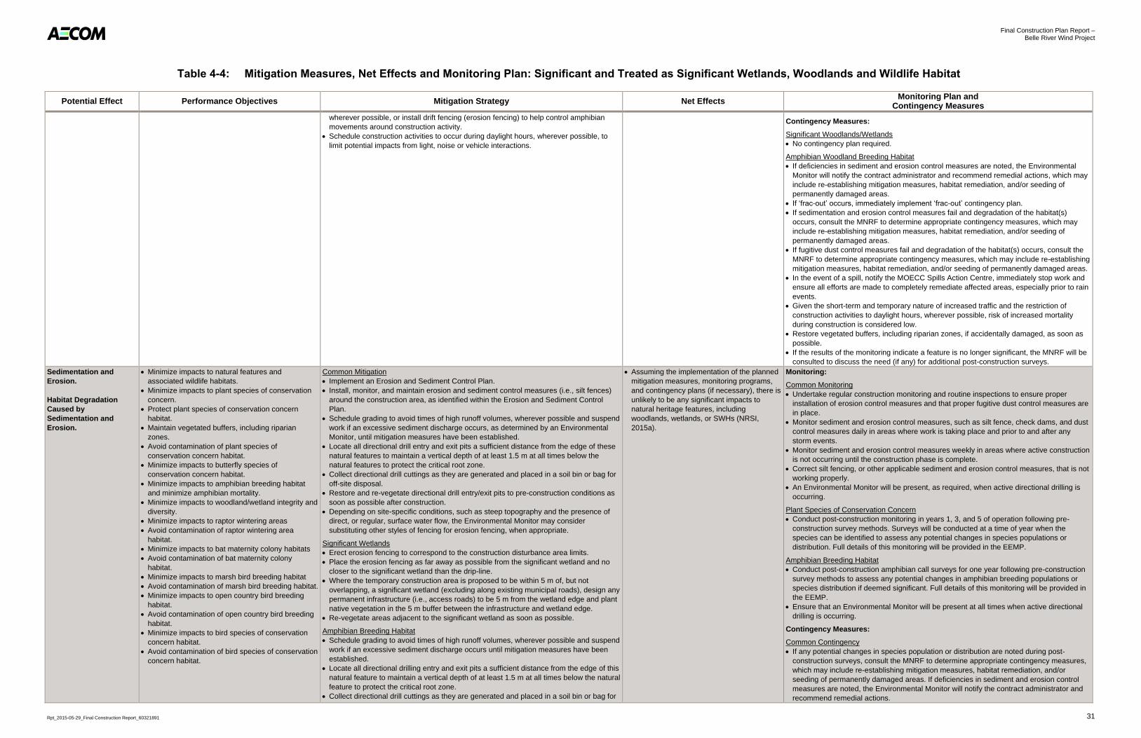
Final Construction Plan Report – Belle River Wind Project
Rpt_2015-05-29_Final Construction Report_60321891 31
Table 4-4: Mitigation Measures, Net Effects and Monitoring Plan: Significant and Treated as Significant Wetlands, Woodlands and Wildlife Habitat
Potential Effect Performance Objectives Mitigation Strategy Net Effects Monitoring Plan and
Contingency Measures
wherever possible, or install drift fencing (erosion fencing) to help control amphibian
movements around construction activity.
Schedule construction activities to occur during daylight hours, wherever possible, to
limit potential impacts from light, noise or vehicle interactions.
Contingency Measures:
Significant Woodlands/Wetlands
No contingency plan required.
Amphibian Woodland Breeding Habitat
If deficiencies in sediment and erosion control measures are noted, the Environmental
Monitor will notify the contract administrator and recommend remedial actions, which may
include re-establishing mitigation measures, habitat remediation, and/or seeding of
permanently damaged areas.
If ‘frac-out’ occurs, immediately implement ‘frac-out’ contingency plan.
If sedimentation and erosion control measures fail and degradation of the habitat(s)
occurs, consult the MNRF to determine appropriate contingency measures, which may
include re-establishing mitigation measures, habitat remediation, and/or seeding of
permanently damaged areas.
If fugitive dust control measures fail and degradation of the habitat(s) occurs, consult the
MNRF to determine appropriate contingency measures, which may include re-establishing
mitigation measures, habitat remediation, and/or seeding of permanently damaged areas.
In the event of a spill, notify the MOECC Spills Action Centre, immediately stop work and
ensure all efforts are made to completely remediate affected areas, especially prior to rain
events.
Given the short-term and temporary nature of increased traffic and the restriction of
construction activities to daylight hours, wherever possible, risk of increased mortality
during construction is considered low.
Restore vegetated buffers, including riparian zones, if accidentally damaged, as soon as
possible.
If the results of the monitoring indicate a feature is no longer significant, the MNRF will be
consulted to discuss the need (if any) for additional post-construction surveys.
Sedimentation and
Erosion.
Habitat Degradation
Caused by
Sedimentation and
Erosion.
Minimize impacts to natural features and
associated wildlife habitats.
Minimize impacts to plant species of conservation
concern.
Protect plant species of conservation concern
habitat.
Maintain vegetated buffers, including riparian
zones.
Avoid contamination of plant species of
conservation concern habitat.
Minimize impacts to butterfly species of
conservation concern habitat.
Minimize impacts to amphibian breeding habitat
and minimize amphibian mortality.
Minimize impacts to woodland/wetland integrity and
diversity.
Minimize impacts to raptor wintering areas
Avoid contamination of raptor wintering area
habitat.
Minimize impacts to bat maternity colony habitats
Avoid contamination of bat maternity colony
habitat.
Minimize impacts to marsh bird breeding habitat
Avoid contamination of marsh bird breeding habitat.
Minimize impacts to open country bird breeding
habitat.
Avoid contamination of open country bird breeding
habitat.
Minimize impacts to bird species of conservation
concern habitat.
Avoid contamination of bird species of conservation
concern habitat.
Common Mitigation
Implement an Erosion and Sediment Control Plan.
Install, monitor, and maintain erosion and sediment control measures (i.e., silt fences)
around the construction area, as identified within the Erosion and Sediment Control
Plan.
Schedule grading to avoid times of high runoff volumes, wherever possible and suspend
work if an excessive sediment discharge occurs, as determined by an Environmental
Monitor, until mitigation measures have been established.
Locate all directional drill entry and exit pits a sufficient distance from the edge of these
natural features to maintain a vertical depth of at least 1.5 m at all times below the
natural features to protect the critical root zone.
Collect directional drill cuttings as they are generated and placed in a soil bin or bag for
off-site disposal.
Restore and re-vegetate directional drill entry/exit pits to pre-construction conditions as
soon as possible after construction.
Depending on site-specific conditions, such as steep topography and the presence of
direct, or regular, surface water flow, the Environmental Monitor may consider
substituting other styles of fencing for erosion fencing, when appropriate.
Significant Wetlands
Erect erosion fencing to correspond to the construction disturbance area limits.
Place the erosion fencing as far away as possible from the significant wetland and no
closer to the significant wetland than the drip-line.
Where the temporary construction area is proposed to be within 5 m of, but not
overlapping, a significant wetland (excluding along existing municipal roads), design any
permanent infrastructure (i.e., access roads) to be 5 m from the wetland edge and plant
native vegetation in the 5 m buffer between the infrastructure and wetland edge.
Re-vegetate areas adjacent to the significant wetland as soon as possible.
Amphibian Breeding Habitat
Schedule grading to avoid times of high runoff volumes, wherever possible and suspend
work if an excessive sediment discharge occurs until mitigation measures have been
established.
Locate all directional drilling entry and exit pits a sufficient distance from the edge of this
natural feature to maintain a vertical depth of at least 1.5 m at all times below the natural
feature to protect the critical root zone.
Collect directional drill cuttings as they are generated and placed in a soil bin or bag for
Assuming the implementation of the planned
mitigation measures, monitoring programs,
and contingency plans (if necessary), there is
unlikely to be any significant impacts to
natural heritage features, including
woodlands, wetlands, or SWHs (NRSI,
2015a).
Monitoring:
Common Monitoring
Undertake regular construction monitoring and routine inspections to ensure proper
installation of erosion control measures and that proper fugitive dust control measures are
in place.
Monitor sediment and erosion control measures, such as silt fence, check dams, and dust
control measures daily in areas where work is taking place and prior to and after any
storm events.
Monitor sediment and erosion control measures weekly in areas where active construction
is not occurring until the construction phase is complete.
Correct silt fencing, or other applicable sediment and erosion control measures, that is not
working properly.
An Environmental Monitor will be present, as required, when active directional drilling is
occurring.
Plant Species of Conservation Concern
Conduct post-construction monitoring in years 1, 3, and 5 of operation following pre-
construction survey methods. Surveys will be conducted at a time of year when the
species can be identified to assess any potential changes in species populations or
distribution. Full details of this monitoring will be provided in the EEMP.
Amphibian Breeding Habitat
Conduct post-construction amphibian call surveys for one year following pre-construction
survey methods to assess any potential changes in amphibian breeding populations or
species distribution if deemed significant. Full details of this monitoring will be provided in
the EEMP.
Ensure that an Environmental Monitor will be present at all times when active directional
drilling is occurring.
Contingency Measures:
Common Contingency
If any potential changes in species population or distribution are noted during post-
construction surveys, consult the MNRF to determine appropriate contingency measures,
which may include re-establishing mitigation measures, habitat remediation, and/or
seeding of permanently damaged areas. If deficiencies in sediment and erosion control
measures are noted, the Environmental Monitor will notify the contract administrator and
recommend remedial actions.

Final Construction Plan Report – Belle River Wind Project
Rpt_2015-05-29_Final Construction Report_60321891 32
Table 4-4: Mitigation Measures, Net Effects and Monitoring Plan: Significant and Treated as Significant Wetlands, Woodlands and Wildlife Habitat
Potential Effect Performance Objectives Mitigation Strategy Net Effects Monitoring Plan and
Contingency Measures
off-site disposal. Restore and re-vegetate directional drill entry/exit pits to pre-
construction conditions as soon as possible after construction.
If ‘frac-out’ occurs, immediately implement ‘frac-out’ contingency plan.
If sedimentation and erosion control measures and degradation of the natural feature
occurs, consult the MNRF to determine appropriate contingency measures, which may
include re-establishing mitigation measures, habitat remediation, and/or seeding of
permanently damaged areas.
In the event of a spill, notify the MOECC Spills Action Centre, immediately stop work, and
ensure all efforts are made to completely remediate affected areas, especially prior to rain
events.
Restore vegetated buffers, including riparian zones, if accidentally damaged, as soon as
possible.
Amphibian Breeding Habitat
If ‘frac-out’ occurs, immediately implement ‘frac-out’ contingency plan.
If sedimentation and erosion control measures fail and degradation of the habitat(s)
occurs, consult the MNRF to determine appropriate contingency measures, which may
include re-establishing mitigation measures, habitat remediation, and/or seeding of
permanently damaged areas.
If fugitive dust control measures fail and degradation of the habitat(s) occurs, consult the
MNRF to determine appropriate contingency measures, which may include re-establishing
mitigation measures, habitat remediation, and/or seeding of permanently damaged areas.
Given the short-term and temporary nature of increased traffic and the restriction of
construction activities to daylight hours, risk of increased mortality during construction is
considered low.
Restore vegetated buffers, including riparian zones, if accidentally damaged, as soon as
possible.
If the results of the monitoring indicate a feature is no longer significant, consult the MNRF
to discuss the need (if any) for additional post-construction surveys.
Fugitive Dust Emission.
Habitat Degradation
Caused by Fugitive Dust
Emission.
Minimize impacts to natural features and
associated wildlife habitats.
Minimize impacts to plant species of conservation
concern.
Protect plant species of conservation concern
habitat.
Maintain vegetated buffers, including riparian
zones.
Avoid contamination of plant species of
conservation concern habitat.
Minimize impacts to amphibian breeding habitat
and minimize amphibian mortality.
Minimize impacts to woodland/wetland integrity and
diversity.
Minimize impacts to raptor wintering areas.
Avoid contamination of raptor wintering area
habitat.
Minimize impacts to bat maternity colony habitats
Avoid contamination of bat maternity colony
habitat.
Minimize impacts to marsh bird breeding habitat.
Avoid contamination of marsh bird breeding habitat.
Minimize impacts to open country bird breeding
habitat.
Avoid contamination of open country bird breeding
habitat.
Minimize impacts to bird species of conservation
concern habitat.
Avoid contamination of bird species of conservation
concern habitat.
Minimize impacts to butterfly species of
conservation concern habitat.
Avoid contamination of butterfly species of
conservation concern habitat.
Common Mitigation
Implement and enforce speed limits for construction equipment and trucks.
Apply dust suppressants to unpaved areas when necessary to suppress dust, as
determined by the Environmental Monitor. Application frequency will vary, but will be
determined by site-specific weather conditions, including recent precipitation,
temperatures, and wind speeds. Input from the construction team may also warrant an
increased frequency of dust suppression.
Re-vegetate cleared areas as soon as reasonably possible.
Significant Wetlands
Install wind fences, where determined to be necessary by the on-site Environmental
Monitor. Installation of these fences will depend on site-specific conditions, including
wind speeds, topography, land cover, and the extent of surrounding natural wind
breaks. Where the temporary construction area is proposed to be within 5 m of, but not
overlapping, a wetland (excluding along existing municipal roads), place any permanent
infrastructure (i.e., access roads) 5 m from the wetland edge and plant native vegetation
in the 5 m buffer between the infrastructure and wetland edge.
Re-vegetate areas adjacent to the wetland as soon as possible.
Assuming the implementation of the planned
mitigation measures, monitoring programs,
and contingency plans (if necessary), there is
unlikely to be any significant impacts to
natural heritage features, including
woodlands, wetlands, or SWHs (NRSI,
2015a).
Monitoring:
Common Monitoring
Undertake regular construction monitoring and routine inspections to ensure proper
installation of erosion control measures and that proper fugitive dust control measures are
in place.
Monitor sediment and erosion control measures, such as silt fences, check dams, and
dust control measures daily in areas where work is taking place and prior to and after any
storm events.
Monitor sediment and erosion control measures twice weekly in areas where active
construction is not occurring until the construction phase is complete.
Correct silt fencing, or other applicable sediment and erosion control measures, that is not
working properly.
Ensure an Environmental Monitor is present at all times when active directional drilling is
occurring.
If fugitive dust control measures fail or negative impacts are observed, consult the MNRF
on the appropriate action(s) to be taken.
Plant Species of Conservation Concern
Conduct post-construction monitoring in years 1, 3, and 5 of operation following pre-
construction survey methods. Surveys will be conducted at a time of year when the
species can be identified to assess any potential changes in species populations or
distribution. Full details of this monitoring will be provided in the EEMP.
Amphibian Breeding Habitat
Conduct post-construction amphibian call surveys for one year following pre-construction
survey methods to assess any potential changes in amphibian breeding populations or
species distribution if deemed significant. Full details of this monitoring will be provided in
the EEMP.
An Environmental Monitor will be present at all times when active directional drilling is
occurring.
Contingency Measures:
Common Contingency Measures
If deficiencies in sediment and erosion control measures are noted, the Environmental
Monitor will notify the contract administrator and recommend remedial actions.
If sedimentation and erosion control measures fail and degradation of the natural feature
occurs, consult the MNRF to determine appropriate contingency measures, which may

Final Construction Plan Report – Belle River Wind Project
Rpt_2015-05-29_Final Construction Report_60321891 33
Table 4-4: Mitigation Measures, Net Effects and Monitoring Plan: Significant and Treated as Significant Wetlands, Woodlands and Wildlife Habitat
Potential Effect Performance Objectives Mitigation Strategy Net Effects Monitoring Plan and
Contingency Measures
include re-establishing mitigation measures, habitat remediation, and/or seeding of
permanently damaged areas.
If ‘frac-out’ occurs, immediately implement ‘frac-out’ contingency plan.
If fugitive dust control measures fail and degradation of the natural feature occurs, consult
the MNRF to determine appropriate contingency measures, which may include re-
establishing mitigation measures, habitat remediation, and/or seeding of permanently
damaged areas.
In the event of a spill, notify the MOECC Spills Action Centre, immediately stop work, and
ensure all efforts are made to completely remediate affected areas, especially prior to rain
events.
Restore vegetated buffers, including riparian zones, if accidentally damaged, as soon as
possible.
Plant Species of Conservation Concern
Restore vegetated buffers, including riparian zones, if accidentally damaged, as soon as
possible.
Amphibian Breeding Habitat
If ‘frac-out’ occurs, immediately implement ‘frac-out’ contingency plan.
If sedimentation and erosion control measures fail and degradation of the habitat(s)
occurs, consult the MNRF to determine appropriate contingency measures, which may
include re-establishing mitigation measures, habitat remediation, and/or seeding of
permanently damaged areas.
If fugitive dust control measures fail and degradation of the habitat(s) occurs, consult the
MNRF to determine appropriate contingency measures, which may include re-establishing
mitigation measures, habitat remediation, and/or seeding of permanently damaged areas.
Given the short-term and temporary nature of increased traffic and the restriction of
construction activities to daylight hours, risk of increased mortality during construction is
considered low.
Restore vegetated buffers, including riparian zones, if accidentally damaged, as soon as
possible.
If the results of the monitoring indicate a feature is no longer significant, the MNRF will be
consulted to discuss the need (if any) for additional post-construction surveys.
Spills
(i.e., oil, gasoline,
grease, etc.).
Habitat Degradation
Caused by Spills
(i.e., oil, gasoline,
grease, etc.).
Minimize impacts to natural features and
associated wildlife habitats.
Maintain vegetated buffers, including riparian
zones.
Minimize impacts to plant species of conservation
concern.
Protect plant species of conservation concern
habitat.
Maintain vegetated buffers, including riparian zones.
Avoid contamination of plant species of
conservation concern habitat.
Minimize impacts to raptor wintering areas.
Avoid contamination of raptor wintering area
habitat.
Minimize impacts to bat maternity colony habitats
Avoid contamination of bat maternity colony
habitat.
Minimize impacts to amphibian breeding habitat
and minimize amphibian mortality.
Minimize impacts to woodland/wetland integrity and
diversity.
Minimize impacts to marsh bird breeding habitat.
Avoid contamination of marsh bird breeding habitat.
Minimize impacts to open country bird breeding
habitat.
Avoid contamination of open country bird breeding
habitat.
Minimize impacts to bird species of conservation
concern habitat.
Avoid contamination of bird species of conservation
concern habitat.
Common Mitigation
Develop a SRP and train staff on appropriate procedures.
Develop a ‘frac-out’ contingency plan and train staff on appropriate procedures.
Keep emergency spill kits on site.
Keep contact information for the MOECC Spills Action Centre in all vehicles as well as
posted in a designated area on the construction site.
Dispose of waste material by authorized and approved off-site vendors.
Store hazardous materials in designated areas.
Locate all maintenance activities, vehicle refueling or washing, as well as the storage of
chemical and construction equipment more than 30 m from significant features.
Amphibian Breeding Habitat
Develop a ‘frac-out’ contingency plan and train staff on appropriate procedures.
Assuming the implementation of the planned
mitigation measures, monitoring programs,
and contingency plans (if necessary), there is
unlikely to be any significant impacts to
natural heritage features, including
woodlands, wetlands, or SWHs (NRSI,
2015a).
Monitoring:
Common Monitoring
Undertake regular construction monitoring and routine inspections to ensure proper
installation of erosion control measures and that proper fugitive dust control measures are
in place.
Monitor sediment and erosion control measures, such as silt fence, check dams, and dust
control measures daily in areas where work is taking place and prior to and after any
storm events.
Monitor sediment and erosion control measures weekly in areas where active construction
is not occurring until the construction phase is complete.
Correct silt fencing, or other applicable sediment and erosion control measures, that is not
working properly.
Conduct post-construction behaviour surveys of the habitat for three years following pre-
construction survey methods to assess the potential project disturbance on all habitats
deemed significant. Full details of this monitoring will be provided in the EEMP.
An Environmental Monitor will be present at all times when active directional drilling is
occurring.
Butterfly Species of Conservation Concern
Conduct one year of post-construction surveys of the habitat to assess the potential
project disturbance on this habitat. Full details of this monitoring will be provided in the
EEMP.
Plant Species of Conservation Concern
Conduct post-construction monitoring in years 1, 3, and 5 of operation following pre-
construction survey methods. Surveys will be conducted at a time of year when the
species can be identified to assess any potential changes in species populations or
distribution. Full details of this monitoring will be provided in the EEMP.
Amphibian Breeding Habitat
Conduct post-construction amphibian call surveys for one year following pre-construction
survey methods to assess any potential changes in amphibian breeding populations or

Final Construction Plan Report – Belle River Wind Project
Rpt_2015-05-29_Final Construction Report_60321891 34
Table 4-4: Mitigation Measures, Net Effects and Monitoring Plan: Significant and Treated as Significant Wetlands, Woodlands and Wildlife Habitat
Potential Effect Performance Objectives Mitigation Strategy Net Effects Monitoring Plan and
Contingency Measures
Minimize impacts to woodland/wetland integrity and
diversity.
Minimize impacts to butterfly species of
conservation concern habitat.
Avoid contamination of butterfly species of
conservation concern habitat.
species distribution if deemed significant. Full details of this monitoring will be provided in
the EEMP.
An Environmental Monitor will be present at all times when active directional drilling is
occurring.
Contingency Measures:
Common Contingency
If deficiencies in sediment and erosion control measures are noted, the Environmental
Monitor will notify the contract administrator and recommend remedial actions.
If sedimentation and erosion control measures fail and degradation of the natural feature
occurs, consult the MNRF to determine appropriate contingency measures, which may
include re-establishing mitigation measures, habitat remediation, and/or seeding of
permanently damaged areas.
If fugitive dust control measures fail or and degradation of the natural feature occurs,
consult the MNRF to determine appropriate contingency measures, which may include re-
establishing mitigation measures, habitat remediation, and/or seeding of permanently
damaged areas
In the event of a spill, notify the MOECC Spills Action Centre, immediately stop work, and
ensure all efforts are made to completely remediate affected areas, especially prior to rain
events.
Restore vegetated buffers, including riparian zones, if accidentally damaged, as soon as
possible.
If any potential changes in species population or distribution are noted during post-
construction surveys, consult the MNRF to determine appropriate contingency measures,
which may include re-establishing mitigation measures, habitat remediation, and/or
seeding of permanently damaged areas.
If ‘frac-out’ occurs, immediately implement ‘frac-out’ contingency plan.
Amphibian Breeding Habitat
If ‘frac-out’ occurs, immediately implement ‘frac-out’ contingency plan.
If sedimentation and erosion control measures fail and degradation of the habitat(s)
occurs, consult the MNRF to determine appropriate contingency measures, which may
include re-establishing mitigation measures, habitat remediation, and/or seeding of
permanently damaged areas.
If fugitive dust control measures fail and degradation of the habitat(s) occurs, consult the
MNRF to determine appropriate contingency measures, which may include re-establishing
mitigation measures, habitat remediation, and/or seeding of permanently damaged areas.
Given the short-term and temporary nature of increased traffic and the restriction of
construction activities to daylight hours, risk of increased mortality during construction is
considered low.
Restore vegetated buffers, including riparian zones, if accidentally damaged, as soon as
possible.
If the results of the monitoring indicate a feature is no longer significant, the MNRF will be
consulted to discuss the need (if any) for additional post-construction surveys.
Changes in Soil Moisture
and Compaction.
Minimize impact to soil moisture regime and
vegetation species composition.
Common Mitigation
Minimize the use of impervious surfaces where possible, such as utilizing and
contouring permeable surface material (i.e., gravel) to increase infiltration, and reduce
surface water runoff.
Minimize paved surfaces and design roads to promote infiltration.
Significant Woodlands
Clearly delineate the drip-line and root zone of all trees within 10 m of construction
activities with erosion fencing or similar barrier.
Assuming the implementation of the planned
mitigation measures, monitoring programs,
and contingency plans (if necessary), there is
unlikely to be any significant impacts to
natural heritage features, including
woodlands, wetlands, or SWH (NRSI,
2015a).
Monitoring and Contingency Measures:
No monitoring or contingency plan required.

Final Construction Plan Report – Belle River Wind Project
Rpt_2015-05-29_Final Construction Report_60321891 35
Table 4-4: Mitigation Measures, Net Effects and Monitoring Plan: Significant and Treated as Significant Wetlands, Woodlands and Wildlife Habitat
Potential Effect Performance Objectives Mitigation Strategy Net Effects Monitoring Plan and
Contingency Measures
Accidental Vegetation
Removal from Significant
Woodlands
(Project Location is sited
outside of Significant
Woodlands – impact to
vegetation is not
anticipated).
Minimize direct impacts on vegetation communities
and protect rare / sensitive habitats.
Clearly delineate work area using erosion fencing, or other barriers, to avoid accidental
damage to retained species.
Where construction is within 10 m of a significant woodland, erect erosion fencing to
correspond to the disturbance area limits.
Place the erosion fencing as far away as possible from the significant woodland and no
closer to the significant woodland than the drip-line.
Depending on site-specific conditions, such as steep topography and the presence of
direct, or regular, surface water flow, the Environmental Monitor may consider
substituting other styles of fencing for erosion fencing, when appropriate. The
Environmental Monitor may also consider substituting other demarcating types for
fencing, such as staking and flagging, where it is determined that there is no apparent
risk to nearby natural features. This could include situations where the natural feature is
at higher elevation than construction activity.
No use of herbicides (project related activities only) within significant features or wildlife
habitats.
Assuming the implementation of the planned
mitigation measures, monitoring programs,
and contingency plans (if necessary), there is
unlikely to be any significant impacts to
natural heritage features, including
woodlands, wetlands, or SWHs (NRSI,
2015a).
Monitoring:
Undertake regular monitoring of the drip-line to ensure the work area is clearly delineated
within 10 m of construction activities for the duration of the construction and
decommissioning phases of this project. This monitoring will be conducted at a minimum
frequency of once per week when construction is anticipated within 10 m of a significant
woodland.
Undertake regular monitoring of the drip-line to ensure the work area is clearly delineated
and drip-line boundaries are respected when construction is anticipated to occur within 10
to 30 m of significant woodlands, at a minimum frequency of once per month.
Contingency Measures:
Prune any tree limbs or roots that are accidentally damaged by construction activities
using proper arboricultural techniques.
Accidental damage to trees, or unexpected vegetation removal, may require re-planting of
similar, native species. If re-planting is required , a re-planting strategy will be provided to
the MNRF.
Reduced Flood
Attenuation in
Significant Wetlands.
Minimize direct impacts on vegetation communities
and protect rare/sensitive habitats.
Minimize impacts to hydrological connectivity.
Minimize impacts to water quality.
Clearly delineate work area using erosion fencing, or other barrier, to avoid accidental
damage to retained wetland vegetation and to avoid impacting hydrological connectivity.
Depending on site-specific conditions, such as steep topography and the presence of
direct, or regular, surface water flow patterns, the Environmental Monitor may consider
substituting other styles of fencing for erosion fencing, when appropriate.
Re-vegetate cleared areas as soon as reasonably possible.
Where the temporary construction area is proposed to be within 5 m of, but not
overlapping, a Significant Wetland (excluding along existing municipal roads), design
any permanent infrastructure (i.e., access roads) to be 5 m from the wetland edge and
plant native vegetation in the 5 m buffer between the infrastructure and wetland edge.
Assuming the implementation of the planned
mitigation measures, monitoring programs,
and contingency plans (if necessary), there is
unlikely to be any significant impacts to
natural heritage features, including
woodlands, wetlands, or SWHs (NRSI,
2015a).
Monitoring:
Undertake regular monitoring of the Significant Wetland to ensure proper erosion and
sediment control measures, including fencing, are in place within 10 m of construction
activities for the duration of the construction and decommissioning phases of the project.
This monitoring will be conducted at a minimum frequency of once per week when
construction is anticipated within 10 m of a significant wetland.
Undertake regular monitoring of the wetland to ensure proper erosion and sediment
control measures, including fencing, are in place when construction is anticipated to occur
within 10 to 30 m of significant wetlands, at a minimum frequency of once per month.
Depending on the season and site-specific conditions, such as topography, surface water
flow patterns, and the presence or absence of vegetative buffers, monitoring frequency
will be increased at the discretion of the Environmental Monitor.
Contingency Measures:
If sedimentation and erosion or fugitive dust control measures fail and degradation of the
natural feature occurs, consult the MNRF to determine appropriate contingency
measures, which may include re-establishing mitigation measures, habitat remediation,
and/or seeding of permanently damaged areas.
If negative impacts such as reduced water quality, infiltration and/or groundwater
discharge are observed, consult the MNRF to determine appropriate contingency
measures.
Reduced Water Quality
in Significant Wetlands.
Minimize direct impacts on vegetation communities
and protect rare/sensitive habitats.
Minimize impacts to hydrological connectivity.
Minimize impacts to water quality.
Clearly delineate work area using erosion fencing, or other barrier, to avoid accidental
damage to retained wetland vegetation and to avoid impacting water quality.
Depending on site-specific conditions, such as steep topography and the presence of
direct, or regular, surface water flow, the Environmental Monitor may consider
substituting other styles of fencing for erosion fencing, when appropriate.
Implement and enforce speed limits for construction equipment and trucks.
Apply dust suppressants to unpaved areas when necessary to suppress dust, as
determined by the Environmental Monitor. Application frequency will vary, but will be
determined by site-specific weather conditions, including recent precipitation,
temperatures, and wind speeds. Input from the construction team may also warrant an
increased frequency of dust suppression. Re-vegetate areas adjacent to the wetland as
soon as possible.
Install wind fences, where determined to be necessary by the on-site Environmental
Monitor. Installation of these fences will depend on site-specific conditions, including
wind speeds, topography, land cover, and the extent of surrounding natural wind
breaks. Where the temporary construction area is proposed to be within 5 m of, but not
overlapping, a wetland (excluding along existing municipal roads), design any
permanent infrastructure (i.e., access roads) to be 5 m from the wetland edge and plant
native vegetation in the 5 m buffer between the infrastructure and wetland edge.
Assuming the implementation of the planned
mitigation measures, monitoring programs,
and contingency plans (if necessary), there is
unlikely to be any significant impacts to
natural heritage features, including
woodlands, wetlands, or SWHs (NRSI,
2015a).
Monitoring:
Undertake regular monitoring of the Significant Wetland to ensure proper erosion and
sediment control measures, including fencing, are in place within 10 m of construction
activities for the duration of the construction and decommissioning phases of the project.
This monitoring will be conducted at a minimum frequency of once per week when
construction is anticipated within 10 m of a significant wetland.
Undertake regular monitoring of the wetland to ensure proper erosion and sediment
control measures, including fencing, are in place when construction is anticipated to occur
within 10 to 30 m of a Significant Wetland, at a minimum frequency of once per month.
Depending on the season and site-specific conditions, such as topography, surface water
flow patterns, and the presence or absence of vegetative buffers, monitoring frequency
will be increased at the discretion of the Environmental Monitor.
Contingency Measures:
If sedimentation and erosion or fugitive dust control measures fail and degradation of the
natural feature occurs, consult the MNRF to determine appropriate contingency
measures, which may include re-establishing mitigation measures, habitat remediation,
and/or seeding of permanently damaged areas.
If negative impacts such as reduced water quality, infiltration and/or groundwater
discharge are observed, consult the MNRF to determine appropriate contingency
measures.

Final Construction Plan Report – Belle River Wind Project
Rpt_2015-05-29_Final Construction Report_60321891 36
Table 4-4: Mitigation Measures, Net Effects and Monitoring Plan: Significant and Treated as Significant Wetlands, Woodlands and Wildlife Habitat
Potential Effect Performance Objectives Mitigation Strategy Net Effects Monitoring Plan and
Contingency Measures
Reduced Infiltration and
Groundwater Discharge
in Significant Wetlands.
Minimize direct impacts on vegetation communities
and protect rare / sensitive habitats.
Minimize impacts to hydrological connectivity.
Minimize impacts to water quality.
Minimize the use of impervious surfaces where possible, such as utilizing and
contouring permeable surface material (i.e., gravel) to increase infiltration and reduce
surface water runoff.
For groundwater taking (if necessary):
Control rate and timing of water pumping.
Restrict taking of groundwater and surface water during extreme low flow time periods.
Control quantity and quality of stormwater discharge using BMPs, and avoid direct
discharge into wetlands or watercourses.
Assuming the implementation of the planned
mitigation measures, monitoring programs,
and contingency plans (if necessary), there is
unlikely to be any significant impacts to
natural heritage features, including
woodlands, wetlands, or SWH (NRSI,
2015a).
Monitoring:
Undertake regular monitoring of the Significant Wetland to ensure proper erosion and
sediment control measures, including fencing, are in place within 10 m of construction
activities for the duration of the construction and decommissioning phases of the project.
This monitoring will be conducted at a minimum frequency of once per week when
construction is anticipated within 10 m of a Significant Wetland.
Undertake regular monitoring of the Significant Wetland to ensure proper erosion and
sediment control measures, including fencing, are in place when construction is anticipated
to occur within 10 to 30 m of a Significant Wetland, at a minimum frequency of once per
month. Depending on the season and site-specific conditions, such as topography, surface
water flow patterns, and the presence or absence of vegetative buffers, monitoring frequency
will be increased at the discretion of the Environmental Monitor.
Contingency Measures:
If sedimentation and erosion or fugitive dust control measures fail and degradation of the
natural feature occurs, consult the MNRF to determine appropriate contingency
measures, which may include re-establishing mitigation measures, habitat remediation,
and/or seeding of permanently damaged areas.
If negative impacts such as reduced water quality, infiltration and/or groundwater
discharge are observed, consult the MNRF to determine appropriate contingency
measures.
Noise Disturbance /
Avoidance Behaviour.
Minimize disturbance / avoidance behavior of
butterfly species of conservation concern.
Protect bat maternity colony habitat.
Minimize impacts to marsh bird breeding habitat
and minimize marsh bird mortality.
Minimize impacts to wetland integrity and diversity.
Protect open country bird breeding habitat.
Minimize noise disturbance/avoidance behavior of
bird species of conservation concern.
Bat Maternity Colony
Impacts are expected to be minimal, and temporary, in nature, and no specific mitigation
measures have been determined necessary.
Schedule construction and regular (non-critical) maintenance activities to occur outside
of the critical roosting period (June), unless specifically required in accordance with
manufacturer specifications.
Marsh Bird Breeding habitat
Schedule construction and regular (non-critical) maintenance activities to occur outside
of the peak marsh bird breeding season (April – June), wherever possible.
If construction must occur during this peak breeding season, have a biologist present to
confirm birds will not be affected by construction activities.
Open Country Breeding Bird Habitat
Clearly delineate work area using erosion fencing, or other barrier, to avoid accidental
damage to breeding habitat.
Depending on site-specific conditions, such as steep topography and the presence of
direct, or regular, surface water flow, the Environmental Monitor may consider
substituting other styles of fencing for erosion fencing, when appropriate.
Restore temporary construction areas, including crane paths and turbine pads, to pre-
construction conditions as soon as possible.
Schedule construction activities to occur outside of the peak breeding bird season (May
1st – July 31
st), wherever possible.
If construction must occur during the breeding bird period (May 1st – July 31
st), have a
biologist present to confirm no nests will be affected by construction.
Bird Species of Conservation Concern
Schedule construction and regular (non-critical) maintenance activities located within 30
m of significant bird species of conservation concern habitat to occur outside of the peak
breeding bird season (May 1st
– July 31st), whenever possible.
If construction and maintenance must occur during the breeding bird period (May 1st –
July 31st), have a biologist present to confirm birds will not be affected by construction or
maintenance activities.
Butterfly Species of Conservation Concern
Schedule construction and regular (non-critical) maintenance activities located within 30
m of significant butterfly species of conservation concern habitat to occur outside of the
flight period for when this species is likely to be encountered (late June to early August),
whenever possible.
If construction and maintenance must occur during the peak flight period, have a
biologist present to confirm that this species will not be affected by construction or
maintenance activities.
Assuming the implementation of the planned
mitigation measures, monitoring programs,
and contingency plans (if necessary), there is
unlikely to be any significant impacts to
natural heritage features, including
woodlands, wetlands, or SWHs (NRSI,
2015a).
Monitoring:
Marsh Bird Breeding habitat/Open Country Breeding Bird Habitat/Bird Species of
Conservation Concern
Conduct post-construction behaviour surveys of the habitat for three years following pre-
construction survey methods to assess the potential project disturbance on all habitats
deemed significant. Full details of this monitoring will be provided in the EEMP.
Bat Maternity Colony
Conduct post-construction monitoring of this feature for three years after construction,
following pre-construction methods, for all features deemed significant. Full details of this
monitoring will be provided in the EEMP.
Conduct post-construction mortality monitoring at this facility for at least three years
following MNRF guidelines (MNRF, 2011b). The turbine closest to this habitat (T19) will be
included with the subsample of turbines monitored during post-construction mortality
monitoring, if this habitat is confirmed to be significant. Full details of this monitoring will
be provided within the EEMP.
Butterfly Species of Conservation Concern
Conduct one year of post-construction surveys of the habitat to assess the potential
project disturbance on this habitat. Full details of this monitoring will be provided in the
EEMP.
Contingency Measures:
Bat Maternity Colony
If a permanent disturbance has been noted within this wildlife habitat, the MNRF will be
contacted to determine whether additional mitigation measures will be needed.
If high bat mortality is observed at T19, discuss appropriate mitigation measures with the
MNRF.
Marsh Bird Breeding habitat/ Open Country Breeding Bird Habitat
If a permanent disturbance has been noted within this wildlife habitat, consult the MNRF
to determine whether additional mitigation measures will be needed.
Bird Species of Conservation Concern
If considerable, and consistent, disturbance impacts are noted, discuss appropriate
mitigation measures directly with the MNRF.
Butterfly Species of Conservation Concern
If the results of the monitoring indicate a feature is no longer significant, consult the MNRF
to discuss the need (if any) for additional post-construction surveys.

Final Construction Plan Report – Belle River Wind Project
Rpt_2015-05-29_Final Construction Report_60321891 37
Table 4-4: Mitigation Measures, Net Effects and Monitoring Plan: Significant and Treated as Significant Wetlands, Woodlands and Wildlife Habitat
Potential Effect Performance Objectives Mitigation Strategy Net Effects Monitoring Plan and
Contingency Measures
Accidental Loss
of Habitat
(damage to vegetation,
including root zones).
Minimize impacts to amphibian breeding habitat
and minimize amphibian mortality.
Minimize impacts to woodland / wetland integrity
and diversity.
Minimize impacts to bird species of conservation
concern habitat.
Minimize direct impacts to butterfly species of
conservation concern habitat.
Minimize impacts to marsh bird breeding habitat
and minimize marsh bird mortality.
Minimize impacts to wetland integrity and diversity.
Protection of open country bird breeding habitat.
Common Mitigation
Clearly delineate work area using erosion fencing, or other barrier, to avoid accidental
vegetation damage within amphibian breeding habitat.
Depending on site-specific conditions, such as topography and surface water flow
patterns, the Environmental Monitor may consider substituting other styles of fencing for
erosion fencing, when appropriate.
No use of herbicides (project related activities only) within significant features or wildlife
habitats.
Directional drilling entry and exit pits will be located at a sufficient distance from the
edge of the natural feature to maintain a vertical depth of at least 1.5 m at all times
below the natural feature to protect the critical root zone.
Directional drilling will be a minimum of 1.5 m below the surface of this habitat.
Amphibian Woodland Breeding
Avoid direct impacts to specific breeding habitat (i.e., vernal pools or other aquatic
habitat), or to the immediately surrounding woodland habitat.
Bird Species of Conservation Concern
Restore temporary construction areas to pre-construction conditions as soon as
possible.
Butterfly Species of Conservation Concern
Clearly delineate work area using erosion fencing, or other barrier, to avoid accidental
damage to butterfly species of conservation concern habitat.
Restore temporary construction areas to pre-construction conditions as soon as
possible.
Assuming the implementation of the planned
mitigation measures, monitoring programs,
and contingency plans (if necessary), there is
unlikely to be any significant impacts to
natural heritage features, including
woodlands, wetlands, or SWHs (NRSI,
2015a).
Given the short-term and temporary nature of
increased traffic and the restriction of
construction activities to daylight hours, risk
of increased mortality during construction is
considered low.
Monitoring:
Amphibian Woodland Breeding
Conduct post-construction amphibian call surveys for one year following pre-construction
survey methods to assess any potential changes in amphibian breeding populations or species
distribution if deemed significant. Full details of this monitoring will be provided in the EEMP.
Undertake regular construction monitoring and routine inspections to ensure proper installation
of erosion control measures and that proper fugitive dust control measures are in place.
Monitor sediment and erosion control measures, such as silt fence, check dams, and dust
control measures daily in areas where work is taking place and prior to and after any
storm events.
Monitor sediment and erosion control measures weekly in areas where active construction
is not occurring until the construction phase is complete.
Correct silt fencing, or other applicable sediment and erosion control measures, that is not
working properly.
An Environmental Monitor will be present, as required, when active directional drilling is
occurring.
Bird Species of Conservation Concern
Conduct post-construction behaviour surveys of this habitat for three years following pre-
construction survey methods to assess the potential project disturbance on this habitat.
Full details of this monitoring will be provided within the EEMP.
Butterfly Species of Conservation Concern
Conduct one year of post-construction surveys of the habitat to assess the potential project
disturbance on this habitat. Full details of this monitoring will be provided in the EEMP.
Marsh Bird Breeding Habitat/Open Country Breeding Birds
Conduct post-construction monitoring of this feature for three years after construction,
following pre-construction methods, for all features deemed significant. Full details of this
monitoring will be provided within the EEMP.
Contingency Measures:
Amphibian Woodland Breeding
If deficiencies in sediment and erosion control measures are noted, the Environmental
Monitor will notify the contract administrator and recommend remedial actions, which may
include re-establishing mitigation measures, habitat remediation, and/or seeding of
permanently damaged areas.
If ‘frac-out’ occurs, immediately implement ‘frac-out’ contingency plan.
If sedimentation and erosion control measures fail and degradation of the habitat(s)
occurs, consult the MNRF to determine appropriate contingency measures, which may
include re-establishing mitigation measures, habitat remediation, and/or seeding of
permanently damaged areas.
If fugitive dust control measures fail and degradation of the habitat(s) occurs, consult the
MNRF to determine appropriate contingency measures, which may include re-establishing
mitigation measures, habitat remediation, and/or seeding of permanently damaged areas.
In the event of a spill, notify the MOECC Spills Action Centre, immediately stop work and
ensure all efforts are made to completely remediate affected areas, especially prior to rain
events.
Given the short-term and temporary nature of increased traffic and the restriction of
construction activities to daylight hours, wherever possible, risk of increased mortality
during construction is considered low.
Restore vegetated buffers, including riparian zones, if accidentally damaged, as soon as
possible.
If the results of the monitoring indicate a feature is no longer significant, the MNRF will be
consulted to discuss the need (if any) for additional post-construction surveys.
Bird Species of Conservation Concern
Maintain bird species of conservation concern habitat quality and quantity within the
project area, using baseline conditions as a minimum standard.
Butterfly Species of Conservation Concern
Maintain butterfly species of conservation concern habitat within the project area in
consultation with the MNFR, which may include restoring habitats with suitable host plants
for butterfly species of conservation concern.
Marsh Bird Breeding Habitat/Open Country Breeding Birds
If a permanent disturbance has been noted within this wildlife habitat, consult the MNRF
to determine whether additional mitigation measures will be needed.

Final Construction Plan Report – Belle River Wind Project
Rpt_2015-05-29_Final Construction Report_60321891 38
Table 4-4: Mitigation Measures, Net Effects and Monitoring Plan: Significant and Treated as Significant Wetlands, Woodlands and Wildlife Habitat
Potential Effect Performance Objectives Mitigation Strategy Net Effects Monitoring Plan and
Contingency Measures
Increased Species
Competition to Plant
Species of Conservation
Concern through
Introduction of Invasive
Species.
Minimize impacts to plant species of conservation
concern.
Protect plant species of conservation concern
habitat.
Maintain vegetated buffers, including riparian
zones.
Avoid contamination of plant species of
conservation concern habitat.
Clearly delineate work area using erosion fencing, or other barrier, to minimize seed
transfer into suitable habitat.
Depending on site-specific conditions, such as steep topography and presence of direct,
or regular, surface water flow, the Environmental Monitor may consider substituting
other styles of fencing for erosion fencing, when appropriate.
Regularly clean vehicles and equipment.
Vehicle use will occur primarily on access roads and in agricultural habitats, where
invasive and non-native vegetation species are less likely to be concentrated.
Assuming the implementation of the planned
mitigation measures, monitoring programs,
and contingency plans (if necessary), there is
unlikely to be any significant impacts to
natural heritage features, including
woodlands, wetlands, or SWHs (NRSI,
2015a).
Monitoring:
Conduct post-construction monitoring in years 1, 3, and 5 of operation following pre-
construction survey methods. Surveys will be conducted at a time of year when the
species can be identified to assess any potential changes in species populations or
distribution. Full details of this monitoring will be provided in the EEMP.
Undertake regular construction monitoring and routine inspections to ensure proper
installation of erosion control measures and that proper fugitive dust control measures are
in place.
Monitor sediment and erosion control measures, such as silt fence, check dams, and dust
control measures daily in areas where work is taking place and prior to and after any
storm events.
Monitor sediment and erosion control measures weekly in areas where active construction
is not occurring until the construction phase is complete.
Correct silt fencing, or other applicable sediment and erosion control measures, that is not
working properly.
An Environmental Monitor will be present at all times when active directional drilling is
occurring.
Contingency Measures:
If any potential changes in species population or distribution are noted during post-
construction surveys, consult the MNRF to determine appropriate contingency measures,
which may include re-establishing mitigation measures, habitat remediation, and/or
seeding of permanently damaged areas.
Restore vegetated buffers, including riparian zones, if accidentally damaged, as soon as
possible.
If deficiencies in sediment and erosion control measures are noted, the Environmental
Monitor will notify the contract administrator and recommend remedial actions, which may
include re-establishing mitigation measures, habitat remediation, and/or seeding of
permanently damaged areas.
If ‘frac-out’ occurs, immediately implement ‘frac-out’ contingency plan.
If sedimentation and erosion control measures fail and degradation of the habitat(s)
occurs, consult the MNRF to determine appropriate contingency measures, which may
include re-establishing mitigation measures, habitat remediation, and/or seeding of
permanently damaged areas.
If fugitive dust control measures fail and degradation of the habitat(s) occurs, consult the
MNRF to determine appropriate contingency measures, which may include re-establishing
mitigation measures, habitat remediation, and/or seeding of permanently damaged areas.
In the event of a spill, notify the MOECC Spills Action Centre, immediately stop work and
ensure all efforts are made to completely remediate affected areas, especially prior to rain
events.
Accidental Damage to
Raptor Wintering Area
Habitat, Including Tree
Limbs.
Protect raptor wintering area habitat.
Limit disturbance to raptors overwintering within the
project area.
Clearly delineate work area using erosion fencing, or other barrier, to avoid accidental
vegetation damage within significant raptor wintering areas.
No use of herbicides (project related activities only) within significant features or wildlife
habitats.
Assuming the implementation of the planned
mitigation measures, monitoring programs,
and contingency plans (if necessary), there is
unlikely to be any significant impacts to
natural heritage features, including
woodlands, wetlands, or SWHs (NRSI,
2015a).
Monitoring:
Conduct post-construction surveys of this wildlife habitat for one year after construction,
following pre-construction methods if the habitats are deemed significant. Full details of
this monitoring will be provided in the EEMP.
If surveys indicate that there is an avoidance effect, consult with MNRF to determine the
need for an additional two years of post-construction monitoring following pre-construction
methods.
Contingency Measures:
Consult MNRF to determine contingency measures.
Accidental Damage
to Bat Maternity
Colony Habitat,
Including Tree Limbs
(Project locations are sited
outside of habitats –
vegetation removal is not
anticipated).
Protection of bat maternity colony habitat.
Clearly delineate work area using erosion fencing, or other barrier, to avoid accidental
damage to potentially significant bat roosting trees.
Depending on site-specific conditions, such as topography and surface water flow
patterns, the Environmental Monitor may consider substituting other styles of fencing for
erosion fencing, when appropriate.
No use of herbicides (project related activities only) within significant features or wildlife
habitats.
Assuming the implementation of the planned
mitigation measures, monitoring programs,
and contingency plans (if necessary), there is
unlikely to be any significant impacts to
natural heritage features, including
woodlands, wetlands, or SWHs (NRSI,
2015a).
Monitoring:
Conduct post-construction monitoring of this feature for three years after construction,
following pre-construction methods, for all features deemed significant. Full details of this
monitoring will be provided in the EEMP.
Conduct post-construction mortality monitoring at this facility for at least three years
following MNRF guidelines (MNRF, 2011b). The turbine closest to this habitat (T19) will be
included with the subsample of turbines monitored during post-construction mortality
monitoring, if this habitat is confirmed to be significant. Full details of this monitoring will
be provided within the EEMP.
Contingency Measures:
If a permanent disturbance has been noted within this wildlife habitat, contact the MNRF
to determine whether additional mitigation measures will be needed.
If high bat mortality is observed at T19, discuss appropriate mitigation measures with the
MNRF.

Final Construction Plan Report – Belle River Wind Project
Rpt_2015-05-29_Final Construction Report_60321891 39
Table 4-4: Mitigation Measures, Net Effects and Monitoring Plan: Significant and Treated as Significant Wetlands, Woodlands and Wildlife Habitat
Potential Effect Performance Objectives Mitigation Strategy Net Effects Monitoring Plan and
Contingency Measures
Accidental Damage to
Plant Species of
Conservation Concern.
Minimize direct impacts to plant species of
conservation concern.
Protect plant species of conservation concern
habitat.
Minimize impacts on current species composition.
Reduce the potential spread of non-native or
invasive species.
Clearly delineate work area using erosion fencing, or similar barrier, to avoid accidental
damage to species to be retained and habitat.
Depending on site-specific conditions, such as steep topography and the presence of
direct, or regular, surface water flow, the Environmental Monitor may consider
substituting other styles of fencing for erosion fencing, when appropriate.
Directional drilling entry and exit pits will be located a sufficient distance from the edge
of the natural feature to maintain a vertical depth of at least 1.5 m at all times below the
natural feature to protect the critical root zone.
Directional drilling will be a minimum of 1.5 m below the surface of this habitat.
No use of herbicides (project related activities only) within significant features or wildlife
habitats.
Re-vegetate cleared areas as soon as reasonably possible.
Assuming the implementation of the planned
mitigation measures, monitoring programs,
and contingency plans (if necessary), there is
unlikely to be any significant impacts to
natural heritage features, including
woodlands, wetlands, or SWHs (NRSI,
2015a).
Monitoring:
Conduct post-construction monitoring in years 1, 3, and 5 of operation following pre-
construction survey methods. Surveys will be conducted at a time of year when the
species can be identified to assess any potential changes in species populations or
distribution. Full details of this monitoring will be provided within the EEMP.
Contingency Measures:
Replace any plant species of conservation concern which are damaged or destroyed at a
1:1 ratio with plantings in the habitat. The success of any planted specimens will be
monitored for two years after planting.
If any potential changes in species populations or distribution are noted during post-
construction surveys, consult the MNRF to determine appropriate contingency measures,
which may include re-establishing mitigation measures, habitat remediation, and/or
seeding of permanently damaged areas.

Final Construction Plan Report – Belle River Wind Project
Rpt_2015-05-29_Final Construction Report_60321891 40
4.3 Impacts to Water Resources (Including from Spills)
Potential effects to surface water, resulting from locating a Project component within the prescribed setbacks to
water bodies, are evaluated in the Water Body Assessment and Water Body Report (NRSI, 2015b) and are
described below. Similarly, the potential effects to groundwater are evaluated in the Hydrological Assessment and
Effects Assessment Report (refer to Appendix B of the Design and Operations Report).
4.3.1 Surface Water and Runoff and Impacts to Water Bodies
According to Section 1.1 of the O. Reg. 359/09, as amended, a water body is defined as: a:
“A lake, permanent stream, intermittent stream and a seepage area but does not include:
a) grassed waterways;
b) temporary channels for surface drainage, such as furrows or shallow channels that can be tilled
and driven through;
c) rock chutes and spillways;
d) roadside ditches that do not contain a permanent or intermittent stream;
e) temporary ponded areas that are normally farmed;
f) dugout ponds; and
g) artificial bodies of water intended for storage, treatment or recirculation of runoff from animal
yards, manure storage facilities and sites and outdoor confinement areas.”
Following the Records Review and Site Investigation, 38 water bodies were identified within 120 m of the Project
Location. Of the 38 water bodies identified, 33 are overlapping with Project Location while the remaining water
bodies are located within 120 m of the Project Location. All of these water bodies are either permanent or
intermittent watercourses, and are designated as warmwater and/or coolwater fisheries and contain warmwater
and/or coolwater baitfish species (NRSI, 2015b).
Table 4-5 provides mitigation measures, net effects and the monitoring plan for each potential effect relating to
surface water.

Final Construction Plan Report – Belle River Wind Project
Rpt_2015-05-29_Final Construction Report_60321891 41
Table 4-5: Mitigation Measures, Net Effects and Monitoring Plan: Surface Water
Potential Effect Performance Objectives Mitigation Strategy Net Effects Monitoring Plan and Contingency Measures
Increased Erosion, Sedimentation,
and Turbidity Resulting from
Removal of Upland and Riparian
Vegetation.
Excess Sediment Suspended and
Carried Downstream by Stream Flow
during the Installation and Removal
of Temporary Structures.
Minimize erosion,
sedimentation and
turbidity.
Minimize transfer of
sediment downstream
via stream flow.
Remove construction debris from the site and stabilize it to prevent it from entering the nearby water
bodies.
Avoid construction during high volume rain events (20 millimetres (“mm”) in 24 hours) and significant
snow melts/thaws, where possible, and resume once soils have stabilized to avoid risk of erosion, soil
compaction or the potential for sediment release into nearby watercourses.
Avoid seasonally wet periods (i.e., spring) when conducting clearing, grubbing, and grading activities,
where possible. Avoid construction during high volume rain events (20 mm in 24 hours) and significant
snow melts / thaws where possible and resume once soils have stabilized to avoid risk of erosion, soil
compaction or the potential for sediment release into nearby watercourses.
Develop a Flood Response Plan to deal with on-site flooding as to mitigate any possible effects to the
aquatic environment.
Develop an Erosion and Sediment Control Plan to minimize the potential for construction related
sediment release into nearby watercourses (Erosion and Sediment Control Plan Guideline), and prepare
Erosion and Sediment Control Plan condition reports as part of the monitoring and maintenance plan.
Horizontal directional drilling should be executed at a minimum depth established by geotechnical
studies to limit the potential impacts associated with the possibility of a frac-out.
Locate drilling entry/exit shafts at least 3 m from riparian vegetation or top of bank, whichever is greater,
or at a distance otherwise agreed upon with regulatory agencies.
Develop and implement an emergency frac-out response plan including steps to contain, monitor and
clean-up in response to the event.
Increased flows to watercourses and associated streambed
and / or bank erosion minimized through application of
mitigation measures.
Low likelihood and limited magnitude of effects as there
will only be short term dewatering (if required).
Increased transfer of sediments downstream minimized
through application of mitigation measures.
Low likelihood and limited magnitude of effects as a
result.
Monitoring:
Monitor on-site conditions (i.e., erosion and sediment control measures,
spills, flooding).
Monitor meteorological conditions from Environment Canada during
construction phase.
Monitor end point of dewatering discharge for water quality and erosion (if
dewatering).
Monitor by-pass channel (if applicable).
Monitor aquatic habitat at drilling locations (if drilling).
Monitor surface water quality for general parameters (i.e., temperature,
pH, dissolved oxygen, conductivity, Total Suspended Solids (“TSS”),
turbidity).
Monitor water levels within water bodies during groundwater dewatering.
Monitor water levels of the water body to determine if dewatering
activities are resulting in alteration of water levels within the water body.
Verify the success of all mitigation though groundwater quality sampling.
Increase in Impervious Surfaces and
Increased Surface Runoff Resulting
from Clearing of Forested Areas and
Re-grading of Land.
Soil Compaction as a Result of
Heavy Machinery and the
Stockpiling of Heavy Materials (i.e.,
Soils) in the Project Study Area.
Minimize the increase of
impervious surfaces and
surface runoff.
Minimize soil
compaction.
Operate construction equipment (i.e., cranes, back hoes etc.), in a manner that minimizes disturbance
to the banks of the watercourse and stays outside of the watercourse and bank area.
Restrict construction equipment to designated controlled vehicle access routes to minimize the potential
for soil compaction.
Increase in impervious surfaces and increased surface
runoff minimized through application of mitigation
measures.
Low likelihood and limited magnitude of effects as a
result.
Soil compaction and associated increase in runoff into
watercourses minimized though application of mitigation
measures.
Low likelihood and limited magnitude of effects as a
result.
Serious Harm to Fish or Fish Habitat
from Physical Changes to the
Stream Channel, Streambed and
Riparian Vegetation.
Minimize alteration to
the stream channel,
streambed and riparian
vegetation.
Minimize the alteration
or removal of key
aquatic habitat features.
Minimize the time of
restricted fish passage.
Implement riparian planting after construction as soon as weather permits, following reconstruction to
stabilize watercourse channel banks and encourage rapid re-vegetation of disturbed soils to prevent
collapse and erosion which, in turn, will minimize sedimentation, support fish habitat, and protect
sensitive ecological functions that occur in water bodies.
If insufficient time is available in the growing season to establish vegetative cover, apply overwintering
treatments such as erosion control blankets, fibre matting, rock (large, clean angular rocks)
reinforcement/armoring or equivalent to contain the site over the winter period, and plant vegetative
cover in the next growing season, followed by maintenance and inspection.
Develop fish habitat compensation measures, as required, should serious harm to fish habitat be
anticipated. During surface water dewatering, collect and relocate fish to a suitable location, preferably
downstream and away from the construction area prior to surface water dewatering. This should be
executed by a qualified fisheries biologist.
Harm to fish or fish habitat as a result of physical changes
to stream channel and riparian vegetation minimized
through application of mitigation measures.
Low likelihood and limited magnitude of effects riparian
cover and adjacent watercourse.
Alteration or removal of key aquatic habitat features
minimized through application of mitigation measures.
Low likelihood and limited magnitude of effects as a
result.
Disruption of migration patterns minimized through
application of mitigation measures.
Low likelihood and limited magnitude of effects as a
result.
Minor, Isolated, Short Term
Dewatering of Shallow Groundwater
from Excavation Areas Required
when Excavation Intercepts an Area
of Shallow Groundwater Table
Conditions.
Minimize short term
dewatering activities
when possible.
Prior to groundwater dewatering, evaluate anticipated discharge rates and estimated zone of influence
(“ZOI”) in relation to the associated water bodies to ensure the volumes will not impact water body
hydrologic function.
Where a water body is located within a groundwater dewatering ZOI, develop appropriate strategies for
dewatering in consultation with regulatory agencies during the detailed design phase of the project.
Effects related to short term dewatering minimized through
application of mitigation measures.
Low likelihood and limited magnitude of effects as a
result.
Temporary Disruption of Substrates
/ Habitat at Locations Where In-
water Work is Required.
Completion of In-water Work
Requiring In-stream Dewatering and
the Construction of Temporary
Dykes or Cofferdams.
Minimize disruption due
to in-water works.
Schedule construction activities near water to take place within the low flow period in the late summer
months where possible to avoid or minimize impacts.
If in-water work is required (for culvert installation and or cabling installation), adhere to required timing
windows confirmed through consultation with regulatory agencies, including the MNRF. In the event that
this timing window cannot be met, consultation with MNRF will be undertaken.
Perform in-water work (if required) in the dry where possible. If this is not possible, short-term isolated
dewatering will be required. Prior to dewatering, isolate the work area with the installation of a temporary
water containment structure. The structure should form an impermeable enclosure, which also prevent
escape of debris and sediment to the exterior water body. Construct a by-pass channel to maintain flow
quantity through the watercourse and prevent from back flooding and ultimately overtopping the water
containment structure.
Temporary disruption of habitat associated with in-water
works minimized through application of mitigation
measures.
Moderate likelihood and magnitude of effect occurring
due to number of watercourse crossings.
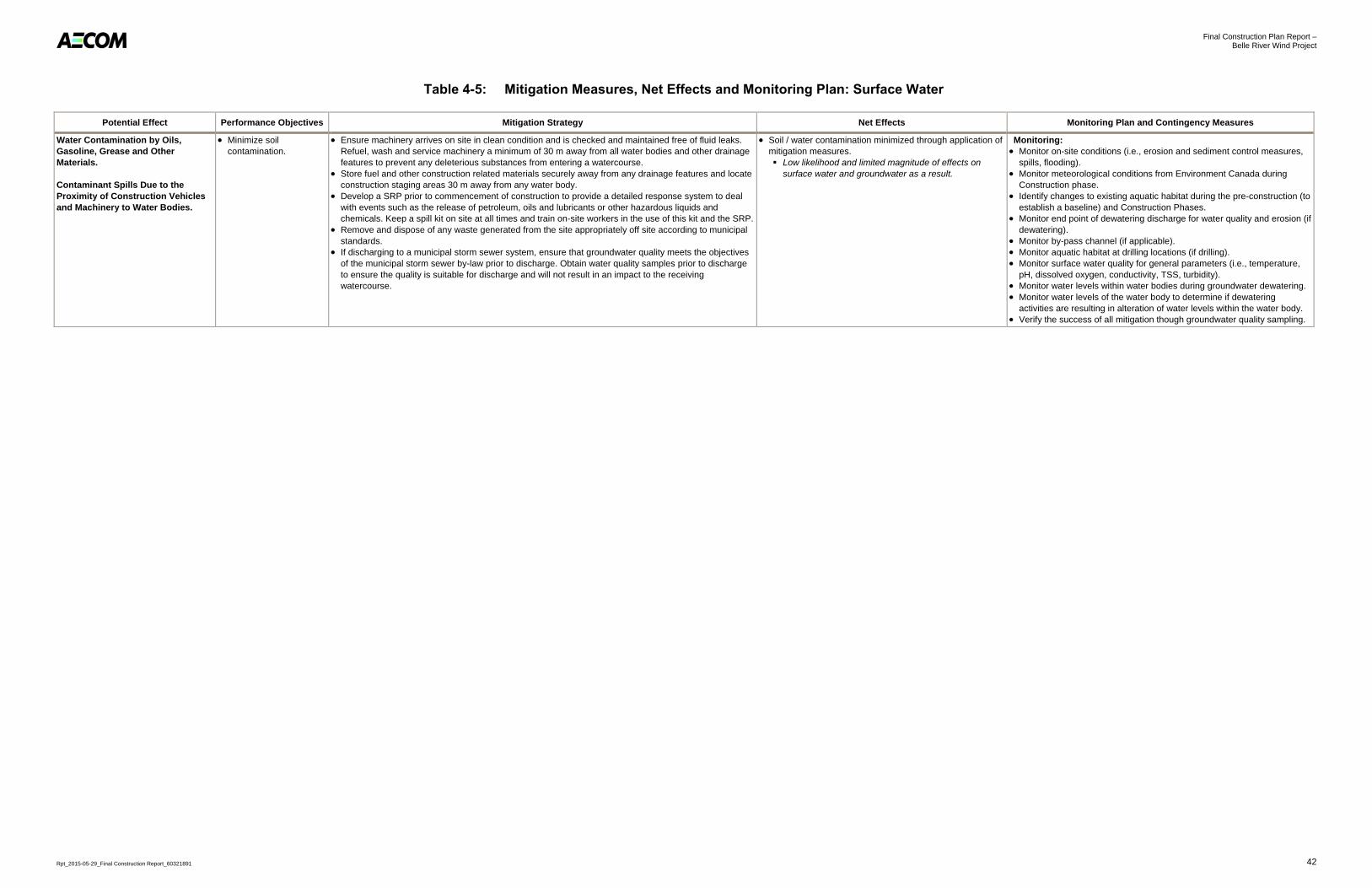
Final Construction Plan Report – Belle River Wind Project
Rpt_2015-05-29_Final Construction Report_60321891 42
Table 4-5: Mitigation Measures, Net Effects and Monitoring Plan: Surface Water
Potential Effect Performance Objectives Mitigation Strategy Net Effects Monitoring Plan and Contingency Measures
Water Contamination by Oils,
Gasoline, Grease and Other
Materials.
Contaminant Spills Due to the
Proximity of Construction Vehicles
and Machinery to Water Bodies.
Minimize soil
contamination.
Ensure machinery arrives on site in clean condition and is checked and maintained free of fluid leaks.
Refuel, wash and service machinery a minimum of 30 m away from all water bodies and other drainage
features to prevent any deleterious substances from entering a watercourse.
Store fuel and other construction related materials securely away from any drainage features and locate
construction staging areas 30 m away from any water body.
Develop a SRP prior to commencement of construction to provide a detailed response system to deal
with events such as the release of petroleum, oils and lubricants or other hazardous liquids and
chemicals. Keep a spill kit on site at all times and train on-site workers in the use of this kit and the SRP.
Remove and dispose of any waste generated from the site appropriately off site according to municipal
standards.
If discharging to a municipal storm sewer system, ensure that groundwater quality meets the objectives
of the municipal storm sewer by-law prior to discharge. Obtain water quality samples prior to discharge
to ensure the quality is suitable for discharge and will not result in an impact to the receiving
watercourse.
Soil / water contamination minimized through application of
mitigation measures.
Low likelihood and limited magnitude of effects on
surface water and groundwater as a result.
Monitoring:
Monitor on-site conditions (i.e., erosion and sediment control measures,
spills, flooding).
Monitor meteorological conditions from Environment Canada during
Construction phase.
Identify changes to existing aquatic habitat during the pre-construction (to
establish a baseline) and Construction Phases.
Monitor end point of dewatering discharge for water quality and erosion (if
dewatering).
Monitor by-pass channel (if applicable).
Monitor aquatic habitat at drilling locations (if drilling).
Monitor surface water quality for general parameters (i.e., temperature,
pH, dissolved oxygen, conductivity, TSS, turbidity).
Monitor water levels within water bodies during groundwater dewatering.
Monitor water levels of the water body to determine if dewatering
activities are resulting in alteration of water levels within the water body.
Verify the success of all mitigation though groundwater quality sampling.

Final Construction Plan Report – Belle River Wind Project
Rpt_2015-05-29_Final Construction Report_60321891 43
4.3.2 Impacts to Groundwater (including impacts related to Water Taking)
As described in the Technical Guide to Renewable Energy Approvals (MOECC, 2013), an important environmental
effect to consider is the potential for the Project to interfere with existing uses of a water resource. The following
section provides an overview of the Hydrogeological Assessment and Effects Assessment Report for the Belle River
Wind Project. For further details please refer to the Groundwater Supply Feasibility and Effects Desktop Assessment
in Appendix B of the Design and Operations Report.
4.3.2.1 Existing Conditions
The PSA is located within the Essex Clay Plain physiographic region, a sub-region of the St. Clair Clay Plains
physiographic region (Chapman and Putnam, 1984). The region is described as a low relief extensive clay plain that
slopes gently to the north, toward Lake St. Clair. The prominent soil type within the region is Brookston clay loam, a
dark-surfaced gleysolic soil that was developed under a swamp forest (Chapman and Putnam, 1984).
Currently, land use is dominated by general crop and livestock farming, which has been made possible by the
installation of dredged ditches and tile underdrains to provide satisfactory moisture conditions within the imperfectly
drained soils. Peat and muck accumulation, within areas of poorly drained soils, are also common within the region.
Ground surface topography within the PSA is characterized as having low relief, with minor undulations near river
valleys and the shoreline of Lake St. Clair.
Bedrock Geology
Thick successions of Middle Devonian aged Paleozoic sedimentary rocks subcrop beneath glacial cover across the
PSA. The PSA is primarily underlain by limestone of the Dundee Formation. The Dundee Formation can be
described as a brown and tan microcrystalline limestone with occasional sand grains and brown chert (Telford and
Russell, 1981). The average thickness of the Dundee Formation is 35 to 40 m (Strynatka, S., et al., 2007).
Overburden Geology
Bedrock within the PSA is overlain by thick overburden deposits consisting primarily of fine-textured glacial
sediments. Published geological mapping obtained from the Geological Survey of Canada, indicates that the PSA is
underlain by approximately 28 to 44 m of overburden sediments consisting primarily of fine-textured glacial and
proglacial deposits (Morris and Cousineau, 1994).
Groundwater Resources
Within the County of Essex, water for municipal supply is provided from surface water sources in the Great Lakes
system. There are no municipal supply wells currently providing water to the region (ERCA, 2014). Approximately 95
percent of the population within the County of Essex is served by municipal water. However, the remaining 5 percent
depend on groundwater as the primary water supply for properties outside the municipally serviced areas (ERCA,
2012). See Table 4-6 for a brief summary of recorded water well information in the PSA.
Table 4-6: Summary of MOECC Water Well Record Information
Primary Water Use Number of Well Records Well Depth (m) Primary Well Type
Commercial/Industrial 4 31.1 to 47.9 2 overburden, 2 bedrock
Domestic 26 25.9 to 44.2 4 overburden, 22 bedrock
Irrigation/Livestock 33 19.5 to 64.6 8 overburden, 25 bedrock
Monitoring/Test Hole 13 5.2 to 7.6 13 unknown
Public 3 29.6 to 39.6 0 overburden, 3 bedrock
Not Used 7 30.2 to 65.2 0 overburden, 4 bedrock, 3 unknown
Unknown 19 3.2 to 61.6 3 overburden, 8 bedrock, 8 unknown
Final Construction Plan Report – Belle River Wind Project
Rpt_2015-05-29_Final Construction Report_60321891 44
The location and depth of MOECC water well records gives some indication of the presence of viable groundwater
resources within the PSA. Approximately 61 percent of the wells within the PSA obtain their source water from the
bedrock aquifer. Only 16 percent of the MOECC water well records within the PSA were completed in overburden
sediments. This gives further evidence that the overburden is considered a poor groundwater resource.
Results of this desktop investigation indicate that the dominant soil type within the PSA is a clayey silt to silty clay till
and/or a fine-textured glaciolacustrine deposits, and that these materials do not readily transmit groundwater.
Therefore, turbine foundations excavated within these materials are not anticipated to require significant dewatering
during construction. Site specific geotechnical work has not yet been completed to confirm soil conditions at each
turbine site. Should turbines be excavated in coarser-grained materials (e.g., sand and/or gravel), below the water
table, dewatering requirements may exceed 50,000 L/day.
In conclusion, there is limited potential for groundwater takings to exceed 50,000 L/day at a turbine site, but is
dependent on the surficial material being excavated, the depth to groundwater (relative to the excavation extent),
and other hydrogeological characteristics that will be determined during geotechnical analysis. Should groundwater
dewatering rates be expected to exceed 50,000 L/day from a turbine foundation excavation, mitigation measures to
minimize the potential impact to groundwater resources will be applied.
Potential environmental impacts, mitigation measures, residual effects, and a monitoring plan associated with
potential effects to groundwater are described in Table 4-7. Once a final groundwater taking assessment is complete
based on geotechnical information, site specific effects may be assessed based on calculated groundwater
dewatering rates and ZOI.
4.4 Air, Odour and Dust Emissions
Excavation activities, construction vehicle traffic, temporary generator operation, and temporary exposure of soil
stockpiles have the potential to generate short-term localized dust emissions that could result in nuisance effects.
Operation of construction equipment as described in Section 3, in particular vehicles using diesel fuel, will result in
emissions including particulate, sulphur dioxide, nitrous oxides, volatile organic compounds, polyaromatic
hydrocarbons, and carbon dioxide. Furthermore, traffic delays caused by construction could result in increased
vehicle emissions in the PSA as vehicles travel slowly through construction zones. Air emissions will be highest
during land clearing and other activities that involve significant levels of material handling (e.g., aggregate laydown
for access road construction and preparation for the installation of underground collector lines).
No emissions of odours are anticipated.
Table 4-8 provides mitigation measures, net effects and the monitoring plan for each potential effect relating to
emissions to air.
4.5 Noise Emissions
The operation of heavy construction vehicles, potential blasting and temporary generators could also result in
nuisance noise at nearby residents or businesses and disturbance to local wildlife. Like air emissions, noise levels
will be highest during land clearing and other activities that involve significant levels of material handling (e.g.,
aggregate laydown for access road construction and preparation for the installation of underground collector lines).
Table 4-9 provides mitigation measures, net effects and the monitoring plan for each potential effect relating to noise.

Final Construction Plan Report – Belle River Wind Project
Rpt_2015-05-29_Final Construction Report_60321891 45
Table 4-7: Mitigation Measures, Net Effects and Monitoring Plan: Groundwater
Potential Effect Performance Objectives Mitigation Strategy Net Effects Monitoring Plan and Contingency
Measures
Temporary Reduction in
Groundwater Flow to Natural
Features (Water Bodies,
Watercourses and Wetlands)
during Groundwater
Dewatering Activities
Associated with Turbine
Foundation Construction.
Minimize reduction of
groundwater contribution to
near-by natural features.
Direct dewatering discharge to the
downgradient watercourse (following
sediment and erosion control practices)
to negate the potential that groundwater
drawdown will decrease baseflow into
streams and groundwater discharge into
wetlands.
Limit duration of dewatering to as short
a time frame as possible.
Implement groundwater cut-offs, where
practical, to limit groundwater taking
quantities.
Reduction in groundwater quantity and
quality minimized through application of
mitigation measures.
Low likelihood and negligible
magnitude of long term effects based
on the amount of dewatering required
and the duration of expected
dewatering activities.
Monitoring and Contingency Measures:
Should groundwater dewatering activities
be expected to exceed 50,000 L/day, the
following measures will be implemented:
Inlet pump head shall be surrounded
with clear stone and filter fabric.
The discharge shall be regulated at
such a rate that there is no flooding in
the receiving water body and that no
soil erosion is caused that impacts the
receiving water body.
Temporary Reduction in
Groundwater Quantity and
Quality to Existing
Groundwater Users (Private
Water Wells) during
Groundwater Dewatering
Activities Associated with
Turbine Foundation
Construction.
Minimize reduction of
groundwater quantity and
quality to existing
groundwater users.
Limit duration of dewatering to as short
a time frame as possible.
Implement groundwater cut-offs, where
practical, to limit groundwater taking
quantities.
Maintain a setback of 120 m from known
active residential groundwater supply
wells (private water wells), where
possible.
Reduction in groundwater quantity and
quality minimized through application of
mitigation measures.
Low likelihood and negligible
magnitude of long term effects based
on the amount of dewatering required
and the duration of expected
dewatering activities.
Monitoring and Contingency Measures:
Should groundwater dewatering activities
exceed 50,000 L/day and a private water
well becomes dry as a result of such
activities, a temporary potable water supply
will be provided to the property owner.
Contamination of Groundwater
Resources Due to Accidental
Spills or Releases of
Contaminants (i.e., Fuel,
Lubricating Oils and Other
Fluids) During the Refuelling,
Operation or Maintenance of
Construction Equipment.
Prevent contaminant
discharge to the
environment.
Develop a SRP and train staff on
procedures and protocols.
Refuel Project equipment and vehicles
on spill collection pads and/or in
designated areas.
Dispose of any waste material from
construction activities by authorized and
approved off-site vendors.
Groundwater contamination minimized
through application of mitigation
measures.
Low likelihood and limited magnitude
of effects on groundwater.
Monitoring:
Routine inspections performed by the
contractor of construction equipment for
leaks and spills.
Contingency Measures:
In the event of a spill all work will stop until
the spill is cleaned up.
Notify MOECC’s Spill Action Centre of any
leaks or spills.

Final Construction Plan Report – Belle River Wind Project
Rpt_2015-05-29_Final Construction Report_60321891 46
Table 4-8: Mitigation Measures, Net Effects and Monitoring Plan: Air, Odour and Dust
Potential Effect Performance Objectives Mitigation Strategy Net Effects Monitoring Plan and Contingency
Measures
Fugitive Dust and Vehicle
Emissions (including GHGs).
No persistent dust films
(observable build-up) on
nearby properties or
vegetation.
Limited release of air
emissions.
Implement a speed limit for construction
equipment and trucks on access roads.
Apply dust suppressants (e.g., water or
environmental friendly dust
suppressants) to unpaved areas at an
environmental acceptable rate to
minimize the release of dust.
Re-vegetate cleared areas as soon as
possible.
Install wind fences, as required.
Limit unnecessary idling of vehicles.
Increased dust and air emissions
minimized through application of
mitigation measures.
High likelihood of effects occurring;
however, any dust and air emissions
are short-term and localized so the
magnitude of such effects will be
limited.
Monitoring:
Monitor complaints through the Project
operations staff contact number
according to the Emergency Response
and Communications Plan (see Design
and Operations Report).
Contingency Measures:
Review of proposed mitigation
measures. Review of speed limit on access roads.
Reduction in Surface Water
Quality as a Result of Dust
Emissions.
No persistent dust films on
adjacent water bodies; no
measurable change in TSS.
Table 4-9: Mitigation Measures, Net Effects and Monitoring Plan: Noise
Potential Effect Performance Objectives Mitigation Strategy Net Effects Monitoring Plan and Contingency
Measures
Increased Noise Due to
Construction Activity.
Adherence to Town of
Lakeshore noise by-law no.
106-2007.
Schedule activities to comply with noise by-laws, where possible.
Ensure that construction equipment is
frequently maintained and kept in good
working condition.
Ensure that noise emissions from
construction equipment not exceed
guidelines specified in MOECC
publication NPC-115 and manufacturer
recommendations.
Implement construction speed limit on
unpaved roads.
High likelihood of increased noise during
construction; however, the effect will be
short-term, localized, and limited in
magnitude.
Monitoring:
Monitor complaints through the Project operations staff contact number according to the Emergency Response and Communications Plan (see Design and Operations Report).
Contingency Measures:
Repair equipment that is unable to meet
noise standards.
If noise complaints are received,
conduct an investigation to determine
the source of the problem.

Final Construction Plan Report – Belle River Wind Project
Rpt_2015-05-29_Final Construction Report_60321891 47
4.6 Impacts on Land Use and Infrastructure
There will be a temporary loss of agricultural land during construction and installation activities as a result of
temporary Project components, including crane pads, turbine laydown areas and the construction staging areas.
However, these areas will be small relative to the total land area within the PSA, and these lands will be returned to
pre-existing land use after construction and installation activities are completed, unless otherwise agreed upon with
the landowner. The construction of the Project will not result in the creation of access to previously inaccessible
areas as the Project is located in areas already cleared for agricultural uses.
The road capacity and local traffic may also be affected during construction related activities. The delivery of
construction equipment and Project infrastructure, and construction of new turbine access roads could result in a
temporary increase in slower moving traffic volume on local roads. Construction related activities next to or in road
easements could also result in temporary disruptions to the flow of traffic on some local roads. The changes in traffic
volume are expected to be minimal and no appreciable change to traffic flow is anticipated as a result of the Project.
Table 4-10 provides mitigation measures, net effects and the monitoring plan for each potential effect relating to
local interests, land use and infrastructure.

Final Construction Plan Report – Belle River Wind Project
Rpt_2015-05-29_Final Construction Report_60321891 48
Table 4-10: Mitigation Measures, Net Effects and Monitoring Plan: Land Use and Infrastructure
Potential Effect Performance Objectives Mitigation Strategy Net Effects Monitoring Plan and
Contingency Measures
Reduction in
Agricultural Land.
No significant economic
reduction in agricultural
yields on lots containing
Project Infrastructure.
Minimize length of access roads where
possible.
Consult with landowners to design access
roads to minimize impacts to existing land
use.
Compensate landowners on Project
Location as per land lease agreement.
Minor reduction in usable agricultural land. High likelihood of effect, however limited
magnitude due to size of overall footprint
within the entire PSA.
Monitoring and Contingency Measures:
No monitoring or contingency measures
required.
Damage to Local
Infrastructure.
Minimize damage to local
infrastructure.
Adhere to best practices regarding the
operation of construction equipment and
delivery of construction materials.
Undertake roads condition survey prior to
construction and post-construction.
Damage to local infrastructure minimized
through application of mitigation measures.
Moderate likelihood and magnitude of
effects occurring due to presence
oversize loads during delivery of turbine
components.
Monitoring:
Monitor complaints through the Project
operations staff contact number according
to the Emergency Response and
Communications Plan (see Design and
Operations Report).
Contingency Measures:
Return damaged infrastructure to original
condition (or better) where appropriate.
Increased Congestion
Due to Increase in
Truck Traffic and Short-
term Lane Closures on
Local Roads during
Delivery of Project
Components.
Minimize disturbances to
local traffic patterns.
Develop a traffic management plan for the
construction phase and submit to the
municipalities prior to construction.
Conduct a survey in conjunction with the
Town of Lakeshore and County of Essex to
determine if the roads and travel routes
within the PSA are capable of
accommodating the oversized vehicles and
heavy loads prior to the delivery of Project
components and equipment.
Notify the community in advance of
construction delivery schedules and install
signage to notify road users of construction
activity, where appropriate.
No significant adverse effects to local roads
and traffic are anticipated during
construction and installation activities
following the implementation of a traffic
management plan.
Monitoring:
The construction contractor will regularly
monitor and report to Belle River Wind on
the implementation of the traffic
management plan.
Contingency Measures:
To the extent possible, use alternate
component delivery routes.

Final Construction Plan Report – Belle River Wind Project
Rpt_2015-05-29_Final Construction Report_60321891 49
5. Summary and Conclusions
Desktop analysis and field work were undertaken to determine the potential effects to the various environmental and
social features during the construction and installation phase of the Project. Mitigation measures to manage these
potential effects have been identified and monitoring and contingency plans proposed to ensure effects are
minimized as outlined above.
The overall conclusion of this Construction Plan Report is that this Project can be constructed and installed
without any significant adverse net effects.

Final Construction Plan Report – Belle River Wind Project
Rpt_2015-05-29_Final Construction Report_60321891 50
6. References
Chapman, L.J. and D.F. Putnam, 1984:
The Physiography of Southern Ontario, Third Edition. Ontario Geological Survey, Special Volume: 2. 270p.
Accompanied by Map P.2715 (coloured), scale 1:600,000.
Essex Conservation Authority (ERCA), 2012:
County of Essex Source Protection Plan.
Essex Region Conservation Authority (ERCA), 2014:
Parks and Recreation – Conservation Areas. Accessed November 2014, Available:
http://erca.org/conservation-areas-events/conservation-areas/
Golder Associates Ltd., 2014a:
Stage 1 Archaeological Assessment. SP Belle River Wind LP, Belle River Wind Project, Various Lots and
Concessions, Geographic Townships of Maidstone, Rochester and Tilbury West, Essex County, Ontario.
Golder Associates Ltd., 2014b:
Heritage Impact Assessment. SP Belle River Wind LP, Belle River Wind Project, Various Lots and
Concessions, Former Townships of Maidstone, Rochester and Tilbury West, Now Town of Lakeshore,
Essex County, Ontario.
Golder Associates Ltd., 2015:
Stage 2 Archaeological Assessment. SP Belle River Wind LP, Belle River Wind Project, Various Lots and
Concessions, Geographic Townships of Maidstone, Rochester and Tilbury West, Essex County, Ontario.
Government of Ontario, 1990:
Ontario Water Resources Act. Ontario: Queen’s Printer.
Government of Ontario, 1990:
Ontario Heritage Act. Ontario: Queen’s Printer.
Government of Ontario, 2009:
Ontario Bill 150, Green Energy and Green Economy Act. May 14, 2009.
Government of Ontario, 2009:
Ontario Regulation 359/09. Ontario: Queen’s Printer.
Government of Ontario, 2009:
Ontario Regulation O. Reg. 9/06, Ontario: Queen’s Printer.
Morris, T.F. and G.R. Cousineau, 1994:
Drift Thickness, County of Essex Area (east half), southern Ontario: Ontario Geological Survey, Preliminary
Map P.3254, scale 1: 50,000.
Natural Resource Solutions Inc. (NRSI), 2015a:
Natural Heritage Assessment, Belle River Wind Project.
Natural Resource Solutions Inc. (NRSI), 2015b:
Water Body Report, Belle River Wind Project.

Final Construction Plan Report – Belle River Wind Project
Rpt_2015-05-29_Final Construction Report_60321891 51
Ontario Ministry of Natural Resources and Forestry (MNRF), 2012a:
Natural Heritage Assessment Guide for Renewable Energy Projects. Accessed January 2015. Available:
https://dr6j45jk9xcmk.cloudfront.net/documents/2716/stdprod-101413.pdf.
Ontario Ministry of Natural Resources and Forestry (MNRF), 2012b:
Sustainable Forest Licences. Ontario: Queen’s Printer. Accessed August 2012. Available:
http://www.mnr.gov.on.ca/en/Business/Forests/1ColumnSubPage/STDPROD_091540.html.
Ontario Ministry of the Environment and Climate Change (MOECC), 2012:
Ontario Regulation 359/09. Renewable Energy Approvals under Part V.0.1 of the Environmental Protection
Act. Consolidated May 2, 2014.
Ontario Ministry of the Environment and Climate Change (MOECC), 2013:
Draft Technical Guide to Renewable Energy Approvals. Accessed December 2014. Available:
https://www.ontario.ca/environment-and- energy/technical-guide-renewable-energy-approvals.
Ontario Ministry of Tourism, Culture and Sport (MTCS), 2011:
2011 Standards and Guidelines for Consultant Archaeologists. Ontario: Queen’s Printer. Accessed January
2015. Available: http://www.mtc.gov.on.ca/en/archaeology/archaeology_s_g.shtml.
Strynatka, S., T. Balakrishna, G. Harvey and P. Sarvas, 2007:
County of Essex Groundwater Resources Study: Ontario Geological Survey, Groundwater Resources Study
2, 81p.
Telford, P.G. and D.J. Russell, 1981:
Paleozoic Geology of the Windsor-Essex and Pelee Island Area, Southern Ontario; Ontario Geological
Survey Preliminary Map P.2396, Geological Series, Scales 1:250,000, 1:50,000. Geology 1977, 1980.
Town of Lakeshore, 2010:
Town of Lakeshore Official Plan. Approved by the Ontario Municipal Board November 2010.
Town of Lakeshore, 2014:
Town of Lakeshore Zoning By-law. Council adopted January 2010, Modified September 2014.


