
MINIMUM EQUIPMENT LIST
OPERATIONAL PROCEDURES
ATA 32 LANDING GEAR
AIRBUS A320
Doc. Ref :
Revision:
Date :
Page :
MNL-FL-007
Version : 0.91
20.Sep. 2013
1 of 33
CAA-01 ATA 32
Minimum Equipment List A320 Copyright © 2013 Edition 0
32-07-01A Brakes Temperature Indication on the WHEEL SD page
32-07-01B Ident.: MO-32-07-00009012.0003001 / 28 JUN 11
Applicable to: ALL
FLIGHT PREPARATION/LIMITATIONS
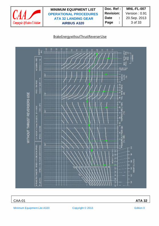
The brake energy graph and the brake cooling time table given hereafter permit to determine the
ground brake cooling time.
BRAKE ENERGY GRAPH
If MAX reverser thrust was selected for all reversers during the braking phase:
Enter the brake energy graph: WITH THRUST REVERSERS USE.
If MAX reverser thrust was NOT selected for all reversers during the braking phase:
Enter the brake energy graph: WITHOUT THRUST REVERSERS USE. Determination of the
brake energy accumulated during a REJECTED TAKEOFF (RTO):
‐ Enter with the aircraft takeoff weight (TOW) and with the rejected takeoff speed in kt IAS). ‐ Apply airport pressure altitude, temperature, wind and runway slope corrections.
Determination of the brake energy accumulated during a LANDING:
‐ Enter with the aircraft landing weight, and
‐ Enter with the touch down speed in kt IAS if the autobrake was selected and applied or with
the manual braking speed in kt IAS in the other cases.
‐ Apply airport pressure altitude, temperature, wind and runway slope corrections.
‐ Correct for brake setting with a preselected autobrake setting (LO, MED) or with MAX PEDAL
braking in the other cases.
Note: In the case of a dispatch with one brake inoperative (Refer to Item 32-42-01 Main
Wheel Brake or Refer to Item 32-42-02 Green System Brake), the brake energy
accumulated is increased by 34 %.

MINIMUM EQUIPMENT LIST
OPERATIONAL PROCEDURES
ATA 32 LANDING GEAR
AIRBUS A320
Doc. Ref :
Revision:
Date :
Page :
MNL-FL-007
Version : 0.91
20.Sep. 2013
2 of 33
CAA-01 ATA 32
Minimum Equipment List A320 Copyright © 2013 Edition 0
Brake Energy with Thrust Reverser Use
MINIMUM EQUIPMENT LIST
OPERATIONAL PROCEDURES
ATA 32 LANDING GEAR
AIRBUS A320
Doc. Ref :
Revision:
Date :
Page :
MNL-FL-007
Version : 0.91
20.Sep. 2013
3 of 33
CAA-01 ATA 32
Minimum Equipment List A320 Copyright © 2013 Edition 0
Brake Energy without Thrust Reverser Use

MINIMUM EQUIPMENT LIST
OPERATIONAL PROCEDURES
ATA 32 LANDING GEAR
AIRBUS A320
Doc. Ref :
Revision:
Date :
Page :
MNL-FL-007
Version : 0.91
20.Sep. 2013
4 of 33
CAA-01 ATA 32
Minimum Equipment List A320 Copyright © 2013 Edition 0
BRAKE COOLING TIME TABLE
Determination of the brake cooling time: EXAMPLE:
55 152 153 154 155 155 ====> TIME (min) WITHOUT BRAKE COOLING FAN
46 46 46 46 47 ====> TIME (min) WITH BRAKE COOLING FAN
If the Energy and the OAT are not given in the table, use the values given in the next adjacent
column/row.
For Example, with Energy = 78 MJ, and OAT = 15 °C, entering the next adjacent column/row
(Energy = 80 MJ, OAT = 20 °C) gives the following results: ‐ Without brake cooling fan: 189 min
‐ With brake cooling fan: 57 min
Enter the following table with the energy and the OAT to determine the ground brake cooling time.
GROUND BRAKE COOLING TIME (min)
ENERGY
(MJ)
0
OAT (°C) -50
0
0
-40
0
0
-30
0
0
-20
0
0
-10 0
0 0
0 0
10
0
0
20 30
0 0
0 0
40
0
0
50
0
0
55
0
0
5
0 0
0
0
0
0
0
0 0 0
0 0
0
0 0 0
0 0
0
0
0
0
0
0
10
15
0 0
31 9
0
0
35
10
0
0
38
11
4
1
42
12
9 14
3 4
45 48
13 14
19
6
51
15
23 27
7 8
54 57
16 17
31
9
60
18
35
10
62
19
37
11
64
19
20
59 18
62
19
65
19
67
20 70 72
21 22
74
22 77 79
23 24
81
24
83
25
84
25
25
81 24
83
25
85
25
87
26 89 91
27 27
92
28 94 96
28 29
98
29
99
30
100
30
30
35
98 29
11
2 34
99
30
113
34
101
30
115
34
103
31
116
35
104 106
31 32
117 119
35 36
107
32
120
36
109 110
33 33
121 123
36 37
112
34
124
37
113
34
125
38
114
34
126
38
40
124 37
125
37
126
38
127
38 129 130
39 39
131
39 132 133
40 40
134
40
135
41
136
41
45 134
40
135
41
136
41
137
41 139 140
42 42
141
42 142 143
42 43
144
43
145
43
145
44
50 144 43
145
43 146
44 146
44 147 148
44 45 149
45 150 151
45 45 152
46 153
46 153
46 GROUND BRAKE COOLING TIME (min)
ENERGY
(MJ) OAT (°C)
-50 -40 -30 -20 -10 0 10 20 30 40 50 55

MINIMUM EQUIPMENT LIST
OPERATIONAL PROCEDURES
ATA 32 LANDING GEAR
AIRBUS A320
Doc. Ref :
Revision:
Date :
Page :
MNL-FL-007
Version : 0.91
20.Sep. 2013
5 of 33
CAA-01 ATA 32
Minimum Equipment List A320 Copyright © 2013 Edition 0
55
60
152
46
160
48
153 154
46 46
160 161
48 48
155
46
162
49
155
47
163
49
156
47
164
49
157 158
47 47
164 165
49 50
159 160
48 48
166 167
50 50
160 161
48 48
167 168
50 50
65 167
50 167 168
50 50
169
51
170
51
170
51 171 172
51 52
172 173
52 52
174 174
52 52
70
75
173
52
179
54
174 174
52 52
180 180
54 54
175
53
181
54
176
53
182
54
176
53
182
55
177 178
53 53
183 183
55 55
178 179
54 54
184 185
55 55
180 180
54 54
185 186
56 56
80
85
185
55
190
57
185 186
56 56
190 191
57 57
186
56
191
57
187
56
192
58
188
56
193
58
188 189
56 57
193 194
58 58
189 190
57 57
194 195
58 58
190 191
57 57
195 196
59 59
90 195
58 195 196
59 59
196
59
197
59
197
59 198 198
59 60
199 199
60 60
200 200
60 60
95
100
199
60
204
61
200 200
60 60
204 205
61 61
201
60
205
62
201
60
206
62
202
61
206
62
202 203
61 61
207 207
62 62
203 204
61 61
208 208
62 62
204 205
61 61
208 209
63 63
105 208
62 208 209
63 63
209
63
210
63
210
63 211 211
63 63
212 212
63 64
212 213
64 64
110 212
64 212 213
64 64
213
64
214
64
214
64 215 215
64 64
215 216
65 65
216 216
65 65
115
120
216
65
219
66
216 217
65 65
220 220
66 66
217
65
221
66
217
65
221
66
218
65
221
66
218 219
65 66
222 222
67 67
219 219
66 66
222 223
67 67
220 220
66 66
223 223
67 67
A320 Messier/Goodrich - 03.01.05 - F476021.txt

MINIMUM EQUIPMENT LIST
OPERATIONAL PROCEDURES
ATA 32 LANDING GEAR
AIRBUS A320
Doc. Ref :
Revision:
Date :
Page :
MNL-FL-007
Version : 0.91
20.Sep. 2013
6 of 33
CAA-01 ATA 32
Minimum Equipment List A320 Copyright © 2013 Edition 0
AFTER ENGINE START
In the case of a false BRAKES HOT alert displayed on the EWD:
EMER CANC pb................................................................................................................. Press
Note: In the case of a false BRAKES HOT alert due to a faulty BTMU or a faulty BSCU, the
"T.O CONFIG NORMAL” line will not replace the "T.O CONFIG . . TEST" line in the T.O
MEMO. Consider normal configuration for takeoff provided that no alert was displayed
during the T.O CONFIG TEST.
CAUTION: The T.O CONFIG TEST pb must be maintained pressed to check that there is no
alert.
32-07-03A L/G Doors Position Indication on the WHEEL SD page
Ident.: MO-32-07-00009013.0001001 / 28 JUN 11
Applicable to: ALL
IN FLIGHT
MAX SPEED....................................................................................................... 250 kt or M 0.60
32-31-01A Landing Gear Control and Interface Unit (LGCIU)
Ident.: MO-32-31-00008975.0002001 / 28 JUN 11
Applicable to: ALL
DURING COCKPIT PREPARATION
HYDRAULIC/LGCIU/SYS2 (121VU Q35) C/B......................................................................PULL
The following table gives the consequences on the systems affected when the LGCIU 2 is
inoperative and above mentioned C/B is pulled.

MINIMUM EQUIPMENT LIST
OPERATIONAL PROCEDURES
ATA 32 LANDING GEAR
AIRBUS A320
Doc. Ref :
Revision:
Date :
Page :
MNL-FL-007
Version : 0.91
20.Sep. 2013
7 of 33
CAA-01 ATA 32
Minimum Equipment List A320 Copyright © 2013 Edition 0
SYSTEMS CONSEQUENCES PROCEDURE
AVNCS VENT
(on ground)
HYD
(on ground)
TPIS
• The system remains in closed circuit
configuration.
• The ground cooling system is
inoperative.
The PTU runs after the first engine start until
the second engine is started.
• Time limitations on ground for ELEC PWR
supply:
‐ OAT ≤ 43 °C: No Limitation
‐ 44 °C ≤ OAT ≤ 52 °C: 3 h
‐ OAT ≥ 53 °C: 30 min
• Check that the air conditioning system is
operative.
The BLUE ELEC PUMP FAULT light and the
YELLOW ENG 2 PUMP FAULT light come on
when engines are off.
The WHEEL TYRE LO PR alert threshold is
set to flight level.
ATC 2
(on ground)
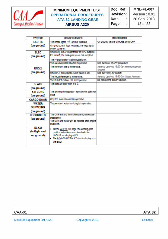
LIGHTS
The ATC 2 is not inhibited.
The strobe lights are not inhibited on
ground when set to AUTO.
On ground, set the ATC selector to SYS 1.
On ground, set the STROBE sw to OFF.
On ground, with flaps retracted, logo lights do
not come on.
The taxi light, the runway turn-off light, and the
takeoff light are inoperative on ground and in
flight.
ELEC
(on ground)
When only the APU generator or the GPU supplies the aircraft, the main galleys are not
supplied.
SYSTEMS CONSEQUENCES PROCEDURE
ENG 2
(on ground)
The FADEC supply is continuously on.
The automatic start abort is inoperative. Use the MAN START procedure.
The minimum idle is inoperative when
slats/flaps are extended. Ground
Refer to OpsProc 73-20-05A Minimum Idle on
When FLX TO is selected, MCT thrust is
set.
Use the TOGA for takeoff.
The thrust reverser is inoperative. Refer to OpsProc 78-30-01A Thrust Reverser
The BUMP function is inoperative. Do not use the BUMP function.

MINIMUM EQUIPMENT LIST
OPERATIONAL PROCEDURES
ATA 32 LANDING GEAR
AIRBUS A320
Doc. Ref :
Revision:
Date :
Page :
MNL-FL-007
Version : 0.91
20.Sep. 2013
8 of 33
CAA-01 ATA 32
Minimum Equipment List A320 Copyright © 2013 Edition 0
SLATS (on ground)
AIR COND (on
ground)
The slats are slow from 1 to 0.
Both air conditioning packs ram air inlet do
not
Close.
WING A ICE
(on ground)
On ground, when set to ON, the WING A
ICE valve do not close at the end of the test
sequence (30 s).
The WING A.ICE OPEN ON GND alert will be
displayed on the EWD.
ADIRU and AVNCS
VENT alert WATER
SERVICING (on
ground)
The horn and the light are inoperative.
The preselect water servicing is inoperative.
CARGO DOOR
(FWD and AFT)
RECORDERS (on
ground)
Only the manual control is operative.
The CVR test and the CVR erase functions
are inoperative. The CVR and the DFDR do
not stop after engine shutdown.
BRAKES (on
ground) AIRSTAIRS
The brakes cooling is inoperative.
The air stairs cannot be extended.
WEIGHT AND
BALANCE
SYSTEM ECAM
(in flight and on
ground)
The WBS is inoperative.
IN FLIGHT
In the case of loss of the LGCIU 1: AP and FD are lost. Maximum landing capability is CAT 1.
32-31-02A Landing Gear Retracting System
Ident.: MO-32-31-00008977.0001001 / 28 JUN 11
Applicable to: ALL
Refer to FCOM/PRO-SPO-25-FLIGHT WITH GEAR DOWN.

MINIMUM EQUIPMENT LIST
OPERATIONAL PROCEDURES
ATA 32 LANDING GEAR
AIRBUS A320
Doc. Ref :
Revision:
Date :
Page :
MNL-FL-007
Version : 0.91
20.Sep. 2013
9 of 33
CAA-01 ATA 32
Minimum Equipment List A320 Copyright © 2013 Edition 0
32-32-02A LGCIU 2 RH L/G Shock Absorber Proximity Detector
Ident.: MO-32-32-00008978.0002001 / 28 JUN 11
Applicable to: ALL
GENERAL INFORMATION SYSTEMS CONSEQUENCES PROCEDURES
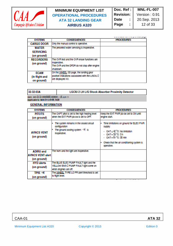
PITOTS
(on ground)
AVNCS VENT (on ground)
The F/O pitot is set to high heating level when the EXT PWR pb-sw is set to OFF.
• The system remains in the closed circuit
configuration.
• The ground cooling system is inoperative.
Keep the EXT PWR pb-sw set to ON until the
engine start.
• Time limitations on ground for ELEC PWR
supply:
‐ OAT ≤ 43 °C: No limitation
‐ OAT = 52 °C: 3 h
‐ OAT = 61 °C: 30 min
• Check that the air conditioning system is
operative. ADIRU and AVNCS
VENT alert (on
ground)
The horn and the light are inoperative.
HYD alerts
(on ground)
The BLUE ELEC PUMP FAULT light and the YELLOW ENG 2 PUMP FAULT light come on
when engines are off.
WING A/ICE
(on ground)
The wing anti-ice is not inhibited.
On ground, do not set the WING ANTI ICE pb-sw to ON for more that 30 s. If required, set
it to ON just before takeoff.
TPIS
(on ground)
The WHEEL TYRE LO PR alert threshold is set to flight level.
ATC 2
(on ground)
LIGHTS
(on ground)
The ATC 2 is not inhibited.
The strobe lights are not inhibited.
On ground, set the ATC selector to SYS 1.
On ground, set the STROBE sw to OFF.
On ground, with flaps retracted, the logo lights
do not come on.
ELEC When only the APU generator or GPU supplies
(on ground) the aircraft, the main galleys are not supplied.

MINIMUM EQUIPMENT LIST
OPERATIONAL PROCEDURES
ATA 32 LANDING GEAR
AIRBUS A320
Doc. Ref :
Revision:
Date :
Page :
MNL-FL-007
Version : 0.91
20.Sep. 2013
10 of 33
CAA-01 ATA 32
Minimum Equipment List A320 Copyright © 2013 Edition 0
SYSTEMS CONSEQUENCES PROCEDURES
The FADEC supply is continuously on.
ENG 2
(on ground)
The automatic start abort is inoperative. Use the MAN START procedure.
The minimum idle is inoperative.
When FLX TO is selected, MCT thrust is set.
Refer to OpsProc 73-20-05A Minimum Idle on
Ground
Use the TOGA for takeoff.
The thrust Reverser is inoperative. Refer to OpsProc 78-30-01A Thrust Reverser
The BUMP function is inoperative. Do not use the BUMP function.
SLATS (on ground) CARGO DOOROnly the
manual control is
operative.
(on ground)
The slats are slow from
1 to 0.
AIR COND (on ground) not close.
WATERThe preselect
water servicing is
inoperative.
SERVICING
(on ground)
The air conditioning pack 2 ram air inlet
does
AIRSTAIRS (on
ground) The CVR
test and the CVR erase
functions are
inoperative. The CVR
and the DFDR do not
stop after engine
shutdown.
The airstairs cannot be extended.
RECORDERS
ECAM position
indications associated
with the (in flight
and LGCIU 2 are
displayed XX.
on The L/G LGCIU 2 FAULT alert is displayed on the EWD.
• On the WHEEL SD page, the landing gear

MINIMUM EQUIPMENT LIST
OPERATIONAL PROCEDURES
ATA 32 LANDING GEAR
AIRBUS A320
Doc. Ref :
Revision:
Date :
Page :
MNL-FL-007
Version : 0.91
20.Sep. 2013
11 of 33
CAA-01 ATA 32
Minimum Equipment List A320 Copyright © 2013 Edition 0
32-32-03A LGCIU 2 LH L/G Shock Absorber Proximity Detector
Ident.: MO-32-32-00008988.0001001 / 28 JUN 11
Applicable to: MSN 0342
GENERAL INFORMATION
MINIMUM EQUIPMENT LIST
OPERATIONAL PROCEDURES
ATA 32 LANDING GEAR
AIRBUS A320
Doc. Ref :
Revision:
Date :
Page :
MNL-FL-007
Version : 0.91
20.Sep. 2013
12 of 33
CAA-01 ATA 32
Minimum Equipment List A320 Copyright © 2013 Edition 0
MINIMUM EQUIPMENT LIST
OPERATIONAL PROCEDURES
ATA 32 LANDING GEAR
AIRBUS A320
Doc. Ref :
Revision:
Date :
Page :
MNL-FL-007
Version : 0.91
20.Sep. 2013
13 of 33
CAA-01 ATA 32
Minimum Equipment List A320 Copyright © 2013 Edition 0

MINIMUM EQUIPMENT LIST
OPERATIONAL PROCEDURES
ATA 32 LANDING GEAR
AIRBUS A320
Doc. Ref :
Revision:
Date :
Page :
MNL-FL-007
Version : 0.91
20.Sep. 2013
14 of 33
CAA-01 ATA 32
Minimum Equipment List A320 Copyright © 2013 Edition 0

MINIMUM EQUIPMENT LIST
OPERATIONAL PROCEDURES
ATA 32 LANDING GEAR
AIRBUS A320
Doc. Ref :
Revision:
Date :
Page :
MNL-FL-007
Version : 0.91
20.Sep. 2013
15 of 33
CAA-01 ATA 32
Minimum Equipment List A320 Copyright © 2013 Edition 0

MINIMUM EQUIPMENT LIST
OPERATIONAL PROCEDURES
ATA 32 LANDING GEAR
AIRBUS A320
Doc. Ref :
Revision:
Date :
Page :
MNL-FL-007
Version : 0.91
20.Sep. 2013
16 of 33
CAA-01 ATA 32
Minimum Equipment List A320 Copyright © 2013 Edition 0
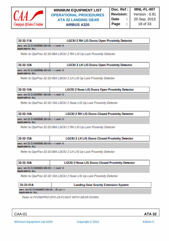
32-32-08A LGCIU 2 RH L/G Up Lock Proximity Detector
Ident.: MO-32-32-00008993.0004001 / 05 OCT 10
Applicable to: MSN 0112-0189
GENERAL INFORMATION SYSTEMS CONSEQUENCES PROCEDURES
ENG 2
(on ground)
REVERSER 2 is displayed in the INOP SYS
column on the STATUS SD page.
The thrust Reverser 2 is still operative.
The minimum idle on ground is inoperative
when slats/flaps are extended.
ECAM
(in flight and
on ground)
For WHEEL SD page and ECAM alert Refer to Item 32-31-01 Landing Gear Control and
Interface Unit (LGCIU) "ECAM" line.
32-32-08A LGCIU 2 RH L/G Up Lock Proximity Detector
Ident.: MO-32-32-00008993.0001001 / 05 OCT 10
Applicable to: MSN 0342
GENERAL INFORMATION
SYSTEMS CONSEQUENCES PROCEDURES
ECAM
(in flight and
on ground)
For WHEEL SD page and ECAM alert Refer to Item 32-31-01 Landing Gear Control and
Interface Unit (LGCIU) "ECAM" line.
32-32-09A LGCIU 2 LH L/G Up Lock Proximity Detector
Ident.: MO-32-32-00008994.0004001 / 17 SEP 10
Applicable to: MSN 0112-0189 SYSTEMS CONSEQUENCES PROCEDURES
REVERSER 2 is displayed in the INOP SYS ENG 2 column on the STATUS SD page.
(on ground) The minimum idle on ground is inoperative
when slats/flaps are extended.
The thrust Reverser 2 is still operative.
ECAM (in flight and
on ground)
For WHEEL SD page and ECAM alert Refer to Item 32-31-01 Landing Gear Control and
Interface Unit (LGCIU) "ECAM" line.

MINIMUM EQUIPMENT LIST
OPERATIONAL PROCEDURES
ATA 32 LANDING GEAR
AIRBUS A320
Doc. Ref :
Revision:
Date :
Page :
MNL-FL-007
Version : 0.91
20.Sep. 2013
17 of 33
CAA-01 ATA 32
Minimum Equipment List A320 Copyright © 2013 Edition 0
32-32-09A LGCIU 2 LH L/G Up Lock Proximity Detector
Ident.: MO-32-32-00008994.0001001 / 04 OCT 10
Applicable to: MSN 0342
32-32-10A LGCIU 2 Nose L/G Up Lock Proximity Detector
Ident.: MO-32-32-00009002.0004001 / 28 JUN 11
Applicable to: MSN 0112-0189, 0438
GENERAL INFORMATION SYSTEMS CONSEQUENCES PROCEDURES
REVERSER 2 is displayed in the INOP SYS
ENG 2 column on the STATUS SD page.
(on ground) The minimum idle on ground is inoperative
when slats/flaps are extended.
The thrust Reverser 2 is still operative.
ECAM For WHEEL SD page and ECAM alert Refer to Item 32-31-01 Landing Gear Control and
(in flight and Interface Unit (LGCIU) "ECAM" line.
on ground)
32-32-10A LGCIU 2 Nose L/G Up Lock Proximity Detector
Ident.: MO-32-32-00009002.0001001 / 04 OCT 10
Applicable to: MSN 0342
GENERAL INFORMATION
MINIMUM EQUIPMENT LIST
OPERATIONAL PROCEDURES
ATA 32 LANDING GEAR
AIRBUS A320
Doc. Ref :
Revision:
Date :
Page :
MNL-FL-007
Version : 0.91
20.Sep. 2013
18 of 33
CAA-01 ATA 32
Minimum Equipment List A320 Copyright © 2013 Edition 0

MINIMUM EQUIPMENT LIST
OPERATIONAL PROCEDURES
ATA 32 LANDING GEAR
AIRBUS A320
Doc. Ref :
Revision:
Date :
Page :
MNL-FL-007
Version : 0.91
20.Sep. 2013
19 of 33
CAA-01 ATA 32
Minimum Equipment List A320 Copyright © 2013 Edition 0
32-42-01A Main Wheel Brake
Ident.: MO-32-42-00009004.0229001 / 18 JUL 12 Applicable to: MSN 0112, 0342
FLIGHT PREPARATION/LIMITATIONS
Maximum landing capability is CAT 3 Single.
The following penalties may be used for takeoff and landing performance determination if no takeoff
and landing data (predetermined by using OCTOPUS program or other equivalent program with
present failure case) is available.
Takeoff performance computation:
The method explained hereafter allows the determination of the MTOW and associated
speeds (V1, VR, V2), by applying decrements on the MTOW and associated speeds
computed in normal conditions (i.e. all systems operative). The method is based on the use
of RTOW charts established at optimum V2/VS, optimum V1/VR, minimum V1.
WARNING ‐ Do not use this method with takeoff charts computed with other conditions.
‐ Do not use this method for takeoff with tailwind.
‐ Do not use this method for takeoff on wet or contaminated runways.
How to proceed ?
‐ Read, in 0 kt wind column of the takeoff chart computed in normal condition, the MTOW
and associated speeds (V1, VR, V2) corresponding to the actual temperature, even in the
case of headwind (the method does not take into account the headwind benefit on takeoff
performance).
‐ Apply the QNH and/or bleed corrections, if any, to determine the MTOW.
‐ Enter the following table to determine the MTOW and speed decrements.
‐ Applying these decrements, calculate the MTOW and associated speeds corresponding to
the actual temperature.
CAUTION Do not extrapolate below the shortest runway length provided by the table.

MINIMUM EQUIPMENT LIST
OPERATIONAL PROCEDURES
ATA 32 LANDING GEAR
AIRBUS A320
Doc. Ref :
Revision:
Date :
Page :
MNL-FL-007
Version : 0.91
20.Sep. 2013
20 of 33
CAA-01 ATA 32
Minimum Equipment List A320 Copyright © 2013 Edition 0
DECREMENTS (ΔW, ΔV1, ΔVR, ΔV2) WHEN ONE BRAKE IS INOPERATIVE
CONFIGURATION
RUNWAY 1+F 2 3
LENGTH (m) ΔW (kg/lb) ΔV1 ΔVR
(kt) (kt)
ΔV2
(kt)
ΔW (kg/lb) ΔV1
(kt)
ΔVR ΔV2
(kt) (kt)
ΔW (kg/lb) ΔV1
(kt)
ΔVR ΔV2
(kt) (kt)
1 500 2 600/5 800
2 000 2 800/6 200
7 2
7 2
2
2
2 600/5 800
2 600/5 800
7
7
2 2
2 2
2 400/5 300
2 600/5 800
7
7
2 2
2 2
2 500 4 000/8 900 12 4 4 3 800/8 400 10 4 4 2 600/5 800 11 5 5
DECREMENTS (ΔW, ΔV1, ΔVR, ΔV2) WHEN ONE BRAKE IS INOPERATIVE
CONFIGURATION
RUNWAY 1+F 2 3
LENGTH (m) ΔW (kg/lb) ΔV1
(kt)
ΔVR ΔV2
(kt) (kt)
ΔW (kg/lb) ΔV1
(kt)
ΔVR ΔV2
(kt) (kt)
ΔW (kg/lb) ΔV1
(kt)
ΔVR ΔV2
(kt) (kt)
3 000 6 800/15 000
3 500 8 200/18 100
18
16
8 8
12 12
5 800/12 800
7 000/15 500
18
17
8 8
13 13
4 400/9 800
4 400/9 800
22
20
10 10
14 14
4 000 and 8 200/18 100 above
17
15 15
6 600/14 600
18
17 17
5 200/11 500
20
17 17
If the actual TOW is lower than the MTOW calculated using above method:
The speeds determined without failure and associated with the actual TOW may be retained
provided that they are all lower than the speeds calculated using above method.
Check that the corrected V1 is equal to or above the minimum V1 value shown on the RTOW
chart (due to VMCG limitation).
If the corrected V1 is lower than the minimum V1: Take this last value as V1.
Further decrease the weight by 3 000 kg (6 600 lb) per kt difference between both values.
Check that the corrected VR is equal to or above the minimum VR value shown on the
RTOW chart (due to VMCA limitation).

MINIMUM EQUIPMENT LIST
OPERATIONAL PROCEDURES
ATA 32 LANDING GEAR
AIRBUS A320
Doc. Ref :
Revision:
Date :
Page :
MNL-FL-007
Version : 0.91
20.Sep. 2013
21 of 33
CAA-01 ATA 32
Minimum Equipment List A320 Copyright © 2013 Edition 0
If the corrected VR is lower than the minimum VR:
Takeoff cannot be performed using this method.
Check that the corrected V2 is equal to or above the minimum V2 value shown on the RTOW
chart (due to VMCA limitation).
If the corrected V2 is lower than the minimum V2:
Takeoff cannot be performed using this method.
Check that the corrected V2 is equal to or above the minimum V2 due to VMU limitation (see
Refer to FCOM/PER-TOF-TOD-25-20 MINIMUM V2 LIMITED BY VMU/VMCA (KT IAS)).
If the corrected V2 is lower than the minimum V2:
Takeoff cannot be performed using this method.
Landing performance computation: Multiply the landing distances by 1.25.
FOR TAKEOFF
The autobrake function, even if available, must not be used.
If the above method was used for takeoff performance computation:
Perform the takeoff using full thrust (TOGA).
In the case of engine failure at takeoff:
Retract the landing gear when positive climb.
Vibrations may occur during 1 or 2 min after the retraction of the landing gear.
If both engines are operative:
Keep the landing gear down for 1 min.
FOR LANDING
The autobrake function, even if available, must not be used.

MINIMUM EQUIPMENT LIST
OPERATIONAL PROCEDURES
ATA 32 LANDING GEAR
AIRBUS A320
Doc. Ref :
Revision:
Date :
Page :
MNL-FL-007
Version : 0.91
20.Sep. 2013
22 of 33
CAA-01 ATA 32
Minimum Equipment List A320 Copyright © 2013 Edition 0
32-42-01A Main Wheel Brake
Ident.: MO-32-42-00009004.0130001 / 18 JUL 12
Applicable to: MSN 0189
FLIGHT PREPARATION/LIMITATIONS
Maximum landing capability is CAT 3 Single.
The following penalties may be used for takeoff and landing performance determination if no takeoff
and landing data (predetermined by using OCTOPUS program or other equivalent program with
present failure case) is available.
Takeoff performance computation:
The method explained hereafter allows the determination of the MTOW and associated
speeds (V1, VR, V2), by applying decrements on the MTOW and associated speeds
computed in normal conditions (i.e. all systems operative). The method is based on the use
of RTOW charts established at optimum V2/VS, optimum V1/VR, minimum V1.
WARNING: ‐ Do not use this method with takeoff charts computed with other conditions.
‐ Do not use this method for takeoff with tailwind.
‐ Do not use this method for takeoff on wet or contaminated runways.
How to proceed ?
‐ Read, in 0 kt wind column of the takeoff chart computed in normal condition, the MTOW and
associated speeds (V1, VR, V2) corresponding to the actual temperature, even in the case of
headwind (the method does not take into account the headwind benefit on takeoff
performance).
‐ Apply the QNH and/or bleed corrections, if any, to determine the MTOW.
‐ Enter the following table to determine the MTOW and speed decrements.
‐ Applying these decrements, calculate the MTOW and associated speeds corresponding to
the actual temperature.
CAUTION: Do not extrapolate below the shortest runway length provided by the table.

MINIMUM EQUIPMENT LIST
OPERATIONAL PROCEDURES
ATA 32 LANDING GEAR
AIRBUS A320
Doc. Ref :
Revision:
Date :
Page :
MNL-FL-007
Version : 0.91
20.Sep. 2013
23 of 33
CAA-01 ATA 32
Minimum Equipment List A320 Copyright © 2013 Edition 0
DECREMENTS (ΔW, ΔV1, ΔVR, ΔV2) WHEN ONE BRAKE IS INOPERATIVE
CONFIGURATION
RUNWAY
1+F 2 3
LENGTH (m) ΔW (kg/lb) ΔV1 ΔVR
(kt) (kt)
ΔV2
(kt)
ΔW (kg/lb) ΔV1
(kt)
ΔVR ΔV2
(kt) (kt)
ΔW (kg/lb) ΔV1
(kt)
ΔVR ΔV2
(kt) (kt)
1 500 2 600/5 800
2 000 2 800/6 200
7 2
7 2
2
2
2 600/5 800
2 600/5 800
7
7
2 2
2 2
2 400/5 300
2 600/5 800
7
7
2 2
2 2
2 500 4 000/8 900 12 4 4 3 800/8 400 10 4 4 2 600/5 800 11 5 5
DECREMENTS (ΔW, ΔV1, ΔVR, ΔV2) WHEN ONE BRAKE IS INOPERATIVE
CONFIGURATION
RUNWAY 1+F 2 3
LENGTH (m) ΔW (kg/lb) ΔV1
(kt)
ΔVR ΔV2
(kt) (kt)
ΔW (kg/lb) ΔV1
(kt)
ΔVR ΔV2
(kt) (kt)
ΔW (kg/lb) ΔV1
(kt)
ΔVR ΔV2
(kt) (kt)
3 000 6 800/15 000
3 500 8 200/18 100
18
16
8 8
12 12
5 800/12 800
7 000/15 500
18
17
8 8
13 13
4 400/9 800
4 400/9 800
22
20
10 10
14 14
4 000 and 8 200/18 100
above
17
15 15
6 600/14 600
18
17 17
5 200/11 500
20
17 17
If the actual TOW is lower than the MTOW calculated using above method:
The speeds determined without failure and associated with the actual TOW may be retained
provided that they are all lower than the speeds calculated using above method.
Check that the corrected V1 is equal to or above the minimum V1 value shown on the RTOW chart
(due to VMCG limitation).
If the corrected V1 is lower than the minimum V1: Take this last value as V1.
Further decrease the weight by 3 000 kg (6 600 lb) per kt difference between both values. Check
that the corrected VR is equal to or above the minimum VR value shown on the RTOW chart
(due to VMCA limitation).
If the corrected VR is lower than the minimum VR:
Takeoff cannot be performed using this method.

MINIMUM EQUIPMENT LIST
OPERATIONAL PROCEDURES
ATA 32 LANDING GEAR
AIRBUS A320
Doc. Ref :
Revision:
Date :
Page :
MNL-FL-007
Version : 0.91
20.Sep. 2013
24 of 33
CAA-01 ATA 32
Minimum Equipment List A320 Copyright © 2013 Edition 0
Check that the corrected V2 is equal to or above the minimum V2 value shown on the RTOW chart
(due to VMCA limitation).
If the corrected V2 is lower than the minimum V2:
Takeoff cannot be performed using this method.
Check that the corrected V2 is equal to or above the minimum V2 due to VMU limitation (Refer to
FCOM/PER-TOF-TOD-25-20 MINIMUM V2 LIMITED BY VMU/VMCA (KT IAS)).
If the corrected V2 is lower than the minimum V2:
Takeoff cannot be performed using this method.
Landing performance computation: Multiply the landing distances by 1.25.
FOR TAKEOFF
The autobrake function, even if available, must not be used.
If the above method was used for takeoff performance computation:
Perform the takeoff using full thrust (TOGA).
In the case of engine failure at takeoff:
Retract the landing gear when positive climb.
Vibrations may occur during 1 or 2 min after the retraction of the landing gear.
If both engines are operative:
Keep the landing gear down for 1 min.
FOR LANDING
The autobrake function, even if available, must not be used.

MINIMUM EQUIPMENT LIST
OPERATIONAL PROCEDURES
ATA 32 LANDING GEAR
AIRBUS A320
Doc. Ref :
Revision:
Date :
Page :
MNL-FL-007
Version : 0.91
20.Sep. 2013
25 of 33
CAA-01 ATA 32
Minimum Equipment List A320 Copyright © 2013 Edition 0
32-42-01A Main Wheel Brake
Ident.: MO-32-42-00009004.0130001 / 18 JUL 12 Applicable to: MSN 0189
FLIGHT PREPARATION/LIMITATIONS
Maximum landing capability is CAT 3 Single.
The following penalties may be used for takeoff and landing performance determination if no takeoff
and landing data (predetermined by using OCTOPUS program or other equivalent program with
present failure case) is available.
Takeoff performance computation:
The method explained hereafter allows the determination of the MTOW and associated
speeds (V1, VR, V2), by applying decrements on the MTOW and associated speeds
computed in normal conditions (i.e. all systems operative). The method is based on the use
of RTOW charts established at optimum V2/VS, optimum V1/VR, minimum V1.
WARNING: ‐ Do not use this method with takeoff charts computed with other conditions.
‐ Do not use this method for takeoff with tailwind.
‐ Do not use this method for takeoff on wet or contaminated runways.
How to proceed ?
‐ Read, in 0 kt wind column of the takeoff chart computed in normal condition, the MTOW
and associated speeds (V1, VR, V2) corresponding to the actual temperature, even in the
case of headwind (the method does not take into account the headwind benefit on takeoff
performance).
‐ Apply the QNH and/or bleed corrections, if any, to determine the MTOW.
‐ Enter the following table to determine the MTOW and speed decrements.
‐ Applying these decrements, calculate the MTOW and associated speeds corresponding to
the actual temperature.
CAUTION: Do not extrapolate below the shortest runway length provided by the table.

MINIMUM EQUIPMENT LIST
OPERATIONAL PROCEDURES
ATA 32 LANDING GEAR
AIRBUS A320
Doc. Ref :
Revision:
Date :
Page :
MNL-FL-007
Version : 0.91
20.Sep. 2013
26 of 33
CAA-01 ATA 32
Minimum Equipment List A320 Copyright © 2013 Edition 0
DECREMENTS (ΔW, ΔV1, ΔVR, ΔV2) WHEN ONE BRAKE IS INOPERATIVE
CONFIGURATION
RUNWAY 1+F 2 3
LENGTH (m) ΔW (kg/lb) ΔV1
(kt)
ΔVR ΔV2
(kt) (kt)
ΔW (kg/lb) ΔV1
(kt)
ΔVR ΔV2
(kt) (kt)
ΔW (kg/lb) ΔV1
(kt)
ΔVR ΔV2
(kt) (kt)
1 500 3 000/6 700
2 000 3 200/7 100
7
8
3 3
3 3
2 600/5 800
3 000/6 700
7
7
2 2
2 2
2 400/5 300
3 000/6 700
7
7
2 2
3 3
2 500 5 200/11 500 14 4 4 4 800/10 600 13 5 5 4 600/10 200 13 5 5
3 000 9 400/20 800 16 9 9 5 600/12 400 18 6 6 7 000/15 500 19 11 11
3 500 9 200/20 300 16 11 11 7 500/16 600 16 11 11 8 000/17 700 18 16 16
4 000 and 9 500/21 000 above
15
13 13 7 600/16 800 16
15 15 8 600/19 000 16
14 14
If the actual TOW is lower than the MTOW calculated using above method:
The speeds determined without failure and associated with the actual TOW may be retained
provided that they are all lower than the speeds calculated using above method.
Check that the corrected V1 is equal to or above the minimum V1 value shown on the RTOW
chart (due to VMCG limitation).
If the corrected V1 is lower than the minimum V1: Take this last value as V1.
Further decrease the weight by 3 000 kg (6 600 lb) per kt difference between both values.
Check that the corrected VR is equal to or above the minimum VR value shown on the RTOW
chart (due to VMCA limitation).
If the corrected VR is lower than the minimum VR:
Takeoff cannot be performed using this method.
Check that the corrected V2 is equal to or above the minimum V2 value shown on the RTOW
chart (due to VMCA limitation).
If the corrected V2 is lower than the minimum V2:

MINIMUM EQUIPMENT LIST
OPERATIONAL PROCEDURES
ATA 32 LANDING GEAR
AIRBUS A320
Doc. Ref :
Revision:
Date :
Page :
MNL-FL-007
Version : 0.91
20.Sep. 2013
27 of 33
CAA-01 ATA 32
Minimum Equipment List A320 Copyright © 2013 Edition 0
Takeoff cannot be performed using this method.
Check that the corrected V2 is equal to or above the minimum V2 due to VMU limitation (Refer to
FCOM/PER-TOF-TOD-25-20 MINIMUM V2 LIMITED BY VMU/VMCA (KT IAS)).
If the corrected V2 is lower than the minimum V2:
Takeoff cannot be performed using this method.
Landing performance computation: Multiply the landing distances by 1.25.
FOR TAKEOFF
The autobrake function, even if available, must not be used.
If the above method was used for takeoff performance computation:
Perform the takeoff using full thrust (TOGA).
In the case of engine failure at takeoff:
Retract the landing gear when positive climb.
Vibrations may occur during 1 or 2 min after the retraction of the landing gear.
If both engines are operative: Keep the landing gear down for 1 min.
FOR LANDING
The autobrake function, even if available, must not be used.
32-42-02A Green System Brake
Ident.: MO-32-42-00009005.0001001 / 11 MAR 10
Applicable to: ALL
Refer to OpsProc 32-42-01A Main Wheel Brake.

MINIMUM EQUIPMENT LIST
OPERATIONAL PROCEDURES
ATA 32 LANDING GEAR
AIRBUS A320
Doc. Ref :
Revision:
Date :
Page :
MNL-FL-007
Version : 0.91
20.Sep. 2013
28 of 33
CAA-01 ATA 32
Minimum Equipment List A320 Copyright © 2013 Edition 0
32-42-05A AUTO/BRK Function
Ident.: MO-32-42-00009006.0001001 / 11 MAR 10
Applicable to: ALL
FLIGHT PREPARATION/LIMITATIONS
Maximum landing capability is CAT 3 SINGLE.
BEFORE TAKEOFF
When T.O MEMO is displayed on the EWD, disregard the line:
AUTO BRK....................................................................................................................... MAX (blue)
32-47-01A Brake Temperature Monitoring Unit (BTMU)
Ident.: MO-32-47-00009008.0001001 / 28 JUN 11
Applicable to: ALL
DURING PRELIMINARY COCKPIT PREPARATION
HYDRAULIC/BRK/TEMP/DET/UNIT (121VU M26 or M37) C/B................................................PULL
Determine brake cooling time (Refer to OpsProc 32-07-01A (B) Brakes Temperature Indication on
the WHEEL SD page).
32-51-01A Nose Wheel Steering Control System
Ident.: MO-32-51-00009009.0001001 / 28 JUN 11
Applicable to: MSN 0342
GENERAL INFORMATION
The electrical and hydraulic control of NWS is inoperative. Do not reset the WHEEL N.W. STEER
FAULT alert with A/SKID & N/W STRG selector. The WHEEL N.W. STEER FAULT alert indicates
that no hydraulic pressure is applied on the NWS actuator.
FLIGHT PREPARATION/LIMITATIONS
Dispatch is not permitted from (or to) contaminated runways. Maximum crosswind component for
takeoff and landing: 20 kt. Maximum landing capability is CAT 3 SINGLE.
Note: the automatic roll out is not permitted (Refer to QRH/OPS Required Equipment for
CAT2 and CAT3).

MINIMUM EQUIPMENT LIST
OPERATIONAL PROCEDURES
ATA 32 LANDING GEAR
AIRBUS A320
Doc. Ref :
Revision:
Date :
Page :
MNL-FL-007
Version : 0.91
20.Sep. 2013
29 of 33
CAA-01 ATA 32
Minimum Equipment List A320 Copyright © 2013 Edition 0
For operations with crosswind component above 5 kt:
Reduce maximum takeoff performance limiting weight by 1 000 kg (2 200 lb)
DURING TAXI
Taxiing Procedure:
‐ Avoid high thrust settings, taxi speed limited to 20 kt.
‐ Check brakes temperature (if available) before takeoff.
If necessary, set the BRAKES FAN pb-sw to ON.
‐ Minimum speed of 5 kt is required to initiate a turn.
‐ Apply asymmetrical thrust in straight taxi to compensate crosswind and differential braking for taxi
and line up as required.
‐ Avoid sharp turns and use maximum width of the runway.
‐ Do not apply too high asymmetrical thrust to avoid that nose landing gear get stuck to full travel
(90 °) (in that case release the aircraft by towing).
FOR TAKEOFF
In the case of crosswind component above 5 kt:
‐ Set full nose down elevator till 80 kt regardless of the aircraft loading.
‐ Apply N1 = 50 % on the brakes
‐ Release the brakes, and smoothly apply takeoff power
‐ Use asymmetric braking, if required, to keep on runway center-line until directional control is
available by use of rudder.
‐ Release stick progressively to reach neutral at about 100 kt.
FOR LANDING
Do not use autobrake for landing.
In the case of crosswind component above 5 kt:
‐ Aircraft lateral control is achieved with the rudder until slowing to approximately 50 kt IAS.
‐ Upon reaching 50 kt IAS use differential braking to achieve taxi speed as required.
AFTER LANDING
Disengage AP at touchdown when autoland is performed.

MINIMUM EQUIPMENT LIST
OPERATIONAL PROCEDURES
ATA 32 LANDING GEAR
AIRBUS A320
Doc. Ref :
Revision:
Date :
Page :
MNL-FL-007
Version : 0.91
20.Sep. 2013
30 of 33
CAA-01 ATA 32
Minimum Equipment List A320 Copyright © 2013 Edition 0
32-51-01A Nose Wheel Steering Control System
Ident.: MO-32-51-00009009.0006001 / 28 JUN 11
Applicable to: MSN 0112-0189
GENERAL INFORMATION
The electrical and hydraulic control of NWS is inoperative. Do not reset the WHEEL N/W STRG
FAULT alert with A/SKID & N/W STRG selector. The WHEEL N/W STRG FAULT alert indicates
that no hydraulic pressure is applied on the NWS actuator.
FLIGHT PREPARATION/LIMITATIONS
Dispatch is not permitted from (or to) contaminated runways.
Maximum crosswind component for takeoff and landing: 20 kt.
Maximum landing capability is CAT 3 SINGLE.
Note: the automatic roll out is not permitted (Refer to QRH/OPS Required Equipment for
CAT2 and CAT3).
For operations with crosswind component above 5 kt:
Reduce maximum takeoff performance limiting weight by 1 000 kg (2 200 lb).
DURING TAXI
Taxiing Procedure:
‐ Avoid high thrust settings, taxi speed limited to 20 kt.
‐ Check brakes temperature (if available) before takeoff.
If necessary, set the BRAKES FAN pb-sw to ON.
‐ Minimum speed of 5 kt is required to initiate a turn.
‐ Apply asymmetrical thrust in straight taxi to compensate crosswind and differential braking
for taxi and line up as required.
‐ Avoid sharp turns and use maximum width of the runway.
‐ Do not apply too high asymmetrical thrust to avoid that nose landing gear get stuck to full
travel (90 °) (in that case release the aircraft by towing).
FOR TAKEOFF
In the case of crosswind component above 5 kt:
‐ Set full nose down elevator till 80 kt regardless of the aircraft loading.
MINIMUM EQUIPMENT LIST
OPERATIONAL PROCEDURES
ATA 32 LANDING GEAR
AIRBUS A320
Doc. Ref :
Revision:
Date :
Page :
MNL-FL-007
Version : 0.91
20.Sep. 2013
31 of 33
CAA-01 ATA 32
Minimum Equipment List A320 Copyright © 2013 Edition 0
‐ Apply N1 = 50 % on the brakes
‐ Release the brakes, and smoothly apply takeoff power
‐ Use asymmetric braking, if required, to keep on runway center-line until directional control is
available by use of rudder.
‐ Release stick progressively to reach neutral at about 100 kt.
FOR LANDING
Do not use autobrake for landing.
In the case of crosswind component above 5 kt:
‐ Aircraft lateral control is achieved with the rudder until slowing to approximately 50 kt IAS.
‐ Upon reaching 50 kt IAS use differential braking to achieve taxi speed as required.
AFTER LANDING
Disengage AP at touchdown when autoland is performed.
32-51-02A Rudder PEDALS DISC pb
Ident.: MO-32-51-00012799.0001001 / 17 SEP 10
Applicable to: ALL
The purpose of the procedure is to explain how to perform the flight control check with one or both
PEDALS DISC pb failed in the released position. GENERAL INFORMATION
When the disconnection is not possible on one side:
The flight control check can be performed on the operative side.
When the disconnection is not possible on both sides:
The flight control check must be performed while aircraft is stopped.
Note: it is not necessary to set the A/SKID & N/W STRG sw to OFF.
32-51-03A NWS Electrical Deactivation Box (towing mode is not
available when the lever is in the TOWING position)
Ident.: MO-32-51-00009010.0001001 / 17 SEP 10
Applicable to: ALL
BEFORE CONVENTIONAL OR TOWLESS PUSHBACK
A/SKID & N/W STRG selector.................................................................................................... OFF

MINIMUM EQUIPMENT LIST
OPERATIONAL PROCEDURES
ATA 32 LANDING GEAR
AIRBUS A320
Doc. Ref :
Revision:
Date :
Page :
MNL-FL-007
Version : 0.91
20.Sep. 2013
32 of 33
CAA-01 ATA 32
Minimum Equipment List A320 Copyright © 2013 Edition 0
AFTER PUSHBACK
A/SKID & N/W STRG selector...................................................................................................... ON
32-51-03B NWS Electrical Deactivation Box (NWS Electrical Deactivation
Box deactivated)
Ident.: MO-32-51-00012592.0001001 / 17 SEP 10
Applicable to: ALL
BEFORE CONVENTIONAL OR TOWLESS PUSHBACK
A/SKID & N/W STRG selector.................................................................................................... OFF
As a result of the NWS electrical box deactivation, the parking brake light on that box will not be
available.
The parking brake setting must be verbally confirmed between the flight crew and the
ground personnel before pushback.
AFTER PUSHBACK
A/SKID & N/W STRG selector...................................................................................................... ON
32-51-04A PARKING BRAKE light on the NWS Electrical Deactivation Box
Ident.: MO-32-51-00009011.0001001 / 17 SEP 10
Applicable to: ALL
BEFORE PUSHBACK
The parking brake setting must be verbally confirmed between the flight crew and the ground
personnel.

MINIMUM EQUIPMENT LIST
OPERATIONAL PROCEDURES
ATA 32 LANDING GEAR
AIRBUS A320
Doc. Ref :
Revision:
Date :
Page :
MNL-FL-007
Version : 0.91
20.Sep. 2013
33 of 33
CAA-01 ATA 32
Minimum Equipment List A320 Copyright © 2013 Edition 0
INTENTIONALLY LEFT BLANK


