
Folie 2 © Fraunhofer UMSICHT
Fuel flexibility in gasification: experiences and challenges
Tim Schulzke, Group Manager Thermochemical Processes and Hydrocarbons

© Fraunhofer
Outline
1. Fraunhofer-Gesellschaft and Fraunhofer UMSICHT
2. Fundamentals of solid fuel gasification
3. Gasification plants at Fraunhofer UMSICHT
4. Bandwidth of fuels used
5. Challenges for future plants
6. Summary

© Fraunhofer
Outline
1. Fraunhofer-Gesellschaft and Fraunhofer UMSICHT
2. Fundamentals of solid fuel gasification
3. Gasification plants at Fraunhofer UMSICHT
4. Bandwidth of fuels used
5. Challenges for future plants
6. Summary
Folie 5 © Fraunhofer UMSICHT
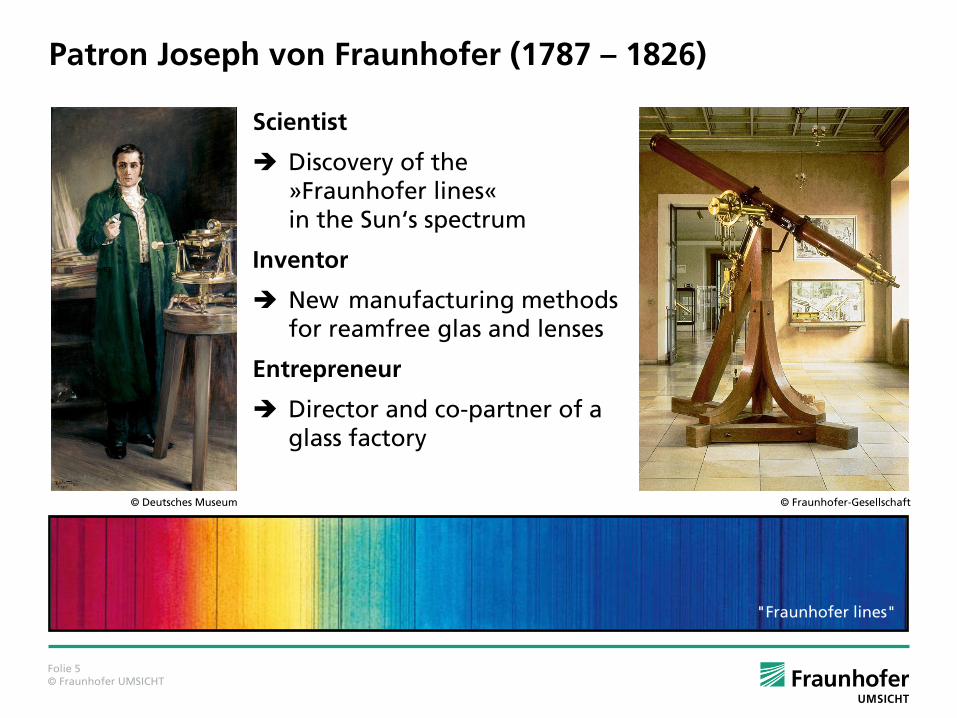
Scientist
Discovery of the »Fraunhofer lines« in the Sun‘s spectrum
Inventor
New manufacturing methods for reamfree glas and lenses
Entrepreneur
Director and co-partner of a glass factory
Patron Joseph von Fraunhofer (1787 – 1826)
© Fraunhofer-Gesellschaft
"Fraunhofer lines"
© Deutsches Museum

Folie 6 © Fraunhofer UMSICHT
Karlsruhe
Darmstadt
Würzburg
Jena
Stuttgart
Duisburg
Oberhausen Dortmund
München
Saarbrücken
St. Ingbert
Magdeburg
Halle
Dresden
Leipzig
Ilmenau
Cottbus
Braunschweig
Berlin
Potsdam
Teltow
Aachen
Schmallenberg
Sankt Augustin
Erlangen
Nürnberg
Freising
Holzkirchen
Pfinztal
Freiburg
Efringen-Kirchen
Rostock
Itzehoe
Hannover
Bremen
Euskirchen Chemnitz
Wertheim Kaiserslautern
Paderborn
Schkopau
Lübeck
Sulzbach-Rosenberg
Institute branch
The Fraunhofer-Gesellschaft
67 institutes and independent research facilities
€ 2 bn research funds
€ 1.7 bn contract research
More than 23 000 employees (m/f)1
40 facilities in Germany
13 institutes in North Rhine- Westphalia
4 institutes in the Ruhr area
more information under:
www.fraunhofer.de/en.html
1 23 236 (m/f) as per 12-31-2013 including fixed-term contracts of less than 18 months.
Folie 7 © Fraunhofer UMSICHT
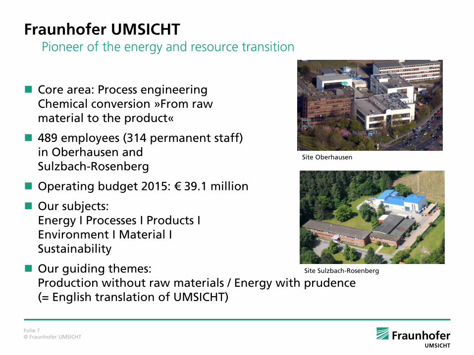
Fraunhofer UMSICHT Pioneer of the energy and resource transition
Core area: Process engineering Chemical conversion »From raw material to the product«
489 employees (314 permanent staff) in Oberhausen and Sulzbach-Rosenberg
Operating budget 2015: € 39.1 million
Our subjects: Energy I Processes I Products I Environment I Material I Sustainability
Our guiding themes: Production without raw materials / Energy with prudence (= English translation of UMSICHT)
Site Oberhausen
Site Sulzbach-Rosenberg

© Fraunhofer
Outline
1. Fraunhofer-Gesellschaft and Fraunhofer UMSICHT
2. Fundamentals of solid fuel gasification
3. Gasification plants at Fraunhofer UMSICHT
4. Bandwidth of fuels used
5. Challenges for future plants
6. Summary

Folie 9 © Fraunhofer UMSICHT
Process of Gas Generation from Solid Fuels
The conversion of solid fuels into gaseous energy carrier by means of gasification requires a certain effort, which can be distributed over the major process steps
Fuel Conditioning,
Gasification Reactor and
Gas Conditioning
with varying emphasis.
Solid fuel fuel
conditioning Gasifier
gas conditioning
Utilization

Folie 10 © Fraunhofer UMSICHT
Gasification - Classification by Reactor Typ
countercurrent cocurrent
bubbling
fluidized bed
circulating
fluidized bed
fixed bed gasifier fluidized bed gasifier
Gas Fuel
Air Ash
Gas
Ash
Fuel
Air
Fuel
secondary
air
Gas
Ash
Siphon
air
primary
air
Fuel
Air
Gas Ash
Air
fluifized bed
freeboard
Drying zone
Pyrolysis zone
Reduction zone
Oxidation zone
Not shown: entrained flow gasifier (suitable only for very large capacity)
Folie 11 © Fraunhofer UMSICHT
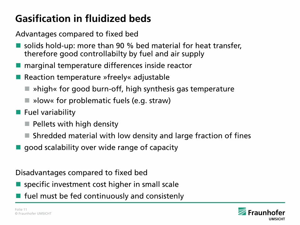
Gasification in fluidized beds
Advantages compared to fixed bed
solids hold-up: more than 90 % bed material for heat transfer, therefore good controllabilty by fuel and air supply
marginal temperature differences inside reactor
Reaction temperature »freely« adjustable
»high« for good burn-off, high synthesis gas temperature
»low« for problematic fuels (e.g. straw)
Fuel variability
Pellets with high density
Shredded material with low density and large fraction of fines
good scalability over wide range of capacity
Disadvantages compared to fixed bed
specific investment cost higher in small scale
fuel must be fed continuously and consistenly
Folie 12 © Fraunhofer UMSICHT
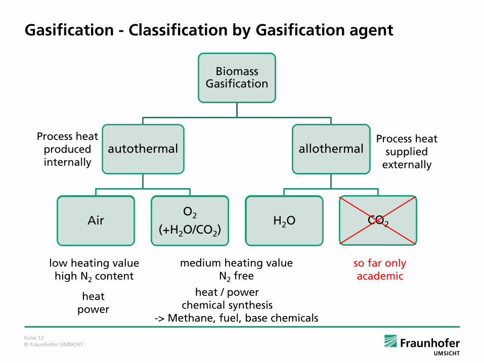
Gasification - Classification by Gasification agent
Biomass Gasification
autothermal
Air O2
(+H2O/CO2)
allothermal
H2O CO2
low heating value high N2 content
medium heating value N2 free
so far only academic
heat power
heat / power chemical synthesis -> Methane, fuel, base chemicals
Process heat produced internally
Process heat supplied
externally

Folie 13 © Fraunhofer UMSICHT
Gas composition– Comparison Air/Steam
Gasification with Air Gasification wth Steam
UMSICHT CFB ( 900 °C) Güssing FICFB* ( 840 °C)
N2
43 %
H2O
10 % CO2
13 %
CO
16 % H2
14 %
CH4
4 %
Tar (including Benzene)
< 0.5 %
H2O
35 %
CO2
13.7 %
CO
15.6 %
H2
26 %
CH4
6.5 %
N2
1.3 %
C2H6
1.6 %
Tar
0.3 %
LHV: Hi ≈ 2.56 kWh/scm
LHV, dry: Hi ≈ 3.48 kWh/scm
Factor 2.25
LHV: Hi ≈ 1.38 kWh/scm
LHV, dry: Hi ≈ 1.53 kWh/scm
*Pfeifer et al., Presentation at 15th European Biomass Conference, Berlin, 2007
Folie 14 © Fraunhofer UMSICHT
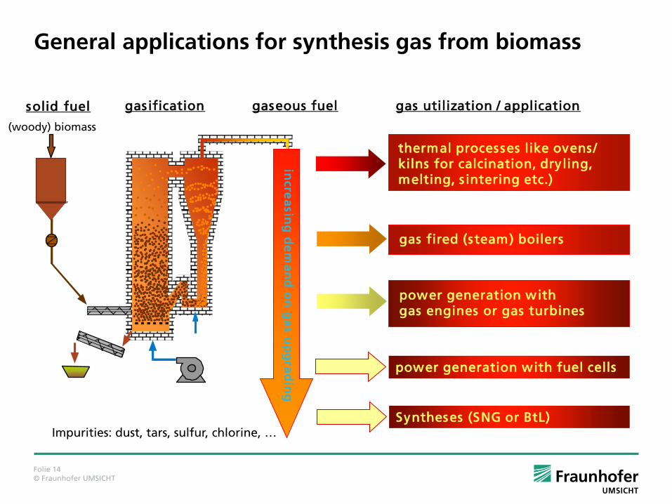
General applications for synthesis gas from biomass
(woody) biomass
gaseous fuel
thermal processes like ovens / kilns for calcination, dryling, melting, s intering etc.)
gas fired (steam) boilers
power generation with gas engines or gas turbines
incre
asin
g d
em
an
d o
n g
as u
pg
rad
ing
gasification solid fuel gas utilization / application
power generation with fuel cells
Syntheses (SNG or BtL) Impurities: dust, tars, sulfur, chlorine, …

Folie 15 © Fraunhofer UMSICHT
Challanges for Gasification
3 main difficulties
Solid Fuel Dosing
affects mainly fulidized beds
requirements: continuous dosing (potentially against pressure)
fuel flowability very different: pellets, wood chips, chaff
Distribution of gasifying agent over cross section
affects mainly fixed beds
requirement: even distribution over complete cross section
reactive requirement on biomass fuel: no fines allowed
main reason for scale-up limit (cocurrent) at about 1 MW fuel input
Gas Cleaning
Tar, Sulfur, Chlorine, Ammonia, …

© Fraunhofer
Outline
1. Fraunhofer-Gesellschaft and Fraunhofer UMSICHT
2. Fundamentals of solid fuel gasification
3. Gasification plants at Fraunhofer UMSICHT
4. Bandwidth of fuels used
5. Challenges for future plants
6. Summary

Folie 17 © Fraunhofer UMSICHT
Schematic drawing of fluidized bed gasification plant

Folie 18 © Fraunhofer UMSICHT
Photograph of fluidized bed gasification plant (500 kW)

Folie 19 © Fraunhofer UMSICHT
Schematic drawing of fluidized bed gasification plant

Folie 20 © Fraunhofer UMSICHT
Photograph of fluidized bed gasification plant (100 kW)
© Fraunhofer
Outline
1. Fraunhofer-Gesellschaft and Fraunhofer UMSICHT
2. Fundamentals of solid fuel gasification
3. Gasification plants at Fraunhofer UMSICHT
4. Bandwidth of fuels used
5. Challenges for future plants
6. Summary

Folie 22 © Fraunhofer UMSICHT
Fuels used Circulating fluidized bed
Wood flakes from reciprocating saw (FL)
Shredded demolition wood (DW)
Shredded plywood (PW) (ammonium sulfate)
Sewage sludge (SS) (dried, granulated)
Vulcanized rubber (VR) (Peeled from used tires before retreading)
Bubbling fluidized bed
Shredded demolition wood (DW)
Wood chips (WC)
Shredded willow from short rotation forestry (WS)
Shredded peat briquettes (PB)
Wood pellets (WP)
RRBF (MS) (refined renewable biomass fuel / conditioned MSW from MBT)

Folie 23 © Fraunhofer UMSICHT
Fuels used Fuel bulk density LHV water content ash content particle size
kg/m3 MJ/kg weight-% weight-% mm
FL 151 16.6 9 0.7 3 - 5
DW 15.4 10.9 3.0 (0)1 - 5
PW 14.8 18.2 1.15 < 30
SS 713 8.75 5.3 47.0 (0)2 - 5
VR 524 41.8* 0.1 < 1 5 - 8
WC 255 16.5 8 0.6 1 - 30
WS 15.5 11.0 1.16 0 - 40
PB 17.9 10.2 2.49 0 - 30
WP 726 18.0 4 0.5 6x20
MS 302 11.0 13-25 22-32 0 – 30
FL: Wood flakes; DW: Demolition wood; PW; Plywood; SS: Sewage Sludge; VR: Vulcanized rubber; WC: Wood chips; WS: Willow from short rotation forestry; PB: Peat briquettes; WP: Wood pellets; MS: Mixed municipal solid waste (from MBT + conditioning)
*34.4 MJ/kg w/o carbon black

Folie 24 © Fraunhofer UMSICHT
Dosing systems Circulating fluidized bed
Storage hopper 10 m3, 1,4 x 1,4 x 5 m, discharge with screw conveyor
Screw conveyor for fuel elevation
Dosing hopper on scales (discharge via vibrating chute): mass dosing
Rotary valve as pressure lock
Screw feeder (jacket and shaft cooled)
Bubbling fluidized bed
Storage hopper 36 m3, container with pushfloor, discharge with screw conveyor
Screw conveyor for fuel elevation
Dosing hopper with frequency controlled screw conveyor discharge: volume dosing calibration needed for every fuel
Rotary valve as pressure lock
Screw feeder (jacket and shaft cooled)

© Fraunhofer
Outline
1. Fraunhofer-Gesellschaft and Fraunhofer UMSICHT
2. Fundamentals of solid fuel gasification
3. Gasification plants at Fraunhofer UMSICHT
4. Bandwidth of fuels used
5. Challenges for future plants
6. Summary
Folie 26 © Fraunhofer UMSICHT
Challenges Solid fuel handling
Flowability of fuel -> bridging in storage hoppers / uneven transport on vibrating chute
Folie 27 © Fraunhofer UMSICHT
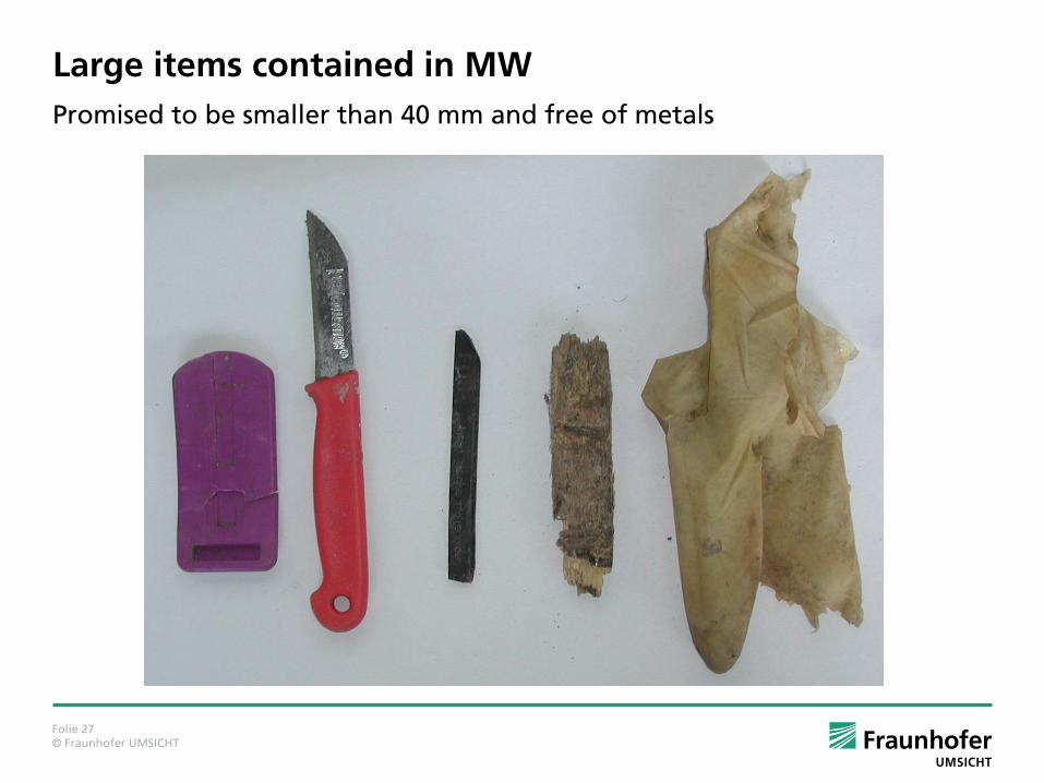
Large items contained in MW
Promised to be smaller than 40 mm and free of metals

Folie 28 © Fraunhofer UMSICHT
Calibration of dosing screws – 1. batch as delivered
0
5
10
15
20
25
30
35
40
0 0,2 0,4 0,6 0,8 1 1,2
[kg]
[h]
100%A
100%B
80%
60%
40%

Folie 29 © Fraunhofer UMSICHT
Calibration of dosing screws – 2. batch
0
5
10
15
20
25
30
35
40
45
50
0,00 0,20 0,40 0,60 0,80 1,00 1,20
[kg]
[h]
SWS- kalibrierung Dosierschnecke - EBS 27.05.2015
100%
90%
80%
70%
60%
50%
40%
30%
20%

Folie 30 © Fraunhofer UMSICHT
Calibration of dosing screws – 2. batch
y = 0,938x
10
15
20
25
30
35
40
45
50
55
60
65
70
75
80
85
90
95
100
10 15 20 25 30 35 40 45 50 55 60 65 70 75 80 85 90 95 100
[kg/
h]
[%]
SWS- kalibrierung Dosierschnecke - EBS 27.05.2015

Folie 31 © Fraunhofer UMSICHT
Challenges Solid fuel handling
Flowability of fuel -> bridging in storage hoppers / uneven transport on vibrating chute
Melting/Softening in feeding screw
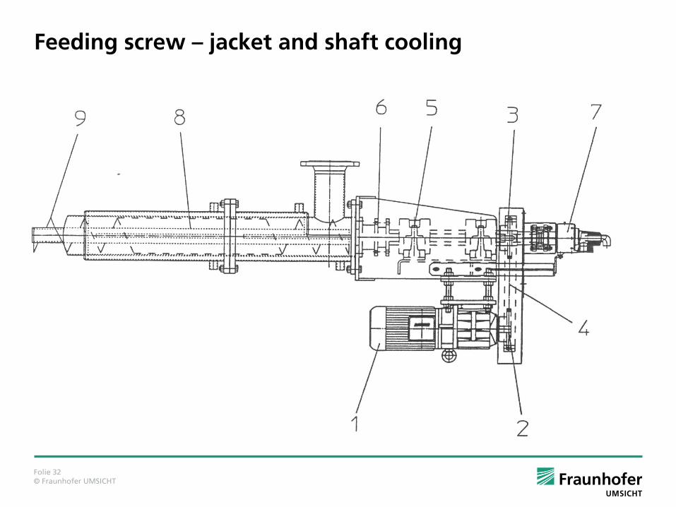
Folie 32 © Fraunhofer UMSICHT
Feeding screw – jacket and shaft cooling

Folie 33 © Fraunhofer UMSICHT
Challenges Solid fuel handling
Flowability of fuel -> bridging in storage hoppers / uneven transport on vibrating chute
Melting/Softening in feeding screw
High amounts of fines (< 1 mm): discharge with sealing air
Producer gas cleaning
High sulfur content with SS, PW and esp. VR SS and PW needed frequent catalyst regeneration gas from VR only usable for combustion (with flue gas desulfurization)
High ammonia content with SS, PW -> installation of ammonia scrubber
Soot accumulation in circulating fluidized bed with VR (extremely different reactivity of rubber and carbon black)
Variety of contaminants for MSW-based fuel -> combustion preferable

© Fraunhofer
Outline
1. Fraunhofer-Gesellschaft and Fraunhofer UMSICHT
2. Fundamentals of solid fuel gasification
3. Gasification plants at Fraunhofer UMSICHT
4. Bandwidth of fuels used
5. Challenges for future plants
6. Summary
Folie 35 © Fraunhofer UMSICHT
Summary
Proven fuel bandwidth for gasifier
Water content from 0 up to 40 %
Ash content from 0 up to 50 % (ash softening temperature > 950 °C)
Minimum LHV: 6 MJ/kg (1.7 kWh/kg) as received
Woody biomass, sewage sludge (dried, granulated), rubber, RRBF, etc.
Challenges
Gas cleaning to be specially designed for each fuel
Gas cleaning for high contaminated fuels (gas boiler + steam cycle)
Minimum flowability required (reproducible)
Fuels composed of components with very different reactivity may need special attention / reactor design (e.g. rubber: isoprene and carbon black)

Folie 36 © Fraunhofer UMSICHT
Fraunhofer UMSICHT Department Biorefinery & Biofuels
Фотография: photocase.de
Thank You for Your kind attention!
Contact: Fraunhofer UMSICHT Osterfelder Strasse 3, 46047 Oberhausen, Germany E-Mail: [email protected] Internet: http://www.umsicht.fraunhofer.de/en
Dipl.-Ing. Tim Schulzke Telephone: +49 208 8598 1155 E-Mail: [email protected]


