
Installation Guide
Fuller Advantage™ Automated TransmissionTRIG0980 EN-USJune 2016
FA(M)-XX810B-EA3FAO-XX810C-EA3FAO(M)-XX810C-EA3FAO(M)-XX810S-EC3

Warnings and CautionsW
arnings and Cautions
Introduction and General Information
Warnings and Cautions
Important Notice
Any reference to brand name in this publication is made as an example of the types of tools and materials recommended for use and should not be considered an endorsement. Equivalents may be used.
The description and specifications contained in this service publication are current at the time of printing.
Eaton reserves the right to discontinue or modify its models and/or procedures and to change specifications at any time without notice.
This symbol is used throughout this manual to call attention to procedures where carelessness or failure to follow specific instructions may result in personal injury and/or component damage.
Departure from the instructions, choice of tools, mater ials and recommended parts mentioned in this publication may jeopardize the personal safety of the service technician or vehicle operator.
Warning: Failure to follow indicated procedures creates a high r isk of personal injury to the servicing technician.
Caution: Failure to follow indicated procedures may cause component damage or malfunction.
Important: Highly recommended procedures for proper service of this unit.
Note: Additional service information not covered in the service procedures.
Tip: Helpful removal and installation procedures to aid in the service of this uni t.
!

Table of Contents
Section 1: Introduction / General InformationIntroduction and General Information .......................................................................................................... iAbout this Manual ........................................................................................................................................ 1Product Familiarization................................................................................................................................. 3Suggested Tools/Publications...................................................................................................................... 5Vendor List................................................................................................................................................... 6
Section 2: Vehicle Space ClaimVehicle Space Claim..................................................................................................................................... 7Shift Label Requirements ............................................................................................................................. 8Eaton Shift Console Space Requirements .................................................................................................... 9Eaton Shift Lever and Tower Space Requirements....................................................................................... 10Vehicle Space Claim..................................................................................................................................... 11
Section 3: Clutch InterfaceClutch Interface ............................................................................................................................................ 13ECA Clutch Installation ................................................................................................................................. 14
Section 4: Transmission InterfaceTransmission Interface................................................................................................................................. 16Air Supply and Air Drying Requirements...................................................................................................... 19Lubrication Requirements and Specifications .............................................................................................. 20Cooler Requirements ................................................................................................................................... 23
Section 5: Electrical System InterfaceElectrical Wiring Requirements .................................................................................................................... 25Electrical Wiring Recommendations ............................................................................................................ 30Power Harness............................................................................................................................................. 33Ignition Circuit Detail.................................................................................................................................... 37Typical Start Enable Relay Circuit................................................................................................................. 38Typical System with Eaton Push Button....................................................................................................... 49Typical System with Eaton Shift Lever ......................................................................................................... 42Dimmer Control Input Connection ............................................................................................................... 43Diagnostic Connector................................................................................................................................... 44J1939/15 Data Link ...................................................................................................................................... 45SAE J1939 Data Link Broadcast Messages .................................................................................................. 47SAE J1939 Data Link Received Messages.................................................................................................... 52SAE J1587 Data Link Broadcast Messages .................................................................................................. 58

Table of ContentsTable of Contents
Section 6: System Integration SpecificationsGear Display................................................................................................................................................. 59Hill Start Aid ................................................................................................................................................ 61Auto Neutral ................................................................................................................................................ 62Urge to Move .............................................................................................................................................. 62Automatic Traction Control (ATC) ............................................................................................................... 63Shift Input Device ........................................................................................................................................ 63Engine ......................................................................................................................................................... 63Remote Throttle Enable ............................................................................................................................... 63Alert Tone .................................................................................................................................................... 64Service Lamp .............................................................................................................................................. 64OEM Vehicle Equipment Programming Station (VEPS) ............................................................................... 64
Section 7: Auxiliary Equipment InterfacePTO Inputs and Configurations .................................................................................................................... 65PTO Wiring Diagrams .................................................................................................................................. 67
Section 8: Line Inspection and End of LineLine Inspection and Road Test Instructions ................................................................................................. 69Line Inspection Form - Fuller Advantage Automated Models ....................................................................... 74Line Inspection Form OEM Wiring Connector/Harness ................................................................................ 75Diagnostic Procedure................................................................................................................................... 76
Section 9: AppendixPower/Remote Throttle ................................................................................................................................ 78Wiring Diagram - OEM Responsibility.......................................................................................................... 85Fuller Advantage™ Automated Transmission with Analog Shifter Wiring Diagram ...................................... 87Fuller Advantage™ Automated Transmission with Push Button Shifter Wiring Diagram.............................. 89Connector Pin Descriptions.......................................................................................................................... 91Torque Specifications................................................................................................................................... 93Change Control Log ..................................................................................................................................... 94

1
General Information
About this Manual
This installation guide references design employing the Generation 2 ECA Power Pack being supplied after November 1, 2015. ECA motors used prior to that date will not have electrical connection information available in this guide.
This Eaton® publication is intended to be a reference guide for the installation of the Fuller Advantage Automated Transmissions. General vehicle and transmission information is provided to cover the wide range of applications. This information benefits the OEM installer by providing the correct installation procedures to ensure the utmost in satisfactory operation and long service life. For additional transmission information, see the Suggested Tools section in this manual. For specific engine information contact the engine OEM.
Failure to adhere to Eaton Installation Requirements may affect transmission performance and/or warranty coverage.
Fuller Advantage Automated Transmissions are compatible with electronically governed engines equipped with a J1939 data link and certified by Eaton. Transmissions installed at OEM facilities shall meet and be approved by Eaton Application Engineering. Contact Eaton Application Engineering or your OEM Application Engineering department for the proper Application form. All applications shall be submitted for approval.
OEM Design Responsibility
OEM facilities shall submit a design package to Eaton OEM Engineering Support Group for approval prior to any OEM build. A design package consists of the following information.
Transmission air supply: Source of air supply and routing and clipping of air supply line.
Transmission cooling system: Cooler type and capacity, cooler hose(s) routing and clipping.
Battery power and ground: Detailed drawing of battery power and ground scheme.
Individual harness drawings: Construction detail of individual wiring harnesses including harness routing location and clipping points.
Wiring schematic: High-level schematic of how this transmission interfaces with the vehicle.
Application Approval
Fuller Advantage Automated Transmission Systems installed at OEM facilities must meet the requirements and be approved using the Eaton Transmission Application Approval Form. Please contact Eaton Application Engineering or your OEM's Applica-tion department for the latest Application form.
• Driveline Torque Requirements - Driveline angular acceleration and driveline torque shall not exceed requirements stated in Eaton Application Guideline specification TRAG2600.
• Applications and PTO Applications- refer to Application Guidelines Manual TRAG2600 and PTO Torque Limits TMIB0127 for PTO application guidelines.
Every effort has been made to ensure the accuracy of the information contained in this manual. However, Eaton makes no war-ranty, either expressed or implied, based on the information provided. With each new application, engine manufactures should be contacted to make sure desired engines are compatible with these systems.
2
General InformationGeneral
Information
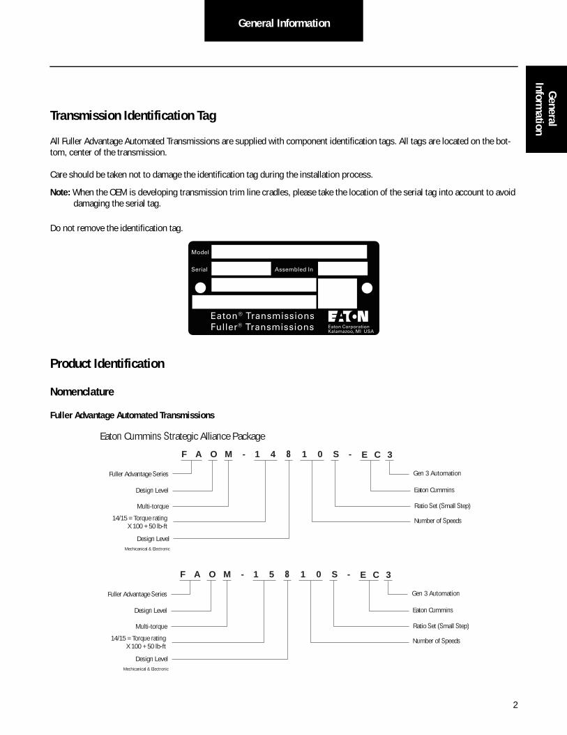
Transmission Identification Tag
All Fuller Advantage Automated Transmissions are supplied with component identification tags. All tags are located on the bot-tom, center of the transmission.
Care should be taken not to damage the identification tag during the installation process.
Note: When the OEM is developing transmission trim line cradles, please take the location of the serial tag into account to avoid damaging the serial tag.
Do not remove the identification tag.
Product Identification
Nomenclature
Fuller Advantage Automated Transmissions
Eaton® TransmissionsFuller® Transmissions
Model
Serial Assembled In
Eaton CorporationKalamazoo, MI USA
F
Fuller Advantage Series
M -
14/15 = Torque ratingX 100 + 50 lb-ft
Multi-torque
Eaton Cummins
Ratio Set (Small Step)
Number of Speeds
1 4 8 1 0 S - E C 3
Gen 3 Automation
Design Level
Mechicanical & Electronic
Eaton Cummins Strategic Alliance Package
A O
Design Level
F
Fuller Advantage Series
M -
14/15 = Torque ratingX 100 + 50 lb-ft
Multi-torque
Eaton Cummins
Ratio Set (Small Step)
Number of Speeds
1 5 8 1 0 S - E C 3
Gen 3 Automation
Design Level
Mechicanical & Electronic
A O
Design Level
3
General Information
Product Familiarization
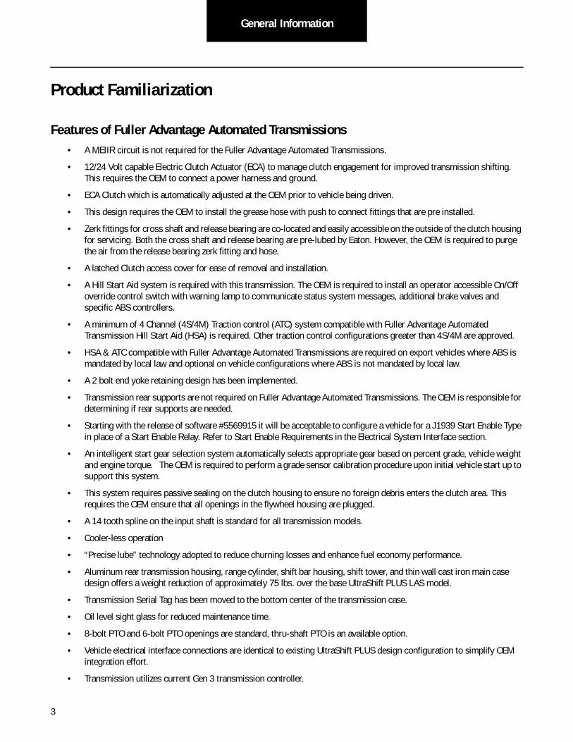
Features of Fuller Advantage Automated Transmissions• A MEIIR circuit is not required for the Fuller Advantage Automated Transmissions.
• 12/24 Volt capable Electric Clutch Actuator (ECA) to manage clutch engagement for improved transmission shifting. This requires the OEM to connect a power harness and ground.
• ECA Clutch which is automatically adjusted at the OEM prior to vehicle being driven.
• This design requires the OEM to install the grease hose with push to connect fittings that are pre installed.
• Zerk fittings for cross shaft and release bearing are co-located and easily accessible on the outside of the clutch housing for servicing. Both the cross shaft and release bearing are pre-lubed by Eaton. However, the OEM is required to purge the air from the release bearing zerk fitting and hose.
• A latched Clutch access cover for ease of removal and installation.
• A Hill Start Aid system is required with this transmission. The OEM is required to install an operator accessible On/Off override control switch with warning lamp to communicate status system messages, additional brake valves and specific ABS controllers.
• A minimum of 4 Channel (4S/4M) Traction control (ATC) system compatible with Fuller Advantage Automated Transmission Hill Start Aid (HSA) is required. Other traction control configurations greater than 4S/4M are approved.
• HSA & ATC compatible with Fuller Advantage Automated Transmissions are required on export vehicles where ABS is mandated by local law and optional on vehicle configurations where ABS is not mandated by local law.
• A 2 bolt end yoke retaining design has been implemented.
• Transmission rear supports are not required on Fuller Advantage Automated Transmissions. The OEM is responsible for determining if rear supports are needed.
• Starting with the release of software #5569915 it will be acceptable to configure a vehicle for a J1939 Start Enable Type in place of a Start Enable Relay. Refer to Start Enable Requirements in the Electrical System Interface section.
• An intelligent start gear selection system automatically selects appropriate gear based on percent grade, vehicle weight and engine torque. The OEM is required to perform a grade sensor calibration procedure upon initial vehicle start up to support this system.
• This system requires passive sealing on the clutch housing to ensure no foreign debris enters the clutch area. This requires the OEM ensure that all openings in the flywheel housing are plugged.
• A 14 tooth spline on the input shaft is standard for all transmission models.
• Cooler-less operation
• “Precise lube” technology adopted to reduce churning losses and enhance fuel economy performance.
• Aluminum rear transmission housing, range cylinder, shift bar housing, shift tower, and thin wall cast iron main case design offers a weight reduction of approximately 75 lbs. over the base UltraShift PLUS LAS model.
• Transmission Serial Tag has been moved to the bottom center of the transmission case.
• Oil level sight glass for reduced maintenance time.
• 8-bolt PTO and 6-bolt PTO openings are standard, thru-shaft PTO is an available option.
• Vehicle electrical interface connections are identical to existing UltraShift PLUS design configuration to simplify OEM integration effort.
• Transmission utilizes current Gen 3 transmission controller.

4
General InformationGeneral
Information
• An auto neutral feature is required with this transmission which forces neutral in all instances when the parking brake is applied. This requires the OEM to install and connect a pressure switch in the parking brake valve circuit.
- Starting with the release of software #5569892, a data link signal will be an acceptable substitute for the pressure switch requirement.
• Mechanical transmission interface dimensions are identical to that of the FAS manual transmission model which simpli-fies the OEM’s integration effort.
• Reduced oil capacity requirement, reduces weight/cost.
• Product-specific J1939 messaging.

5
General Information
Suggested Tools/Publications
For more information contact your OEM quality representative.
O.E. Tool & Equipment Group/Kent-Moore SPX Corporation 1(800) 520-2584
Kent-Moore Part no. Description
5505027 Volt/Ohm Meter (Standard commercially available VOM)
O.E. Tool & Equipment Group/Kent-Moore SPX Corporation 1(800) 328-6657
Kent-Moore Part no. Description
J-43318 Eaton Test Adapter Kit
Liberty Circuits Corporation (269) 226-8743
Part No. Description
500-432 Pull-To-Neutral Box
500-442 Grade Sensor Calibration Box
Eaton Service Parts 1 (800) 826-HELP (1-800-826-4357)
Part No. Description
T-100432 Clutch Alignment Tool, 14T, 2”
Deutsch 951-765-2250
Part No. Description
DTT-20-02 Hand Crimping Tool - Low Power Pins (size 20)
DTT-12-00 Hand Crimping Tool - High Power Pins (size 12)
Service Publications
TRSM0980 Service Manual for External components
TRTS0980 Troubleshooting Guide
TRDR0980 Drivers Instructions
Dearborn Group Technology
Part No. Description
DG-DPA IV PLUS Protocol Adaptor
Nexiq Technologies
Part No. Description
104004 Pro-link GRAPHIC Scan Tool
6006001 HD Scan Tool Kit

6
General InformationGeneral
Information
Vendor List
Eaton Vehicle Controls Business UnitJ1939 Auto Shift Display
Contact Phone Number: 919 202 5220
www.commercialcontrols.eaton.com
BELDEN WIRE AND CABLE(HIL and J1939 Cable)
P.O. Box 1980
Richmond, IN 47375
(317) 983-5200
Fax (765) 983-5294
www.Belden.com
BRAND-REX CO.(J1939 Cable)
300 Brickston Square
Andover, MA 01801
(978) 933-5100
www.brand-rex.com
CHAMPLAIN CABLE CO.(J1939 Cable)
12 Hercules Dr.
Colchester, VT 05446
(802) 655-2121
Fax (802) 654-4224
www.champcable.com
DEUTSCH(Connectors)
Industrial Products Division
37140 Industrial Ave.
Hemet, CA 92545
(909) 765-2250
Fax (909) 765-2255
www.deutschipd.com
www.laddinc.com (Ladd Industries)
PACKARD Electric(Connectors)
Pioneer-Standard Electronics, Inc.
Packard Branch
5440 Naiman Parkway
Solon, OH 44139
1-800-PARKARD (722-5273)
Fax (219) 378-6650
www.delphiconnect.com
RAYCHEM(Wire)
Electronics OEM Components Division
300 Construction Drive
Menlo Park, CA 94025-1164
1-800-260-9909
Fax United States (800) 260-9999
Fax Worldwide (650) 361-5579
www.raychem.com
LIBERTY CIRCUITS CORPORATION630 East Walnut
Kalamazoo, MI 49007
(269) 226-8743

7
Vehicle Space Claim
Vehicle Space Claim
Cab Floor Access Plate Requirements Note: Refer to the “Transmission Component Temperature Requirements” on page 23.
Cab Floor Access Plate Requirements1. A cab floor access plate is required for access and removal of components from the transmission top. Plate size (mini-
mum: 15”x12”) shall be sufficient to allow removal of the Transmission Electronic Control Unit or the Electric Shifter.
Easily accessible and removable transmission access plate.minimum size is 15” x 12”
DASH
Driver'sSeat
PassSeat
15”
12”
8
Vehicle Space ClaimVehicle Space
Claim
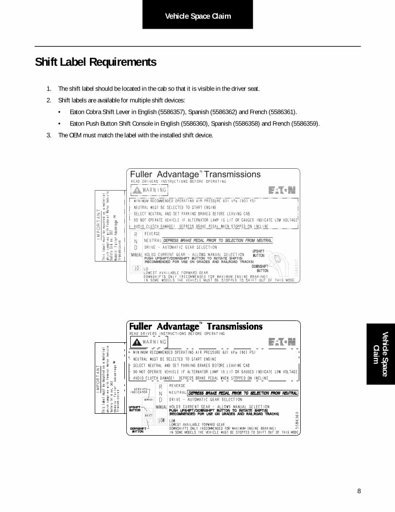
Shift Label Requirements
1. The shift label should be located in the cab so that it is visible in the driver seat.
2. Shift labels are available for multiple shift devices:
• Eaton Cobra Shift Lever in English (5586357), Spanish (5586362) and French (5586361).
• Eaton Push Button Shift Console in English (5586360), Spanish (5586358) and French (5586359).
3. The OEM must match the label with the installed shift device.
Fuller Advantage Transmissions

9
Vehicle Space Claim
Eaton Shift Console Space Requirements
Mates with 30-way packard connector with body #15492553 and terminals #12103881
12.2[.48]
38.74 - 40.76[1.525 - 1.605]
75.2[2.96]
29.6[1.16]
37.54[1.478]
83.8[3.30]
172.7[6.80]
164.1[6.46]
101.98[4.015]
60.6[2.39]
9.59[.378]
166.62[6.56]
PANEL CUT OUT DIMENSIONS
4X R.10 MAX
77.72[3.06]
2X #8-32 UNC
10
Vehicle Space ClaimVehicle Space
Claim
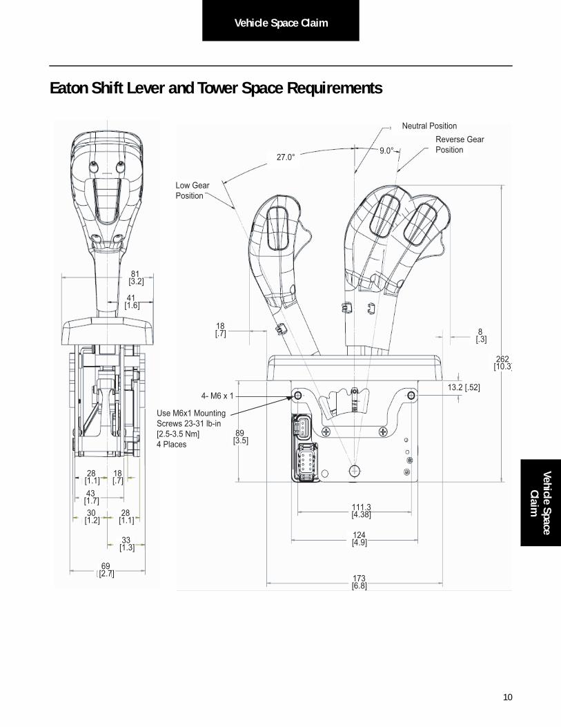
Eaton Shift Lever and Tower Space Requirements
81[3.2]
41[1.6]
28[1.1]
18[.7]
43[1.7]30
[1.2]28
[1.1]
33[1.3]
69[2.7]
81[3.2]
41[1.6]
28[1.1]
18[.7]
43[1.7]30
[1.2]28
[1.1]
33[1.3]
69[2.7]
18[.7] 8
[.3]
262[10.3]
13.2 [.52]
89[3.5]
111.3[4.38]
124[4.9]
173[6.8]
18[.7] 8
[.3]
262[10.3]
13.2 [.52]
89[3.5]
111.3[4.38]
124[4.9]
173[6.8]
Low GearPosition
Neutral PositionReverse Gear Position
27.0°9.0°
4- M6 x 1
Use M6x1 Mounting Screws 23-31 lb-in[2.5-3.5 Nm] 4 Places

11
Vehicle Space Claim
Vehicle Space Claim
Fuller Advantage Automated Transmission
Warning: Eaton does not allow removing fasteners from any gasketed surface as the potential for leaks is created by doing so.!

12
Vehicle Space ClaimVehicle Space
Claim

13
Clutch Interface
Clutch Interface
Pilot Bearing Specifications
The OEM is responsible for the design and selection of pilot bearings to mate with our product. Eaton recommends high quality pilot bearings procured from Original Equipment Manufacturers. Significant decrease in life may occur with the use of generic brand pilot bearings.
The following pilot bearings are currently the minimum Eaton Clutch Division recommends. The operating temperature that the pilot bearing sees has increased in the last several years. This creates operating conditions that are no longer acceptable to the standard pilot bearings and grease. In addition, the life of the clutch has increased. The use of high temperature grease and Viton seals are now mandatory to ensure adequate bearing life. Pilot bearing failure usually results in a warranty claim for drag or clutch noise. This results in a claim against Eaton Clutch.
Below is a list of the recommended Pilot Bearings. All of these bearings have Viton seals and a high temperature grease in addi-tion to a C3 fit. It is acceptable to use synthetic high temperature grease and a C5 fit if desired.
If the supplier specific bearing is no longer available, contact the supplier for an equivalent alternative bearing.
Grease Hose
P/N 4306950 Sold as loose part.
Insert the grease hose into the pre-installed push to connect fitting in the clutch release bearing. As the transmission is being brought up to the engine stick the hose through the grommet in the clutch housing next to the cross shaft grease hose. As the transmission is moved closer to the engine continue to lightly pull the hose, this will keep the release bearing in proper alignment with the fork and the hose from getting caught inside the clutch housing. Once the transmission is bolted to the engine with an approved cutter, using care to make a clean cut that will not damage the O-ring in the push to connect fitting, push the hose into the pre installed push to connect fitting on the outside of the clutch housing.
Note: Air must be purged from the grease hose. This will take approximately 5 ml or 5 to 6 pumps of a typical grease gun.
Vendor Seal Type Bearing Series 6205 Bearing Series 6306 Bearing Series 6006
NTN Viton 6205 LLUA1/C3 6306 LLUA1/C3 6006 LLUA1 C3/LX16
KOYO Viton 6205 2RKF-S2/C3 6306 2RKF-S2/C3 -
NSK Viton 6205 DDU7/C4 ENS 6306 DDU7/C4 ENS 6006 DDWA18A C4/ENSS
SKF Viton 6205 2RS2/C3 6306 2RS2/C3 -
FED-MOG Viton 6205 VV/C3 6306 VV/C3 -
PEER Viton 6205-2VRLD-C3 6306-2VRLD-C3 6006-2VRLD-C3

14
Clutch InterfaceClutch Interface
ECA Clutch Installation
Clutch Requirements - All Fuller Advantage Automated Transmissions require an adjustment free ECA clutch:
• Up to 1850 lb-ft rating (P/N 122002-35)
Installation Instructions
• Install two guide studs into the upper mounting holes. Be sure to use guide studs to ensure proper alignment of the clutch assembly to the flywheel.
• Use a lifting device to pick up clutch.
Note: The intermediate plate is bolted to the cover assembly and the rear disc is in between the pressure plate and the intermedi-ate plate. Do not unbolt the intermediate plate from the cover assembly.
• Insert aligning tool through bearing and splined strapped driven disc.
Note: The alignment tool for the Fuller Advantage Automated Transmission ECA clutch is a 14-tooth shaft and is 1-3/4" longer. A modified input shaft (P/N 4306034) can be used as an alignment tool or tool number T-100432 shown in Appendix can be used to manufacture a tool. This is the same alignment shaft that is used for UltraShift PLUS clutches.
• Install second disc onto aligning tool. Follow the orientation instructions on the disc.
• Slide the clutch assembly over the guide studs and start six of the clutch mounting bolts. Start at the lower left when tightening the clutch mounting bolts. This will ensure that the clutch is properly pulled into the flywheel pilot. Failure to do this could result improper piloting of the clutch and cause clutch damage. Tighten the clutch mounting bolts in a crossing pattern to 40-50 ft lbs (54-68 Nm) as on any other clutch. Remove the guide studs and install the two remain-ing bolts.
• Remove shipping bolts in an even 1/4 turn crossing pattern.
• Remove the alignment shaft.
• The release bearing shall be positioned so that the orientation of the lube fitting/hose is in the 4 o'clock position.
Note: No initial clutch adjustment required.
ECA Removal and Assembly Instructions
If transmission removal is necessary the ECA must first be released from the clutch by one of two methods.
The first method is to use ServiceRanger:
1. Go into Advanced Product Functions and select ECA clutch service utility. This page will give instructions for a variety of operations.
2. Select “Move to Service Position” and click next.
3. Once in the Electronic Clutch Actuator service utility, select the button that says “Move to Service Position”. This will rotate the clutch fork to the open position so the transmission can be pulled back from the engine with out damaging the clutch.

15
Clutch Interface
The other option is to remove the ECA by using the following instructions. Refer to the following procedure in the event the Elec-tric Clutch Actuator assembly requires removal and replacement:
ECA Removal:
• Cut tie straps which secures the ECA harness (if applicable)
• Disconnect the harness to the ECA
• Remove the (4) 3/8"-16 capscrews that secure the ECA bracket. Remove the bracket.
• Remove the (4) 3/8"-16 capscrews that secure the ECA to the housing. Remove the ECA. The ECA will need to be rotated to line up a locating pin with a notch in the housing in order to remove the ECA from the clutch housing.
ECA Installation
• Ensure the clutch fork is positioned against the stop.
• Apply anti-seize compound to the bore of the ECA.
• The ECA will need to be rotated to line up a locating pin with a notch in the housing in order to install the ECA into the clutch housing.
• Install the ECA onto the housing, while matching the splines of the ECA motor to the shaft.
• Install (4) 3/8"-16 capscrews to secure the ECA to the housing. Torque to 35-45 ft lbs.
• Install (4) 3/8"-16 capscrews to secure the ECA support bracket with applying loctite 242 to the threads. Torque cap-screws to 35-45 ft lbs.
• Reconnect the appropriate wire connectors.
• Replace tie straps that secure harnessing.

16
Transmission InterfaceTransm
ission Interface
Transmission Interface
HandlingHandle the transmission carefully to avoid damage to the transmission components and surrounding vehicle components.
• Use a hoist or transmission jack that permits precise control of the transmission movement during installation.
Transmission Preparations
Note: Eaton has provided several brackets that can be used for clipping vehicle components to. ECU, sensor, and lifting eye fasteners are not to be used for securing additional OEM brackets under any circumstances. This includes cap screws used to fasten the shift bar housing, rear housing, bearing covers, and PTO covers. Removal of these can compromise transmission system operation and overall system reliability.
Note: No mechanical speedometer. The rear bearing cover will offer two (2) push-in sensor openings at 6 and 12 o’clock positions. The tone wheel has 16 teeth, as standard.
Reverse and Neutral Switches
Reverse and Neutral Switch OptionsReverse and neutral switch openings are standard on all heavy duty Fuller transmissions. The transmission will be shipped with plugs in these openings, unless switches are ordered by the OEM and pre-installed by Eaton.
Supply Voltage: 12V System (9V–16V)24V System (16V–32V)
Switching Currents: 10 amps for 12V circuit3 amps for 24V Circuit
Sensor Loads: < 1 amp for 12V or 24V
Switch State: Normally Closed
Reverse SwitchLocation: Opening is located at the rear of the shift bar housing. See top view drawings for location.
Switch type: Normally open ball type switch.
Thread size: 0.5625-18 UNF-2B.
Mating Connector: Options are screw terminals or Weather Pack.
Neutral Switch
Note: The transmission neutral switch provides an indication of neutral, but does not guarantee a true neutral position or provide a “confirmed neutral” output. This switch shall not be used as the sole indication that the transmission is in neutral.
Location: Opening is located on the left side of the shift bar housing. See top view drawings for location.
Switch type: Normally open ball type switch.
Thread size: 0.750-16 UNF-3B.
Mating connector: Options are screw terminals or Weather Pack.

17
Transmission Interface
End Yoke Retaining DesignAll Fuller Advantage Automated Transmissions have a two bolt retainer plate design to fasten and retain the end yoke. These transmission will be shipped with end yokes installed. A dual spindle driver is recommended to install the yokes. If a dual spindle is not available, special care shall be exercised to snug each bolt to 35 ft-lbs prior to attaining full torque of 84–92 ft-lbs. For reference, these bolts are M12 x 1.25 x 60 mm Grade 10.9 per DIN 6921.
Mounting Transmission to EngineUse the two transmission lifting eyes provided. The lifting eye position shall not be changed on the transmission. Do not remove the Electric Shifter at any time.
• Use a two point lift chain or transmission jack with a minimum capacity of 1500 lbs.
• Inspect the engine to transmission mating surfaces for damage or debris prior to installation. Make sure the engine flywheel housing face, transmission clutch housing face, input shaft, etc. are free of paint, debris, rust, and any type of damage before installation.
• The transmission is shipped in gear until the vehicle is powered up with the key switch. Use a Pull-to-Neutral-Box to disengage the transmission or rotate the axles to align the transmission prop shaft.
• Input Shaft To Clutch Alignment - the transmission is shipped from Eaton with the transmission in gear. The transmission shall be in gear in order to rotate the input shaft by turning the output shaft/yoke. The transmission will automatically reset to the neutral position as soon as the vehicle is powered up (key switched on). In the event that the transmission is not received in gear, the input shaft will have to be manually indexed to mate up with the clutch splines.
• Transmission is shipped from Eaton with the ECA in the fully retracted position, allowing clearance for the release bearing. Ensure the grease fitting on the release bearing is at approximately the 4 o'clock position to allow installation of the of grease tube.
• Adjust the lift chain or transmission jack to obtain the same relative angle as the engine. The face of the engine flywheel housing and the face of the transmission clutch housing shall be parallel during installation. Rotate the output shaft/yoke while sliding the input shaft into the clutch to line up the splines. If the transmission is properly aligned and the clutch splines are properly aligned, very little force is required to slide the input shaft through the clutch and into the pilot bearing.
• If interference is encountered, move the transmission away from the engine to investigate the cause. The use of excessive force to overcome misalignment may cause damage to the transmission input shaft and the clutch.
• The clutch/yoke will remain in the released position during the entire transmission installation. At key on the ECA will rotate the clutch/yoke to its proper position.
• Once the transmission is seated against the engine flywheel housing, align the clutch housing bolt holes with the engine flywheel housing bolt holes and install all capscrews and tighten finger tight.
Note: The clutch housing shall be flush against the engine flywheel housing before tightening any capscrews. Do not use the capscrews to seat housing.
• The ECA and ECA cover will be shipped with the transmission to the OEM. This requires a change to the fastening procedure. Initially tighten (4) capscrews 90 degrees apart starting with the capscrew immediately above the ECA. Then tighten the remaining (8) capscrews.
Note: The use of a swivel socket may be required for the (2) bolts entering through the ECA device.
Note: Do not tighten any mounting capscrews until all capscrews have been installed and finger tightened. Do not remove the transmission support chain or jack until all mounting bolts have been tightened.
18
Transmission InterfaceTransm
ission Interface
OEM Plant Serviceability
Warning: If transmission removal is necessary the ECA must first be released from the clutch by one of two methods. The first method would be to use ServiceRanger. Go into Advanced Product Functions, select ECA clutch service utility. This page will give instructions for a variety of operations, you will want “Move to Service Position” click next. once you are in the Electronic Clutch Actuator service utility select the button that says Move to Service Position. This will rotate the clutch fork to the open position where the transmission can be pulled back from the engine with out damaging the clutch.
The other option is to remove the ECA by following the instructions in the ECA section.
Using Rear SupportsThe OEM is responsible for determining if rear supports are needed. The OEM is responsible for nodal mount and rear mountdesign. Refer to OEM for rear or nodal mount fastener torque specifications.
!

19
Transmission Interface
Air Supply and Air Drying Requirements
• It is required to use a high quality commercially available air dryer in the air supply line before the transmission.
• Minimum air requirement for the transmission is 90 PSI [6.21 bar].
• A minimum of 1/4” i.d. [.635 cm] diameter air supply line is required.
• The transmission air supply is required to be routed from the air tank, which supplies air to either the front or rear vehicle service brakes, with a gauge indicator in the cab.
• Transmission airlines should not be routed or attached at the bottom air tank fittings to avoid any chances of introducing moisture into the airline.
• Care should be used when routing the air supply to avoid kinks and close contact to heat sources.
• The transmission air supply shall be connected to the air filter/regulator mounted on the range cylinder cover.
• Air additives such as alcohol devices should not be permitted to enter the transmission air supply. Additives could cause damage to air system components, which could lead to degraded transmission performance.
Important: Do not tie wrap air line to wire harness on transmission.
AirDrying
Compressor
SERVICE TANK
!
20
Transmission InterfaceTransm
ission Interface
Lubrication Requirements and Specifications
Fuller Advantage Automated Transmission Gear Box Lubrication Requirements
Eaton requires the use of a transmission lubricant that meets PS-386 specification.
A list of approved lubricants and suppliers can be found in the Approved Lubricant Supplier Manual, TCMT0020.
Not using the required lubricant will result in degraded performance and shortened life of the product. Refer to the Lubrication Manual, TCMT0021, for the latest information regarding lubrication requirements.
Note: Eaton recommends the use of Eaton Roadranger Lubricants. Roadranger SAE 50 Synthetic Lubricant and Eaton PS-386 are the only approved synthetic lubricants.
Note: Failure to adhere to Eaton installation requirements may affect the transmission performance and / or warranty coverage.
Warnings and Cautions• Before working on a vehicle, place transmission in neutral, set brakes, and block wheels.
• Do not introduce additives and / or friction modifiers. Additives of any kind added later to the oil can result in unpredict-able consequences. No liability of any kind will be accepted by Eaton for any damage resulting from the use of such additives.
• Do not mix lubricants of different grades.
• Use clean containers when transferring lubricant from the bulk storage to the transmission. Containers used for anti-freeze or water should be cleaned prior to use.
• Do not re-use lubricant.
• Failure to use the required lubricant will affect the transmission performance and the warranty coverage.
• SAE 15W-40 viscosity grades are not allowed in Eaton transmissions.
Required Lubricant
Transmission Gear Box - Eaton Roadranger SAE 50 Synthetic Lubricant or PS-386 approved lubricant.

21
Transmission Interface
Transmission Oil LevelNote: Before checking oil level, engine must be idling in neutral for at least two minutes and lubricant temperature must be
between 60° F and 120° F (15.5° C and 48.8° C.) This will ensure that all oil coolers are filled.
1. Place vehicle on level ground.
2. Turn engine off.
3. Remove fill hole plug.
4. Lubricant must be level with the bottom of the fill hole (+/- 3mm).
5. Reinstall the fill hole plug and torque to recommended torque value.
6. Clean off any oil residue.
Make sure that the transmission lubricant is level with the bottom of the fill opening (+/-3mm).
Note: Being able to reach the lubricant with your finger does not indicate that the lubricant is at the proper level. (On heavy-duty transmissions, one inch of lubricant equals about nine pints of oil.)
DO NOT remove the Electric Shifter (XY Shifter) to fill the transmission with oil. The transmission must be filled through the fill hole.
Transmission Capacity (Approximate)
Fuller Advantage Automated Transmission 10-Speed 16 pints
Proper Oil Level Improper Oil Level
FillHole
FillHole
22
Transmission InterfaceTransm
ission Interface
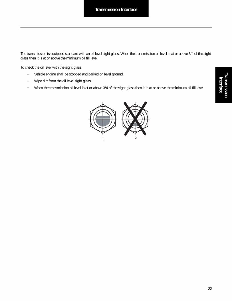
The transmission is equipped standard with an oil level sight glass. When the transmission oil level is at or above 3/4 of the sight glass then it is at or above the minimum oil fill level.
To check the oil level with the sight glass:
• Vehicle engine shall be stopped and parked on level ground.
• Wipe dirt from the oil level sight glass.
• When the transmission oil level is at or above 3/4 of the sight glass then it is at or above the minimum oil fill level.
1 2
23
Transmission Interface
Cooler RequirementsThe Fuller Advantage Automated Transmission is designed to operate without a cooler for some applications. For cooler-less operation requirements refer to TRAG2600.
Transmission Component Temperature RequirementsThe temperature limit for all electrical and air system components is 250 °F (121 °C). Do not exceed. If sufficient air gap between the heat source and these transmission components cannot be achieved, the OEM must provide proper methods of heat shielding to ensure this limit is not exceeded. The components and systems to be protected would include, but not limited to, the Shift Motors, Sensors, Solenoids, Air Filter Regulator, Wire Harness, Transmission Controller, Oil Cooler and Hoses, ECA, and the Transmission Case.
!

24
Transmission InterfaceTransm
ission Interface
Top View
Do not remove orattach anything toECU fastners
Lifting Eye
Lifting Eye
Neutral Switch
10 o’clockOutput Shaft
Speed Sensor
Reverse Switch
25
Electrical System Interface
Electrical Wiring Requirements
Note: “Power” refers to both Power Positive and Power Negative supply. (This is typically Battery Plus and Battery Negative.)
Note: “Switched Ignition” refers to power that is enabled with ignition key operation.
Note: Starting in November 2015 Automated transmissions began using the Generation 2 ECA which uses a Deutsch 2-Way power harness connector system. All references in this document pertain to the Generation ECA Power Pack.
Power Requirements• The vehicle shall have a negative ground power system.
• The vehicle primary power system shall be either of the following types: 12 or 24 volt.
• It is permissible to lose power to both the Transmission Control Module (TCM) and Electric Clutch Actuator (ECA) due to a single point disconnect, ONLY IF that same single point disconnect ALSO removes power to the Engine Control Module (ECM) simultaneously. (This is typically performed via a power distribution panel.)
• If a disconnect switch is used for the ECM, it shall be configured such that it also removes power to the TCM and ECA.
• The OEM shall provide power wiring to the TCM such that the differential voltage (TCM negative subtracted from TCM positive) under all operating conditions exceeds:
- 9 volts DC at a load of 30 amps as configured for a 12 volt base system.
- 18 volts DC at a load of 30 amps as configured for a 24 volt base system.
• The OEM shall provide power wiring to the transmission ECA such that the differential voltage (ECA positive minus ECA negative) under all operating conditions exceeds:
- 9 volts DC at a load of 40 amps as configured for a 12 volt base system
- 18 volts DC at a load of 40 amps as configured for a 24 volt base system.
• The OEM shall supply power to the TCM that does not exceed a steady state voltage of 32 volts DC.
• The OEM shall provide switched ignition power to the TCM such that it provides 10 amps at 12 volts DC.
• Power and switched ignition to the TCM shall not be switched off during the engine start process.
• The OEM shall include a Start Enable Relay.
Electrical Current Requirements - Operating Conditions over Temperature for 12-Volt Systems
• The Main Power 30 amp fuse connection for the TCM is required to be identified at the termination.
• The Switched Ignition 10 amp fuse connection for the TCM shall be identified at the termination.
• Operating current characteristics for the TCM:
• Active Shifting Current = 30 amps
• Maintaining current gear = 6 to 15 amps
• Power down sequence = 6 to 15 amps
• The ECA Main Power 40 amp fuse connection for the ECA is required to be identified at the termination. The continuous operating current of the ECA will not exceed 30 amperes.

26
Electrical System InterfaceElectrical System
Interface
Mating Connector and Terminal Requirements• Connectors shall be designed for use in the heavy-duty industry, conforming to SAE-J2030 and SAE-J1455.
• The OEM harness TCM mating connector shall be DRC26-38S01-P017 or equivalent. Mating Torque shall be 25 +/- 3 lbs. in. (2.82 +/- 0.33 Nm).
• The OEM harness ECA mating connector shall be Deutsch DTP06-2S-E003 or equivalent.
• Connectors shall be fully mated.
• Connector latches shall be completely locked.
• Unused Connectors and terminal cavities shall have sealed mating connectors or plugged.
• Gold plated terminals shall be used for signal circuits.
• The TCM Deutsch connector's size 12 pins shall be nickel plated terminals and used for power circuits.
• The TCM Deutsch connector's size 20 pins shall be gold plated terminals and used for signal circuits.
• The ECA Deutsch connector's size 12 pins shall be nickel plated terminals and used for power circuits.
Electrical Sealing RequirementsAll electrical junctures outside of the cab are required to be sealed per SAE-J2030 standards.
Network Communications Requirements• When the Eaton Push Button Shift Control is used, the Control Area Network (CAN) communications link between the
Shift Control and the Transmission Controller must follow J1939/15.
• The J1939 (the communications link between the Transmission TCM and the Engine Controller (ECM) shall follow SAE J1939 specifications for either J1939/11 or J1939/15.
• Shielded Twisted Pair (STP) per SAE J1939/11 or SAE J1587 accordingly.
• Unshielded Twisted Pair (UTP) per SAE J1939/15 or SAE J1587 accordingly.
• During all operating conditions, the voltage potential between TCM negative and ECA negative, measured at the control-lers, shall not exceed 2.0 volts DC.
Vehicle Service Requirements for Electronics
• Battery Positive and Negative must be disconnected PRIOR to any type of welding on any Fuller® Automated transmis-sion equipped vehicles.
• Battery Negative must be disconnected PRIOR to removal or installation of TCM harness connectors.
• Removal and / or replacement of a battery shall not disturb the terminating connectors of the TCM and ECA.
Auto Neutral Requirements
An auto neutral feature is provided with this transmission which forces the transmission into neutral in all instances when the parking brake is applied. This Requires the OEM to “T” a normally-closed pressure switch into the existing air line to the parking brake valve. Contact the brake manufacturer for pressure switch requirements. The pressure switch output and return wires are connected to the vehicle interface transmission TCM connector per the table in the “Connector Pin Descriptions” section. Start-ing with the release of software #5569892 it will be acceptable to use a J1939 Park brake signal in place of this switch. Refer to the table in the section SAE J1939 Data Link Received Messages.
27
Electrical System Interface
Start Enable Relay Requirements
Starting with the release of software #5569913 it will be acceptable to configure a vehicle for a J1939 Start Enable Type in place of a Start Enable Relay. A configurable Start Enable Type supports "Relay" or "J1939" control. The J1939 ETC7 SPN 2900 Trans-mission Crank Enable message may be used to enable cranking without a relay. This feature can be configured with VEPS or ServiceRanger 4.
Refer to the note included in the Typical Start Enable Relay Circuit and the EEC1 table in the section SAE J1939 Data Link Received Messages.
Remote Throttle Installation• Remote throttle applications shall be electrically interlocked by the transmission via an interlock relay with the high side
of the relay coil wired directly to pin V24 on the transmission TCM.
• The wiring shall be installed by the OEM or the bodybuilder if not already done by the OEM.
• The bodybuilder shall install the wiring such that it matches one of the options shown in the diagrams in the Aux Equip-ment Interface section.
• The bodybuilder shall verify proper operation prior to delivery to the customer.
Harness Routing Requirements• Harness and in-line connectors shall be anchored to prevent free movement. An anchor point shall be no further than 6
in. [15.24 cm] (Recommended 3 in. [7.62 cm]) from a connector. The length of an unanchored section of harness should be no more than 12 in. [30.48 cm].
• Eaton has provided several brackets that can be used for clipping vehicle components to. Do not mount additional com-ponents to TCM, transmission brackets, mounting studs, or lifting eyes under any circumstances. This includes cap screws used to fasten the shift bar housing, rear housing, bearing covers, and PTO covers. Removal of these can com-promise transmission system operation and overall system reliability.
• Tie wrap application and tightness shall conform to Section 14.1.1 of IPC/WHMA-A-620 “Requirements and Acceptance for Cable and Wire Harness Assemblies”, January 2002 revision or later. Tie wrap application shall meet the Target and Defect of a Class 3 product per IPC/WHMA-A-620. Use tie wraps on harness covering only, not individual wires. Do not anchor harness with tie wraps in contact with wire insulation. Tie wraps shall not pull on the harness so that connector cable seals are distorted. Allow cable to exit connector body with out pulling on the connector.
• A bend radius of six times the harness diameter is recommended.
• Recommended use of the fixed clip points on OEM harness - Fir trees, J-clips, P-clips.
• Harness routing shall not interfere with oil fill plugs, sensor locations, or manufacturing fixtures.

28
Electrical System InterfaceElectrical System
Interface
Vehicle InterfaceConnector
Transmission InterfaceConnector
For TemperatureSensing Unit
593 mm[23.4 "]

29
Electrical System Interface
Use for vehicle Harness TiedownThese are NOT lifting eyes
Use for vehicle Harness TiedownThese are NOT lifting eyes
Use for vehicle Harness TiedownThese are NOT lifting eyes
Use for ECA PowerHarness Tiedown

30
Electrical System InterfaceElectrical System
Interface
Electrical Wiring Recommendations
Contact Lubrication RecommendationNote: Eaton recommends the use of (NyoGel 760G) on all electrical contacts. The preferred method of application is to use a
metered dispensing mechanism that places the material on the socket of the connector. It is also preferred that the mate-rial be placed immediately prior to connector mating to reduce the probability of contamination.
• For further information contact your Eaton OEM Engineering Support Group.
• The NyoGel 760G material shall not be applied to the transmission ECU 38-Way (Vehicle Interface) connector jack-screw. No anti-seize, lubricating, or foreign compound shall be applied to the connector jackscrew threads. The use of such compounds may affect jackscrew torque and prevent proper sealing of the connector.
Harness Design Recommendations
The cable for the Deutsch connector (DRC26-38-S01) should be:
• 18 GXL max /18 TXL min. for Communication and control wires
• 12 GXL or 14 SXL for Power Supply wires
• 12 GXL or 14 SXL for V-Ignition wires
The cable for the 2-Way Deutsch connector should be:
• 10 GXL for Power Supply wires to ECA
The cable for the 8-Way Deutsch connector shall be:
• 18 GXL max 18 TXL min. for Communication and control wires to ECA
• 18 GXL for V-Ignition wires
Note: These sizes ensure proper connector sealing and current carrying capacity.
• Splices must be ultrasonically welded per IPC/WHMA-A-620 and encapsulated and sealed to meet SAE-J1455.
• Convoluted Conduit shall have a service temperature of at least 257° F (125° C).
• Braided Loom shall have a service temperature of at least 280° F (138° C). Coverage: A minimum of 10 / maximum of 12 picks per inch. TWISTED CABLES
• 2 Cables = 10 Twists / 25.4 cm
• 3 Cables = 8 Twists / 25.4 cm
• (16 and 18 Gage Cable Only)
Overcurrent Protection Recommendations
All wiring and overcurrent protection, at a minimum, should meet the requirements of Caltrans Division of Equipment Quality Assurance Standard – Electric (2004), Section 3.

31
Electrical System Interface
SAE Wire SAE Wire Nominal Outside Diameter (mm) Nominal Outside Diameter Inch
Size mm² Size No. TXL GXL SXL TXL GXL SXL
0.8 18 1.98 2.39 2.72 0.08 0.09 0.11
1 16 2.24 2.59 3.05 0.09 0.10 0.12
2 14 2.62 2.97 3.58 0.10 0.12 0.14
3 12 3.25 3.63 4.14 0.13 0.14 0.16
5 10 3.96 4.45 4.95 0.16 0.18 0.20
Cable Connector (Deutsch) - DRC26-38S01-P017
Seal Range (mm) / (in)
Contact Size Description Cable Diameter Min(mm²)
Cable Diameter Max(mm²)
TXL GXL SXL
1.02 - 2.41 /.040 -.095 20 Signal 1.02 2.41 18 18 NR
3.40 - 4.95 /.134 -.195 12 Power 3.40 4.95 NR 12 NR
3.40 - 4.95 /.134 -.195 12 V-Ignition 3.40 4.95 NR 12 14
Cable Connector (Deutsch) - 2-Way DTM06-08SA-E003
Seal Range (mm) / (in) Contact Size Description Cable Diameter MIn(mm²)
Cable Diameter Max(mm²)
TXL GXL SXL
4.40 - 5.15 /.173 -.202 10 Power (ECA) 4.40 5.15 NR NR 10
Cable Connector Back Shell (Deutsch) - 38-Way DRC series
Back Shell (Deutsch) *Low Profile Backshell (Deutsch)
Part Number 0528-004-3805 0528-005-3805
Conduit/OEM Packard Packard
Conduit P/N *(R-69246 round) Con-voluted Tubing; Size 13 mm [.500]; 125° C or higher temperature rating
(R-72506 profile) *(R-69246 round) Con-voluted Tubing; Size 13 mm [.500]; 125° C or higher temperature rating
32
Electrical System InterfaceElectrical System
Interface
Electrical Juncture Recommendations• Do not use more than three (3) ring terminals per mounting stud. Terminals such as ring, bullet, spade, etc., shall be
sized for the correct current capacity of the circuit as stated by the manufacturer. Terminals shall be plated and non insulated. Sleeves shall be insulated with a double wall shrink tubing. Sealing Dielectric grease over the top of the ring is recommended.
• Do not use Lock washers or Star washers for contact surfaces.
• Crimps shall be applied with a tool specified by the manufacturer of the terminal and in accordance to the manufac-turer's specifications.
Harness Troubleshooting Recommendations and Test Equipment Design• Removal of fuses is not recommended as the method of disconnecting power from the TCM. Making and breaking a cir-
cuit through tin plated terminals (e.g. ring terminals, fuses, and most connectors) will destroy the plating on the termi-nal. Opening a switch contact or the main power link is the recommended method of interrupting power.
• Harness Probing Damage Alert - Never puncture cable insulation with a probe to verify voltage or to check continuity. Damage to the wire insulation can lead to immediate or future failures of the harness or electronic control unit due to short circuits, water entry, or corrosion.
Note: If a connection to the harness or TCM is required before vehicle installation, Eaton recommends the use of a connector with a spring loaded contact rather than a standard mating connector. The spring loaded contact is intended to make the electrical connection with the tip of the terminal without touching the mating surface. This will protect the terminal plating, the NyoGel 760G™ and retain the original durability and reliability of the connector system.
33
Electrical System Interface
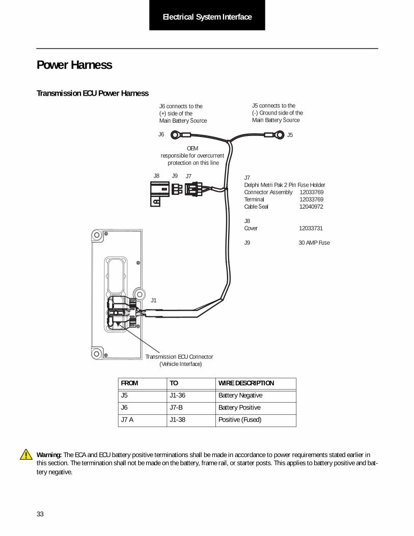
Power Harness
Transmission ECU Power Harness
Warning: The ECA and ECU battery positive terminations shall be made in accordance to power requirements stated earlier in this section. The termination shall not be made on the battery, frame rail, or starter posts. This applies to battery positive and bat-tery negative.
FROM TO WIRE DESCRIPTION
J5 J1-36 Battery Negative
J6 J7-B Battery Positive
J7 A J1-38 Positive (Fused)
J6 connects to the (+) side of the Main Battery Source
J5 connects to the (-) Ground side of the Main Battery Source
J6 J5
J8 J9
Transmission ECU Connector (Vehicle Interface)
J1
J7Delphi Metri Pak 2 Pin Fuse HolderConnector Assembly 12033769Terminal 12033769Cable Seal 12040972
J8Cover 12033731
J9 30 AMP Fuse
J7
OEM responsible for overcurrent
protection on this line
!

34
Electrical System InterfaceElectrical System
Interface
Electric Clutch Actuator (ECA) Power Harness
FROM TO WIRE DESCRIPTION
J7-A J1-C (ECA) Battery Positive (Fused)
J6 J7-B Battery Positive
J5 J1-B (ECA) Battery Negative
J6 connects to the (+) 12 Volt side of the Main Battery Source
J5 connects to the (-) Ground side of the Main Battery Source
J6 J5
OEM responsible for overcurrent
protection on this line
J7 J9 J8
Fuse holder used by Eaton in development Vehicles
40 Amp fuseLITTLEFUSE 152 SERIESMaxi Fuse Splashproof Holder for 20-70 Amp
Part Number Description:
152007Z Cover with Integral seal1520006Z Body without Mounting Tabs868-096 Gray Wire Seal for 4-10mm^2 (10-8AWG) Wire913-068 Single terminal 4-6mm^2 (10AWG) Wire
J1

35
Electrical System Interface
Warning: The ECA and ECU battery positive terminations shall be made in accordance to power requirements stated earlier in this section. The termination shall not be made on the battery, frame rail, or starter posts. This applies to battery positive and bat-tery negative.
2-WAY ECA CONNECTOR PIN OUT
1 Battery Negative
2 Battery Positive (Fused)
12
!
36
Electrical System InterfaceElectrical System
Interface
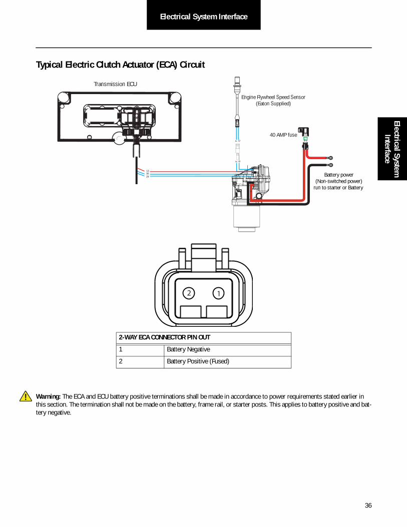
Typical Electric Clutch Actuator (ECA) Circuit
Warning: The ECA and ECU battery positive terminations shall be made in accordance to power requirements stated earlier in this section. The termination shall not be made on the battery, frame rail, or starter posts. This applies to battery positive and bat-tery negative.
2-WAY ECA CONNECTOR PIN OUT
1 Battery Negative
2 Battery Positive (Fused)
Transmission ECU
3029
F GF G
40 AMP fuse
Battery power(Non-switched power)
run to starter or Battery
B C
13
Engine Flywheel Speed Sensor(Eaton Supplied)
12
!

37
Electrical System Interface
Ignition Circuit Detail
Transmission ECU Ignition Circuit
Note: Battery and Ignition power and ground to the TECU shall not be switched off during the engine start process.
FROM TO
J1-35 VIGN
10 AMP onlyManual resettingcircuit breaker
10 AMPfuseOr
35
23
17
31
24 25
29 30
15 16
26
20
34
27 28
32 33
18 19
7
3
8 9
1 2
10
6
11 12
4 5
2221
38
36
37
13 14
35
Front ViewTransmission ECU Connector
(Vehicle Interface)
Transmission ECU Connector (Vehicle Interface)
J1 Ignition Key Switch
Run to main power lead thatfeeds the ignition bus (OEM responsible for overcurrent
protection on this line)
38
Electrical System InterfaceElectrical System
Interface
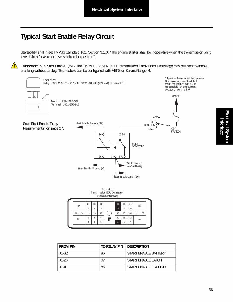
Typical Start Enable Relay Circuit
Startability shall meet FMVSS Standard 102, Section 3.1.3: “The engine starter shall be inoperative when the transmission shift lever is in a forward or reverse direction position”.
Important: J939 Start Enable Type - The J1939 ETC7 SPN 2900 Transmission Crank Enable message may be used to enable cranking without a relay. This feature can be configured with VEPS or ServiceRanger 4.
FROM PIN TO RELAY PIN DESCRIPTION
J1-32 86 START ENABLE BATTERY
J1-26 87 START ENABLE LATCH
J1-4 85 START ENABLE GROUND
!
Use Bosch: Relay : 0332-209-151 (+12 volt), 0332-204-203 (+24 volt) or equivalent
Mount : 3334-485-008Terminal : 1901-355-917
86 30
85 87a87
Start Enable Battery (32)
Run to StarterSolenoid Relay
+BATT
KEYSWITCH
ACC
OFF
START
Relay Schematic
Start Enable Latch (26)
Start Enable Ground (4)
Front View
23
17
31
24 25
29 30
15 16 20
34
27 28
33
18 19
7
3
8 9
1 2
10
6
11 12
5
2221
38
36
37
13 14
35
32
26
4
* Ignition Power (switched power)Run to main power lead thatfeeds the ignition bus (OEM responsible for overcurrent protection on this line)
Transmission ECU Connector (Vehicle Interface)
IGNITIONSee “Start Enable Relay Requirements” on page 27.

39
Component and System Diagrams
Typical System with Eaton Push Button
Note: Cinch is an equivalent.
When the Eaton Push Button Shift Control is used the CAN (Control Area Network communications link between the Shift Control and the Transmission Controller) must be a J1939/15 twisted pair cable.
PackardConnector 12048455Terminal 12103881Plug 12034413
FROM TO DESCRIPTION
J1-27 C2-F2 HIL LOW (Proprietary CAN)
J1-28 C2-F1 HIL HIGH (Proprietary CAN)
J1-25 C2-J3 Shift Control Power Minus
J1-31 C2-C1 Shift Control Power Plus
C2-B3 Dimmer Control Input
27282531
31
24 25
29 30
15 16
26
20
34
27 28
32 33
18 19
7
3
8 9
1 2 6
11 12
4 5
2221
38
36
37
13 14
3510
17
23
Front ViewTransmission ECU Connector
(Vehicle Interface)
Dimmer control input
Push Button Shift Control
Push Button Control30-way connector
C2 F 2 F 1 J 3 C 1 B 3
Bulkhead connectorlocated at firewall
A1
A2
A3
B1
B3C3
D1
D2
D3
E1
E2
E3F3
H1
H2
H3
Front ViewShift Control (30-Way Connector)
B2C2
K3
J1K1
K2
G1
G2
G3
J2
C1
J3
F2
F1
40
Electrical System InterfaceElectrical System
Interface
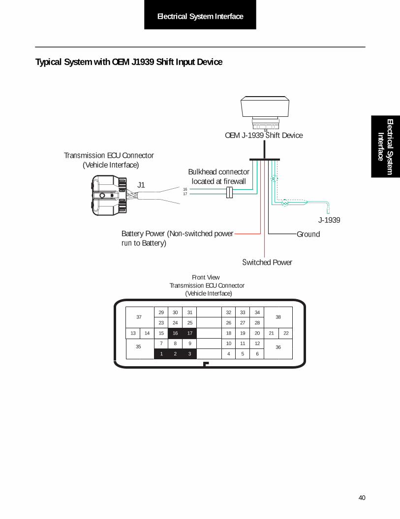
Typical System with OEM J1939 Shift Input Device
23
17
31
24 25
29 30
15 16
26
20
34
27 28
32 33
18 19
7 8 9
2
10
6
11 12
4 5
2221
38
36
37
13 14
351 3
Transmission ECU Connector (Vehicle Interface)
Front View
J1
OEM J-1939 Shift Device
Bulkhead connectorlocated at firewall
J-1939
Transmission ECU Connector (Vehicle Interface)
1617
Switched Power
GroundBattery Power (Non-switched powerrun to Battery)

41
Electrical System Interface
Typical System with OEM Supplied Resistive Ladder Shift Device
OEM supplied Shift Lever shall have gated positions per Eaton engineering specification. If an OEM supplied resistive ladder type shift lever is used in conjunction with a J1939 gear display, Eaton recommends the service lamp connector is located close to the 6 or 9-pin diagnostic connector
FROM TO DESCRIPTION
J1-15 F2-B Shift Control Input (Mode Auto)
J1-16 F2-A Shift Control Input (Mode Manual)
J1-17 F2-C Shift Control Input (Mode Common)
J1-23 F3-A Service Lamp Output
F3-B Ground
15161723
B A C
B A C
OEM Shift Lever
Service LampConnector
2-Way ConnectorOEM can select
F2
F3
Transmission ECU Connector (Vehicle Interface)
42
Electrical System InterfaceElectrical System
Interface
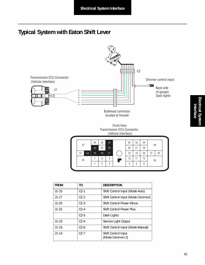
Typical System with Eaton Shift Lever
FROM TO DESCRIPTION
J1-15 C2-1 Shift Control Input (Mode Auto)
J1-17 C2-2 Shift Control Input (Mode Common)
J1-25 C2-3 Shift Control Power Minus
J1-31 C2-4 Shift Control Power Plus
C2-5 Dash Lights
J1-23 C2-6 Service Light Output
J1-16 C2-8 Shift Control Input (Mode Manual)
J1-14 C2-7 Shift Control Input (Mode Common 2)
25311516172314
31
24 25
29 30
15 16
26
20
34
27 28
32 33
18 19
7
3
8 9
1 2 6
11 12
4 5
22 21
38
36
37
13 14
35 10
17
23
Front View Transmission ECU Connector
(Vehicle Interface)
J1
C2
Bulkhead connector located at firewall
3 4 1 8 2 6 5 7 3 4 1 8 2 6 5 7
Back side of gauges Dash lights
Dimmer control input Transmission ECU Connector
(Vehicle Interface)
14

43
Electrical System Interface
Dimmer Control Input Connection
Note: Connect VDASH to the dash lights. This input will dim the lights on the shift device when the lights are on. When VDASH input is off, the lights on the shift device will be on full.
Shift Control FROM TO
Cobra Lever C2-5 VDASH
Push Button B3 VDASH
Bulkhead connectorlocated at firewall
Back side of gaugesDash lights
Dimmer control input
Push Button Shift Control
Push Button Control30-way connector
F2 F1 J3 C1 B3
C2
Bulkhead connectorlocated at firewall
3 4 1 8 2 6 5 73 4 1 8 2 6 5 7
Back side of gaugesDash lights
Dimmer control input

44
Electrical System InterfaceElectrical System
Interface
Diagnostic ConnectorThe diagnostic connector (9-pin required) shall be easily accessible and mounted on the drivers side of the cab.
Note: SAE has one approved connector. Eaton requires the Deutsch 9-pin.
FROM TO 9-PIN DESCRIPTION
J1-10 F J-1587 +
J1-11 G J-1587 -
__ B BATTERY +
__ A GROUND -
__ C J1939 HIGH
__ D J1939 LOW
+ Battery
For Transmission Diagnostics
J-1587 Data Link
1011
CDBFGA
9-way
AF
J
E
GH
DC
B
23
17
31
24 25
29 30
15 16
26
20
34
27 28
32 33
18 19
7
3
8 9
1 2 6
12
4 5
2221
38
36
37
13 14
3510 11
J1
Front ViewTransmission ECU Connector
(Vehicle Interface)
J-1939 Low
J-1939 High
Transmission ECU Connector
(Vehicle Interface)

45
Electrical System Interface
J1939/15 Data Link
The communications link between the Transmission ECU and the Engine Controller ECM shall follow SAE J1939 specifications for either J1939/11 or J1939/15.
• Maximum 40 meter Length.
• Maximum 1 meter stub length.
• Maximum 10 modules on segment.
• Twisted pair (18 gauge) with 1 twist per inch.
• 120 Ohm terminating resistors shall be used.
The third pin for shield is not used with in-line and T-connectors.
Note: The distance between the TECU and Engine ECU should be as short a possible.
FROM TO DESCRIPTION
J1-2 B J1939 Low
J1-3 A J1939 High
J1-1 C J1939 Shield (used only for SAE J1939/11)
TerminatingResistorJ-1939/15 data link
(OEM supplied)
TerminatingResistor
Other Modules
J1
Engine ECU TransmissionECU
23
17
31
24 25
29 30
15 16
26
20
34
27 28
32 33
18 19
7 8 9
2
10
6
11 12
4 5
2221
38
36
37
13 14
351 3
Transmission ECU Connector (Vehicle Interface)
1

46
Electrical System InterfaceElectrical System
Interface
J1939/15 Data Link Specifications
Engine ECU
A
B
C
D
E
Ref. Body Signal Terminals (QTY)
A
D
AA
A
B B
Wedge
CC
DTM-06-2S
DTM-06-2S
DTM04-2P-P007
DTM06-2S-EP10
DTM04-2P
Function
Through Connector
Stub Connector
"T" Receptacle
120 Ohm Termination
ECU Receptacle
0462-201-2031 (2)
0462-201-2031 (2)
N/A
0460-202-2031 (2)
WM-2S
WM-2SB
N/A
N/A
WM-2SB
WM-2P
1.00 MeterMax Length
1.00 MeterMax Length
40.00 MeterMax Length
TransmissionECU
B
C D
Other Modules
Recommended Cable Manufacturer
Cable Part Number Round
J-1939 (+)(PIN "A")Color
J-1939 (-)(PIN "B")Color
Champlain J1939/15 Yes Yellow Green
Twisted PairJ1939 (+)J1939 (+)
J1939 (-)J1939 (-)

47
J1939 Broadcast Messages
SAE J1939 Data Link Broadcast Messages
Fuller Advantage Automated Transmissions interface with many different components installed on the vehicle such as engine, shift input device, gear display, and service lamp. SAE J1939 and J1587 data links are standard means to transfer data to other components. Successful system integration is essential to ensure the utmost satisfactory operation of the vehicle. The following sections summarize the system integration requirements.
SPNs listed below are standard on Fuller Advantage Automated Transmissions. Unused data in a PGN is broadcast as “Not Available.” The inability the transmission control unit to broadcast valid data will result in “Error Indicator” or “Not Available” being broadcast. For specific message formatting and broadcast rate see SAE J1939-71 and SAE J1939-73.
Active Diagnostic Trouble Codes (DM1) PGN 65226
Source Address: 3 (Transmission #1)
Parameter Name SPN
Malfunction Indicator Lamp Status 1213
Red Stop Lamp Status 623
Amber Warning Lamp Status 624
Protect Lamp Status 987
Flash Engine Malfunction Indicator Lamp 3038
Flash Engine Red Stop Lamp 3039
Flash Engine Amber Warning Lamp 3040
Flash Engine Protect Lamp 3041
Suspect Parameter Number 1214
FMI 1215
SPN Conversion Method 1706
Occurrence Count 1216

48
J1939 Broadcast MessagesJ1939 Broadcast
Messages
Previously Active Diagnostic Trouble Codes (DM2)
PGN 65226
Source Address: 3 (Transmission # 1)
Parameter Name SPN
Malfunction Indicator Lamp Status 1213
Red Stop Lamp Status 623
Amber Warning Lamp Status 624
Protect Lamp Status 987
Flash Engine Malfunction Indicator Lamp 3038
Flash Engine Red Stop Lamp 3039
Flash Engine Amber Warning Lamp 3040
Flash Engine Protect Lamp 3041
Suspect Parameter Number 1214
FMI 1215
SPN Conversion Method 1706
Occurrence Count 1216
Electronic Transmission Controller 1 (ETC1) PGN 61442
Source Address: 3 (Transmission # 1)
Parameter Name SPN
Transmission Driveline Engaged 560
Transmission Shift In Process 574
Transmission Output Shaft Speed 191
Engine Momentary Overspeed Enable 606
Progressive Shift Disable 607
Transmission Input Shaft Speed 161
Electronic Transmission Controller 2 (ETC2) PGN 61445
Source Address: 3 (Transmission # 1)
Parameter Name SPN
Transmission Selected Gear 524
Transmission Actual Gear Ratio 526
Transmission Current Gear 523
Transmission Requested Range 162
Transmission Current Range 163

49
J1939 Broadcast Messages
Electronic Transmission Controller 7 (ETC7) PGN 65098
Source Address: 3 (Transmission # 1)
Parameter Name SPN
Transmission Ready for Brake Release 3086
Transmission Engine Crank Enable 2900
Transmission Requested Gear Feedback 3289
Transmission Warning Indicator 5344
Transmission Mode 1 Indicator 2536
Transmission Mode 3 Indicator 2538
Trans Fluids 2 (TRF2) PGN 64917
Source Address: 3 (Transmission # 1)
Torque / Speed Control 1 (TSC1) Engine PGN 0
Source Address: 3 (Transmission # 1)
Parameter Name SPN
Engine Override Control Mode 695
Engine Requested Speed Control Conditions 696
Override Control Mode Priority 897
Engine Requested Speed/Speed Limit 898
Engine Requested Torque/Torque Limit 518
Message Counter 4206
Message Checksum 4207
Torque / Speed Control 1 (TSC1) Retarder PGN 0
Source Address: 3 (Transmission # 1)
Parameter Name SPN
Engine Override Control Mode 695
Engine Requested Speed Control Conditions 696
Override Control Mode Priority 897
Engine Requested Torque/Torque Limit 518
Message Counter 4206
Message Checksum 4207

50
J1939 Broadcast MessagesJ1939 Broadcast
Messages
Broadcast On Request To Transmission
Component Identification (CI) PGN 65259
Source Address: 3 (Transmission # 1)
Parameter Name SPN
Make 586
Model 587
Serial Number 588
Unit Number (Power Unit) 233
Electronic Transmission Controller 3 (ETC3) PGN 65223
Source Address: 3 (Transmission # 1)
Parameter Name SPN
Transmission Shift Finger Gear Position 59
Transmission Shift Finger Rail Position 60
Transmission Shift Finger Rail Actuator 1 772
Transmission Shift Finger Gear Actuator 1 773
Transmission Range High Actuator 768
Transmission Range Low Actuator 769
Transmission Splitter Direct Actuator 770
Transmission Splitter Indirect Actuator 771
Transmission Inertia Brake Actuator 787
Electronic Transmission Controller 4 (ETC4) PGN 65221
Source Address: 3 (Transmission # 1)
Parameter Name SPN
Transmission Synchronizer Brake Value 54
Software Identification (SOFT) PGN 65242
Source Address: 3 (Transmission # 1)
Parameter Name SPN
Number of Software Identification Fields 965 965
Software Identification 234 234
51
J1939 Broadcast Messages
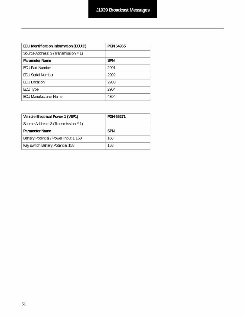
ECU Identification Information (ECUID) PGN 64965
Source Address: 3 (Transmission # 1)
Parameter Name SPN
ECU Part Number 2901
ECU Serial Number 2902
ECU Location 2903
ECU Type 2904
ECU Manufacturer Name 4304
Vehicle Electrical Power 1 (VEP1) PGN 65271
Source Address: 3 (Transmission # 1)
Parameter Name SPN
Battery Potential / Power Input 1 168 168
Key switch Battery Potential 158 158

52
J1939 Received MessagesJ1939 Received
Messages
SAE J1939 Data Link Received Messages
Fuller Advantage Automated Transmissions interface with many different components installed on the vehicle such as engine, shift input device, gear display, and service lamp. SAE J1939 and J1587 data links are standard means to transfer data to other components. Successful system integration is essential to ensure the utmost satisfactory operation of the vehicle. The following sections summarize the system integration requirements.
For specific message formatting and broadcast rate see SAE J1939-71 and SAE J1939-73.
Cruise Control / Vehicle Speed (CCVS) PGN 65265
Source Address: 49 (Cab Controller - Primary), 0 (Engine #1), 17 (Cruise Control), 23 (Instrument Cluster #1), 33 (Body Con-troller), 39 (Management Computer)
Note: For each signal in the CCVS message, the first Source address that is supported and has valid data is latched for the power cycle. Address then that sending Brake Switch data.
Parameter Name SPN
Parking Brake Switch 70
Wheel-Based Vehicle Speed 84
Brake Switch 597
Component Identification (CI) PGN 65259
Source Address: 5 (Shift Console – Primary)
Note: The accepted CI shall be defined as Model type “RNDML”. “RNDML” shall be the first Model characters received by the requester. Additional Model information shall be separated by a dash (RNDML-XXXX).
Parameter Name SPN
Make 586
Model 587
Serial Number 588
Unit Number (Power Unit) 233
PTO Drive Engagement (PTODE) PGN 64932
Source Address: For the output shaft PTO engagement status SPN, the first source address that has valid data is latched.
Parameter Name SPN
Output Shaft PTO Engagement Status 3462
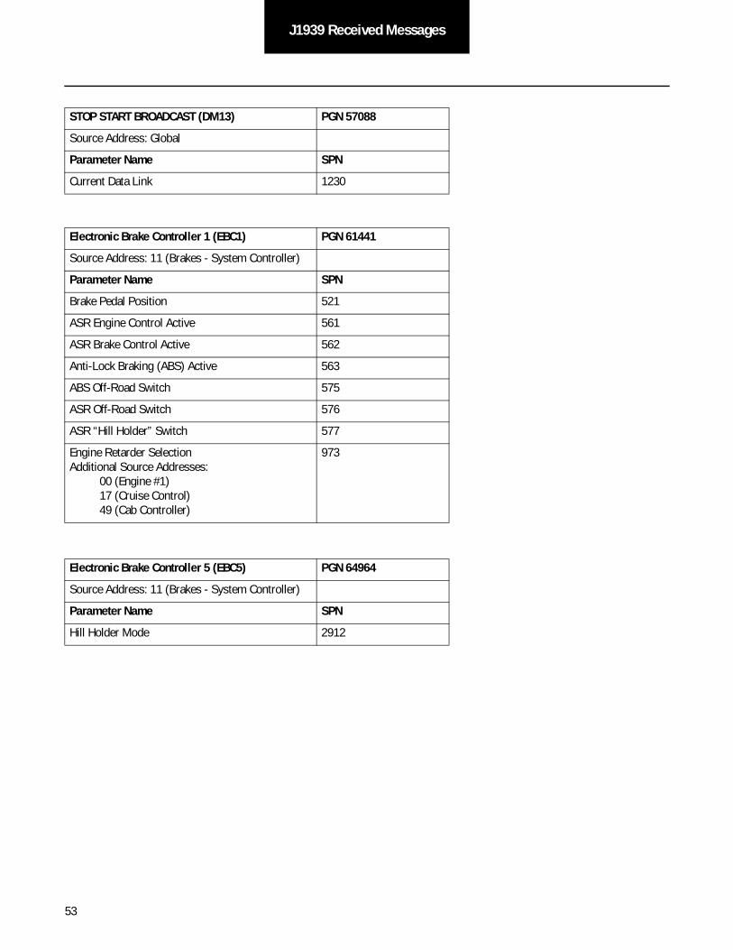
53
J1939 Received Messages
STOP START BROADCAST (DM13) PGN 57088
Source Address: Global
Parameter Name SPN
Current Data Link 1230
Electronic Brake Controller 1 (EBC1) PGN 61441
Source Address: 11 (Brakes - System Controller)
Parameter Name SPN
Brake Pedal Position 521
ASR Engine Control Active 561
ASR Brake Control Active 562
Anti-Lock Braking (ABS) Active 563
ABS Off-Road Switch 575
ASR Off-Road Switch 576
ASR “Hill Holder” Switch 577
Engine Retarder Selection Additional Source Addresses: 00 (Engine #1) 17 (Cruise Control) 49 (Cab Controller)
973
Electronic Brake Controller 5 (EBC5) PGN 64964
Source Address: 11 (Brakes - System Controller)
Parameter Name SPN
Hill Holder Mode 2912
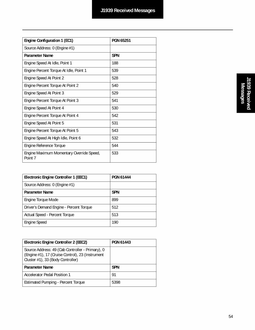
54
J1939 Received MessagesJ1939 Received
Messages
Engine Configuration 1 (EC1) PGN 65251
Source Address: 0 (Engine #1)
Parameter Name SPN
Engine Speed At Idle, Point 1 188
Engine Percent Torque At Idle, Point 1 539
Engine Speed At Point 2 528
Engine Percent Torque At Point 2 540
Engine Speed At Point 3 529
Engine Percent Torque At Point 3 541
Engine Speed At Point 4 530
Engine Percent Torque At Point 4 542
Engine Speed At Point 5 531
Engine Percent Torque At Point 5 543
Engine Speed At High Idle, Point 6 532
Engine Reference Torque 544
Engine Maximum Momentary Override Speed, Point 7
533
Electronic Engine Controller 1 (EEC1) PGN 61444
Source Address: 0 (Engine #1)
Parameter Name SPN
Engine Torque Mode 899
Driver’s Demand Engine - Percent Torque 512
Actual Speed - Percent Torque 513
Engine Speed 190
Electronic Engine Controller 2 (EEC2) PGN 61443
Source Address: 49 (Cab Controller - Primary), 0 (Engine #1), 17 (Cruise Control), 23 (Instrument Cluster #1), 33 (Body Controller)
Parameter Name SPN
Accelerator Pedal Position 1 91
Estimated Pumping - Percent Torque 5398
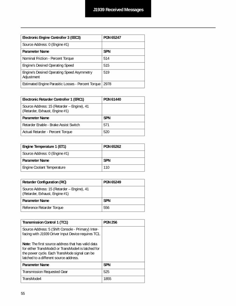
55
J1939 Received Messages
Electronic Engine Controller 3 (EEC3) PGN 65247
Source Address: 0 (Engine #1)
Parameter Name SPN
Nominal Friction - Percent Torque 514
Engine’s Desired Operating Speed 515
Engine’s Desired Operating Speed Asymmetry Adjustment
519
Estimated Engine Parasitic Losses - Percent Torque 2978
Electronic Retarder Controller 1 (ERC1) PGN 61440
Source Address: 15 (Retarder – Engine), 41 (Retarder, Exhaust, Engine #1)
Parameter Name SPN
Retarder Enable - Brake Assist Switch 571
Actual Retarder - Percent Torque 520
Engine Temperature 1 (ET1) PGN 65262
Source Address: 0 (Engine #1)
Parameter Name SPN
Engine Coolant Temperature 110
Retarder Configuration (RC) PGN 65249
Source Address: 15 (Retarder – Engine), 41 (Retarder, Exhaust, Engine #1)
Parameter Name SPN
Reference Retarder Torque 556
Transmission Control 1 (TC1) PGN 256
Source Address: 5 (Shift Console - Primary) Inter-facing with J1939 Driver Input Device requires TC1.
Note: The first source address that has valid data for either TransMode3 or TransMode4 is latched for the power cycle. Each TransMode signal can be latched to a different source address.
Parameter Name SPN
Transmission Requested Gear 525
TransMode4 1855
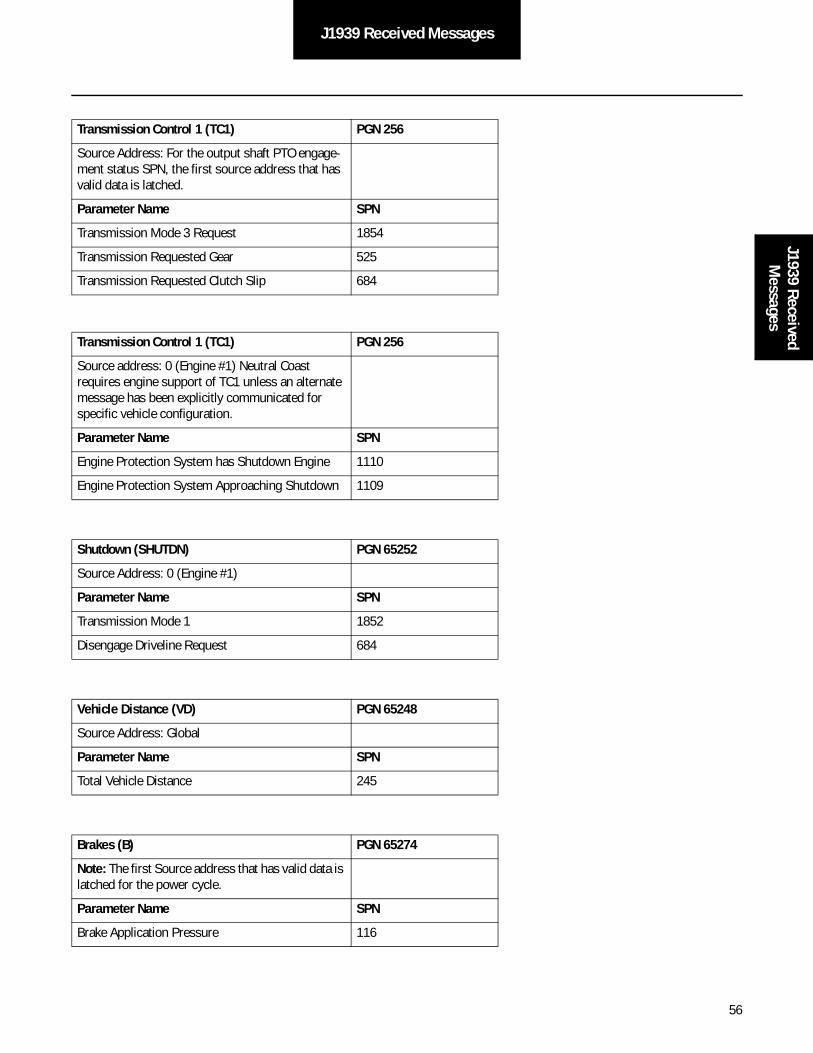
56
J1939 Received MessagesJ1939 Received
Messages
Transmission Control 1 (TC1) PGN 256
Source Address: For the output shaft PTO engage-ment status SPN, the first source address that has valid data is latched.
Parameter Name SPN
Transmission Mode 3 Request 1854
Transmission Requested Gear 525
Transmission Requested Clutch Slip 684
Transmission Control 1 (TC1) PGN 256
Source address: 0 (Engine #1) Neutral Coast requires engine support of TC1 unless an alternate message has been explicitly communicated for specific vehicle configuration.
Parameter Name SPN
Engine Protection System has Shutdown Engine 1110
Engine Protection System Approaching Shutdown 1109
Shutdown (SHUTDN) PGN 65252
Source Address: 0 (Engine #1)
Parameter Name SPN
Transmission Mode 1 1852
Disengage Driveline Request 684
Vehicle Distance (VD) PGN 65248
Source Address: Global
Parameter Name SPN
Total Vehicle Distance 245
Brakes (B) PGN 65274
Note: The first Source address that has valid data is latched for the power cycle.
Parameter Name SPN
Brake Application Pressure 116

57
J1939 Received Messages
Received On Request From Transmission
Time / Date (TD) PGN 65254
Source Address: Global
Parameter Name SPN
Seconds 959
Minutes 960
Hours 961
Month 963
Day 962
Year 964
Local minute offset 1601
Local hour offset 1602

58
J1587 Broadcast MessagesJ1587 Broadcast
Messages
SAE J1587 Data Link Broadcast Messages
Note: All messaging protocol shown on this page are new to this product family.
Note: Unused data in a PID is broadcast as “Not Available.” Reference SAE J1587 for complete specification.
Broadcast Period Parameter Name PID
100 ms Transmission Output Shaft Speed 191
400 ms Text Message to Display Note: PID 226 controls the tone. Cadence of the tone is controlled by Gen 3.
226
500 ms Transmission Range Selected 162
Transmission Range Attained 163
1.0 s Battery Potential (Voltage) 168
Upon change or 15 s while fault active
Transmitter System Diagnostic Code and Occurrence Count Table 194
On Request Clutch Cylinder Position 33
Transmission Synchronizer Brake Value 54
Transmission Actuator Status #2 57
Shift Finger Actuator Status 58
Shift Finger Gear Position 59
Shift Finger Rail Position 60
Transmission Actuator Status #1 63
Vehicle Enabling Component Status 66
Shift Request Shift Status 67
Battery Potential (Voltage) - Switched 158
Transmission Main Shaft Speed 160
Transmission Input Shaft Speed 161
Engine Speed 190
Multi-Section Parameter 192
Diagnostic Data Request/Clear Count 195
Diagnostic Data/Count Clear Response 196
Software Identification 234
Component Identification Parameter 243
Total Vehicle Hours 246
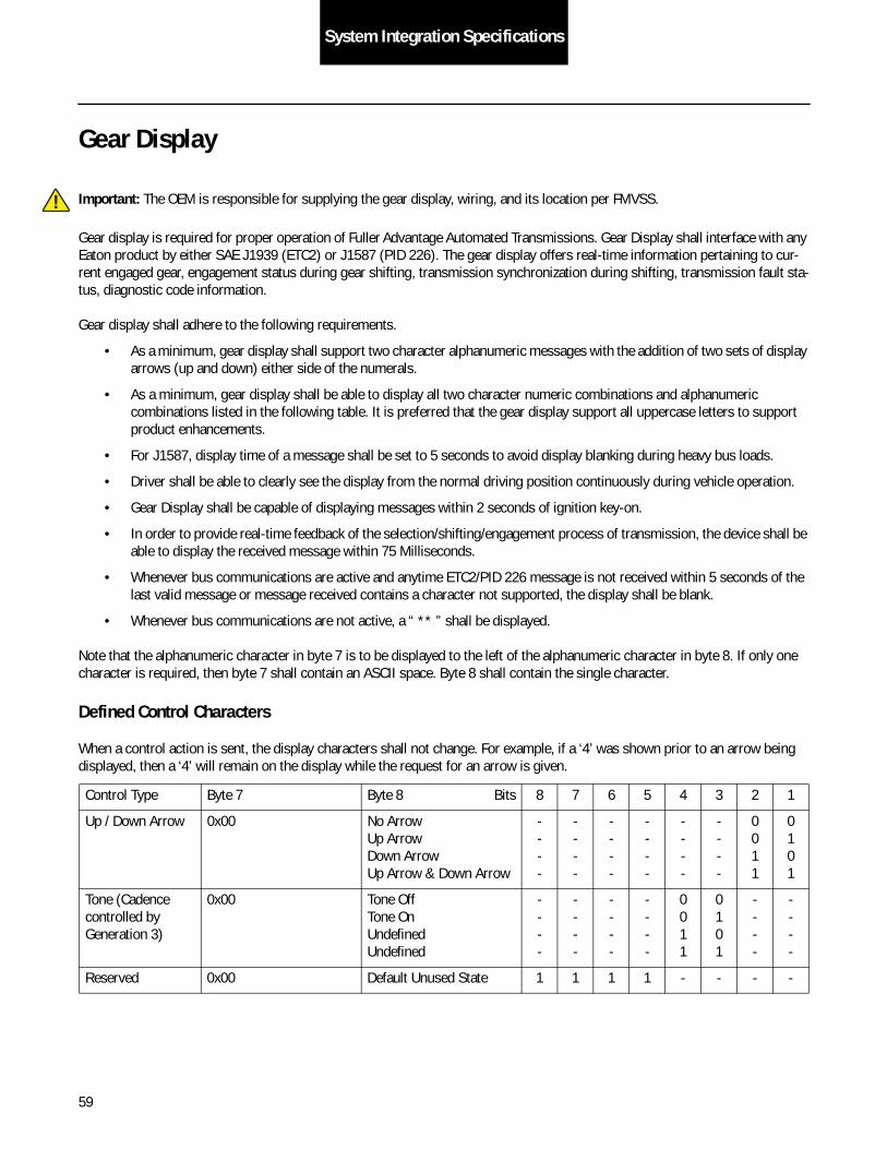
59
System Integration Specifications
Gear Display
Important: The OEM is responsible for supplying the gear display, wiring, and its location per FMVSS.
Gear display is required for proper operation of Fuller Advantage Automated Transmissions. Gear Display shall interface with any Eaton product by either SAE J1939 (ETC2) or J1587 (PID 226). The gear display offers real-time information pertaining to cur-rent engaged gear, engagement status during gear shifting, transmission synchronization during shifting, transmission fault sta-tus, diagnostic code information.
Gear display shall adhere to the following requirements.
• As a minimum, gear display shall support two character alphanumeric messages with the addition of two sets of display arrows (up and down) either side of the numerals.
• As a minimum, gear display shall be able to display all two character numeric combinations and alphanumeric combinations listed in the following table. It is preferred that the gear display support all uppercase letters to support product enhancements.
• For J1587, display time of a message shall be set to 5 seconds to avoid display blanking during heavy bus loads.
• Driver shall be able to clearly see the display from the normal driving position continuously during vehicle operation.
• Gear Display shall be capable of displaying messages within 2 seconds of ignition key-on.
• In order to provide real-time feedback of the selection/shifting/engagement process of transmission, the device shall be able to display the received message within 75 Milliseconds.
• Whenever bus communications are active and anytime ETC2/PID 226 message is not received within 5 seconds of the last valid message or message received contains a character not supported, the display shall be blank.
• Whenever bus communications are not active, a “ ** ” shall be displayed.
Note that the alphanumeric character in byte 7 is to be displayed to the left of the alphanumeric character in byte 8. If only one character is required, then byte 7 shall contain an ASCII space. Byte 8 shall contain the single character.
Defined Control Characters
When a control action is sent, the display characters shall not change. For example, if a ‘4’ was shown prior to an arrow being displayed, then a ‘4’ will remain on the display while the request for an arrow is given.
Control Type Byte 7 Byte 8 Bits 8 7 6 5 4 3 2 1
Up / Down Arrow 0x00 No ArrowUp ArrowDown ArrowUp Arrow & Down Arrow
----
----
----
----
----
----
0011
0101
Tone (Cadence controlled by Generation 3)
0x00 Tone OffTone OnUndefinedUndefined
----
----
----
----
0011
0101
----
----
Reserved 0x00 Default Unused State 1 1 1 1 - - - -
!

60
System Integration SpecificationsSystem
Integration
Minimum Gear Display Alphanumeric CombinationsDisplay First Character (dec./hex/char) Second Character (dec./hex/ char) Comments
R4 82 / 52 / "R" 52 / 34 / "4" “R” = “reverse”
R3 82 / 52 / "R" 51 / 33 / "3" “R” = “reverse”
R2 82 / 52 / "R" 50 / 32 / "2" “R” = “reverse”
R1 82 / 52 / "R" 49 / 31 / "1" “R” = “reverse”
N 32 / 20 / " " 78 / 4E / "N" “N” = “neutral”
1 32 / 20 / " " 49 / 31 / "1"
2 32 / 20 / " " 50 / 32 / "2"
3 32 / 20 / " " 51 / 33 / "3"
4 32 / 20 / " " 52 / 34 / "4"
5 32 / 20 / " " 53 / 35 / "5"
6 32 / 20 / " " 54 / 36 / "6"
7 32 / 20 / " " 55 / 37 / "7"
8 32 / 20 / " " 56 / 38 / "8"
9 32 / 20 / " " 57 / 39 / "9"
10 49 / 31 / "1" 48 / 30 / "0"
11 49 / 31 / "1" 49 / 31 / "1"
12 49 / 31 / "1" 50 / 32 / "2"
13 49 / 31 / "1" 51 / 33 / "3"
14 49 / 31 / "1" 52 / 34 / "4"
15 49 / 31 / "1" 53 / 35 / "5"
16 49 / 31 / "1" 54 / 36 / "6"
17 49 / 31 / "1" 55 / 37 / "7"
18 49 / 31 / "1" 56 / 38 / "8"
F 32 / 20 / " " 70 / 46 / "F" “F” = “fault”
CA 67 / 43 / "C" 65 / 41 / "A" “CA” = “clutch abuse”
L 32 / 20 / " " 76 / 4C / ”L” “L” = “low gear”
ST 83 / 53 / "S" 84 / 54 / "T" “ST” = “snap shot”
PD 80 / 50 / "P" 68 / 44 / "D" “PD” = “product diagnostic”
- 32 / 20 / " " 45 / 2D / "-"
GI 71/47/ "G" 73/49/ "I" “GI” = “grease interval”
PS 80/50/ "P" 85/83/ "S" “PS” = “product service”

61
System Integration Spec
Hill Start AidThis product is designed to work seamlessly in conjunction with a Hill Start Aid equipped brake system. The Hill Start Aid system prevents unwanted vehicle movement on steep grades when transitioning from the brake pedal to the throttle pedal. When Hill Start Aid is activated, the system applies the foundation brakes for up to 3 seconds during operator brake-to-throttle transitions while the vehicle is operating forward or reverse, in a 1% or greater grade (either incline or decline).
• The OEM is required to install a Hill Start Aid system in the vehicle. This includes the addition of brake system valves and unique ABS controllers required by the brake manufacturer.
• This product is compatible with Wabco and Bendix brake systems. Contact the brake manufacturer to ensure the correct level of ABS ECU software and hardware is specified.
HSA
• A minimum of 4 Channel (4S/4M) Traction control (ATC) system compatible with Fuller Advantage Automated Transmission Hill Start Aid (HSA) is required. Other traction control configurations greater than 4S/4M are approved.
• HSA & ATC compatible with Fuller Advantage Automated Transmissions are required on export vehicles where ABS is mandated by local law and optional on vehicle configurations where ABS is not mandated by local law.
Hill Start Aid Switch Requirements
• The Hill Start Aid requires an operator accessible on/off override momentary control switch.
• The OEM is responsible for supplying the on/off control switch. Contact the brake manufacturer for Hill Start Aid system and switch requirements.
• The switch shall default to “On” unless changed by the operator.
• While in default “On” mode:
• The switch can be turned “Off” by pressing and releasing the Hill Start Aid Switch.
• The System will default to “On” after the first successful launch.
• If the switch is turned “Off”, the lamp will flash (Refer to operator manual).
Hill Start Aid Lamp Requirements
• The OEM is responsible for providing a lamp to communicate system status messages of the “Hill Holder” switch. It is recommended that the light be amber in color.
• The in cab lamp shall communicate system status as follows:
• In Cab Lamp Comm HSA System ON - The lamp will be off during normal operation of Hill Start Aid.
• HSA System OFF - The system will flash the lamp when the system is disabled.
• HSA System Fault - The lamp shall be solid on for any faults that affect the HSA function.
• Lamp Failure - It shall be the responsibility of the operator to verify start up bulb check.
Note: The OEM is responsible for identification of the switch and light, in accordance with Brake Manufacturer's recommendations.

62
System Integration SpecSystem
Integration Spec
Auto NeutralAn auto neutral feature is provided with this transmission which forces the transmission into neutral in all instances when the parking brake is applied. This requires the OEM to “T” a normally closed pressure switch into the existing air line to the parking brake valve. Contact the brake manufacturer for pressure switch requirements. The pressure switch output and return wires are connected to the vehicle interface transmission ECU connector as follows:
Important: Starting with the release of software # 5569892 it will be acceptable to use a J1939 Park brake signal in place of the switch. Refer to the table in the section SAE J1939 Data Link Received Messages.
Urge to Move
System Function
The transmission system can provide an “Urge to Move” feature that will automatically provide a low level of torque transfer through the clutch once the brake pedal has been released. The system can also provide the ability to fully lock the clutch and “creep” at engine idle speed. The exact behavior of the feature can be configured using ServiceRanger, and further details can be found in TRSL2548.
Requirements
In order to use the “Urge to Move” function, a vehicle must be configured to provide redundant brake signals via J1939. These signals must include:
• A digital brake pedal signal
• Cruise Control / Vehicle Speed (CCVS)
• Brake Switch
AND
• An analog brake pedal signal
• Electronic Brake Controller 1 (EBC1, preferred)
• Brake Pedal Position
Or
• Brakes (B)
• Brake Application Pressure
These signals can originate from the same physical sensor and can be broadcast by any appropriate control module (brake con-troller, cab controller, etc). If both analog brake signals are absent the function will be disabled.
Description From To
Auto Neutral Signal Pin 19 Signal Wire
Auto Neutral Return Pin 33 Return Wire
!

63
System Integration Spec
Automatic Traction Control (ATC)
This product requires a minimum 4 channel (4S/4M) traction control system for a tandem drive axle or single drive axle. Refer to TRAG2600 for tridem axle configuration approvals.
Shift Input DeviceFuller Advantage Automated Transmissions will work with analog, PNL or J1939 shift input devices.
Contact Eaton OEM engineering representative for shift input device design and interface requirements.
EngineEngine Configuration - The engine ECU shall contain the proper configuration settings. For the proper engine configuration set-tings required for Eaton Automated Transmission operation refer to TRIG0910, the “Engine Configuration Settings Installation Guide” on roadranger.com under the literature center.
Fan Drive Requirements - The required practice is for the engine fan to be wired into the engine ECM, this includes the manual fan override switch. The OEM should use fan clutches that can be controlled by the engine (i.e. electromechanical). Failure to comply with this recommended practice can cause Eaton transmissions to inhibit shifts when the engine fan is on.
Contact Eaton OEM Engineering representative for engine interface requirements.
Remote Throttle EnableThe transmission system provides a remote throttle enable output, ECU pin V24, for use with PTO's to control an interlock relay or similar device supplied by the OEM or body builder. This output is 12 volts in the enabled state and 0 volts or open in the dis-abled state. Output functionality is configurable, i.e. ON/OFF, using an Eaton service tool such as ServiceRanger.
System Function
The system shall prevent remote throttle operation while the transmission is in gear or moving. Therefore the following condi-tions are required for enabling the output:
• The Remote Throttle Enable shall be configured ON
• The vehicle park brake has been applied.
• Transmission in Neutral
• Vehicle is stationary
There are possible system faults which could disable this function.
64
System Integration SpecificationSystem
Integration
Alert Tone
Important: The OEM is responsible for supplying the tone module with the Eaton Shift Lever or OEM Driver Interface Device. The tone module is supplied in the Eaton push button shift control.
Alert tone shall be required for proper operation of Fuller Advantage Automated Transmissions. The alert tone shall be used to:
• Inform the operator that the transmission has not yet confirmed a neutral request.
• Inform the operator that an invalid/improper request or operation was initiated.
• Implement the shift prompt for AutoSelect fallback mode.
• Warn of a clutch abuse situation.
The required tone information shall be conveyed from Fuller Advantage Automated Transmissions via SAE J1939 (ETC2) and J1587 (PID 226).
Alert tone shall adhere to the following requirements.
• Driver shall be able to clearly hear the tone from the normal driving position continuously during vehicle operation.
• Alert tone shall be capable of responding to a message within 2 seconds of ignition key-on.
• In order to provide real-time feedback of the selection/shifting/engagement process of transmission, the device shall respond to the received message within 75 milliseconds.
• Whenever bus communications are active and anytime ETC2/PID 226 message is not received within 5 seconds of the last valid message, annunciator shall be silent.
• Whenever bus communications are not active, annunciator shall be silent.
Service Lamp
Fuller Advantage Automated Transmissions provide a wired service lamp output at J1-23. This output is designed to drive an incandescent lamp of 1.0 watt or less. An alternate LED indicator may be used. The service lamp output will supply a positive voltage equal to the vehicle battery voltage to turn the service lamp on. The OEM shall supply the service lamp ground connection.
Important: If the shift device used does not provide a service lamp one must be added to the dash.
OEM Vehicle Equipment Programming Station (VEPS)The following parameters will impact the VEPS operation at the OEM and will be defined by the Eaton OEM Engineering representative:
• Engine mounted PTOs
• Remote throttle enable
• Max start gear
• Auto neutral
• Default start gear
• Shift calibration
!
!
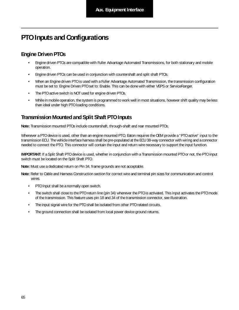
65
Aux. Equipment Interface
PTO Inputs and Configurations
Engine Driven PTOs• Engine driven PTOs are compatible with Fuller Advantage Automated Transmissions, for both stationary and mobile
operation.
• Engine driven PTOs can be used in conjunction with countershaft and split shaft PTOs.
• When an Engine driven PTO is used with a Fuller Advantage Automated Transmission, the transmission configuration must be set to: Engine Driven PTO set to: Enable. This can be done with either VEPS or ServiceRanger.
• The PTO active switch is NOT used for engine driven PTOs.
• While in mobile operation, the system is programmed to work well in most situations, however shift quality may be less than ideal under high PTO loading conditions.
Transmission Mounted and Split Shaft PTO InputsNote: Transmission mounted PTOs include countershaft, through-shaft and rear mounted PTOs.
Whenever a PTO device is used, other than an engine mounted PTO, Eaton requires the OEM provide a “PTO active” input to the transmission ECU. The vehicle interface harness shall be pre-populated at the ECU 38-way connector with wiring and a connector needed to connect the PTO. This connector will contain the input and return wire necessary to support the input function.
IMPORTANT: If a Split Shaft PTO device is used, whether in conjunction with a Transmission mounted PTO or not, the PTO input switch must be located on the Split Shaft PTO.
Note: Must use a dedicated return on Pin 34, frame grounds are not acceptable.
Note: Refer to Cable and Harness Construction section for correct wire and terminal pin sizes for communication and control wires.
• PTO input shall be a normally open switch.
• The switch shall close to the PTO return line (pin 34) whenever the PTO is activated. This input activates the PTO mode of the transmission. This feature uses pin 18 and 34 of the transmission connector, see illustration.
• The input signal wire for the PTO shall be isolated from other PTO related circuits.
• The ground connection shall be isolated from local power device ground returns.
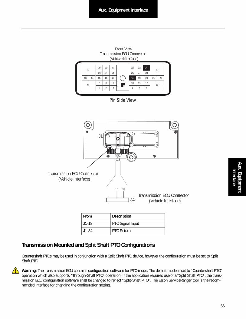
66
Aux. Equipment InterfaceAux. Equipm
ent Interface
Transmission Mounted and Split Shaft PTO Configurations
Countershaft PTOs may be used in conjunction with a Split Shaft PTO device, however the configuration must be set to Split Shaft PTO.
Warning: The transmission ECU contains configuration software for PTO mode. The default mode is set to “Countershaft PTO” operation which also supports “Through-Shaft PTO” operation. If the application requires use of a “Split Shaft PTO”, the trans-mission ECU configuration software shall be changed to reflect “Split-Shaft PTO”. The Eaton ServiceRanger tool is the recom-mended interface for changing the configuration setting.
From Description
J1-18 PTO Signal Input
J1-34 PTO Return
24
29 30
15 16
26
20
3432 33
19
7
3
8 9
1 2 6
11 12
4 5
2221
38
36
37
13 14
3510
17
23
Front ViewTransmission ECU Connector
(Vehicle Interface)
31
25 2827
18
Pin Side View
34
J1
18
Transmission ECU Connector (Vehicle Interface)
Transmission ECU Connector (Vehicle Interface)
34
J4
!
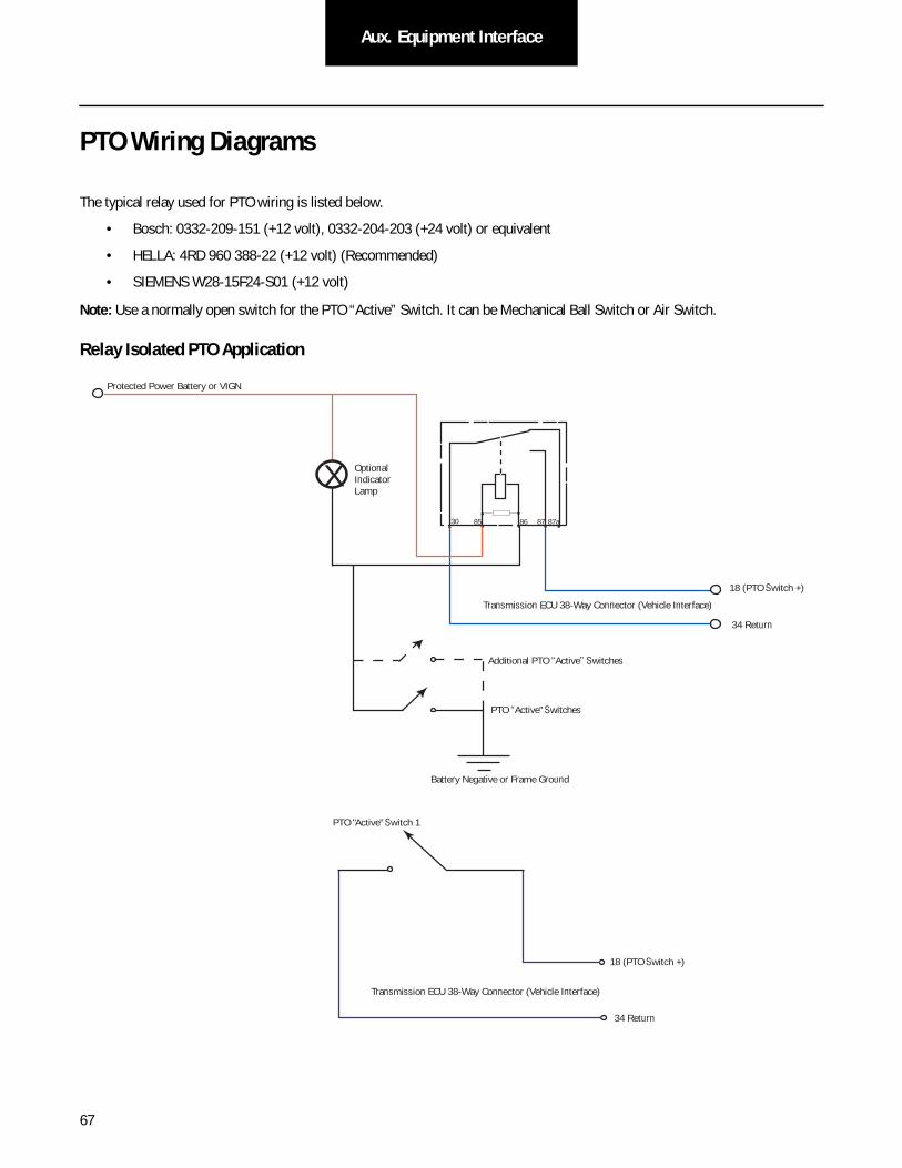
67
Aux. Equipment Interface
PTO Wiring Diagrams
The typical relay used for PTO wiring is listed below.
• Bosch: 0332-209-151 (+12 volt), 0332-204-203 (+24 volt) or equivalent
• HELLA: 4RD 960 388-22 (+12 volt) (Recommended)
• SIEMENS W28-15F24-S01 (+12 volt)
Note: Use a normally open switch for the PTO “Active” Switch. It can be Mechanical Ball Switch or Air Switch.
Relay Isolated PTO Application
30 85 86 87 87a
X
Protected Power Battery or VIGN
OptionalIndicator Lamp
Transmission ECU 38-Way Connector (Vehicle Interface)
PTO “Active" Switches
Battery Negative or Frame Ground
18 (PTO Switch +)
34 Return
Additional PTO “Active” Switches
Transmission ECU 38-Way Connector (Vehicle Interface)
PTO "Active" Switch 1
18 (PTO Switch +)
34 Return
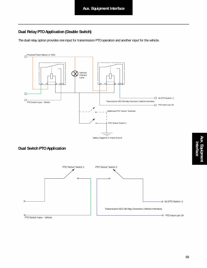
68
Aux. Equipment InterfaceAux. Equipm
ent Interface
Dual Relay PTO Application (Double Switch)
The dual relay option provides one input for transmission PTO operation and another input for the vehicle.
Dual Switch PTO Application
30 85 86 87 87a30 85 86 87 87a
X
Protected Power Battery or VIGN
OptionalIndicator Lamp
PTO Switch Input - Vehicle
PTO "Active" Switch 1
Transmission ECU 38-Way Connector (Vehicle Interface)
18 (PTO Switch +)
PTO return pin 34
Battery Negative or Frame Ground
Additional PTO “Active” Switches
PTO Switch Input - Vehicle
Transmission ECU 38-Way Connector (Vehicle Interface)
PTO "Active" Switch 2PTO "Active" Switch 1
18 (PTO Switch +)
PTO return pin 34

69
Line Inspection and End of Line
Line Inspection and Road Test Instructions
The checklist was developed as an installation tool for line personnel to ensure the correct operation of each vehicle and to assist the vehicle OEM to identify transmission quality related issues as well as OEM line quality issues. Used correctly, this checklist identifies transmission issues and aids in tracking the problem until corrected.
The recommended use of the checklist is as follows:
1. A separate checklist should be filled out for each vehicle built with Eaton Fuller transmissions. If these checks and infor-mation can be combined with an existing form, the Line Inspection form does not need to be used.
2. The section identified as PRE-START CHECKS should be performed prior to the initial start-up of the vehicle. This sec-tion ensures the transmission has the correct power supplies, sufficient lubricant, and correct transmission shift tables.
3. Perform any necessary corrective action prior to the dyno or road testing.
4. The DYNO/ROAD TEST section is used to verify that all transmission systems are functional and the Drivers Manual and Shift Label are supplied in the cab.
5. With a record of transmission related information and repairs made to each unit, the OEM is able to track and correct repeated quality issues.
6. A copy of the checklist should be recorded for installation history. OEM line personnel should become familiar with the checklist for the transmission prior to a scheduled build. Eaton OEM Engineering Support Group can coordinate training and information to expedite this process.
This checklist represents a generic system which can be tailored to the individual OEM to achieve the best possible method of transmission installation verification. Eaton recommends the use of this system to maintain the utmost in satisfactory operation and long service life.
Each transmission system installed at the OEM shall pass the line checklist requirements per the Eaton Line Inspection Form prior to shipment from the OEM plant.

70
Line Inspection and End of LineLine Inspection and End of Line
Line Inspection
This transmission is equipped with a neutral interlock system that when properly installed prevents the engine from cranking with the transmission in-gear.
Warning: Failure to perform installation pre-start checks may result in the engine cranking immediately when ignition is moved to the “START” position or to the “ON” position.
Warning: To prevent undesired vehicle movement for new installations, always set the parking brake prior to turning the ignition key “ON” and also prior to attempting “START”.
Warning: Improper installation of the OEM Start Enable Circuit could result in enabling the vehicle to be started in gear.
Pre-Start Inspection and Initial Starting Requirements
Pre-Start Inspection
• Verify the transmission has been filled with the correct amount and type of lubricant before starting the engine. Failure to add sufficient lubricant could damage the transmission. See Lubricant Requirement section in this manual for details.
The transmission is equipped standard with an oil level sight glass. When the transmission oil level is at or above 3/4 the sight glass then it is at or above the minimum oil fill level.
To check the oil level with the sight glass:
• Vehicle engine shall be stopped and parked on level ground.
• Wipe dirt from the oil level sight glass.
• When the transmission oil level is at or above 3/4 the sight glass then it is at or above the minimum oil fill level.
!
!
!
1 2
71
Line Inspection and End of Line
Before Cranking Engine
• Verify Neutral is selected on the shift input device.
• Turn the ignition key to the “On” position and visually observe the power up procedure.
Warning: During the initial power up of this transmission, the gear display will show an alternating “N” and “F”. This is a normal occurrence on all Fuller Advantage Automated Transmissions. This condition will persist until the initial clutch adjustment and grade sensor calibrations are completed. See following procedures.
• The alternating “N” indicates the transmission has verified neutral.
• The alternating “F” is an indication of an active fault code.
• It is normal for this system to detect an active fault code 27 (clutch adjustment fault) and active fault code 68 (grade sensor calibration fault) during initial power up.
• If the system detects active faults other than 27 and 68, refer to the diagnostic procedure in this manual.
Warning: Once the engine has been started, the transmission automatically initiates a clutch adjustment procedure.
• During the clutch adjustment procedure, the operator will be unable to select an active operating mode for the transmission. The shift input device will be locked out from operator request.
• The clutch adjustment procedure could take up to 35 seconds to complete.
• The clutch adjustment procedure will continue even if the engine is shut off.
Note: Once the clutch adjustment is complete, Eaton requires the grade sensor be calibrated prior to dyno. Refer to the following procedure.
Warning: Failure to calibrate the grade sensor prior to dyno may lead to unsatisfactory shift performance. This condition could be misinterpreted as a product defect and could lead the operator to unnecessary repair.
!
!
!

72
Line Inspection and End of LineLine Inspection and End of Line
Grade Sensor Calibration
Process Requirements:
• Vehicle must be on level ground before initiating the grade sensor calibration.
• Ground surface must be within +/-0.5% grade (.28 deg) level.
Warning: Failure to adhere to ground surface conditions may lead to unsatisfactory shift performance. This condition could be misinterpreted as a product defect and could lead the operator to unnecessary repair.
• Verify the suspension is fully aired.
• Verify the suspension is set to proper ride height.
• Engine shall not be running during the grade sensor calibration.
There are three options for completing the grade sensor calibration. The process for each option is listed below. Your OEM may implement any of these processes.
Grade Sensor Calibration Tool
1. Key On
2. Engine shall not be running
3. Plug grade sensor calibration tool into 9-pin diagnostic connector
4. Push the button on top of tool
5. Observe the pass/fail indicator on top of tool
• If indicator is green, the calibration was successful.
• If indicator remains red, the calibration failed.
Warning: If the grade sensor fails to calibrate, refer to the diagnostic procedure in this publication.
!
!

73
Line Inspection and End of Line
Shift Input Device Combination
1. Begin with the ignition key off
2. Turn the ignition to the ON position but do not start engine
3. Select “L” on the shift input device. At this point, do not press the brake pedal
4. Press the “Up” arrow once, the gear display should change to 0
5. Press the “Up” arrow five times, the gear display should change to 6
6. Depress the accelerator all the way to the floor and hold until down arrow is shown in the gear display, may take approx-imately 2 seconds
7. Release the accelerator, the gear display should revert back to 0
Note: At this point, the grade sensor offset should be calibrated.
8. Select “N” on the shift input device, the gear display should no longer be flashing an “F”
ServiceRanger (PC-based Diagnostic Tool)
1. Turn ignition switch to On.
2. Plug 9-pin connector into dash port.
3. Click on ServiceRanger icon to launch program.
4. Click on “Go To” and select “Service Routines”.
Note: All available Service Routines will be shown.
5. Click on the “Start” button next to Grade Sensor Calibration.
Note: Read the on screen instructions and ensure that the vehicle meets the requirements for Grade Sensor Calibration.
6. Click on the “Calibrate” button.
7. Wait for the message “Successful: The Grade Sensor Calibration was successful.”
8. Verify that Fault Code 68 FMI 13 has gone inactive.
9. Click on “Disconnect” and close Service Ranger, then disconnect computer from dash port.
Note: If Fault Code 68 is active, see Troubleshooting Guide TRTS0980.
10. Turn ignition switch to Off.
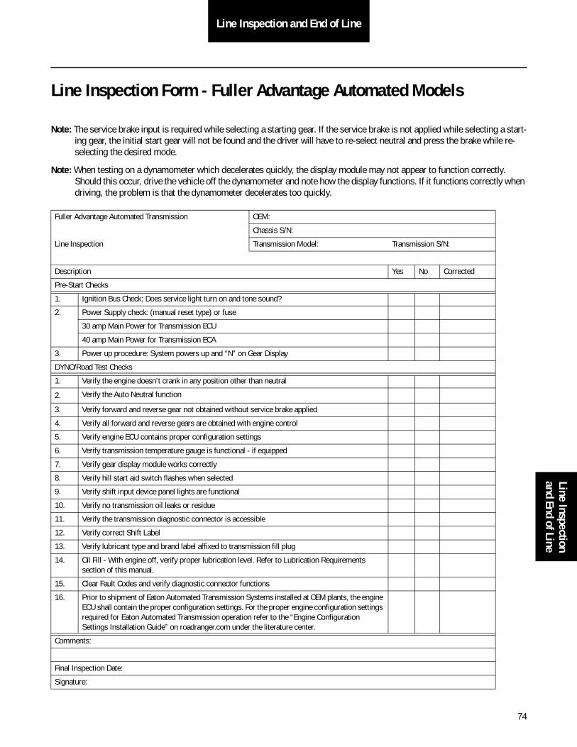
74
Line Inspection and End of LineLine Inspection and End of Line
Line Inspection Form - Fuller Advantage Automated Models
Note: The service brake input is required while selecting a starting gear. If the service brake is not applied while selecting a start-ing gear, the initial start gear will not be found and the driver will have to re-select neutral and press the brake while re-selecting the desired mode.
Note: When testing on a dynamometer which decelerates quickly, the display module may not appear to function correctly. Should this occur, drive the vehicle off the dynamometer and note how the display functions. If it functions correctly when driving, the problem is that the dynamometer decelerates too quickly.
Fuller Advantage Automated Transmission OEM:
Chassis S/N:
Line Inspection Transmission Model: Transmission S/N:
Description Yes No Corrected
Pre-Start Checks
1. Ignition Bus Check: Does service light turn on and tone sound?
2. Power Supply check: (manual reset type) or fuse
30 amp Main Power for Transmission ECU
40 amp Main Power for Transmission ECA
3. Power up procedure: System powers up and “N” on Gear Display
DYNO/Road Test Checks
1. Verify the engine doesn't crank in any position other than neutral
2. Verify the Auto Neutral function
3. Verify forward and reverse gear not obtained without service brake applied
4. Verify all forward and reverse gears are obtained with engine control
5. Verify engine ECU contains proper configuration settings
6. Verify transmission temperature gauge is functional - if equipped
7. Verify gear display module works correctly
8. Verify hill start aid switch flashes when selected
9. Verify shift input device panel lights are functional
10. Verify no transmission oil leaks or residue
11. Verify the transmission diagnostic connector is accessible
12. Verify correct Shift Label
13. Verify lubricant type and brand label affixed to transmission fill plug
14. Oil Fill - With engine off, verify proper lubrication level. Refer to Lubrication Requirements section of this manual.
15. Clear Fault Codes and verify diagnostic connector functions
16. Prior to shipment of Eaton Automated Transmission Systems installed at OEM plants, the engine ECU shall contain the proper configuration settings. For the proper engine configuration settings required for Eaton Automated Transmission operation refer to the “Engine Configuration Settings Installation Guide” on roadranger.com under the literature center.
Comments:
Final Inspection Date:
Signature:

75
Line Inspection and End of Line
Line Inspection Form OEM Wiring Connector/Harness
Note: Eaton requires the checklist items to be incorporated into the OEM control plans.
Note: Eaton requires the above checklist items to be incorporated into the OEM control plans.
Description Yes No Corrected
Deutsch Connector to Transmission ECU 25 +/- 3 lbs. in. [2.82 +/- .33 N•m]
Packard Connector to Push Button Controller 10 +/- 3 lbs. in. [1.1 +/- .33 N•m]
NyoGel 760G lubricant is recommended on connector contacts
No lubricant or foreign material on connector jackscrew
No contaminants on connector contacts
Harness anchor points within 6 in. [15.24 cm] of connectors
No unanchored length of harness greater than 12 in [30.48 cm]
No sharp bends in the harness
Tie wraps on Harness Jacketing only
Harness not anchored to objects that are free to move
All connectors are fully mated and latches locked
All unused connectors or pins should be plugged
No exposed splices or wire strands
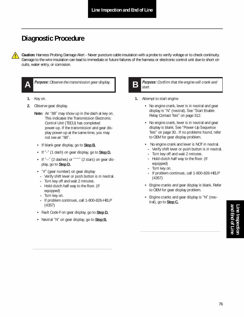
76
Line Inspection and End of LineLine Inspection and End of Line
Diagnostic Procedure
Caution: Harness Probing Damage Alert - Never puncture cable insulation with a probe to verify voltage or to check continuity. Damage to the wire insulation can lead to immediate or future failures of the harness or electronic control unit due to short cir-cuits, water entry, or corrosion.
!
1. Key on.
2. Observe gear display.
Note: An “88” may show up in the dash at key on. This indicates the Transmission Electronic Control Unit (TECU) has completed power-up. If the transmission and gear dis-play power-up at the same time, you may not see an “88”.
• If blank gear display, go to Step B.
• If “-” (1 dash) on gear display, go to Step D.
• If “--” (2 dashes) or “**” (2 stars) on gear dis-play, go to Step D.
• “#” (gear number) on gear display- Verify shift lever or push button is in neutral.- Turn key off and wait 2 minutes.- Hold clutch half way to the floor. (If
equipped)- Turn key on.- If problem continues, call 1-800-826-HELP
(4357)
• Fault Code F on gear display, go to Step D.
• Neutral “N” on gear display, go to Step B.
1. Attempt to start engine
• No engine crank, lever is in neutral and gear display is “N” (neutral). See “Start Enable Relay Contact Test” on page 312.
• No engine crank, lever is in neutral and gear display is blank. See “Power-Up Sequence Test” on page 30.. If no problems found, refer to OEM for gear display problem.
• No engine crank and lever is NOT in neutral. - Verify shift lever or push button is in neutral.- Turn key off and wait 2 minutes.- Hold clutch half way to the floor. (If
equipped)- Turn key on.- If problem continues, call 1-800-826-HELP
(4357)
• Engine cranks and gear display is blank. Refer to OEM for gear display problem.
• Engine cranks and gear display is “N” (neu-tral), go to Step C.
A Purpose: Observe the transmission gear display. B Purpose: Confirm that the engine will crank and start.

77
Line Inspection and End of Line
1. Engage a gear.
Note: AutoShift will not engage a gear from neutral test. UltraShift will not engage a gear from neutral test. UltraShift PLUS Product will not engage a gear from neutral test, or UltraShift AW3 Clutch Engagement test depending on transmission type.
• Unable to engage gear (ie. flashing gear dis-play with down arrows, or solid “N”).
• Solid “#” (gear number) but no drive. See “Front Box Control Test” on page 322. Gear engaged and drives, go to Step E.
1. Check for active fault codes.
Note: If no problem found, refer to OEM for display problem.
• If codes are present, See “Fault Code Isolation Procedure Index” on page 11.
• If no codes and gear display is “-” (1 dash)- Verify shift lever or push button is in neutral.- Turn key off. Wait 2 minutes.- Hold clutch half way to the floor. (If
equipped)- Turn on key.- If problem continues, call 1-800-826-HELP
(4357)
See “Front Box Control Test” on page 322.
• If no codes and gear display is“--” (2 dashes) or “**” (2 stars), See “Power-Up Sequence Test” on page 30.
1. Record and clear inactive fault codes.
2. Drive vehicle and attempt to reset code.
• If no codes are present, test complete.
• If inactive transmission component or Fault Codes, record codes an call 1-800-826-HELP (4357).
• If active transmission component or Fault Codes, See “Fault Code Isolation Procedure Index” on page 11.
C Purpose: Confirm the transmission will engage a gear from neutral. D Purpose: Check for active or inactive fault codes.
E Purpose: Drive vehicle and attempt to duplicate a fault code.
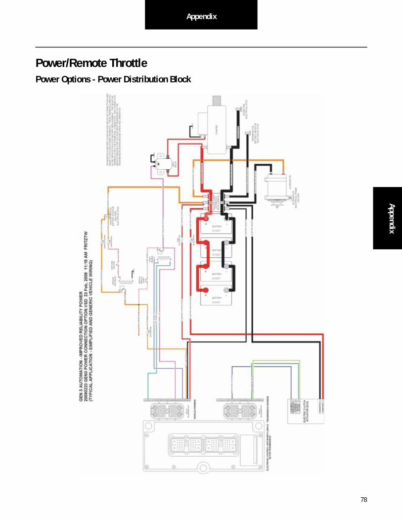
78
AppendixAppendix
Power/Remote ThrottlePower Options - Power Distribution Block
11 2112 4 585637

79
Appendix
Power Options - Single Power Stud
BATTERY + -
12 VOLT
BATTERY + -
12 VOLT
BATTERY + -
12 VOLT
BATTERY + -
12 VOLT
6 1 5
EN
GIN
E C
ON
TR
OL
MO
DU
LE
EN
GIN
E/V
EH
ICLE
_BA
TT
ER
Y_N
EGA
TIV
E
BA
TT
ER
Y N
EGA
TIV
E
ELE
CT
RIC
AL
ST
UD
BA
TT
ER
Y P
OS
ITIV
E
ELE
CT
RIC
AL
ST
UD
M
1 27 3 2 8 4
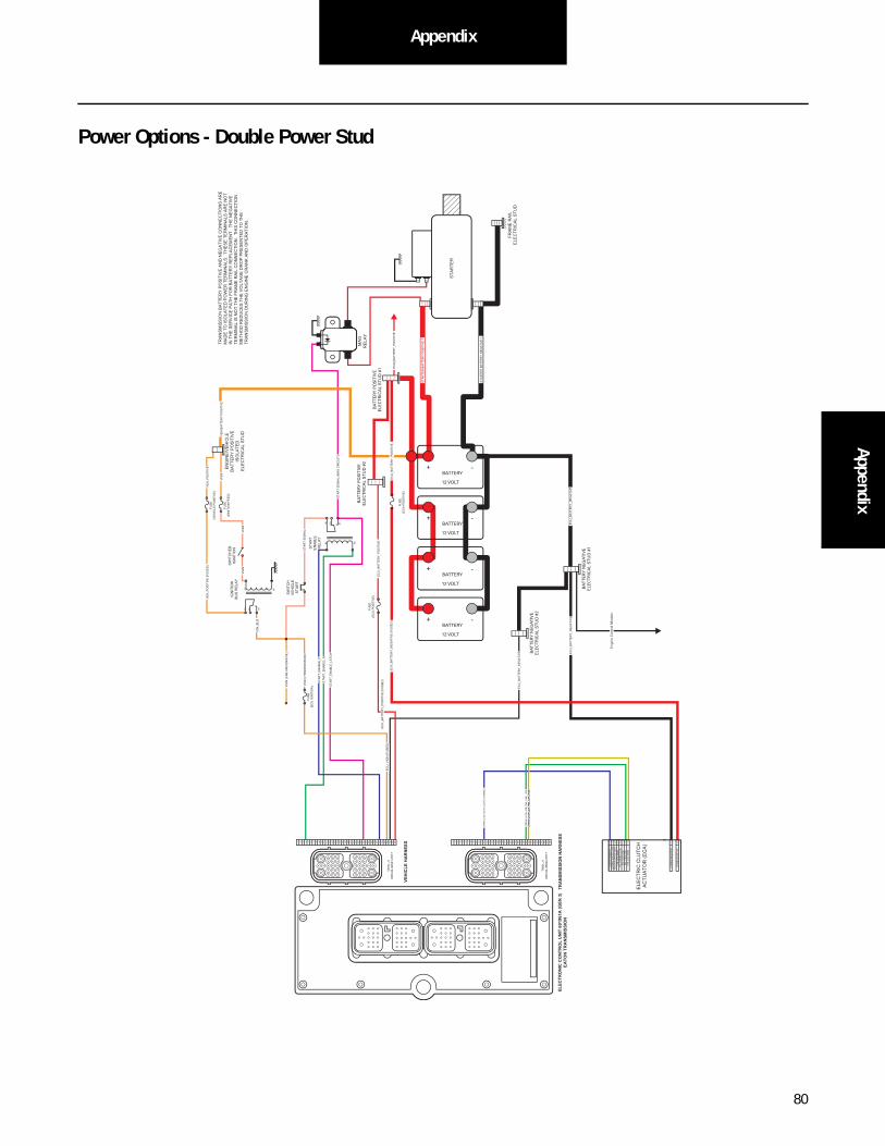
80
AppendixAppendix
Power Options - Double Power Stud
BATTERY + -
12 VOLT
BATTERY + -
12 VOLT
BATTERY + -
12 VOLT
BATTERY + -
12 VOLT
6 1 5 1 27 3 2 8 4
En
gin
e C
on
tro
l Mo
du
le
BA
TT
ER
Y N
EGA
TIV
E
ELE
CT
RIC
AL
ST
UD
#1
BA
TT
ER
Y P
OS
ITIV
E
ELE
CT
RIC
AL
ST
UD
#2
BA
TT
ER
Y P
OS
ITIV
E
ELE
CT
RIC
AL
ST
UD
#1
BA
TT
ER
Y N
EGA
TIV
E
ELE
CT
RIC
AL
ST
UD
#2
M

81
Appendix
Remote Throttle - OEM Requirement
K 1
0 33
2 01
9 10
3 85
86
30
87
REM
OTE
THR
OTT
LE
REM
OTE
TH
RO
TTLE
IN
TER
LOC
K R
ELA
Y ( O
EM S
UPP
LIED
)
VEH
ICLE
1 2 3 4 5 6 7 8 9 10
11
12
13
14
15
16
17
18
19
20
21
22
23
24
25
26
27
28
29
30
31
32
33
34
35
36
37
38
3 5
1 3
3 7 3 8
3 6
2 2
2 6
3 2 3 1
2 5
9
3 4
1 0
OEM
PLU
G -
P 1
DR
C 26
- 38 S
01 - P
017
TRA
NSM
ISSI
ON
1 2 3 4 5 6 7 8 9 10
11
12
13
14
15
16
17
18
19
20
21
22
23
24
25
26
27
28
29
30
31
32
33
34
35
36
37
38
3 5
1 3
3 7 3 8
3 6
2 2
2 6
3 2 3 1
2 5
9
3 4
1 0
TRN
PLU
G - P
2 D
RC
26 - 3
8 S 02
- P 01
7
ELEC
TRO
NIC
CO
NTR
OL
UN
IT ( G
EN 3
) VO
CA
TIO
NA
L / P
ERFO
RM
AN
CE
( 87 )
TH
RO
TTLE
_ CO
MM
ON
_ REM
OTE
( SET
/ RES
UM
E _ C
OM
MO
N )
( 30 )
TH
RO
TTLE
_ CO
MM
ON
_ LO
CA
L ( S
ET / R
ESU
ME _
CO
MM
ON
)
( 85 )
REL
AY _
CO
IL _ R
ETU
RN
( OEM
GR
OU
ND
)

82
AppendixAppendix
Remote Throttle Options - Remote Switch Only
TH
RO
TT
LE H
IGH
(SE
T)
TH
RO
TT
LE L
OW
(RE
SU
ME
)
CO
MM
ON
TH
RO
TT
LE_C
OM
MO
N_R
EM
OT
E (
SE
T/R
ES
UM
E C
OM
MO
N)
TH
RO
TT
LE_H
IGH
_RE
MO
TE
(S
ET
)
TH
RO
TT
LE_H
IGH
(S
ET
)
TH
RO
TT
LE_L
OW
_RE
MO
TE
(R
ES
UM
E)
TH
RO
TT
LE_L
OW
(R
ES
UM
E)
RE
LAY
_CO
IL_R
ET
UR
N
TH
RO
TT
LE_C
OM
MO
N T
HR
OT
TLE
_CO
MM
ON
(E
NG
INE
)
RE
MO
TE
TH
RO
TTLE
CO
NT
RO
L S
WIT
CH
ES
(SE
T/R
ES
UM
E)
TH
RO
TT
LE_L
OW
(R
ES
UM
E)
TH
RO
TT
LE_H
IGH
(S
ET
)
TO
EN
GIN
E T
HR
OT
TLE
(S
ET
/RE
SU
ME
_CO
MM
ON
)
TO E
NG
INE
OR
BO
DY
CO
NT
RO
LLE
R C
RU
ISE
C
ON
TR
OL
INP
UT

83
Appendix
Remote Throttle Options - In Cab Switch with Hard-Wired Remote
TH
RO
TT
LE H
IGH
(SE
T)
TH
RO
TT
LE L
OW
(RE
SU
ME
)
CO
MM
ON
TH
RO
TT
LE_C
OM
MO
N_R
EM
OT
E (
SE
T/R
ES
UM
E_C
OM
MO
N)
TH
RO
TT
LE_C
OM
MO
N_R
EM
OT
E (
SE
T/R
ES
UM
E_C
OM
MO
N)
TH
RO
TT
LE_H
IGH
_RE
MO
TE
(S
ET
)
TH
RO
TT
LE_H
IGH
_CA
B (
SE
T)
TH
RO
TT
LE_H
IGH
(S
ET
)
TH
RO
TT
LE_L
OW
_RE
MO
TE
(R
ES
UM
E)
TH
RO
TT
LE_L
OW
_CA
B (
RE
SU
ME
)
TH
RO
TT
LE_L
OW
(R
ES
UM
E)
RE
LAY
_CO
IL_R
ET
UR
N
TH
RO
TT
LE_C
OM
MO
N (
SE
T/R
ES
UM
E_C
OM
MO
N)
TH
RO
TT
LE_C
OM
MO
N (
EN
GIN
E)
RE
MO
TE
TH
RO
TTLE
CO
NT
RO
L S
WIT
CH
ES
(SE
T/R
ES
UM
E)
TH
RO
TT
LE_L
OW
(R
ES
UM
E)
TH
RO
TT
LE_H
IGH
(S
ET
)
TO
EN
GIN
E T
HR
OT
TLE
(S
ET
/RE
SU
ME
_CO
MM
ON
)
TO E
NG
INE
OR
BO
DY
CO
NT
RO
LLE
R C
RU
ISE
C
ON
TR
OL
INP
UT
TH
RO
TT
LE H
IGH
(SE
T)
TH
RO
TT
LE L
OW
(RE
SU
ME
)
CO
MM
ON
IN-C
AB
TH
RO
TTLE
CO
NT
RO
L S
WIT
CH
ES
(SE
T/R
ES
UM
E)

84
AppendixAppendix
Remote Throttle Options - In Cab Switch with In-line Remote Connector
TH
RO
TT
LE H
IGH
(SE
T)
TH
RO
TT
LE L
OW
(RE
SU
ME
)
CO
MM
ON
TH
RO
TT
LE_C
OM
MO
N_R
EM
OT
E (
SE
T/R
ES
UM
E_C
OM
MO
N)
TH
RO
TT
LE_C
OM
MO
N_C
AB
(S
ET
/RE
SU
ME
_CO
MM
ON
)
TH
RO
TT
LE_H
IGH
_RE
MO
TE
(S
ET
)
TH
RO
TT
LE_H
IGH
_CA
B (
SE
T)
TH
RO
TT
LE_H
IGH
(S
ET
)
TH
RO
TT
LE_L
OW
_RE
MO
TE
(R
ES
UM
E)
TH
RO
TT
LE_L
OW
_CA
B (
RE
SU
ME
)
TH
RO
TT
LE_L
OW
(R
ES
UM
E)
RE
LAY
_CO
IL_R
ET
UR
N
TH
RO
TT
LE_C
OM
MO
N (
SE
T/R
ES
UM
E_C
OM
MO
N)
TH
RO
TT
LE_C
OM
MO
N (
EN
GIN
E)
RE
MO
TE
TH
RO
TTLE
CO
NT
RO
L S
WIT
CH
ES
(SE
T/R
ES
UM
E)
TH
RO
TT
LE_L
OW
(R
ES
UM
E)
TH
RO
TT
LE_H
IGH
(S
ET
)
TO
EN
GIN
E T
HR
OT
TLE
(S
ET
/RE
SU
ME
_CO
MM
ON
)
TO E
NG
INE
OR
BO
DY
CO
NT
RO
LLE
R C
RU
ISE
C
ON
TR
OL
INP
UT
TH
RO
TT
LE H
IGH
(SE
T)
TH
RO
TT
LE L
OW
(RE
SU
ME
)
CO
MM
ON
IN-C
AB
TH
RO
TTLE
CO
NT
RO
L S
WIT
CH
ES
(SE
T/R
ES
UM
E)
DT
06-4
SD
T04
-2P
1 4 3
1 4 3

85
Electrical Requirements
Wiring Diagram - OEM Responsibility
Fuller Advantage™ Automated Transmission with Eaton Shift Lever
ECA
Term
inat
ing
resi
stor
J-19
39/1
1 da
ta li
nk(O
EM s
uppl
ied)
GND
+_
Shie
ldte
rmin
atio
n
Engi
ne E
CM
+ Ba
ttery
For t
rans
mis
sion
di
agno
stic
s pe
rSA
E St
anda
rd Star
ten
able
rela
y
Run
to s
tart
sign
al fr
om
ignt
ion
switc
h
Run
tost
arte
r sol
enoi
d
10 A
MP
only
man
ual r
eset
ting
circ
uit b
reak
er
10 A
MP
fuse
Or
J-15
87 d
ata
link
30 87 86 85
C D B F G A
9-w
ay
30 A
MP
fuse
Batte
ry p
ower
(N
on-s
witc
hed
pow
er)
run
to B
atte
ry
Term
inat
ing
resi
stor
Tran
smis
sion
Con
trolle
r (EC
U)
AF
J
E
GHD
CB
Bulk
head
con
nect
orlo
cate
d at
fire
wal
l
Back
sid
e of
gau
ges
Dash
ligh
ts
Dim
mer
con
trol i
nput
J-19
39 L
ow
J-19
39 H
igh
OEM
Igni
tion
Key
Switc
h Ru
ns to
mai
n po
wer
lead
that
feed
s th
e ig
nitio
n bu
s (O
EM
resp
onsi
ble
for o
verc
urre
nt
prot
ectio
n on
this
line
)
40 A
MP
fuse
Batte
ry p
ower
(N
on-s
witc
hed
pow
er)
run
to B
atte
ry
12
3 4
1
8
2
6
7
5
3 4
1
8
2
6
7
5
Retu
rnAu
to N
eutra
lAu
to N
eutra
l Ret
urn
Rem
ote
Thro
ttle
Term
inat
e PT
O co
ntro
l lin
ein
to c
onne
ctor
for
body
bui
lder
app
licat
ion
38 36 25 31 15 16 17 23 14 35 10 11 26 32 4 18 34 19 33 24 3 2 1
See “Start Enable Relay Requirements” on page 32.

86
Electrical RequirementsElectrical
Requirements
Fuller Advantage™ Automated Transmission with Eaton Push Button
Term
inat
ing
resi
stor
J-19
39/1
1 da
ta li
nk(O
EM s
uppl
ied)
GND
+_
Shie
ldte
rmin
atio
n
Engi
ne E
CM
+ Ba
ttery
For t
rans
mis
sion
di
agno
stic
s pe
rSA
E St
anda
rd Star
ten
able
rela
y
Run
to s
tart
sign
al fr
om
ignt
ion
switc
h
Run
tost
arte
r sol
enoi
d
10 A
MP
only
m
anua
l res
ettin
g ci
rcui
t bre
aker
10 A
MP
fuse
Or
J-15
87 d
ata
link
30 87 86 85
C D B F G A
9-w
ay
30 A
MP
fuse
Batte
ry p
ower
(N
on-s
witc
hed
pow
er)
run
to B
atte
ry
Term
inat
ing
resi
stor
Tran
smis
sion
Con
trolle
r (EC
U)
AF
J
E
GHD
CB
Bulk
head
con
nect
or
loca
ted
at fi
rew
all
Back
sid
e of
gau
ges
Dash
ligh
ts
Dim
mer
con
trol i
nput
J-19
39 L
ow
J-19
39 H
igh
OEM
Igni
tion
Key
Switc
h Ru
ns to
mai
n po
wer
lead
that
feed
s th
e ig
nitio
n bu
s (O
EM
resp
onsi
ble
for o
verc
urre
nt
prot
ectio
n on
this
line
)
40 A
MP
fuse
Batte
ry p
ower
(N
on-s
witc
hed
pow
er)
run
to B
atte
ry
12
ECA
J3 C
1 F
2 F
1
B3
Retu
rn
Auto
Neu
tral
Auto
Neu
tral R
etur
n Re
mot
e Th
rottl
e
Term
inat
e PT
O co
ntro
l lin
e in
to c
onne
ctor
for
body
bui
lder
app
licat
ion
38
36
25
31
27
28
35
10
11
26
32
4 18
34
19
33
24
3 2 1
See “Start Enable Relay Requirements” on page 27.

87
Appendix
Fuller Advantage™ Automated Transmission with Analog Shifter Wiring Diagram
173125
C
B
A
C
B
A
Rangevalve
Splittervalve
Gear selectmotor
Rail selectmotor
Electricshifter
3537
3638
63428
43226
Transmission ECU
OEM
B
C
A
D
For TransmissionDiagnostics
4-way
B - Service Bat. +C - Service Bat. -A - Service Ignition +
BCA 30
29
13 30 29
A B
A B
F GF G
40 AMP fuse
Battery power (Non-switched power)
run to Battery
Engine Flywheel Speed Sensor(Eaton Supplied)
1
C E
C E
3 2
33
1 4 2
W-027 W27-OS_SPEED_MEG
W-029 W29-OS_SPEED_SIG W-028 W28-OS_SPEED_POS
Terminating Resistor
Main shaft speed sensor
Rail select sensor
Gear select sensor
Input shaft speed sensor
181920
101112
78
A
B
C
A
B
C
1516
21 22 Directional output shaft speed sensor
30 AMP fuse
Battery power (Non-switched power)
run to Battery
38 36 25 31 27 28 35 10 11 26 32 4 18 34 19 33 24 3 2 1
Terminatingresistor
2

88
AppendixAppendix
Back side
of gauge dash lights
Dimmer control input
TransmissionECU Connector Pins
J3 C1 F2 F1 B3 J3 C1 F2 F1 B3
25 31 27 28
Terminatingresistor
J1939/11 data link(OEM supplied)
GND+ _
Shieldtermination
Engine ECM
Startenablerelay
Run to startsignal from
igntion switch
Run tostarter solenoid
Return Auto Neutral
Auto Neutral Return Remote Throttle
10 AMP only manual resetting circuit breaker
10 AMPfuse
or
J-1587 data link
30
87
86
85
Bulkhead connectorlocated at firewall
+ Battery
For transmission Diagnostics perSAE Standard
CDBFGA
9-way
AF
J
E
GH
DC
BJ1939 Low
J1939 High
Ignition Key Switch Runs to main power lead thatfeeds the ignition bus (OEM responsible for overcurrent
protection on this line)
Terminate PTO control line into connector for
body builder application
35 10 11 26 32 4 18 34 19 33 24
See “Start Enable Relay Requirements” on page 27.
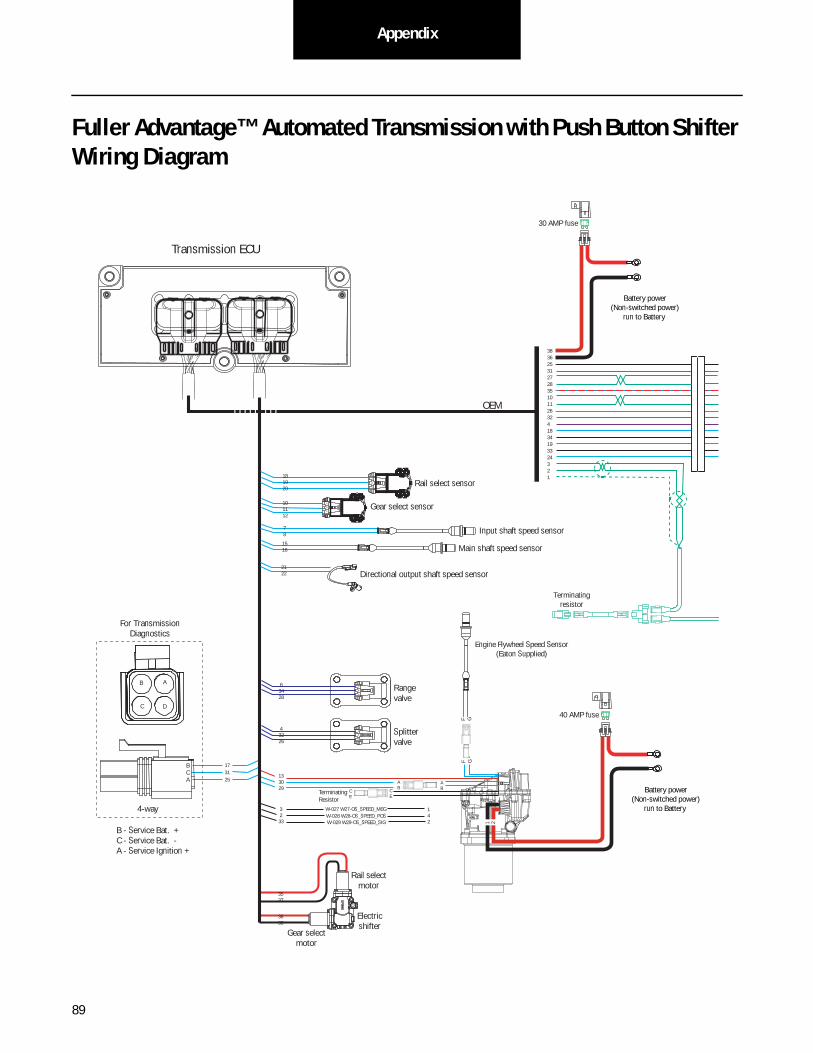
89
Appendix
Fuller Advantage™ Automated Transmission with Push Button Shifter Wiring Diagram
173125
C
B
A
C
B
A
Rangevalve
Splittervalve
Gear selectmotor
Rail selectmotor
Electricshifter
3537
3638
63428
43226
Transmission ECU
OEM
B
C
A
D
For TransmissionDiagnostics
4-way
B - Service Bat. +C - Service Bat. -A - Service Ignition +
BCA 30
29
13 30 29
A B
A B
F GF G
40 AMP fuse
Battery power (Non-switched power)
run to Battery
Engine Flywheel Speed Sensor(Eaton Supplied)
1
C E
C E
3 2 33
1 4 2
W-027 W27-OS_SPEED_MEG
W-029 W29-OS_SPEED_SIG W-028 W28-OS_SPEED_POS
Terminating Resistor
Main shaft speed sensor
Rail select sensor
Gear select sensor
Input shaft speed sensor
181920
101112
78
A
B
C
A
B
C
1516
21 22 Directional output shaft speed sensor
30 AMP fuse
Battery power (Non-switched power)
run to Battery
38 36 25 31 27 28 35 10 11 26 32 4 18 34 19 33 24 3 2 1
Terminatingresistor
2

90
AppendixAppendix
Back side
of gauge dash lights
Dimmer control input
TransmissionECU Connector Pins
J3 C1 F2 F1 B3 J3 C1 F2 F1 B3
25 31 27 28
Terminatingresistor
J1939/11 data link(OEM supplied)
GND+ _
Shieldtermination
Engine ECM
Startenablerelay
Run to startsignal from
igntion switch
Run tostarter solenoid
Return Auto Neutral
Auto Neutral Return Remote Throttle
10 AMP only manual resetting circuit breaker
10 AMPfuse
or
J-1587 data link
30
87
86
85
Bulkhead connectorlocated at firewall
+ Battery
For transmission Diagnostics perSAE Standard
CDBFGA
9-way
AF
J
E
GH
DC
BJ1939 Low
J1939 High
Ignition Key Switch Runs to main power lead thatfeeds the ignition bus (OEM responsible for overcurrent
protection on this line)
Terminate PTO control line into connector for
body builder application
35 10 11 26 32 4 18 34 19 33 24
See “Start Enable Relay Requirements” on page 27.
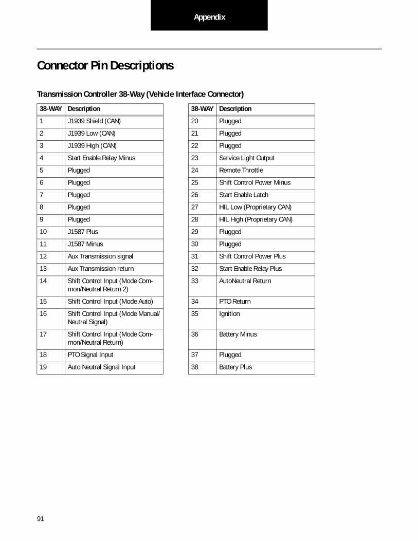
91
Appendix
Connector Pin Descriptions
Transmission Controller 38-Way (Vehicle Interface Connector)
38-WAY Description 38-WAY Description
1 J1939 Shield (CAN) 20 Plugged
2 J1939 Low (CAN) 21 Plugged
3 J1939 High (CAN) 22 Plugged
4 Start Enable Relay Minus 23 Service Light Output
5 Plugged 24 Remote Throttle
6 Plugged 25 Shift Control Power Minus
7 Plugged 26 Start Enable Latch
8 Plugged 27 HIL Low (Proprietary CAN)
9 Plugged 28 HIL High (Proprietary CAN)
10 J1587 Plus 29 Plugged
11 J1587 Minus 30 Plugged
12 Aux Transmission signal 31 Shift Control Power Plus
13 Aux Transmission return 32 Start Enable Relay Plus
14 Shift Control Input (Mode Com-mon/Neutral Return 2)
33 AutoNeutral Return
15 Shift Control Input (Mode Auto) 34 PTO Return
16 Shift Control Input (Mode Manual/Neutral Signal)
35 Ignition
17 Shift Control Input (Mode Com-mon/Neutral Return)
36 Battery Minus
18 PTO Signal Input 37 Plugged
19 Auto Neutral Signal Input 38 Battery Plus
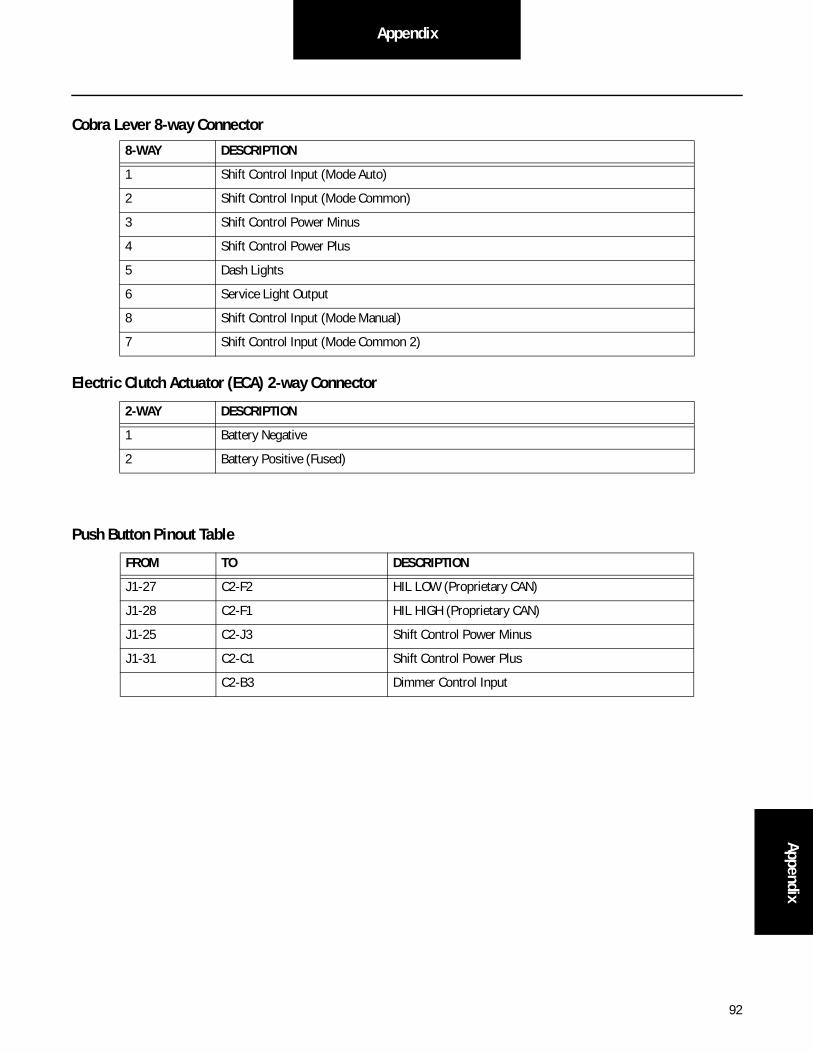
92
AppendixAppendix
Cobra Lever 8-way Connector
Electric Clutch Actuator (ECA) 2-way Connector
Push Button Pinout Table
8-WAY DESCRIPTION
1 Shift Control Input (Mode Auto)
2 Shift Control Input (Mode Common)
3 Shift Control Power Minus
4 Shift Control Power Plus
5 Dash Lights
6 Service Light Output
8 Shift Control Input (Mode Manual)
7 Shift Control Input (Mode Common 2)
2-WAY DESCRIPTION
1 Battery Negative
2 Battery Positive (Fused)
FROM TO DESCRIPTION
J1-27 C2-F2 HIL LOW (Proprietary CAN)
J1-28 C2-F1 HIL HIGH (Proprietary CAN)
J1-25 C2-J3 Shift Control Power Minus
J1-31 C2-C1 Shift Control Power Plus
C2-B3 Dimmer Control Input
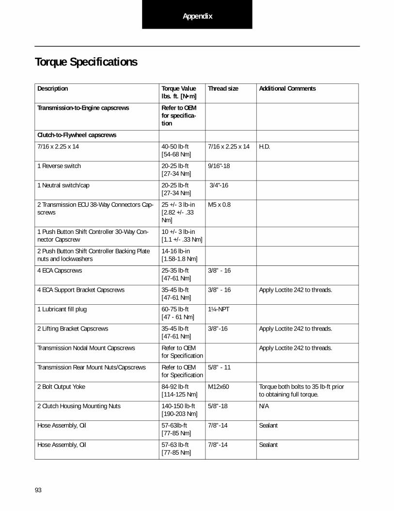
93
Appendix
Torque Specifications
Description Torque Value lbs. ft. [N•m]
Thread size Additional Comments
Transmission-to-Engine capscrews Refer to OEM for specifica-tion
Clutch-to-Flywheel capscrews
7/16 x 2.25 x 14 40-50 lb-ft [54-68 Nm]
7/16 x 2.25 x 14 H.D.
1 Reverse switch 20-25 lb-ft [27-34 Nm]
9/16"-18
1 Neutral switch/cap 20-25 lb-ft [27-34 Nm]
3/4"-16
2 Transmission ECU 38-Way Connectors Cap-screws
25 +/- 3 lb-in [2.82 +/- .33 Nm]
M5 x 0.8
1 Push Button Shift Controller 30-Way Con-nector Capscrew
10 +/- 3 lb-in [1.1 +/- .33 Nm]
2 Push Button Shift Controller Backing Plate nuts and lockwashers
14-16 lb-in [1.58-1.8 Nm]
4 ECA Capscrews 25-35 lb-ft [47-61 Nm]
3/8” - 16
4 ECA Support Bracket Capscrews 35-45 lb-ft [47-61 Nm]
3/8” - 16 Apply Loctite 242 to threads.
1 Lubricant fill plug 60-75 lb-ft [47 - 61 Nm]
1¼-NPT
2 Lifting Bracket Capscrews 35-45 lb-ft [47-61 Nm]
3/8”-16 Apply Loctite 242 to threads.
Transmission Nodal Mount Capscrews Refer to OEM for Specification
Apply Loctite 242 to threads.
Transmission Rear Mount Nuts/Capscrews Refer to OEM for Specification
5/8” - 11
2 Bolt Output Yoke 84-92 lb-ft [114-125 Nm]
M12x60 Torque both bolts to 35 lb-ft priorto obtaining full torque.
2 Clutch Housing Mounting Nuts 140-150 lb-ft [190-203 Nm]
5/8”-18 N/A
Hose Assembly, Oil 57-63lb-ft [77-85 Nm]
7/8”-14 Sealant
Hose Assembly, Oil 57-63 lb-ft [77-85 Nm]
7/8”-14 Sealant
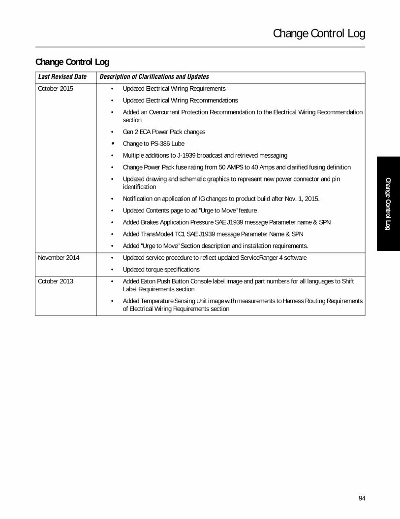
Change Control Log
94
Change Control Log
Change Control LogLast Revised Date Description of Clarifications and Updates
October 2015 • Updated Electrical Wiring Requirements
• Updated Electrical Wiring Recommendations
• Added an Overcurrent Protection Recommendation to the Electrical Wiring Recommendationsection
• Gen 2 ECA Power Pack changes
• Change to PS-386 Lube
• Multiple additions to J-1939 broadcast and retrieved messaging
• Change Power Pack fuse rating from 50 AMPS to 40 Amps and clarified fusing definition
• Updated drawing and schematic graphics to represent new power connector and pin identification
• Notification on application of IG changes to product build after Nov. 1, 2015.
• Updated Contents page to ad "Urge to Move" feature
• Added Brakes Application Pressure SAE J1939 message Parameter name & SPN
• Added TransMode4 TC1 SAE J1939 message Parameter Name & SPN
• Added "Urge to Move" Section description and installation requirements.
November 2014 • Updated service procedure to reflect updated ServiceRanger 4 software
• Updated torque specifications
October 2013 • Added Eaton Push Button Console label image and part numbers for all languages to Shift Label Requirements section
• Added Temperature Sensing Unit image with measurements to Harness Routing Requirementsof Electrical Wiring Requirements section
Copyright Eaton, 2015. Eaton hereby grant their customers, vendors, or distributors permission to freely copy, reproduce and/or distribute this document in printed format. It may be copied only in its entirety without any changes or modifications. THIS INFOR-MATION IS NOT INTENDED FOR SALE OR RESALE, AND THIS NOTICE MUST REMAIN ON ALL COPIES.
Note: Features and specifications listed in this document are subject to change without notice and represent the maxi-mum capabilities of the software and products with all options installed. Although every attempt has been made to ensure the accuracy of information contained within, Eaton makes no repre-sentation about the completeness, cor-rectness or accuracy and assumes no responsibility for any errors or omis-sions. Features and functionality may vary depending on selected options.
For spec’ing or service assistance, call 1-800-826-HELP (4357) or visit www.eaton.com/roadranger.In Mexico, call 001-800-826-4357.
Roadranger: Eaton and trusted partners providing the best products and ser-vices in the industry, ensuring more time on the road.
EatonVehicle GroupP.O. Box 4013Kalamazoo, MI 49003 USA800-826-HELP (4357)www.eaton.com/roadranger
Printed in USA


