arX
iv:1
805.
0703
8v1
[cs
.IT
] 1
8 M
ay 2
018
1
Fundamental Tradeoffs in Communication and
Trajectory Design for UAV-Enabled Wireless
Network
Qingqing Wu, Member, IEEE, Liang Liu, Member, IEEE, and Rui Zhang, Fellow,
IEEE
Abstract
The use of unmanned aerial vehicles (UAVs) as aerial communication platforms is of high practical
value for future wireless systems such as 5G, especially for swift and on-demand deployment in
temporary events and emergency situations. Compared to traditional terrestrial base stations (BSs) in
cellular network, UAV-mounted aerial BSs possess stronger line-of-sight (LoS) links with the ground
users due to their high altitude as well as high and flexible mobility in three-dimensional (3D) space,
which can be exploited to enhance the communication performance. On the other hand, unlike terrestrial
BSs that have reliable power supply, aerial BSs in practice have limited on-board energy, but require
significant propulsion energy to stay airborne and support high mobility. Motivated by the above new
considerations, this article aims to revisit some fundamental tradeoffs in UAV-enabled communication
and trajectory design. Specifically, it is shown that communication throughput, delay, and (propulsion)
energy consumption can be traded off among each other by adopting different UAV trajectory designs,
which sheds new light on their traditional tradeoffs in terrestrial communication. Promising directions
for future research are also discussed.
I. INTRODUCTION
Due to their prominent features of high mobility and flexible deployment, unmanned aerial
vehicles (UAVs), also known as drones, have found many promising usages in the forthcoming
fifth-generation (5G) and future beyond-5G wireless networks, as shown in Fig. 1. Particularly,
UAVs can be used cost-effectively as on-demand aerial platforms to provide or enhance the
The authors are with the Department of Electrical and Computer Engineering, National University of Singapore,
email:{elewuqq, eleliu, elezhang}@nus.edu.sg.
2
Aerial BS Mobile relay Aerial data collector for IoT
Mobile charger for wireless power transfer Aerial mobile user
Aerial helper for traffic
offloading/caching/edge computing
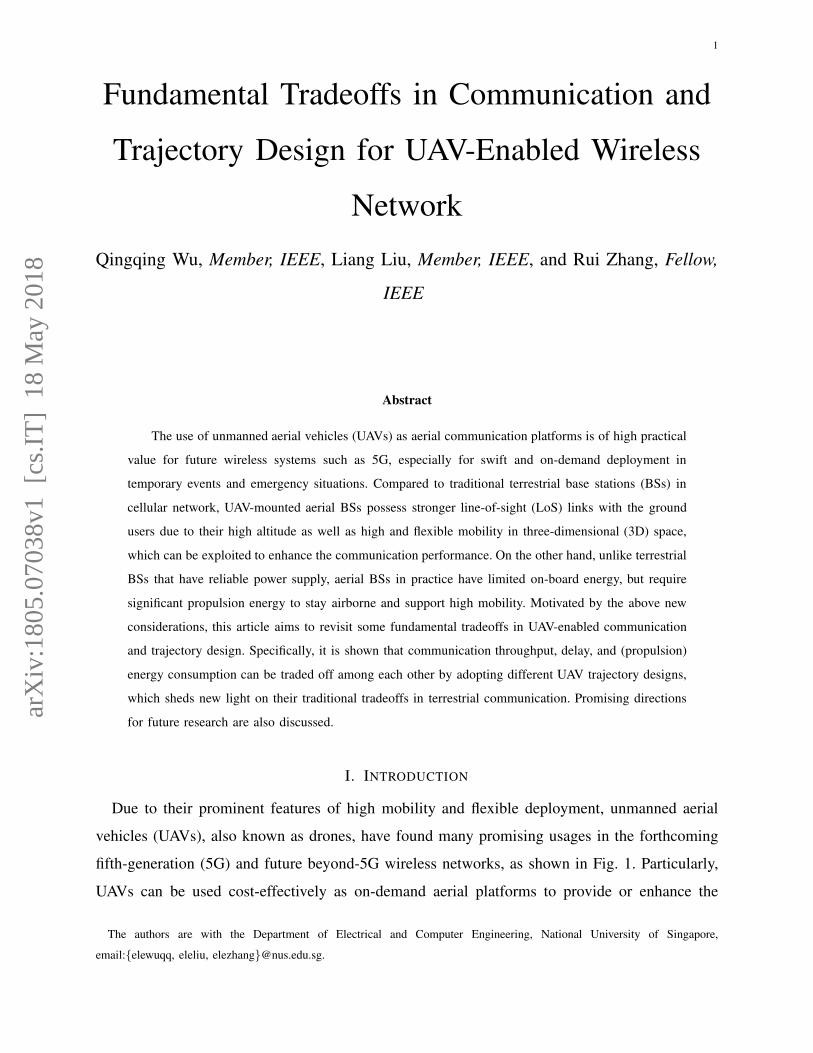
Fig. 1. Typical UAV communication applications in 5G network.
communication services for terrestrial mobiles/devices in a multitude of applications, including
aerial base stations (BSs)/relays in situations without the terrestrial cellular coverage [1]–[3],
aerial helpers for providing new services such as data backhaul/offloading, cached-content mul-
ticasting and edge computing for terrestrial BSs/users, and mobile hubs for energy-efficient data
collection [4] and wireless power transfer [5] for low-power Internet-of-things (IoT) devices
such as sensors and tags. On the other hand, UAVs in many civilian applications such as cargo
delivery and aerial video surveillance may become new aerial users in the cellular network,
which need to have high-performance two-way communications with the ground BSs to receive
control signals and upload payload data in real time [6].
Despite the above promising UAV applications, their future success critically depends on the
development of new and effective UAV-to-ground communication technologies. Compared to
the conventional terrestrial communications, UAV-to-ground communications enjoy the follow-
ing two main advantages that can be exploited for throughput enhancement, namely line-of-
sight (LoS) dominated UAV-to-ground channels and UAV’s controllable high mobility in three-
dimensional (3D) space. On one hand, thanks to the high altitude of UAVs, the probability
of LoS channels between UAVs and the ground users/BSs is in general pretty high, and thus
UAV-to-ground communications are significantly less affected by channel impairments such as
shadowing and fading compared to terrestrial communications. On the other hand, thanks to the
high mobility, swift 3D deployment or even dynamic movement of UAVs becomes feasible so
3
Delay
Thro
ughp
ut
(a) Throughput-delay tradeoff.
Thro
ughp
ut
Energy
(b) Throughput-energy tradeoff.
Dela
y
Energy
(c) Delay-energy tradeoff.
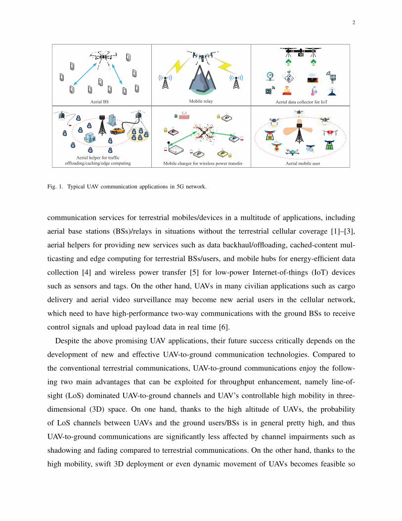
Fig. 2. Three fundamental tradeoffs in UAV-enabled wireless communication.
that they can adjust their locations/trajectories based on the locations and/or movement of the
ground BSs/users to maintain favorable LoS channels. It is worth noting that the LoS channels
enable UAVs to have their signal coverage over a much larger number of ground users or BSs
as compared to the BSs/users in terrestrial communications. Consequently, to achieve optimal
communication and trajectory design, each UAV should not only maintain strong channels to its
served users or connected BSs via flying in proximity of them, but also control its interferences
to other UAVs as well as ground users/BSs so as to maximize the network throughput.
Besides throughput, two important factors also need to be considered in UAV communication
and trajectory deign, namely delay and energy. First, to maximize throughput, each UAV should
communicate with a ground user/BS when its flies sufficiently close to them so as to reduce
their distance and hence improve the link capacity. However, this inevitably incurs more delay
in communication due to the UAV movement. Thus, there is an interesting throughput-delay
tradeoff in UAV-to-ground communications, as shown in Fig. 2 (a). Second, there also exists a
new tradeoff between throughput and energy in UAV-enabled communication as shown in Fig.
2 (b), since the UAV generally needs to consume more propulsion energy to move closer to
the ground users/BSs in order to gain higher throughput. Last, the above two tradeoffs naturally
imply a delay-energy tradeoff as shown in Fig. 2 (c), as delay in UAV-to-ground communication
can be reduced if more propulsion energy is consumed by the UAV to move faster to the ground
users/BSs it is designated to communicate with.
Motivated by the above new and interesting tradeoffs between throughput, delay and (propul-
sion) energy consumption in UAV communication and trajectory design, this article aims to
4
provide an overview on the state-of-the-art results in this new area. In particular, we will focus
on the use of UAVs as communication platforms (e.g., aerial BSs/relays) to serve the terrestrial
users, although such fundamental tradeoffs also exist similarly in the other paradigm with UAVs
as new aerial users to be served by the ground BSs in the cellular network. Next, we discuss the
main differences between these tradeoffs in UAV-enabled communication and their counterparts
in traditional terrestrial communication.
II. FUNDAMENTAL TRADEOFFS IN UAV-ENABLED COMMUNICATION
It is well-known that there exist fundamental tradeoffs between the throughput, delay and
energy in wireless communication [7]. In this section, we first review the classic results on these
tradeoffs in terrestrial communication, and then explain their main differences in UAV-to-ground
communication arising from its unique characteristics as discussed in the preceding section, such
as the LoS channel, the UAV’s trajectory design and its high propulsion energy consumption.
A. Throughput-Delay Tradeoff
The throughput-delay tradeoff has been extensively studied for the terrestrial wireless commu-
nication. For a basic point-to-point wireless communication link, the maximum achievable rate
over fading channels, defined as the ergodic capacity, is achieved by coding over a sufficiently
large number of channel coherence intervals to fully exploit the ergodicity of fading channels
[7]. However, this comes at the cost of long transmission delay that may not be tolerable for
applications with stringent latency requirement. On the other hand, channel coding can be per-
formed over each coherence interval to reduce the delay, resulting in the so-called delay-limited
capacity [7]. However, delay-limited capacity is in general smaller than the ergodic capacity,
and outage is usually inevitable in deep fading. For the general multi-user communication, the
multi-user diversity gain can be attained to improve the network throughput by scheduling the
user with the best channel among all users to communicate in each coherence interval, whereas
this inevitably leads to more significant delay for each user as the number of users increases
[7]. The above results show that there is a general throughput-delay tradeoff for communication
over fading channels. Moreover, it is shown in [8] that there is another tradeoff between the
total throughput of a mobile ad-hoc network (MANET) and the average delay tolerable by the
users in the network due to the random user movement, as each user can wait to communicate
with another user until they become sufficiently close to each other.
5
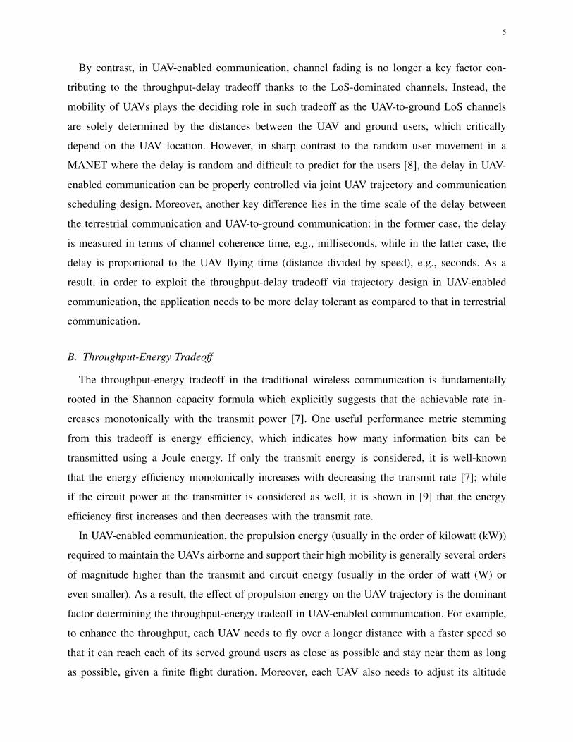
By contrast, in UAV-enabled communication, channel fading is no longer a key factor con-
tributing to the throughput-delay tradeoff thanks to the LoS-dominated channels. Instead, the
mobility of UAVs plays the deciding role in such tradeoff as the UAV-to-ground LoS channels
are solely determined by the distances between the UAV and ground users, which critically
depend on the UAV location. However, in sharp contrast to the random user movement in a
MANET where the delay is random and difficult to predict for the users [8], the delay in UAV-
enabled communication can be properly controlled via joint UAV trajectory and communication
scheduling design. Moreover, another key difference lies in the time scale of the delay between
the terrestrial communication and UAV-to-ground communication: in the former case, the delay
is measured in terms of channel coherence time, e.g., milliseconds, while in the latter case, the
delay is proportional to the UAV flying time (distance divided by speed), e.g., seconds. As a
result, in order to exploit the throughput-delay tradeoff via trajectory design in UAV-enabled
communication, the application needs to be more delay tolerant as compared to that in terrestrial
communication.
B. Throughput-Energy Tradeoff
The throughput-energy tradeoff in the traditional wireless communication is fundamentally
rooted in the Shannon capacity formula which explicitly suggests that the achievable rate in-
creases monotonically with the transmit power [7]. One useful performance metric stemming
from this tradeoff is energy efficiency, which indicates how many information bits can be
transmitted using a Joule energy. If only the transmit energy is considered, it is well-known
that the energy efficiency monotonically increases with decreasing the transmit rate [7]; while
if the circuit power at the transmitter is considered as well, it is shown in [9] that the energy
efficiency first increases and then decreases with the transmit rate.
In UAV-enabled communication, the propulsion energy (usually in the order of kilowatt (kW))
required to maintain the UAVs airborne and support their high mobility is generally several orders
of magnitude higher than the transmit and circuit energy (usually in the order of watt (W) or
even smaller). As a result, the effect of propulsion energy on the UAV trajectory is the dominant
factor determining the throughput-energy tradeoff in UAV-enabled communication. For example,
to enhance the throughput, each UAV needs to fly over a longer distance with a faster speed so
that it can reach each of its served ground users as close as possible and stay near them as long
as possible, given a finite flight duration. Moreover, each UAV also needs to adjust its altitude
6
and/or make sharp turns to avoid blockages in the directions of its served ground users. All these
can lead to more significant propulsion energy consumption for throughput enhancement.
C. Delay-Energy Tradeoff
As discussed in the above two subsections, the throughput-delay and throughput-energy trade-
offs in UAV-enabled communication exhibit interesting new aspects compared to their traditional
counterparts in terrestrial communication. As a result, their corresponding delay-energy tradeoffs
are also drastically different due to the new UAV trajectory design and its high propulsion energy
consumption. For example, to reduce delay, each UAV should fly among its served ground users
with its maximum speed, but remain at its minimum speed (e.g., hovering) when serving them
in its proximity, both resulting in more propulsion energy consumption.
In the rest of this article, we will focus on examining the throughput-delay and throughput-
energy tradeoffs, in the next two sections, respectively. We will provide concrete examples to
illustrate them more clearly, provide overviews on their state-of-the-art results, and also point
out promising directions for future research.
III. THROUGHPUT-DELAY TRADEOFF
In this section, we investigate the joint UAV trajectory and communication design to charac-
terize the throughput-delay tradeoff. Specifically, we first consider a simple setup with one UAV
serving two GUs to draw useful insights. Then, we extend our study to the general case with
multiple UAVs serving multiple users, followed by further discussions on related/future work.
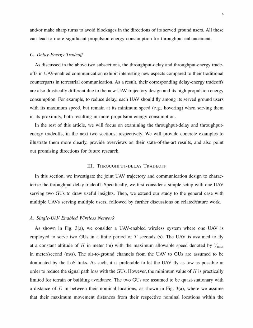
A. Single-UAV Enabled Wireless Network
As shown in Fig. 3(a), we consider a UAV-enabled wireless system where one UAV is
employed to serve two GUs in a finite period of T seconds (s). The UAV is assumed to fly
at a constant altitude of H in meter (m) with the maximum allowable speed denoted by Vmax
in meter/second (m/s). The air-to-ground channels from the UAV to GUs are assumed to be
dominated by the LoS links. As such, it is preferable to let the UAV fly as low as possible in
order to reduce the signal path loss with the GUs. However, the minimum value of H is practically
limited for terrain or building avoidance. The two GUs are assumed to be quasi-stationary with
a distance of D m between their nominal locations, as shown in Fig. 3(a), where we assume
that their maximum movement distances from their respective nominal locations within the
7
, 02
D,0
2
D
Flight duration T
UAV maximum speed Vmax
(a) A UAV-enabled two-user wireless system.
−1000 −800 −600 −400 −200 0 200 400 600 800 1000−20
0
20
x(m), T → 0
y(m
)
−1000 −800 −600 −400 −200 0 200 400 600 800 1000−20
0
20
x(m), T = 40 s
y(m
)
−1000 −800 −600 −400 −200 0 200 400 600 800 1000−20
0
20
x(m), T = 100 s
y(m
)
(b) UAV’s horizontal trajectory for different T .
0 50 100 150 200 250 300
0
0.5
1
Use
r sc
hedu
ling
0 50 100 150 200 250 300
0
0.5
1
Use
r sc
hedu
ling
Time t (s)
GU1GU2
GU1GU2
T = 40 s
T = 100 s
(c) Periodic TDMA of GUs.
0 100 200 300 400 500 600 700 8003
3.5
4
4.5
5
5.5
6
6.5
7
UAV flight period, T (s)
Com
mon
Thr
ough
put (
bps/
Hz)
Upper boundProposed trajectoryStatic UAV
(d) Common throughput versus UAV flight period, T .
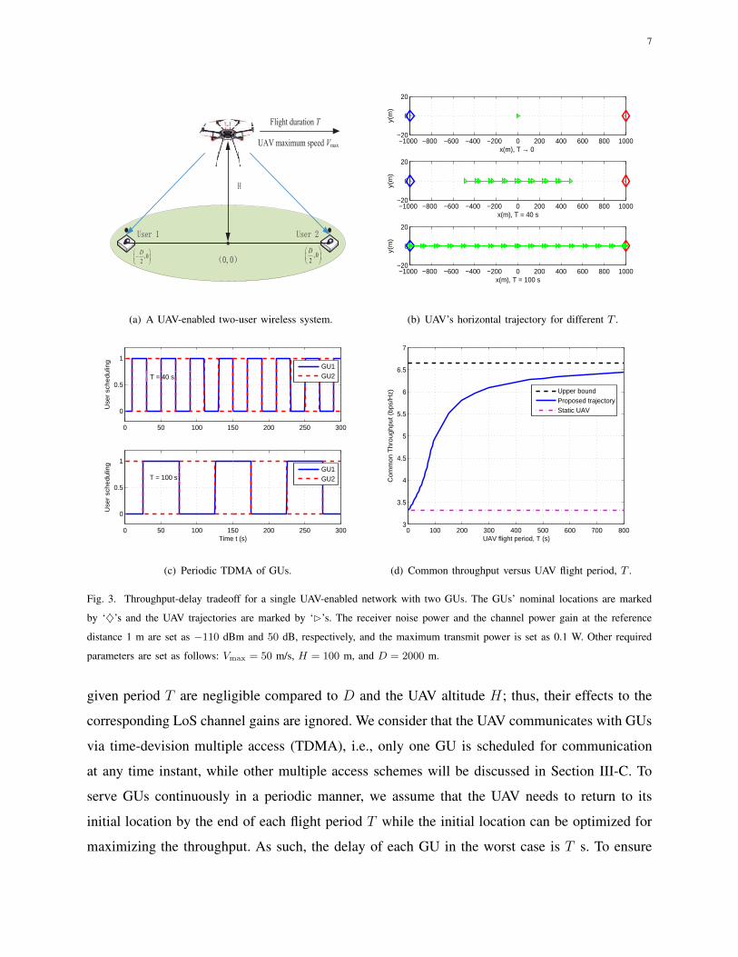
Fig. 3. Throughput-delay tradeoff for a single UAV-enabled network with two GUs. The GUs’ nominal locations are marked
by ‘♦’s and the UAV trajectories are marked by ‘⊲’s. The receiver noise power and the channel power gain at the reference
distance 1 m are set as −110 dBm and 50 dB, respectively, and the maximum transmit power is set as 0.1 W. Other required
parameters are set as follows: Vmax = 50 m/s, H = 100 m, and D = 2000 m.
given period T are negligible compared to D and the UAV altitude H; thus, their effects to the
corresponding LoS channel gains are ignored. We consider that the UAV communicates with GUs
via time-devision multiple access (TDMA), i.e., only one GU is scheduled for communication
at any time instant, while other multiple access schemes will be discussed in Section III-C. To
serve GUs continuously in a periodic manner, we assume that the UAV needs to return to its
initial location by the end of each flight period T while the initial location can be optimized for
maximizing the throughput. As such, the delay of each GU in the worst case is T s. To ensure
8
fairness among GUs, we aim to maximize the common (minimum) throughput between among
the GUs via jointly optimizing the UAV trajectory and communication.
In Fig. 3(b), we show the optimal UAV’s horizontal trajectories projected onto the horizontal
ground plane under different flight periods, T . It can be observed that as T increases, the UAV
tends to fly closer to the two GUs while when T is sufficiently large (e.g., T = 100 s), the UAV
flies between the two GUs with its maximum speed to save more time for hovering right above
the two GUs to maintain the best channel for communication. Furthermore, at any time instant,
to maximize the throughput, the GU that is closer to the UAV (thus with a better channel) should
be scheduled for communication, while the other GU has to wait until the UAV flies closer to
it again. As such, each GU will experience a waiting time of T/2 s for communicating with
the UAV periodically. This is illustrated in Fig. 3(c) where the user scheduling is plotted over
time. It is observed that a larger T leads to a longer waiting time for each GU. Finally, we show
in Fig. 3(d) the achievable common throughput in bits per second per Hertz (bps/Hz) versus
T . Note that the throughput upper bound is obtained by ignoring the time spent on travelling
between the two GUs, which holds when T goes to infinity. In addition, the throughout of a
static UAV is obtained by fixing the UAV at the middle location between the two GUs for all
time. One can observe that compared to the case of a static UAV, the common throughput can
be significantly improved as T increases with a mobile UAV. However, such a throughput gain
is at the cost of scarifying the user delay, which thus reveals a fundamental throughput-delay
tradeoff in UAV-enabled wireless network.
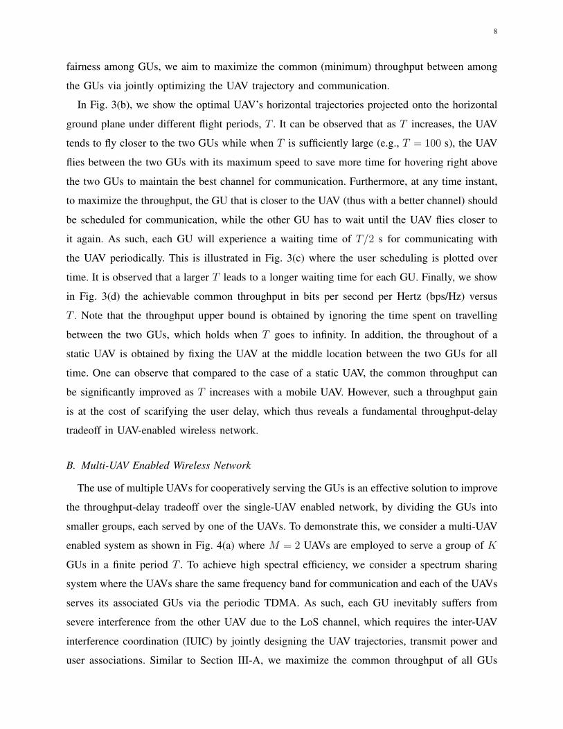
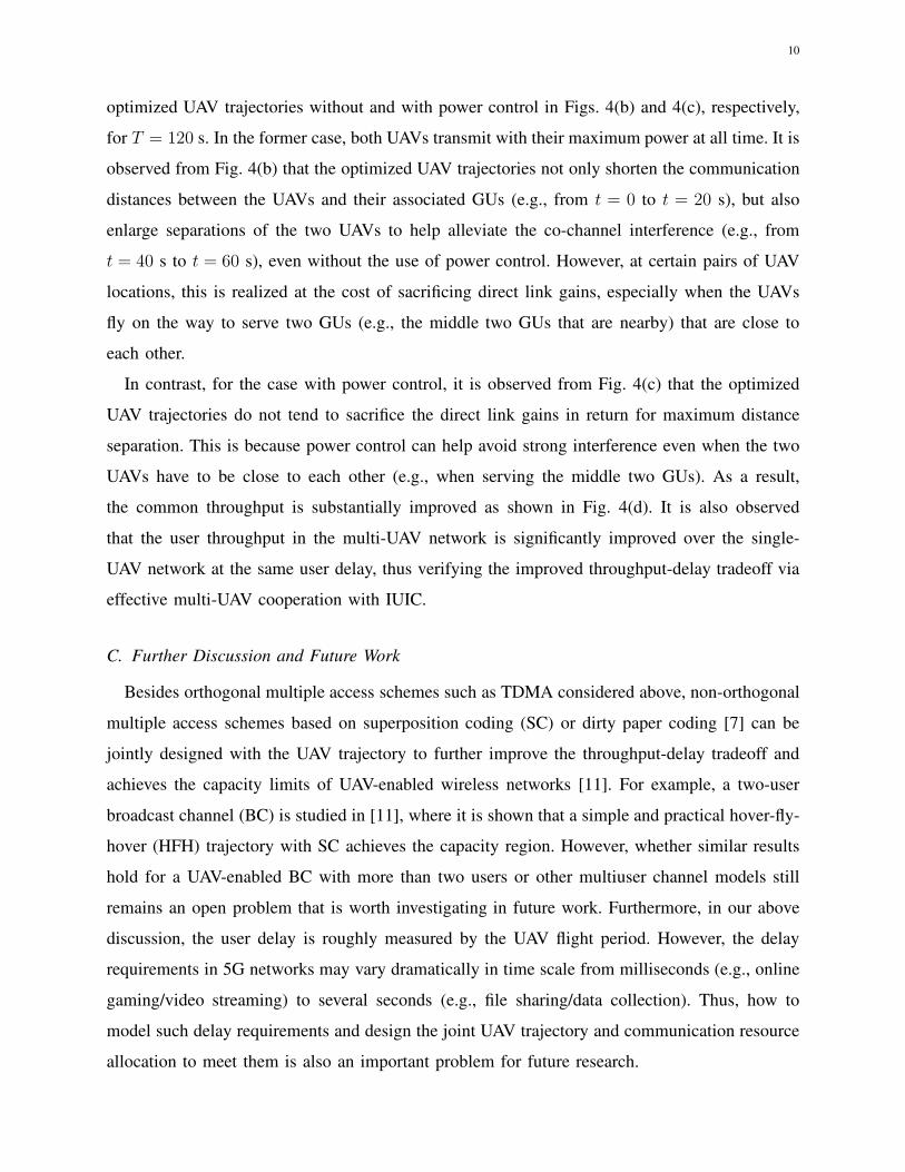
B. Multi-UAV Enabled Wireless Network
The use of multiple UAVs for cooperatively serving the GUs is an effective solution to improve
the throughput-delay tradeoff over the single-UAV enabled network, by dividing the GUs into
smaller groups, each served by one of the UAVs. To demonstrate this, we consider a multi-UAV
enabled system as shown in Fig. 4(a) where M = 2 UAVs are employed to serve a group of K
GUs in a finite period T . To achieve high spectral efficiency, we consider a spectrum sharing
system where the UAVs share the same frequency band for communication and each of the UAVs
serves its associated GUs via the periodic TDMA. As such, each GU inevitably suffers from
severe interference from the other UAV due to the LoS channel, which requires the inter-UAV
interference coordination (IUIC) by jointly designing the UAV trajectories, transmit power and
user associations. Similar to Section III-A, we maximize the common throughput of all GUs
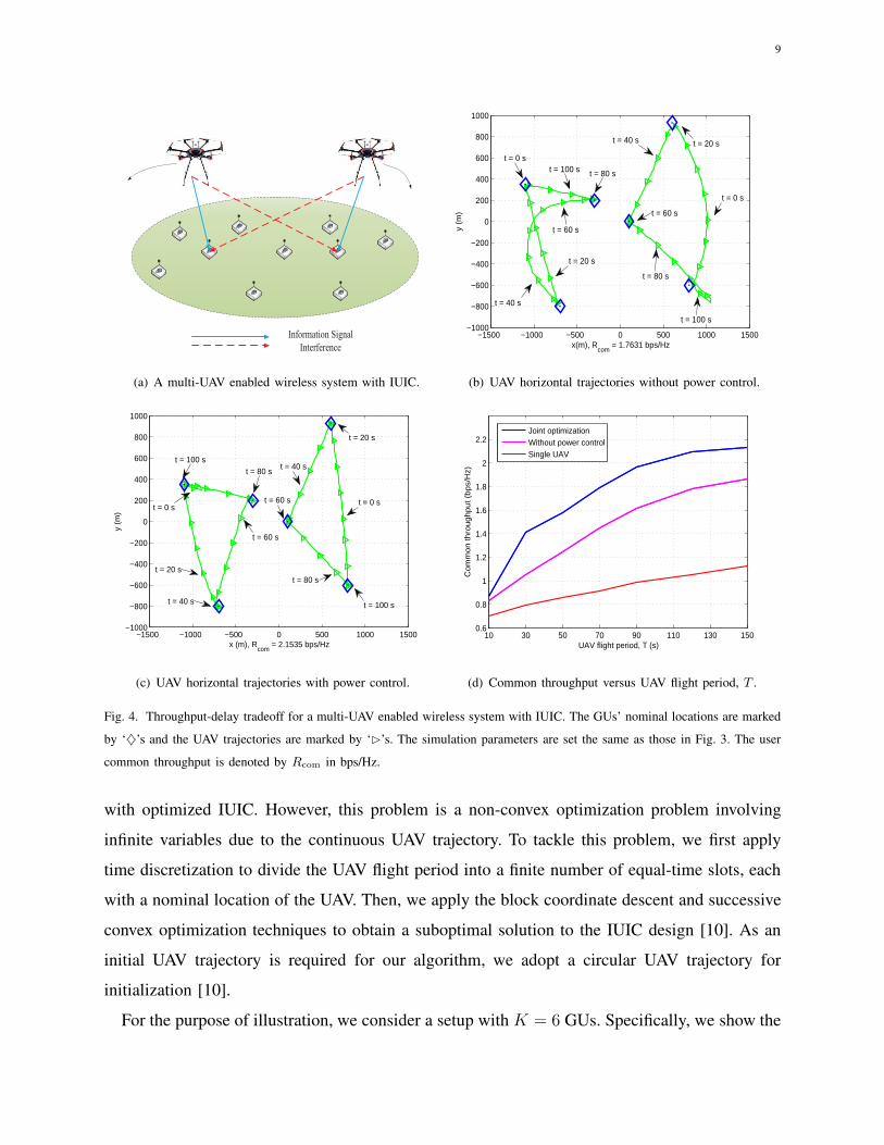
9
Information Signal
Interference
(a) A multi-UAV enabled wireless system with IUIC.
−1500 −1000 −500 0 500 1000 1500−1000
−800
−600
−400
−200
0
200
400
600
800
1000
x(m), Rcom
= 1.7631 bps/Hz
y (m
)
t = 40 s
t = 80 st = 100 s
t = 60 s
t = 20 s
t = 0 s
t = 0 s
t = 20 st = 40 s
t = 60 s
t = 80 s
t = 100 s
(b) UAV horizontal trajectories without power control.
−1500 −1000 −500 0 500 1000 1500−1000
−800
−600
−400
−200
0
200
400
600
800
1000
x (m), Rcom
= 2.1535 bps/Hz
y (m
)
t = 20 s
t = 40 s
t = 100 s
t = 0 s
t = 80 s
t = 0 s
t = 20 s
t = 60 s
t = 40 s
t = 60 s
t = 80 s
t = 100 s
(c) UAV horizontal trajectories with power control.
10 30 50 70 90 110 130 1500.6
0.8
1
1.2
1.4
1.6
1.8
2
2.2
UAV flight period, T (s)
Co
mm
on
th
rou
gh
pu
t (b
ps/
Hz)
Joint optimizationWithout power controlSingle UAV
(d) Common throughput versus UAV flight period, T .
Fig. 4. Throughput-delay tradeoff for a multi-UAV enabled wireless system with IUIC. The GUs’ nominal locations are marked
by ‘♦’s and the UAV trajectories are marked by ‘⊲’s. The simulation parameters are set the same as those in Fig. 3. The user
common throughput is denoted by Rcom in bps/Hz.
with optimized IUIC. However, this problem is a non-convex optimization problem involving
infinite variables due to the continuous UAV trajectory. To tackle this problem, we first apply
time discretization to divide the UAV flight period into a finite number of equal-time slots, each
with a nominal location of the UAV. Then, we apply the block coordinate descent and successive
convex optimization techniques to obtain a suboptimal solution to the IUIC design [10]. As an
initial UAV trajectory is required for our algorithm, we adopt a circular UAV trajectory for
initialization [10].
For the purpose of illustration, we consider a setup with K = 6 GUs. Specifically, we show the
10
optimized UAV trajectories without and with power control in Figs. 4(b) and 4(c), respectively,
for T = 120 s. In the former case, both UAVs transmit with their maximum power at all time. It is
observed from Fig. 4(b) that the optimized UAV trajectories not only shorten the communication
distances between the UAVs and their associated GUs (e.g., from t = 0 to t = 20 s), but also
enlarge separations of the two UAVs to help alleviate the co-channel interference (e.g., from
t = 40 s to t = 60 s), even without the use of power control. However, at certain pairs of UAV
locations, this is realized at the cost of sacrificing direct link gains, especially when the UAVs
fly on the way to serve two GUs (e.g., the middle two GUs that are nearby) that are close to
each other.
In contrast, for the case with power control, it is observed from Fig. 4(c) that the optimized
UAV trajectories do not tend to sacrifice the direct link gains in return for maximum distance
separation. This is because power control can help avoid strong interference even when the two
UAVs have to be close to each other (e.g., when serving the middle two GUs). As a result,
the common throughput is substantially improved as shown in Fig. 4(d). It is also observed
that the user throughput in the multi-UAV network is significantly improved over the single-
UAV network at the same user delay, thus verifying the improved throughput-delay tradeoff via
effective multi-UAV cooperation with IUIC.
C. Further Discussion and Future Work
Besides orthogonal multiple access schemes such as TDMA considered above, non-orthogonal
multiple access schemes based on superposition coding (SC) or dirty paper coding [7] can be
jointly designed with the UAV trajectory to further improve the throughput-delay tradeoff and
achieves the capacity limits of UAV-enabled wireless networks [11]. For example, a two-user
broadcast channel (BC) is studied in [11], where it is shown that a simple and practical hover-fly-
hover (HFH) trajectory with SC achieves the capacity region. However, whether similar results
hold for a UAV-enabled BC with more than two users or other multiuser channel models still
remains an open problem that is worth investigating in future work. Furthermore, in our above
discussion, the user delay is roughly measured by the UAV flight period. However, the delay
requirements in 5G networks may vary dramatically in time scale from milliseconds (e.g., online
gaming/video streaming) to several seconds (e.g., file sharing/data collection). Thus, how to
model such delay requirements and design the joint UAV trajectory and communication resource
allocation to meet them is also an important problem for future research.
11
In practice, the UAV-to-ground LoS channel model is appropriate for rural or sub-urban areas or
when the UAV altitude is sufficiently high. However, for other cases such as in urban environment,
other air-to-ground channel models such as probabilistic LoS model and Rician fading model,
may be more suitable. It is worth noting that such non-LoS channel models may have significant
effects on the optimal UAV trajectory design in UAV-enabled wireless networks. For example,
decreasing the UAV’s flying altitude under the probabilistic LoS model generally decreases the
probability of having LoS links with GUs, while it is always beneficial under the LoS channel
model. As a result, a more complex 3D trajectory optimization problem (as compared to the
2D design in our previous examples under the LoS model) is needed. Moreover, although the
presence of LoS links makes the UAVs well suitable for 5G technologies such as milimeter
wave (mmWave) and massive multiple-input and multiple-output (M-MIMO) communications,
the severe air-to-ground interference issue and 3D mobility-induced Doppler effect deserve for
more investigations in future work.
Last, for the multi-UAV enabled network, we propose the IUIC as an effective technique to
mitigate the strong LoS interference by exploiting the new UAV trajectory design. Alternatively,
motivated by the rapid advance of the wireless backhaul technologies, the UAVs can share
messages and perform cooperative beamforming for more efficient interference mitigation, a
technique so-called coordinate multipoint (CoMP) in the sky [12]. It is worth noting that the
methodology for designing the optimal UAV trajectories for the CoMP case is generally different
from that for the IUIC case. For example, to maximize the cooperative beamforming gain in
CoMP, it may be desirable to let some UAVs form a fleet to serve the GUs along a common
trajectory, while this is apparently undesirable in the IUIC case due to the inter-UAV interference.
Another important issue worthy of further investigation is how to dynamically adjust the UAV
trajectories according to the GUs’ movement to improve their throughput and delay performances
[12].
IV. THROUGHPUT-ENERGY TRADEOFF
In this section, we investigate the joint UAV trajectory and communication deign to character-
ize the throughput-energy tradeoff. Specifically, we first discuss the energy consumption models
for both fixed-wing and rotary-wing UAVs. Then, we revisit the single UAV-enabled system in
Section III-A by taking into account the UAV’s propulsion energy consumption, followed by
further discussions on related/future work.
12
Pow
er c
onsu
mpti
on
Flying speed
(a) Fixed-wing UAV.
Pow
er c
onsu
mpti
on
Flying speed
(b) Rotary-wing UAV.
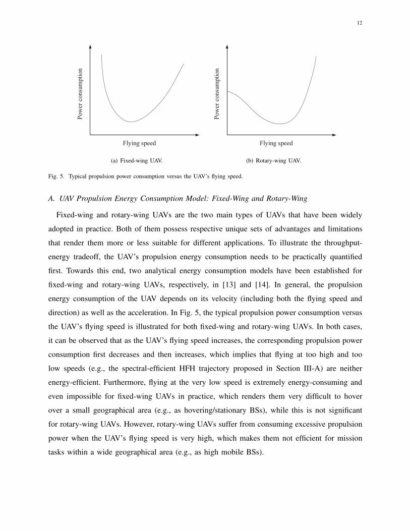
Fig. 5. Typical propulsion power consumption versus the UAV’s flying speed.
A. UAV Propulsion Energy Consumption Model: Fixed-Wing and Rotary-Wing
Fixed-wing and rotary-wing UAVs are the two main types of UAVs that have been widely
adopted in practice. Both of them possess respective unique sets of advantages and limitations
that render them more or less suitable for different applications. To illustrate the throughput-
energy tradeoff, the UAV’s propulsion energy consumption needs to be practically quantified
first. Towards this end, two analytical energy consumption models have been established for
fixed-wing and rotary-wing UAVs, respectively, in [13] and [14]. In general, the propulsion
energy consumption of the UAV depends on its velocity (including both the flying speed and
direction) as well as the acceleration. In Fig. 5, the typical propulsion power consumption versus
the UAV’s flying speed is illustrated for both fixed-wing and rotary-wing UAVs. In both cases,
it can be observed that as the UAV’s flying speed increases, the corresponding propulsion power
consumption first decreases and then increases, which implies that flying at too high and too
low speeds (e.g., the spectral-efficient HFH trajectory proposed in Section III-A) are neither
energy-efficient. Furthermore, flying at the very low speed is extremely energy-consuming and
even impossible for fixed-wing UAVs in practice, which renders them very difficult to hover
over a small geographical area (e.g., as hovering/stationary BSs), while this is not significant
for rotary-wing UAVs. However, rotary-wing UAVs suffer from consuming excessive propulsion
power when the UAV’s flying speed is very high, which makes them not efficient for mission
tasks within a wide geographical area (e.g., as high mobile BSs).
13
B. Energy-constrained Trajectory Optimization
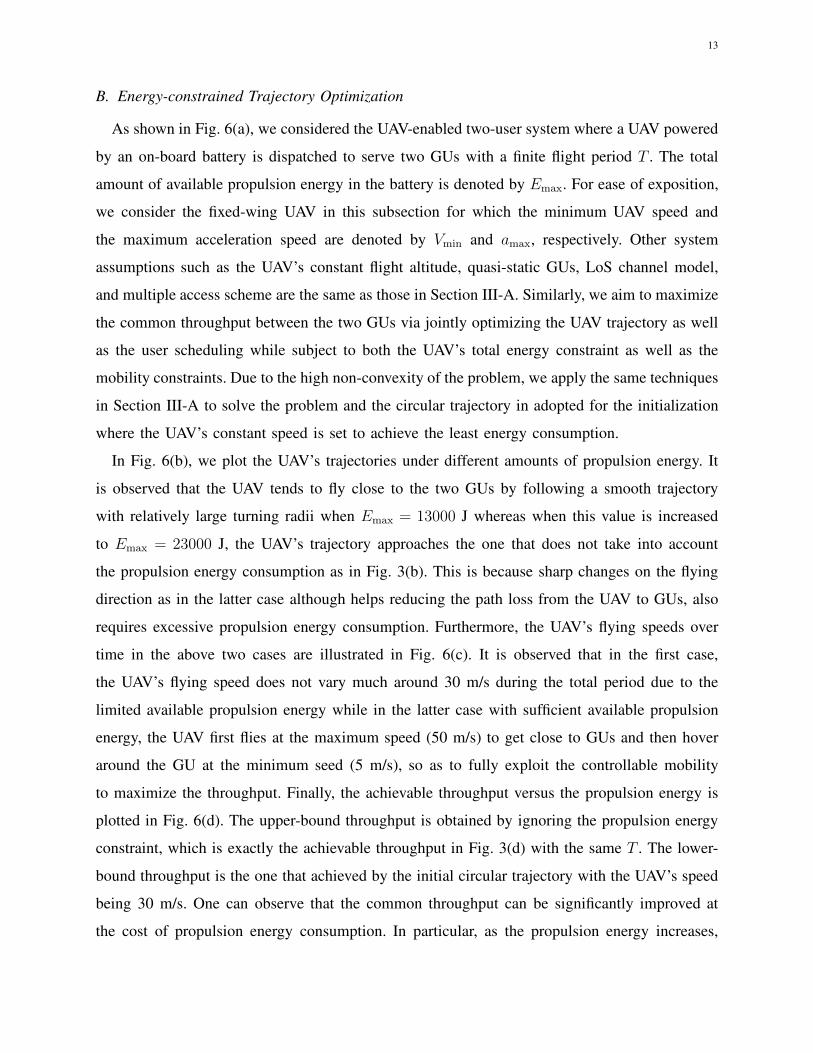
As shown in Fig. 6(a), we considered the UAV-enabled two-user system where a UAV powered
by an on-board battery is dispatched to serve two GUs with a finite flight period T . The total
amount of available propulsion energy in the battery is denoted by Emax. For ease of exposition,
we consider the fixed-wing UAV in this subsection for which the minimum UAV speed and
the maximum acceleration speed are denoted by Vmin and amax, respectively. Other system
assumptions such as the UAV’s constant flight altitude, quasi-static GUs, LoS channel model,
and multiple access scheme are the same as those in Section III-A. Similarly, we aim to maximize
the common throughput between the two GUs via jointly optimizing the UAV trajectory as well
as the user scheduling while subject to both the UAV’s total energy constraint as well as the
mobility constraints. Due to the high non-convexity of the problem, we apply the same techniques
in Section III-A to solve the problem and the circular trajectory in adopted for the initialization
where the UAV’s constant speed is set to achieve the least energy consumption.
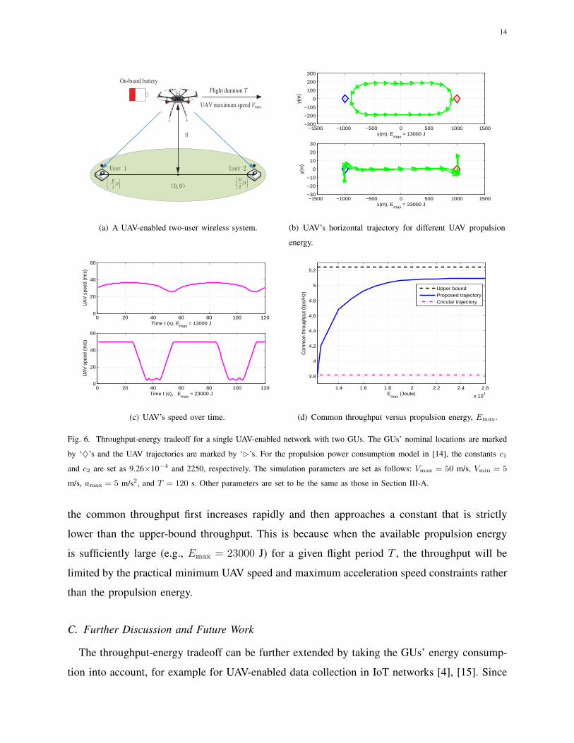
In Fig. 6(b), we plot the UAV’s trajectories under different amounts of propulsion energy. It
is observed that the UAV tends to fly close to the two GUs by following a smooth trajectory
with relatively large turning radii when Emax = 13000 J whereas when this value is increased
to Emax = 23000 J, the UAV’s trajectory approaches the one that does not take into account
the propulsion energy consumption as in Fig. 3(b). This is because sharp changes on the flying
direction as in the latter case although helps reducing the path loss from the UAV to GUs, also
requires excessive propulsion energy consumption. Furthermore, the UAV’s flying speeds over
time in the above two cases are illustrated in Fig. 6(c). It is observed that in the first case,
the UAV’s flying speed does not vary much around 30 m/s during the total period due to the
limited available propulsion energy while in the latter case with sufficient available propulsion
energy, the UAV first flies at the maximum speed (50 m/s) to get close to GUs and then hover
around the GU at the minimum seed (5 m/s), so as to fully exploit the controllable mobility
to maximize the throughput. Finally, the achievable throughput versus the propulsion energy is
plotted in Fig. 6(d). The upper-bound throughput is obtained by ignoring the propulsion energy
constraint, which is exactly the achievable throughput in Fig. 3(d) with the same T . The lower-
bound throughput is the one that achieved by the initial circular trajectory with the UAV’s speed
being 30 m/s. One can observe that the common throughput can be significantly improved at
the cost of propulsion energy consumption. In particular, as the propulsion energy increases,
14
, 02
D,0
2
D
Flight duration T
UAV maximum speed Vmax
On-board battery
(a) A UAV-enabled two-user wireless system.
−1500 −1000 −500 0 500 1000 1500−300
−200
−100
0
100
200
300
y(m
)
x(m), Emax
= 13000 J
−1500 −1000 −500 0 500 1000 1500−30
−20
−10
0
10
20
30
y(m
)
x(m), Emax
= 23000 J
(b) UAV’s horizontal trajectory for different UAV propulsion
energy.
0 20 40 60 80 100 1200
20
40
60
UA
V s
peed
(m/s
)
Time t (s), Emax
= 13000 J
0 20 40 60 80 100 1200
20
40
60
UA
V s
peed
(m/s
)
Time t (s), Emax
= 23000 J
(c) UAV’s speed over time.
1.4 1.6 1.8 2 2.2 2.4 2.6
x 104
3.8
4
4.2
4.4
4.6
4.8
5
5.2
Emax
(Joule)
Com
mon
thro
ughp
ut (b
ps/H
z)
Upper boundProposed trajectoryCircular trajectory
(d) Common throughput versus propulsion energy, Emax.
Fig. 6. Throughput-energy tradeoff for a single UAV-enabled network with two GUs. The GUs’ nominal locations are marked
by ‘♦’s and the UAV trajectories are marked by ‘⊲’s. For the propulsion power consumption model in [14], the constants c1
and c2 are set as 9.26×10⁻⁴ and 2250, respectively. The simulation parameters are set as follows: Vmax = 50 m/s, Vmin = 5
m/s, amax = 5 m/s2, and T = 120 s. Other parameters are set to be the same as those in Section III-A.
the common throughput first increases rapidly and then approaches a constant that is strictly
lower than the upper-bound throughput. This is because when the available propulsion energy
is sufficiently large (e.g., Emax = 23000 J) for a given flight period T , the throughput will be
limited by the practical minimum UAV speed and maximum acceleration speed constraints rather
than the propulsion energy.
C. Further Discussion and Future Work
The throughput-energy tradeoff can be further extended by taking the GUs’ energy consump-
tion into account, for example for UAV-enabled data collection in IoT networks [4], [15]. Since
15
the IoT devices are generally equipped with capacity-limited batteries, how to prolong their life-
time is critical for the sustainability and proliferation of the future IoT ecosystem. Thanks to
the controllable mobility, the UAV-enabled mobile collector can move sufficiently close to the
IoT devices to collect data so as to reduce their transmission energy or the completion time (for
collecting a certain amount of data). In the later case, the energy consumed on circuit operation
can be decreased accordingly, which is also critical for energy-limited IoT devices. However,
the saved energy at the IoT devices is at the cost of the UAV’s movement, which implies an
interesting tradeoff between the IoT devices’ communication energy consumption and the UAV’s
propulsion energy consumption [15].
On the other hand, the UAVs’ energy supply can also be provided by means of other tech-
nologies including solar energy harvesting, laser-beamed wireless power transfer, etc. However,
implementing these technologies generally impose additional design considerations that need to
be further studied. For example, for solar-powered UAVs, while increasing the flying altitude will
lead to higher free space path loss, it helps harvest more solar energy to support more flexible
trajectory design (e.g., higher speed and smaller turning radius) for adapting to GUs’ real-
time movement. As such, a non-trivial tradeoff on optimizing the UAV’s altitude exists, which
could potentially alleviate the throughput-energy tradeoff in practice. Furthermore, in the case
of mission tasks that employ multiple UAVs, besides the inter-UAV coordination on the signal
transmission (e.g., IUIC and CoMP in Section III), novel energy cooperation schemes among the
UAVs are also of great practical significance, which includes sequential energy replenishment,
wireless power transfer, collaborative trajectory design, etc. For example, the propulsion energy
consumption of different UAVs can be balanced via judicious trajectory design so as to maximize
the network life-time.
V. CONCLUSIONS
In this article, we have revisited the fundamental throughput, delay, and energy tradeoffs in
the emerging UAV-enabled wireless communication. In particular, we have shown that the highly
controllable UAV mobility with trajectory design can be jointly designed with the communication
resource allocation so as to balance the throughput and delay requirements of the users as well
as the energy consumption of UAVs. Although this paper focuses on employing UAV as aerial
BSs, the proposed tradeoffs are also applicable to the case of UAV users with considerations
on throughput, delay, and energy consumption. It is worth pointing out that besides the three
16
tradeoffs considered in this paper, there exist other design considerations that are worth pursuing.
For example, although the communication throughput/delay can be further improved/decreased
by employing more UAVs, the cost/deployment efficiency (e.g., the number of UAVs and back-
haul/fronthaul) may be also of great practical interest. Nevertheless, it is hoped that this article
will provide useful insights for the communication and trajectory design of practical UAV-enabled
wireless networks and motivate more work in this forward-looking research field.
REFERENCES
[1] A. Merwaday, A. Tuncer, A. Kumbhar, and I. Guvenc, “Improved throughput coverage in natural disasters: Unmanned
aerial base stations for public-safety communications,” IEEE Veh. Technol. Mag., vol. 11, no. 4, pp. 53–60, Dec. 2016.
[2] Y. Zeng, R. Zhang, and T. J. Lim, “Throughput maximization for UAV-enabled mobile relaying systems,” IEEE Trans.
Commun., vol. 64, no. 12, pp. 4983–4996, Dec. 2016.
[3] J. Chen and D. Gesbert, “Optimal positioning of flying relays for wireless networks: A LOS map approach,” in Proc.
IEEE ICC, 2017, pp. 1–6.
[4] M. Mozaffari, W. Saad, M. Bennis, and M. Debbah, “Mobile unmanned aerial vehicles UAVs for energy-efficient internet
of things communications,” IEEE Trans. Wireless Commun., vol. 16, no. 11, pp. 7574–7589, Nov. 2017.
[5] J. Xu, Y. Zeng, and R. Zhang, “UAV-enabled wireless power transfer: Trajectory design and energy optimization,” IEEE
Trans. Wireless Commun., to appear, [Online] Available at https://arxiv.org/abs/1709.07590.
[6] S. Zhang, Y. Zeng, and R. Zhang, “Cellular-enabled UAV communication: Trajectory optimization under connectivity
constraint,” in Proc. IEEE ICC, 2018, [Online] Available at https://arxiv.org/abs/1710.11619.
[7] D. Tse and P. Viswanath, Fundamentals of Wireless Communication. Cambridge university press, 2005.
[8] M. Grossglauser and D. Tse, “Mobility increases the capacity of ad-hoc wireless networks,” IEEE/ACM Trans. Netw.,
vol. 4, no. 10, pp. 477–486, Aug. 2002.
[9] G. Miao, N. Himayat, and G. Y. Li, “Energy-efficient link adaptation in frequency-selective channels,” IEEE Trans.
Commun., vol. 58, no. 2, pp. 545–554, Feb. 2010.
[10] Q. Wu, Y. Zeng, and R. Zhang, “Joint trajectory and communication design for multi-UAV enabled wireless networks,”
IEEE Trans. Wireless Commun., vol. 17, no. 3, pp. 2109–2121, Mar. 2018.
[11] Q. Wu, J. Xu, and R. Zhang, “Capacity characterization of UAV-enabled two-user broadcast channel,” IEEE J. Sel. Areas
Commun., submitted, [Online] Available at https://arxiv.org/abs/1801.00443.
[12] L. Liu, S. Zhang, and R. Zhang, “CoMP in the sky: UAV placement and movement optimization for multi-user
communications,” IEEE Trans. Wireless Commun., submitted, [Online] Available: https://arxiv.org/abs/1802.10371.
[13] Y. Zeng and R. Zhang, “Energy-efficient UAV communication with trajectory optimization,” IEEE Trans. Wireless Commun.,
vol. 16, no. 6, pp. 3747–3760, Jun. 2017.
[14] Y. Zeng, J. Xu, and R. Zhang, “Energy minimization for wireless communication with rotary-wing UAV,” IEEE Trans.
Wireless Commun., submitted, [Online] Available at https://arxiv.org/abs/1804.02238.
[15] D. Yang, Q. Wu, Y. Zeng, and R. Zhang, “Energy trade-off in ground-to-UAV communication via trajectory design,” IEEE
Trans. Veh. Technol., 2017, to appear, [Online] Available at https://arxiv.org/abs/1709.02975.


