Fusion Welding of Titanium-Tungsten and Titanium-Graphite Composites
Reaction products at the reinforcing
filament-metal matrix interface
are directly related to welding energy input
BY JAM ES R. KENNEDY
ABSTRACT. Fusion welding experiments were conducted on two titanium matrix composite systems: titanium-tungsten wire and titanium-graphite filament. Objectives: Determine the weldability of model composites and observe the influence of weld thermal energy on fiber-matrix reactions.
Results of mechanized and manual gas tungsten-arc (GTA) welding tests indicated that well diffusion-bonded composites generally presented no unusual problems during fusion. The extent of fiber-matrix reactions in both systems was directly proportional to the welding energy input. As energy input increased, tungsten wire dissolution became greater and titanium carbide formation around the graphite filaments grew thicker. Welding energy input thus becomes a significant factor in controlling the nature of fiber-matrix reaction products. Tensile properties of titanium-tungsten composites, both as-diffusion bonded and as-welded, are compared.
Introduction The great potential of composite
materials in providing improved mechanical properties has led to the realization that the extent of their utilization as structural members depends on how easily they may be fabricated and joined into complex shapes.1 5 The possibility of welding metal-matrix composite systems should be an important consideration because of the need to fabricate high
JAMES R. KENNEDY is with the Materials Research Group, Grumman Aerospace Corp., Bethpage, N. Y.
strength, light weight and economical structural joints. However, composite welding remains largely problematical, primarily because the effects of weld thermal energies on fibers and matrix-fiber compatibility for many composites are not yet fully understood.
Welding techniques requiring fusion of the matrix present the most apparent critical condition because the reinforcing fibers will be exposed to a superheated molten matrix and sometimes an intense heat source (e.g. an electron beam or electric arc). This can give rise to accelerated reaction rates between matrix and fiber, possibly leading to extensive interdiffusion, fiber dissolution or complete fiber destruction. Obviously the extent of matrix-fiber interaction depends upon their basic compatibility and the weld thermal history to which they are subjected.
Previous work on composite joining has been generally quite limited, especially in the area of fusion welding. In a study6 to determine joining techniques suitable for boron fiber-aluminum composites it was concluded that gas tungsten-arc, electron beam and plasma fusion welding resulted in severe weld embrittlement and fiber degradation. Conversely, resistance welding of these composites has been relatively successful in producing good quality spot welds with reasonably high strengths.6-8
Interestingly, the molten aluminum matrix of the spot welds had no apparent adverse effects on the tungsten-
cored boron filaments, which was contrary to the effects of higher energy input fusion welds where fiber cracking, break-up and misorientation were common. The effect of poor materials compatibility and high energy input during welding on another type of reinforcing fiber has also been dramatically demonstrated in gas tungsten-arc fusion welds in a sapphire-titanium (single crystal A1 20 3) filament composite.9 The sapphire filament was completely dissolved in the molten titanium during welding, resulting in a coarse, embrittled micro-structure that severely cracked while cooling. Other work where fusion of the matrix resulted in little or no appreciable damage to the reinforcing fibers included resistance welding of steel wire-aluminum10 and fusion welding of tungsten wire-aluminum.9
The only other well known related studies on composite fusion welding have been on dispersion-strengthened materials such as TD-Nickel. The effects of fusion in this case are quite detrimental, causing destruction and agglomeration of the fine thoria dispersion and a drastic lowering of weld joint efficiencies; these problems have led to emphasis on solid state welding techniques.11
An investigation was undertaken to study the effects of fusion welding on two metal-matrix composite systems: titanium-tungsten and titanium-graphite. The titanium-tungsten system is characterized by the absence of compound formation and the formation of a two-phase region. Conversely, the titanium-graphite system is characterized by matrix-fiber reactions that can lead to interfacial compounds.
The objectives of this work were to obtain weldability information on simple model composite systems that would also be generally useful in the development of other composites and to increase understanding of fiber-matrix reactions by observing composites exposed to the dynamic thermal conditions of fusion welding. This paper describes the fabrication and welding of composite specimens, metallographic observations and the .tensile properties of composite-Velds.
Experimental Procedures Materials
Tungsten wire used in this investigation was 0.008 in. commercially pure lamp filament. Typical tensile properties in the as-drawn and cleaned condition were 446 ksi tensile strength and 4.9% elongation. After heat treating at 1600F for 1 hr in vacuum, the tensile strength was 328 ksi with an elongation of 1.9%.
250-s I MAY 19 72
The graphite filaments were uncoated "Courtaulds HM," a high modulus and high strength grade produced from a polyacrilic-nitryal (PAN) precursor. The filaments were about 8 turn (0.0003 in.) in diameter and were spooled as a continuous length in an unwoven yarn. Typical tensile properties were 300 ksi tensile strength and 50 to 60 million psi modulus.
The matrix for both groups of composite specimens was an annealed sheet of commercially pure titanium, Ti75A, in sheet thicknesses up to 0.017 in.
Composite Fabrication
Composite specimens containing the tungsten wire or graphite filaments in the titanium matrix were made by diffusion welding in a vacuum hot press. The titanium-tungsten composites were made by wrapping a continuous length of tungsten wire around a sheet of titanium, which was then sandwiched with additional titanium sheet. The assembly was resistance tack welded at the corners to facilitate further handling. The graphite-titanium composites were prepared by placing a portion of the graphite yarn on a titanium sheet, covering it with another titanium sheet and then tackwelding the sheets together.
Prior to assembly, the titanium was cleaned with an alkaline degrease and water rinse and the tungsten wire was cloth-wiped in isopropyl alcohol.
Graphite was used in the as-received condition.
Before hot pressing, the composite assembly was enveloped in a layer of 0.005 in. thick stainless steel foil to protect against contamination from the hot press graphite rams. The foil was tackwelded around its edges and then its outside surfaces were coated with a thin slurry of 0.05 y.m alumina powder that acted as a parting agent between the foil and the graphite rams. The composite specimens were hot pressed at 1000 psi for 1 hr at 1600F under IO"4 mm Hg vacuum. After hot pressing, the foil layers were removed and the composite specimens were chemically milled to remove a 5 mil surface layer from each side.
The composite specimens in this investigation were prepared and tested with their reinforcing fibers aligned along the axis of loading (i.e., zero degree orientation). Fiber volume percentages of each composite were approximated during composite preparation and later were more accurately determined by metallurgical cross sectioning and counting.
Welding
All fusion welded specimens were prepared by gas tungsten-arc welding. Two types of weld specimens were tested: square groove butt and simple bead-on-sheet. Welds in these experiments were predominantly without filler wire additions. Bead-on-sheet welds were made both transverse and
longitudinal to the fiber direction. Butt welded joints consisted of either machined edges, in which the edges of both the matrix and the fiber ends were coplanar, or of joints in which the matrix edges were removed a few mils by chem milling to provide fiber relief for joint intermeshing. Both top and bottom surfaces of the titanium composites were manually scraped with a draw file in the vicinity of the fusion zone before welding to minimize possible weld contamination.
The fusion welding operation was performed by manual and mechanical techniques, while argon inert gas shielding procedures generally recommended for titanium were used. Typical manual welding parameters for 0.055 in. thick composites were 60 amp, 10 volts and 6 in. per min (ipm) speed. The parameters for mechanized welding on 0.036 in. thick composites were 25 amp, 12 volts and 10 ipm speed.
Testing
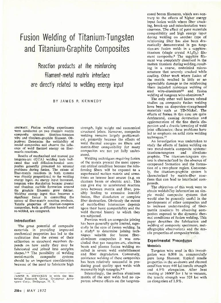
Room temperature tensile tests determined the strength of all matrix and composite specimens. Subsize tensile coupons were used in accordance with ASTM Standards.12 The tensile specimens were generally machined in relation to the fibers, as indicated in Fig. 1. Composite and matrix tests were conducted on an Instron testing machine at a crosshead speed of 0.02 ipm.
Weld Direction
v
/
7 ^
<Z7,
•>
^a
'
" v
Fig. 1—Schematic of composite lay-up and specimen orientation
W E L D I N G R E S E A R C H S U P P L E M E N T I 251-s
Composite Examination
Radiographic inspection was made of the fiber alignment and condition in composite specimens at various stages of the program. Standard metallographic techniques were used to observe and measure the effect of the fibers on matrix microstructure, the extent of fiber-matrix reactions and the overfall influence of welding on the fibers. Characteristics of the fiber-matrix interface and reaction zone were observed and measured with a Reichert P100A metallograph with Knoop microhardness capability and a Norelco-Philips AMR-3 electron microprobe analyzer. All Knoop microhardness tests were made with a 25 g load.
Welded titanium-graphite composites were also examined by X-ray diffraction. A Picker Theta-Theta dif-fractometer employing a copper target for CuKa radiation was used to further identify the reaction product. Fracture surfaces of titanium-tungsten tensile specimens were examined with a Cambridge Stereo Scan Mark II scanning electron microscope.
Results and Discussion Diffusion Bonding
In both composite systems, hot pressing resulted in an advanced stage of matrix diffusion bonding characterized by total migration of the original matrix planar boundaries and nearly complete elimination of prior interfacial voids within the grains.
In the titanium-tungsten composites, consolidation of the matrix was mot complete in regions near the reinforcing filaments. Typically, voids remained adjacent to the tungsten wires along the prior planar boundaries of the matrix. To minimize time and pressure during diffusion bonding and since subsequent welding tests re
vealed no detrimental effects caused by the voids, it was decided to continue using the previously established bonding conditions.
The irregular geometric filament array is a result of the manual winding technique used in the composite layup. Although this random array is not considered optimum for mechanical loading because of obvious nonuniformities, it was employed here because it eliminated the need for more costly, precision layups while it still provided a composite specimen usable within the scope of this preliminary program.
The interfacial region created be-tween the as'-bonded tungsten wire and the titanium matrix consisted of a band of recrystallized, hardened titanium next to a smaller reaction zone (about 4 /xm) immediately adjacent to the tungsten. According to phase diagrams13* 14 for the titanium-tungsten binary system, the interfacial zone should consist of two solid solutions: alpha titanium and tungsten solid solution. These phases form as a result of the beta eutectoid decomposition that occurs at about 715C„ The characteristic lamellar eutectoid structure became more apparent after as-bonded specimens were heat treated for an additional 20 hr at 870C. During heat treatment, the titanium-tungsten reaction zone grew to about 30 ,ixm and displayed a slight, decrease in microhardness, an indication of a tougher transition material.
In the titanium-graphite composites, consolidation of the matrix through the graphite filamentary region did not generally occur. Specimens with low graphite volumes (0.5-1%) were produced in a way that a small center region of filaments was encased with diffusion-bonded titanium that firmly held the filaments
in place. There was also a reaction between the titanium and graphite to form titanium carbide (about 2 /mi) wherever they contacted during diffusion bonding. The presence of TiC was confirmed in both as-diffusion bonded and fusion welded specimens by X-ray diffraction and microhardness measurements. Peak hardness in the carbide region had a Knoop hardness (HK) of about 2700 as compared to reported15 values of 2900. The Ti-TiC phase diagram15 shows only the formation of the TiC phase, which was observed in these specimens.
Attempts to increase graphite volume in other specimens were generally unsatisfactory, resulting in nonuniform and poorly bonded laminates. This difficulty is attributed to the manual layup technique where the handling of a relatively large bundle of unwoven and untaped filaments resulted in thick nonuniform layers. Because of their inconsistencies, such samples proved to be unsatisfactory for subsequent welding and tension tests. Therefore for this work it wasi decided to utilize the low volume graphite specimens exhibiting good matrix bonding only for welding tests where the general microstructural effects of fusion could be observed.
Welding: Titanium-Tungsten Fusion welding was readily accom
plished on the titanium tungsten composites by both manual and mechanized techniques. There was no apparent unusual behavior observed in arc stability, puddling characteristics, or weld bead formation in welding over the tungsten wires. Relatively small increases in welding current (5-10%) were required compared to the matrix-only condition. Manual gas tung-
CO oo ir*
\ % o o
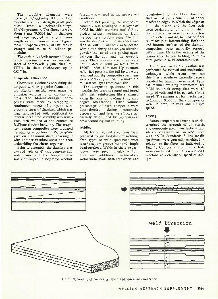
'«. Fig. 2—Transverse sections of titanium-5% tungsten welds. (Top) mechanized GTA, (bottom) manual GTA fusion line indicated by broken lines. Mag: 25X
5
* ' • •
i ...ti
252-s I MAY 1972

sten-arc welding proved to be especially useful in making small energy input corrections on those composite specimens with a nonuniform filament distribution (see Fig. 1).
Typical weld cross sections are shown in Fig. 2. As can be readily observed, matrix consolidation around the tungsten wires was excellent. Further comparison reveals the strong influence of energy input on wire geometry. Manual welding typically caused greater reductions in wire diameters, especially in the upper hot weld region, than did mechanized welding. Wire dissolution in some instances was so severe as to cause nearly complete disappearance of the tungsten. The formation of weld metal voids was, in general, random and infrequent, occurring either along the weld fusion line or near tungsten wires, as shown in Fig. 2. Although porosity formation was not considered serious in these weld tests, a more serious problem could easily develop in composites with high filament volumes (i.e., greater than 2 0 % ) , where outgassing might be difficult and irregular solidification modes could prevail.
A comparison of microstruotures of. manual and mechanized welds is shown in Fig. 3. The effects of overheating are quite obvious in the manual fusion weld: extensive wire dissolution and a highly-cored microstructure of tungsten and alpha titanium solid solution. The mechanized weld condition reveals a matrix microstructure closer to the usually observed acicular alpha transformation product in titanium welds. A cored region does exist immediately around the tungsten wire which has been reduced about 1.5 mils in diameter as a result of welding.
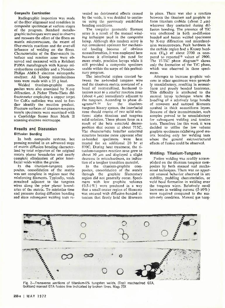
Electron microprobe analyses for both tungsten and titanium distributions were made on various composites, as shown in Fig. 4. The differences in the tungsten gradient from the wire into the matrix for each of the three conditions studied (diffusion bonded, manual weld, mechanized weld) are quite distinct and generally correspond to the micrographic observations. By comparison, the change in the titanium distribution is not so great. It is clear that during diffusion bonding, tungsten appears to be the more mobile species and is readily transported into the matrix; melting of the matrix leads to tungsten dissolution and matrix enrichment. The tungsten gradient appears uniform around each wire and the extent of dissolution is directly related to welding energy input.
Since the effects of weld heating can be quite significant in composites,
consideration must obviously be given to various factors such as fiber strength and dissolution, reaction zone products, matrix alloying and weld metal uniformity. In the titanium-tungsten binary alloy, which forms only solid solutions, appreciable solution hardening can be realized as a result of matrix alloying. Concurrently, the limit of solid solubility of the terminal solid solutions may be rapidly exceeded during weld fusion, leading as seen above to extensive segregation.
As a result of weld thermal energy, the weld metal and heat-affected zone of a composite clearly represents modifications of the original matrix and filament. Whether the particular changes are necessarily detrimental to overall composite performance is not always readily apparent. A certain
percentage of fiber dissolution could perhaps be offset by the fact that a homogeneous, intimate interfacial bond is produced between matrix and fiber and that usable matrix strengthening through solid solution might occur. Clearly, whether or not welding is involved, composite strength (<TC) will be based on the strengths of the various composite constituents, including matrix (o-m), reinforcing filaments (o-f), and reaction products (o-r), such that
Vm<rm + VfCi + V r V / V brr b
where V is the respective volume fraction, and o-r
a and o-rb are two pos
sible reaction zones, such as an interfacial compound and the adjacent diffusion zone. Furthermore, the composite modifications that do occur must be evaluated in terms of the
*
'• -. \ V
i \ ••• l * *
o **~ • , . , • : • . . - 77- •'• V
( . 7. I i % . * » ; . , ; • > Is. • |
'\r.j\A I
Fig. 3—Titanium-tungsten weld microstructures. (Top) mechanized, (bottom) manual Mag: 100X
WELDING RESEARCH SUPPLEMENT | 253-s
* * * • ' \ •
W0&F*"
t W
T i
A s - D i f f u s i o n Bonded
Mechanized GTA
Manual GTA
Fig. 4—Interfacial gradients by electron microprobe analysis. (Top) tungsten into titanium, (bottom) titanium into tungsten. Mag: 1600X
general desirability of producing a welded joint in a given structural component. In comparison, most structural weld design in heat treatable titanium and aluminum alloys is based on the annealed properties of the as-welded condition, with weld metal strength losses compensated for by weld reinforcement.
Welding: Titanium-Graphite When fusion welding was conduct
ed on titanium-graphite specimens that were uniformly diffusion bonded throughout the matrix, the welding behavior was basically the same as in welding titanium without filaments. In specimens with incomplete matrix bonding or highly nonuniform graphite distribution, however, welding
difficulties were encountered. In general, each of the above fabrication defects led to localized overheating during the welding pass, causing "melt-back" in the uppermost matrix sheet, followed by direct exposure of the graphite filaments to the arc. This caused weld sputtering with both erratic arc behavior and "sparking" from incandescent particles of graphite.
A region from a titanium-graphite transverse weld cross section is shown in Fig. 5. Typically, titanium carbide (TiC) is formed around each filament as a result of fusion welding. In turn, the filamentary region is surrounded by a matrix that has a carbide dis-persement of either small stringers or particles. The carbides produced as a result of welding varied in* amount
and form, apparently as a function of energy input and filament concentration. In one case there were three apparent zones: inner (graphite filament and TiC), middle (TiC stringers in titanium matrix), outer (TiC particles in titanium matrix). The inner zone consists of a continuous carbide network formed around the graphite filaments.
In the other condition observed, the filamentary region was characterized by peripheral carbide formations around each filament, with small adjacent carbide particles. It appears that the difference in carbide network between these two cases is related to the interfilament spacing, with closely spaced filaments favoring continuous network formation. The discontinuous
254-s I MAY 19 72
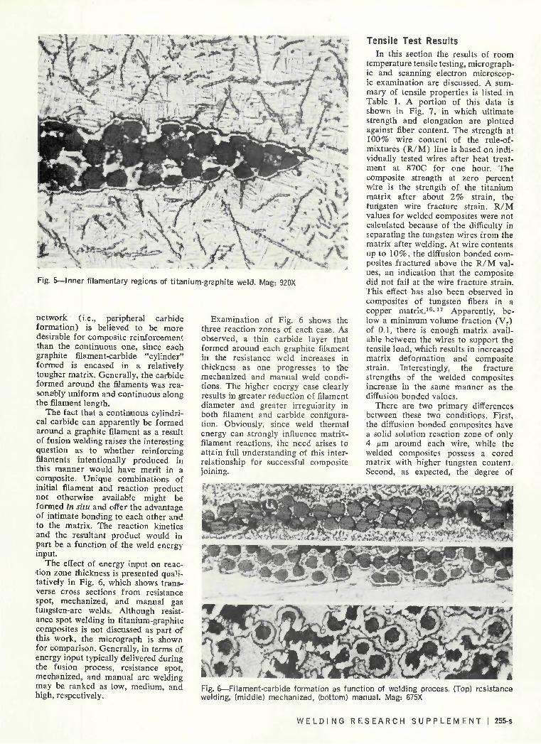
Fig. 5—Inner filamentary regions of titanium-graphite weld. Mag: 920X
network (i.e., peripheral carbide formation) is believed to be more desirable for composite reinforcement than the continuous one, since each graphite filament-carbide "cylinder" formed is encased in a relatively tougher matrix. Generally, the carbide formed around the filaments was reasonably uniform and continuous along the filament length.
The fact that a continuous cylindrical carbide can apparently be formed around a graphite filament as a result of fusion welding raises the interesting question as to whether reinforcing filaments intentionally produced in this manner would have merit in a composite. Unique combinations of initial filament and reaction product not otherwise available might be formed in situ and offer the advantage of intimate bonding to each other and to the matrix. The reaction kinetics and the resultant product would in part be a function of the weld energy input.
The effect of energy input on reaction zone thickness is presented qualitatively in Fig. 6, which shows transverse cross sections from resistance spot, mechanized, and manual gas tungsten-arc welds. Although resistance spot welding in titanium-graphite composites is not discussed as part of this work, the micrograph is shown for comparison. Generally, in terms of energy input typically delivered during the fusion process, resistance spot, mechanized, and manual arc welding may be ranked as low, medium, and high, respectively.
Examination of Fig. 6 shows the three reaction zones of each case. As observed, a thin carbide layer that formed around each graphite filament in the resistance weld increases in thickness as one progresses to the mechanized and manual weld conditions. The higher energy case clearly results in greater reduction of filament diameter and greater irregularity in both filament and carbide configuration. Obviously, since weld thermal energy can strongly influence matrix-filament reactions, the need arises to attain full understanding of this interrelationship for successful composite joining.
sagg 7- am M
Tensile Test Results In this section the results of room
temperature tensile testing, micrographic and scanning electron microscopic examination are discussed. A summary of tensile properties is listed in Table 1. A portion of this data is shown in Fig. 7, in which ultimate strength and elongation are plotted against fiber content. The strength at 100% wire content of the rule-of-mixtures (R /M) line is based on individually tested wires after heat treatment at 870C for one hour. The composite strength at zero percent wire is the strength of the titanium matrix after about 2% strain, the tungsten wire fracture strain. R /M values for welded composites were not calculated because of the difficulty in separating the tungsten wires from the matrix after welding. At wire contents up to 10%, the diffusion bonded composites fractured above the R/M values, an indication that the composite did not fail at the wire fracture strain. This effect has also been observed in composites of tungsten fibers in a copper matrix.16*1T Apparently, below a minimum volume fraction (V f) of 0.1, there is enough matrix available between the wires to support the tensile load, which results in increased matrix deformation and composite strain. Interestingly, the fracture strengths of the welded composites increase in the same manner as the diffusion bonded values.
There are two primary differences between these two conditions. First, the diffusion bonded composites have a solid solution reaction zone of only 4 /urn around each wire, while the welded composites possess a cored matrix with higher tungsten content. Second, as expected, the degree of
: . . ' ' -:
• ••• • : • •• • • • • • •, • • . . . . . , :
Fig. 6—Filament-carbide formation as fu welding, (middle) mechanized, (bottom)
-•** ^ '* *S****lW&BB&§S*3WBm m
nction of welding process. (Top) resistance manual. Mag: 675X
W E L D I N G R E S E A R C H S U P P L E M E N T I 255-s

tungsten wire recrystallization observed in the welded composites appears greater because of their exposure to molten matrix and subse
quent size reduction during welding. It is not clear at this time what the exact effects of higher wire contents would be on composite strength since the
individual effects of wire recrystallization, solid solution formation, and matrix alloying and coring have not been determined. The plateaus in composite
150
i_u oo 1— ^ oo O °° o_ oo « - LU
O h-c_> oo
125
100
s£
o <
O LU
VOL % WIRE Fig. 7—Titanium-tungsten tensile properties
256-s I MAY 19 72
Table—1 Titani
Tungsten Volume Fraction
% 0 0
3.22
4.5 9.8
17.6 0
4.4 0
4.5 5.2 9.9
19.4 100
ium/Tungsten Composite Tensile Data
Specimen Description Annealed sheet, as-received Matrix, as-DB1
As-DB As-DB As-DB As-DB D B + butt weld3
DB + butt weld DB + bead-on-sheet weld4
DB + bead-on-sheet weld DB + bead-on-sheet weld5
DB + bead-on-sheet weld DB + bead-on-sheet weld Tungsten wire, 1600F/1 hr
Number Tested
6 3 3 3 2 2 3 3 2 2 5 2 2 6
Yield Strength6
ksi. 76.7 69.2 90.8 82.4 95.2
103.5 73.0 80.9 82.4
106.8 124.8 105.9 119.8
Ultimate Strength
ksi 93.4 88.7 98.3
102.3 103.5 107.2 92.8
101.5 101.6 129.6 138.7 131.3 132.0 328.0
Elongation7
% 24.3 29.0 18.2 15.8 3.4 1.2
17.5 11.7 14.0 4.5 2.4 4.0 1.7 1.9
Elastic Modulus 106 psi
15.3 14.3 19.7 21.8 21.2 23.7 16.7 17.0 15.5 20.3 18.8 17.2 20.8
i DB = dif fusion bonded; 2 all composites tested at 0 deg or ientat ion; ' no f i l ler—butt welds tested transverse to load axis; 1 no filler—welds longitudinal to load axis; ' mechanized GTA weld—all others manual GTA; ' 0.2% offset; 7 1 in. gage length
ultimate strength exhibited in Fig. 7 may be partially explained by the wire-wire contact within the matrix as shown in Fig. 2. It is known18* 1!l
that this can cause high stress concentrations, thereby decreasing fiber load-carrying ability.
Radiographic and optical examination before and after tensile testing indicated that localized fragmentation of the tungsten wires, away from the final fracture surface, occurred within the homogeneous matrix during tensile loading. In fact, during tensile loading wire fracture was in some cases audible, best described as a sequence of pinging or clicking sounds.
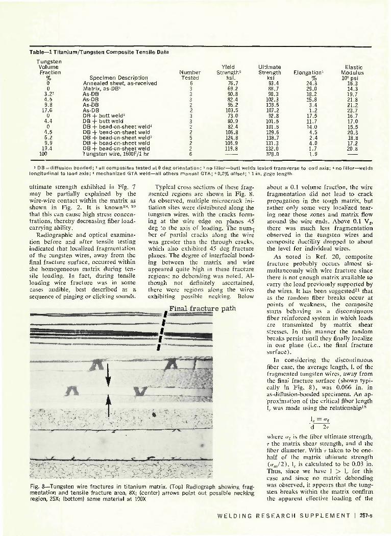
Typical cross sections of these fragmented regions are shown in Fig. 8. As observed, multiple microcrack initiation sites were distributed along the tungsten wires, with the cracks forming at the wire edge on planes 45 deg to the axis of loading. The num-j ber of partial cracks along the wire was greater than the through cracks, which also exhibited 45 deg fracture planes. The degree of interfacial bonding between the matrix and wire appeared quite high in these fracture regions; no debonding was noted. Although not definitely ascertained, there were regions along the wires exhibiting possible necking. Below
Final fracture path
about a 0.1 volume fraction, the wire fragmentation did not lead to crack propagation in the tough matrix, but rather only some very localized tearing near those zones and matrix flow around the wire ends. Above 0.1 Vf, there was much less fragmentation observed in the tungsten wires and composite ductility dropped to about the level for individual wires.
As noted in Ref. 20, composite fracture probably occurs almost simultaneously with wire fracture since there is not enough matrix available to carry the load previously supported by the wires. It has been suggested21 that as the random fiber breaks occur at points of weakness, the composite starts behaving as a discontinuous fiber reinforced system in which loads are transmitted by matrix shear stresses. In this manner the random breaks persist until they finally localize in one plane (i.e., the final fracture surface).
In considering the discontinuous fiber case, the average length, 1, of the fragmented tungsten wires, away from the final fracture surface (shown typically in Fig. 8) , was 0.066 in. in as-diffusion-bonded specimens. An approximation of the critical fiber length I,, was made using the relationship18
lc = °f
Fig. 8—Tungsten wire fractures in titanium matrix. (Top) Radiograph showing fragmentation and tensile fracture area, 8X; (center) arrows point out possible necking region, 25X; (bottom) same material at 100X
where at is the fiber ultimate strength, T the matrix shear strength, and d the fiber diameter. With r taken to be one-half of the matrix ultimate strength (cr„,/2), 1(. is calculated to be 0.03 in. Thus, since we have 1 > 1,. for this case and since no matrix debonding was observed, it appears that the tungsten breaks within the matrix confirm the apparent effective loading of the
W E L D I N G R E S E A R C H S U P P L E M E N T | 257-s

fibers and the good bonding achieved between fiber and matrix.
In the tensile fracture surface of a manually welded Ti-9% W specimen, as shown by the scanning electron micrograph in Fig. 9, reduced diameter tungsten wires, weld porosity and dimple rupture surface of the relatively ductile matrix are readily seen.
Debonding between the matrix and
wires along the final fracture plane was typical in all conditions, as shown in Fig. 10. The debond region may be generally characterized as having considerable peripheral fracture in the tungsten wire (probably through localized recrystallization areas) immediately adjacent to the prior matrix-wire interface. Ultimate tensile fracture of the tungsten wires is, we be-
s
Fig. 9—Fracture surface of Ti-9% W composite-manual GTA welded specimen, as shown by scanning electron micrograph—SEM
Fig. 10—Interfacial debonding and fracture region in Ti-9% W manual weld (SEM)
lieve, to be followed by wire/matrix debonding or shear failure, as the matrix strains to fracture.
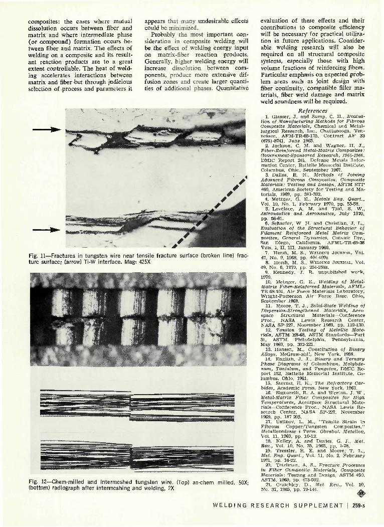
A subsequent optical micrograph showing this effect is given in Fig. 11. In this longitudinal view of the tungsten wire near the fracture surface, it appears that the reaction zone between the matrix and wire is still intact. Fracture occurs within the wires first, apparently, along 45 deg planes, followed by separation of the tungsten into longitudinal segments. This may indicate that the titanium-tungsten interfacial solid solution is strong enough to resist shearing thereby enhancing composite strength.
Joint Preparation Some consideration was given to
the problem of fiber discontinuity that arises in attempting to produce butt joints in composites. It has been pointed out10 that a planar interface will be created if two flush ends of a composite sheet are butted. A possible solution for improving joint efficiency consists of intermeshing protruding fibers before welding to provide fiber overlap and continuity. The results of a preliminary attempt are shown in Fig. 12, where a Ti-10% W composite was chemically milled to remove 10 mils from the edges and subsequently butt welded. The radiograph shows the overlap zone after manual fusion welding without filler wire addition. Tensile testing of this type of butt-weld specimen resulted in fracture occurring outside the weld-joint area. On butt-welded composites that were not intermeshed, the use of a slight amount of weld metal reinforcement also caused fracture away from the weld zone.
It is obvious that intermeshing reinforcing fibers is a limited practical approach to increasing joint efficiency, the degree of difficulty being proportional to volume content and component size. Typical problems could include difficulty of meshing, fiber damage and fiber contact. In view of these factors, however, the approach may be viable in certain cases.
Conclusions The general weldability of two ti
tanium matrix composites has been demonstrated on a limited basis. Up to about 0.2 volume fraction, the titanium-tungsten wire composites displayed reasonably normal welding characteristics. The titanium-graphite filament composites were also weldable but only with lower filament volume fractions and where the matrix laminates were well diffusion-bonded.
It appears that on a broader basis these results might be applied to more general categories of metal-matrix
258-s I MAY 1972
composites: the cases where mutual dissolution occurs between fiber and matrix and where intermediate phase (or compound) formation occurs between fiber and matrix. The effects of welding on a composite and its resultant reaction products are to a great extent controllable. The heat of weld^ ing accelerates interactions between matrix and fiber but through judicious selection of process and parameters it
appears that many undesirable effects could be minimized.
Probably the most important consideration in composite welding will be the effect of welding energy input on matrix-fiber reaction products. Generally, higher welding energy will increase dissolution between components, produce more extensive diffusion zones and create larger quantities of additional phases. Quantitative
Fig. 11—Fractures in tungsten wire near tensile fracture surface (broken line) fracture surface; (arrow) Ti-W interface. Mag: 425X
Fig. 12—Chem-milled and intermeshed tungsten wire. (Top) as-chem milled, 50X; (bottom) radiograph after intermeshing and welding, 2X
evaluation of these effects and their contributions to composite efficiency will be necessary for practical utilization in future applications. Considerable welding research will also be required on all structural composite systems, especially those with high volume fractions of reinforcing fibers. Particular emphasis on expected problem areas such as joint design with fiber continuity, compatible filler materials, fiber weld damage and matrix weld soundness will be required.
References 1. Glasser, J. and Sump, C. H., Evalua
tion of Manufacturing Methods for Fibrous Composite Materials, Chemical and Metallurgical Research. Inc . . Chat tanooga. Tennessee, AFM-TR-65-175, Contract A F 33 (675)-8741, J u n e 1965.
2. Jackson, C. M. and Wagner . H. J . , Fiber-Reinforced Metal-Matrix Composites: Government-Sponsored Research, 1961,-1966. DMIC Repor t 241, Defense Metals Informat ion Center, Bat tel le Memorial Ins t i tu te . Columbus, Ohio, Sep tember 1967.
3. Dallas. R. N.. Methods of Joining Advanced Fibrous Composites, Composite Materials: Testing and Design, ASTM S T P 460, American Society for Tes t ing and Materials . 1969, pp. 381-392.
4. Metzger, G. E., Metals Eng. Quart., Vol. 10, No. 1, F e b r u a r y 1970. pp. 55-58.
5. Lovelace, A. M. and Tsai, S. W., Astronautics and Aeronautics, Ju ly 1970, pp. 56-61.
6. Schaefer. W. H. and Christ ian, J . D., Evaluation of the Structural Behavior of Filament Reinforced Metal Matrix Composites, General Dynamics , Convair Div., San Diego. California. AFML-TR-69-36 Vols. I, I I , I I I , J a n u a r y 1969.
7. Hersh . M. S., WELDING JOURNAL, Vol. 47, No. 9, 1968, pp. 404-409S.
8. Hersh . M. S., WELDING JOURNAL, Vol. 49, No. 6. 1970, pp. 254-258S.
9. Kennedy. J. R. unpubl ished work, 1970.
10. Metzger. G. E., Welding of Metal-Matrix Fiber-Reinforced Materials, AFML-TR-68-101, Air Force Mater ia ls Labora to ry , Wr igh t -Pa t t e r son Air Force Base, Ohio, September 1968.
11. Moore, T. J . . Solid-State Welding of Dispersion-Strengthened Materials, Aerospace S t ruc tu ra l Materials—Conference P r o c . NASA Lewis Research Center, NASA SP-227, November 1969, pp. 119-130.
12. Tension Testing of Metallic Materials, ASTM E8-68. ASTM S t a n d a r d s — P a r t 31, ASTM, Phi ladelphia , Pennsylvania , May 1969, pp. 202-221.
13. Hansen, M., Constitution of Binary Alloys, McGraw-Hill , New York, 1958.
14. English, J. J . . Binary and Ternary Phase Diagrams of Columbium, Molybdenum, Tantalum, and Tungsten, DMIC Repor t 152, Bat tel le Memorial Ins t i tu te , Columbus. Ohio, 1961.
15. Storms, E. K., The Refractory Carbides, Academic Press , New York, 1967.
16. Signorell i , R. A. and Weeton, J . W., Metal-Matrix Fiber Composites for High Temperatures, Aerospace S t ruc tu ra l Materials—Conference P r o c , NASA Lewis Research Center, NASA SP-227, November 1969, pp. 187-205.
17. Ustinov, L. M.. "Tens i le S t ra in in Fibrous Copper /Tungs ten Composi tes ," Metallovedenie i Term. Obrabot. Metallov, Vol. 11. 1969. pp. 10-12.
18. Kelley, A. and Davies. G. J. , Met. Rev., Vol. 10, No. 35, 1965. pp. 1-78.
19. Tressler , R. E. and Moore ; T. L. , Met. Eng. Quart., Vol. 11, No. 2, F e b r u a r y 1971, pp. 16-22.
20. Tete lman, A. S., Fracture Processes in Fiber Composite Materials, Composite Materials: Tes t ing and Design, ASTM 460, ASTM, 1969. pp. 473-502.
21. Cratchley, D., Met. Rev., Vol. 10, No. 37, 1965, pp. 79-144. ^
W E L D I N G R E S E A R C H S U P P L E M E N T 1 259-s


