
G30�Driver�Assistance�SystemsContents1. Introduction.............................................................................................................................................................................................................................................1
1.1. Further� information.............................................................................................................................................................................................2
2. G30�Bus�Overview......................................................................................................................................................................................................................3
3. KAFAS................................................................................................................................................................................................................................................................63.1. Functional� limitations.......................................................................................................................................................................................8
4. Optional�Equipment�System...............................................................................................................................................................................10
5. Overview�of�Sensors..........................................................................................................................................................................................................11
6. Intelligent�Safety.......................................................................................................................................................................................................................136.1. Overview�of�the�configuration�menu...................................................................................................................................15
7. Collision�Warning.....................................................................................................................................................................................................................187.1. Warning�and�braking�function.......................................................................................................................................................19
7.1.1. Displays............................................................................................................................................................................................197.2. Operation........................................................................................................................................................................................................................207.3. Limits�of�the�system.....................................................................................................................................................................................21
8. Lane�Departure�Warning............................................................................................................................................................................................228.1. Active�steering�intervention..............................................................................................................................................................248.2. Deactivation�criteria.......................................................................................................................................................................................258.3. Limits�of�the�system.....................................................................................................................................................................................25
9. Blind�Spot�Detection.........................................................................................................................................................................................................269.1. Active�steering�intervention..............................................................................................................................................................289.2. Limits�of�the�system.....................................................................................................................................................................................29
10. Side�Collision�Avoidance...........................................................................................................................................................................................3010.1. Limits�of�the�system.....................................................................................................................................................................................33
11. Intersection�Warning.........................................................................................................................................................................................................3411.1. Functional�principle........................................................................................................................................................................................34
11.1.1. Warning............................................................................................................................................................................................3511.2. Limits�of�the�system.....................................................................................................................................................................................37
12. Road�Sign�Recognition.................................................................................................................................................................................................3812.1. Operation........................................................................................................................................................................................................................3812.2. Limits�of�the�system.....................................................................................................................................................................................39
13. Proactive�Driving�Assistant..................................................................................................................................................................................40

G30�Driver�Assistance�SystemsContents
13.1. Operation........................................................................................................................................................................................................................4113.2. Limits�of�the�system.....................................................................................................................................................................................41
14. Fatigue�and�Focus�Alert..............................................................................................................................................................................................4214.1. Operation........................................................................................................................................................................................................................4214.2. Limits�of�the�system.....................................................................................................................................................................................43
15. Night�Vision........................................................................................................................................................................................................................................4415.1. Operation........................................................................................................................................................................................................................4715.2. Limits�of�the�system.....................................................................................................................................................................................48
16. Cameras.....................................................................................................................................................................................................................................................4916.1. Surround�View........................................................................................................................................................................................................49
16.1.1. Automatic�camera�angle.......................................................................................................................................5016.1.2. Side�view.......................................................................................................................................................................................5016.1.3. Front�camera...........................................................................................................................................................................5016.1.4. Panorama�View....................................................................................................................................................................5016.1.5. Rear�view�camera.............................................................................................................................................................5416.1.6. Moving�camera�angle................................................................................................................................................54
16.2. Overview�of�exterior�camera�operating�menu.......................................................................................................5616.3. Assistant�function.............................................................................................................................................................................................57
16.3.1. Car�wash�view.......................................................................................................................................................................5816.3.2. Side�protection....................................................................................................................................................................5916.3.3. Door�opening�angle......................................................................................................................................................60
16.4. Remote�3D�View.................................................................................................................................................................................................6016.4.1. Functional�principle......................................................................................................................................................61
16.5. System�components....................................................................................................................................................................................6316.5.1. Front�camera...........................................................................................................................................................................6316.5.2. Top�view�camera...............................................................................................................................................................6416.5.3. Rear�view�camera.............................................................................................................................................................6516.5.4. TRSVC�control�unit.......................................................................................................................................................67
17. Park�Distance�Control.....................................................................................................................................................................................................6817.1. System�components....................................................................................................................................................................................6817.2. Auto�PDC.......................................................................................................................................................................................................................6917.3. Active�Park�Distance�Control..........................................................................................................................................................7017.4. Side�protection......................................................................................................................................................................................................70
17.4.1. Functional�principle......................................................................................................................................................7117.5. Operation........................................................................................................................................................................................................................7217.6. Deactivation�criteria.......................................................................................................................................................................................7217.7. Limits�of�the�system.....................................................................................................................................................................................73

G30�Driver�Assistance�SystemsContents18. Cross�Traffic�Alert..................................................................................................................................................................................................................74
18.1. Functional�principle........................................................................................................................................................................................7418.2. Cross�Traffic�Alert�Rear...........................................................................................................................................................................7518.3. Cross�Traffic�Alert�Front.........................................................................................................................................................................7518.4. Displays.............................................................................................................................................................................................................................7618.5. Operation........................................................................................................................................................................................................................7818.6. Limits�of�the�system.....................................................................................................................................................................................79
19. Parking�Maneuvering�Assistant....................................................................................................................................................................8019.1. Parallel�parking/perpendicular�parking.............................................................................................................................80
19.1.1. Curbside�parking...............................................................................................................................................................8019.1.2. Perpendicular�parking...............................................................................................................................................81
19.2. System�components....................................................................................................................................................................................8119.3. System�wiring�diagram.............................................................................................................................................................................8319.4. Control�unit..................................................................................................................................................................................................................8619.5. Functional�principle........................................................................................................................................................................................86
19.5.1. Personal�responsibility.............................................................................................................................................8719.6. Functional�prerequisites.........................................................................................................................................................................87
19.6.1. Measuring�parking�spaces................................................................................................................................8819.7. Operation........................................................................................................................................................................................................................89
19.7.1. Park�procedure.....................................................................................................................................................................9019.7.2. Deactivation�criteria......................................................................................................................................................90
19.8. Limits�of�the�system.....................................................................................................................................................................................91
20. Remote�Control�Parking..............................................................................................................................................................................................9220.1. Operation........................................................................................................................................................................................................................93
20.1.1. Cut-off�events........................................................................................................................................................................9520.2. Requirements�on�the�parking�space...................................................................................................................................9620.3. System�overview.................................................................................................................................................................................................9720.4. Limits�of�the�system.....................................................................................................................................................................................98
21. Cruise�Control................................................................................................................................................................................................................................9921.1. Introduction.................................................................................................................................................................................................................9921.2. Cruise�control�with�braking�function...................................................................................................................................99
21.2.1. Operation.......................................................................................................................................................................................9921.3. Active�Cruise�Control�with�Stop&Go�function.................................................................................................100
21.3.1. Operation..................................................................................................................................................................................107
22. Speed�Limit�Warning....................................................................................................................................................................................................11122.1. Operation....................................................................................................................................................................................................................111

G30�Driver�Assistance�SystemsContents23. Lateral�Guidance�Assistants...........................................................................................................................................................................112
23.1. Launch�timeline................................................................................................................................................................................................112
24. Lane�Keeping�&�Traffic�Jam�Assistants....................................................................................................................................11424.1. Functional�principle....................................................................................................................................................................................114
24.1.1. Hands-off-Detection...............................................................................................................................................11624.1.2. Functional�prerequisites...................................................................................................................................11624.1.3. Lane�change........................................................................................................................................................................11724.1.4. Function�logic....................................................................................................................................................................11724.1.5. Steering�interventions..........................................................................................................................................11824.1.6. Operation..................................................................................................................................................................................11924.1.7. Deactivation�criteria.................................................................................................................................................12124.1.8. Limits�of�the�system...............................................................................................................................................121
25. Active�Lane�Keeping�Assistant.................................................................................................................................................................12225.1. Side�Collision�Avoidance...................................................................................................................................................................122
25.1.1. Reduced�Side�Collision�Avoidance..................................................................................................12225.2. Lane�Departure�Warning...................................................................................................................................................................12325.3. Blind�Spot�Detection...............................................................................................................................................................................124
26. Evasion�Aid.....................................................................................................................................................................................................................................12526.1. Functional�principle....................................................................................................................................................................................12526.2. System�overview............................................................................................................................................................................................12826.3. Operation....................................................................................................................................................................................................................13026.4. Functional�prerequisites.....................................................................................................................................................................13026.5. Limits�of�the�system.................................................................................................................................................................................131

G30�Driver�Assistance�Systems1.�Introduction
1
The�most�versatile�range�of�Driver�Assistance�Systems�ever�for�a�BMW�model�was�launched�with�theintroduction�of�the�G12.
Numerous�innovative�systems�have�been�introduced�and�have�opened�the�way�for�highly�automateddriving.�It�is�planned�that�the�technical�prerequisites�will�have�been�laid�for�an�“Autobahn�pilot”�by�2020so�that�we�will�be�able�to�offer�highly�automated�driving�for�the�first�time.
At�present,�however,�the�appropriate�legal�foundations�have�not�been�laid�for�autonomous�driving.
Drivers�are�still�expected�to�drive�with�both�hands�on�the�steering�wheel,�although�systems�are�alreadyin�place�to�drive�the�vehicle�autonomously�in�certain�situations.
The�already�comprehensive�range�of�Driver�Assistance�Systems�has�been�expanded�again�in�the�G30to�include�revolutionary�new�systems.�Systems�such�as�Intersection�Warning�are�in�use.�Evasion�Aidis�presented�for�the�first�time�with�the�launch�of�the�G30.�For�even�greater�convenience,�the�restarttime�on�the�Active�Cruise�Control�Stop&Go�function�has�been�increased,�and�the�detection�of�moreinformation�and�the�incorporation�of�further�sensors�has�made�more�driver-like�driving�characteristicspossible.
A�further�feature�among�the�camera�systems�is�the�Remote�3D�View�function�which�makes�it�possibleto�transmit�an�image�of�the�parked�vehicle�to�mobile�devices.
The�interplay�between�the�varied�and�intelligent�Driver�Assistance�Systems�supports�the�driver�inevery�respect;�from�making�driving�more�comfortable�to�providing�the�reassuring�feeling�of�safety�on�allroads.
The�Driver�Assistance�Systems�help�to�make�the�driver's�life�easier�by:
• Providing�the�driver�with�information• Prompting�the�driver�with�suggestions• Automatically�intervening�in�the�driving�process
This�reference�manual�contains�an�overview�of�all�the�Driver�Assistance�Systems�used�in�the�G30:
• Camera-based�collision�warning• Frontal�Collision�Warning�with�City�Collision�Mitigation• Daytime�Pedestrian�Protection• Lane�Departure�Warning• Blind�Spot�Detection• Side�Collision�Avoidance• Intersection�Warning• Road�Sign�Recognition• Proactive�Driving�Assistant• Fatigue�and�Focus�Alert• Night�vision• Camera�systems• Park�Distance�Control

G30�Driver�Assistance�Systems1.�Introduction
2
• Cross�Traffic�Alert• Parking�Maneuvering�Assistant• Remote�Control�Parking• Speed�control• Speed�limit�warning• Traffic�Jam�Assistant• Active�Lane�Keeping�Assistant�with�Side�Collision�Avoidance• Evasion�Aid
Identifying�road�users�driving�ahead�as�well�as�detecting�objects�and�lane�edges�are�among�the�mostimportant�prerequisites�for�the�Driver�Assistance�Systems.�This�applies�not�only�for�the�far�range�butalso�the�close�range.
The�optional�functions�available�for�the�G30�are�implemented�either�as�camera-based�systems�witha�shared�camera�and�integrated�control�unit,�or�using�sensors�such�as�ultrasonic�or�radar�sensors.Evaluation�signals�provided�by�various�control�units�(for�example,�from�the�Advanced�Crash�SafetyModule�(ACSM))�are�also�taken�into�consideration.
1.1.�Further�informationThe�Driver�Assistance�Systems�in�the�new�BMW�5�Series�builds�on�those�of�the�BMW�7�Series�G12.Accompanying�information�for�the�topics�listed�below�may�be�found�in�the�“G12�Driver�AssistanceSystems”�reference�manual.
Topic reference�manualProactive�Driving�Assistant G12�Driver�Assistance�Systems�(section�12)Auto�PDC G12�Driver�Assistance�Systems�(section�16.2)Active�Park�Distance�Control G12�Driver�Assistance�Systems�(section�16.3)Remote�Control�Parking G12�Driver�Assistance�Systems�(section�17)Parking�Maneuvering�Assistant G12�Driver�Assistance�Systems�(section�19)Hands-off-Detection G12�Driver�Assistance�Systems�(section�23.1.1)
For�more�information�on�the�operating�concept�of�the�Driver�Assistance�Systems,�please�refer�to�theOwner's�Handbook.

G30�Driver�Assistance�Systems2.�G30�Bus�Overview
3
G30�Bus�overview
G30�Driver�Assistance�Systems2.�G30�Bus�Overview
4
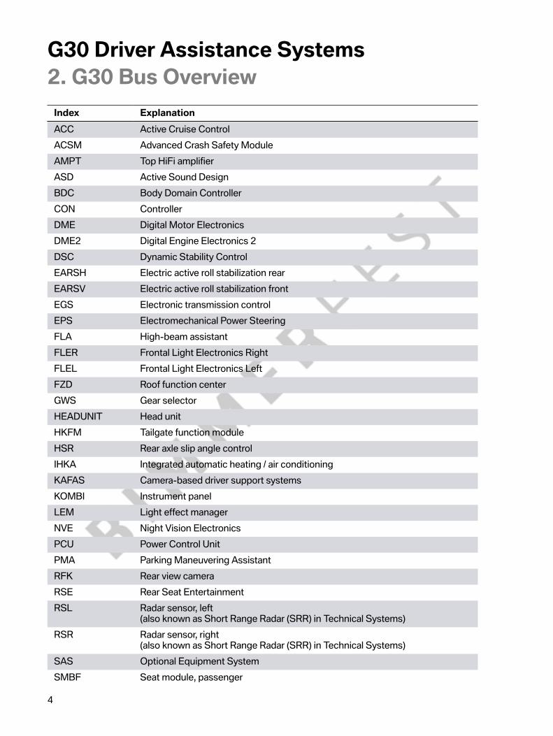
Index ExplanationACC Active�Cruise�ControlACSM Advanced�Crash�Safety�ModuleAMPT Top�HiFi�amplifierASD Active�Sound�DesignBDC Body�Domain�ControllerCON ControllerDME Digital�Motor�ElectronicsDME2 Digital�Engine�Electronics�2DSC Dynamic�Stability�ControlEARSH Electric�active�roll�stabilization�rearEARSV Electric�active�roll�stabilization�frontEGS Electronic�transmission�controlEPS Electromechanical�Power�SteeringFLA High-beam�assistantFLER Frontal�Light�Electronics�RightFLEL Frontal�Light�Electronics�LeftFZD Roof�function�centerGWS Gear�selectorHEADUNIT Head�unitHKFM Tailgate�function�moduleHSR Rear�axle�slip�angle�controlIHKA Integrated�automatic�heating�/�air�conditioningKAFAS Camera-based�driver�support�systemsKOMBI Instrument�panelLEM Light�effect�managerNVE Night�Vision�ElectronicsPCU Power�Control�UnitPMA Parking�Maneuvering�AssistantRFK Rear�view�cameraRSE Rear�Seat�EntertainmentRSL Radar�sensor,�left
(also�known�as�Short�Range�Radar�(SRR)�in�Technical�Systems)RSR Radar�sensor,�right
(also�known�as�Short�Range�Radar�(SRR)�in�Technical�Systems)SAS Optional�Equipment�SystemSMBF Seat�module,�passenger

G30�Driver�Assistance�Systems2.�G30�Bus�Overview
5
Index ExplanationSMBFH Seat�module,�passenger,�rearSMFA Seat�module,�driverSMFAH Seat�module,�driver,�rearSPNMHL Seat�pneumatics�module�back�leftSPNMHR Seat�pneumatics�module�back�rightSPNMVL Seat�pneumatics�module�front�leftSPNMVR Seat�pneumatics�module�front�rightSWW Blind�Spot�Detection�(primary)
(also�known�as�Short�Range�Radar�(SRR)�in�Technical�Systems)SWW2 Blind�Spot�Detection�(secondary)
(also�known�as�Short�Range�Radar�(SRR)�in�Technical�Systems)TCB Telematic�Communication�BoxTRSVC Top�Rear�Side�View�CameraVDP Vertical�Dynamic�PlatformVTG Transfer�boxWCA Wireless�charging�stationZGM Central�gateway�module1 Start-up�node�control�units�for�starting�and
synchronizing�the�FlexRay�bus�system2 Control�units�with�wake-up�authorisation3 Control�units�also�connected�at�terminal�15WUP

G30�Driver�Assistance�Systems3.�KAFAS
6
Since�the�requirements�on�the�KAFAS�camera�have�further�increased�in�the�new�BMW�5�Series,�theKAFAS�stereo�camera,�familiar�from�the�G12,�is�also�used�on�the�G30.
KAFAS�stereo�camera
The�KAFAS�stereo�camera�is�calibrated�within�a�distance�of�approximately�1.25�mi�(2�km)�duringdriving.
The�KAFAS�stereo�camera�is�the�key�element�of�the�following�systems:
• Frontal�Collision�Warning�with�City�Collision�Mitigation• Daytime�Pedestrian�Protection• Lane�Departure�Warning• Road�Sign�Recognition
The�KAFAS�stereo�camera�plays�a�supporting�role�in�the�following�systems:
• Active�Cruise�Control�With�Stop&Go�Function• Traffic�Jam�Assistant• Active�Lane�Keeping�Assistant�with�Side�Collision�Avoidance• Intersection�Warning
The�KAFAS�stereo�camera�installed�in�the�mirror�base�of�the�interior�mirror�on�the�windscreenmonitors�the�area�in�front�of�the�vehicle.

G30�Driver�Assistance�Systems3.�KAFAS
7
G30�KAFAS�stereo�camera
Index Explanation1 KAFAS�stereo�camera2 Rain‐light‐solar-condensation�sensor3 Photosensor�for�electrochromic�interior�mirror
The�KAFAS�stereo�camera�has�a�detection�range�of�up�to�approximately�130�ft�(40 m)�ahead�of�thevehicle�and�up�to�approximately�16�ft�(5 m)�in�front�of�the�vehicle�on�the�right�and�left.�The�overalldetection�range�of�the�KAFAS�stereo�camera�is�approximately�1600�ft�(500 m).
The�tasks�of�the�KAFAS�stereo�camera�are:
• Person�recognition• Road�Sign�Recognition• Lane�detection

G30�Driver�Assistance�Systems3.�KAFAS
8
KAFAS�stereo�camera�detection�range
3.1.�Functional�limitationsThe�function�of�the�KAFAS�stereo�camera�and�thus�the�function�of�the�corresponding�DriverAssistance�Systems�may�be�impaired�due�to�the�physical�limits�of�the�optical�systems,�for�example�inthe�following�situations:
• Heavy�fog,�rain,�spray�or�snow.• Strong�light�in�the�camera�lens.• If�the�field�of�view�of�the�KAFAS�stereo�camera�or�the�windscreen�is�dirty.• On�tight�bends.• If�boundary�lines�are�missing,�worn,�poorly�visible,�converging�or�diverging,�or�not�clearly
recognizable,�as�may�be�the�case�when�road�construction�is�being�performed.• If�boundary�lines�are�covered�by�snow,�ice,�dirt�or�water.• If�boundary�lines�are�covered�by�objects.• If�driving�at�close�proximity�to�a�vehicle�driving�ahead.• If�the�windscreen�in�front�of�the�interior�mirror�is�misted�over,�soiled�or�covered�by�stickers,�e.g.
parking�permits,�etc.• Up�to�10�seconds�after�driving�readiness�is�activated�via�the�start/stop�button.• During�the�calibration�process�for�the�KAFAS�stereo�camera�immediately�after�vehicle�delivery
or�a�camera�change.

G30�Driver�Assistance�Systems3.�KAFAS
9
Example�of�limits�of�the�KAFAS�stereo�camera
Due�to�functional�limitations�and�system�restrictions�it�may�transpire�that�warnings�and�alerts�are�notissued,�are�issued�too�late�or�are�unwarranted.�Therefore,�be�attentive�in�order�to�be�able�to�activelyintervene�at�any�time.�Otherwise,�there�is�a�risk�of�an�accident.

G30�Driver�Assistance�Systems4.�Optional�Equipment�System
10
The�G30�also�features�the�Optional�Equipment�System�(SAS)�control�unit�which�is�already�familiar�andwhich�provides�a�host�of�Driver�Assistance�System�functions.
Possible�functions:
• Frontal�Collision�Warning�with�City�Collision�Mitigation• Daytime�Pedestrian�Protection• Dynamic�Brake�Control• Distance�information• Cruise�control�with�braking�function• Active�Cruise�Control�with�Stop&Go�function• Traffic�Jam�Assistant• Active�Lane�Keeping�Assistant�with�Side�Collision�Avoidance• Evasion�Aid• Speed�Limit�Information• Blind�Spot�Detection• Lane�Departure�Warning• Cross�Traffic�Alert• Intersection�Warning• Parking�Maneuvering�Assistant• Remote�Control�Parking• Proactive�Driving�Assistant
G30�Control�unit�for�Optional�Equipment�System�(SAS)

G30�Driver�Assistance�Systems5.�Overview�of�Sensors
11
The�graphic�below�provides�an�overview�of�the�main�sensors�used�in�the�G30�for�the�Driver�AssistanceSystems�and�shows�their�installation�locations.
G30�Overview�of�sensors

G30�Driver�Assistance�Systems5.�Overview�of�Sensors
12
Index Explanation1 Control�unit�for�radar�sensor,�right�(RSR)�(also�known�as
Short�Range�Radar�(SRR)�in�Technical�Systems)2 KAFAS�stereo�camera3 Blind�Spot�Detection�(primary)�(also�known�as
Short�Range�Radar�(SRR)�in�Technical�Systems)4 Blind�Spot�Detection�(secondary)�(also�known�as
Short�Range�Radar�(SRR)�in�Technical�Systems)5 Control�unit�for�radar�sensor,�left�(RSL)�(also�known�as
Short�Range�Radar�(SRR)�in�Technical�Systems)6 Active�Cruise�Control�(ACC)�(also�known�as
Full�Range�Radar�Sensor�(FRR)�in�Technical�Systems)7 Night�Vision�camera

G30�Driver�Assistance�Systems6.�Intelligent�Safety
13
Due�to�the�ever�increasing�amount�of�traffic�on�our�roads,�Driver�Assistance�Systems�in�vehiclescontinue�to�gain�in�importance.�The�systems�have�different�functions:�some�gather�information�to�helpthe�driver�in�the�decision-making�process,�while�others�take�on�the�driver's�roles�in�monotonous�trafficsituations�or�intervene�to�make�corrections.
The�Driver�Assistance�Systems�support�the�driver�on�highways,�single-lane�roads�and�in�urbanenvironments.�Systems�such�as�the�Daytime�Pedestrian�Protection�provide�support�in�urban�traffic,�forinstance.�Night�Vision�can�assist�the�driver�when�driving�on�single-lane�roads�with�adjacent�woodland(deer�crossings,�etc.).�The�Lane�Departure�Warning�and�Blind�Spot�Detection�as�well�as�the�SideCollision�Avoidance�provide�even�more�safety�in�traffic.�Accidents�can�be�avoided�through�automaticbrake�interventions,�active�steering�interventions�or�a�combination�of�both.
Once�more,�new�Driver�Assistance�Systems�are�being�presented�with�the�launch�of�a�new�BMW�5Series.�The�Intelligent�Safety�menu�has�been�adapted�to�the�new�systems�accordingly.
Depending�on�the�vehicle�equipment,�the�driver�has�a�multitude�of�individual�configurations�available�inthe�Intelligent�Safety�menu.�For�some�systems,�no�configuration�options�are�provided�by�the�operatingconcept.�Thus,�for�example,�Evasion�Aid�can�only�be�deactivated�by�switching�off�all�Intelligent�Safetysystems�(ALL OFF).
Depending�on�the�vehicle�equipment,�Intelligent�Safety�consists�of�one�or�several�systems,�which�canhelp�to�avoid�a�potential�collision.�The�following�systems�are�offered�in�the�G30:
• Daytime�Pedestrian�Protection• Night�Vision�with�person�and�animal�recognition• Lane�Departure�Warning• Blind�Spot�Detection• Side�Collision�Avoidance• Evasion�Aid• Frontal�Collision�Warning�with�City�Collision�Mitigation
The�Intelligent�Safety�button,�already�familiar�from�other�BMW�models,�enables�the�Driver�AssistanceSystems�to�be�operated�centrally.�This�means�the�systems�can�be�switched�on�or�off�using�a�buttonand�the�submenu�can�be�called�up�to�personalize�the�settings.

G30�Driver�Assistance�Systems6.�Intelligent�Safety
14
G30�Intelligent�Safety�button
Index Explanation1 Intelligent�Safety�button
Press�button
• The�"Intelligent�Safety"�menu�is�displayed�on�the�Central�Information�Display�(CID).Settings�can�be�made�using�the�controller.�The�individual�settings�are�stored�for�the�respectiveID�transmitter�used.
Press�and�release�button
• When�all�Intelligent�Safety�systems�are�switched�on:Intelligent�Safety�systems�are�switched�off�individually�depending�on�the�individual�setting.
• When�all�Intelligent�Safety�systems�are�not�switched�on:All�Intelligent�Safety�systems�are�switched�on.
Press�button�for�an�extended�period
• All�Intelligent�Safety�systems�are�switched�off.

G30�Driver�Assistance�Systems6.�Intelligent�Safety
15
G30�Status�indicator�light�(Intelligent�Safety�button)
Index ExplanationA All�Intelligent�Safety�systems�are�switched�onB Some�Intelligent�Safety�systems�are�switched�off
or�sub-function�settings�have�been�changedC All�Intelligent�Safety�systems�are�switched�off
The�Intelligent�Safety�systems�are�automatically�active�after�each�engine�start�via�the�START-STOPbutton.
6.1.�Overview�of�the�configuration�menuThe�system�is�operated�by�pressing�the�Intelligent�Safety�button�and�using�a�menu�to�configure�theIntelligent�Safety�systems�on�the�Central�Information�Display�(CID).
G30�Intelligent�Safety�overview�configuration�menu

G30�Driver�Assistance�Systems6.�Intelligent�Safety
16
Index Explanation1 "Intelligent�Safety"�configuration�menu2 "ALL�ON"�selection3 Note�for�the�driver:�the�colored�circle�shows�the�driver�the�activation�status�of
the�Intelligent�Safety�systems.�The�color�of�the�circle�always�matches�the�colorof�the�Intelligent�Safety�button�indicator�light.
4 "INDIVIDUAL"�selection5 "ALL�OFF"�selection6 "Configure�INDIVIDUAL"7 Note�for�the�driver:�In�this�example�the�information�is�being�provided�that�the
driver�must�hold�the�controller�down�for�three�seconds�after�selecting�the�ALLOFF�menu�item�to�deactivate�the�Intelligent�Safety�systems.
"ALL�ON"
• All�Intelligent�Safety�systems�are�switched�on.�The�basic�settings�are�activated�for�thesubfunctions,�for�example�the�warning�time�setting.�The�Intelligent�Safety�button�lightsup�green.
"INDIVIDUAL"
• The�Intelligent�Safety�systems�are�switched�on�in�accordance�with�the�individual�settings.Depending�on�the�vehicle�equipment,�the�Intelligent�Safety�systems�can�be�configuredindividually.�The�individual�settings�are�activated�and�stored�for�the�respective�ID�transmitterused.
G30�Intelligent�Safety�("Configure�INDIVIDUAL"�selection)
Index Explanation1 "Intelligent�Safety"�configuration�menu2 "Configure�INDIVIDUAL"
G30�Driver�Assistance�Systems6.�Intelligent�Safety
17
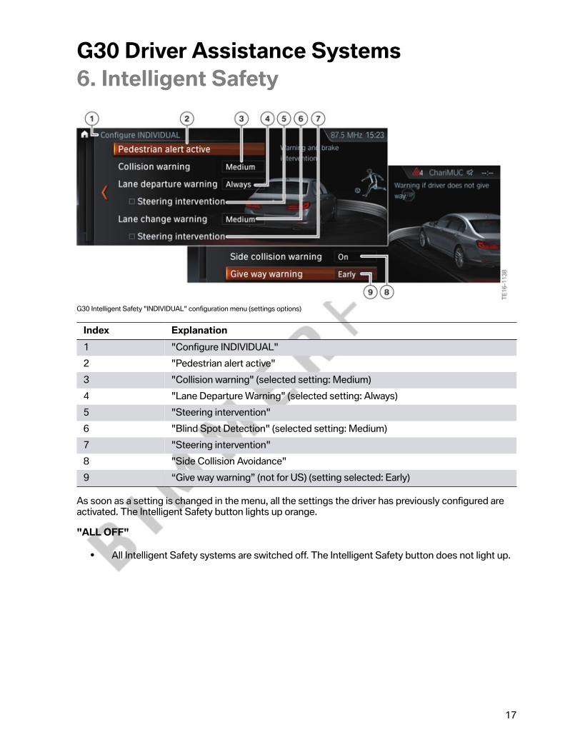
G30�Intelligent�Safety�"INDIVIDUAL"�configuration�menu�(settings�options)
Index Explanation1 "Configure�INDIVIDUAL"2 "Pedestrian�alert�active"3 "Collision�warning"�(selected�setting:�Medium)4 "Lane�Departure�Warning"�(selected�setting:�Always)5 "Steering�intervention"6 "Blind�Spot�Detection"�(selected�setting:�Medium)7 "Steering�intervention"8 "Side�Collision�Avoidance"9 “Give�way�warning”�(not�for�US)�(setting�selected:�Early)
As�soon�as�a�setting�is�changed�in�the�menu,�all�the�settings�the�driver�has�previously�configured�areactivated.�The�Intelligent�Safety�button�lights�up�orange.
"ALL�OFF"
• All�Intelligent�Safety�systems�are�switched�off.�The�Intelligent�Safety�button�does�not�light�up.

G30�Driver�Assistance�Systems7.�Collision�Warning
18
The�camera-based�collision�warning�is�part�of�the�Active�Driving�Assistant�optional�equipment(OE 5AS)�in�the�G30�and�is�implemented�using�the�KAFAS�stereo�camera.
The�collision�warning�in�the�new�BMW�5�Series�contains�the�familiar�Frontal�Collision�Warning�withCity�Collision�Mitigation�and�Daytime�Pedestrian�Protection�functions.
In�vehicles�with�the�Active�Driving�Assistant�Plus�optional�equipment�(OE�5AT),�the�cruise�control�radarsensor�is�also�used�to�control�the�collision�warning.
G30�Fusion�of�the�KAFAS�stereo�camera/ACC�radar�sensor�(diagram�of�the�monitoring�ranges)
Index Explanationa Close�rangeb Long�distance1 KAFAS�stereo�camera�detection�range2 Detection�range�of�the�radar�sensor
Vehicles�with�the�Active�Driving�Assistant�Plus�optional�equipment�(OE 5AT)�have�the�Active�CruiseControl�with�Stop&Go�function�integrated�as�standard.
The�system�warns�the�driver�in�situations�where�a�collision�is�imminent.�The�early�warning,�a�visualsignal,�is�issued�first�to�draw�the�driver's�attention�to�the�situation.�If�the�situation�becomes�morecritical,�an�acute�early�warning�in�the�form�of�a�visual�and�acoustic�signal�is�issued.�The�nature�of�thewarning�is�such�that�the�driver�can�still�prevent�a�collision�providing�he�acts�quickly.
The�collision�warning�is�dependent�on�the�vehicle's�own�driving�speed.�The�distance�measured�for�thecollision�warning�is�significantly�lower�than�the�legally�required�minimum�distance.�It�is�therefore�theresponsibility�of�the�driver�to�adhere�to�the�legal�minimum�distance.

G30�Driver�Assistance�Systems7.�Collision�Warning
19
7.1.�Warning�and�braking�function
7.1.1.�Displays
Symbols ExplanationEarly�warning:
• Vehicle�symbol�lights�up�red• Increase�distance�and�brake�if�necessary
Acute�warning:
• Vehicle�symbol�flashes�red�and�a�signalsounds
• Request�for�intervention�by�braking�andevasive�action,�if�required
Acute�warning:
• Person�symbol�flashes�red�and�a�signal�sounds• Request�for�intervention�by�braking�and
evasive�action,�if�required
The�acute�warning�does�not�relieve�the�driver�of�his�responsibility�to�adapt�the�speed�and�driving�styleto�the�traffic�conditions.
Additional�information�regarding�the�collision�warning�may�be�found�in�the�“G12�Driver�AssistanceSystems”�reference�manual�(sections�7.1�and�7.2).

G30�Driver�Assistance�Systems7.�Collision�Warning
20
7.2.�OperationThe�collision�warning�and�pedestrian�warning�are�switched�on�and�off�using�the�Intelligent�Safetybutton.
G30�Intelligent�Safety�button
Index Explanation1 Intelligent�Safety�button
The�point�at�which�the�early�collision�warning�is�issued�can�be�configured�in�the�"Intelligent�Safetysystems"�menu�on�the�Central�Information�Display�(CID).
The�acute�warning�cannot�be�deactivated�separately.�The�timing�of�the�acute�warning�also�cannotbe�adjusted.�If�the�acute�warning�is�not�to�be�issued,�the�"collision�warning"�front�protective�functionmust�be�deactivated.�The�collision�warning�can�be�switched�off�by�holding�down�the�Intelligent�Safetybutton.
It�is�also�not�possible�to�configure�or�deactivate�the�pedestrian�warning�separately.�The�"collisionwarning"�front�protective�function�must�be�also�deactivated�by�holding�down�the�Intelligent�Safetybutton�in�order�to�deactivate�the�pedestrian�warning�function.

G30�Driver�Assistance�Systems7.�Collision�Warning
21
7.3.�Limits�of�the�system
The�collision�warning�has�a�limited�capacity�for�detection.
As�a�result,�incorrect�or�delayed�warnings�may�occur.�It�is�possible�the�following�vehicles�are�notdetected:
• A�slow�vehicle�when�driving�off�at�high�speed.• Vehicles�that�suddenly�swerve�or�decelerate�rapidly.• Vehicles�with�an�unusual�rear�view�or�with�insufficiently�visible�rear�lights.• Partially�concealed�vehicles.• Two-wheeled�vehicles�travelling�ahead.
Functional�limitations
The�function�of�the�KAFAS�stereo�camera�and�thus�the�function�of�the�corresponding�DriverAssistance�Systems�may�be�impaired�in�the�following�situations,�for�example:
• Heavy�fog,�rain,�spray�or�snow.• Insufficient�light.• Strong�light�in�the�camera�lens.• If�the�field�of�view�of�the�KAFAS�stereo�camera�or�the�windscreen�is�dirty.• On�sharp�bends.• With�pedestrians�up�to�approximately�2.5�ft�(80 cm)�in�height.• Up�to�10 seconds�after�engine�start�via�the�START-STOP�button.• During�the�calibration�process�for�the�KAFAS�stereo�camera�immediately�after�vehicle�delivery
or�a�camera�change.
Due�to�functional�limitations�and�system�restrictions�it�may�transpire�that�warnings�and�alerts�are�notissued,�are�issued�too�late�or�are�unwarranted.�Therefore,�be�attentive�in�order�to�be�able�to�activelyintervene�at�any�time.�Otherwise,�there�is�a�risk�of�an�accident.

G30�Driver�Assistance�Systems8.�Lane�Departure�Warning
22
The�Lane�Departure�Warning�is�an�element�of�the�Active�Driving�Assistant,�optional�equipment�(OE5AS)�and�the�Active�Driving�Assistant�Plus,�optional�equipment�(OE�5AT).
The�Lane�Departure�Warning�detects�lane�markings�from�a�speed�of�approximately�43�mph�(70 km/h)and�warns�the�driver�against�unintentionally�leaving�the�lane.
The�information�required�about�usable�roadway�and�lane�markings�is�provided�by�the�KAFAS�stereocamera.�Based�on�the�calculated�positions,�lane�edges�and�curves�in�relation�to�the�relative�position�ofthe�driver's�vehicle,�a�corresponding�warning�is�issued.
If�the�driver�crosses�the�lane�marking�unintentionally�(without�using�the�turn�indicator)�or�leaves�theroad�boundary,�he�is�warned�abruptly�by�the�steering�wheel�vibrating�gently�and�has�the�opportunityto�react�accordingly.�The�vibration�in�the�steering�wheel�can�be�compared�to�the�vibration�effect�whendriving�over�a�profiled�road�marking.
In�the�settings�menu�the�driver�can�set�the�desired�strength�of�the�abrupt�warnings�on�the�steeringwheel�via�the�iDrive.
G30�Steering�wheel�vibration�settings�menu�on�CID
Index Explanation1 Steering�wheel�vibration�menu2 Additional�note�for�the�driver3 "Strong"4 "Medium"5 "Light"
If�the�driver�uses�the�turn�indicator�when�moving�across�to�another�lane,�the�Lane�Departure�Warningrecognizes�that�this�is�an�intentional�lane�change�and�a�warning�is�not�issued.

G30�Driver�Assistance�Systems8.�Lane�Departure�Warning
23
The�Lane�Departure�Warning�can�be�configured�individually�in�the�Intelligent�Safety�system�submenu.
G30�Intelligent�Safety�view�on�the�CID�(Lane�Departure�Warning)
Index Explanation1 "Configure�INDIVIDUAL"�menu2 "Lane�Departure�Warning"�(selected�setting:�Always)3 "Lane�Departure�Warning"�(settings�options:�Always,�Reduced,�Off)
The�individual�settings�applied�by�the�driver�are�saved�for�the�driver�profile�currently�in�use.
Displays�in�the�Instrument�Cluster�(KOMBI)
Symbol ExplanationAt�least�one�lane�boundary�has�been�detectedand�warnings�can�be�issued.

G30�Driver�Assistance�Systems8.�Lane�Departure�Warning
24
8.1.�Active�steering�interventionIn�vehicles�with�the�Side�Collision�Avoidance�(included�in�Active�Driving�Assistant�Plus,�optionalequipment�OE 5AT),�the�driver�is�assisted�by�another�measure�known�as�"active�steering�intervention".
If�the�driver�does�not�react�to�the�warning�issued�by�the�Lane�Departure�Warning�system�and�crossesthe�lane�marking,�he�is�assisted�to�stay�in�lane�by�a�brief�active�steering�intervention.
G30�Lane�Departure�Warning�(active�steering�intervention)
The�active�steering�intervention�can�be�felt�on�the�steering�wheel,�but�can�be�overridden�by�the�driverat�any�time.�If�the�driver�does�override�the�intervention,�the�active�steering�intervention�is�cancelled.
The�"steering�intervention"�for�the�Lane�Departure�Warning�can�be�switched�on�and�off�via�the�iDrivemenu�in�vehicles�with�the�Side�Collision�Avoidance�by�making�the�following�selection�via�the�controller:
• "My�Vehicle"• "Vehicle�settings"• "Intelligent�Safety"• "Steering�intervention"
The�configuration�menu�can�be�accessed�quickly�by�pressing�the�Intelligent�Safety�button.
G30�Intelligent�Safety�view�on�the�CID�(Lane�Departure�Warning�with�active�steering�intervention)

G30�Driver�Assistance�Systems8.�Lane�Departure�Warning
25
Index Explanation1 "Configure�INDIVIDUAL"�menu2 "Steering�intervention"�(switching�the�steering�intervention
for�Lane�Departure�Warning�on�and�off)
Steering�interventions�are�not�initiated�when�the�trailer�socket�is�in�use,�such�as�when�a�trailer�is�beingtowed�or�a�bicycle�carrier�is�mounted.
8.2.�Deactivation�criteriaThe�Lane�Departure�Warning�is�available�at�a�speed�range�from�43�–�130�mph�(70 km/h�–�210 km/h).
A�warning�is�not�issued�in�the�following�situations:
• Use�of�the�turn�indicator• In�construction�zones• Lane�is�narrower�than�8½�ft�(2.60 m)
The�warning�is�cancelled�in�the�following�situations:
• Automatically�after�approximately�3�seconds• As�soon�as�the�driver�moves�back�into�his�own�lane• The�turn�indicator�is�used• When�sharp�braking�or�steering�maneuvers�are�made�and�when
the�Dynamic�Stability�Control�(DSC)�intervenes
8.3.�Limits�of�the�systemThe�function�of�the�system�may�not�be�available�or�may�only�be�available�to�a�limited�extent�in�thefollowing�situations:
• Heavy�fog,�rain�or�snow.• At�sharp�bends�or�on�narrow�roadways.• If�boundary�lines�are�covered�by�snow,�ice,�dirt�or�water.• If�boundary�lines�are�covered�by�objects.• If�boundary�lines�are�missing,�worn,�poorly�visible,�converging�or�diverging,�or�not�clearly
recognizable,�such�as�when�driving�through�construction�zones.
The�system�does�not�replace�the�personal�assessment�of�the�road�and�the�traffic�situation.�The�LaneDeparture�Warning�is�only�intended�to�assist�the�driver.�When�active�Lane�Departure�Warnings�areissued,�the�steering�wheel�should�not�be�moved�through�any�unnecessarily�heavy-handed�actions.

G30�Driver�Assistance�Systems9.�Blind�Spot�Detection
26
The�Blind�Spot�Detection�system�can�detect�traffic�situations�that�could�pose�a�risk�if�the�driverchanges�lane.�These�traffic�situations�include�vehicles�approaching�quickly�from�behind�or�vehicles�inthe�driver's�blind�spot.�The�system�operates�within�a�speed�range�between�12�–�130�mph�(20�–�210km/h).
The�Blind�Spot�Detection�function�may�also�be�known�as�“Lane�change�warning”�in�technical�systems.
G30�Vehicle�detection�using�radar�sensors�(Blind�Spot�Detection)
The�control�units�(radar�sensors)�for�the�Blind�Spot�Detection�(SWW)�are�located�under�the�rearbumper.
G30�Blind�Spot�Detection�(SWW)�(radar�sensors)
The�control�unit�for�the�Blind�Spot�Detection�(primary)�(SWW)�is�installed�on�the�right�and�the�controlunit�for�the�Blind�Spot�Detection�(secondary)�(SWW2)�is�installed�on�the�left.
When�a�vehicle�is�detected�and�the�system�is�activated,�the�driver�is�informed�of�the�situation�by�anunobtrusive�indicator�in�the�exterior�mirror.�By�having�this�information�before�making�a�lane�changemaneuver,�the�driver�can�confidently�prepare�for�the�lane�change�and�avoid�critical�situations�from�theoutset.

G30�Driver�Assistance�Systems9.�Blind�Spot�Detection
27
The�Blind�Spot�Detection�indicators�are�located�in�the�exterior�mirror�glass.
G30�Signal�unit�(LED)�in�mirror�glass
The�driver�must�steer�the�vehicle�back�into�his�own�lane�to�avoid�a�potential�collision.
The�Blind�Spot�Detection�can�be�configured�individually�in�the�Intelligent�Safety�system�submenu.
G30�Intelligent�Safety�view�on�the�CID�(Blind�Spot�Detection)

G30�Driver�Assistance�Systems9.�Blind�Spot�Detection
28
Index Explanation1 "Configure�INDIVIDUAL"�menu2 "Blind�Spot�Detection"�(selected�setting:�Medium)3 "Blind�Spot�Detection"�(settings�options:�Early,�Medium,�Late,�Off)
9.1.�Active�steering�interventionDepending�on�the�setting�in�the�"Intelligent�Safety"�menu,�a�brief�active�steering�intervention�isinitiated�by�the�system�that�assists�in�moving�the�vehicle�back�into�the�original�lane�for�vehicles�withthe�Side�Collision�Avoidance�function,�which�is�included�in�the�Active�Driving�Assistant�Plus�optionalequipment�(OE�5AT).
G30�Blind�Spot�Detection�(active�steering�intervention)
The�corresponding�Blind�Spot�Detection�indicator�flashes�in�the�exterior�mirror�at�the�same�time.
The�steering�intervention�is�initiated�within�a�speed�range�of�between�43�and�130�mph�(70 km/h�and210 km/h).
The�active�steering�intervention�can�be�felt�on�the�steering�wheel,�but�can�be�overridden�by�the�driverat�any�time.�If�the�driver�does�override�the�intervention,�the�active�steering�intervention�is�cancelled.
The�"steering�intervention"�for�the�Blind�Spot�Detection�can�be�switched�on�and�off�via�the�iDrivemenu�in�vehicles�with�the�Side�Collision�Avoidance�by�making�the�following�selection�via�the�controller:
• "My�Vehicle"• "Vehicle�settings"• "Intelligent�Safety"• "Steering�intervention"
G30�Driver�Assistance�Systems9.�Blind�Spot�Detection
29
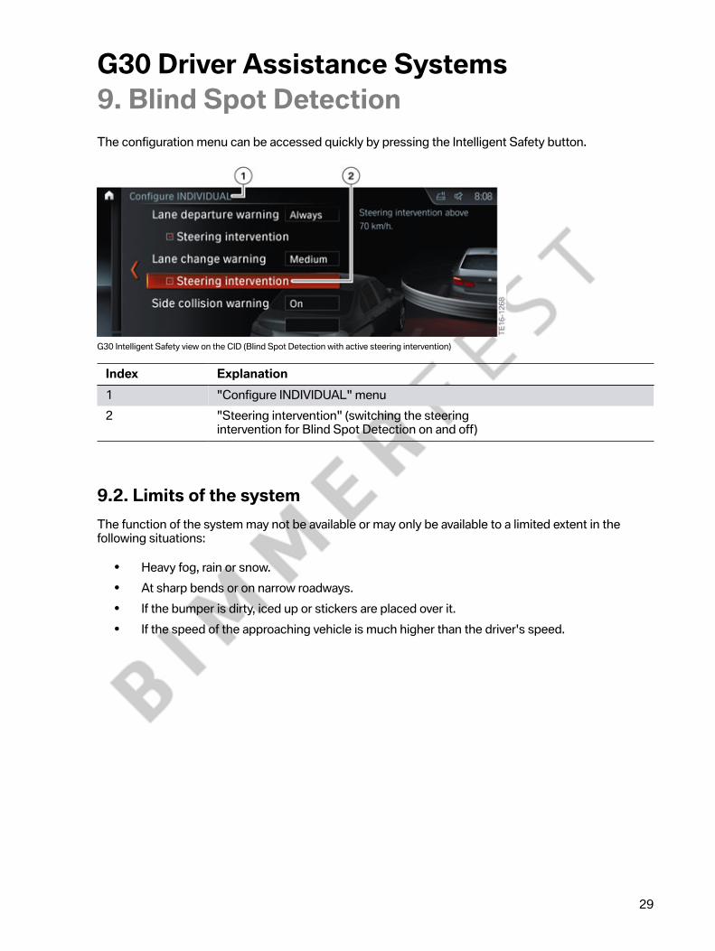
The�configuration�menu�can�be�accessed�quickly�by�pressing�the�Intelligent�Safety�button.
G30�Intelligent�Safety�view�on�the�CID�(Blind�Spot�Detection�with�active�steering�intervention)
Index Explanation1 "Configure�INDIVIDUAL"�menu2 "Steering�intervention"�(switching�the�steering
intervention�for�Blind�Spot�Detection�on�and�off)
9.2.�Limits�of�the�systemThe�function�of�the�system�may�not�be�available�or�may�only�be�available�to�a�limited�extent�in�thefollowing�situations:
• Heavy�fog,�rain�or�snow.• At�sharp�bends�or�on�narrow�roadways.• If�the�bumper�is�dirty,�iced�up�or�stickers�are�placed�over�it.• If�the�speed�of�the�approaching�vehicle�is�much�higher�than�the�driver's�speed.

G30�Driver�Assistance�Systems10.�Side�Collision�Avoidance
30
The�Side�Collision�Avoidance�is�part�of�the�Active�Lane�Keeping�Assistant�with�Side�CollisionAvoidance.�The�Active�Lane�Keeping�Assistant�with�Side�Collision�Avoidance�is�part�of�the�scopeof�supply�of�the�Active�Driving�Assistant�Plus,�optional�equipment�(OE�5AT).�The�Side�CollisionAvoidance�is�not�available�separately.
The�Side�Collision�Avoidance�assists�the�driver�in�avoiding�a�potential�side�collision.
Four�radar�sensors�monitor�the�area�next�to�the�vehicle�and�function�regardless�of�the�lightingconditions�and�largely�irrespective�of�the�weather�conditions.
G30�Vehicle�detection�using�radar�sensors�(Side�Collision�Avoidance)
If�there�is�a�risk�of�a�collision,�the�corresponding�indicator�flashes�(depending�on�which�side�the�riskrelates�to,�left�or�right)�in�the�exterior�mirror�with�high�intensity�and�the�steering�wheel�starts�to�vibrate.
G30�Signal�unit�(LED)�in�mirror�glass

G30�Driver�Assistance�Systems10.�Side�Collision�Avoidance
31
An�active�steering�intervention�is�then�initiated,�which�assists�the�driver�in�moving�his�vehicle�back�to�asafe�area�within�his�own�lane.
G30�Side�Collision�Avoidance�with�active�steering�intervention�in�the�event�of�a�potential�side�collision
The�steering�intervention�is�initiated�within�a�speed�range�of�between�43�and�130�mph�(70 km/h�and210 km/h).
The�active�steering�intervention�can�be�felt�on�the�steering�wheel,�but�can�be�manually�overridden�bythe�driver�at�any�time.
Radar�sensors
The�rear�radar�sensors�are�Blind�Spot�Detection�(SWW)�sensors.
G30�Blind�Spot�Detection�(SWW)�(radar�sensors)

G30�Driver�Assistance�Systems10.�Side�Collision�Avoidance
32
Two�additional�radar�sensors�are�used�for�the�front�Side�Collision�Avoidance.
G30�Side�Collision�Avoidance�(radar�sensors)
Functional�prerequisites
A�prerequisite�for�the�activation�of�the�Side�Collision�Avoidance�with�steering�intervention�is�that�thelane�markings�must�be�detected�by�the�KAFAS�stereo�camera.
If�the�lane�markings�are�not�detected�or�if�the�driver�is�driving�within�the�speed�range�of�18�to�43�mph(30 to�70 km/h),�only�the�reduced�Side�Collision�Avoidance�is�active.�The�warning�functions�in�the�formof�the�flashing�indicator�in�the�exterior�mirror�and�the�vibration�of�the�steering�wheel�continue�to�beimplemented.
With�the�reduced�Side�Collision�Avoidance�there�is�no�active�lateral�guidance�of�the�vehicle.�In�thiscase�the�driver�is�only�warned�by�a�single�steering�wheel�pulse�on�the�opposite�side�of�the�wheel�to�thedanger.
The�Side�Collision�Avoidance�can�be�switched�on�and�off�via�the�iDrive�menu�by�making�the�followingselection�via�the�controller:
• "My�Vehicle"• "Vehicle�settings"• "Intelligent�Safety"• "Side�Collision�Avoidance"
The�configuration�menu�can�be�accessed�quickly�by�pressing�the�Intelligent�Safety�button.

G30�Driver�Assistance�Systems10.�Side�Collision�Avoidance
33
G30�Intelligent�Safety�view�on�the�CID�(Side�Collision�Avoidance)
Index Explanation1 "Configure�INDIVIDUAL"�menu2 "Side�Collision�Avoidance"3 "Side�Collision�Avoidance"�(switching�the�side�collision
warning�with�steering�intervention�on�and�off)
It�is�not�possible�to�switch�off�the�steering�intervention�for�the�Side�Collision�Avoidance�separately.
The�Side�Collision�Avoidance�automatically�activates�itself�again�after�the�vehicle�moves�off�if�thefunction�was�switched�on�at�the�time�of�the�last�engine�shutdown.
10.1.�Limits�of�the�systemThe�function�of�the�system�may�not�be�available�or�may�only�be�available�to�a�limited�extent�in�thefollowing�situations.
• Heavy�fog,�rain�or�snow.• At�sharp�bends�or�on�narrow�roadways.• If�the�bumper�is�dirty,�iced�up�or�stickers�are�placed�over�it.• If�driving�at�close�proximity�to�a�vehicle�driving�ahead.• If�the�speed�of�the�approaching�vehicle�is�much�higher�than�the�driver's�speed.

G30�Driver�Assistance�Systems11.�Intersection�Warning
34
Intersections�are�some�of�the�most�likely�points�for�accidents�in�urban�traffic.�Statistics�tell�us�thatapproximately�one�accident�in�three,�with�injury�to�persons,�occurs�at�an�intersection.�Accidents�herecan�largely�be�attributed�to�distraction�or�poor�estimation�by�the�drivers.
The�Intersection�Warning�is�installed�for�the�first�time�in�the�G30�and�can�make�a�major�contribution�tosafety.
The�driver�is�warned�both�visually�and�audibly�in�the�event�of�a�risk�of�a�collision�with�crossing�traffic.This�can�significantly�reduce�the�likelihood�of�an�accident�or�even�the�severity�of�an�accident�atintersections.
Intersection�Warning�is�an�integral�part�of�the�Active�Driving�Assistant�Plus,�optional�equipment(OE�5AT).
11.1.�Functional�principleIntersection�Warning�is�able�to�detect�an�impending�collision�with�crossing�traffic�in�good�time�and�sosuch�collisions�can�possibly�be�prevented�by�this.
The�KAFAS�stereo�camera�and�the�front�radar�sensor�(ACC�radar�sensor)�monitor�the�trafficconditions.�The�information�obtained�from�these�sources�forms�the�basis�for�the�system.�The�sensorsdetect�the�distance�from�other�traffic�and�its�speed�and�direction�of�movement.�The�speed�of�the�car�isalso�determined.
G30�Intersection�Warning
G30�Driver�Assistance�Systems11.�Intersection�Warning
35
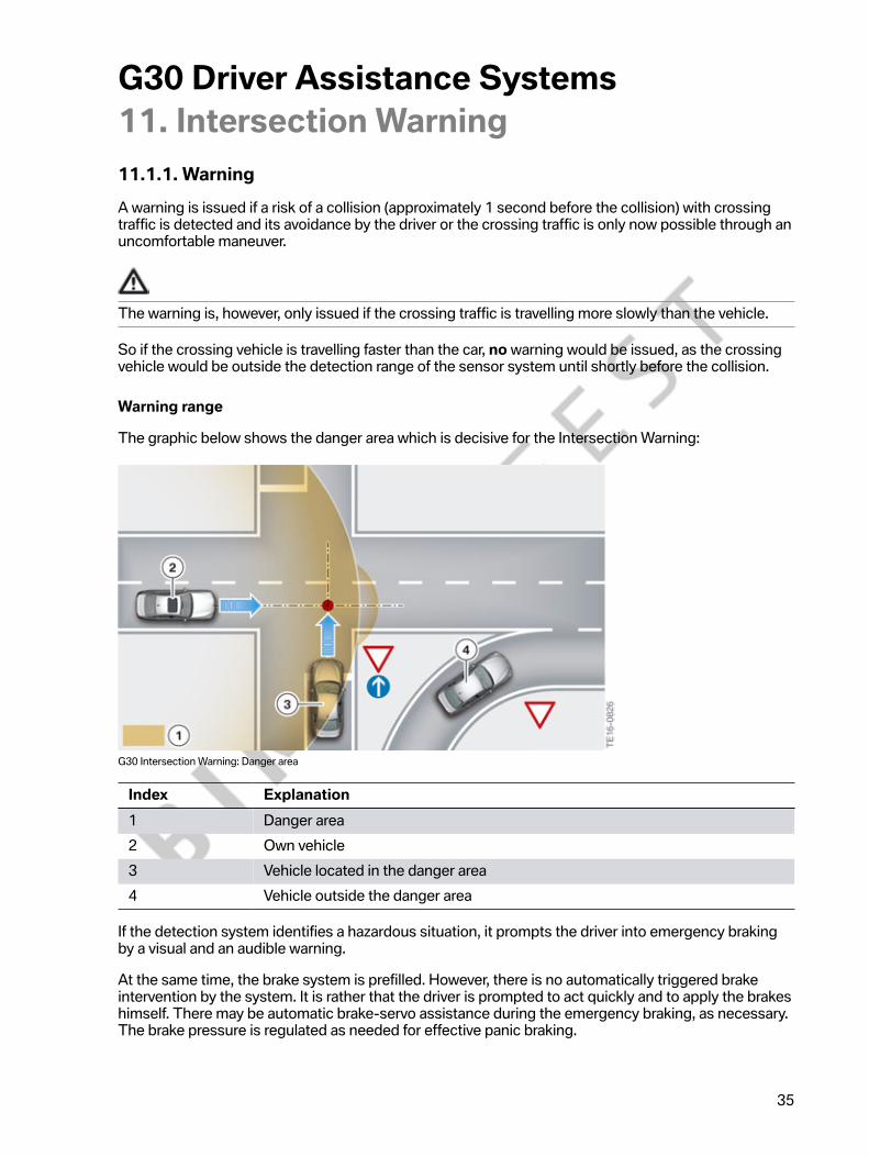
11.1.1.�WarningA�warning�is�issued�if�a�risk�of�a�collision�(approximately 1 second�before�the�collision)�with�crossingtraffic�is�detected�and�its�avoidance�by�the�driver�or�the�crossing�traffic�is�only�now�possible�through�anuncomfortable�maneuver.
The�warning�is,�however,�only�issued�if�the�crossing�traffic�is�travelling�more�slowly�than�the�vehicle.
So�if�the�crossing�vehicle�is�travelling�faster�than�the�car,�no�warning�would�be�issued,�as�the�crossingvehicle�would�be�outside�the�detection�range�of�the�sensor�system�until�shortly�before�the�collision.
Warning�range
The�graphic�below�shows�the�danger�area�which�is�decisive�for�the�Intersection�Warning:
G30�Intersection�Warning:�Danger�area
Index Explanation1 Danger�area2 Own�vehicle3 Vehicle�located�in�the�danger�area4 Vehicle�outside�the�danger�area
If�the�detection�system�identifies�a�hazardous�situation,�it�prompts�the�driver�into�emergency�brakingby�a�visual�and�an�audible�warning.
At�the�same�time,�the�brake�system�is�prefilled.�However,�there�is�no�automatically�triggered�brakeintervention�by�the�system.�It�is�rather�that�the�driver�is�prompted�to�act�quickly�and�to�apply�the�brakeshimself.�There�may�be�automatic�brake-servo�assistance�during�the�emergency�braking,�as�necessary.The�brake�pressure�is�regulated�as�needed�for�effective�panic�braking.

G30�Driver�Assistance�Systems11.�Intersection�Warning
36
Displays
The�visual�warning�is�given�by�the�following�warning�symbols:
Symbol ExplanationIntersection�Warning�symbol�(warning�of�vehicleapproaching�from�the�left)
Intersection�Warning�symbol�(warning�of�vehicleapproaching�from�the�right)
The�visual�warning�appears�in�the�KOMBI�instrument�cluster�or�Head‐Up�Display�if�the�vehicle�is�fittedwith�the�Head‐Up�Display�(OE 610).
G30�Intersection�Warning:�Warning�symbol
The�Intersection�Warning�is�active�in�the�speed�range�from�approximately�9�mph�(15 km/h)�toapproximately�40�mph�(65 km/h).
The�Intersection�Warning�is�also�switched�off�by�selecting�ALL�OFF.�There�is�no�separate�deactivationor�configuration�option�in�the�iDrive�menu�for�the�Intersection�Warning.
The�Intersection�Warning�system�does�not�relieve�the�driver�of�personal�responsibility�for�correctlyjudging�the�visibility�and�traffic�situation.�The�driver's�driving�style�should�be�adapted�to�the�trafficconditions.�The�driver�should�check�the�traffic�conditions,�and�react�accordingly�if�required.

G30�Driver�Assistance�Systems11.�Intersection�Warning
37
11.2.�Limits�of�the�systemThe�function�of�the�Intersection�Warning�may�be�restricted�because�of�system�limits�or�unfavorableconditions�in�the�following�situations,�for�example:
• If�there�are�other�objects�in�the�field�of�view�of�the�sensors�that�are�concealing�the�cross�traffic.• Heavy�fog,�rain�or�snow.• If�the�front�bumper�is�dirty�or�iced�up.• If�stickers�have�been�attached�near�the�radar�sensors�on�the�bumper.• If�the�speed�of�the�approaching�vehicle�is�very�high.• If�crossing�objects�are�moving�very�slowly.• If�it�is�almost�impossible�to�detect�the�crossing�traffic�because�of�the�way�the�road�runs�or
topographical�conditions,�for�example�in�tight�bends,�building�complexes�in�the�way�etc.
The�system�does�not�replace�the�personal�assessment�of�the�road�and�the�traffic�situation.The�Intersection�Warning�is�only�intended�to�assist�the�driver.�There�can�be�functional�limitationsbecause�of�system�restrictions�or�unfavorable�topographical�conditions.

G30�Driver�Assistance�Systems12.�Road�Sign�Recognition
38
The�Speed�Limit�Information�function�is�known�from�the�G12.�Current�top�speed�limitations�aredetected�by�the�Road�Sign�Recognition�system�and�displayed�in�the�instrument�cluster�or�the�Head‐UpDisplay�in�the�form�of�speed�limit�symbols.
Top�speed�limitation�symbol�shown�in�the�instrument�cluster
Index Explanation1 Road�Sign�Recognition�(example:�a�detected�top�speed�limitation�is�displayed)
Road�Sign�Recognition�(Speed�Limit�Information)�is�part�of�the�Active�Driving�Assistant,�optionalequipment�(OE�5AS),�in�the�G30.
The�system�does�not�relieve�the�driver�of�personal�responsibility�for�correctly�judging�the�visibility�andtraffic�situation.�The�driver�is�solely�responsible�for�the�vehicle�and�the�speed�at�which�it�is�driven.
12.1.�OperationThe�road�sign�detection�can�be�switched�on�and�off�via�the�iDrive�menu�by�making�the�followingselection�via�the�controller:
• "My�Vehicle"• "iDrive�settings"• "Displays"• "Instrument�panel"• Apply�desired�settings
G30�Driver�Assistance�Systems12.�Road�Sign�Recognition
39
12.2.�Limits�of�the�systemRoad�signs�for�top�speed�limitations�that�do�not�comply�with�the�legal�standard,�particularly�thosewithout�circular�frames,�are�not�always�detected.�The�same�also�applies�for�road�signs�which�are�fullyor�partially�covered�by�labels,�dirt�or�vegetation.�Long�distances�to�the�road�sign,�high�driving�speedsand�poor�weather�conditions,�particularly�at�night,�make�it�more�difficult�for�the�system�to�recognizeroad�signs�reliably.�To�ensure�the�current�top�speed�limitations�are�displayed�as�accurately�as�possible,the�data�of�the�navigation�road�map�should�be�up-to-date.
The�functionality�of�the�Road�Sign�Recognition�may�be�impaired�in�the�following�situations�and�thismay�lead�to�incorrect�information�being�displayed:
• Heavy�fog,�rain�or�snow.• If�signs�are�covered�by�objects.• If�driving�at�close�proximity�to�a�vehicle�driving�ahead.• Strong�light�in�the�camera�lens.• If�the�windscreen�in�front�of�the�interior�mirror�is�misted�over,�soiled�or�covered�by�stickers,�etc.• As�a�result�of�incorrect�detection�by�the�camera.• If�the�top�speed�limitations�stored�in�the�navigation�system�are�incorrect.• In�areas�not�covered�by�the�navigation�system.• In�the�event�of�deviations�from�the�navigation,�e.g.�due�to�modified�road�layouts.• When�overtaking�buses�or�trucks�with�speed�limit�stickers.• If�road�signs�do�not�correspond�to�the�standard.• When�calibrating�the�camera�immediately�after�vehicle�delivery.
The�system�does�not�replace�the�personal�assessment�of�the�traffic�situation.�Due�to�systemrestrictions�and�functional�limitations,�it�may�transpire�that�warnings�and�alerts�are�not�issued,�areissued�too�late�or�are�unwarranted.�The�Road�Sign�Recognition�supports�the�driver�and�does�notreplace�the�human�eye.
G30�Driver�Assistance�Systems13.�Proactive�Driving�Assistant
40
The�Proactive�Driving�Assistant�indicates�to�the�driver�the�ideal�time�to�lift�off�the�accelerator�pedal�fora�reduction�in�consumption.
Relevant�sections�of�road�are:
• Intersections• Bends• Crossroads• Roundabouts• Entrances�to�towns• Top�speed�limitations• Highway�exits
Operation�of�the�Proactive�Driving�Assistant�in�the�G30�requires�the�Active�Driving�Assistant�Plus,optional�equipment�(OE�5AT).
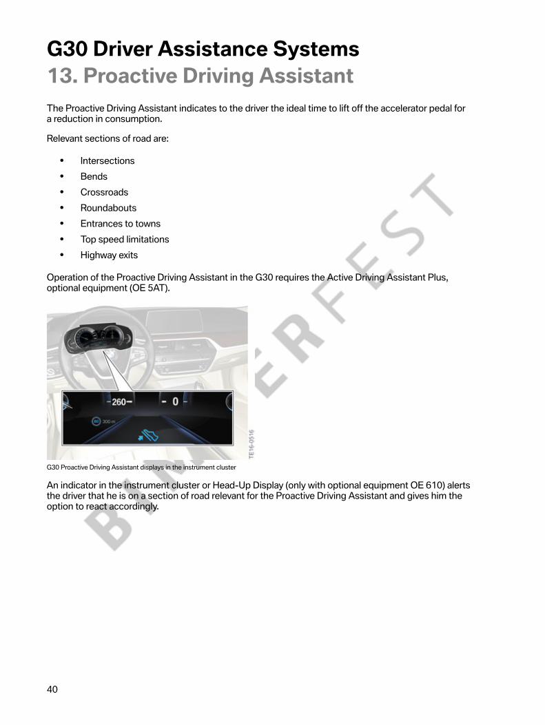
G30�Proactive�Driving�Assistant�displays�in�the�instrument�cluster
An�indicator�in�the�instrument�cluster�or�Head-Up�Display�(only�with�optional�equipment�OE 610)�alertsthe�driver�that�he�is�on�a�section�of�road�relevant�for�the�Proactive�Driving�Assistant�and�gives�him�theoption�to�react�accordingly.

G30�Driver�Assistance�Systems13.�Proactive�Driving�Assistant
41
13.1.�OperationTo�use�the�proactive�driving�assistant,�ECO�PRO�mode�or�ECO�PRO+�mode�must�be�activated�via�thedriving�experience�switch.
G30�Switch�block�with�driving�experience�switch
The�proactive�driving�assistant�can�be�switched�on�and�off�in�the�ECO�PRO�configuration�menu.
The�reliability�of�the�system�depends�on�having�the�most�current�and�accurate�navigation�data.
13.2.�Limits�of�the�systemThe�proactive�driving�assistant�is�not�available�in�the�following�situations:
• Speeds�below�31�mph�(50�km/h)• Temporary�and�variable�top�speed�limitation,�such�as�on�building�sites• Quality�of�navigation�data�insufficient• Cruise�control�active
Additional�information�may�be�found�in�the�“G12�Driver�Assistance�Systems”�reference�manual(section�12).
G30�Driver�Assistance�Systems14.�Fatigue�and�Focus�Alert
42
The�Fatigue�and�Focus�Alert�helps�to�avoid�accidents�caused�by�tiredness�on�long,�monotonousjourneys.�It�is�part�of�the�Active�Protection�equipment�(OE�5AL)�included�in�the�basic�equipment.
A�change�in�the�driver's�driving�behavior�is�perceived�by�the�Fatigue�and�Focus�Alert.�In�the�eventof�increasing�inattentiveness�or�if�the�driver�is�tired,�the�Fatigue�and�Focus�Alert�shows�a�displayrecommending�that�the�driver�take�a�break�as�a�Check�Control�message�in�the�Central�InformationDisplay�(CID).
The�Fatigue�and�Focus�Alert�is�automatically�active�after�each�engine�start�from�a�speed�of�roughly43�mph�(70 km/h).
14.1.�OperationThe�Fatigue�and�Focus�Alert�can�be�switched�on�and�off�via�the�iDrive�menu.�The�driver�can�also�setthe�level�of�sensitivity�in�this�menu�by�making�the�following�selection�via�the�controller:
• "My�Vehicle"• "Vehicle�settings"• "Fatigue�and�Focus�Alert"• Select�desired�settings
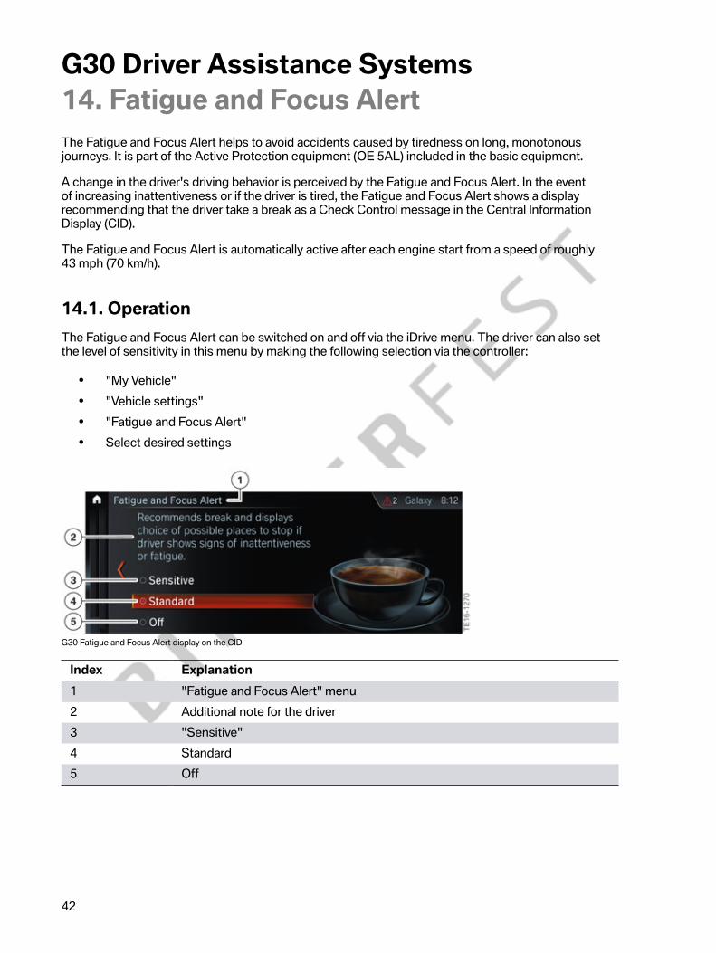
G30�Fatigue�and�Focus�Alert�display�on�the�CID
Index Explanation1 "Fatigue�and�Focus�Alert"�menu2 Additional�note�for�the�driver3 "Sensitive"4 Standard5 Off

G30�Driver�Assistance�Systems14.�Fatigue�and�Focus�Alert
43
The�settings�for�the�Fatigue�and�Focus�Alert�has�the�following�differences:
Selected�setting ExplanationSensitive The�break�recommendation�is�issued�earlier
(significantly�more�sensitive�or,�in�other�words,earlier�output�compared�to�the�"Standard"setting).
Standard The�break�recommendation�is�issued�with�adefined�value�(in�the�same�way�as�for�BMWmodels�up�to�now).
Off A�break�recommendation�is�not�issued.
14.2.�Limits�of�the�systemThe�functionality�may�be�impaired�in�the�following�situations�and�no�warning�or�an�incorrect�warningmay�be�issued:
• If�the�clock�is�set�incorrectly.• If�the�speed�is�predominantly�below�approximately�43�mph�(70 km/h).• If�the�driver�adopts�a�sporty�driving�style,�for�example�rapid�acceleration�or�fast�cornering.• In�active�driving�situations,�for�example�frequent�lane�changes.• Poor�road�condition.• Strong�crosswind.
The�system�does�not�relieve�the�driver�of�personal�responsibility�for�correctly�judging�his�physicalcondition.�Increasing�inattentiveness�or�fatigue�may�not�be�detected�at�all�or�in�time.

G30�Driver�Assistance�Systems15.�Night�Vision
44
In�the�G30,�the�Night�Vision�system�is�available�in�the�form�of�BMW�Night�Vision�with�person�andanimal�detection,�optional�equipment�(OE�6UK).
Night�Vision�detects�people�and�animals�in�optimum�conditions�at�night�up�to�a�distance�ofapproximately�330�ft�(100 m)�away�and�therefore�assists�the�driver,�especially�on�dark�and�difficultstretches�of�road,�such�as�when�driving�on�single-lane�roads�with�adjacent�woods.
In�potentially�dangerous�situations,�the�system�warns�the�driver�of�people�and�animals�on�the�road.
The�Night�Vision�camera�integrated�in�the�BMW�radiator�grille�records�the�area�in�front�of�the�vehicleand�sends�the�data�to�the�Night�Vision�Electronics�(NVE).
G30�Night�Vision�camera
The�image�data�is�analyzed�by�the�Night�Vision�Electronics�control�unit�and�the�corresponding�imageinformation�is�sent�to�the�head�unit�via�the�Color�Video�Blanking�Signal.
G30�Night�Vision�Electronics�(NVE)�control�unit

G30�Driver�Assistance�Systems15.�Night�Vision
45
Hot�objects�with�outlines�that�resemble�people�or�animals�are�detected�by�the�system�and�can�bedisplayed�on�the�Central�Information�Display�if�necessary.
G30�Night�Vision�detection�range
Index Explanation1 Night�Vision�camera�detection�range2 Night�Vision�camera�image�showing�detected�person
(display�on�the�Central�Information�Display)3 Night�Vision�camera�image�showing�detected�animals
(display�on�the�Central�Information�Display)
Object�detection�range
• Person�recognition:�up�to�approximately�330�ft�(100 m)• Recognition�of�large�animals:�up�to�approximately�500�ft�(150 m)• Recognition�of�medium-sized�animals:�up�to�approximately�230�ft�(70 m)
Warning�levels
Night�Vision�detects�people�and�determines�their�position�and�distance�from�the�vehicle.�Taking�intoaccount�the�driving�speed�and�steering�angle,�the�system�calculates�whether�there�is�a�potential�riskand�displays�a�warning�sign�(early�warning)�in�the�instrument�cluster�and�in�the�Head-Up�Display,�ifpresent.
In�critical�situations�a�warning�signal�also�sounds�(acute�warning).�The�warning�threshold�values�arealso�dependent�on�whether�the�person�or�the�animal�is�moving�or�standing�still.

G30�Driver�Assistance�Systems15.�Night�Vision
46
The�table�below�shows�an�overview�of�the�symbols�with�their�meanings:
Symbols ExplanationEarly�warning�(person�on�the�roadway)
Early�warning�(person�crossing�the�roadway)
Acute�warning�when�a�person�is�detected
Early�warning�when�an�animal�is�detected
Acute�warning�when�an�animal�is�detected

G30�Driver�Assistance�Systems15.�Night�Vision
47
15.1.�OperationNight�Vision�is�automatically�switched�on�every�time�the�vehicle�drives�off�when�it�is�dark.�The�warningfunctions�are�therefore�issued�irrespective�of�the�view�on�the�Central�Information�Display.�The�drivercan�switch�the�Night�Vision�camera�display�on�the�Central�Information�Display�on�and�off�by�pressingthe�Night�Vision�button�in�the�light�operating�unit.
It�is�also�possible�to�set�the�brightness�and�contrast�of�the�Night�Vision�display�via�the�iDrive.
G30�Button�for�thermal�imaging�camera/Night�Vision
Index Explanation1 Night�Vision�button

G30�Driver�Assistance�Systems15.�Night�Vision
48
15.2.�Limits�of�the�systemThe�functionality�may�be�impaired�in�the�following�situations�and�no�warning�or�an�incorrect�warningmay�be�issued:
• On�steep�summits�or�dips�and�tight�bends.• If�the�camera�is�dirty�or�the�protective�screen�is�damaged.• Heavy�fog,�rain�or�snow.• If�the�outside�temperatures�are�very�high.
The�person�and�animal�recognition�may�also�be�impaired�or�may�not�issue�the�usual�warnings.This�can�occur�in�the�following�cases:
• If�the�person�or�animal�is�fully�or�partially�hidden,�particularly�the�head.• If�the�person�is�not�in�an�upright�position,�e.g.�if�they�are�lying�down.• If�a�bike�has�non-conventional�wheels,�e.g.�recumbent�bicycle.• If�the�system�has�been�affected�mechanically,�e.g.�after�an�accident.
In�certain�cases�small�animals�may�be�entirely�visible�on�the�Central�Information�Display,�but�maynot�be�identified�by�the�object�detection.�As�a�consequence,�a�warning�is�also�not�issued.
The�system�does�not�relieve�the�driver�of�personal�responsibility�for�correctly�judging�the�visibility�andtraffic�situation.�The�driver�is�solely�responsible�for�the�vehicle�and�the�speed�at�which�it�is�driven.

G30�Driver�Assistance�Systems16.�Cameras
49
The�camera�systems�provide�support�for�parking,�maneuvering�and�for�complex�exits�andintersections.
The�range�of�camera�systems�offered�has�changed�completely�with�the�G30.�With�the�exception�of�therear�view�camera,�the�systems�are�no�longer�available�as�individual�items�of�optional�equipment.
The�new�range�strategy�now�looks�like�this:
• The�rear�view�camera�is�available�separately�as�the�rear�view�camera,�optional�equipment(OE�3AG).
• Surround�View�is�offered�in�conjunction�with�the�Parking�Assistant�Plus,�optional�equipment(OE 5DN).�The�Surround�View�function�with�Top�View,�Panorama�View�and�3D�View�provides360°�visibility�around�the�vehicle.
• The�Remote�3D�view�(Remote�360°)�is�presented�for�the�first�time�in�conjunction�with�theParking�Assistant�Plus,�optional�equipment�(OE 5DN).�This�function�allows�the�customer�todisplay�images�of�his�parked�vehicle�on�a�mobile�device�(such�as�a�smartphone).
16.1.�Surround�ViewSurround�View�shows�the�vehicle�surroundings�and�displays�them�in�TOP�View�and�3D�View�on�theCentral�Information�Display.
The�system�comprises�the�front�camera,�the�two�cameras�integrated�in�the�exterior�mirrors,�the�rearview�camera�(RFK)�and�the�Top�Rear�Side�View�Camera�(TRSVC)�control�unit.�The�TRSVC�may�bereferred�to�as�ICAM2�in�technical�systems.
The�images�from�the�four�cameras�are�combined�into�a�panoramic�view�around�the�vehicle�fromdifferent�angles�using�3D�computer�graphics.
The�driver�can�choose�from�preset�views�or�can�freely�select�the�view�(for�example,�car�washentrances).
In�addition,�assistance�functions�such�as�guidance�lines�can�be�shown�on�the�Central�InformationDisplay.
The�following�camera�angles�can�be�displayed:
• Automatic�camera�angle• Side�view• Front�camera• Panorama�view• Rear�view�camera• Moving�camera�angle

G30�Driver�Assistance�Systems16.�Cameras
50
16.1.1.�Automatic�camera�angleThe�system�automatically�shows�the�most�appropriate�camera�angle�depending�on�the�drivingsituation,�thus�providing�the�driver�with�optimum�assistance�when�parking�and�maneuvering.�Theautomatic�camera�angle�shows�a�steering-dependent�view�and�takes�into�account�the�respectivedirection�of�travel�and�the�distance�information�from�the�Park�Distance�Control�(PDC).
As�soon�as�obstacles�are�detected,�the�view�changes�to�a�fixed�display�of�the�area�in�front�of�or�behindthe�vehicle,�or�changes�to�the�corresponding�side�view�if�required.
16.1.2.�Side�viewThis�view�helps�the�driver�to�position�the�vehicle�next�to�the�curb�or�other�obstacles�at�the�sideof�the�vehicle�by�displaying�the�side�surroundings.�The�side�view�is�from�the�rear�to�the�front�andautomatically�focuses�on�potential�obstacles�if�there�is�a�collision�risk.
Both�the�left�and�right�sides�of�the�vehicle�are�recorded.
16.1.3.�Front�cameraThe�front�camera�supports�the�driver�when�parking�and�maneuvering.�The�area�in�front�of�the�vehicleis�recorded�by�the�front�camera�and�shown�on�the�Central�Information�Display.�The�front�camera�viewcannot�be�selected�separately.�The�driver�must�select�the�"Auto"�camera�angle�to�view�it�or�if�desired,switch�on�the�"Panorama�View"�function.
16.1.4.�Panorama�ViewPanorama�View�enables�the�driver�to�see�the�cross�traffic�at�blind�exits�and�intersections�beforeproceeding�and�provides�the�driver�with�optimum�assistance�in�this�situation.�Road�users�that�arehidden�by�obstacles�to�the�side�of�the�vehicle�are�sometimes�only�seen�by�the�driver�very�late�or�not�atall.�To�improve�the�view,�the�front�and�rear�view�cameras�record�the�lateral�roadway�area.�Depending�onwhich�drive�position�is�engaged,�the�front�or�rear�view�camera�can�be�activated.

G30�Driver�Assistance�Systems16.�Cameras
51
G30�Panorama�View�on�the�CID
Yellow�lines�in�the�screen�display�mark�the�front�and�rear�ends�of�the�vehicle.�The�camera�image�isbadly�distorted�in�some�areas�and�is�therefore�not�suitable�for�estimating�distances.
The�function�can�be�activated�using�the�Panorama�View�button.�Press�the�button�again�to�deactivatethe�function.�The�Panorama�View�function�is�automatically�deactivated�at�speeds�above�approximately9�mph�(15 km/h).
Panorama�View�(GPS-based)
GPS-supported,�automatic�activation�of�the�Panorama�View�function�has�been�implementedin�the�G30.
G30�Automatic�switch�on�at�a�set�activation�point
Positions�at�which�the�Panorama�View�should�switch�itself�on�automatically�can�be�saved�as�activationpoints�provided�that�a�GPS�signal�is�received.�A�maximum�of�ten�activation�points�can�be�saved�for�thefront�camera.

G30�Driver�Assistance�Systems16.�Cameras
52
To�save�the�activation�points,�the�driver�must�proceed�as�follows:
• Stop�after�reaching�the�place�where�the�Panorama�View�should�switch�itself�on�automatically.• Press�the�Panorama�View�button�and�then�tilt�the�controller�to�the�left.• Then�select�"Add�activation�point"�(the�current�position�is�displayed)�and�confirm�by�selecting
"Add�activation�point."
G30�Setting�activation�points
Index Explanation1 "Add�activation�point"
If�possible,�the�activation�points�are�saved�with�the�town/city�and�street�or�with�the�GPS�coordinates.The�direction�of�travel�is�also�saved�in�conjunction�with�the�activation�point.
The�driver�can�display�the�saved�activation�points�on�the�Central�Information�Display.

G30�Driver�Assistance�Systems16.�Cameras
53
G30�Displaying�activation�points
Index Explanation1 "Show�activation�points"
The�use�of�activation�points�can�be�switched�on�and�off�via�iDrive.
G30�Panorama�View�activation�menu�on�the�CID
Index Explanation1 "Parking"�menu2 "Panorama�View,�GPS-based"

54
G30 Driver Assistance Systems16. Cameras16.1.5. Rear view cameraThe rear view camera supports the driver when parking and maneuvering. The area behind the vehicleis recorded by the rear view camera and shown on the Central Information Display.
G30 Rear view camera image in the CID
16.1.6. Moving camera angleWhen the moving camera angle is selected, a circular trajectory is shown around the vehicle on theCentral Information Display. Predetermined angles can be selected on the circular trajectory by turningthe controller or using the touch function.
In vehicles with the Gesture Control, optional equipment (OE 6U8), the moving camera angle can alsobe controlled in this way.
The current angle is identified by a camera symbol. Depending on the view, the surroundings of thevehicle or a partial area of the surroundings are shown on the Central Information Display.

G30�Driver�Assistance�Systems16.�Cameras
55
G30�Exterior�camera�view�(moving�camera�angle)�on�the�CID
To�leave�this�view,�tilt�the�controller�to�the�side,�press�it�or�touch�the�highlighted�camera�symbol�via�thetouch�screen.
If�Gesture�Control�is�being�used,�the�gesture�symbol�is�shown�on�the�right�half�of�the�CentralInformation�Display�screen.
Rotating�the�camera�view�using�Gesture�Control

G30�Driver�Assistance�Systems16.�Cameras
56
16.2.�Overview�of�exterior�camera�operating�menuOnce�the�camera�systems�have�been�activated�successfully,�the�driver�has�the�option�of�selecting�theappropriate�view�or�camera�via�iDrive.
G30�Switch�block�with�Panorama�View�button
Index Explanation1 Parking�assistance�button2 Panorama�View�button
The�camera�systems�can�be�activated�(depending�on�the�vehicle�equipment)�as�follows:
• Manually�by�pressing�the�parking�assistance�button�or�the�camera�button�(Panorama�View).• By�engaging�drive�position�"R".• By�engaging�reverse�gear�(on�vehicles�with�a�manual�gearbox).• Automatically�via�the�"Auto�PDC"�function.• Automatically�via�the�GPS-supported�automatic�activation�of�the�Panorama�View�function,
provided�that�activation�points�have�been�saved.

G30�Driver�Assistance�Systems16.�Cameras
57
G30�Exterior�cameras�view�(camera�angles)�on�the�CID
Index Explanation1 Toolbar2 Selection�window3 Side�view4 Automatic�camera�angle5 Rear�view�camera6 Moving�camera�angle7 Camera�image
Other�settings�and�options�can�be�found�in�the�toolbar,�depending�on�the�vehicle�equipment.�Thus,for�example,�the�driver�can�switch�the�parking�assistance�lines,�the�obstacle�marking�etc.�on�and�off,�oralso�make�adjustments�to�the�image�brightness�and�contrast.�The�driver�can�also�activate�or�deactivatethe�assistance�functions�here�such�as�the�car�wash�view,�for�instance.
16.3.�Assistant�functionThe�following�assistance�functions�are�available:
• Car�wash�view• Side�protection• Door�opening�angle

G30�Driver�Assistance�Systems16.�Cameras
58
16.3.1.�Car�wash�viewThe�car�wash�view�assists�the�driver�when�entering�a�car�wash.�When�the�car�wash�view�is�selected,immediately�before�entering�the�car�wash,�a�bird's�eye�view�is�displayed�on�the�Central�InformationDisplay.�To�enable�the�driver�to�align�the�vehicle�more�easily,�the�vehicle's�tire�tracks�are�shown�on�thedisplay.
The�car�wash�view�can�be�activated�via�the�iDrive�in�the�toolbar�under�the�"Car�wash"�menu�item.
G30�PDC�car�wash�view�on�the�CID
Index Explanation1 "Car�wash"

G30�Driver�Assistance�Systems16.�Cameras
59
16.3.2.�Side�protectionThe�side�protection�warns�against�obstacles�at�the�side�of�the�vehicle�and�thus�supports�the�driverwhen�parking�and�maneuvering.
To�protect�the�sides�of�the�vehicle�from�collisions�with�obstacles,�additional�obstacle�markings�areshown�to�the�side�of�the�vehicle�on�the�Central�Information�Display,�if�necessary.
G30�Side�protection�view�(additional�obstacle�markings)
More�information�on�the�operation�of�the�side�protection�function�can�be�found�in�section�17.4.

G30�Driver�Assistance�Systems16.�Cameras
60
16.3.3.�Door�opening�angleWhen�the�vehicle�is�stopped�and�the�selector�lever�position�"P"�is�engaged,�the�maximum�openingangle�of�the�doors�is�displayed�on�the�Central�Information�Display.
If�there�is�an�obstacle�near�the�door�and�it�is�detected�by�the�side�protection,�this�is�marked�on�theCentral�Information�Display.�The�obstacle�marking�display�only�points�out�objects�in�the�area�ofthe�door.�It�is�not�possible�for�a�view�from�the�camera�systems�to�be�displayed,�as�the�door�area�issimulated.�Therefore,�the�driver�is�only�informed�that�there�is�an�object�at�the�side�of�the�vehicle;�it�isnot�certain�that�the�door�will�definitely�collide�with�the�identified�object.�The�driver�must�judge�this�forhimself.
G30�Door�opening�angle�view�on�the�CID
The�"Parking�assistance�lines"�and�"Obstacle�marking"�features�already�used�in�other�BMW�modelscan�also�be�activated�and�deactivated�via�the�iDrive�in�the�toolbar�under�the�relevant�menu�items.
The�camera�systems�do�not�relieve�the�driver�of�personal�responsibility�for�correctly�judging�the�trafficsituation.�There�is�still�a�risk�of�an�accident.�The�driver's�driving�style�should�be�adapted�to�the�trafficconditions.�The�driver�should�check�the�traffic�conditions�and�the�vehicle's�surroundings�by�lookingaround�and�react�accordingly�if�required.
16.4.�Remote�3D�ViewThe�Remote 3D�View�(Remote 360°)�is�provided�for�the�first�time�on�the�G30.�This�function�allows�thecustomer�to�display�images�of�his�parked�vehicle�on�a�mobile�device�(such�as�a�smartphone).
The�user�can�send�a�remote�request�to�the�parked�vehicle�through�his�device.�The�vehicle�takesimages�of�its�surroundings�and�sends�these�to�the�device�where�an�app�generates�a�3D�view.The�view�can�be�adjusted�by�gesture,�as�in�the�vehicle.
The�customer�thus�has�the�capability�of�viewing�his�vehicle's�surroundings�at�any�time.
Examples:
• What�does�it�look�like�around�my�vehicle?• Who�or�what�is�near�my�vehicle?
Remote 3D�View�is�part�of�the�Parking�Assistant�Plus�optional�equipment�(OE 5DN).

G30�Driver�Assistance�Systems16.�Cameras
61
16.4.1.�Functional�principleSurround�View�is�a�prerequisite�for�Remote�3D�View�(Remote 360°)�as�it�includes�the�Top�View 3Dfunction.�This�means�that�the�already�familiar�cameras�are�used.
The�function�is�sold�via�the�Remote�Services�standard�equipment�(6AP).
The�Remote�Services,�standard�equipment�(OE�6AP),�contains�a�number�of�functions�that�are�activefor�the�lifetime�of�the�vehicle.�Remote�3D�View�is,�however,�an�exception.�The�function�is�active�for2 years�following�activation.�The�service�expires�after�2 years.�In�this�event,�the�customer�is�notified�bytext�and�email�2�weeks�before�expiry�of�the�Remote�3D�View�service.
When�the�service�has�expired,�the�customer�has�the�option�of�activating�or�purchasing�the�function�fora�further�two�years�through�the�ConnectedDrive�Shop.�Availability�of�the�function�can�be�extended�asmany�times�as�desired�via�the�ConnectedDrive�Shop.
Application:
The�customer�should�like�to�have�an�image�of�the�area�around�his�parked�vehicle.
G30�Remote�3D�View
1 He�sends�a�request�to�the�BMW�back�end�via�the�BMW�Connected�App�(Remote 3D�View)�on�hissmartphone.
2 Following�verification�of�the�data,�the�BMW�back�end�passes�the�request�on�to�the�appropriatevehicle.�The�vehicle�then�takes�four�separate�Surround�View�images�using�the�externalcameras.�These�are�then�sent�in�the�Top�Rear�Side�View�Camera�control�unit�to�the�TelematicCommunication�Box�(TCB)�and�temporarily�buffered.

G30�Driver�Assistance�Systems16.�Cameras
62
G30�Remote�3D�View:�Surround�view�images
3 The�images�are�then�sent�by�the�vehicle�through�the�Telematic�Communication�Box�(TCB)�to�theBMW�back�end.
4 The�BMW�back�end�sends�the�image�data�and�a�matching�encryption�code�to�the�customer'ssmartphone.�Once�the�data�has�been�sent�to�the�smartphone,�it�is�deleted�from�the�BMW�backend.�The�image�data�received�is�merged�to�form�a�360°�all-round�view�in�the�smartphone.
G30�Remote�3D�View:�view�in�the�smartphone
The�3D�optical�display�appears�once�the�smartphone�has�received�all�four�images.

G30�Driver�Assistance�Systems16.�Cameras
63
Availability
The�system�includes�a�function�detecting�any�border�crossing�or�the�country�in�which�the�vehicle�islocated�in�order�to�allow�a�country-specific�release�and�configuration�of�the�Remote�3D�View�functionwhile�at�the�same�time�taking�account�of�local�laws�which�might�possibly�prohibit�the�use�of�thisfunction.�The�function�may�be�automatically�deactivated,�as�appropriate.
The�driver�also�has�the�possibility�of�activating�or�deactivating�the�function�itself�via�the�iDrive�(if�thefunction�is�supported�in�the�country�in�which�the�vehicle�is�located).
The�new�status�is�sent�to�the�BMW�back�end�after�every�change�to�the�setting�(to�Remote�3D�Viewdeactivated,�for�example).�The�BMW�back�end�stores�the�status�permanently�and�releases�or�inhibitsthe�function�calls�as�appropriate�on�the�basis�of�this.
16.5.�System�components
16.5.1.�Front�cameraThe�front�camera�is�installed�in�the�center�between�the�two�front�ornamental�grilles�on�the�G30.
G30�Front�camera

G30�Driver�Assistance�Systems16.�Cameras
64
16.5.2.�Top�view�cameraThe�two�are�installed�in�the�exterior�mirrors�on�the�G30.
G30�Exterior�mirror�camera,�left
Index Explanation1 Exterior�mirror�camera

G30�Driver�Assistance�Systems16.�Cameras
65
16.5.3.�Rear�view�cameraThe�rear�view�camera�supports�the�driver�when�parking�and�maneuvering.�The�area�behind�the�vehicleis�shown�on�the�Central�Information�Display.�Guidance�lines�integrated�in�the�image�provide�the�driverwith�additional�assistance�with�distances,�the�turning�circle�and�obstacle�markings,�if�required.
The�rear�view�camera�is�located�in�the�trunk�lid�handle�strip.
G30�Rear�view�camera
The�camera�has�been�revised�and�the�video�signals�are�now�transmitted�via�Ethernet�in�the�stand-alone�variant�too.�The�control�unit�remains�integrated�in�the�rear�view�camera�(RFK),�in�this�version.
System�wiring�diagram
The�system�wiring�diagram�below�shows�the�scope�of�the�rear�view�camera�(RFK)�optional�equipment(OE 3AG).

G30�Driver�Assistance�Systems16.�Cameras
66
G30�Rear�view�camera�RFK�(OE 3AG)�system�wiring�diagram

G30�Driver�Assistance�Systems16.�Cameras
67
Index Explanation1 Central�Information�Display�(CID)2 Body�Domain�Controller�(BDC)3 CAN�terminator4 Fuses�in�the�power�distribution�box,�rear�right5 Rear�view�camera�(RFK)6 Button�for�camera�activation7 Controller�(CON)8 Head�unit
16.5.4.�TRSVC�control�unitThe�exterior�cameras�record�the�area�around�the�vehicle�from�various�angles�and�send�this�informationto�the�TRSVC�control�unit�via�Ethernet.�The�video�signals�are�transmitted�from�the�TRSVC�control�unitto�the�head�unit�via�an�Ethernet�line.�The�head�unit�transmits�the�signals�to�the�Central�InformationDisplay�via�an�Automotive�Pixel�Link�line.
The�installation�location�of�the�TRSVC�control�unit�is�in�the�footwell�on�the�driver's�side.
G30�TRSVC�control�unit

G30�Driver�Assistance�Systems17.�Park�Distance�Control
68
The�Park�Distance�Control�(PDC),�optional�equipment�(OE�508),�assists�the�driver�when�maneuveringin�and�out�of�a�parking�space.�The�current�distance�from�an�obstruction�is�indicated�by�acoustic�signalsand�on�a�visual�display.
G30�Park�Distance�Control�PDC�view�in�the�CID
The�distance�from�an�obstruction�is�measured�by�four�ultrasonic�sensors�in�the�rear�bumper�panel�andfour�additional�ultrasonic�sensors�in�the�front�bumper�panel.
17.1.�System�components
G30�Park�Distance�Control�system�components

G30�Driver�Assistance�Systems17.�Park�Distance�Control
69
Index Explanation1 Ultrasonic�sensors�for�Park�Distance�Control,�front2 Central�Information�Display�(CID)3 Operating�unit4 Control�unit�for�Parking�Maneuvering�Assistant�(PMA)5 Ultrasonic�sensors,�Park�Distance�Control,�rear6 Head�Unit�High
Vehicles�that�do�not�have�the�Parking�Maneuvering�Assistant�but�do�have�the�Park�Distance�Controlhave�a�separate�control�unit,�which�is�recognized�as�the�PMA�control�unit�by�diagnosis�and�is�alsoreferred�to�by�this�name�in�the�bus�diagram.�In�other�words,�there�is�no�longer�a�difference�in�thenaming�of�the�PDC�and�PMA�control�unit�(there�are�however�differences�in�the�hardware�designbetween�the�control�units�and�the�software�is�adapted�to�the�equipment�specification).
G30�Control�unit�for�Parking�Maneuvering�Assistant�(PMA)
17.2.�Auto�PDCOn�the�G30,�Auto�PDC�is�activated�automatically�if�the�vehicle�is�approaching�an�object�at�a�speedbelow�approximately�3�mph�(5 km/h)�and�the�object�is�located�in�a�collision-critical�area.�The�Auto�PDCfunction�is�available�for�both�the�front�and�rear�of�the�vehicle.
The�automatic�switch-on�function�when�obstacles�are�detected�can�be�switched�on�and�off�via�iDrive.
Further�information�about�Auto�PDC�may�be�found�in�the�“G12�Driver�Assistance�Systems”�referencemanual�(section�16.2).

G30�Driver�Assistance�Systems17.�Park�Distance�Control
70
17.3.�Active�Park�Distance�ControlIn�G30�vehicles�with�the�Parking�Assistant,�optional�equipment�(OE�5DM),�or�Parking�Assistant�Plus,(OE�5DN)�optional�equipment,�the�Park�Distance�Control�function�has�been�extended�to�includethe�Active�Park�Distance�Control�function.�This�automatically�brakes�the�vehicle�to�a�stop�when�itis�travelling�at�walking�speed�(�<�approximately�4�mph�(6 km/h))�if�an�object�is�detected�behind�thevehicle.
The�Active�Park�Distance�Control�function�can�be�switched�on�and�off�via�iDrive.
The�system�does�not�relieve�the�driver�of�personal�responsibility�for�correctly�judging�the�trafficsituation.�The�driver�should�check�the�traffic�conditions�and�the�vehicle's�surroundings�by�lookingaround�and�react�accordingly�if�required.
Further�information�about�the�Active�Park�Distance�Control�function�may�be�found�in�the�“G12�DriverAssistance�Systems”�reference�manual�(section�16.3).
17.4.�Side�protectionThe�side�protection�warns�against�obstacles�at�the�side�of�the�vehicle�and�thus�supports�the�driverwhen�parking�and�maneuvering.
G30�Side�protection
Vehicles�with�the�Parking�Assistant,�optional�equipment�(OE�5DM),�have�side�protection.
Obstacles�detected�by�the�four�side�ultrasonic�sensors�integrated�in�the�bumpers�can�be�displayed�bythe�Park�Distance�Control�system.

G30�Driver�Assistance�Systems17.�Park�Distance�Control
71
Display�in�the�Central�Information�Display(CID)
Meaning
Colored�markings Warning�of�detected�obstaclesGrey�markings The�area�next�to�the�vehicle�has
not�yet�been�recordedNo�markings No�obstacles�have�been�detected
17.4.1.�Functional�principleFour�side�ultrasonic�sensors,�two�integrated�in�the�front�bumper�and�two�integrated�in�the�rear�bumper,measure�the�distance�to�an�obstruction.�Obstructions�detected�by�the�sensors�are�tracked�along�theside�of�the�vehicle�as�it�moves.�They�are�shown�on�the�Central�Information�Display�and,�in�situationswhere�a�collision�is�imminent,�an�acoustic�warning�also�sounds.
G30�Side�protection�view�on�the�CID
Obstructions�approaching�the�stationary�vehicle�are�not�taken�into�account,�as�in�this�case�the�systemcannot�evaluate�the�situation�unequivocally.�The�prerequisite�for�identifying�obstructions�is�that�the(driver's)�vehicle�is�moving.
The�distance�markings�shown�on�the�Central�Information�Display�are�displayed�for�approximately13 seconds�once�the�vehicle�has�stopped.�The�markings�are�only�shown�again�once�the�vehicle�startsmoving.

G30�Driver�Assistance�Systems17.�Park�Distance�Control
72
17.5.�OperationThe�Park�Distance�Control�system�is�enabled�in�the�following�situations:
• If�drive�position�R�reverse�gear�is�engaged�when�driving�readiness�is�switched�on.• If�the�parking�assistance�button�in�the�switch�block�next�to�the�controller�is�pressed
when�driving�readiness�is�switched�on.• Auto�PDC�is�activated�and�all�conditions�for�automatic�activation�are�met.
G30�switch�block�with�parking�assistance�button
Index Explanation1 Parking�assistance�button
Further�information�about�the�operating�concept�for�Auto�PDC,�the�Active�Park�Distance�Controlfunction�and�acoustic�signal�output�may�be�found�in�the�“G12�Driver�Assistance�Systems”�referencemanual�(section�16.5.1-16.5.3).
17.6.�Deactivation�criteriaSimilar�to�other�BMW�models,�the�deactivation�is�distance/speed-based.�The�switch-off�is�effectedafter�a�journey�of�approximately�164�ft�(50 m)�or�at�a�speed�over�6�mph�(10 km/h).
If�a�fault�develops,�a�Check�Control�message�"PDC�has�malfunctioned.�Have�system�checked."�isdisplayed�in�the�Central�Information�Display�(CID).�In�addition,�the�detection�range�of�the�sensors�isshown�shaded�in�the�Central�Information�Display�(CID).

G30�Driver�Assistance�Systems17.�Park�Distance�Control
73
17.7.�Limits�of�the�systemDue�to�the�physical�limits�during�the�ultrasonic�measurement,�obstructions�may�not�be�detected�by�thePark�Distance�Control�system.�Several�examples�of�this�are�shown�below:
• If�the�objects�are�thin�or�wedge-shaped.• When�the�objects�are�low.• When�objects�that,�due�to�their�shape,�have�corners�and�sharp�edges.• With�snow.• If�the�objects�have�a�porous�surface.
A�warning�may�also�be�displayed�although�there�is�no�obstruction�in�the�detection�range.�This�may�bethe�case�in�the�following�situations:
• When�it�is�raining�heavily.• If�the�sensors�are�heavily�soiled�or�iced�over.• If�the�sensors�are�covered�with�snow.• If�the�street�surface�is�rough.• If�there�are�bumps,�e.g.�speed�bumps.• In�large�right-angled�buildings�with�smooth�walls,�e.g.�underground�car�parks.• Due�to�heavy�exhaust�gas�fumes.• Due�to�other�ultrasound�sources.
To�ensure�the�ultrasonic�sensors�remain�fully�operational,�they�must�be�kept�clean�and�free�of�ice.When�cleaning�the�sensors�using�a�high�pressure�cleaner,�avoid�direct�and�sustained�contact�with�ahigh-pressure�water�jet.�Furthermore,�when�using�high�pressure�cleaners,�a�distance�of�at�least�1�ft(30 cm)�from�the�sensors�must�be�maintained.
The�Park�Distance�Control�cannot�replace�the�driver's�personal�judgement�of�the�traffic�situation.�Alsocheck�the�traffic�situation�around�the�vehicle�by�looking�around,�otherwise�there�may�be�a�risk�of�anaccident�as�a�result�of�road�users�or�objects�which�lie�outside�the�detection�range�of�the�Park�DistanceControl.�Loud�sound�sources�outside�and�inside�the�vehicle�could�drown�out�the�PDC�signal.

G30�Driver�Assistance�Systems18.�Cross�Traffic�Alert
74
The�Cross�Traffic�Alert�was�used�for�the�first�time�in�the�G12.�This�warning�assists�the�driver�whenmaneuvering�out�of�a�parking�space�and�in�other�everyday�situations�where�it�is�difficult�to�see�thetraffic,�such�as�at�blind�entrances�and�exits.
Depending�on�the�vehicle�equipment,�the�Cross�Traffic�Alert�is�available�in�the�G30�for�rear�or�also�forthe�front.
The�system�can�detect�objects�that�are�approaching�the�vehicle�from�the�side,�either�from�the�front�orrear�(depending�on�the�vehicle�equipment).�The�driver�is�made�aware�or,�if�necessary,�warned�of�crosstraffic�by�the�Cross�Traffic�Alert�when�maneuvering�out�of�a�parking�space�or�entering�the�cross�traffic.
18.1.�Functional�principleIf�a�moving�object�is�detected,�which�based�on�the�current�speed�would�be�in�the�area�in�front�of�orbehind�the�vehicle�in�approximately�the�next�two�seconds,�a�visual�and�acoustic�warning�is�issued.
When�a�Cross�Traffic�Alert�Rear�is�issued,�the�LED�in�the�mirror�glass�is�also�switched�on.�The�BlindSpot�Detection�signal�unit�is�used�as�an�indicator.�The�indicator�is�switched�on�in�either�the�left�or�rightmirror�depending�on�the�direction�from�which�the�object�is�approaching�the�vehicle.
The�Cross�Traffic�Alert�works�up�to�a�speed�of�approximately�4�mph�(7 km/h).�Another�prerequisite�ofthe�function�is�that�the�side�radar�sensors�are�able�to�detect�the�road�or�approaching�object.�The�radarsensors�can�detect�objects�up�to�a�maximum�of�262�ft�(80 m)�away�from�the�vehicle.
G30�Cross�Traffic�Alert�Rear:�maneuvering�out�of�a�parking�space

G30�Driver�Assistance�Systems18.�Cross�Traffic�Alert
75
18.2.�Cross�Traffic�Alert�RearThe�Cross�Traffic�Alert�Rear�assists�the�driver�when�reversing�out�of�a�parking�space�and�warns�ofpotential�collisions�with�cross�traffic�in�traffic�situations�where�it�is�difficult�to�see�obstructions.
The�Cross�Traffic�Alert�Rear�is�included�in�the�Active�Driving�Assistant,�optional�equipment�(OE�5AS),scope�of�supply.
The�warning�is�displayed�in�the�Park�Distance�Control�image�on�the�Central�Information�Display.
In�conjunction�with�the�rear�view�camera,�optional�equipment�(OE 3AG),�the�Cross�Traffic�Alert�Rearwill�be�extended�to�include�an�additional�display�on�the�Central�Information�Display.�The�warning�will�beshown�in�the�form�of�a�red�bar�in�the�camera's�video�screen.
The�Cross�Traffic�Alert�Rear�is�enabled�if�the�driver�engages�the�"R"�drive�position�or�the�Park�DistanceControl�is�active.
In�vehicles�with�the�Parking�Assistant�Plus,�optional�equipment�(OE�5DN),�the�Cross�Traffic�Alert�Rearis�also�enabled�if�Panorama�View�has�been�activated.
The�Cross�Traffic�Alert�Rear�is�available�at�speeds�up�to�approximately�4�mph�(7 km/h).
18.3.�Cross�Traffic�Alert�FrontThe�Cross�Traffic�Alert�Front�assists�the�driver�when�entering�the�cross�traffic�from�exits�and�blindintersections.
The�Cross�Traffic�Alert�Front�is�included�in�the�Active�Driving�Assistant�Plus,�optional�equipment�(OE5AT),�scope�of�supply.�If�the�Cross�Traffic�Alert�for�the�front�of�the�vehicle�is�installed,�the�rear�version�isactivated�automatically.
The�warning�is�displayed�in�the�Park�Distance�Control�image�on�the�Central�Information�Display.
The�Cross�Traffic�Alert�Front�is�enabled�if�the�Park�Distance�Control�is�active�and�the�speed�of�thevehicle�does�not�exceed�approximately�4�mph�(7 km/h).
In�vehicles�with�the�Parking�Assistant�Plus,�optional�equipment�(OE�5DN),�the�Cross�Traffic�Alert�Frontis�also�enabled�if�Panorama�View�has�been�activated.
Like�the�Cross�Traffic�Alert�Rear,�the�Cross�Traffic�Alert�Front�function�is�available�at�speeds�up�toapproximately�4�mph�(7 km/h).
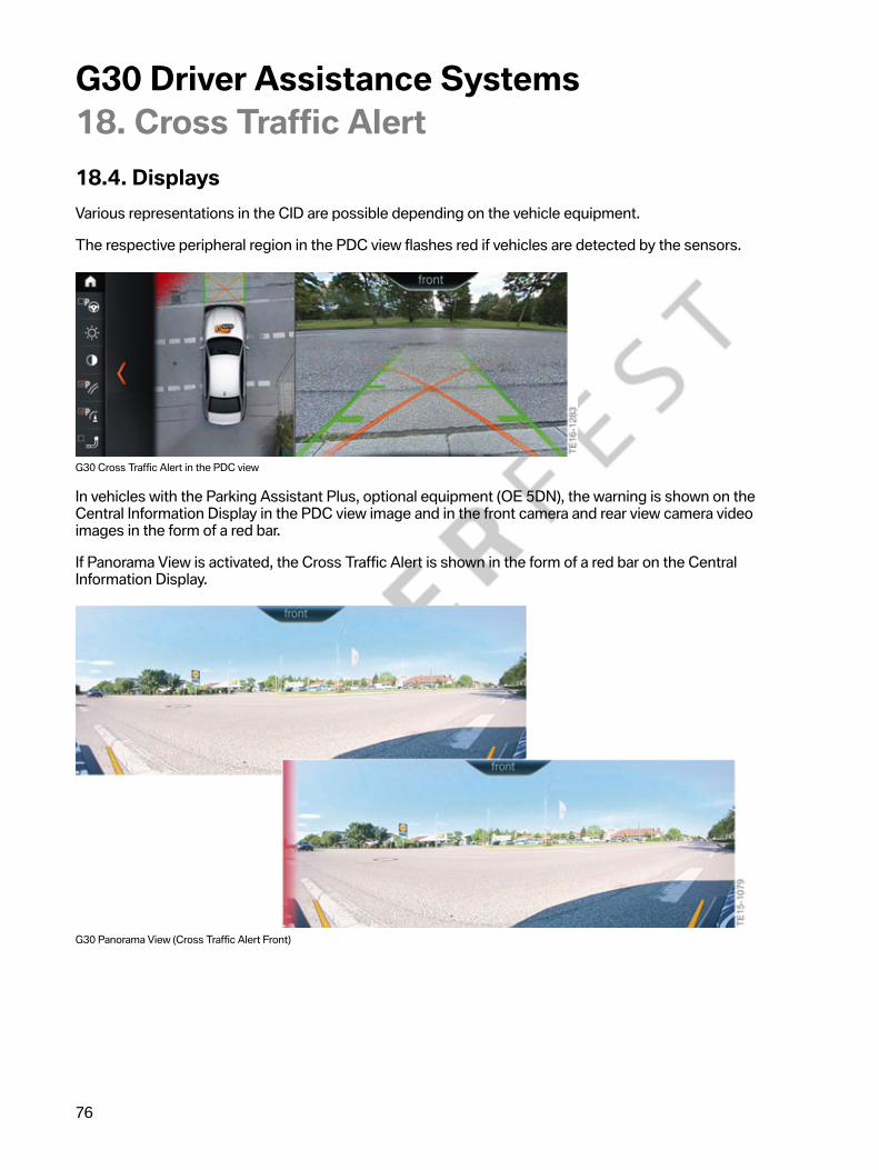
G30�Driver�Assistance�Systems18.�Cross�Traffic�Alert
76
18.4.�DisplaysVarious�representations�in�the�CID�are�possible�depending�on�the�vehicle�equipment.
The�respective�peripheral�region�in�the�PDC�view�flashes�red�if�vehicles�are�detected�by�the�sensors.
G30�Cross�Traffic�Alert�in�the�PDC�view
In�vehicles�with�the�Parking�Assistant�Plus,�optional�equipment�(OE�5DN),�the�warning�is�shown�on�theCentral�Information�Display�in�the�PDC�view�image�and�in�the�front�camera�and�rear�view�camera�videoimages�in�the�form�of�a�red�bar.
If�Panorama�View�is�activated,�the�Cross�Traffic�Alert�is�shown�in�the�form�of�a�red�bar�on�the�CentralInformation�Display.
G30�Panorama�View�(Cross�Traffic�Alert�Front)

G30�Driver�Assistance�Systems18.�Cross�Traffic�Alert
77
G30�Panorama�View�(Cross�Traffic�Alert�Rear)
The�Cross�Traffic�Alert�is�available�to�the�driver�for�both�the�front�and�rear�views.

G30�Driver�Assistance�Systems18.�Cross�Traffic�Alert
78
18.5.�OperationCross�Traffic�Alert�can�be�switched�on�and�off�via�the�iDrive�menu�by�making�the�following�selection�viathe�controller:
• "My�Vehicle"• "Vehicle�settings"• "Parking"• "Cross�traffic�alert"
G30�Cross�Traffic�Alert�activation�on�the�CID
Index Explanation1 "Vehicle�settings"2 "Parking"3 "Cross�traffic�alert"�(switching�the�Cross�Traffic�Alert�on�and�off)
If�the�Cross�Traffic�Alert�has�been�activated�in�the�iDrive�menu,�the�function�is�switched�onautomatically�as�soon�as�the�Park�Distance�Control�or�Panorama�View�is�active.
The�Cross�Traffic�Alert�is�deactivated�automatically�in�the�following�situations:
• If�the�driver's�vehicle�is�travelling�at�a�speed�higher�than�walking�speed�(threshold�valueapproximately�4�mph�(7 km/h)).
• If�the�Traffic�Jam�Assistant�is�active.• If�the�driver�is�currently�parking�using�the�Parking�Maneuvering�Assistant.

G30�Driver�Assistance�Systems18.�Cross�Traffic�Alert
79
18.6.�Limits�of�the�systemThe�function�may�be�restricted�in�the�following�situations:
• If�there�are�other�objects�in�the�field�of�view�of�the�sensors�that�are�concealing�the�cross�traffic.• Heavy�fog,�rain�or�snow.• If�the�bumper�is�dirty�or�iced�over.• If�stickers�have�been�attached�near�the�radar�sensors�on�the�bumper.• If�the�speed�of�the�approaching�vehicle�is�very�high.• If�crossing�objects�are�moving�very�slowly.• On�sharp�bends.
If�a�trailer�socket�is�being�used,�for�example�to�operate�a�trailer�or�bicycle�carrier,�the�Cross�Traffic�Alertis�not�available�for�the�area�behind�the�vehicle.
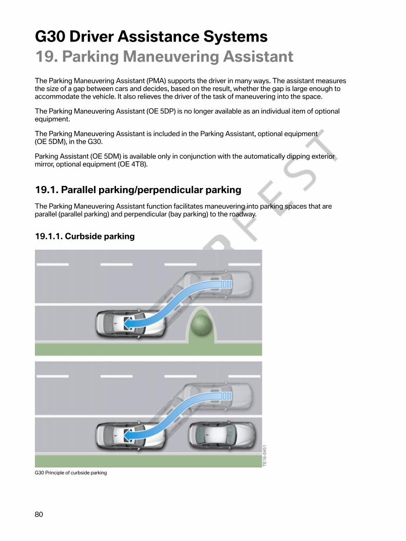
G30�Driver�Assistance�Systems19.�Parking�Maneuvering�Assistant
80
The�Parking�Maneuvering�Assistant�(PMA)�supports�the�driver�in�many�ways.�The�assistant�measuresthe�size�of�a�gap�between�cars�and�decides,�based�on�the�result,�whether�the�gap�is�large�enough�toaccommodate�the�vehicle.�It�also�relieves�the�driver�of�the�task�of�maneuvering�into�the�space.
The�Parking�Maneuvering�Assistant�(OE 5DP)�is�no�longer�available�as�an�individual�item�of�optionalequipment.
The�Parking�Maneuvering�Assistant�is�included�in�the�Parking�Assistant,�optional�equipment(OE 5DM),�in�the�G30.
Parking�Assistant�(OE 5DM)�is�available�only�in�conjunction�with�the�automatically�dipping�exteriormirror,�optional�equipment�(OE 4T8).
19.1.�Parallel�parking/perpendicular�parkingThe�Parking�Maneuvering�Assistant�function�facilitates�maneuvering�into�parking�spaces�that�areparallel�(parallel�parking)�and�perpendicular�(bay�parking)�to�the�roadway.
19.1.1.�Curbside�parking
G30�Principle�of�curbside�parking

G30�Driver�Assistance�Systems19.�Parking�Maneuvering�Assistant
81
19.1.2.�Perpendicular�parking
G30�Principle�of�perpendicular�parking
19.2.�System�componentsBelow�is�an�overview�of�important�sensors�and�operating�elements:
• The�parking�assistance�button�is�the�central�control�panel�for�the�Parking�ManeuveringAssistant�function�(position 8).
• Two�additional�ultrasonic�sensors�in�the�front�bumper�measure�parking�spaces�while�driving(position 1).
• The�distance�from�an�obstruction�is�measured�by�four�ultrasonic�sensors�in�the�rear�bumperpanel�and�four�additional�ultrasonic�sensors�in�the�front�bumper�panel�(positions�11�and�19).
• Two�additional�ultrasonic�sensors�are�installed�in�the�rear�bumper�to�precisely�detect�the�sizeof�a�transverse�parking�space�during�the�parking�maneuver.�The�additional�ultrasonic�sensorsmeasure�the�distance�to�detected�objects.

G30�Driver�Assistance�Systems19.�Parking�Maneuvering�Assistant
82
G30�Parking�Maneuvering�Assistant�system�components
Index Explanation1 Ultrasonic�sensors�of�Parking�Maneuvering�Assistant�(PMA)2 Digital�Motor�Electronics�(DME)3 Body�Domain�Controller�(BDC)4 Central�Information�Display�(CID)5 Head�Unit�High6 Advanced�Crash�Safety�Module�(ACSM)7 Controller�(CON)

G30�Driver�Assistance�Systems19.�Parking�Maneuvering�Assistant
83
Index Explanation8 Parking�assistance�button9 Ultrasonic�sensors,�Park�Distance�Control,�rear�side10 Control�unit�for�Parking�Maneuvering�Assistant�(PMA)11 Ultrasonic�sensors,�Park�Distance�Control,�rear12 Steering�column�switch�cluster�(SZL)13 Instrument�panel�(KOMBI)14 Control�unit�for�Optional�Equipment�System�(SAS)15 Dynamic�Stability�Control�(DSC)16 Digital�Engine�Electronics�2�(DME2)17 Electronic�Power�Steering�(EPS)18 Electronic�transmission�control�(EGS)19 Ultrasonic�sensors�for�Park�Distance�Control,�front
19.3.�System�wiring�diagramThe�system�wiring�diagram�on�the�next�page�shows�an�overview�of�the�system�components�used�whenparking�and�maneuvering�the�vehicle.�Depending�on�the�vehicle�equipment,�partial�scopes�may�also�beinstalled.

G30�Driver�Assistance�Systems19.�Parking�Maneuvering�Assistant
84
G30�Parking�and�maneuvering�system�wiring�diagram

G30�Driver�Assistance�Systems19.�Parking�Maneuvering�Assistant
85
Index Explanation1 Ultrasonic�sensors�for�Park�Distance�Control,�front2 Front�camera3 Ultrasonic�sensors�for�Parking�Maneuvering�Assistant�(PMA)4 Dynamic�Stability�Control�(DSC)5 Electronic�Power�Steering�(EPS)6 Digital�Motor�Electronics�(DME)7 Electronic�transmission�control�(EGS)8 CAN�terminator9 CAN�terminator10 Fuse�for�front�right�power�distribution�box11 Right�side�view�camera12 Body�Domain�Controller�(BDC)13 Remote�control�receiver�(FBD)14 Fuse�for�rear�right�power�distribution�box15 Control�unit�for�Parking�Maneuvering�Assistant�(PMA)16 Remote�Control�Parking�aerial17 Ultrasonic�sensors,�Park�Distance�Control,�rear�side18 Ultrasonic�sensors,�Park�Distance�Control,�rear19 Rear�view�camera�(RFK)20 Controller�(CON)21 Parking�assistance�button�and�button�for�camera�activation22 Advanced�Crash�Safety�Module�(ACSM)23 Steering�column�switch�cluster�(SZL)24 Instrument�panel�(KOMBI)25 Control�unit�for�Optional�Equipment�System�(SAS)26 Central�Information�Display�(CID)27 Head�Unit�High28 CAN�terminator29 Left�side�view�camera30 Top�Rear�Side�View�Camera�(TRSVC)�control�unit

G30�Driver�Assistance�Systems19.�Parking�Maneuvering�Assistant
86
19.4.�Control�unitIn�vehicles�with�the�Parking�Maneuvering�Assistant,�both�the�Park�Distance�Control�and�ParkingManeuvering�Assistant�functions�are�provided�by�the�PMA�control�unit.
G30�Control�unit�for�Parking�Maneuvering�Assistant�(PMA)
19.5.�Functional�principleThe�system�measures�potential�parking�spaces�when�driving�past�at�a�speed�below�approximately22�mph�(35 km/h)�even�without�the�system�having�been�activated.
The�parking�spaces�are�measured�by�two�additional�ultrasonic�sensors,�which�are�integrated�intothe�front�wheel�arch.�Two�additional�ultrasonic�sensors�are�installed�in�the�rear�bumper�in�the�G30�toprecisely�detect�the�size�of�a�perpendicular�parking�space�during�the�parking�maneuver.�The�additionalultrasonic�sensors�measure�the�distance�to�detected�objects.
The�four�sensors�are�connected�to�the�Parking�Maneuvering�Assistant�(PMA)�control�unit,�which�alsoincorporates�the�Park�Distance�Control�function.�The�function�of�the�four�ultrasonic�sensors�is�similarto�that�of�the�Park�Distance�Control�(PDC).�Ultrasonic�pulses�are�sent�and�echo�impulses�are�received.
If�a�parking�space�of�a�sufficient�length�and�width�is�found�and�the�system�is�activated,�the�driver�isshown�the�space�on�the�Central�Information�Display.
When�searching�for�a�parking�space�and�when�parking,�all�relevant�information�is�presented�to�thedriver�in�an�integrated�display;�from�the�parking�space�itself�to�the�status�of�the�parking�assistant�andcorresponding�handling�instructions�to�distances�from�other�objects.
The�driver�is�still�responsible�for�monitoring�the�vehicle�environment�and�can�intervene�in�theautomatic�parking�maneuver�at�any�time�if�required�due�to�the�vehicle�environment.
The�Parking�Maneuvering�Assistant�(PMA)�takes�over�complete�control�of�the�vehicle�includingsteering,�braking�and�gear�selection.

G30�Driver�Assistance�Systems19.�Parking�Maneuvering�Assistant
87
19.5.1.�Personal�responsibility
• Directly�monitor�gaps�and�the�parking�procedure�and�intervene�if�necessary,�as�otherwisethere�is�a�risk�of�accidents.
• If�a�parking�space�that�has�already�been�measured�changes,�the�system�does�not�take�this�intoaccount.
• The�system�does�not�take�loads�that�project�above�the�vehicle�into�account�during�parking.• The�Parking�Maneuvering�Assistant�(PMA)�may�steer�the�vehicle�over�or�up�onto�curbs.�You
should�therefore�use�the�facility�for�active�intervention�at�any�time�with�caution�as�you�mayotherwise�damage�wheels�and�tires�or�the�vehicle�itself.
The�Parking�Maneuvering�Assistant�(PMA)�does�not�relieve�the�driver�of�personal�responsibility�duringparking.�Therefore,�be�attentive�in�order�to�be�able�to�actively�intervene�at�any�time.�Otherwise,�there�isa�risk�of�an�accident.
19.6.�Functional�prerequisitesTo�use�the�Parking�Maneuvering�Assistant�function,�the�following�basic�prerequisites�must�be�met:
• The�doors�must�be�closed• The�trunk�lid�must�be�closed• The�driver's�seat�belt�must�be�fastened• The�parking�brake�must�be�released

G30�Driver�Assistance�Systems19.�Parking�Maneuvering�Assistant
88
19.6.1.�Measuring�parking�spacesParking�spaces�are�measured�while�driving.�The�following�parameters�apply:
• Driving�forwards�straight-ahead�up�to�approximately�22�mph�(35 km/h)• Maximum�distance�to�the�row�of�parked�vehicles:�5�ft�(1.5 m)
Detecting�the�curb
If�a�curb�is�detected�within�the�range�of�the�ultrasonic�sensor�while�the�system�is�searching�for�aparking�space,�the�parking�space�is,�for�the�most�part,�a�space�that�is�parallel�to�the�road.
In�the�case�of�parking�spaces�that�are�perpendicular�to�the�roadway,�the�curb�is�usually�outside�thedetection�range�of�the�ultrasonic�sensors�(range�approximately�14�ft�(4.2 m)).
G30�Curb�detection�via�the�ultrasonic�sensors
Index Explanation1 Range�approximately�4.2 m;�opening�angle�of�ultrasonic�sensors�vertical�±�30°2 Curb�detection
Additional�information�on�parking�spaces�suitable�for�the�Parking�Maneuvering�Assistant�may�be�foundin�the�“G12�Driver�Assistance�Systems”�reference�manual�(section�19.5.2-19.5.4).

G30�Driver�Assistance�Systems19.�Parking�Maneuvering�Assistant
89
19.7.�OperationThere�are�two�ways�to�activate�the�Parking�Maneuvering�Assistant�function:
• Activation�via�parking�assistance�button• Activation�by�"Engaging�reverse�gear"�followed�by�"iDrive�controller�operation"
Activation�via�parking�assistance�button
When�the�PMA�is�activated�via�the�parking�assistance�button�in�the�center�console,�the�parkingassistance�menu�in�the�Central�Information�Display�(CID)�is�displayed.�As�soon�as�a�parking�space�isfound,�the�driver�receives�handling�instructions�that�guide�him�though�the�parking�procedure�with�thesupport�of�the�system.
G30�Switch�block�with�parking�assistance�button
Index Explanation1 Parking�assistance�button
Activation�by�"Engaging�reverse�gear"�followed�by�"iDrive�controller�operation"
When�reverse�gear�is�engaged,�the�Parking�Maneuvering�Assistant�menu�is�displayed�on�theCentral�Information�Display�accompanied�by�the�status�of�the�parking�space�search.�The�ParkingManeuvering�Assistant�(PMA)�is,�however,�not�yet�activated.�This�is�indicated�to�the�driver�by�theParking�Maneuvering�Assistant�symbol�in�the�toolbar�of�the�Central�Information�Display.�In�order�topark�supported�by�the�system,�the�parking�operation�must�be�activated�via�the�controller�by�selectingthe�corresponding�symbol�in�the�symbol�bar�at�the�Central�Information�Display�(CID).

G30�Driver�Assistance�Systems19.�Parking�Maneuvering�Assistant
90
19.7.1.�Park�procedureAs�soon�as�a�parking�space�is�found,�the�driver�is�instructed�to�stop�the�vehicle�and�confirm�the�parkingspace�by�using�the�turn�indicator�corresponding�to�the�parking�direction.�During�the�entire�parkingprocedure,�the�driver�receives�further�instructions�that�guide�him�though�the�entire�parking�procedurewith�the�support�of�the�system.
The�driver�is�prompted�to�take�his�hands�from�the�steering�wheel�during�automatic�parking�and�holddown�the�parking�assistance�button�until�the�parking�procedure�is�complete.
19.7.2.�Deactivation�criteria
Manual�deactivation�criteria
The�Parking�Maneuvering�Assistant�(PMA)�can�be�deactivated�at�any�time,�if�necessary,�by�the�drivervia�the�controller�by�selecting�the�corresponding�symbol�in�the�symbol�bar�on�the�Central�InformationDisplay�(CID).�Another�way�to�deactivate�the�Parking�Maneuvering�Assistant�(PMA)�is�to�release�theparking�assistance�button�in�the�switch�block�next�to�the�iDrive�controller.
If�a�fault�develops,�a�Check�Control�message�"The�PDC�has�malfunctioned.�Have�system�checked."�isdisplayed�in�the�Central�Information�Display�(CID).
Automatic�deactivation�criteria
The�Parking�Maneuvering�Assistant�(PMA)�is�switched�off�automatically�when�the�following�eventsoccur:
• The�parking�assistance�button�is�released.• The�driver�holds�on�to�the�steering�wheel�or�steers�himself.• A�gear�is�selected�that�does�not�correspond�to�the�instruction�on�the�control�display.• When�accelerating.• The�parking�brake�is�secured.• The�turn�indicator�opposite�the�required�parking�side�is�switched�on.• At�speeds�above�approximately�6�mph�(10 km/h).• Possibly�if�the�roadway�is�covered�with�snow�or�is�slippery.• The�trunk�lid�is�open.• Possibly�if�the�objects�are�difficult�to�overcome,�e.g.�curbs.• If�obstructions�suddenly�appear.• A�maximum�number�of�parking�maneuvers�or�the�parking�duration�has�been�exceeded.

G30�Driver�Assistance�Systems19.�Parking�Maneuvering�Assistant
91
19.8.�Limits�of�the�systemThe�detection�of�objects�can�test�the�ultrasonic�measurement�system�to�its�limits.�Several�examplesof�this�are�shown�below:
• With�trailer�towbars�and�couplings.• If�the�objects�are�thin�or�wedge-shaped.• If�the�objects�are�projecting�and�elevated,�e.g.�wall�projections�or�loads.• If�the�objects�have�corners�and�sharp�edges.• If�the�objects�have�fine�surfaces�or�structures,�e.g.�fences.
Low�objects�that�are�already�displayed,�e.g.�curbs,�may�fall�within�the�blind�spot�of�the�sensors�beforeor�after�a�continuous�alarm�sounds.�It�would�not�be�possible�to�detect�objects�that�are�higher�up�andprojecting,�e.g.�wall�projections.�Parking�spaces�may�be�detected�although�these�are�not�suitable.
There�may�be�other�functional�limitations�in�the�following�situations,�for�example:
• If�the�sensors�are�soiled�or�iced�up.• Heavy�fog,�rain�or�snow.• On�uneven�surfaces,�e.g.�gravel�roads.• On�slippery�surfaces.• On�steep�inclines�or�downhill�gradients.• If�leaves�have�gathered�or�snow�has�piled�up�in�the�parking�space.
To�ensure�the�ultrasonic�sensors�remain�fully�operational,�they�must�be�kept�clean�and�free�of�ice.When�cleaning�the�sensors�using�a�high�pressure�cleaner,�avoid�direct�and�sustained�contact�with�ahigh-pressure�water�jet.�Furthermore,�when�using�high�pressure�cleaners,�a�distance�of�at�least�1�ft(30 cm)�from�the�sensors�must�be�maintained.
The�Parking�Maneuvering�Assistant�(PMA)�cannot�replace�the�driver's�personal�judgement�of�thetraffic�situation.�Also�check�the�traffic�situation�around�the�vehicle�by�looking�around,�otherwise�theremay�be�a�risk�of�an�accident�as�a�result�of�road�users�or�objects�which�lie�outside�the�detection�range�ofthe�Park�Distance�Control.�Loud�sound�sources�outside�and�inside�the�vehicle�may�mask�the�acousticsignals�of�the�Parking�Maneuvering�Assistant�(PMA)�or�the�Park�Distance�Control�(PDC).

G30�Driver�Assistance�Systems20.�Remote�Control�Parking
92
The�Remote�Control�Parking�assistant�became�available�for�the�first�time�in�the�G12.�This�assistancesystem�enables�the�vehicle�to�be�maneuvered�in�and�out�of�a�parking�space�remotely�using�theBMW display�key.�The�system�assists�the�driver�to�park�in�tight�parking�bays�or�enclosed�spaces�(suchas�garages�or�in�multi-story�car�parks),�where�it�is�difficult�for�the�driver�to�get�in�and�out�of�the�vehicle.
G30�Remote�Control�Parking
Automatic�parking�in�and�reversing�out�of�bay�parking�spaces�is�possible�by�activating�the�"remote-controlled�parking"�function�on�the�display�key.
The�Remote�Control�Parking,�optional�equipment�(OE�5DV),�is�only�available�for�certain�models�andnational-market�versions.�In�addition,�the�assistance�system�can�only�be�ordered�in�conjunction�withthe�following�equipment:
• Steptronic�sport�transmission�(OE 2TB)• Comfort�Access�(OE�322)• BMW�display�key�(OE�3DS)• Parking�Assistant�Plus�(OE 5DN)• Professional�navigation�system�(OE 609)
The�entire�parking�procedure�is�monitored�by�the�Park�Distance�Control�and�Parking�ManeuveringAssistant�ultrasonic�sensors�and�the�Surround�View�cameras�within�their�system�limits.�The�driver�isoutside�the�vehicle�while�it�is�being�parked.�He�must,�however,�check�the�situation�around�the�vehicleby�looking�around�and�can�cancel�the�parking�procedure�at�any�time�using�the�BMW�display�key.�If�thedriver�leaves�the�operating�range,�the�vehicle�stops�automatically.

G30�Driver�Assistance�Systems20.�Remote�Control�Parking
93
G30�Remote�Control�Parking
Index Explanation1 BMW�display�key2 Operating�area�for�remote�controlled�parking
20.1.�OperationThe�touch�screen�display�and�Remote�Control�Parking�button�on�the�BMW�display�key�are�used�tooperate�the�Remote�Control�Parking�function.�This�makes�the�function�intuitive�to�use�and�provides�thedriver�with�messages�on�the�action�required�to�operate�the�function�and�system�limits.
The�remote-controlled�parking�button�must�be�pressed�and�held�throughout�the�entire�parkingprocedure,�otherwise�parking�will�not�start�or�the�vehicle�will�initiate�emergency�braking�if�the�buttonis�released�(electromechanical�parking�brake�subsequently�applied).�If�the�data�transfer�between�thevehicle�and�BMW�display�key�is�interrupted,�the�vehicle�is�also�decelerated�to�a�standstill,�as�the�datacan�only�be�transmitted�in�the�vicinity�of�the�vehicle.
If�objects�are�detected,�the�system�brakes�the�vehicle�to�a�stop�and�prevents�it�from�rolling�away(activates�the�service�brake�and�engages�selector�position�"P").�A�corresponding�notification�is�shownto�the�driver�in�the�BMW�display�key.
The�braking�process�because�of�a�detected�obstacle�is�initiated�only�if�this�obstacle�is�permanentlydetected�by�the�ultrasonic�sensors.�Objects�that�are,�for�example,�too�flat�or�are�outside�the�detectionrange�of�the�ultrasonic�sensors�cannot�be�detected.�If�the�driver�is�not�paying�attention,�there�is�a�riskof�an�accident�or�danger�of�damage.

G30�Driver�Assistance�Systems20.�Remote�Control�Parking
94
The�function�can�continue�within�30 seconds�if�the�detected�object�has�been�removed.�If�this�timeperiod�expires,�Remote�Control�Parking�switches�off�the�engine�and�applies�the�electric�parking�brake.The�parking�procedure�can�be�continued�by�activating�the�system�again.
The�driver�must�meet�the�following�basic�prerequisites�before�the�Remote�Control�Parking�functioncan�be�used:
• Position�the�vehicle�facing�forwards�and�as�centrally�and�straight�as�possible�in�front�of�theparking�space�(maximum�3°�turn�angle�and�4�in�(10�cm)�offset�to�the�center�of�the�parkingspace�are�compensated�for�by�small�steering�adjustments).
• The�vehicle�should�be�no�more�than�approximately�6½�ft�(2 m)�away�from�the�parking�space.• Apply�the�electromechanical�parking�brake�to�secure�the�vehicle�against�rolling�away.• Switch�off�driving�readiness�with�the�start/stop�button.
The�graphic�below�shows�an�overview�of�activation�of�the�Remote�Control�Parking�function�and�itsoperating�logic.
Activation:�Remote�Control�Parking
Index Explanation1 Activate�the�display�by�pressing�the�button�on�the�side�of�the�key�and�then
unlock�it�by�swiping�your�finger�upwards�on�the�display.2 Establish�a�connection�to�the�vehicle.�To�do�so,�either�change�to�the�Remote
Control�Parking�menu�and�then�hold�down�the�Remote�Control�Parking�button,or�hold�down�the�Remote�Control�Parking�button�immediately�after�unlockingthe�display.
3 Start�the�engine�using�the�BMW�display�key.4 Specify�the�direction�of�travel�of�the�vehicle�by�pressing�the�corresponding
arrow�symbol�on�the�button.�The�vehicle�will�move�all�the�time�the�arrowsymbol�is�touched.�If�the�direction�arrow�is�released,�the�vehicle�brakes�to�astop�by�means�of�a�gentle�brake�intervention.
The�maximum�distance�the�vehicle�will�travel�corresponds�to�1½�times�the�vehicle�length.
G30�Driver�Assistance�Systems20.�Remote�Control�Parking
95
The�BMW�display�key�can�likewise�show�the�driver�a�variety�of�targeted�instructions�and�faultmessages,�giving�him�direct�feedback�and�information�on�operating�the�Remote�Control�Parkingfunction.
The�system�does�not�relieve�the�driver�of�personal�responsibility�for�correctly�judging�the�trafficand�parking�situation.�Due�to�the�limits�of�the�system,�it�cannot�automatically�react�adequately�in�allsituations.�There�is�a�risk�of�an�accident�or�danger�of�material�damage.�The�driver�should�check�thetraffic�conditions�and�parking�situation,�and�react�accordingly�if�required.
Unauthorized�persons,�e.g.�children,�can�set�the�vehicle�in�motion�using�the�BMW�display�key,�withoutanyone�being�in�the�vehicle.�There�is�still�a�risk�of�an�accident.�Protect�the�BMW�display�key�fromunauthorized�use.
20.1.1.�Cut-off�events
Cut-off�events�include:
• Opening�the�doors,�hood�or�trunk�lid.• Pressing�the�brake�or�accelerator�pedal�(carried�out�by�a�person
inside�the�vehicle).• Steering�interventions.• Operating�the�electric�parking�brake�or�gear�selector�switch�(carried�out�by�a
person�inside�the�vehicle).• Exceeding�the�maximum�movement�range.• Selecting�another�function�using�the�BMW�display�key.• System�fault.• Failure�or�contamination�of�the�ultrasonic�sensors.• State�of�charge�of�the�BMW�display�key�battery�too�low�(remote-controlled
parking�not�possible�below�approximately�50%�absolute�state�of�charge).• Releasing�the�Remote�Control�Parking�button.• Background�noise.• BMW�display�key�outside�the�operating�range.• Maximum�speed�exceeded.• Exceeding�the�5%�maximum�incline�or�downhill�gradient.

96
G30 Driver Assistance Systems20. Remote Control Parking20.2. Requirements on the parking spaceThe following graphic illustrates which conditions or prerequisites the parking space must meet to beable to use the Remote Control Parking function.
G30 Prerequisites for Remote Control Parking
Index ExplanationA Potential parking area
Operating rangeMinimum parking space width 8.8 ft (2.7 m)Maximum movement range 29.5 ft (9 m)Distance to parking space, maximum 6.5 ft (2 m)Maximum distance of driver from side of vehicle 5 ft (1.5 m)Maximum 3° turn angle and 4 in (10 cm) offset to the center of the parkingspace are compensated for by small steering adjustmentsMaximum distance of driver from rear of vehicle approximately 10 ft (3 m)
B12345
6
The Remote Control Parking assistance system can be used on gradients of no more than 5%. Use ofthe assistance system in two-level garages is not intended.

G30�Driver�Assistance�Systems20.�Remote�Control�Parking
97
20.3.�System�overviewThe�Top�Rear�Side�View�Camera�(TRSVC)�and�Optional�Equipment�System�(SAS)�control�units�are�thecentral�system�components�of�the�Remote�Control�Parking�function.�The�Park�Distance�Control�(PDC)and�Parking�Maneuvering�Assistant�(PMA)�ultrasonic�sensors,�and�the�Surround�View�cameras�recordthe�area�around�the�vehicle.�The�Comfort�Access�aerials�and�Remote�Control�Parking�aerial�are�used�todetect�the�location�of�the�driver�and�BMW�display�key.
The�following�graphic�shows�the�components�required�for�Remote�Control�Parking�in�addition�to�thosethat�make�up�the�Parking�Maneuvering�Assistant�function.
G30�Remote�Control�Parking�system�components
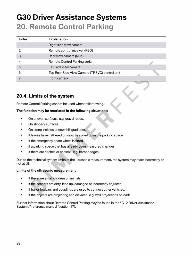
G30�Driver�Assistance�Systems20.�Remote�Control�Parking
98
Index Explanation1 Right�side�view�camera2 Remote�control�receiver�(FBD)3 Rear�view�camera�(RFK)4 Remote�Control�Parking�aerial5 Left�side�view�camera6 Top�Rear�Side�View�Camera�(TRSVC)�control�unit7 Front�camera
20.4.�Limits�of�the�systemRemote�Control�Parking�cannot�be�used�when�trailer�towing.
The�function�may�be�restricted�in�the�following�situations:
• On�uneven�surfaces,�e.g.�gravel�roads.• On�slippery�surfaces.• On�steep�inclines�or�downhill�gradients.• If�leaves�have�gathered�or�snow�has�piled�up�in�the�parking�space.• If�the�emergency�spare�wheel�is�fitted.• If�a�parking�space�that�has�already�been�measured�changes.• If�there�are�ditches�or�chasms,�e.g.�harbor�edges.
Due�to�the�technical�system�limits�of�the�ultrasonic�measurement,�the�system�may�react�incorrectly�ornot�at�all.
Limits�of�the�ultrasonic�measurement
• If�there�are�small�children�or�animals.• If�the�sensors�are�dirty,�iced�up,�damaged�or�incorrectly�adjusted.• If�trailer�towbars�and�couplings�are�used�to�connect�other�vehicles.• If�the�objects�are�projecting�and�elevated,�e.g.�wall�projections�or�loads.
Further�information�about�Remote�Control�Parking�may�be�found�in�the�“G12�Driver�AssistanceSystems”�reference�manual�(section�17).

G30�Driver�Assistance�Systems21.�Cruise�Control
99
21.1.�IntroductionTwo�cruise�control�functions�can�be�used�in�the�G30.�The�cruise�control�with�braking�function,Dynamic�Cruise�Control�(DCC),�is�part�of�the�standard�equipment.
ACC Stop&Go�can�be�obtained�if�the�customer�opts�for�the�Active�Driving�Assistant�Plus,�optionalequipment�(OE 5AT),�as�it�is�contained�in�this�equipment�package.
The�cruise�control�systems�support�the�driver�with�adapting�the�speed,�distance�and�driving�style�tothe�traffic�conditions,�but�do�not�relieve�him�of�his�responsibility.�The�driver�must�actively�intervene,e.g.�by�braking,�steering�or�taking�evasive�action,�as�otherwise�there�is�a�risk�of�an�accident.
21.2.�Cruise�control�with�braking�functionThe�cruise�control�with�braking�function�is�included�as�part�of�the�G30's�standard�equipment.�Thesystem�is�also�known�as�"Dynamic�Cruise�Control"�(DCC).�Dynamic�Cruise�Control�(DCC)�supportsthe�driver�on�roads�with�less�traffic�by�keeping�the�speed�constant�irrespective�of�rolling�resistances(incline,�downhill�driving�and�vehicle�load).�In�spite�of�the�support,�the�driver�remains�responsible�forcontrol�of�the�vehicle.�It�is�possible�to�override�the�DCC�function�at�any�time�by�braking�or�acceleratingthe�vehicle.
21.2.1.�OperationThe�driver�has�the�option�of�adjusting�the�set�speed�in�small�or�large�increments,�which�is�then�setand�maintained�by�the�system�by�controlling�the�drive�and�brakes.�It�can�be�changed�using�the�left-hand�switch�block�on�the�multifunction�steering�wheel�(MFL).�The�speed�is�increased�or�reducedby�1 mph�by�tapping�the�rocker�switch.�Each�time�the�rocker�button�is�pressed�beyond�the�pressurepoint,�the�speed�increases�or�reduces�by�5 mph.�The�DCC�steadily�maintains�a�selected�speed�fromapproximately�20�mph�(30�km/h).
The�set�speed�is�indicated�in�the�instrument�cluster�in�the�familiar�way;�by�a�mark�that�moves�round�thespeed�reading.�Notes�are�added�to�the�displays�in�the�instrument�cluster,�if�necessary.
If�the�vehicle's�own�deceleration�is�not�sufficient�to�maintain�the�preset�speed,�the�brake�is�activatedaccordingly.
If�ECO�PRO�or�SPORT�mode�is�activated,�cruise�control�is�also�set�to�a�fuel-efficient�or�sporty�drivingstyle.�Due�to�the�fuel-efficient�driving�style�in�ECO PRO�driving�mode,�in�some�situations�the�vehicle'sspeed�may�exceed�or�drop�below�the�set�speed,�for�example�on�downhill�gradients�or�inclines.

G30�Driver�Assistance�Systems21.�Cruise�Control
100
G30�Buttons�of�the�Dynamic�Cruise�Control�(DCC)
Index Explanation1 Button�for�activating�or�deactivating�the�Dynamic�Cruise�Control�(DCC)2 Rocker�switch�for�changing�the�set�speed3 “SET”�button�for�setting�the�speed�of�cruise�control4 Button�for�calling�up�a�saved�set�speed/temporarily�switching
off�the�cruise�control
The�system�is�interrupted�automatically�in�the�following�situations:
• If�the�brakes�are�used.• If�the�selector�lever�position�is�moved�out�of�position�"D".• If�the�Dynamic�Traction�Control�(DTC)�is�activated�or�the
Dynamic�Stability�Control�(DSC)�is�deactivated.• If�the�Dynamic�Stability�Control�(DSC)�is�performing�an�adjustment.
21.3.�Active�Cruise�Control�with�Stop&Go�functionThe�Active�Cruise�Control�with�Stop&Go�function�(ACC Stop&Go)�is�offered�as�a�function�of�the�ActiveDriving�Assistant�Plus,�optional�equipment�(OE�5AT),�for�the�G30.
ACC�Stop&Go�adjusts�a�driver-specified�set�speed�and,�if�required�by�the�traffic�situation,�alsoautomatically�adjusts�the�preselected�following�distance�to�the�vehicle�driving�ahead�(detectedvehicles�include�passenger�cars,�trucks�and�motorbikes).�The�application�range�of�ACC�Stop&Goranges�from�higher�speeds�down�to�a�standstill.�The�distance�and�the�speed�are�automatically�adjustedin�this�range.

G30�Driver�Assistance�Systems21.�Cruise�Control
101
G30�Active�Cruise�Control�(ACC)�Stop&Go
Depending�on�the�stationary�time,�driving�off�from�a�standstill�is�performed�automatically�or�inresponse�to�a�prompt�by�the�driver.�ACC Stop&Go�not�only�detects�vehicles�that�are�slowly�comingto�a�stop,�but�also�stationary�vehicles.
Due�to�improved�monitoring�in�front�of�the�vehicle,�the�system�is�capable�of�reacting�more�quickly�tovehicles�swinging�in�and�out�and�turning�off.
The�extended�application�range�has�been�achieved�by�the�incorporation�of�the�KAFAS�stereo�camera.Image�data�is�evaluated�by�the�ACC Stop&Go�system.�The�KAFAS�control�unit�clearly�detects�vehicleswhen�their�rear�ends�are�recorded�by�the�camera.�In�addition,�the�KAFAS�control�unit�ensures�that�thedriving�lane�information,�vehicle�positions�and�movements�are�determined.

G30�Driver�Assistance�Systems21.�Cruise�Control
102
Object�detection�provided�by�a�combination�of�radar�sensor�and�KAFAS�stereo�camera.
In�addition�to�image�data,�radar�data�is�also�gathered�and�evaluated�by�the�radar�sensors.�This�fusionof�image�and�radar�data�makes�possible�the�clear�identification�of�lane�markings�and�the�distinctionbetween�stationary�vehicles�and�other�fixed�objects.

G30�Driver�Assistance�Systems21.�Cruise�Control
103
G30�Radar�sensor/KAFAS�stereo�camera�fusion:�Radar�sensor�object�detection
A�77 GHz�radar�sensor�emits�bundled�electromagnetic�waves.�The�echoes�reflected�by�objects�arereceived�and�evaluated�by�the�radar�sensor.�This�enables�information�about�objects�located�in�front�ofthe�radar�sensor�to�be�obtained.�This�information�includes�size,�distance�and�the�deduced�speed.�Thesystem's�radar�sensor�can�identify�vehicles�ahead�up�to�a�distance�of�650�ft�(200 m),�to�a�large�extentirrespective�of�weather�conditions.

G30�Driver�Assistance�Systems21.�Cruise�Control
104
The�sensor�is�located�behind�the�air�inlet�grille�on�the�front�bumper.
G30�Installation�location�of�front�radar�sensor�for�ACC�Stop&Go
Index Explanation1 Removable�grille2 Sensor�for�ACC�Stop&Go
G30�Front�radar�sensor�for�ACC�Stop&Go
Index Explanation1 Adjustment�feature

G30�Driver�Assistance�Systems21.�Cruise�Control
105
Thanks�to�the�radar�sensor's�improved�detection�capability�and�alignment�with�the�image�data�fromthe�KAFAS�stereo�camera,�vehicles�in�neighboring�lanes�are�also�detected.�If�these�vehicles�are�drivingin�their�own�lane,�then�ACC�Stop&Go�adapts�the�speed�to�the�vehicle�pulling�in�or�vehicle�ahead.�As�aresult,�a�time�lag�selected�by�the�driver�is�constantly�maintained.
ACC�Stop&Go�adjusts�the�speed�if�there�is�no�vehicle�driving�directly�ahead�and�automaticallyswitches�to�distance�control�if�the�sensor�system�detects�a�slower�vehicle�in�its�lane.�The�system'sStop&Go�function�brings�the�vehicle�to�a�complete�standstill�if�necessary.
Detecting�the�vehicle�in�front�of�the�vehicle�in�front
Additionally�detecting�the�vehicle�in�front�of�the�vehicle�in�front�is�likewise�new�on�the�G30.
This�is�analyzed�using�the�sensors�already�fitted.�Object�detection�is�based�on�a�fusion�of�the�frontradar�sensor�and�the�KAFAS�stereo�camera.�Both�sensors�are,�in�principle,�capable�of�detecting�avehicle�two�positions�ahead.
In�most�cases,�the�vehicle�in�front�of�the�vehicle�in�front�is,�however,�concealed�by�the�vehicle�in�front,which�is�why�the�camera�can�generally�not�detect�it.�The�front�radar,�however,�consistently�providesgood�detection�quality�here�by�“looking�under”�the�vehicle�in�front.
The�advantages�of�this�are�as�follows:
• Improved�"driver-like"�speed�governing�behavior• Smoother�following�driving�(“ACC�cruising”)• Enhanced�dynamics�for�traffic�light-controlled�journeys• Driver-like�behavior�when�approaching�distant�objects
Evaluation�of�ultrasound�data
Since�both�the�front�radar�sensor�and�the�KAFAS�stereo�camera�are�only�of�limited�use�for�close-rangemonitoring,�the�ultrasonic�data�for�the�ACC Stop&Go�system�is�evaluated�for�the�first�time�on�the�G30.The�data�is�provided�by�the�front�ultrasonic�sensors�already�described.�These�are�needed�to�monitorthe�close�range�in�front�of�the�vehicle�for�freedom�from�obstacles.
Coupling�to�the�navigation�system
Improved�cornering�behavior�is�made�possible�by�coupling�ACC Stop&Go�to�the�navigation�system.This�contributes�to�a�further�improvement�of�driver-like�behavior.�This�also�takes�into�consideration�theintention�to�turn�off�the�road�and�intersections,�among�other�aspects.
Restart�time
The�restart�time�after�automatic�braking�to�a�stop�by�ACC Stop&Go�previously�of�approximately3 seconds�has�been�raised�to�approximately 30 seconds�on�the�G30.
The�prerequisite�for�extended�restarting�is�that�the�vehicle�is�located�on�a�highway�or�a�dividedhighway�outside�the�town.

G30�Driver�Assistance�Systems21.�Cruise�Control
106
If�the�vehicle�in�front�starts�driving�again�after�being�stopped�(for�more�than�approximately 3 secondsor�longer�than�approximately 30 seconds�on�highways�and�divided�highways),�a�note�is�shown�to�thedriver.�To�drive�off�again�the�driver�must�confirm�this�note�by�pressing�the�RES/CNCL�button�or�theaccelerator�pedal.
Additional�convenience�is�provided�by�the�extended�restart�time�without�driver�intervention.
ACC�Stop&Go�does�not�only�support�the�driver�in�flowing�traffic,�but�also�in�traffic�jam�situations,�bothon�multiple-lane�highways�and�ordinary�roads�and�on�urban�arterial�and�ring�roads.
The�adjustment�range�for�the�set�speed�is�limited�to�a�maximum�of�130�mph�(210 km/h).
If�ECO�PRO�or�SPORT�mode�is�activated,�the�Active�Cruise�Control�with�Stop&Go�function�is�alsoset�to�a�fuel-efficient�or�sporty�driving�style.�Due�to�the�fuel-efficient�driving�style�in�ECO PRO�drivingmode,�in�some�situations�the�vehicle's�speed�may�exceed�or�drop�below�the�set�speed,�for�example�ondownhill�gradients�or�inclines.

G30�Driver�Assistance�Systems21.�Cruise�Control
107
21.3.1.�Operation
Activation�and�deactivation
The�activation�and�deactivation�of�the�ACC�Stop&Go�and�the�Dynamic�Cruise�Control�are�almost�thesame.�ACC Stop&Go�can�either�be�activated�while�driving�or�at�a�standstill.�For�safety�reasons,�whenthe�vehicle�is�at�a�standstill�the�function�can�only�be�put�in�Standby�mode�or�deactivated�while�the�footbrake�is�applied.
If�the�function�is�active,�it�can�be�interrupted�by�pressing�the�RES/CNCL�button.�The�distance�andspeed�will�no�longer�be�maintained�and�the�set�speed�is�greyed�out�in�the�instrument�cluster.
The�driver�can�select�a�desired�distance�in�four�stages�using�the�left-hand�multifunction�button�on�themultifunction�steering�wheel�(MFL).�The�following�distance�most�recently�selected�is�saved�dependingon�the�key�being�used.
• The�following�graphic�shows�the�button�assignment�for�the�Driver�Assistance�Systems�on�themultifunction�steering�wheel�(MFL)�in�vehicles�with�the�Active�Driving�Assistant�Plus�optionalequipment�(OE�5AT):
G30�Buttons�for�ACC Stop&Go�with�Active�Driving�Assistant�Plus�optional�equipment�(OE�5AT)
Index Explanation1 Button�for�activating�or�deactivating�the�Active
Lane�Keeping�Assistant�and�Traffic�Jam�Assistant2 Button�for�activating�or�deactivating�ACC�Stop&Go3 Rocker�switch�for�changing�the�set�speed4 “SET”�button�for�setting�the�speed�of�cruise�control5 Button�for�adjusting�the�distance�of�the�driver's�vehicle
to�the�vehicle�driving�ahead6 Button�for�calling�up�a�saved�set�speed/temporarily
switching�off�the�cruise�control

G30�Driver�Assistance�Systems21.�Cruise�Control
108
The�following�conditions�must�also�be�satisfied�for�activation:
• Seat�belt�fastened�and�doors�closed• Drive�position�"D"�engaged�and�brake�pressed• Engine�running• Parking�brake�not�activated• Camera�and�radar�sensor�operational• No�system�faults�detected
The�system�is�interrupted�automatically�in�the�following�situations:
• If�the�brakes�are�used.• If�the�selector�lever�position�is�moved�out�of�position�"D".• If�the�Dynamic�Traction�Control�(DTC)�is�activated�or�the
Dynamic�Stability�Control�(DSC)�is�deactivated.• If�the�Dynamic�Stability�Control�(DSC)�is�performing�an�adjustment.• If�the�seat�belt�is�unfastened�and�the�driver's�door�is�opened�in�a�stationary�vehicle.• If�the�system�has�not�detected�an�object�for�a�long�time,�e.g.�on�rarely�frequented�sections�of
road�with�no�distinct�edge.• If�the�detection�range�of�the�radar�is�impaired,�e.g.�due�to�contamination�or�heavy�precipitation.• Following�a�longer�immobilization�period,�if�the�vehicle�has�been�decelerated�to�a�standstill�by
ACC�Stop&Go.
The�set�speed�is�indicated�in�the�instrument�cluster�in�the�familiar�way;�by�a�mark�that�moves�roundthe�speed�reading.�If�ACC Stop&Go�is�activated,�this�mark�is�green,�whereas�in�"Standby"�mode�it�isgrey�and�the�last�set�speed�is�displayed.�After�the�ACC Stop&Go�function�is�activated�or�after�the�driverhas�adjusted�the�set�speed,�the�current�digital�value�is�displayed.�If�the�distance�is�changed,�a�symbolappears�briefly�as�an�acknowledgement.�The�symbol�screen�masks�are�for�example�the�set�speed�andthe�distance�bar.�With�each�subsequent�operation�the�display�is�shown�for�another�three�seconds.
The�distances�set�by�the�driver,�as�well�as�the�distances�to�any�vehicles�driving�ahead,�that�must�bemaintained�to�ensure�a�safe�distance�are�displayed�between�the�two�round�instruments�(speed�readingand�engine�speed�display).�The�distance�setting�is�stored�for�the�ID�transmitter�currently�being�used.As�with�DCC,�the�symbol�screen�masks�are�complemented,�if�necessary,�with�notes�in�the�instrumentcluster�for�ACC�Stop&Go.
With�active�control�the�displays�are�also�shown�in�the�Head‐Up�Display�(optional�equipment�OE�610).
If�the�system�can�no�longer�adjust�a�safe�distance,�for�example�due�to�very�high�differential�speeds,then�the�driver�is�prompted�to�take�over�the�vehicle�handling�by�a�flashing�red�vehicle�symbol�and�anacoustic�signal.

G30�Driver�Assistance�Systems21.�Cruise�Control
109
Displays
Displays�in�the�instrument�cluster�when�ACC�Stop&Go�is�activated
Symbols ExplanationDisplay�lights�up�black/grey,�no�vehicle�symbolshown:System�has�been�interrupted.
Distance�control�briefly�paused,�as�theaccelerator�pedal�is�depressed.
Vehicle�symbol�and�distance�bars�flash�red�anda�signal�sounds:Request�for�intervention�by�braking�and,�ifrequired,�evasive�action.
Distance�control�(ranging)�active:ACC�Stop&Go�adjusts�to�the�set�distance(distance�1).The�speedometer�mark�for�the�Active�CruiseControl�with�Stop&Go�function�also�lights�upgreen�in�the�speed�reading.

G30�Driver�Assistance�Systems21.�Cruise�Control
110
Symbols ExplanationDistance�control�(ranging)�active:ACC�Stop&Go�adjusts�to�the�set�distance(distance�2).The�speedometer�mark�for�the�Active�CruiseControl�with�Stop&Go�function�also�lights�upgreen�in�the�speed�reading.
Distance�control�(ranging)�active:ACC�Stop&Go�adjusts�to�the�set�distance(distance�3).The�speedometer�mark�for�the�Active�CruiseControl�with�Stop&Go�function�also�lights�upgreen�in�the�speed�reading.Distance�3�is�approximately�half�the�value�ofthe�speed�indicator�in�metres�and�is�pre-setautomatically�when�the�system�is�first�switchedon.Distance�control�(ranging)�active:ACC�Stop&Go�adjusts�to�the�set�distance(distance�4).The�speedometer�mark�for�the�Active�CruiseControl�with�Stop&Go�function�also�lights�upgreen�in�the�speed�reading.

G30�Driver�Assistance�Systems22.�Speed�Limit�Warning
111
The�driver�has�the�option�of�setting�a�speed�at�which�a�warning�is�issued�when�the�system�is�activatedand�the�preset�speed�is�exceeded.
22.1.�OperationThe�speed�limit�warning�can�be�switched�on�and�off�in�the�iDrive�menu,�as�well�as�the�speed�setting�atwhich�the�warning�should�be�issued,�by�making�the�following�selection�via�the�controller:
• "My�Vehicle"• "Vehicle�settings"• "Speed�warning"• "Warning�at:"• Turn�controller�until�the�desired�speed�is�displayed• Press�controller• Speed�limit�warning�is�saved
G30�Speed�limit�warning�display�on�the�CID

G30�Driver�Assistance�Systems23.�Lateral�Guidance�Assistants
112
The�Active�Lane�Keeping�Assistant�with�Side�Collision�Avoidance�were�introduced�for�the�first�time�inthe�G12.
Further�innovative�systems�are�introduced�with�the�launch�of�the�G30.�The�driver�of�a�new�BMW�5Series�now�also�has�Evasion�Aid�at�his�disposal.
23.1.�Launch�timelineThe�graphic�below�shows�when�the�lateral�guidance�systems�were�introduced:
Overview�of�lateral�guidance�assistance

G30�Driver�Assistance�Systems23.�Lateral�Guidance�Assistants
113
Index System Functional�characteristics�of�the�systems1 Second�generation�Traffic
Jam�Assistant�(from�2015with�launch�of�G12)
• 0�–�43�mph�(0�–�70 km/h)• Traffic�jam�following�distance�control�with
lane�center�guidance• No�road-type�restrictions
1 Active�Lane�KeepingAssistant�(from�2015�withlaunch�of�G12)
• 43�–�130�mph�(70�–�210 km/h)• Lane�center�guidance• No�road-type�restrictions
2 Active�Lane�KeepingAssistant�with�Side�CollisionAvoidance�(from�2015�withlaunch�of�G12)
• 18�–�43�mph�(30�–�70 km/h)�(warning�in�formof�single�steering�wheel�pulse)
• 43�–�130�mph�(70–�210 km/h)�(correctivesteering�interventions)
• Active�steering�interventions�in�situationswhere�a�collision�is�imminent
• No�road-type�restrictions
3 Second�generation�TrafficJam�Assistant
• 0�–�43�mph�(0�–�70 km/h)• Traffic�jam�following�distance�control�with
lane�center�guidance• No�road-type�restrictions
3 Active�Lane�KeepingAssistant
• 43�–�130�mph�(70�–�210 km/h)• Lane�center�guidance• No�road-type�restrictions
4 Active�Lane�KeepingAssistant�with�Side�CollisionAvoidance
• 18�–�43�mph�(30�–�70 km/h)�(warning�in�formof�single�steering�wheel�pulse)
• 43�–�130�mph�(70–�210 km/h)�(correctivesteering�interventions)
• Active�steering�interventions�in�situationswhere�a�collision�is�imminent
• No�road-type�restrictions
4 Evasion�Aid�(from�2016�withthe�launch�of�the�G30)
• 25�–�100�mph�(40�–�160 km/h)• Supporting�steering�intervention�after
warning�from�the�collision�warning�systemand�previously�initiated�avoidance�maneuver

G30�Driver�Assistance�Systems24.�Lane�Keeping�&�Traffic�Jam�Assistants
114
What�drivers�wish�for�most�while�driving�is�relief�from�monotonous�situations�such�as�sitting�in�a�jamor�slow�moving�traffic.�In�addition�to�Active�Cruise�Control�with�Stop&Go�function,�drivers�are�now�alsosupported�by�Active�Lane�Keeping�Assistant.�The�Active�Lane�Keeping�Assistant�was�first�introducedin�the�G12.
The�Active�Lane�Keeping�Assistant�and�Traffic�Jam�Assistant�are�part�of�the�Active�Driving�AssistantPlus,�optional�equipment�(OE�5AT).
The�system�assists�the�driver�in�keeping�the�vehicle�in�lane�by�initiating�corrective�steeringinterventions�if�required.
G30�Active�steering�intervention
24.1.�Functional�principleDepending�on�the�speed,�the�system�is�guided�by�the�lane�edges�or�vehicles�driving�ahead.The�position�of�the�lane�edges�and�the�vehicle�driving�ahead�is�determined�with�the�help�of�five�radarsensors�and�the�KAFAS�stereo�camera.

G30�Driver�Assistance�Systems24.�Lane�Keeping�&�Traffic�Jam�Assistants
115
G30�Installation�locations�of�radar�sensors�and�KAFAS�stereo�camera
Index Explanation1 Control�unit�for�radar�sensor,�right�(RSR)2 KAFAS�stereo�camera3 Blind�Spot�Detection�(primary)4 Blind�Spot�Detection�(secondary)5 Control�unit�for�radar�sensor,�left�(RSL)6 Active�Cruise�Control�(ACC)
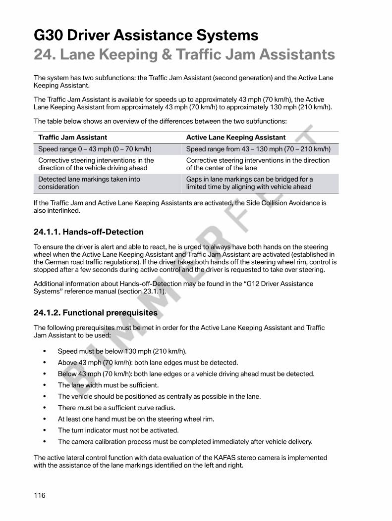
G30�Driver�Assistance�Systems24.�Lane�Keeping�&�Traffic�Jam�Assistants
116
The�system�has�two�subfunctions:�the�Traffic�Jam�Assistant�(second�generation)�and�the�Active�LaneKeeping�Assistant.
The�Traffic�Jam�Assistant�is�available�for�speeds�up�to�approximately�43�mph�(70 km/h),�the�ActiveLane�Keeping�Assistant�from�approximately�43�mph�(70 km/h)�to�approximately�130�mph�(210 km/h).
The�table�below�shows�an�overview�of�the�differences�between�the�two�subfunctions:
Traffic�Jam�Assistant Active�Lane�Keeping�AssistantSpeed�range�0�–�43�mph�(0�–�70 km/h) Speed�range�from�43�–�130�mph�(70 –�210 km/h)Corrective�steering�interventions�in�thedirection�of�the�vehicle�driving�ahead
Corrective�steering�interventions�in�the�directionof�the�center�of�the�lane
Detected�lane�markings�taken�intoconsideration
Gaps�in�lane�markings�can�be�bridged�for�alimited�time�by�aligning�with�vehicle�ahead
If�the�Traffic�Jam�and�Active�Lane�Keeping�Assistants�are�activated,�the�Side�Collision�Avoidance�isalso�interlinked.
24.1.1.�Hands-off-DetectionTo�ensure�the�driver�is�alert�and�able�to�react,�he�is�urged�to�always�have�both�hands�on�the�steeringwheel�when�the�Active�Lane�Keeping�Assistant�and�Traffic�Jam�Assistant�are�activated�(established�inthe�German�road�traffic�regulations).�If�the�driver�takes�both�hands�off�the�steering�wheel�rim,�control�isstopped�after�a�few�seconds�during�active�control�and�the�driver�is�requested�to�take�over�steering.
Additional�information�about�Hands-off-Detection�may�be�found�in�the�“G12�Driver�AssistanceSystems”�reference�manual�(section�23.1.1).
24.1.2.�Functional�prerequisitesThe�following�prerequisites�must�be�met�in�order�for�the�Active�Lane�Keeping�Assistant�and�TrafficJam�Assistant�to�be�used:
• Speed�must�be�below�130�mph�(210 km/h).• Above�43�mph�(70 km/h):�both�lane�edges�must�be�detected.• Below�43�mph�(70 km/h):�both�lane�edges�or�a�vehicle�driving�ahead�must�be�detected.• The�lane�width�must�be�sufficient.• The�vehicle�should�be�positioned�as�centrally�as�possible�in�the�lane.• There�must�be�a�sufficient�curve�radius.• At�least�one�hand�must�be�on�the�steering�wheel�rim.• The�turn�indicator�must�not�be�activated.• The�camera�calibration�process�must�be�completed�immediately�after�vehicle�delivery.
The�active�lateral�control�function�with�data�evaluation�of�the�KAFAS�stereo�camera�is�implementedwith�the�assistance�of�the�lane�markings�identified�on�the�left�and�right.

G30�Driver�Assistance�Systems24.�Lane�Keeping�&�Traffic�Jam�Assistants
117
In�order�for�the�system�to�be�activated,�two�lane�boundary�lines�must�be�detected.�Below�a�speed�ofapproximately�43�mph�(70 km/h)�a�vehicle�driving�ahead�in�the�same�lane�is�sufficient�to�activate�thesystem.
The�system�is�put�in�Standby�mode�if�the�marginal�conditions�are�not�satisfied�(e.g.�hands�not�onsteering�wheel,�lane�too�narrow�or�dazzling�of�KAFAS�stereo�camera).�Once�all�marginal�conditionshave�been�met,�the�system�is�re-enabled�automatically.
To�activate�the�system,�the�speed�of�the�vehicle�is�another�input�quantity�that�is�evaluated.�The�systemuses�these�values�to�decide�which�function�will�be�enabled.�As�mentioned�above,�the�threshold�valuesare�set�as�follows:
• The�Traffic�Jam�Assistant�can�be�enabled�within�a�speed�range�of�0�to�approximately�43�mph(70 km/h).
• The�Active�Lane�Keeping�Assistant�can�be�enabled�within�a�speed�range�from�approximately43�to�approximately�130�mph�(70 to�approximately�210 km/h).
24.1.3.�Lane�changeFor�a�lane�change�to�be�as�comfortable�as�possible,�the�Active�Lane�Keeping�Assistant�and�Traffic�JamAssistant�are�put�silently�into�Standby�mode�when�the�turn�indicator�is�activated�and�reactivates�itselfautomatically�once�the�turn�indicator�is�back�in�its�initial�position�and�a�lane�change�has�occurred.
24.1.4.�Function�logicThe�main�function�logic�of�the�lateral�guidance�is�implemented�in�the�Optional�Equipment�System(SAS)�control�unit.
The�majority�of�the�data�for�the�function�is�provided�by�the�KAFAS�stereo�camera,�where�algorithms�forthe�lane�and�object�detection�run.
Vehicle�dynamics�data,�such�as�the�driving�speed,�wheel�speeds,�yaw�rate,�steering�angle,�lateralacceleration,�longitudinal�acceleration,�etc.,�is�provided�by�the�rest�of�the�vehicle�network�via�a�FlexRayor�CAN�connection.
A�target�trajectory�(also�known�as�a�path�curve)�is�calculated�in�the�Optional�Equipment�System�(SAS)control�unit.�This�is�used�to�determine�whether�a�steering�correction�is�required.

G30�Driver�Assistance�Systems24.�Lane�Keeping�&�Traffic�Jam�Assistants
118
24.1.5.�Steering�interventionsIf�the�current�course�of�the�vehicle�deviates�too�much�from�the�target�trajectory�(path�curve),�a�steeringcorrection�is�initiated.
The�steering�intervention�is�a�corrective�measure.�This�means�the�driver�is�not�relieved�of�his�duty�tosteer�the�vehicle.�As�the�corrective�steering�interventions�are�limited�to�approximately�1.5 m/s²�basedon�the�lateral�acceleration,�the�system�cannot�navigate�curves�above�the�respective�speed-dependentcurve�radius�without�the�driver's�assistance.�The�driver�must�therefore�steer�the�vehicle�at�the�sametime�in�order�to�stay�on�the�roadway.
The�target�trajectory�and�required�steering�corrections�are�calculated�based�on�the�driving�speed�asfollows:
Speed�range�0�to�43�mph�(0�to�70 km/h):
• The�position�and�previous�movements�of�the�vehicle�driving�ahead�are�given�priority�whendetermining�the�appropriate�steering�corrections.
• Detected�lane�markings�are�taken�into�account�to�avoid�unwanted�steering�corrections�thatwould�result�in�leaving�the�lane.
• Corrective�steering�interventions�in�the�direction�of�the�center�of�the�lane�are�initiated�if�thevehicle�detects�there�is�not�a�vehicle�driving�ahead.
Speed�range�43�to�80�mph�(70 km/h�to�130 km/h):
• Corrective�steering�interventions�in�the�direction�of�the�center�of�the�lane�are�initiated.• It�is�possible�to�bridge�the�gap�for�a�limited�time�where�lane�markings�are�not�detected�by
estimating�the�course�of�the�lane�based�on�the�vehicle�driving�ahead.
Speed�range�80�to�130�mph�(130 km/h�to�210 km/h):
• Corrective�steering�interventions�in�the�direction�of�the�center�of�the�lane�are�initiated.• For�safety�reasons�above�a�driving�speed�of�approximately�80�mph�(130 km/h)�the�course�of
the�lane�is�not�estimated�using�the�vehicle�driving�ahead.
The�vehicle�driving�ahead�is�given�priority�as�the�"correction�target"�at�speeds�up�to�approximately�43mph�(70 km/h)�due�to�the�limited�detection�of�lane�markings.
In�traffic�jams�or�slow-moving�traffic�following�distances�are�often�extremely�small�(<�30�ft�(< 10 m))�dueto�tailgating�and�lanes�ahead�are�often�partially�covered�due�to�staggered�driving.
This�means�the�KAFAS�stereo�camera�is�unable�to�correctly�interpret�the�lane�markings�in�some�cases.
When�classifying�the�object�driving�ahead,�vehicles�such�as�motorbikes�are�not�used�as�the�"correctiontarget".

G30�Driver�Assistance�Systems24.�Lane�Keeping�&�Traffic�Jam�Assistants
119
Steering�momentum
The�driving�dynamics�function�software�in�the�Dynamic�Stability�Control�(DSC)�control�unit�calculates�atarget�steering�torque�based�on�the�curve�nominal�value.�The�target�steering�torque�is�then�convertedto�an�engine�torque�by�the�Electronic�Power�Steering�(EPS),�which�finally�results�in�a�steering�wheelmovement�at�the�wheels.
The�maximum�steering�torque�has�been�set�in�such�a�way�that�it�can�always�be�overruled�by�the�driverand�therefore�steering�past�the�maximum�steering�torque�is�possible.
24.1.6.�OperationThe�system�is�switched�on�via�the�Traffic�Jam�Assistant�button�on�the�multifunction�steering�wheel(MFL).
G30�buttons�for�ACC Stop&Go�with�Active�Driving�Assistant�Plus�optional�equipment�(OE�5AT)
Index Explanation1 Button�for�activating�or�deactivating�the�Active
Lane�Keeping�Assistant�and�Traffic�Jam�Assistant2 Button�for�activating�or�deactivating�ACC�Stop&Go3 Rocker�switch�for�changing�the�set�speed4 “SET”�button�for�setting�the�speed�of�cruise�control5 Button�for�adjusting�the�distance�of�the�driver's�vehicle�to
the�vehicle�driving�ahead6 Button�for�calling�up�a�saved�set�speed/temporarily�switching
off�the�cruise�control

G30�Driver�Assistance�Systems24.�Lane�Keeping�&�Traffic�Jam�Assistants
120
Displays
Symbols ExplanationGrey�steering�wheel�symbol:
• The�system�has�been�interrupted�andwill�not�make�any�further�steering�wheelmovements.�The�system�is�in�Standbymode.
• Once�the�system�conditions�aremet,�the�system�reactivates�itselfautomatically.
Green�steering�wheel�symbol�and�lane�edges:
• The�system�assists�in�keeping�thevehicle�in�the�lane.
Green�steering�wheel�symbol,�grey�lane�edges:
• No�lane�edges�detected.�The�vehiclefollows�the�vehicle�driving�ahead.
Yellow�steering�wheel�symbol:
• Request�for�driver�to�place�hands�backon�the�steering�wheel�(grasp�steeringwheel).�System�continues�to�be�active.
Red�steering�wheel�symbol�and�acoustic�signalsounds:
• The�system�has�been�interrupted.�It�willnot�make�any�further�steering�wheelmovements.
Configuration�options
The�driver�can�change�the�system�settings�in�the�Intelligent�Safety�configuration�menu.

G30�Driver�Assistance�Systems24.�Lane�Keeping�&�Traffic�Jam�Assistants
121
24.1.7.�Deactivation�criteriaThe�Active�Lane�Keeping�Assistant�and�Traffic�Jam�Assistant�is�deactivated�automaticallyin�the�following�situations:
• If�the�vehicle�departs�from�the�detected�lane�or�the�lane�width�does�not�meet�therequirements.
• If�the�lane�edges�of�the�current�lane�are�not�detected�by�the�KAFAS�stereo�camera.• If�no�vehicle�driving�ahead�is�detected.• The�vehicle�is�travelling�at�a�speed�greater�than�130�mph�(210 km/h).• If�the�Hands-off-Detection�cannot�detect�the�hands�(at�least�one�hand)�on�the�steering�wheel
rim.�The�system�is�switched�off�once�a�defined�time�threshold�(several�seconds)�has�elapsed.• Due�to�the�radius�of�the�bend�in�the�road,�the�inner�lane�edge�is�no�longer�detected�due�to�the
camera�aperture�angle.• Pedestrian�protection�assumes�the�operating�condition�"Fault�exists".• If�the�turn�indicator�is�on.• The�driver�intervenes�actively�in�the�steering.• If�over�a�certain�time�period�no�lane�edges�are�detected�and�there�is�not�a�vehicle
driving�ahead.• If�the�driver�manually�deactivates�the�DSC�(DSC�off).• If�there�is�an�intervention�from�the�preventative�pedestrian�protection.• After�Dynamic�Brake�Control�braking�(brake�assistant).
24.1.8.�Limits�of�the�systemWhen�driving�in�narrow�lanes,�e.g.�when�driving�through�construction�zones�or�when�emergency�lanesare�formed,�the�system�cannot�be�activated�or�used�meaningfully.
Due�to�the�limited�detection�capacity�of�the�KAFAS�stereo�camera,�the�driver�must�remain�alert�andobservant�in�order�to�be�able�to�actively�intervene�at�any�time�so�as�to�avoid�the�risk�of�an�accident.The�system�does�not�relieve�the�driver�of�personal�responsibility�for�correctly�judging�the�trafficsituation.�The�driver�is�solely�responsible�for�the�vehicle.

G30�Driver�Assistance�Systems25.�Active�Lane�Keeping�Assistant
122
The�Active�Lane�Keeping�Assistant�with�Side�Collision�Avoidance�is�part�of�the�Active�DrivingAssistant�Plus,�optional�equipment�(OE�5AT).
By�making�corrective�steering�interventions,�the�system,�already�familiar�from�the�G12�helps�the�driverto�keep�the�vehicle�in�lane�at�speeds�from�approximately�43�mph�(70 km/h)�to�approximately�130�mph(210 km/h)�and�to�actively�avoid�potential�side�collisions.�The�system�endeavors�to�orient�the�vehicle�inits�lane�according�to�the�situation�and�within�the�framework�of�the�system�limits.
The�system�consists�of�the�following�four�subfunctions:
• Side�Collision�Avoidance• Reduced�Side�Collision�Avoidance• Lane�Departure�Warning• Blind�Spot�Detection
25.1.�Side�Collision�AvoidanceThe�table�below�shows�an�overview�of�the�functional�characteristics�of�the�"Side�Collision�Avoidance"subfunction:
Speed�range Warning�functions Corrective�steering�intervention43�–�130�mph�(70 �–210 km/h)
• Issued�if�the�vehicledetects�that�it�is�gettingcritically�close�toanother�vehicle�to�theside
• Haptic�warning�in�theform�of�vibration�in�thesteering�wheel�using�anunbalanced�actuator
• Visual�warning�inexterior�mirror�inthe�form�of�thecorresponding�warninglight
• Corrective�steeringintervention�in�the�directionof�the�available�space�on�theroadway
Requirements:
• Detected�lanes• Sufficient�available�space
on�the�roadway
25.1.1.�Reduced�Side�Collision�AvoidanceThe�Reduced�Side�Collision�Avoidance�comes�into�play�if�it�is�not�possible�to�adequately�monitor�theavailable�space�on�the�roadway�or�there�is�no�available�space�on�the�roadway.
The�Reduced�Side�Collision�Avoidance�is�interlinked�with�the�Active�Lane�Keeping�Assistant�andTraffic�Jam�Assistant�functions.

G30�Driver�Assistance�Systems25.�Active�Lane�Keeping�Assistant
123
The�table�below�shows�an�overview�of�the�functional�characteristics�of�the�"Reduced�Side�CollisionAvoidance"�subfunction:
Speed�range Warning�functions Corrective�steering�intervention18�–�130�mph(30�–�210 km/h)
• Issued�if�the�vehicledetects�that�it�is�gettingcritically�close�toanother�vehicle�tothe�side
• Haptic�warning�in�theform�of�vibration�in�thesteering�wheel�using�anunbalanced�actuator
• Visual�warning�inexterior�mirror�inthe�form�of�thecorrespondingwarning�light
• 18�–�46�mph�(30�–75 km/h)�additionalwarning�in�form�ofsingle�steering�wheelpulse
• A�corrective�steeringintervention�is�not�initiated;instead�only�a�singlesteering�wheel�pulsewarning�is�issued�in�theopposite�direction�to�thedetected�object�the�vehiclecould�collide�with.
25.2.�Lane�Departure�WarningThe�table�below�shows�an�overview�of�the�functional�characteristics�of�the�"Lane�Departure�Warning"subfunction:
Speed�range Warning�functions Corrective�steering�intervention43�–�130�mph(70�–�210 km/h)
• Triggered�if�a�lanedeparture�is�detectedby�the�Lane�DepartureWarning�function.The�associated�hapticwarning�in�the�formof�a�vibration�in�thesteering�wheel�usingan�unbalanced�actuatoris�issued�and�visualwarning�in�the�exteriormirror�in�the�form�of�thecorresponding�warninglight.
• Corrective�steeringintervention�in�the�directionof�the�original�lane�if�vehiclemoves�towards�neighboringlane
Requirements:
• Detected�lanes

124
G30 Driver Assistance Systems25. Active Lane Keeping Assistant25.3. Blind Spot DetectionThe table below shows an overview of the functional characteristics of the "Blind Spot Detection"subfunction:
Speed range Warning functions Corrective steering intervention43 – 130 mph (70 – 210 km/h)
Prerequisites:
Further information can be found in the system descriptions of the respective subfunctions (seesection 8–10).
The Active Lane Keeping Assistant with Side Collision Avoidance does not relieve the driver of hisoverall responsibility for driving the vehicle. Due to the system limits be attentive in order to be able toactively intervene at any time. Otherwise, there is a risk of an accident.
• Triggered if a lanechange that couldresult in a collisionis detected by theBlind Spot Detectionfunction. Theassociated hapticwarning in the formof a vibration inthe steering wheelusing an unbalancedactuator is issuedand visual warningin the exterior mirrorin the form of thecorresponding warninglight.
• Corrective steeringintervention in the directionof the available space onthe roadway when lanechange intention is madeand neighboring lane isobstructed
• Detected lanes• Sufficient available space
on the roadway

G30�Driver�Assistance�Systems26.�Evasion�Aid
125
Often�a�collision�with�another�vehicle�(at�the�end�of�a�traffic�jam�for�example)�or�obstacle�can�onlybe�prevented�by�an�avoidance�maneuver.�Since�the�driver's�response�time�plays�a�decisive�role�inan�avoidance�maneuver�just�as�in�a�braking�maneuver,�Evasion�Aid�is�able�to�make�a�considerablecontribution�to�avoiding�an�impending�collision.
Evasion�Aid�supports�the�driver�in�such�critical�driving�situations�with�a�focused�steering�interventionif�the�driver�needs�to�avoid�an�obstacle.�The�system�also�help�keep�the�vehicle�stable�during�and�afterthe�avoidance�maneuver.
This�is�achieved�by�an�interaction�between�the�Dynamic�Stability�Control�(DSC),�the�Electronic�PowerSteering�(EPS)�and�the�analysis�of�data�from�the�assistance�sensors.
G30�Evasion�Aid:�interaction�of�Dynamic�Stability�Control(�DSC)�and�Electronic�Power�Steering�(EPS)
Evasion�Aid�is�a�function�of�the�Active�Driving�Assistant�Plus,�optional�equipment�(OE�5AT),�and�isfitted�in�the�G30�for�the�first�time.
26.1.�Functional�principleAn�emergency�avoidance�maneuver�takes�place�when�a�suddenly�occurring�obstacle�is�detected�infront�of�the�vehicle�and�the�driver�has�to�avoid�this�obstacle�quickly�and�without�“significant”�braking.
Evasion�Aid�supports�the�driver�in�avoidance�maneuvers�in�emergency�situations�and�calculates�anoptimum�“escape�track”�past�the�obstacle.
The�“escape�track”�is�calculated�within�the�physical�limits�of�the�particular�vehicle.�The�calculated“escape�track”�is�designed�to�minimize�transverse�dynamics.

G30�Driver�Assistance�Systems26.�Evasion�Aid
126
G30�Evasion�Aid
The�vehicle�is�preconditioned�before�an�anticipated�avoidance�maneuver.
Here�all�functions�that�contribute�to�stabilize�the�vehicle�are�adapted�in�their�configuration�for�themaximum�support�of�the�driver.�This�can�reduce�the�risk�of�unstable�vehicle�behavior�or�overloading�thedriver�in�an�acute�avoidance�maneuver.
Evasion�Aid�checks�the�current�vehicle�inclination�and�the�driver's�steering�wheel�actions�andcompares�the�information�with�the�computed�“escape�track”.�Should�the�system�detect�discrepancies,an�appropriate�steering�intervention�is�applied�to�steer�the�vehicle�to�the�previously�estimated�“escapetrack”.
The�design�objective�for�the�system�was�that�the�driver's�selected�steering�is�not�bypassed,�butinstead�the�feel�of�the�steering�wheel�use�is�modified.�The�driver�is�supported�by�an�additional�supporttorque�in�the�Electronic�Power�Steering�(EPS)�for�the�avoidance�maneuver.
If�a�collision-threatening�situation�is�detected�and�an�acute�warning�has�been�issued,�Evasion�Aidevaluates�the�traffic�situation.

G30�Driver�Assistance�Systems26.�Evasion�Aid
127
The�possible�free�space�for�an�avoidance�maneuver�is�analyzed�on�the�basis�of�this�critical�situation.Radar�sensors�and�the�KAFAS�stereo�camera�monitor�the�vehicle's�surroundings.�The�system�canintervene�to�provide�support�if�an�avoidance�opportunity�next�to�the�vehicle�in�front�is�available�and�ifno�collision�object�has�been�detected�to�the�side�of�the�own�vehicle.
The�system�assists�the�driver�in�the�speed�range�from�25�–�100�mph�(40�to�160 km/h).
The�driver�initiates�the�avoidance�maneuver�by�turning�the�steering�wheel�rapidly,�at�the�same�timedetermining�the�avoiding�direction.�Any�brake�intervention�initiated�by�the�acute�warning�is�aborted�orsuppressed�as�appropriate.�The�Electronic�Power�Steering�(EPS)�implements�a�supporting�steeringintervention.
The�vehicle�is�made�“more�agile”�by�the�system�as�it�steers�around�the�obstacle�and�then�stabilizedagain�when�it�reaches�the�escape�lane.
Rapid�and�effective�avoidance�is�possible�thanks�to�the�vehicle's�improved�response�to�steeringcommands,�without�endangering�the�general�driving�stability.
G30�Evasion�Aid:�make�agile/stabilize
Index Explanation1 Make�agile2 Stabilize
The�hard�shoulder�may�be�used�as�the�escape�lane,�in�addition�to�a�normal�lane.
The�supporting�steering�intervention�by�the�system�is�not�performed�until�after�the�driver�has�activelyinitiated�the�avoidance�maneuver.�An�avoidance�maneuver�by�Evasion�Aid�alone�is�thus�not�performed.The�driver�must�likewise�determine�the�direction�of�the�avoidance.

G30�Driver�Assistance�Systems26.�Evasion�Aid
128
26.2.�System�overviewBelow�we�describe�which�main�components�or�sensors�are�relevant�to�Evasion�Aid.
• Object�or�obstacles�are�detected�by�means�of�the�KAFAS�stereo�camera�and�the�ACCStop&Go�front�radar�sensor.
• The�four�side�radar�sensors�monitor�the�area�around�the�vehicle.�The�data�from�the�KAFASstereo�camera�is�also�analyzed�and�in�this�way�a�possible�free�space�for�an�avoidancemaneuver�can�be�identified.
• A�target�trajectory�(also�known�as�a�path�curve),�that�is�the�“escape�track”�itself,�is�calculated�inthe�Optional�Equipment�System�(SAS)�control�unit.
• The�driving�dynamics�function�software�in�the�Dynamic�Stability�Control�(DSC)�control�unitcalculates�a�target�steering�torque�based�on�the�“escape�track”.
• The�target�steering�torque�is�converted�to�an�engine�torque�by�the�Electronic�Power�Steering(EPS),�which�finally�results�in�a�supporting�steering�intervention,�if�necessary.The�maximum�steering�torque�has�been�set�in�such�a�way�that�it�can�always�be�overruled�bythe�driver�and�therefore�steering�past�the�maximum�steering�torque�is�possible.

G30�Driver�Assistance�Systems26.�Evasion�Aid
129
G30�Evasion�Aid�system�overview
Index Explanation1 Control�unit�for�radar�sensor,�right�(RSR)2 KAFAS�stereo�camera3 Blind�Spot�Detection,�right�(primary)4 Blind�Spot�Detection,�left�(secondary)5 Optional�Equipment�System�(SAS)

G30�Driver�Assistance�Systems26.�Evasion�Aid
130
Index Explanation6 Dynamic�Stability�Control�(DSC)7 Control�unit�for�radar�sensor,�left�(RSL)8 Active�Cruise�Control�(ACC)9 Electronic�Power�Steering�(electromechanical�power�steering)�(EPS)
26.3.�OperationA�special�precondition�such�as�the�individual�configuration�capability�for�the�system�or�deactivation�ofthis�function�only�is�not�possible.
Evasion�Aid�can�only�be�deactivated�by�switching�off�all�Intelligent�Safety�systems�(ALL OFF).
The�system�does�not�relieve�the�driver�of�personal�responsibility�for�correctly�judging�the�trafficsituation.�The�driver�is�solely�responsible�for�the�vehicle.
26.4.�Functional�prerequisitesEvasion�Aid�is�not�linked�to�a�particular�road�type.
The�following�parameters�are�the�prerequisites�for�the�availability�of�Evasion�Aid:
• The�vehicle's�speed�must�not�be�below�approximately�25�mph�(40 km/h)�andbe�no�higher�than�approximately�100�(160 km/h).
• The�system�must�have�identified�a�free�space�for�an�avoidance�maneuver.
Evasion�Aid�is�generally�not�available�in�the�following�cases:
• The�vehicle's�speed�is�below�approximately�25�mph�(40 km/h)�or�higherthan�approximately�100�mph�(160 km/h).
• During�a�dynamic�overtaking�maneuver�initiated�by�the�driver.• If�the�Dynamic�Stability�Control�has�been�switched�off�by�the�driver,
or�there�is�a�fault�in�the�DSC.• When�all�Intelligent�Safety�systems�are�switched�off.• In�the�event�of�systemic�limitations�of�the�radar�sensors�or�the�KAFAS�stereo�camera.
G30�Driver�Assistance�Systems26.�Evasion�Aid
131
26.5.�Limits�of�the�systemThe�collision�warning�has�a�limited�capacity�for�detection.�As�a�result,�incorrect�or�delayed�warningsmay�occur�and�consequently�Evasion�Aid�is�limited�in�its�operation.�It�is�also�possible�that�the�followingvehicles�are�not�detected:
• A�slow�vehicle�when�driving�off�at�high�speed.• Vehicles�that�suddenly�swerve�or�decelerate�rapidly.• Vehicles�with�an�unusual�rear�view�or�with�insufficiently�visible�rear�lights.• Partially�concealed�vehicles.• Two-wheeled�vehicles�travelling�ahead.
The�function�of�the�KAFAS�stereo�camera�and�the�radar�sensors,�and�thus�the�function�of�Evasion�Aidmay�be�impaired�in�the�following�situations:
• Heavy�fog,�rain,�spray�or�snow.• Insufficient�light.• Strong�light�in�the�camera�lens.• If�the�field�of�view�of�the�KAFAS�stereo�camera�or�the�windscreen�is�dirty.• On�sharp�bends.• Up�to�10 seconds�after�engine�start�via�the�START-STOP�button.• On�restriction�or�deactivation�of�the�driving�dynamics�systems,�for�example�DSC�OFF.• During�the�calibration�process�for�the�KAFAS�stereo�camera�immediately�after�vehicle
delivery�or�a�camera�change.
Evasion�Aid�does�not�release�the�driver�from�his�comprehensive�responsibility�as�the�driver.�There�canbe�functional�limitations�because�of�system�restrictions.


