
Gantt chart analysis to improve shipbuilding panel line assembly
Author name(s): Damir Kolich(M), Vanda Brandic(SM), Doroteja Jaki(SM), Lino Novak(SM) University of Rijeka, Faculty of Engineering, Naval Architecture and Ocean Engineering Department, Rijeka, Croatia.
Over 60 percent of a typical commercial ships interim products consists of stiffened steel panels. Modern shipyards continually strive
to improve their assembly processes. The panel assembly line is one such process which lends itself well to automation in order to
reduce man-hours thereby, enabling profit to a shipyard. In this paper, Gantt chart analysis in compliance with a product work
breakdown structure (PWBS) methodology is used to map the process of the assembly of a typical panel from a self-unloading bulker
vessel. Then, through the combination of lean principles of reducing waste and the utilization of one-piece flow in complement with
adaptation of advanced hybrid laser arc welding technology, yields a new and improved panel assembly line proposal. The
improvements in the reduction of man-hours through Gantt chart analysis are found to be a significant 86%. This means that a
shipyard, by applying these changes could significantly cut its production costs, while maintaining or even improving the quality of its
interim products.
KEY WORDS: Gantt chart analysis, shipbuilding, Product work
breakdown structure (PWBS), lean principles, hybrid-laser arc
welding
INTRODUCTION
Gantt chart analysis is used in many industries. The shipbuilding
industry uses it extensively in most levels of its functional
analysis. However, whereas shipyard planning offices create
Gantt charts that show yearly, monthly and weekly plans, rarely
do shipyards have Gantt charts for each type of interim product
that is assembled in its premises. In this paper, the most
common interim product, a steel panel is analyzed using Gantt
chart analysis. This is in compliance with a product work
breakdown structure (PWBS) which has proven to be essential
in developing an efficient shipyard production system according
to the SNAME Design for Production (DFP) Manual (1999).
A functional system is based on analysis of different systems
throughout the ship and is very practical in the contract stage of
shipbuilding. For instance, for the development of the general
arrangement plan, the midship section, and outline
specifications which are used for price estimation of work,
materials and also includes a makers list. Once the contract is
signed, the shipyard designers start developing all of the
required classification society drawings. When the classification
drawings receive stamp approval, then the ship detail designers
prepare production drawings. The workers in the workshop are
exclusively interested in the detailed production drawings,
which define how, where and what to fabricate and assemble.
When a PWBS system is successfully integrated with these
production drawings, this allows for a very clear breakdown of
jobs and interim product development. Likewise, it is possible to
identify areas where production could be improved through
decreasing unnecessary bottlenecks and replacing outdated tools
and assembly methods with avante garde technology.
In this paper, the panel assembly line is analyzed utilizing the
proper PWBS method, which illustrates the breakdown of both
the assembly methods, the corresponding tools, technology, the
number of workers and the trade that they belong to. Then
through the use of lean principles, a new and better improved
panel assembly line is proposed and demonstrated to yield a
more efficient panel assembly system, which results in reduced
man-hours, thereby yielding increased savings for the shipyard.
BACKGROUND
The panel assembly line has been analyzed using value stream
analysis and lean terminology (Kolich et al 2015a, 2017a).
Likewise, the built up panel assembly was also analyzed using
value stream mapping (Kolich et al 2016, 2017b). The
conclusion is that value stream mapping helps identify losses
and through implementing lean methodologies, it is possible to
reap savings of up to 80 percent in panel assembly, 50 percent in
built-up panel assembly, and finally 50 percent in large erection
block assembly (Kolich et al 2017c). Whereas, value stream
mapping allows for a very efficient way of viewing the
assembly processes in a shipyard, the Gantt charts are able to
define more detail which will additionally help production
engineering to identify specific tasks that could be improved.
SHIPYARD PANEL ASSEMBLY CASE STUDY
The case analyzed in this paper is a typical shipyard panel of a
self-unloading bulk vessel with a length of 198 meters, a beam
of 23.77 meters and a deadweight of 24900 tons (See Figure 1).
Fig.1 200 m self-unloading bulk carrier vessel at 3. Maj
shipyard

Kolich, Brandic, Jaki, Novak Gantt chart analysis to improve shipbuilding panel line assembly 2
The typical panel is represented by an isometric view in Figure
2. It consists of four steel plates butt welded on both sides, along
with a total of nine longitudinal Holland profile stiffeners. The
total mass of the stiffened panel is 11255 kg (3. Maj 2015).
Fig.2 Panel P110
In Figure 3, there is a plan view of the Figure 2 panel, which
illustrates how many longitudinal profile stiffeners there are on
each plate. Since panel P110 is eventually transformed to a
built-up panel, this is why it is labelled as KP which is the
symbol for built-up panel in the shipyard analyzed in this paper.
Each steel plate has a workshop number. For instance the
numbers in squares represent the workshop numbers of each
steel plate, 184, 191, 200, and 207 respectively. The thickness of
each steel plate is 12.5 mm. Each longitudinal stiffener has its
own workshop number, 1727, 1726, 1730. Likewise,
consecutive numbers of all nine stiffeners from 1 to 9 are
embedded in a triangular symbol, which represents each
stiffener.
Fig.3 Panel KP11
In Figure 4 below is a plan view illustration of the panel
assembly line. There are four workstations plus the fifth
workstation which serves for interim storage before the panel is
transported to the built-up panel assembly line.
Fig.4 Panel assembly line
First workstation panel assembly
At the first workstation (Figure 5), the first steel plate
(workshop number 207) is placed and centered in place. Then
the second steel plate (workshop number 200) is placed and
centered alongside the first steel plate. The two steel plates are
tack welded by ship-fitters. Afterwards, the third steel plate
(number 191) is placed alongside steel plate number 200 and
tack welded to it. The fourth and final steel plate (workshop
number 184) is tack welded to steel plate number 191. This is all
demonstrated in the first 16 activities of workstation number 1
Gantt chart (See Figure 6). Since there are four steel plates that
means that there will be a total of three seam welds using
submerged arc welding technology located on the semi-
automated welding gantry. This is illustrated in the final five
activities of the first workstation. Five workers multiplied by 3.1
hours yields a total of 15,5 man-hours at this workstation.
Fig.5 Panel assembly line

Kolich, Brandic, Jaki, Novak Gantt chart analysis to improve shipbuilding panel line assembly 3
Fig.6 First Workstation Gantt chart
Second workstation panel assembly
At the second workstation, once the butt welded panel with four
steel plates gets transported to the second workstation along the
rollers, then it is connected to clamps on a crane and turned over
to the other side (See Figure 7). Then each seam is butt welded
on the other side one by using the same gantry crane fitted with
automatic submerged arc welding technology as was at
workstation number one. This can be viewed on the Gantt chart
in Figure 8. The duration time is a total of 2.83 hours. There are
a total of 5 workers which translates to 14.15 man-hours.
Fig.7 Panel assembly line
Fig.8 Second Workstation Gantt chart

Kolich, Brandic, Jaki, Novak Gantt chart analysis to improve shipbuilding panel line assembly 4
Third workstation panel assembly
The butt welded panel on both sides is now ready to be prepared
for tracing the positions of the nine stiffeners. In order for the
welds to be of acceptable quality and efficiently performed, it is
necessary to first grind down the positions of the longitudinal
stiffeners on the steel panel. This is because there is primer paint
which needs to be removed so that the longitudinal stiffeners
adhere better to the butt welded panel. In case this would not be
done, the welding would take longer and be of a poorer quality.
Therefore at this workstation, there are two operators who use
the grinding machines and two tracers who trace out the exact
positions of the longitudinal stiffeners. Since there are a total of
4 operators and the duration time is 2.83 hours, there is a total of
11.32 man-hours at this workstation. Figure 9 shows an
illustration of the grinding paper used at this workstation. Figure
10 shows the Gantt chart of the third workstation with all
relevant activities, duration times and corresponding trades.
Figure 9: Grinding paper
Fig.10 Third Workstation Gantt chart
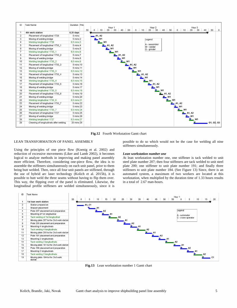
Fourth workstation
At the fourth workstation (Figure 11) each of the nine longitudinal
stiffeners are fitted one at a time. Then the welding bridge moves in
place and starts welding using submerged arc welding technology.
Since there are pins pressing down on the longitudinal stiffeners, it is
not necessary to tack weld as in the earlier assembly stations. The
welding is performed at a rate of 1500 mm per minute, which means
that a stiffener of 9800 mm length will take 6.5 minutes to weld. The
total duration time is 2.83 hours. There are four operators for a total of
11.32 man-hours. This is illustrated in detail by the Gantt chart of
workstation number 4 (See Figure 12).
Man-hours
At the first workstation there were 15.5 man-hours; 14.15 man-hours at
workstation number 2; 11.32 man-hours at workstation number three
and 11.32 man-hours at workstation 4 for a total of 52.3 man-hours for
the assembly of the panel in this case study. The total duration time
when the values of the corresponding workstations are summed up: 3.1,
2.83, 2.83 and 2.83 yields a total of 11.6 hours.
Figure 11: Welding Gantry for profiles at workstation number 4
Kolich, Brandic, Jaki, Novak Gantt chart analysis to improve shipbuilding panel line assembly 5
Fig.12 Fourth Workstation Gantt chart
LEAN TRANSFORMATION OF PANEL ASSEMBLY
Using the principles of one piece flow (Koenig et al. 2002) and
reduction of excessive movements (Liker and Lamb 2002), it becomes
logical to analyze methods in improving and making panel assembly
more efficient. Therefore, considering one-piece flow, the idea is to
assemble the stiffeners simultaneously on each unit panel, prior to them
being butt welded. Then, once all four unit panels are stiffened, through
the use of hybrid arc laser technology (Kolich et al. 2015b), it is
possible to butt weld the three seams without having to flip them over.
This way, the flipping over of the panel is eliminated. Likewise, the
longitudinal profile stiffeners are welded simultaneously, since it is
possible to do so which would not be the case for welding all nine
stiffeners simultaneously.
Lean workstation number one
At lean workstation number one, one stiffener is tack welded to unit
steel plate number 207; then four stiffeners are tack welded to unit steel
plate 200; one stiffener to unit plate number 191; and finally three
stiffeners to unit plate number 184. (See Figure 13) Since, there is an
automated system, a maximum of two workers are located at this
workstation, when multiplied by the duration time of 1.33 hours results
in a total of 2.67 man-hours.
Fig.13 Lean workstation number 1 Gantt chart

Kolich, Brandic, Jaki, Novak Gantt chart analysis to improve shipbuilding panel line assembly 6
Lean workstation number two
At this second lean workstation, the unit panel with tack-welded
stiffeners are now fully welded (See Figure 14). The duration time is
over one hour and 15 minutes or 1.25 hours. There are two workers
which when multiplied by the duration time of 1.25 hours yields a total
of 2.5 man-hours.
Fig.14 Lean workstation number 2 Gantt chart
Lean workstation number three
At workstation number three, the unit stiffened panels are then butt
welded using one-sided hybrid laser arc welding technology. It lasts 1.1
hours and since there are two workers at this station, there are also a
total of 2.2 man-hours. The total man-hours of the three lean
workstations by summing up 2.67, 2.5, 2.2 which yields a total of 7.37
man-hours. In comparison to the 52.3 man-hours of the classical panel
assembly line workstations, 7.37 man-hours represents an improvement
of 86% in man-hours. Since over 60 percent of ships interim products
are made up of straight panels, the savings in ship production costs
could be very significant The duration time of the classical panel
assembly line is 11.6 hours in comparison to (1.33+1.25+1.1) or 3.68
hours in the lean panel assembly line which represents 68% decrease in
duration time, which is likewise significant.
Fig.15 Lean workstation number 3 Gantt chart
CONCLUSIONS. The duration time of assembling one typical panel with nine stiffeners
on a classical panel assembly line is 11.6 hours. There are a total of
52.3 man-hours. The lean transformation utilizes laser arc welding and
one-piece flow. This in turn yields simultaneous fitting and welding of
multiple longitudinal stiffeners, up to four pieces simultaneously to unit
plates. The stiffened unit plates are then welded using one-sided hybrid
laser arc welding technology which is faster and does not require the
panel butt seams to be welded on the other side. Therefore, there are
significant savings in duration time of 68% and man-hours of 86%. The
argument for transforming classical shipbuilding processes into lean
ones is very strong and requires understanding and mapping the present
system, and by applying lean principles and appropriate technologies
thereby creating a transformed and significantly improved system. This
means that shipyards that are presently non-competitive in the
international shipbuilding market can become competitive and compete
with world-class shipyards both in price and quality.
REFERENCES
Koenig, P. C., Narita, H. and Baba, K. 2002 Lean Production in
the Japanese Shipbuilding Industry?, Journal of Ship
Production 18,3, 167-174.
.
Kolich,D., Storch, R.L., Fafandjel, N. 2015a Optimizing
shipyard interim product assembly using a value stream
mapping methodology, Proceedings, World Maritime
Technology Conference Papers Society of Naval
Architects and Marine Engineers, November 3-7,
Rhode Island, 1-10.
Kolich, D., Yao, Y.L., Neuberg, R., Storch, R.L. and Fafandjel,
N. 2015b Data mining to predict hybrid laser arc
welding improvements in ship interim product
assembly, Proceedings, The International Conference
of Computer Applications in Shipbuilding, Royal
Kolich, Brandic, Jaki, Novak Gantt chart analysis to improve shipbuilding panel line assembly 7
Institute of Naval Architects, September 29 – October
2, Bremen, 137-168.
Kolich,D., Storch, R.L., Fafandjel, N. 2016 Lean transformation
of built-up panel assembly in shipbuilding using a
value stream mapping methodology, Proceedings,
SNAME Maritime Conference Papers Society of Naval
Architects and Marine Engineers, November 1-5,
Bellevue, Washington, 1-10.
Kolich,D., Storch, R.L., Fafandjel, N. 2017a Lean methodology
to transform shipbuilding panel assembly, Journal of
Ship Production and Design, 33, 4, 317-326.
Kolich,D., Storch, R.L., Fafandjel, N. 2017b Lean built-up panel
assembly in a newbuilding shipyard, Journal of Ship
Production and Design, 0, 0, 1-9.
Kolich,D., Storch, R.L., Fafandjel, N. 2017c Lean IHOP
transformation of shipyard erection block construction,
Proceedings, SNAME Maritime Convention Papers,
Society of Naval Architects and Marine Engineers,
October 24-28, Houston.
Liker, J. K. and Lamb, T. 2002 What is Lean Ship Construction
and Repair?. Journal of Ship Production, 18, 3, 121-
142.
3. Maj. 2017 Shipyard Archive, Rijeka, Croatia
SNAME Design for Production Manual. 1999 Design for
Production Manual, 2nd edition, Bethesda MD: Naval
Surface Warfare Center, National Shipbuilding
Research Program, U.S. Department of the Navy
Carderock Division, Vol. 1-3.
AUTHOR BIOGRAPHIES
Prof. Damir Kolich, PhD., Nav. Arch., is an assistant professor
at the Faculty of Engineering, University of Rijeka. He
is a member of SNAME since 1992 and was graduated
from Webb Institute in New York in 1996. After
working in the sales and design departments of various
Croatian shipyards, he enrolled in the University of
Rijeka Naval Architecture Department as a Teaching
Assistant in 2008, where he earned his PhD in 2011.
His specialties are lean manufacturing, design for
production and data mining in shipbuilding. He is the
Faculty Head of the SNAME student chapter at the
University of Rijeka, and actively works with the
parent Greek section of SNAME. He also assists the
student “RITEH Waterbike Team”.
Vanda Brandic, Univ. Bacc. Ing. Nav. Arch. earned her
bachelor’s degree in 2016 from the Faculty of
Engineering, University of Rijeka, and is presently
enrolled in the second and final year of the Master’s
Degree program in Naval Architecture and Ocean
Engineering. She presented the paper “PWBS Best
Practice Analysis of Two Shipyards” at the Seventh
Conference on Marine Technology - Winkler in
November, 2017, which received high acclaim from
top shipyard management. and is also Vice-
Chairperson of the first SNAME Student section in
Croatia; a very active member who among many other
things prepared the SNAME student By-Laws for the
University of Rijeka.
Doroteja Jaki, Univ. Bacc. Ing. Nav. Arch. earned her
bachelor’s degree in 2017 from the Faculty of
Engineering, University of Rijeka, and is presently
enrolled in the second and final year of the Master’s
Degree program in Naval Architecture and Ocean
Engineering. She is the Secretary/Treasurer of the first
SNAME Student Section in Croatia. Involved in a
plethora of SNAME activities, she significantly
contributes to the promulgation of the SNAME student
chapter at the University of Rijeka, such as Poster
development and expert advice.
Josip Lino Novak, Univ. Bacc. Ing. Nav. Arch. earned his
bachelor’s degree in 2016 from the Faculty of
Engineering, University of Rijeka, and is presently
enrolled in the second and final year of the Master’s

Kolich, Brandic, Jaki, Novak Gantt chart analysis to improve shipbuilding panel line assembly 8
Degree program in Naval Architecture and Ocean
Engineering at the University of Rijeka. As
Chairperson of the first SNAME Student section in
Croatia, he attended the SNAME Maritime Convention
held in Houston in 2017, where he networked with
other SNAME student members, especially with those
of the parent SNAME Greek section.


