Chapter 13
Gears
General
1/2/2015 2:04 PM
Dr. Mohammad Suliman Abuhaiba, PE 1
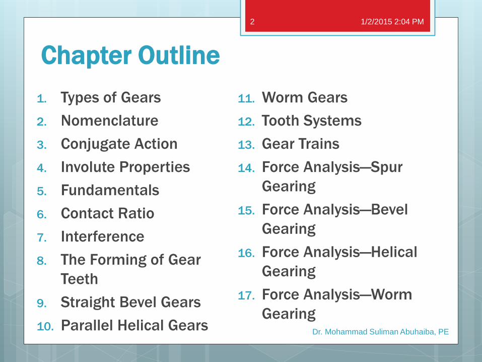
Chapter Outline
1. Types of Gears
2. Nomenclature
3. Conjugate Action
4. Involute Properties
5. Fundamentals
6. Contact Ratio
7. Interference
8. The Forming of Gear
Teeth
9. Straight Bevel Gears
10. Parallel Helical Gears
1/2/2015 2:04 PM
Dr. Mohammad Suliman Abuhaiba, PE
2
11. Worm Gears
12. Tooth Systems
13. Gear Trains
14. Force Analysis—Spur
Gearing
15. Force Analysis—Bevel
Gearing
16. Force Analysis—Helical
Gearing
17. Force Analysis—Worm
Gearing
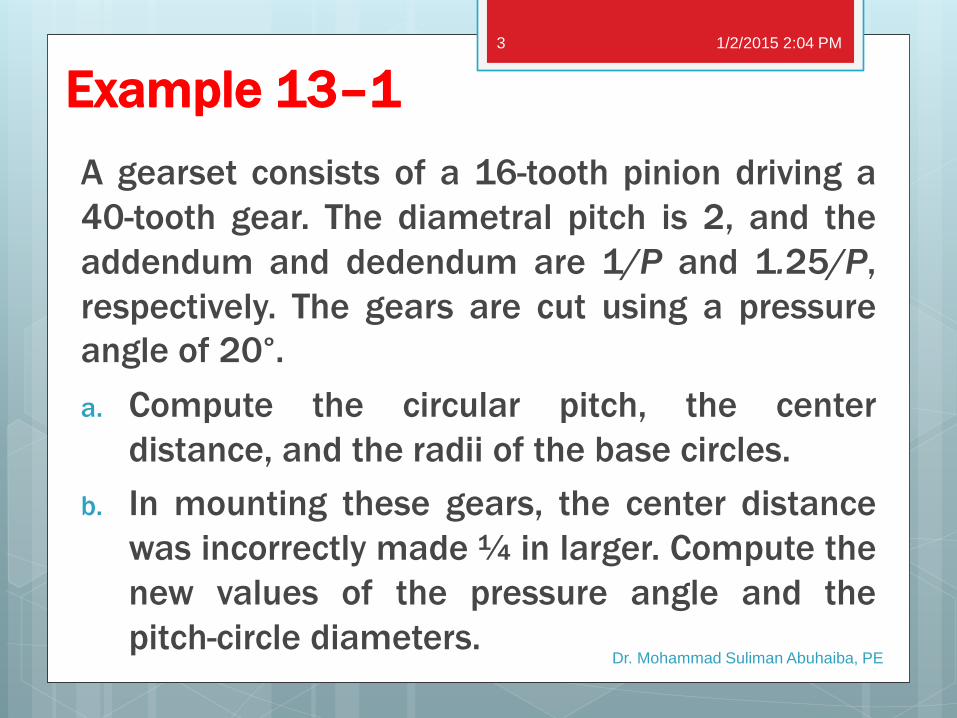
Example 13–1
A gearset consists of a 16-tooth pinion driving a
40-tooth gear. The diametral pitch is 2, and the
addendum and dedendum are 1/P and 1.25/P,
respectively. The gears are cut using a pressure
angle of 20°.
a. Compute the circular pitch, the center
distance, and the radii of the base circles.
b. In mounting these gears, the center distance
was incorrectly made ¼ in larger. Compute the
new values of the pressure angle and the
pitch-circle diameters.
1/2/2015 2:04 PM
Dr. Mohammad Suliman Abuhaiba, PE
3

13–9 Straight Bevel Gears
Figure 13–20
Terminology of bevel
gears
Pitch of bevel gears is
measured at the large
end of tooth
Both the circular pitch
and the pitch diameter
are calculated in the
same manner as for
spur gears
1/2/2015 2:04 PM
Dr. Mohammad Suliman Abuhaiba, PE
4

13–9 Straight Bevel Gears
Shape of the teeth,
when projected on back
cone, is the same as in
a spur gear having a
radius equal to the
back-cone distance rb.
The number of teeth in
this imaginary gear is
1/2/2015 2:04 PM
Dr. Mohammad Suliman Abuhaiba, PE
5

13–10 Parallel Helical Gears
Used to transmit motion between parallel shafts
Helix angle is the same on each gear, one gear must
have a RH helix and the other a LH helix.
The shape of the tooth is an involute helicoid (Fig. 13–
21).
1/2/2015 2:04 PM
Dr. Mohammad Suliman Abuhaiba, PE
6

spur-gear helical-gear
line contact extending
all the way across face
of tooth
Initial contact of teeth is a point
that extends into a line as teeth
come into more engagement.
line of contact is parallel
to axis of rotation
line is diagonal across face of
tooth.
gradual engagement of teeth and
smooth transfer of load from one
tooth to another that gives helical
gears the ability to transmit
heavy loads at high speeds.
13–10 Parallel Helical Gears
1/2/2015 2:04 PM
Dr. Mohammad Suliman Abuhaiba, PE
7

13–10 Parallel
Helical Gears
Figure 13–22: a portion of
top view of a helical rack
ab & cd: centerlines of two
adjacent helical teeth taken
on the same pitch plane
ψ = helix angle
ac = transverse circular pitch
pt in the plane of rotation
(circular pitch)
ae = normal circular pitch
1/2/2015 2:04 PM
Dr. Mohammad Suliman Abuhaiba, PE
8
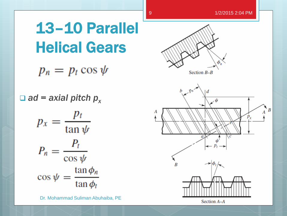
13–10 Parallel
Helical Gears
ad = axial pitch px
1/2/2015 2:04 PM
Dr. Mohammad Suliman Abuhaiba, PE
9
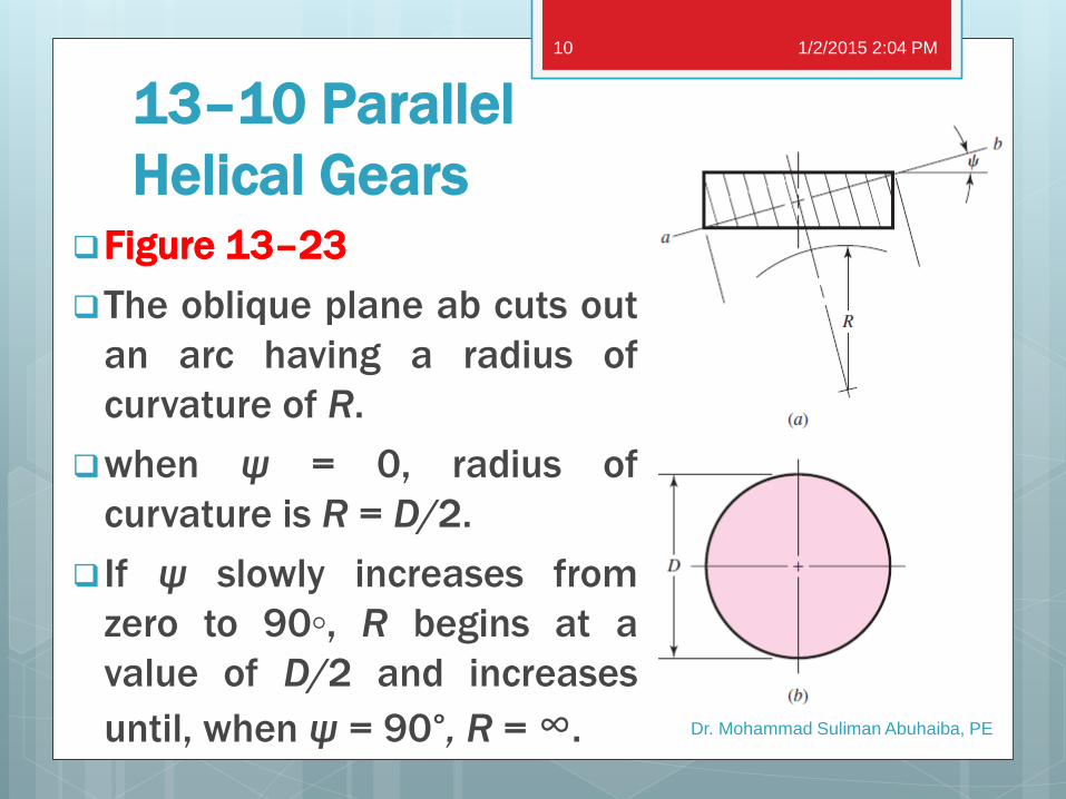
13–10 Parallel
Helical Gears Figure 13–23
The oblique plane ab cuts out
an arc having a radius of
curvature of R.
when ψ = 0, radius of
curvature is R = D/2.
If ψ slowly increases from
zero to 90◦, R begins at a
value of D/2 and increases
until, when ψ = 90°, R = ∞.
1/2/2015 2:04 PM
Dr. Mohammad Suliman Abuhaiba, PE
10

13–10 Parallel Helical Gears
R = apparent pitch radius of a
helical gear tooth when viewed in
direction of the tooth elements.
A gear of same pitch and with
radius R will have a greater
number of teeth, because of
increased radius.
In helical-gear terminology this is
called the virtual number of teeth.
1/2/2015 2:04 PM
Dr. Mohammad Suliman Abuhaiba, PE
11
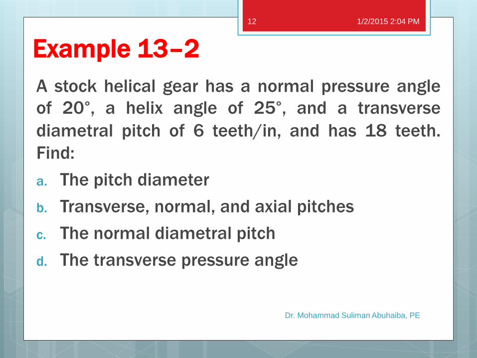
Example 13–2
A stock helical gear has a normal pressure angle
of 20°, a helix angle of 25°, and a transverse
diametral pitch of 6 teeth/in, and has 18 teeth.
Find:
a. The pitch diameter
b. Transverse, normal, and axial pitches
c. The normal diametral pitch
d. The transverse pressure angle
1/2/2015 2:04 PM
Dr. Mohammad Suliman Abuhaiba, PE
12
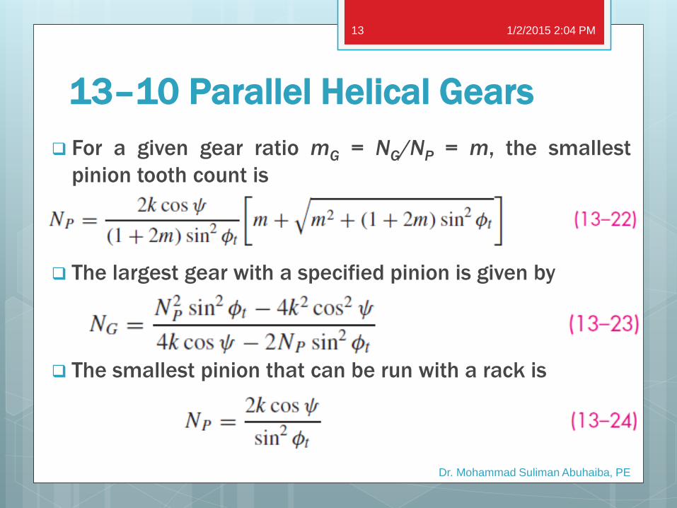
13–10 Parallel Helical Gears
For a given gear ratio mG = NG/NP = m, the smallest
pinion tooth count is
The largest gear with a specified pinion is given by
The smallest pinion that can be run with a rack is
1/2/2015 2:04 PM
Dr. Mohammad Suliman Abuhaiba, PE
13
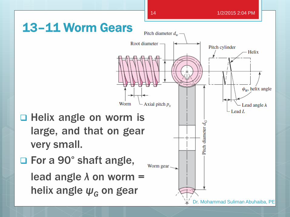
13–11 Worm Gears
Helix angle on worm is
large, and that on gear
very small.
For a 90° shaft angle,
lead angle λ on worm =
helix angle ψG on gear
1/2/2015 2:04 PM
Dr. Mohammad Suliman Abuhaiba, PE
14

Axial pitch px of worm = transverse circular pitch
pt of mating gear if shaft angle is 90°
Pitch diameter of gear = diameter measured on
a plane containing the worm axis,
Pitch diameter of worm should be selected so as
to fall into the range
13–11 Worm Gears
1/2/2015 2:04 PM
Dr. Mohammad Suliman Abuhaiba, PE
15

Lead L & lead angle λ of worm have the
following relations:
13–11 Worm Gears
1/2/2015 2:04 PM
Dr. Mohammad Suliman Abuhaiba, PE
16

13–12 Tooth Systems
Table 13–1: Standard & Commonly Used
Tooth Systems for Spur Gears
1/2/2015 2:04 PM
Dr. Mohammad Suliman Abuhaiba, PE
17

13–12 Tooth Systems
Table 13–2: Tooth Sizes in General Uses
1/2/2015 2:04 PM
Dr. Mohammad Suliman Abuhaiba, PE
18

13–12 Tooth Systems Table 13–3: Tooth Proportions for 20° Straight Bevel-Gear Teeth
1/2/2015 2:04 PM
Dr. Mohammad Suliman Abuhaiba, PE
19

13–12 Tooth Systems Table 13–4: Standard Tooth Proportions for Helical Gears
1/2/2015 2:04 PM
Dr. Mohammad Suliman Abuhaiba, PE
20

13–12 Tooth Systems
Table 13–5: Recommended Pressure Angles and
Tooth Depths for Worm Gearing
1/2/2015 2:04 PM
Dr. Mohammad Suliman Abuhaiba, PE
21

13–13 Gear Trains
Figure 13–26: Thrust, rotation, and hand relations for
crossed helical gears
1/2/2015 2:04 PM
Dr. Mohammad Suliman Abuhaiba, PE
22

1/2/2015 2:04 PM
Dr. Mohammad Suliman Abuhaiba, PE
23
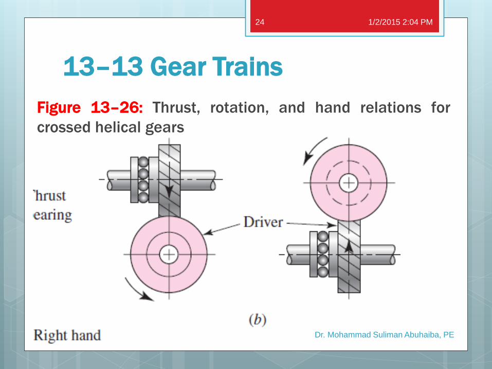
13–13 Gear Trains
Figure 13–26: Thrust, rotation, and hand relations for
crossed helical gears
1/2/2015 2:04 PM
Dr. Mohammad Suliman Abuhaiba, PE
24
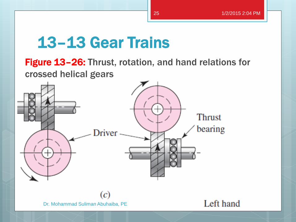
13–13 Gear Trains Figure 13–26: Thrust, rotation, and hand relations for
crossed helical gears
1/2/2015 2:04 PM
Dr. Mohammad Suliman Abuhaiba, PE
25

13–13 Gear Trains Figure 13–26: Thrust, rotation, and hand relations for
crossed helical gears
1/2/2015 2:04 PM
Dr. Mohammad Suliman Abuhaiba, PE
26

Example 13–3
A gearbox is needed to provide a 30:1 (±1%)
increase in speed, while minimizing the overall
gearbox size. Specify appropriate teeth numbers
1/2/2015 2:04 PM
Dr. Mohammad Suliman Abuhaiba, PE
27
Example 13–4
A gearbox is needed to provide an exact 30:1
increase in speed, while minimizing the overall
gearbox size. Specify appropriate teeth numbers
1/2/2015 2:04 PM
Dr. Mohammad Suliman Abuhaiba, PE
28
Example 13–5
A gearbox is needed to provide an exact 30:1
increase in speed, while minimizing the overall
gearbox size. The input and output shafts should
be in-line. Specify appropriate teeth numbers
1/2/2015 2:04 PM
Dr. Mohammad Suliman Abuhaiba, PE
29

13–14 Force Analysis—Spur
Gearing
Figure 13–32
1/2/2015 2:04 PM
Dr. Mohammad Suliman Abuhaiba, PE
30

13–14 Force Analysis—Spur
Gearing
Figure 13–33
1/2/2015 2:04 PM
Dr. Mohammad Suliman Abuhaiba, PE
31
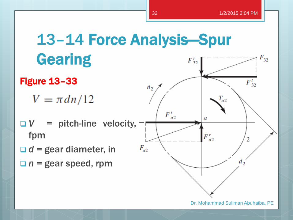
13–14 Force Analysis—Spur
Gearing
Figure 13–33
V = pitch-line velocity,
fpm
d = gear diameter, in
n = gear speed, rpm
1/2/2015 2:04 PM
Dr. Mohammad Suliman Abuhaiba, PE
32

13–14 Force Analysis—Spur Gearing
1/2/2015 2:04 PM
Dr. Mohammad Suliman Abuhaiba, PE
33
English SI
Wt = transmitted load lbf kN
H = power hp kW
V = pitch-line velocity ft/min
d = gear diameter mm
n = speed rpm

Example 13–7
Pinion 2 in Fig. 13–34a runs at 1750 rpm and transmits 2.5
kW to idler gear 3. The teeth are cut on the 20° full-depth
system and have a module of m = 2.5 mm. Draw a FBD of
gear 3 and show all the forces that act upon it.
1/2/2015 2:04 PM
Dr. Mohammad Suliman Abuhaiba, PE
34

13–15 Force Analysis—Bevel Gearing
rav = pitch radius
at midpoint of
tooth for the gear
1/2/2015 2:04 PM
Dr. Mohammad Suliman Abuhaiba, PE
35

Example 13–8
The bevel pinion in Fig. 13–36a rotates at 600 rpm in the
direction shown and transmits 5 hp to the gear. The
mounting distances, the location of all bearings, and the
average pitch radii of the pinion and gear are shown in the
figure. For simplicity, the teeth have been replaced by pitch
cones. Bearings A and C should take the thrust loads. Find
the bearing forces on the gearshaft.
1/2/2015 2:04 PM
Dr. Mohammad Suliman Abuhaiba, PE
36

Example 13–8 1/2/2015 2:04 PM
Dr. Mohammad Suliman Abuhaiba, PE
37

Example 13–8 1/2/2015 2:04 PM
Dr. Mohammad Suliman Abuhaiba, PE
38

13–16 Force
Analysis Helical
Gearing
1/2/2015 2:04 PM
Dr. Mohammad Suliman Abuhaiba, PE
39

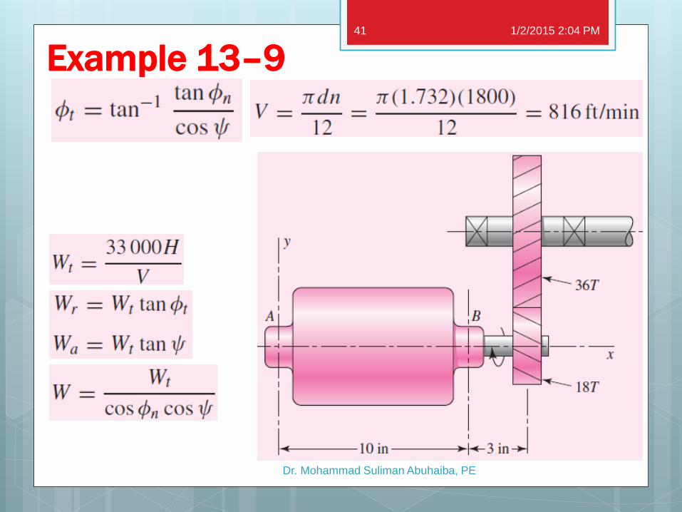
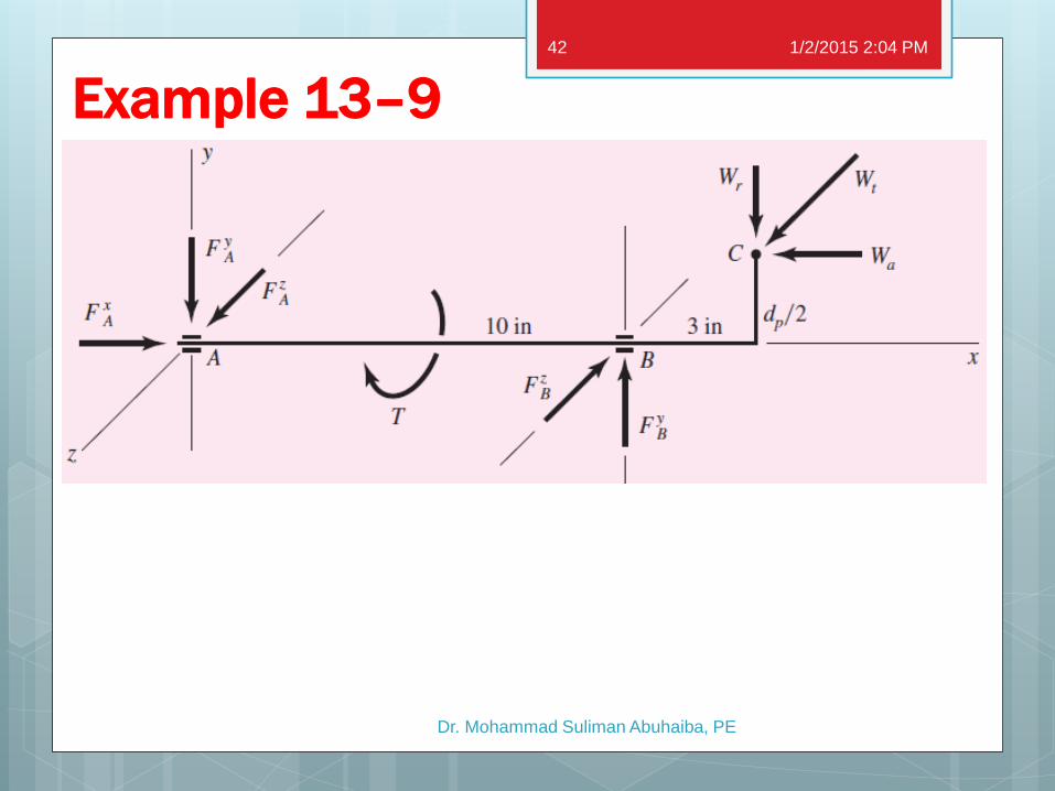
Example 13–9
In Fig. 13–38 a 1-hp electric motor runs at 1800 rpm in the
cw direction, as viewed from the positive x axis. Keyed to the
motor shaft is an 18-tooth helical pinion having a normal
pressure angle of 20°, a helix angle of 30°, and a normal
diametral pitch of 12 teeth/in. The hand of the helix is
shown in the figure. Make a three-dimensional sketch of the
motor shaft and pinion, and show the forces acting on the
pinion and the bearing reactions at A and B. The thrust
should be taken out at A.
1/2/2015 2:04 PM
Dr. Mohammad Suliman Abuhaiba, PE
40
Example 13–9 1/2/2015 2:04 PM
Dr. Mohammad Suliman Abuhaiba, PE
41
Example 13–9 1/2/2015 2:04 PM
Dr. Mohammad Suliman Abuhaiba, PE
42


