Generative Measurement Scenario for
STEP-NC ISO 10303 AP238
Larry MaggianoSenior Systems Analyst
Mitutoyo America Corporation CTLab1 October 2008
Copyright Mitutoyo America Corp. 2008
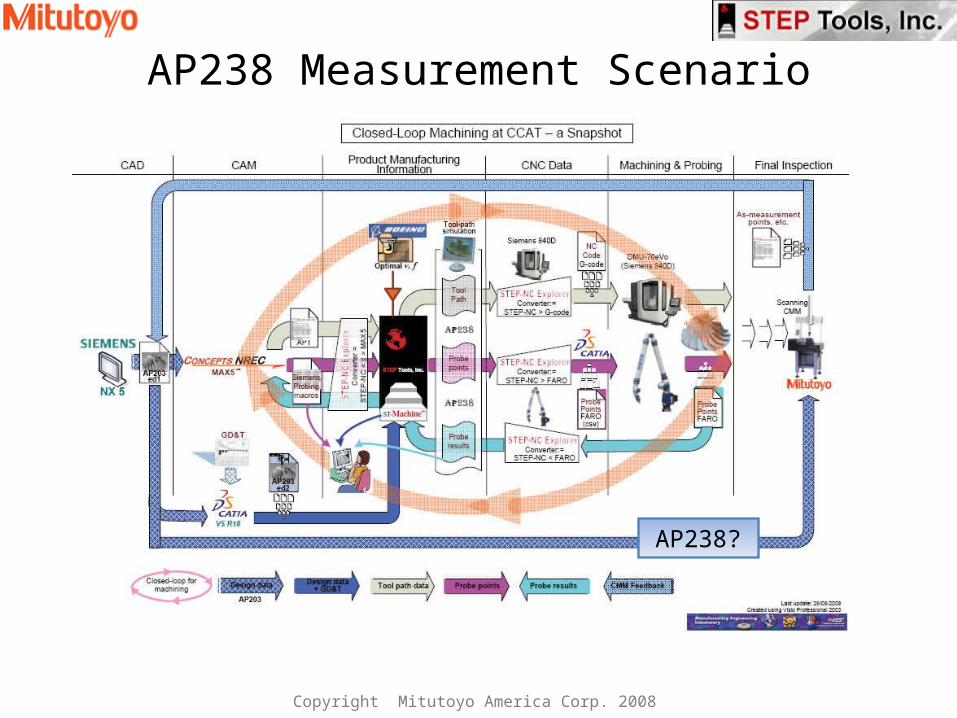
AP238 Measurement Scenario
AP238?
Copyright Mitutoyo America Corp. 2008
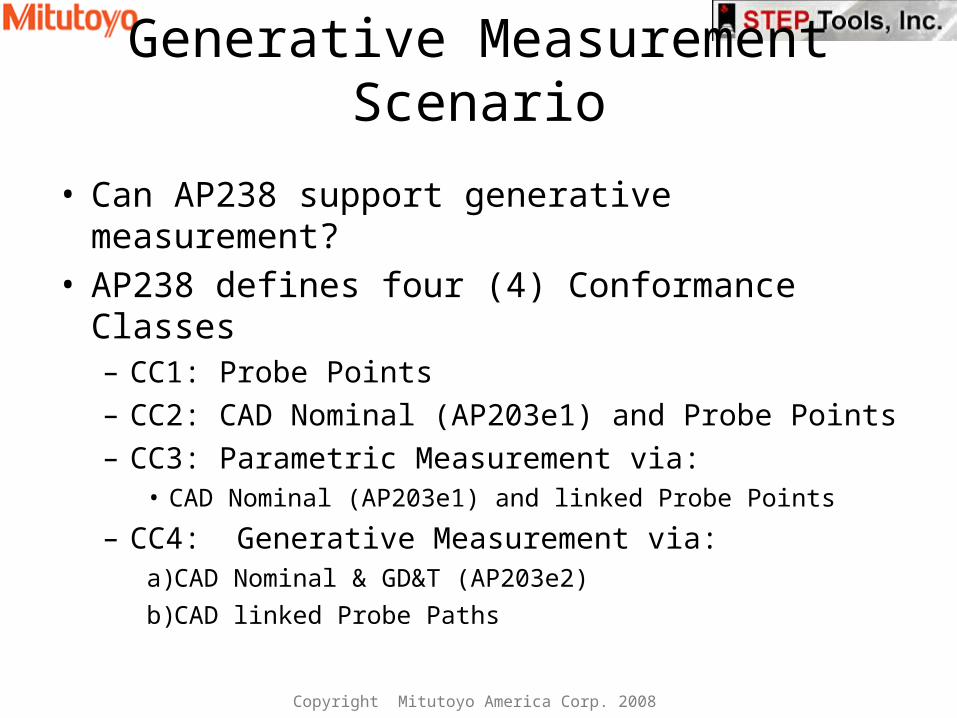
Generative Measurement Scenario
• Can AP238 support generative measurement?• AP238 defines four (4) Conformance Classes
– CC1: Probe Points– CC2: CAD Nominal (AP203e1) and Probe Points – CC3: Parametric Measurement via:
• CAD Nominal (AP203e1) and linked Probe Points
– CC4: Generative Measurement via:a) CAD Nominal & GD&T (AP203e2)b)CAD linked Probe Paths
Copyright Mitutoyo America Corp. 2008
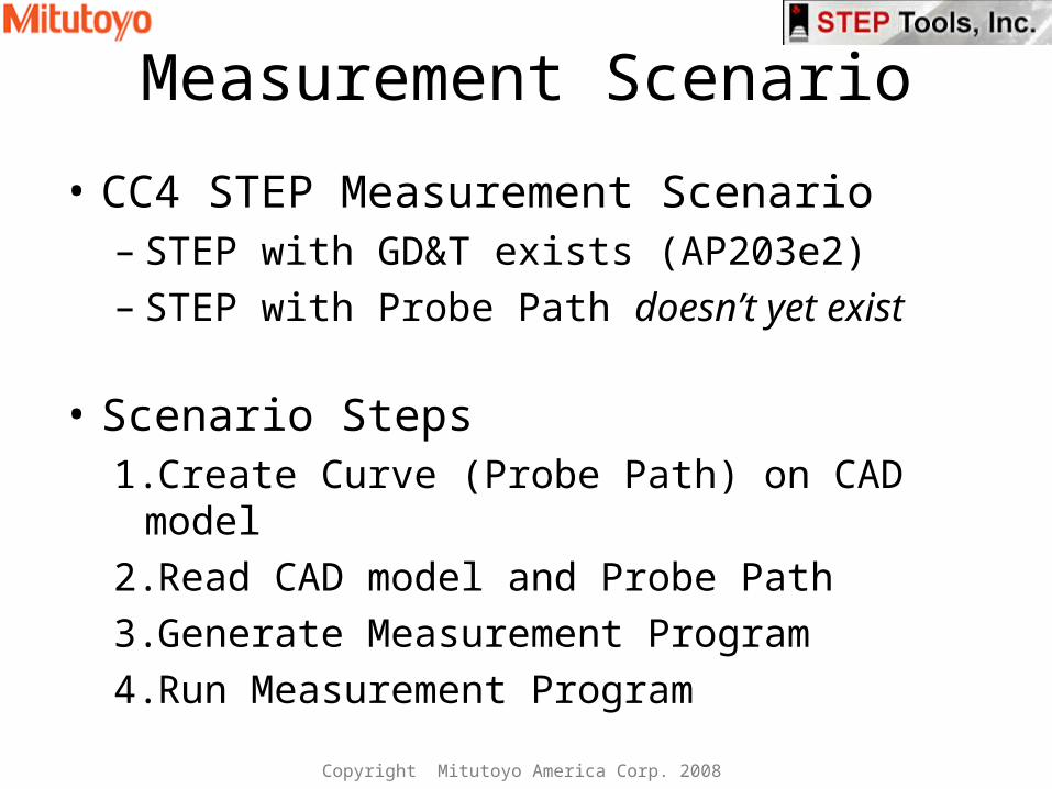
Measurement Scenario
• CC4 STEP Measurement Scenario– STEP with GD&T exists (AP203e2)– STEP with Probe Path doesn’t yet exist
• Scenario Steps1.Create Curve (Probe Path) on CAD model2.Read CAD model and Probe Path3.Generate Measurement Program4.Run Measurement Program
Copyright Mitutoyo America Corp. 2008

Probe Path for In Process Measurement– Probe points along at 1 mm offset from blade edge– Skip leading and trailing edges
Copyright Mitutoyo America Corp. 2008

Probe Path for Post Process Measurement
• Scanning CMM follows Curves, not Points• Use same criteria for In Process Measurement
– Scan Curve at 1 mm offset from blade edge– Skip leading and trailing edges
• Create “Curve on Surface” of Impeller Blade– Curve on Surface is CAD Entity, not data point set– Curve is associated with Surface of Blade– Defines precise Scanning Probe Path
Copyright Mitutoyo America Corp. 2008
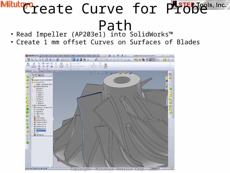
Create Curve for Probe Path• Read Impeller (AP203e1) into SolidWorks™• Create 1 mm offset Curves on Surfaces of Blades
Copyright Mitutoyo America Corp. 2008
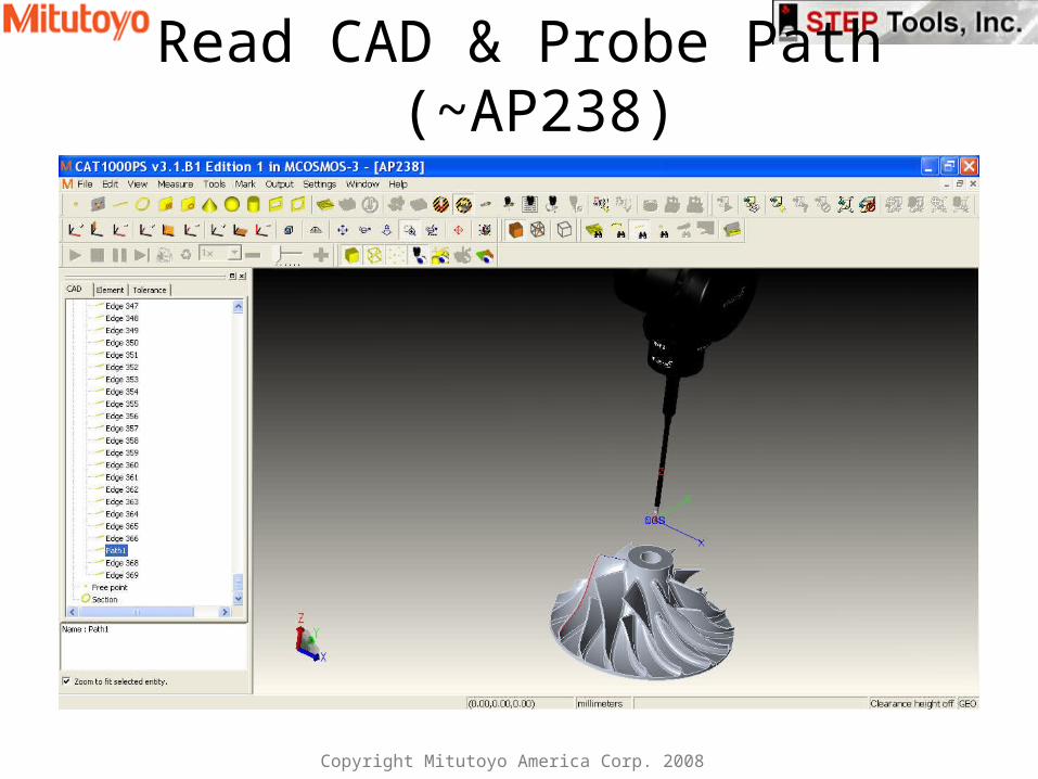
Read CAD & Probe Path (~AP238)
Copyright Mitutoyo America Corp. 2008
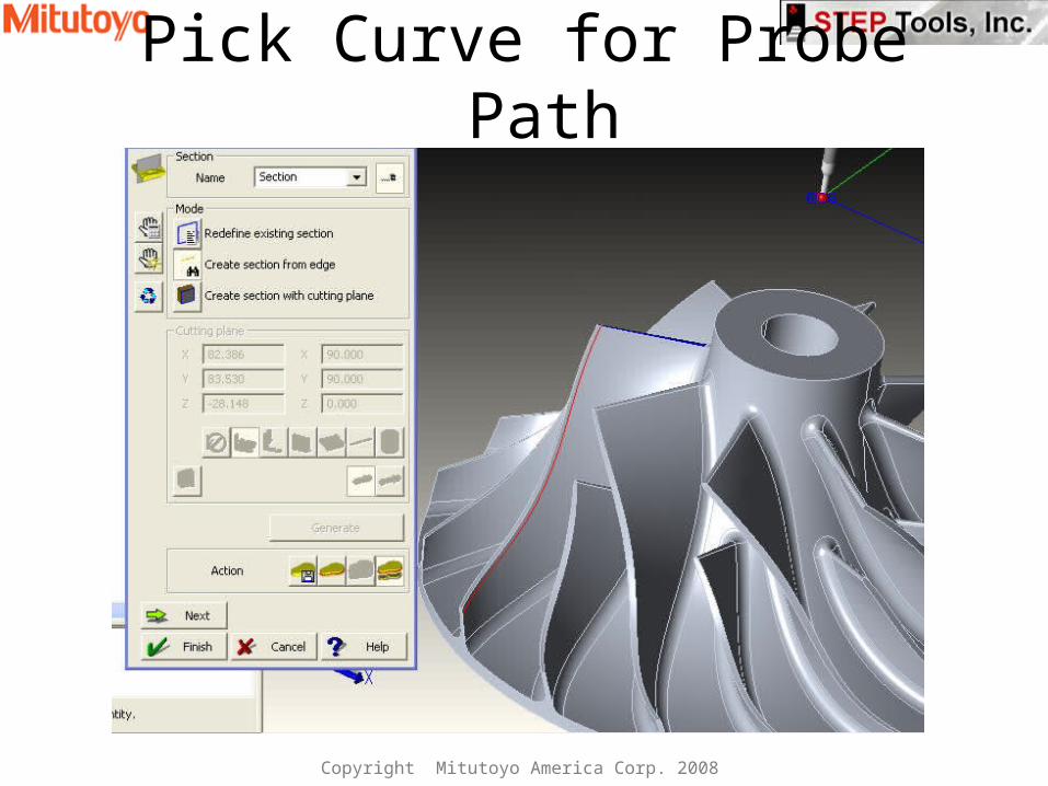
Pick Curve for Probe Path
Copyright Mitutoyo America Corp. 2008
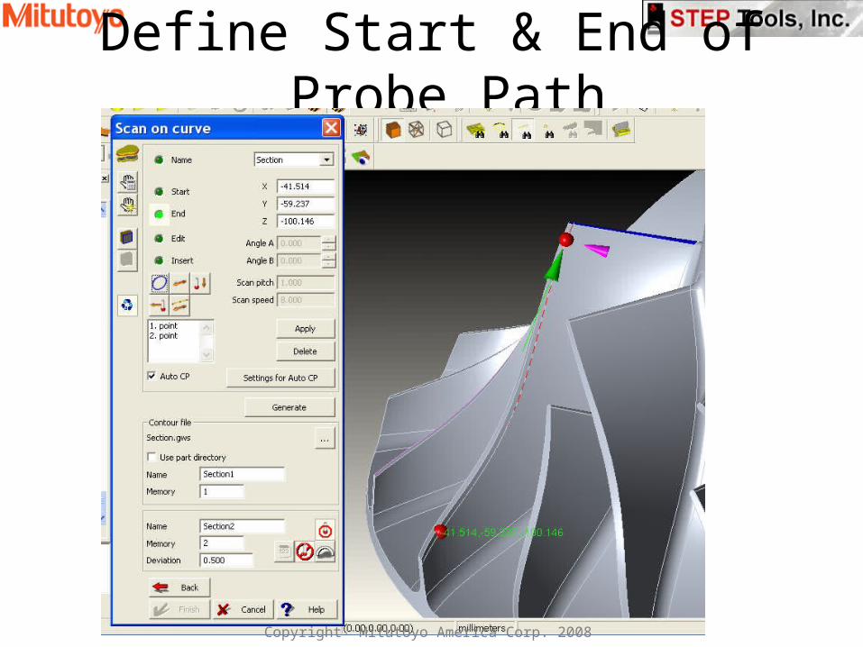
Define Start & End of Probe Path
Copyright Mitutoyo America Corp. 2008
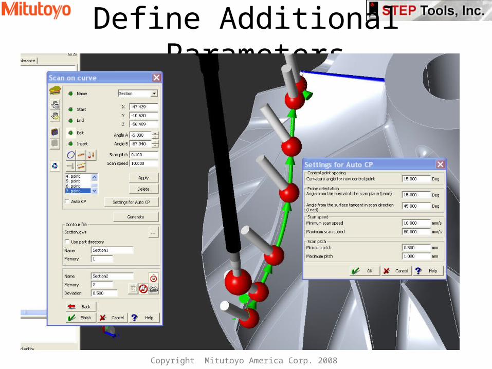
Define Additional Parameters
Copyright Mitutoyo America Corp. 2008
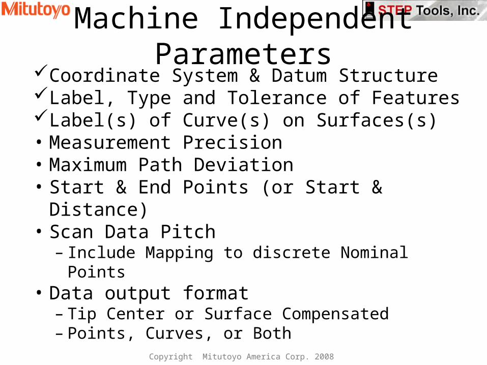
Machine Independent ParametersCoordinate System & Datum StructureLabel, Type and Tolerance of FeaturesLabel(s) of Curve(s) on Surfaces(s)• Measurement Precision• Maximum Path Deviation• Start & End Points (or Start & Distance)• Scan Data Pitch
– Include Mapping to discrete Nominal Points• Data output format
– Tip Center or Surface Compensated– Points, Curves, or Both
Copyright Mitutoyo America Corp. 2008
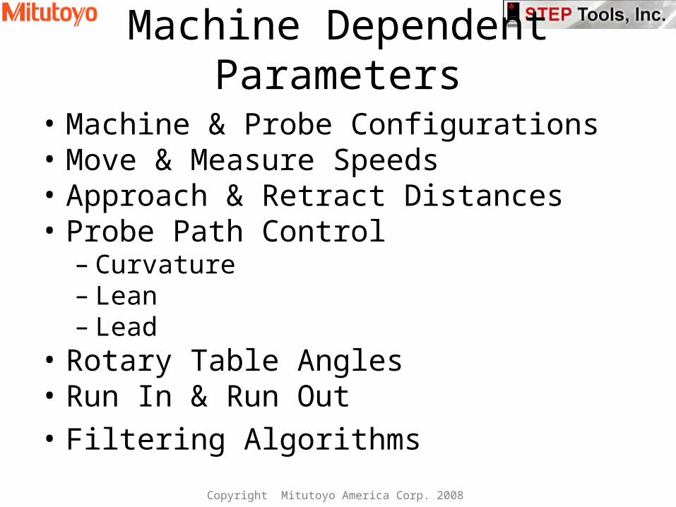
Machine Dependent Parameters
• Machine & Probe Configurations• Move & Measure Speeds• Approach & Retract Distances• Probe Path Control
– Curvature– Lean– Lead
• Rotary Table Angles • Run In & Run Out• Filtering Algorithms
Copyright Mitutoyo America Corp. 2008
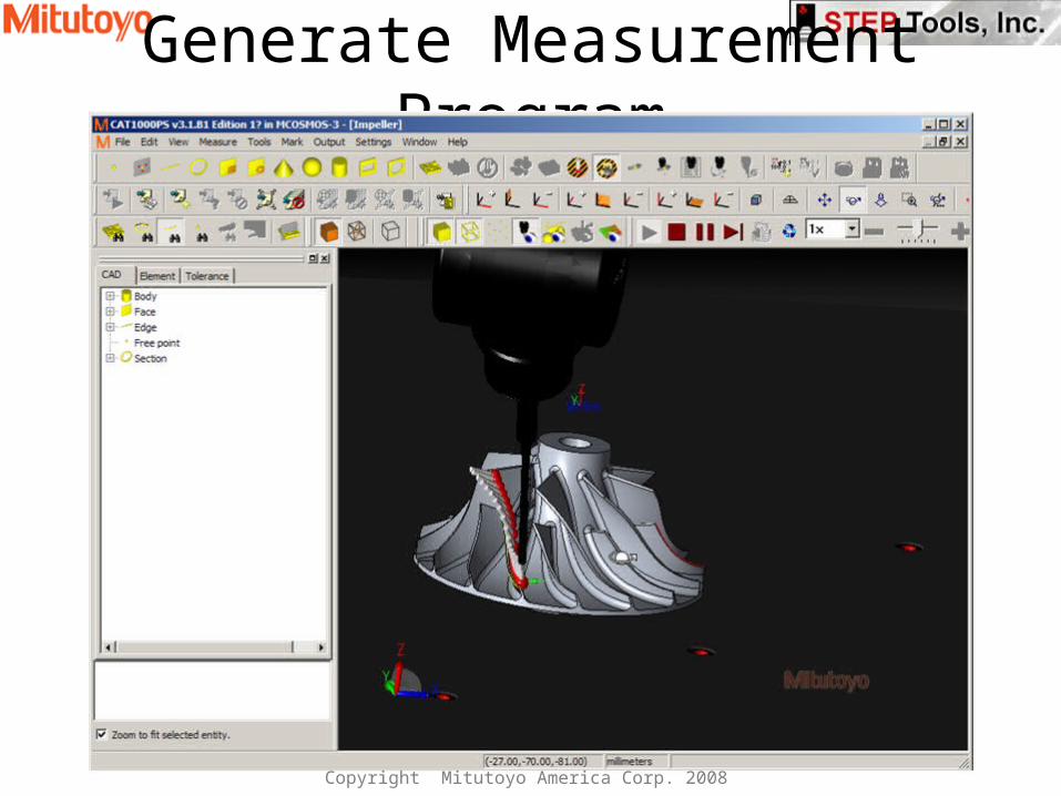
Generate Measurement Program
Copyright Mitutoyo America Corp. 2008
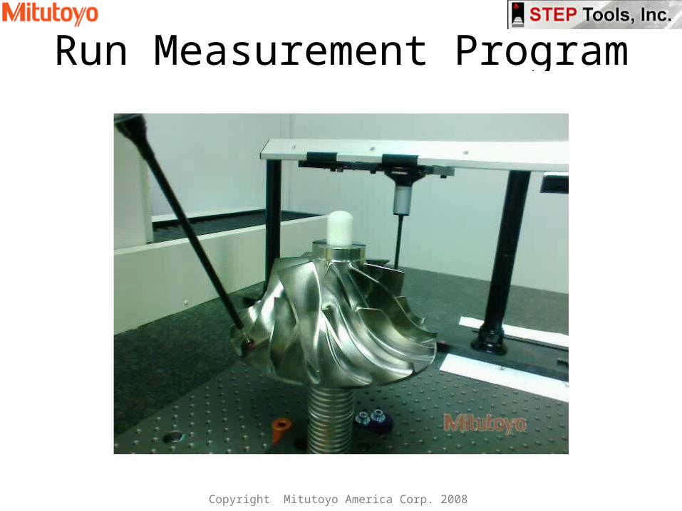
Run Measurement Program
Copyright Mitutoyo America Corp. 2008

Scan Probe Path as an AP238 Entity
• Created by STEP Tools for AP238 TC
ENTITY curve_probing SUBTYPE OF (touch_probing)curve_to_be_measured : bounded_curve;start_position : OPTIONAL axis2_placement_3d;start_direction : OPTIONAL direction;distance : OPTIONAL length_measure;curve_axis : OPTIONAL bounded_curveas_measured_curve : OPTIONAL bounded_curve;as_measured_curve_normal : OPTIONAL bounded_curve;its_technology : OPTIONAL technologypath_maximum_deviation : OPTIONAL bounded_curve;
END_ENTITY;
Copyright Mitutoyo America Corp. 2008
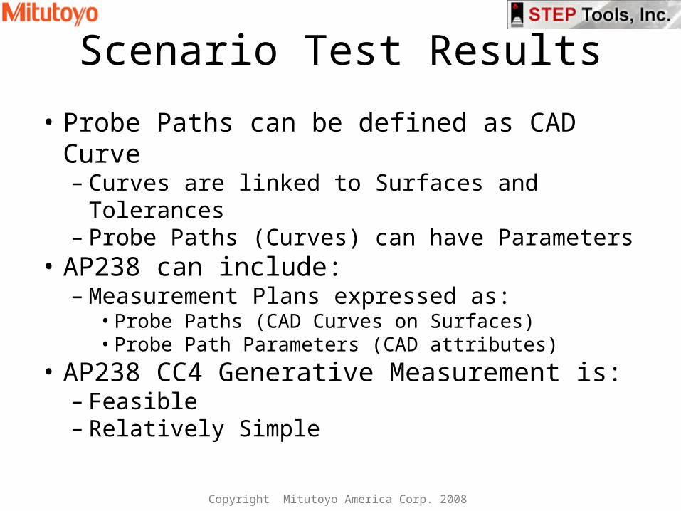
Scenario Test Results
• Probe Paths can be defined as CAD Curve– Curves are linked to Surfaces and Tolerances– Probe Paths (Curves) can have Parameters
• AP238 can include:– Measurement Plans expressed as:
• Probe Paths (CAD Curves on Surfaces)• Probe Path Parameters (CAD attributes)
• AP238 CC4 Generative Measurement is:– Feasible– Relatively Simple
Copyright Mitutoyo America Corp. 2008
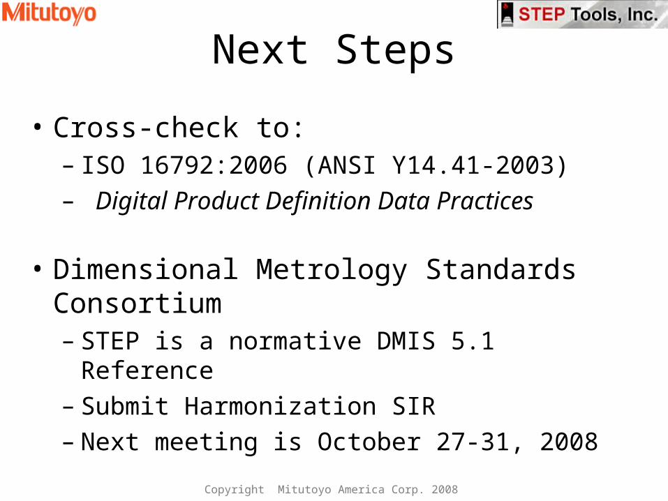
Next Steps
• Cross-check to: – ISO 16792:2006 (ANSI Y14.41-2003)– Digital Product Definition Data Practices
• Dimensional Metrology Standards Consortium– STEP is a normative DMIS 5.1 Reference– Submit Harmonization SIR – Next meeting is October 27-31, 2008
Copyright Mitutoyo America Corp. 2008
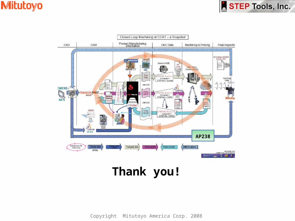
Thank you!
AP238
Copyright Mitutoyo America Corp. 2008


